New Holland CX720, CX740, CX760, CX780, CX820, CX840, CX860, CX880. Operator's Manual - page 4
SECTION 2 - CONTROLS, INSTRUMENTS AND OPERATION
MENUS AND SUB-MENUS
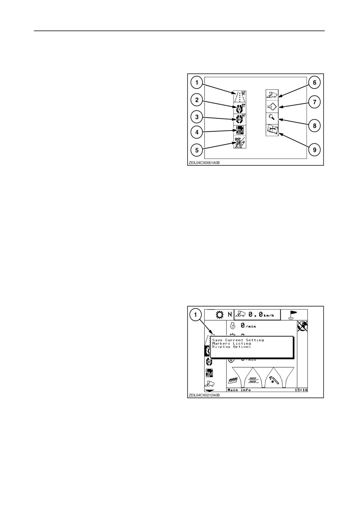
The different menus on the menu bar are listed and
will always appear in that sequence.
1. Road info screen
2. Main info screen
3. Custom info screen
4. Harvest info screen
5. Automatic crop settings screen
6. Combine info screen
7. Configuration and calibration info screen
8. Diagnostics info screen
65
9. Service info screen
NOTE: Pressing the ‘‘escape’’ key when a menu
down the ladder is selected, will cause the cursor to
jump:
• to the road info screen when road mode is
selected.
• to the main info screen when field mode is
selected.
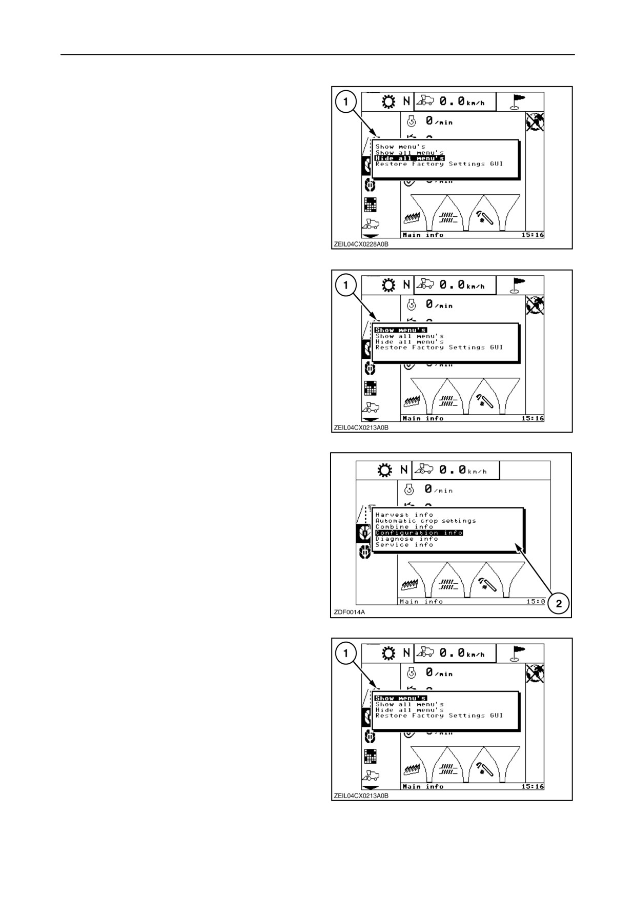
To view only the “standard” screens on the display,
proceed as follows:
1. Select the “Road info”, “Main info” or “Custom
info” screen and press “enter”.
2. A pop-up 1 screen appears.
3. Select in this list
“Display options”, using the
“down” navigation keys and press “enter”.
66
2-50
SECTION 2 - CONTROLS, INSTRUMENTS AND OPERATION
4. A pop-up 1 screen appears.
5. Select in this list “Hide all menus”, using the “up”
and “down” navigation keys and press “enter”.
6. Pop-up 1 screen will disappear and only the
“Road info”, “Main info”, “Custom info”, “Harvest
info” and “Automatic crop settings” screen are
visible on the display.
67
To display an extra menu of your choice on the
InfoViewt display, proceed as follows:
1. Select the “Road info”, “Main info” or
“Custom info” screen and press “enter”.
2. Select in this pop-up screen “Display options”,
using the
“down” navigation keys and press
“enter”.
3. A pop-up 1 screen appears.
4. Select in this list “Show menus”, using the “up”
and “down” navigation keys and press “enter”.
68
5. Select in this pop-up 2 screen the menu to view
on the screen, using the
“up” and
“down”
navigation keys and press “enter”.
6. The pop-up screen will disappear and the
selected menu together with the
“standard”
menus are visible on the InfoViewt.
NOTE: To view (or to remove) more screens on the
display repeat this procedure.
69
NOTE: To show all menus, select “Show all menus”
in pop-up screen 1 and press “enter”.
70
2-51
SECTION 2 - CONTROLS, INSTRUMENTS AND OPERATION
MDM Protected mode
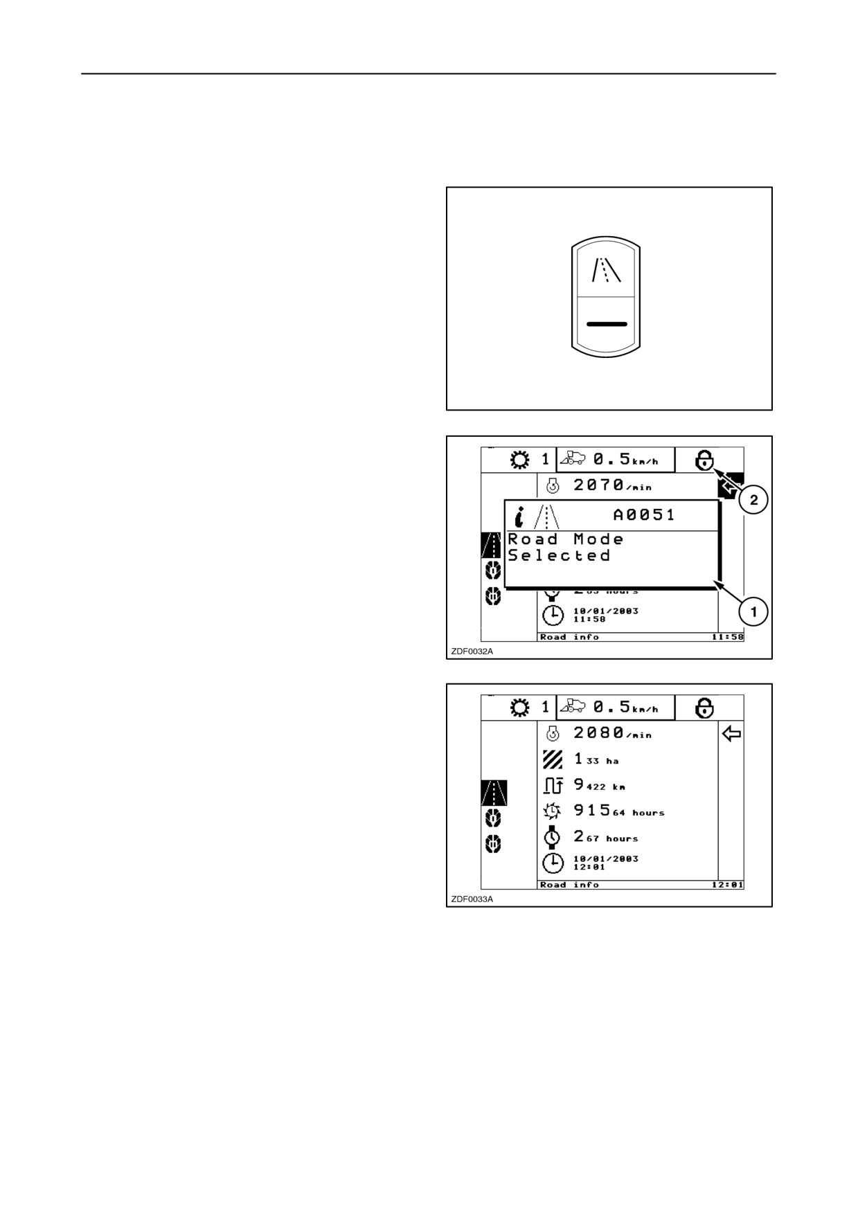
To select this mode, proceed as follows:
1. Select “road mode” with the road mode selector
switch located at the right-hand module.
NOTE: You will only be able to select the road mode
when threshing is not engaged, grain tank covers and
unload tube are closed.
71
2. A pop-up screen 1 appears:
“Road mode selected”.
3. Icon 2 (locked padlock) appears in the indicator
bar.
72
All the menus except the standard menus are hidden
from the screen.
It is not possible anymore to do any calibrations or
configurations, input/output diagnostics, read service
information, etc..
73
The only way to make appear the hidden menus
again is to deselect road mode by select “field mode”
with the road mode selector switch.
The protected mode will be cancelled automatically
and will restore the full menu’s on the InfoViewt.
2-52
SECTION 2 - CONTROLS, INSTRUMENTS AND OPERATION
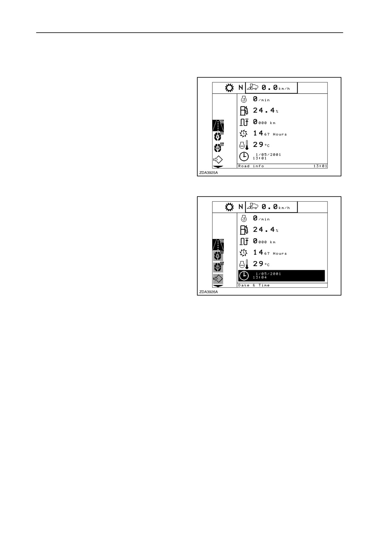
I ROAD INFO SCREEN
When contact is switched on and the road mode is
selected with the road/field mode selector switch, the
monitor will enter the road info screen.
NOTE: It is not possible to engage the threshing
mechanism if the road info screen is selected with the
road mode selector switch.
74
Enter the information box by pressing the ”right”
navigation key. The cursor will jump to the item that
was the last time selected when escaping the
information box.
The selected symbol will blink and in the text bar a
description of the selected item is shown.
To select another item, use the ”up” and/or ”down”
navigation keys. When these navigation keys are not
used for a while, the selected symbol will stop blinking
and will be inverted until the navigation keys are used
again.
75
The information displayed in the information box, six
fields, and the sequence of these fields can be
changed (refer to paragraph
”Configuration and
calibrations” sub headed ”Road info screen setup” in
this section).
The actual values are displayed next to the symbol.
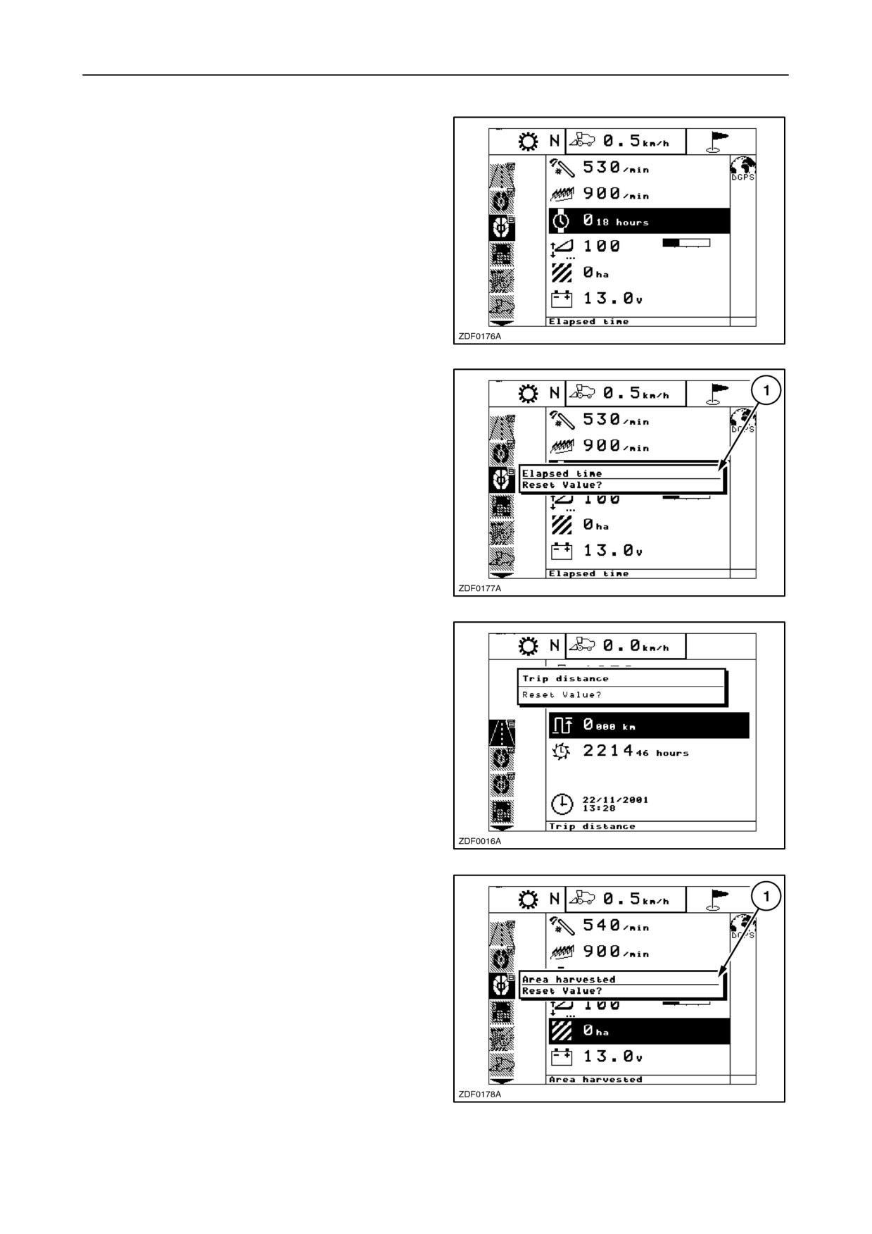
NOTE: It is possible to reset the value to zero from
items
“Elapsed time”,
“Trip distance” or
“Area
harvested”
(If selected: Road, Main or Custom info
screen).
2-53
SECTION 2 - CONTROLS, INSTRUMENTS AND OPERATION
Elapsed time
It is possible to check the elapsed time, if this item is
selected.
To set this value to zero, proceed as follows:
1. Select “Elapsed time” in the information box,
using the navigation keys and press “enter”.
76
2. A pop-up screen 1 appears.
Message: “Reset value?”
3. Press the “enter” key to reset the value to zero.
77
Trip distance
It is possible to check the trip distance, if this item is
selected.
To set this value to zero, proceed as follows:
1. Select
“Trip distance” in the information box,
using the navigation keys and press “enter”.
2. A pop-up screen appears:
Message: ” Reset value?”.
3. Press the “enter” key to reset the value to zero.
78
Area harvested
It is possible to check the area harvested, if this item
is selected.
1. Select “Area harvested” in the information box,
using the navigation keys and press “enter”.
2. A pop-screen (1) appears.
Message: ”Reset value?”
3. Press the “enter” key to reset the value to zero.
79
2-54
SECTION 2 - CONTROLS, INSTRUMENTS AND OPERATION
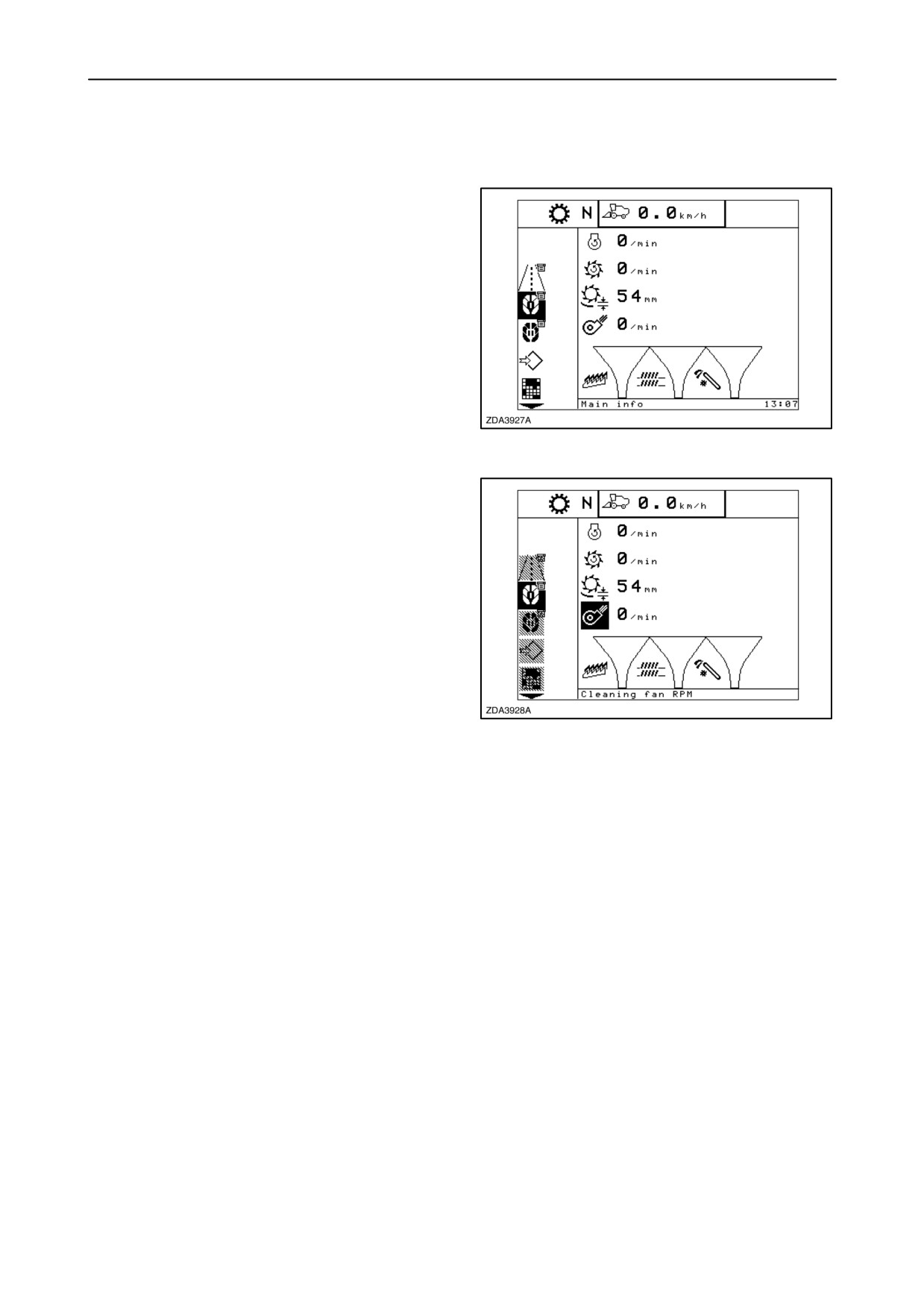
II MAIN INFO SCREEN
General
When key is switched on and the field mode is
selected with the road/field mode selector switch, the
monitor will enter the main info screen.
80
Enter the information box by pressing the ”right”
navigation key. The cursor will jump to the item that
was the last time selected when escaping the
information box.
The selected symbol will blink and in the text bar a
description of the selected item is shown.
To select another item, use the
”up” or
”down”
navigation keys. When the navigation keys are not
used for a while, the selected symbol will stop blinking
and will be inverted until the navigation keys are used
again.
81
The information displayed in the information box, the
first four fields and the sequence of these fields can
be changed (refer to paragraph ”Configuration and
calibrations” sub headed ”Main info screen setup” in
this section). The actual values of these four items
are displayed next to the symbol.
The three bargraphs at the bottom of the information
box are factory-set and can not be changed.
The first two bargraphs are provided to display the
straw walker losses and the sieves losses. The
bargraph segments lights up proportionally to the
losses and to the sensitivity setting (see further in this
paragraph).
The third bargraph is provided to display the volume
of return material that passes through the returns
auger. The bargraph segments lights up
proportionally to volume of return and to the
sensitivity setting (see further is this paragraph).
2-55
SECTION 2 - CONTROLS, INSTRUMENTS AND OPERATION
Sensitivity setting of straw walker and sieve
loss sensor
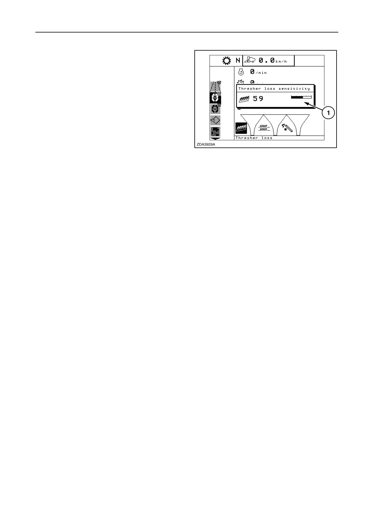
When selecting the straw walker (thresher) loss
bargraph or the sieves loss bargraph, a pop-up
screen 1 appears on the screen. The sensitivity
setting is displayed from 0 to 100, the higher the
number, the higher the sensitivity.
To set both sensitivities, proceed as follows:
1.
Drive the combine in the field. Stop the combine
after a hundred metres and take a grain sample.
Check for grain losses in the swath. If the result
82
is unsatisfactory, carry out the necessary
adjustments
(refer to Section
3, paragraph
headed: ”Combine performance checks”).
2.
Repeat step 1 until a good result is obtained.
3.
Drive the correct adjusted combine in the field
and select the highest ground speed consistent
with obtaining good results.
4.
Select the straw walker loss bargraph and
change the sensitivity with the ”+” and/or ”-” key
until the lower half of the bargraph is illuminated.
Press the ”enter” key to store the new sensitivity
value.
5.
Select the sieves loss bargraph and change the
sensitivity with the ”+” and/or ”-” key until the
lower half of the bargraph is illuminated. Press
the ”enter” key to store the new sensitivity value.
6.
Increase the ground speed until one of the bars
is completely illuminated.
7.
Stop the combine and check if the grain loss has
clearly increased. If not, this means that the
sensitivity of the bar that was completely
illuminated, was set too high. Set the sensitivity
on this bar on a lower level at the speed selected
under point 6.
If the rate of loss increases, more segments will
appear on the bargraph. If the rate of loss
decreases, segments will extinguish.
8.
The setting of the sensitivities of both bargraphs
has to be performed or at least checked
whenever changing from field or crop.
2-56
SECTION 2 - CONTROLS, INSTRUMENTS AND OPERATION
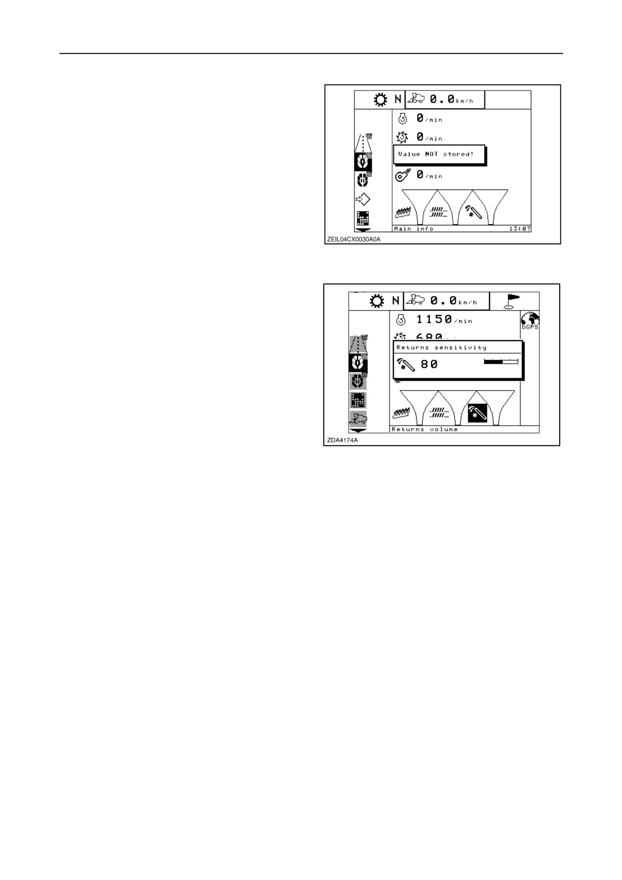
NOTE: A message ”Value not stored” will appear on
the screen, linked with an audible beep, if the new
sensitivity has not been stored by pressing the ”enter”
key.
NOTE: It is also possible to change the sensitivity of
the left and right straw walkers and sieves in the
combine information menu. Refer to paragraph
”COMBINE INFORMATION”, loss information.
or
in the configuration info. Refer to paragraph
“CONFIGURATION AND CALIBRATIONS”, item
“Cleaning” to change the “sieve loss sensitivity” and
item
“Residue” to change the
“thresher loss
83
sensitivity”.
Setting of the returns capacity
When selecting the returns capacity bargraph, a
pop-up screen appears on the screen. The sensitivity
setting is displayed from 0 to 100 in steps of 1.
NOTE: Higher number = higher sensitivity etc
Select the returns capacity bargraph and change the
sensitivity with the ”+” and/or ”-”. Press the ”enter”
key to store the new sensitivity value.
84
2-57
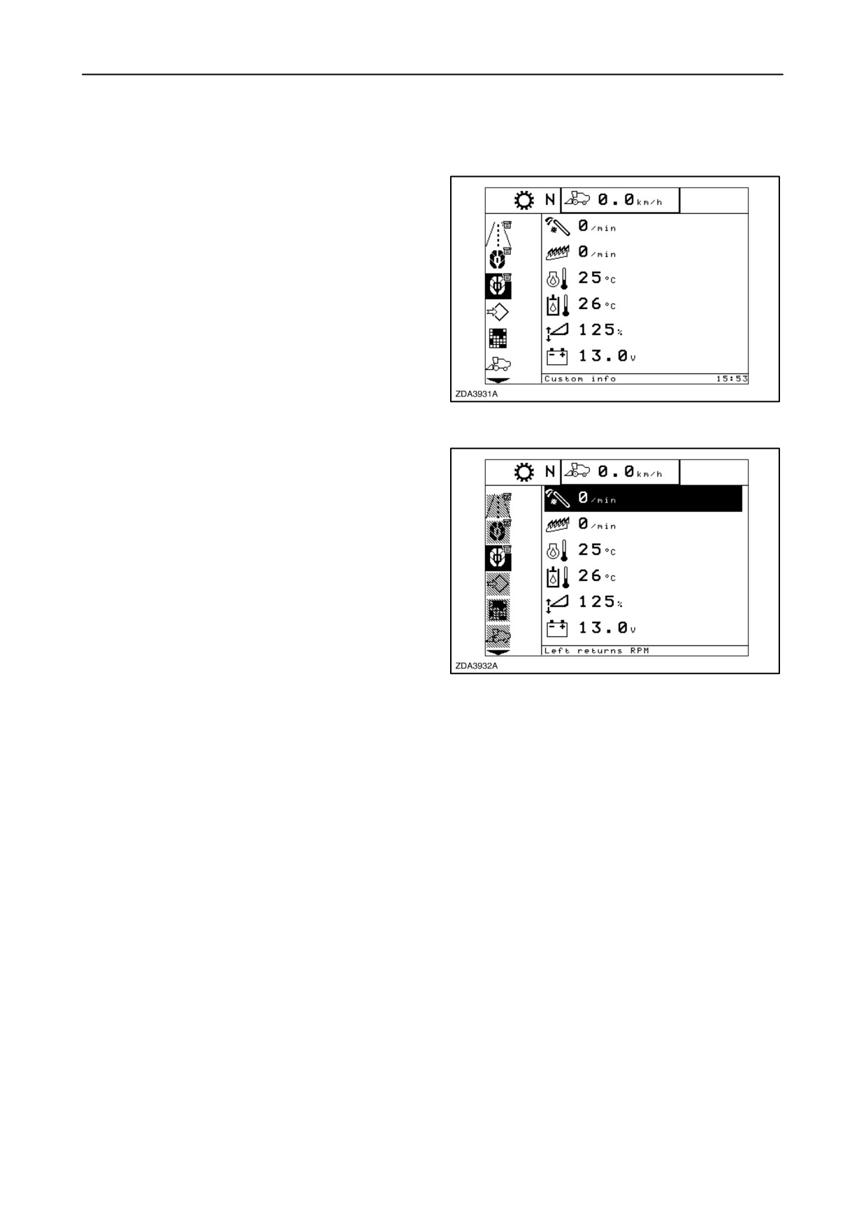
SECTION 2 - CONTROLS, INSTRUMENTS AND OPERATION
III CUSTOM INFO SCREEN
Select the custom info screen in the menu bar by
using the ”up” and ”down” navigation keys.
85
Enter the information box by pressing the ”right”
navigation key. The cursor will jump to the item that
was last selected when escaping the information box.
The selected symbol will blink and in the text bar a
description of the selected item is shown.
To select another item, use the
”up” or
”down”
navigation keys. When the navigation keys are not
used for a while, the selected symbol will stop blinking
and will be inverted until the navigation keys are used
again.
The information displayed in the information box, six
86
fields, and the sequence of these fields can be
changed (refer to paragraph
”Configuration and
calibrations” sub headed: ”Custom info screen setup”
in this section).
The actual values are displayed next to the symbol.
2-58
SECTION 2 - CONTROLS, INSTRUMENTS AND OPERATION
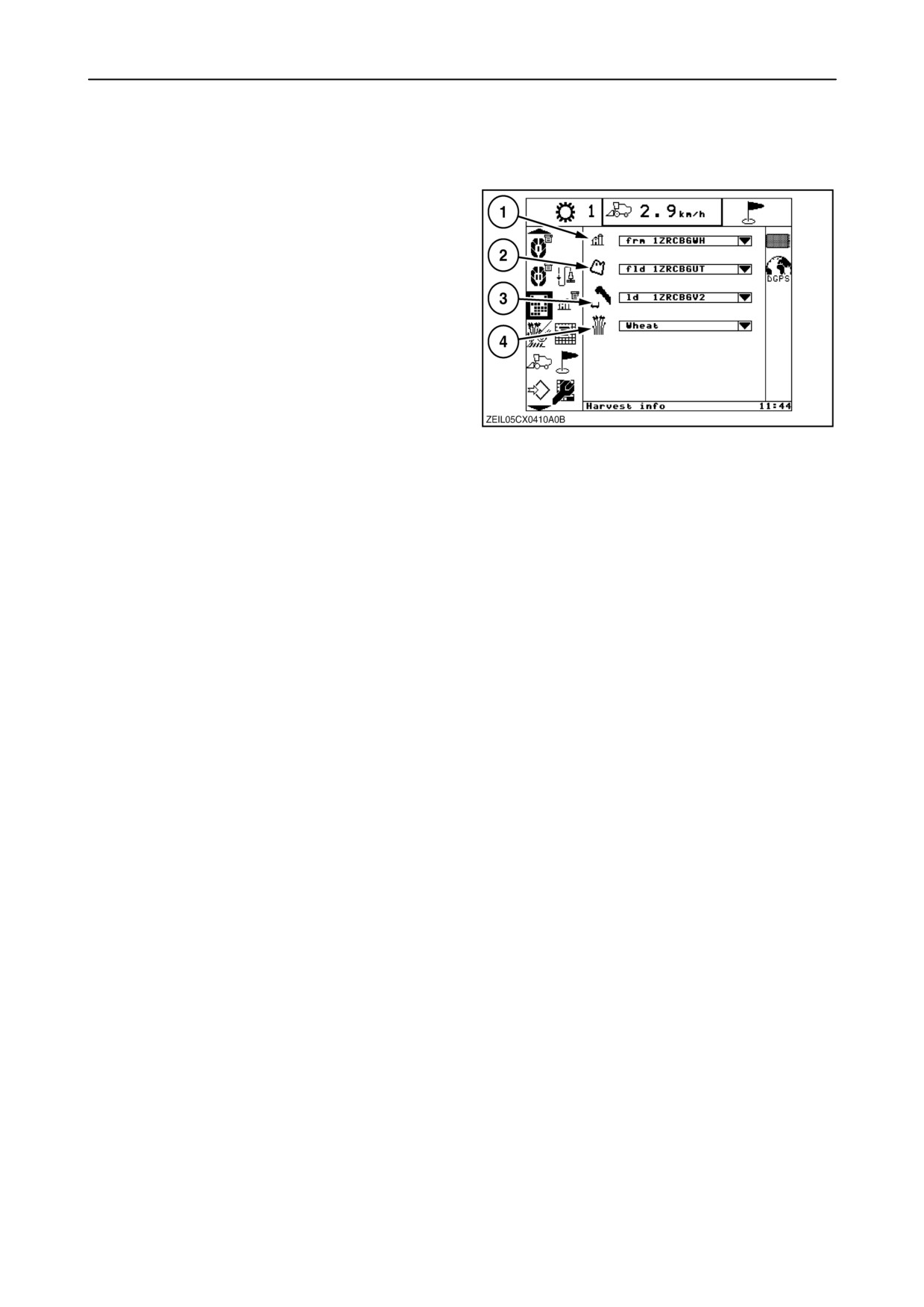
IV HARVEST INFO SCREEN
Select the harvest information screen in the menu bar
by using the ”up” and ”down” navigations keys.
A sub-menu will appear next to the menu bar.
The screen is made up of these parameters:
FARM (1) - user assigned identification for the farm
being harvested. 12 character limit.
FIELD (2) - user assigned identification for the field
being harvested. 12 character limit.
87
LOAD (3) - user assigned identification for a sub
identifier for a field. 12 character limit.
CROP (4) - operator can change the crop type
associated with the active load.
NOTE: Crop type can only be changed before
harvesting into the active load.
In order to best organize your data, it is
recommended that you name your farms and fields
prior to harvest and use a consistent naming
convention.
Loads are a means of creating specific data sets
within an associated farm and field.
Naming these loads may be helpful if you are
harvesting a series of test plots and choose to name
each load as a separate hybrid.
2-59
SECTION 2 - CONTROLS, INSTRUMENTS AND OPERATION
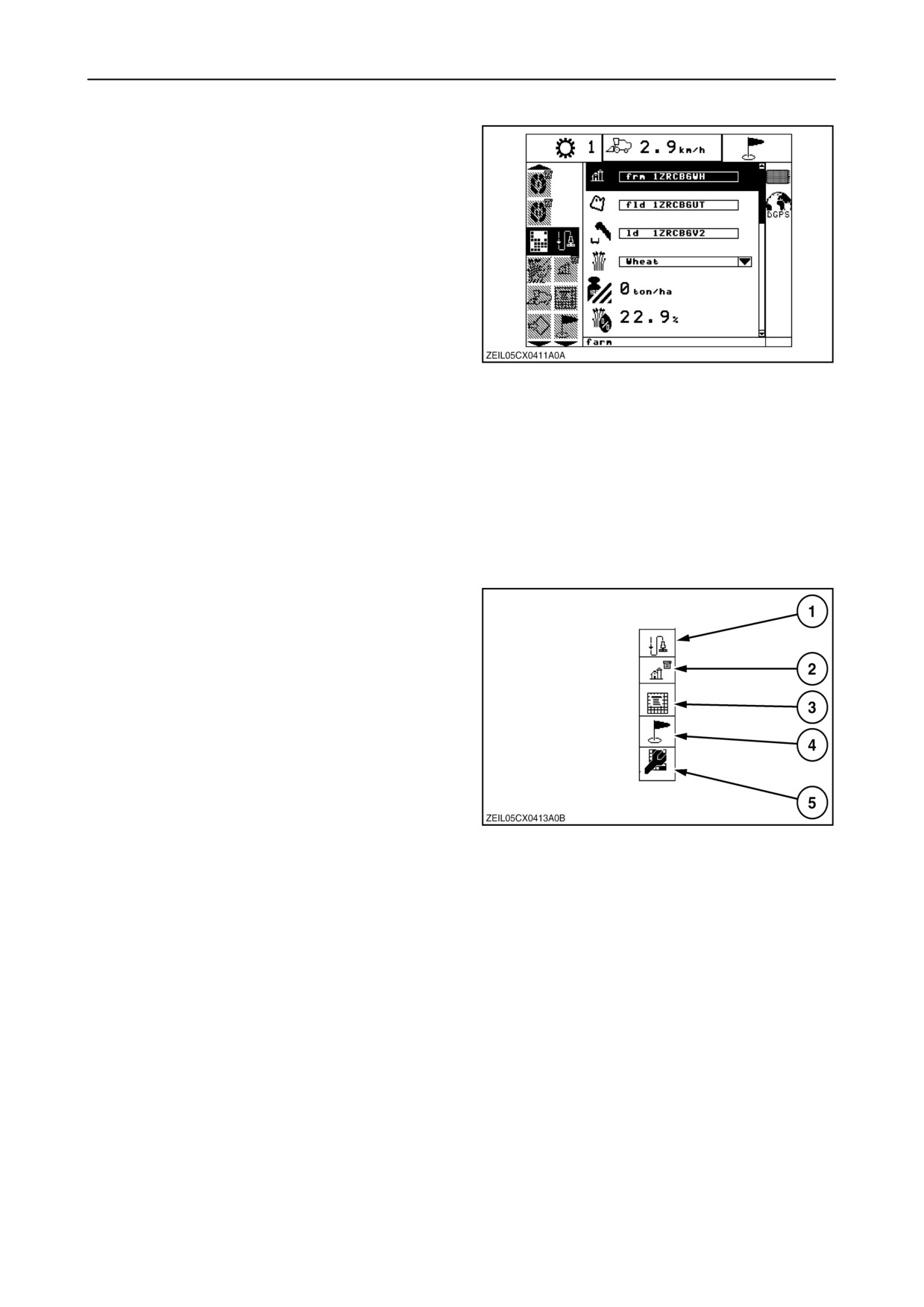
Enter the sub-menu bar by pressing the
”right”
navigation key. The cursor will jump to the sub menu
that was last selected when escaping the sub menu
bar.
The selected sub menu will blink and in the text bar
a description of the selected sub menu is shown.
To select another sub menu, use the ”up” and ”down”
navigation keys. When the navigation keys are not
used for approximately
8 seconds, the selected
symbol will stop blinking and will be inverted until the
navigation keys are used again.
NOTE: Upon system startup, harvest records may be
88
present on two separate components, the InfoViewt
flash or the PC data card. The PC card is the primary
data medium. If a PC data card is not detected, the
InfoViewt flash will allow creation and usage of a
maximum of 10 Farm/Fields and a maximum of 16
Loads.
NOTE: While multiple Farms, Fields, and Loads can
be created and used without a PC card inserted, only
the active Farm/Field/Load will be retained on a
power cycle unless a PC card is inserted and allowed
to merge before power down.
The different sub-menus in the harvest information
menu are listed and will always appear in that
sequence.
1. Instantaneous values
2. Select active load (Farm/ Field/ Load)
3. Harvest summary
4. Markers setup
(Only with data logger and (D)GPS installed)
5. Calibration
The Instantaneous values screen displays
89
information which is specific to the current load
(current data set). It is used for real time feedback
during harvest. The Harvest summary screen
displays information spanning across data sets
(possible multiple loads).
See parameter list below:
2-60
SECTION 2 - CONTROLS, INSTRUMENTS AND OPERATION
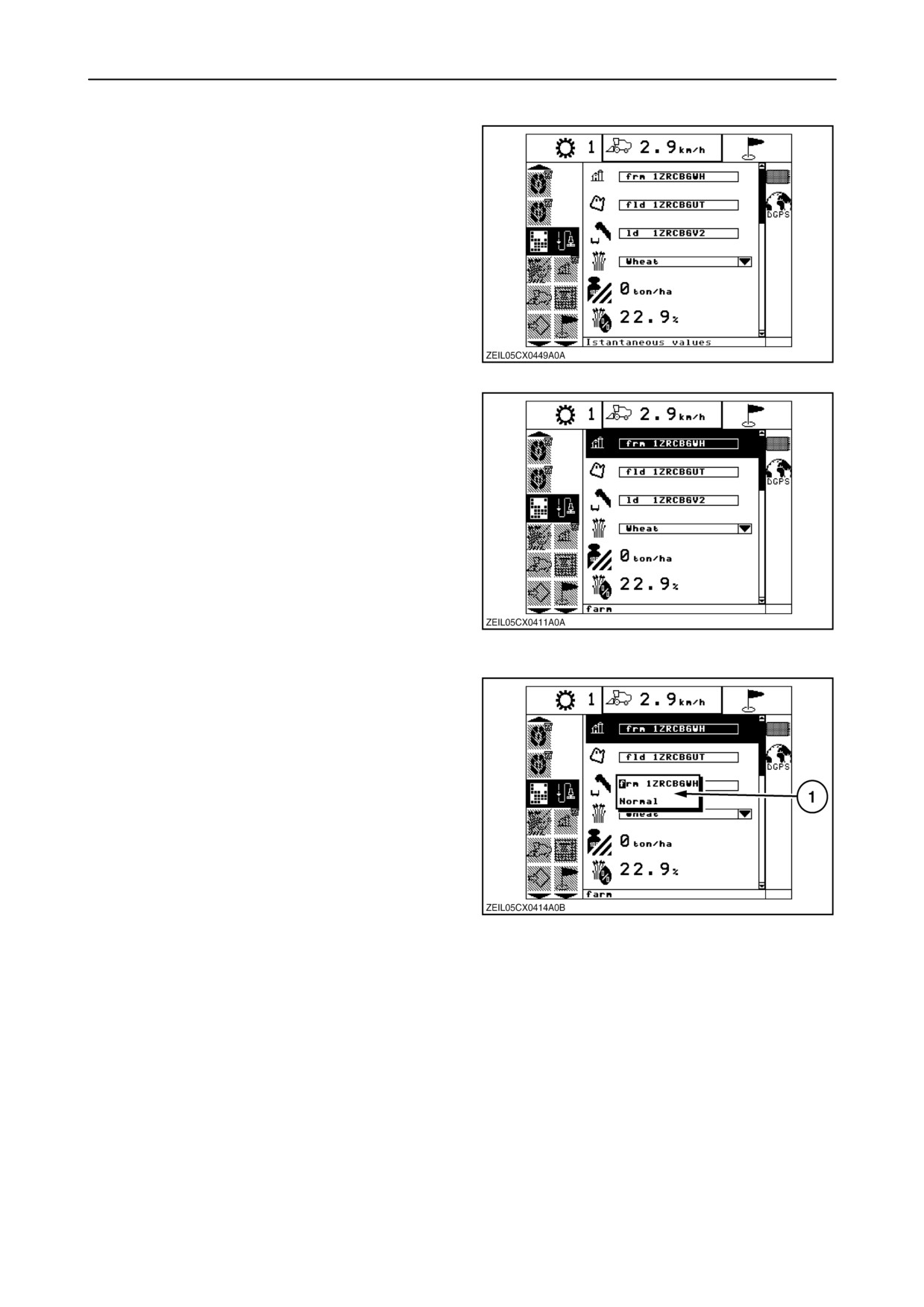
1. Instantaneous values
Select the ”Instantaneous values” sub menu in the
sub menu bar by using the navigation keys.
The instantaneous values screen can be used to view
a fixed list of parameters associated with the current
active load. It is also used to edit the active
Farm/Field/Load names.
Enter the information box by pressing the ”right”
navigation key. The selected item will blink and in the
text bar a description of the selected item is shown.
90
The Instantaneous values screen allows for editing of
the active Farm, Field, or Load.
The active name can be edited at any time. The farm,
field, and load name edit function works in the same
manner for all objects.
From the Instantaneous values screen, use the up
and down arrow keys on the keypad to navigate to the
item to be edited.
NOTE: To obtain correct values, the moisture sensor,
and the flow sensor needs to be correctly calibrated
(refer to paragraph headed ”Calibrations for yield
91
monitoring or mapping”.
Pressing the “enter” key brings up the edit function
window (1).
Using the keypad, the name is edited, left justified and
12 characters maximum.
Pressing the ”enter” key, returns the edited name to
the corresponding selector.
Pressing the ESC key aborts the edit process.
Any change of name will carry all harvest info saved
data from the old name to the new name.
92
2-61
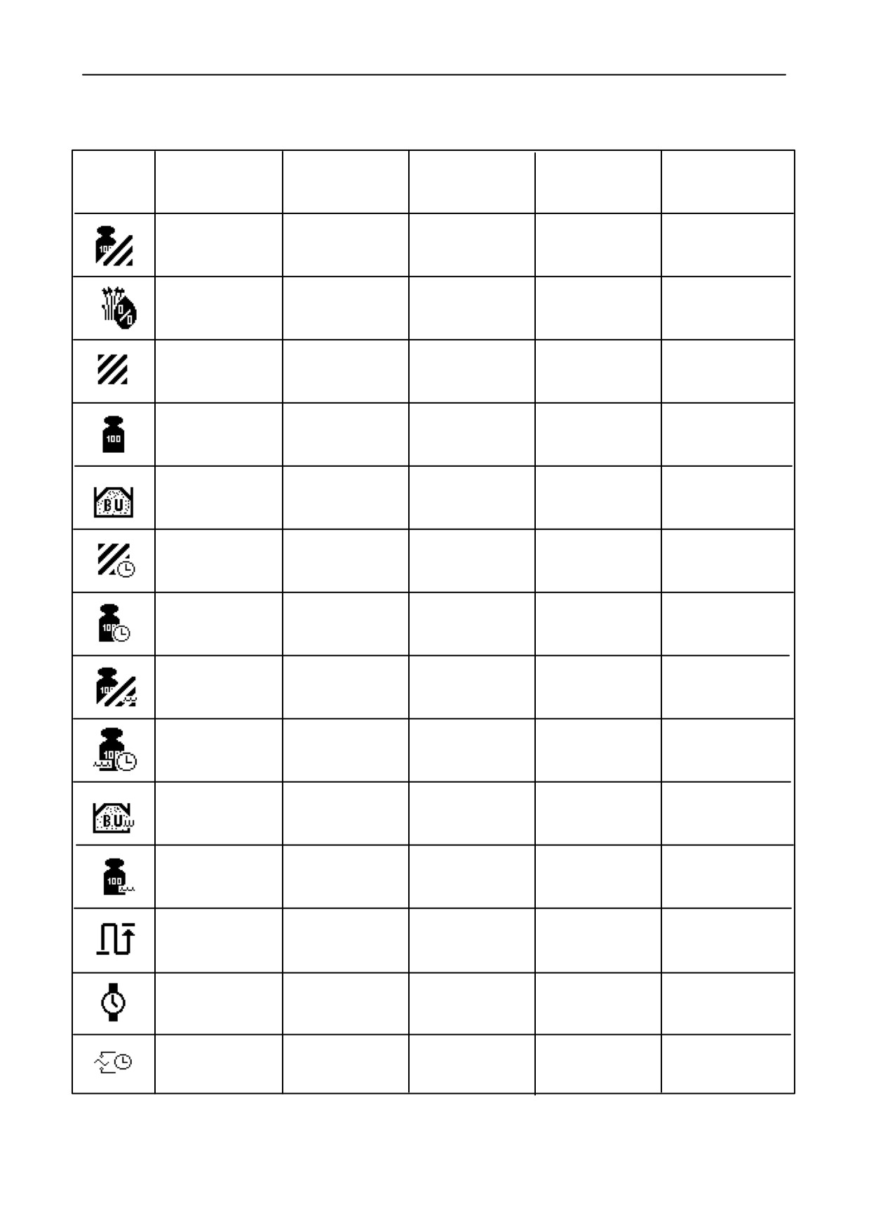
SECTION 2 - CONTROLS, INSTRUMENTS AND OPERATION
Instantaneous parameter list
Icon
Label
US format
US units
Metric format
Metric units
Yield - Dry
XXX.XX
bu/ac
XXX.XXX
ton/ha
Moisture
XX.X
%
XX.X
%
Area
XXXX.XX
ac
XXXX.XX
ha
Dry mass
XXXXXXX
lb
XXXX.XXX
ton
Dry mass
XXXXXX.X
bu
XXXXXX.X
cu/meter
Volume
Harvest rate
XX.XX
ac/hr
XX.XX
ha/hr
Mass flow - Dry
XXXX.X
bu/hr
XXXX.XX
ton/hr
Yield - Wet
XXX.XX
bu/ac
XXX.XX
ton/ha
Mass flow - Wet
XXXX.X
bu/hr
XXXX.XX
ton/hr
Wet mass
XXXXXX.X
bu
XXXXXX.X
cu meter
Volume
Wet mass
XXXXXXX
lb
XXXX.XXX
ton
Trip distance
XXXXXXXX.XX
XXXXX.XXX
km
ft
Time harvested
XX.XX
hours
XX.XX
hours
Yield sensor
X.XXX
V.h
X.XXX
V.h
Signal voltage
2-62
SECTION 2 - CONTROLS, INSTRUMENTS AND OPERATION
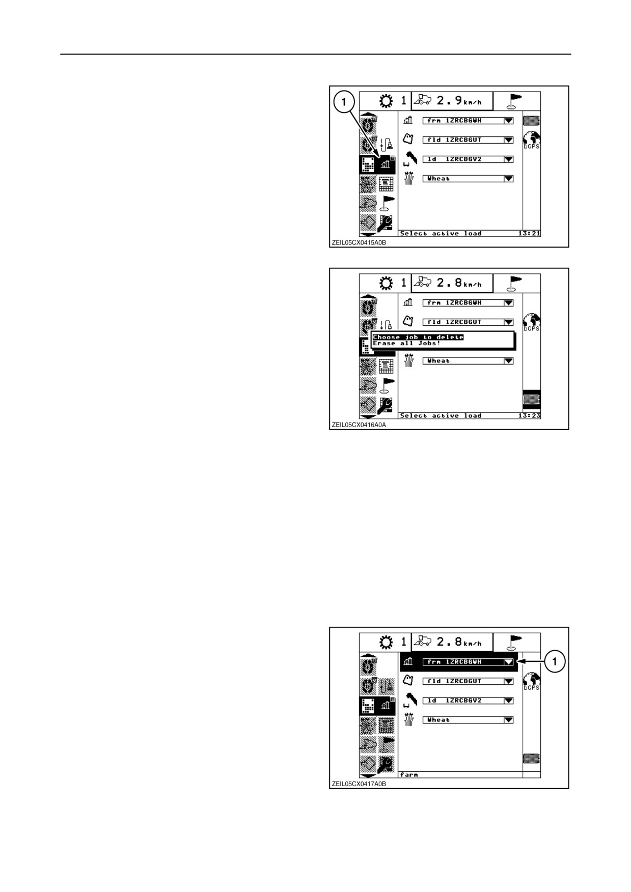
2. Select active load
The select active load screen is accessed by
selecting the “Select the active load” icon (1).
93
If no data card is inserted and the ’enter’ key is
pressed without highlighting any farm/field/load/crop
submenu (as shown in previous figure), the ”Job
delete sub-menu” will appear. Use this to delete a
single job (farm) or all jobs (farms) from the MDM
memory.
NOTE: When a data card is installed, nothing will
happen (no pop-up list appears) when the ”enter” key
is pressed.
Select or create Farm, Field, or Load name
NOTE: During harvest, the select/create function for
94
farm, field, load and crop type is locked out,
preventing the operator from attempting to change
any of the active items on this screen.
The following describes the steps to select or create
a farm. Steps to select or create a field or load are
similar.
With a PC card, there can be a maximum of 50 Farms
with 50 Fields per Farm and 50 Loads per field.
Without a PC Card installed, the InfoViewt flash is
limited to a maximum of 16 Loads divided between
any combination of 10 Farms and Fields.
Farm name
To change the active farm, select active load screen,
highlight the farm selector window (1), then press
”enter.”
95
2-63
SECTION 2 - CONTROLS, INSTRUMENTS AND OPERATION
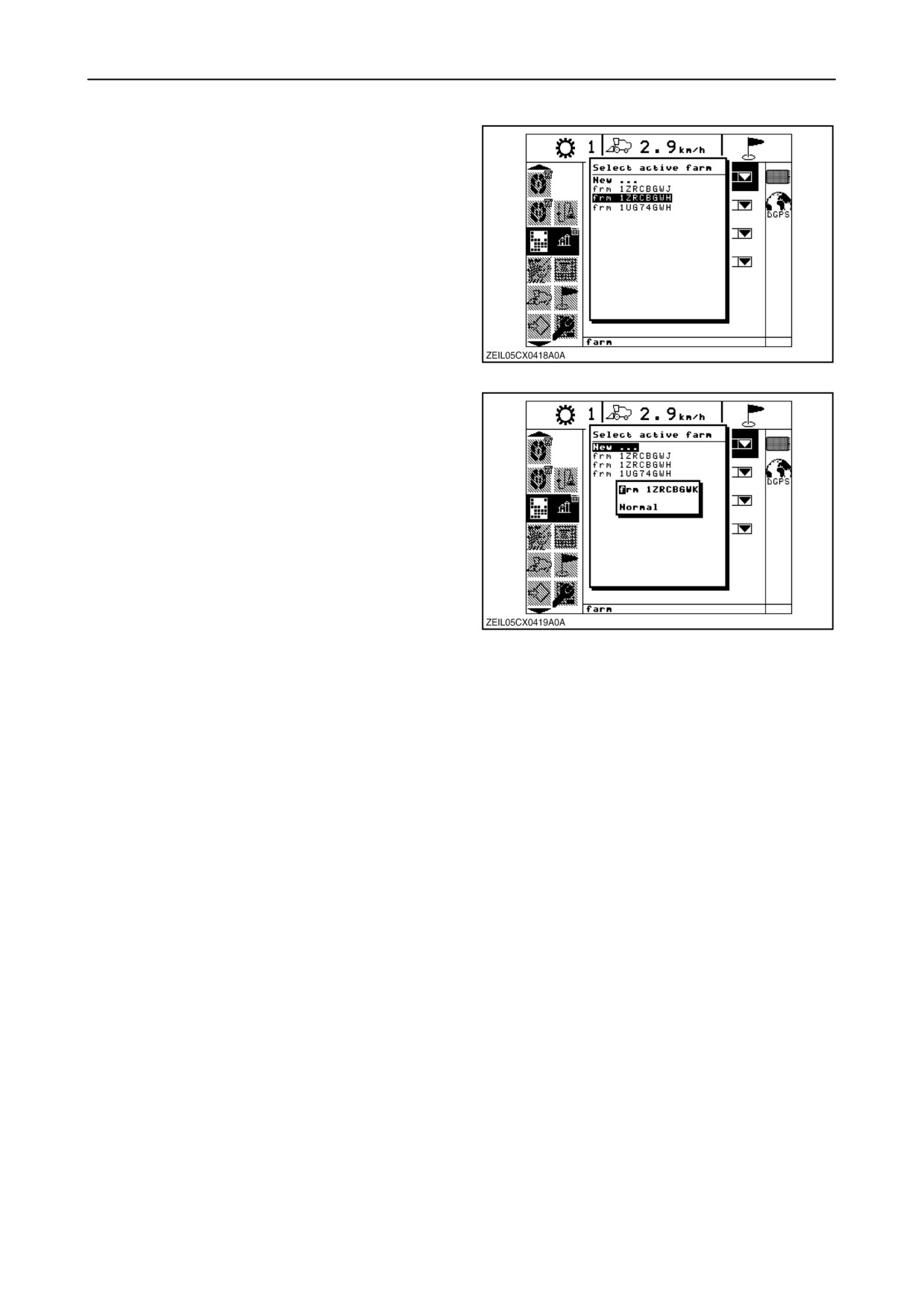
A drop down list will appear displaying the farm
names arranged in order they were created.
The first selection will always be ”New...” (Assuming
the maximum number of Farms has not been
reached). Using the up and down arrow keys,
navigate to the desired farm.
Pressing the ”enter” key selects the desired farm as
the active farm and returns to the farm selector
screen.
96
To create a new farm, highlight the ”New...” then
press ”enter”.
A pop-up window is displayed with the automated
system generated farm name.
Use the keypad to edit the name
(12 characters maximum).
Pressing the ”enter” key will save the name.
Pressing “ESC” will abort the edit process and return
to the select active farm drop down list without
creating a new farm.
97
The operator will not be allowed to create a new farm
if the maximum number of Farms is reached. The
“New...” selection will not be displayed. To regain the
ability to create new farms when the maximum
number has been reached, the data must be archived
to the desktop computer using the Precision Farming
Software. After the card data is archived, the .cnh file
on the card must be deleted using Windows Explorer.
NOTE: All data will be lost if the card is not archived
before deleting the .cnh file.
To use previously created Farm and Field names
after clearing a card, they will have to be exported
from the desktop computer to the card. This is
accomplished using the Device Setup Utility as
described in the Precision Farming Software
documentation.
2-64
SECTION 2 - CONTROLS, INSTRUMENTS AND OPERATION
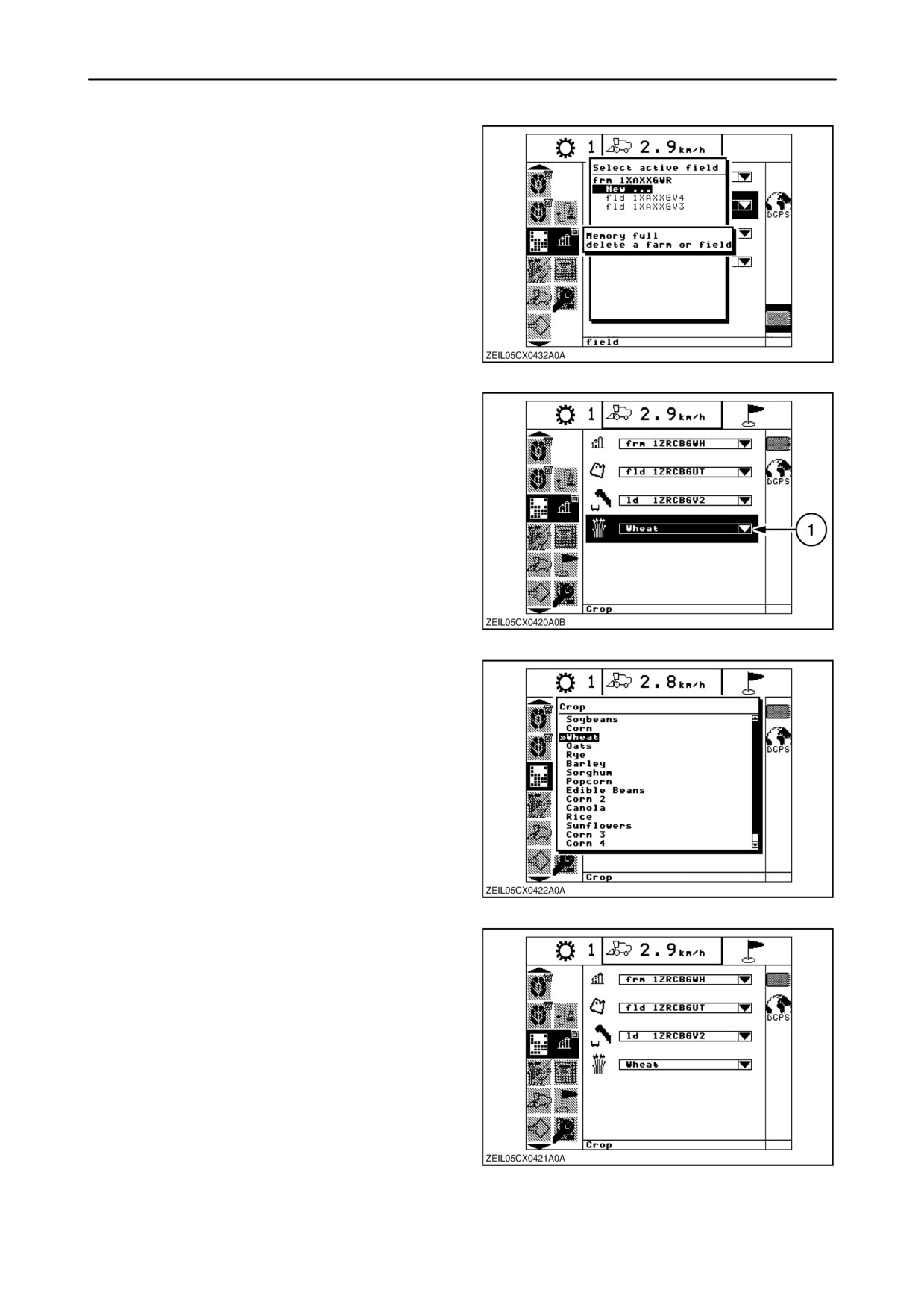
If there is no PC card present and the operator
attempts to create a new farm after the maximum
number of farms has been reached, the command will
be ignored and a ”Memory full - delete a farm or field”
(or a ”Memory full - delete a load”) pop-up will appear.
98
Crop type
The operator can select the crop type using the crop
selector.
To change the crop type, highlight the crop selector
window (1), then press ”enter”.
99
A pop-up window will appear displaying the crop
names.
Using the ”up” and/or ”down” arrow keys, navigate to
the desired crop.
Pressing the ”enter” key selects the desired crop type
associated with the active load and returns to the crop
selector screen.
100
After harvest data has been collected for the load, the
crop type function will be locked out, preventing the
operator from attempting to change the crop type
associated with the active load.
101
2-65
SECTION 2 - CONTROLS, INSTRUMENTS AND OPERATION
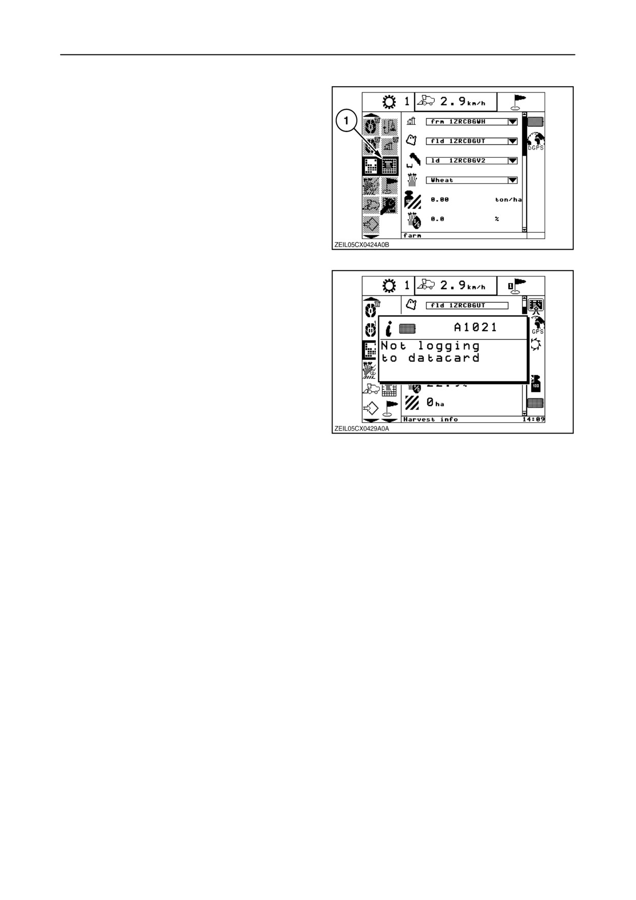
3. Harvest summary
The harvest screen is accessed by selecting the
harvest summary icon (1).
The harvest summary screen can be used to view
harvest history
(cumulative/average values for a
particular farm/field/load) for records residing on the
PC card or the InfoViewt flash.
102
If harvesting is attempted and no PC card is installed,
or if the card is removed during harvesting, a ”Not
logging to data card” pop-up message will appear.
103
2-66
SECTION 2 - CONTROLS, INSTRUMENTS AND OPERATION
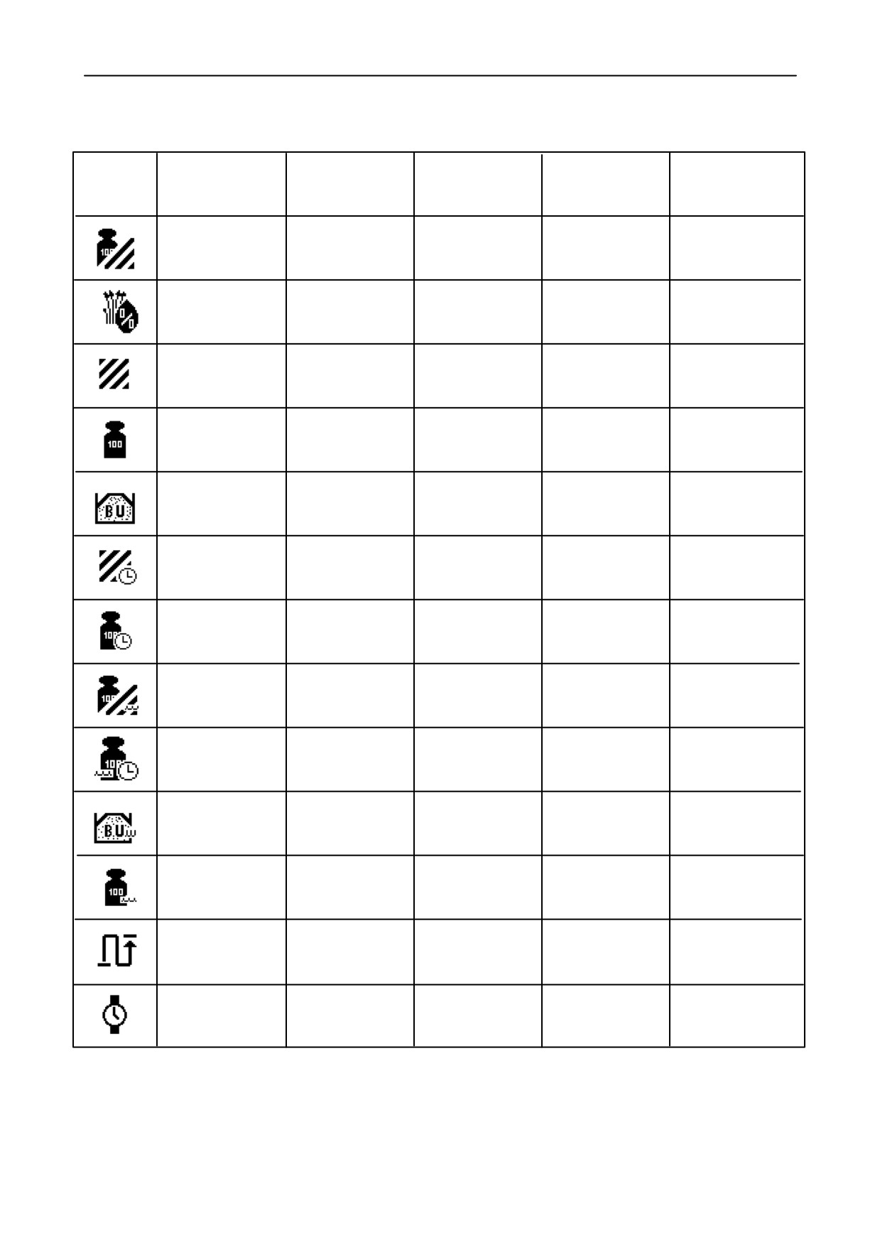
Harvest summary parameter list
Icon
Label
US format
US units
Metric format
Metric units
Yield - Dry
XXX.XX
bu/ac
XXX.XX
ton/ha
Moisture
XX.X
%
XX.X
%
Area
XXXX.XX
ac
XXXX.XX
ha
Dry mass
XXXXXXX
lb
XXXX.XXX
ton
Dry mass
XXXXXX.X
bu
XXXXXX.X
cu/meter
Volume
Harvest rate
XX.XX
ac/hr
XX.XX
ha/hr
Mass flow - Dry
XXXX.X
bu/hr
XXXX.XX
ton/hr
Yield - Wet
XXX.XX
bu/ac
XXX.XX
ton/ha
Mass flow - Wet
XXXX.X
bu/hr
XXXX.XX
ton/hr
Wet mass
XXXXXX.X
bu
XXXXXX.X
cu meter
Volume
Wet mass
XXXXXXX
lb
XXXX.XXX
ton
Trip distance
XXXXXXXX
XXXXX.XXX
km
ft
Time harvested
XX.XX
hours
XX.XX
hours
2-67
SECTION 2 - CONTROLS, INSTRUMENTS AND OPERATION
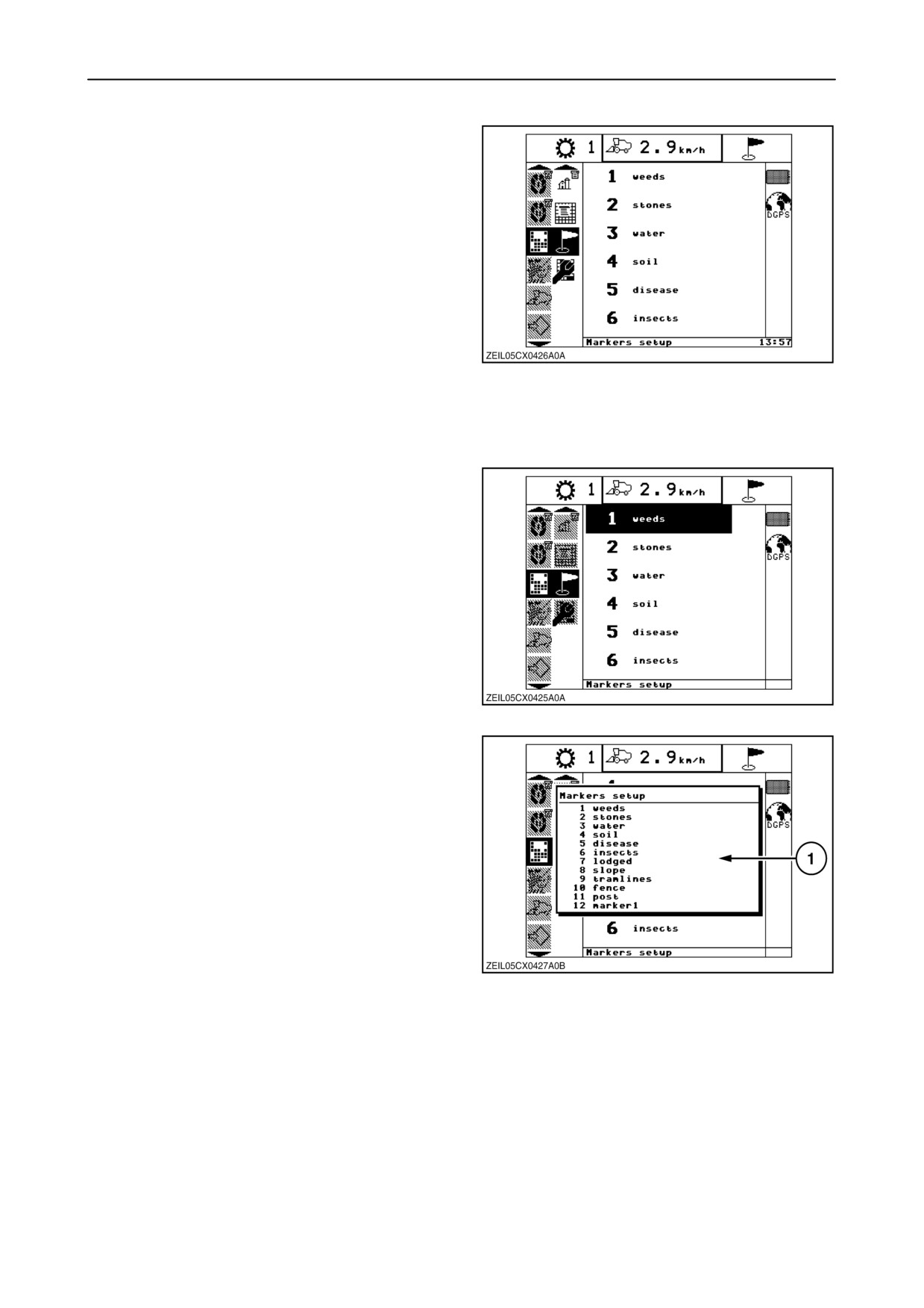
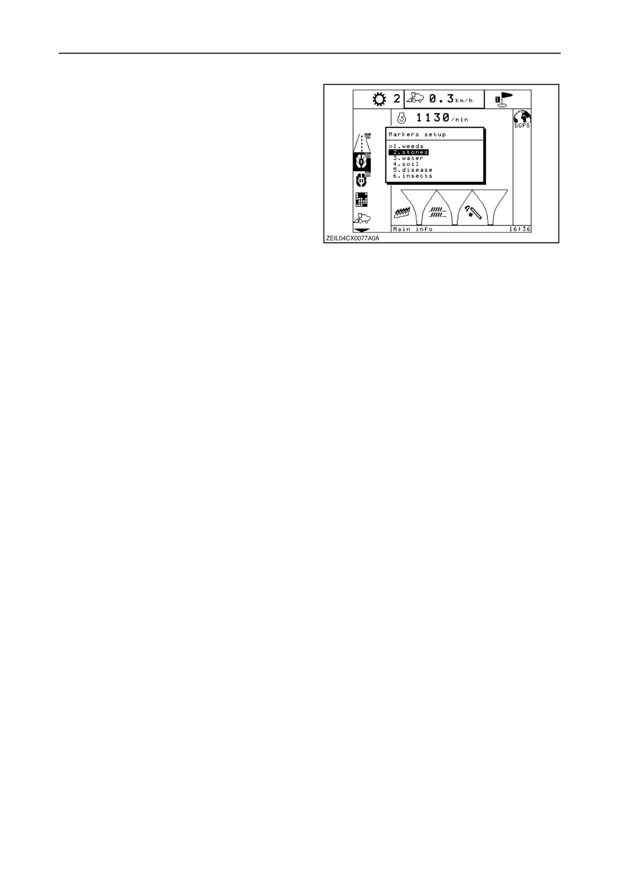
4. Marker setup
This sub-menu is only available when a data card is
installed.
When creating a yield map of the field being
harvested, markers can be set to identify the places
in the field with stones, lodged crop, ...
Up to six different types of markers (e.g. weed,
stones, other variety,...) can be used while creating a
yield map. There are
12 total marker names
available, any one of which can be assigned to the six
markers numbers on the display.
104
The actual assignment is displayed next to each
number. The assignment of markers to the numbers
can be changed.
To change the assignment of markers to the
numbers, proceed as follows:
1. Navigate to the marker setup screen, then press
the ”right” navigation key.
2. Select the number to be changed using the ”up”
or ”down” navigation keys.
3. Press ”enter”.
105
4. Pop-up screen (1) appears showing the different
markers available.
5. Select the desired type of marker with the ”up” or
”down” navigation key.
6. Press ”enter” to assign the selected marker to the
number.
106
2-68
SECTION 2 - CONTROLS, INSTRUMENTS AND OPERATION
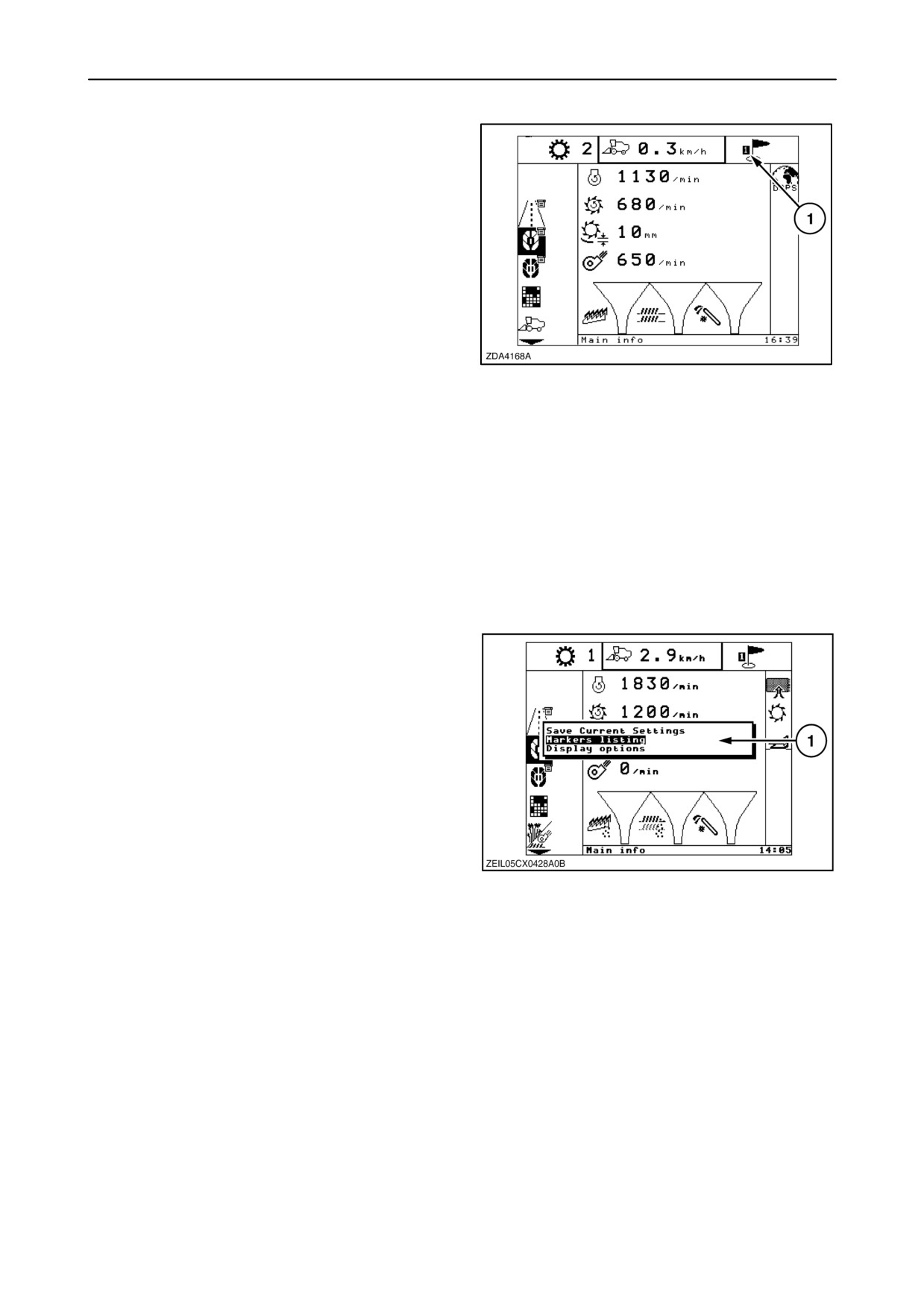
To identify an area in the field with a marker, press the
number assigned to that marker on the alphanumeric
keypad. The number pressed is shown in the
indicator bar near the ”data card installed” symbol at
“1”.
NOTE: Pressing a number (1 to 6) to identify markers
can be done when “Road info”, “Main info”, “Custom
info” or “Harvest info” menu or sub-menu is selected.
If another menu is selected by pressing a number, the
“Main info” menu will blinking.
Pushing again the number on the alphanumeric
keypad will cause the marking to stop. The number
107
shown in the indicator bar will disappear from the
screen.
NOTE: It is possible to enter more than one number
at the same time, if more than one marker needs to
be set at the same time in the field during harvesting.
NOTE: If you want to set a marker during harvesting
and you don’t remember the assignments, proceed
as follows:
1. Select “Road Info”, “Main info, or Custom info”
menu and press “enter”.
2. Pop-up screen (1) will appear.
3. Select “Markers listing”, using “up” navigation key
and press “enter”.
or
108
Press number ”0” on the alphanumeric keypad
when any menu is selected.
2-69
SECTION 2 - CONTROLS, INSTRUMENTS AND OPERATION
4. A pop-up screen will appear showing the six
numbers with the different markers assigned.
5. Press the number corresponding to the marker
you want to select, using the alphanumeric
keypad.
or
Using the “up” and/or “down” navigation keys to
select a marker and press “enter”.
If you will select more markers repeat this
procedure.
6. To delete a selected marker, select again this
marker and press “enter”.
or
109
Press the number corresponding to the marker
already selected.
NOTE: The double arrow in front of a marker on this
pop-up screen indicates this marker is already
selected.
2-70
SECTION 2 - CONTROLS, INSTRUMENTS AND OPERATION
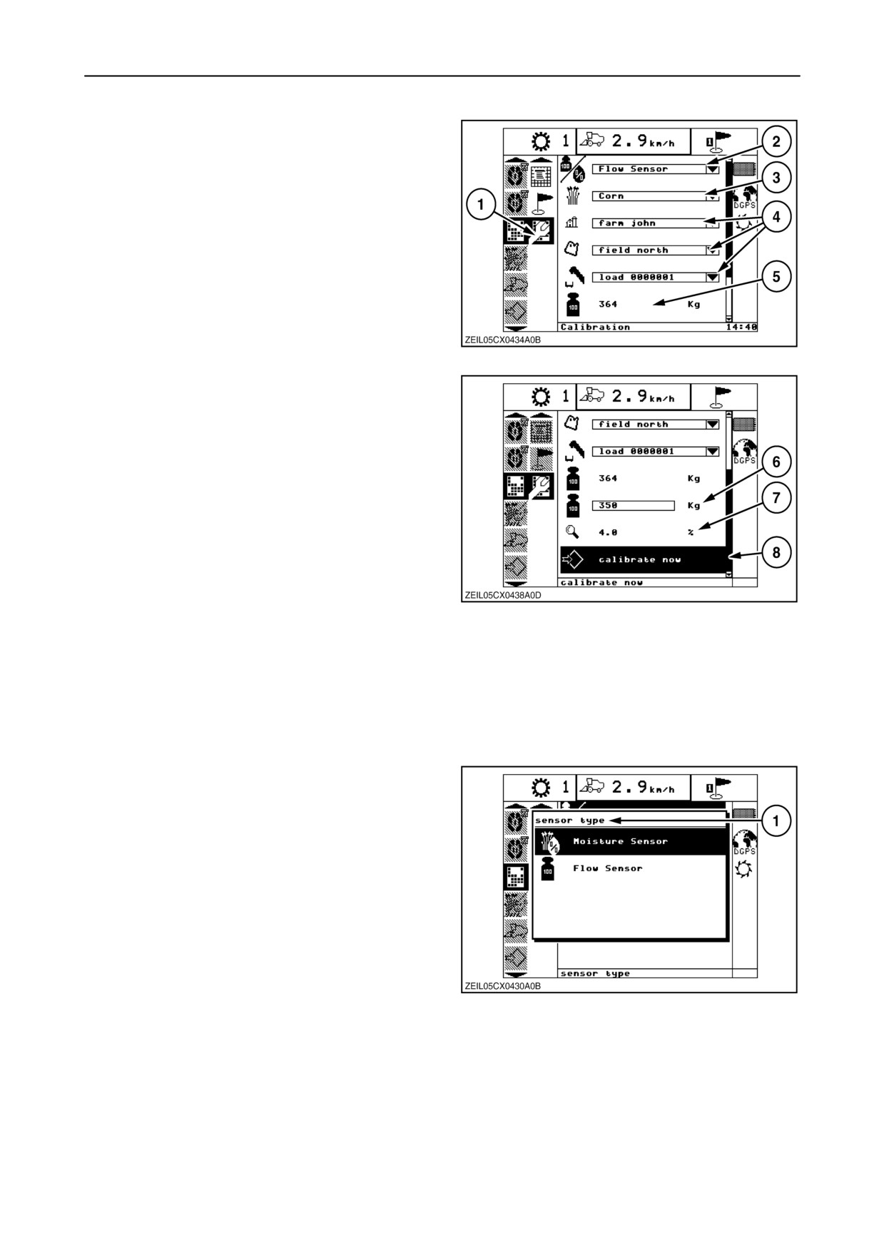
5. Calibration
The sensor calibration screen is accessed by
selecting the calibration icon (1).
The moisture sensor and the mass flow sensor must
be calibrated based on actual known measurements.
The moisture sensor calibration is always crop type
specific. The mass flow sensor calibration is global,
across all crop types. It is also stored in each load.
The calibration screen allows the operator to:
110
• Select a sensor type to calibrate (2).
• Select a specific crop to calibrate (3).
• Select a specific farm, field and load (4).
• View the machine measured value of weight or
moisture (5) (depending on sensor type selected)
for the selected data set.
• Enter the manually measured ’actual’ value of
weight or moisture (6), (depending on sensor
type selected) for the selected data set.
111
• View the percent error (7) between the measured
and actual values for the selected data set.
• Trigger the generation of calibration values for the
selected data set and newly created data sets (8).
Sensor selection
From the calibration screen, select the sensor type
(1) and press ”enter”. A pop-up list will appear.
Use the up and down arrow keys to navigate to the
flow or moisture sensor to be calibrated.
Press the ”enter” key to select the sensor.
Select the desired dataset (crop type, farm, field and
load) to be calibrated. This selection procedure
operates the same as on the “Select active load”
screen.
112
NOTE: The following describes the steps to setup
and perform crop calibration. Steps to setup and
perform the moisture sensor calibration are similar.
2-71
SECTION 2 - CONTROLS, INSTRUMENTS AND OPERATION
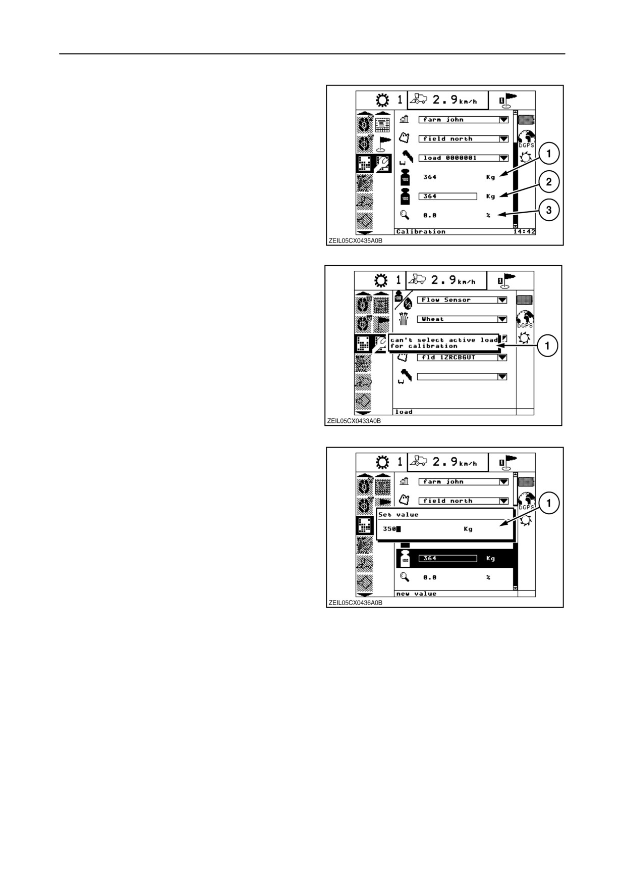
Crop calibration setup
Measured load weight (1) is labeled ”value” at the
bottom of the screen.
The actual load weight (2) is labeled ”new value”.
The load error (or percent difference) (3) between
measured and actual values is labeled “deviation”.
Upon initial selection of a dataset, the measured and
actual load weights are equal to each other and the
load error is 0.0%.
113
The current, active load cannot be used as a
calibration load.
The operator receives a pop-up window (1) informing
of this conflict and no load is selected.
114
From the calibration screen, select the actual load
weight via the navigation arrow keys; then press
”enter”. A pop-up window (1), is displayed which
allows the operator to input the actual load weight via
the numeric keypad, then press ”enter”.
Also the load to be calibrated must contain valid
harvest data. If it does not, it will not be displayed on
the load drop down list.
115
2-72
SECTION 2 - CONTROLS, INSTRUMENTS AND OPERATION
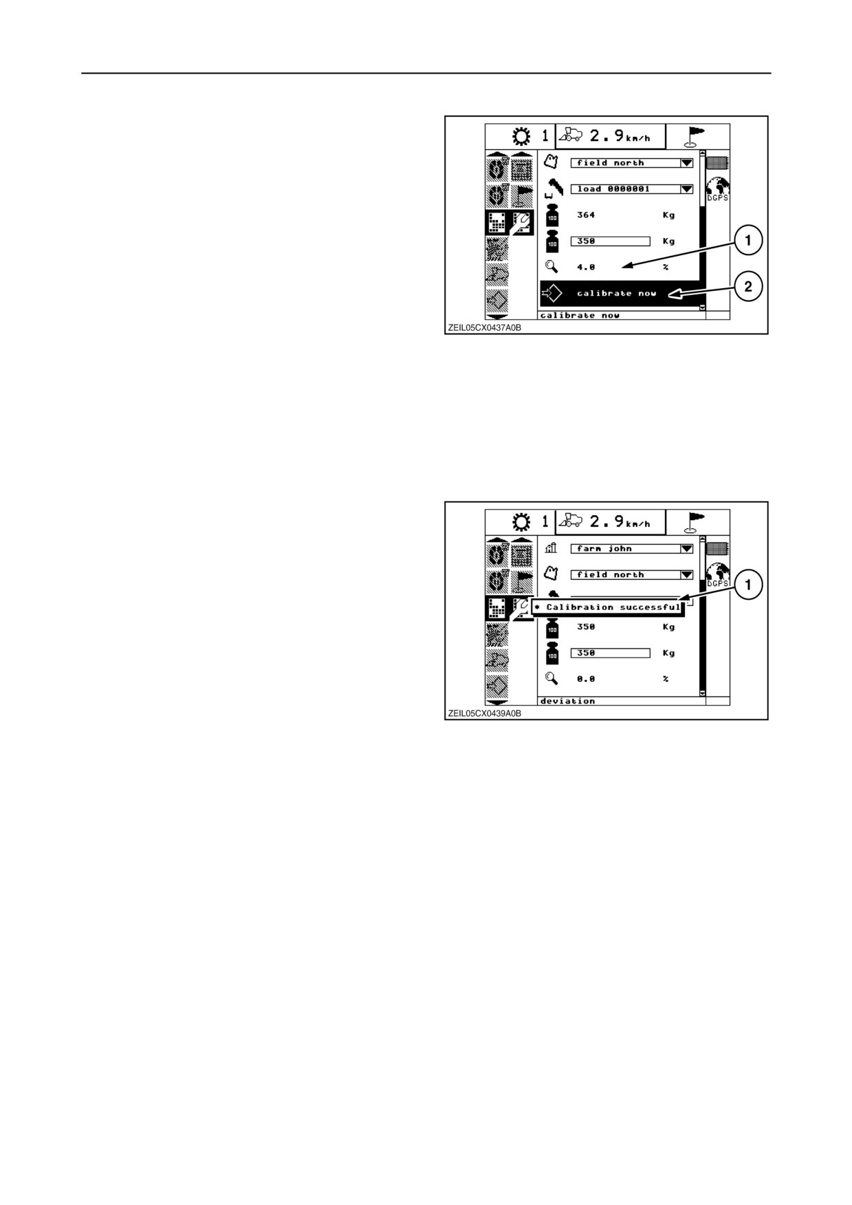
To reflect the difference between the two weights, the
load error (1) changes from 0.0% (assuming the
difference is at least or greater than 0.1%). The
”calibrate now” selection (2) is now displayed below
load error.
Perform crop calibration
NOTE: Calibration can only be performed with the
straw elevator disengaged.
Select the ”calibrate now” (2) and press ”enter”.
This load is tagged as the
”Calibration load”
116
(”Calibration load” flag set) and locked to prevent the
addition of any more measured weight.
The “calibration load” flag will remain set for loads
previously used for calibration and these loads will
remain locked. However, only the load currently
selected on this Calibration screen is used for the
current calibration process.
A ”Calibration successful” pop-up window (1), is now
displayed and the ”calibrate now” selection is no
longer present.
Additionally, the measured value now reflects the
actual value and the load error returns to 0.0%.
NOTE: After calibration of a load, it is no more
possible to continue with this load, a new active load
needs to be selected.
117
2-73
SECTION 2 - CONTROLS, INSTRUMENTS AND OPERATION
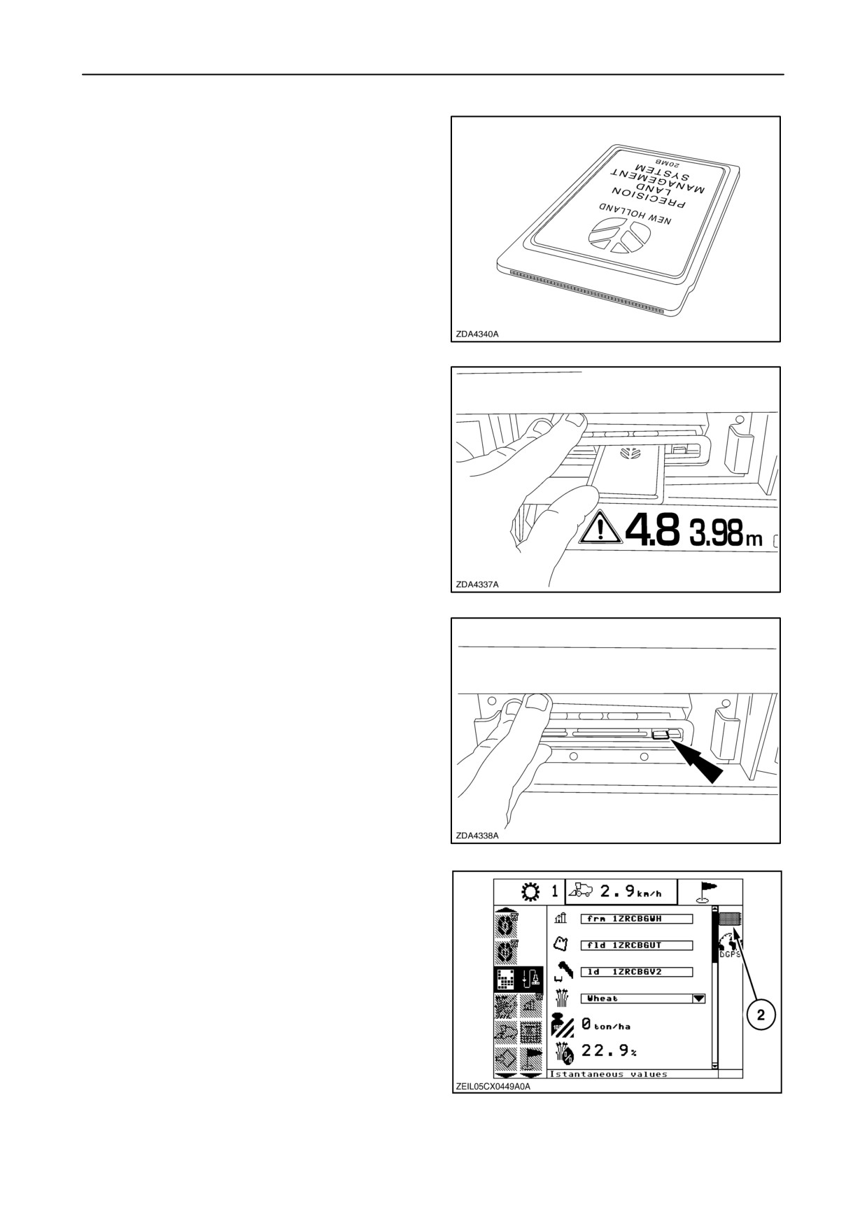
DATA LOGGER (IF INSTALLED)
To keep all the field data is it necessary to insert a data
card in the data logger.
118
To install a data card correct in the data logger,
proceed as follows:
1. Install the data card with the New Holland logo on
the top side and with the connection holes first
into the data logger.
119
2. Push the data card into the logger until the button
is extended out.
3. Close the data logger.
120
If icon
2 appears on the Harvest info screen
means that the data card is present in the data
logger.
121
2-74
SECTION 2 - CONTROLS, INSTRUMENTS AND OPERATION
To check how many percent of the total memory
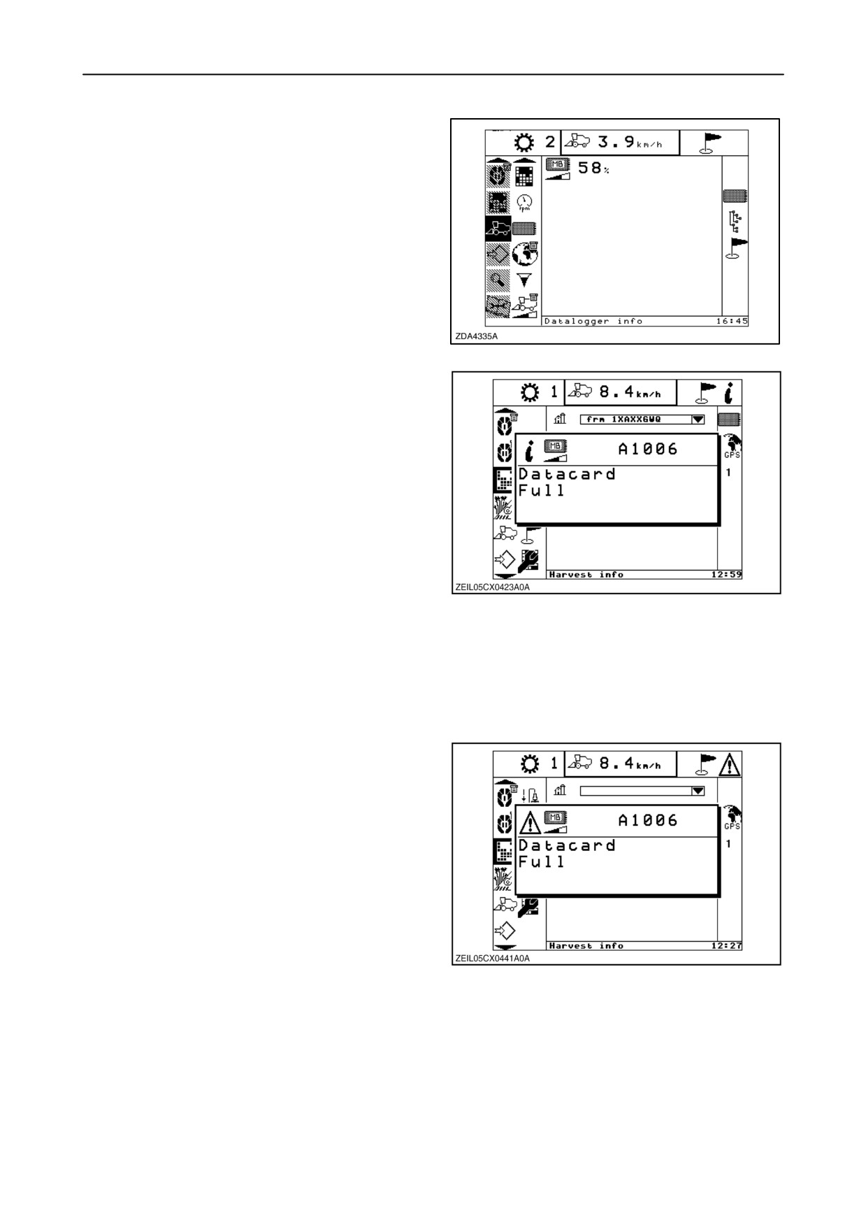
capacity is still available on the data card, select
menu
“combine information” screen and
sub-menu item
“data logger”
, using the
navigation keys.
122
When the data card reaches 5% remaining storage
capacity, a level 1 ”Datacard Full” warning will be
received with an audible alarm.
It will clear itself automatically and reappear every
four minutes.
To regain card space, the data must be archived to
the desktop computer using the Precision Farming
Software. After the card is archived, the .cnh file on
the card must be deleted using Windows Explorer.
NOTE: All data will be lost if the card is not archived
before deleting the .cnh file.
123
To use previously created Farm and Field names
after clearing a card, they will have to be exported
from the desktop computer to the card. This is
accomplished using the Device Setup Utility as
described in the Precision Farming Software
documentation.
When the data card reaches 3% remaining storage
capacity, a level 2, ”Datacard Full” warning will be
received with an audible alarm. It will stay on screen
until acknowledged by the operator. While on screen,
audible alarm will sound every 30 seconds. Once
acknowledged, it reappears every 2 minutes. Data
from the card should be archived and unwanted files
removed to regain space as described in the previous
paragraph.
124
2-75
SECTION 2 - CONTROLS, INSTRUMENTS AND OPERATION
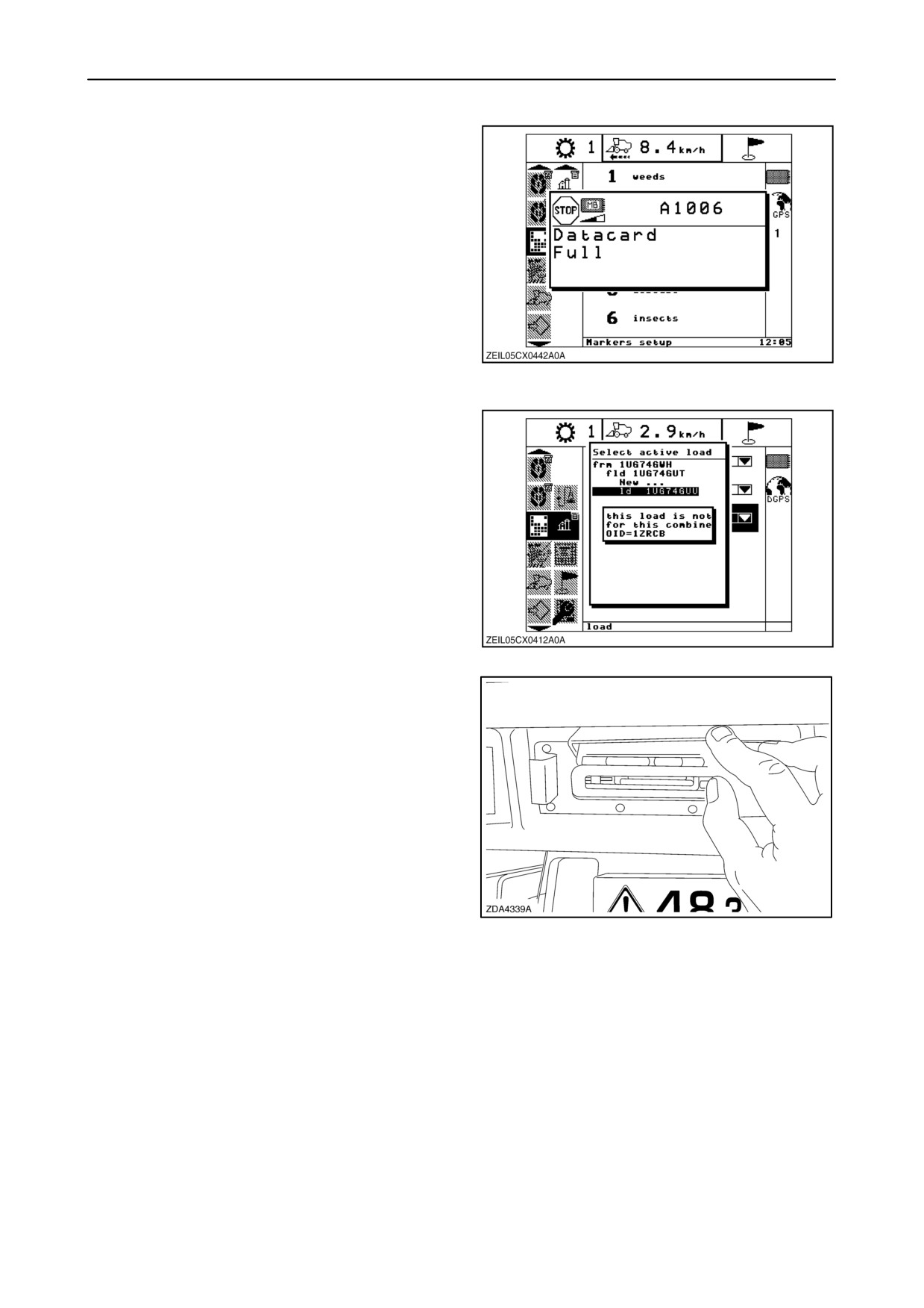
When the data card reaches 1% remaining storage
capacity, a level 3, ”Datacard Full” warning will be
received with an audible alarm.
It will stay on screen until acknowledged by the
operator.
While on screen, audible alarm will sound every 30
seconds.
Once acknowledged, it reappears every 1 minutes.
When the card becomes completely full, data logging
will be disabled until data from the card is archived
and unwanted files removed to regain space as
125
described in the previous paragraph.
NOTE: When a data card from another combine will
be used, a message appears: “This load is not for this
combine”.
126
To remove the data card, proceed as follows:
1. Open the data card door and push on the button.
2. Remove the data card.
IMPORTANT: Be careful with your data card, this
card contain all the field information.
NOTE: Every time the combine ignition switch is
placed in the ON position, a new [date stamp].log file
is created. These log files can be copied or moved to
a personal computer using a PCMCIA card slot.
127
2-76
SECTION 2 - CONTROLS, INSTRUMENTS AND OPERATION
CALIBRATIONS FOR YIELD MONITORING OR MAPPING
The different calibration procedures, necessary for
good functioning of the yield monitoring or mapping
system and to obtain correct loads on the
InfoViewt, are:
• Travel speed (*)
• Maximum stubble height(*)
• Grain flow sensor
• Moisture sensor
(*) see calibrations for basic operation
NOTE: To perform a calibration refer also to
“Calibrations for basic operation”
IMPORTANT: Check if the following settings are
done to assure correct functioning of the yield
monitoring or mapping.
• Header width (setting with grain header)
• Header usage (setting with grain header)
• Rows in use (setting with maize header)
• Row distance (setting with maize header)
2-77
SECTION 2 - CONTROLS, INSTRUMENTS AND OPERATION
(DIFFERENTIAL) GLOBAL POSITIONING SYSTEM - (D)GPS (IF INSTALLED)
The GPS receiver uses differential GPS (DGPS) to
achieve accuracy to less than one meter (yard).
DGPS requires two or more receivers. One receiver,
called the reference or base station, is located at a
known point to determine the GPS measurement
errors. The reference station broadcasts correction
values, which are used by the mobile GPS receivers
to improve the accuracy of the GPS signal. When this
signal cannot be received by the GPS receiver
(because it’s operating to far from the reference
station) the receiver can use the satellite correction
signal. Satellite differential GPS signals are sent from
the reference station through a satellite transponder
to users within the view of satellite.
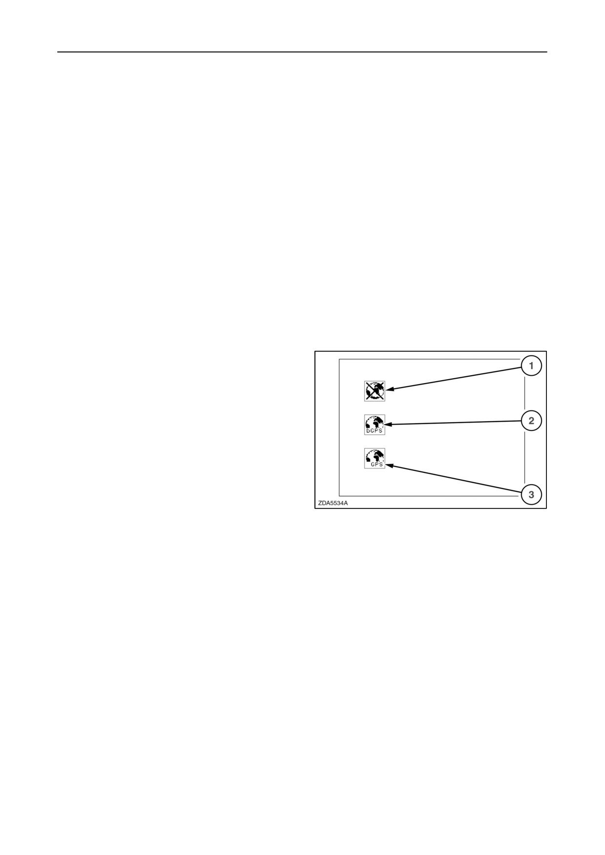
The icon appears in the status bar and shows if there
is (D)GPS reception or not.
1. No reception
2. DGPS reception
3. Only GPS reception (blinking)
128
2-78
SECTION 2 - CONTROLS, INSTRUMENTS AND OPERATION
GPS status+configuration screen
This screen gives the possibility to set up the GPS
receiver. By factory setting the receiver is set up to
receive the GPS signal and every beacon differential
correction signal. If the combine is operating far from
the reference station it can happen that differential
correction gets lost frequently. In this case it is
advised to take a subscription on a satellite
differential GPS signal.
For example: OMNISTAR.(www.omnistar.com)
To enter the GPS configuration screen to set-up the
receiver for a particular satellite, proceed as follows:
1. Select the combine info screen in the menu bar
by using the up and down navigation keys.
2. A sub-menu will appear next to the menu bar.
3. To enter that sub-menu, press the
”right”
navigation key.
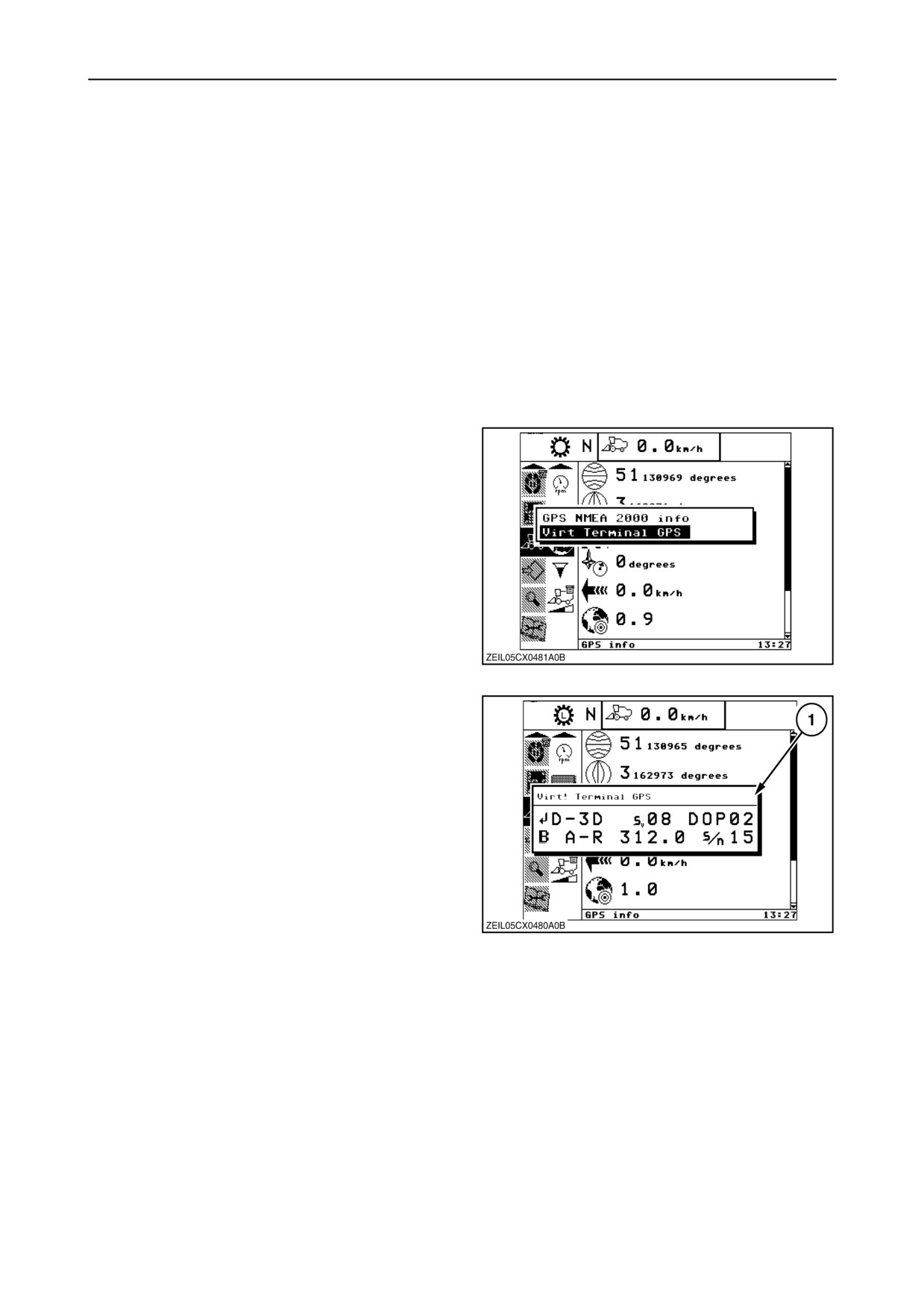
4. Select “GPS info”, by using the up and down
navigation keys and press “enter”. A pop-up
screen appears.
5. Select “Virtual Terminal GPS” and press “enter”.
129
6. Pop-up screen (1) appears.
The contents depend on the selected DGPS data
source.
D-XX = Differential GPS reception
G-XX = Only GPS reception
X-2D = 2-D position only (latitude/longitude)
X-3D = 3-D position/ coordinates
(latitude/ longitude+ height above the sea level)
Sv XX = Number of satellites tracked
(more = better)
130
DOP = For diagnostics/ troubleshooting only
B = Receiver is using Beacon DGPS
A-R = Beacon operating mode
312.00 = Beacon frequency, varies depending
the beacon used
S/n XX = Signal / noise ratio (quality of signal),
(higher = better)
2-79

SECTION 2 - CONTROLS, INSTRUMENTS AND OPERATION
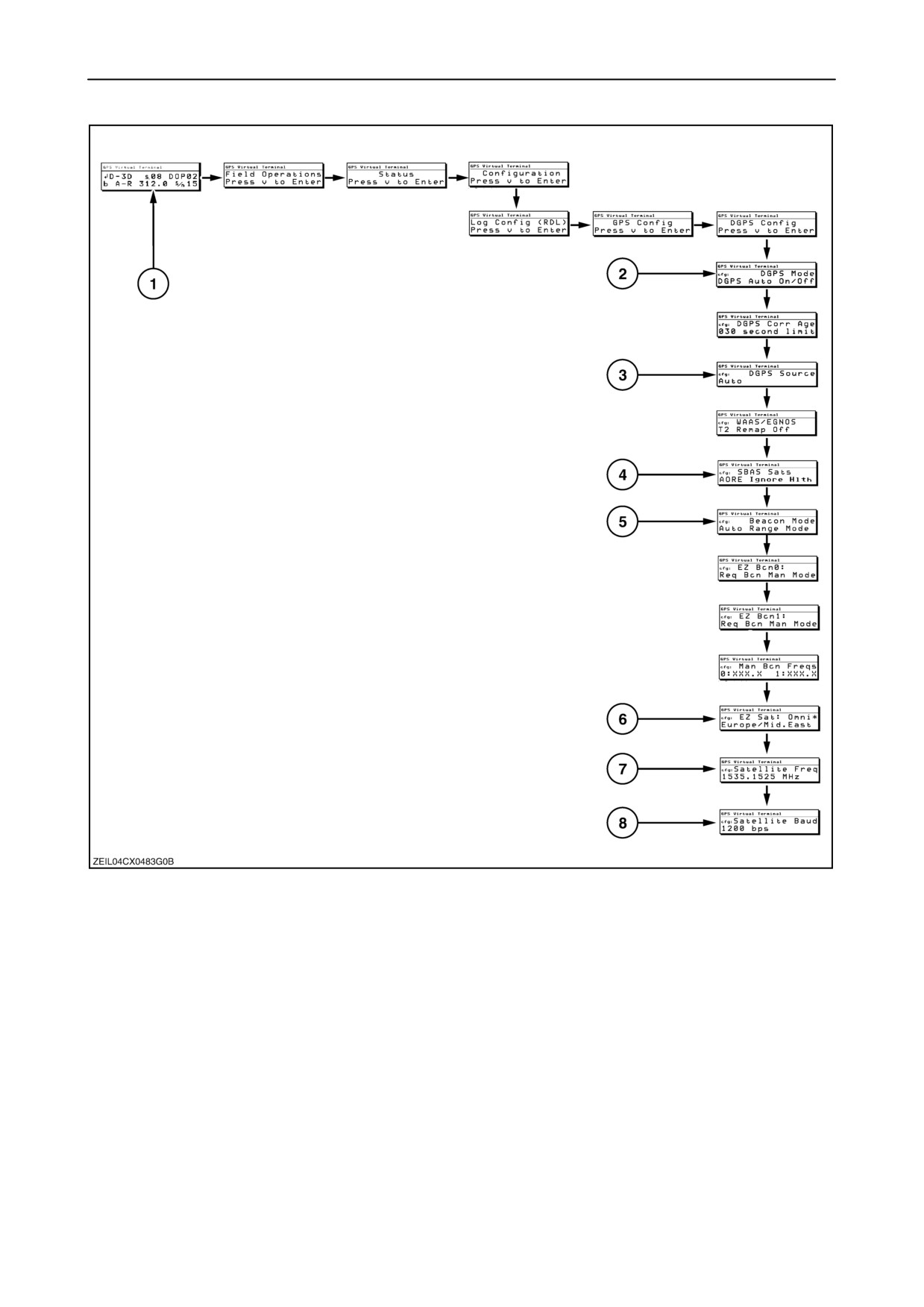
7. Go to screen (2) (fig. 131), using the right and
down navigation keys.
NOTE: The direction (arrow) of the new screen
compared to the screen before gives the direction of
the navigation key to use.
8.
Select the “DGPS mode” screen (2) (fig. 131) by
using the right navigation key. Using the up and
down navigation keys gives the possibility to
select the mode.
• DGPS Only
• DGPS Manual Off
• DGPS Auto On/Off
9.
Press “enter” to confirms the selection.
10. Select the “DGPS source” screen (3) (fig. 131)
by using the right navigation key. Using the up
and down navigation keys gives the possibility to
select the source.
• Omnistar
• Beacon Only
• WAAS/ EGNOS Only
• Auto
11. Press “enter” to confirms the selection.
12. Select the screen (4) (fig. 131) by using the right
navigation key. Using the up and down navigation
keys gives the possibility to select the status of
the satellite.
NOTE: The table below shows the status for each
satellite that needs to be selected.
(The satellite will be visible as name or number)
Satellite
Status
AORE (120)
Ignore Hlth
ARTE (124)
Ignore Hlth
IORW (126)
Ignore Hlth
IOR (131)
Disabled
Others
Disabled
13. Press “enter” to confirm the selection.
2-80
SECTION 2 - CONTROLS, INSTRUMENTS AND OPERATION
14. Select the “Beacon mode” screen (5) (fig. 131)
by using the right navigation key. Using the up
and down navigation keys gives the possibility to
select the location.
• Auto range mode
• Auto power mode
• Disabled mode
• Manual frequency mode
15. Press “enter” to confirm the selection.
16. Select the screen (6) (fig. 131) by using the right
navigation key. Using the up and down navigation
keys gives the possibility to select the location.
• Europe / Middle East
• South America / Asia
• North America East
• North America West
• Optus - Aus / NZ
• Asia / South America
• Africa
17. Press “enter” to confirm the selection.
NOTE: Go to screen (7) and (8) to check the satellite
frequency and the baud rate.
Fore more information, refer to the operator’s manual
“TRIMBLE NH 134”.
18. To go back to home screen (1) (fig. 130), press
“esc” several times.
2-81
SECTION 2 - CONTROLS, INSTRUMENTS AND OPERATION
131
2-82
SECTION 2 - CONTROLS, INSTRUMENTS AND OPERATION
V AUTOMATIC CROP SETTINGS
GENERAL
The Automatic Crop Settings (ACS) system allows
Each mode can have one of three types of settings
the combine operator to select up to three combine
assigned to it. “Default” which sets all settings to the
operating modes for each crop. There are two
factory settings for that crop; “User” which allows the
working modes and one mode that will be selected
user to set the parameters; and “None” which will not
automatically when traversing the headland. The two
change any parameter when a different mode is
working modes are easily selected (swapped) during
selected.
operation via the Automatic Crop Settings tumbler
switch on the right-hand module. Double-clicking the
Crops have predefined default factory sets. These
resume button on the MFH, to lift the header using
can be changed by the operator to suit every
automatic header height, also activates the Headland
harvesting condition and saved as user sets. The
mode, adjusting corresponding machine settings.
default factory settings can be restored if desired.
An example of how these functions can work together
is: Mode 1 is the factory set values, which the
operator has confirmed to work well in standing crop.
However, if losses increase in lodged areas of the
field, the operator can make adjustments and save
them as Mode 2. The operator can then switch the
Automatic Crop Settings tumbler switch to Mode 2
when entering a lodged area and to Mode 1 for
standing crop. In addition the operator could reduce
the fan speed in one of these modes to reduce losses
at the headlands and save this as the Headland
mode. If the operator does not want the combine to
adjust at the headland, he sets the Headland mode
to None and the combine will continue to use the
current mode at the headlands.
2-83
SECTION 2 - CONTROLS, INSTRUMENTS AND OPERATION
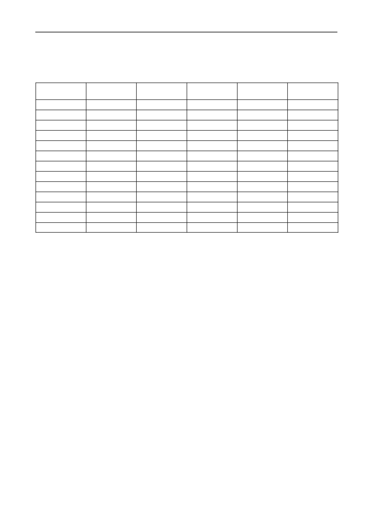
Factory default values
(Automatic Crop Settings)
Crop
Drum speed
Concave clear-
Fan speed
Upper sieve
Lower sieve
ance
Soybeans
550
20 mm
750
11 mm
7 mm
Corn (Maize)
360
25 mm
850
12 mm
10 mm
Wheat
800
10 mm
750
11 mm
5 mm
Oats
740
10 mm
570
11 mm
5 mm
Rye
850
10 mm
700
11 mm
5 mm
Barley
850
10 mm
750
11 mm
5 mm
Sorghum
640
10 mm
770
10 mm
6 mm
Popcorn
360
25 mm
850
12 mm
10 mm
Beans
340
27 mm
1000
15 mm
11 mm
Canola
500
24 mm
450
8 mm
3 mm
Rice
680
20 mm
650
11 mm
5 mm
Sunflowers
300
27 mm
600
11 mm
7 mm
Peas
340
20 mm
1000
10 mm
11 mm
NOTE: “Corn 2, 3 and 4” and using the same settings of “Corn”.
2-84
SECTION 2 - CONTROLS, INSTRUMENTS AND OPERATION
Activating the ACS
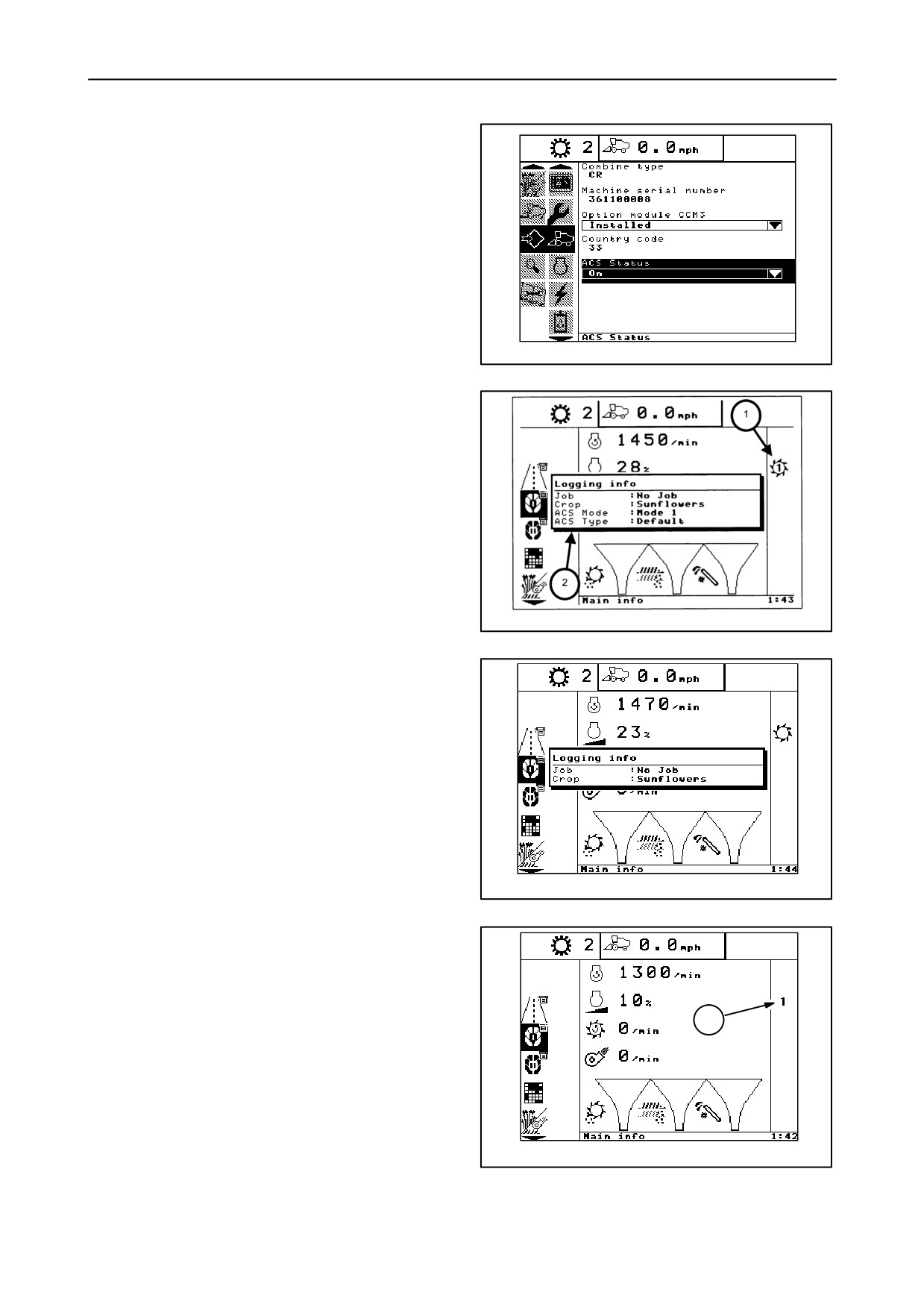
1. The ACS is activated from the “Combine” page of
the “Configuration info” screen.
NOTE: This configuration can also be placed on any
of the operator configurable screens (Road info, Main
info, and Custom info).
20040163
132
2. When the ACS is activated, and the threshing is
engaged, the “Threshing engaged” icon 1 will
encircle the ACS Mode (1, 2, H) icon and the
“Logging Info” pop-up window 2 will appear for 5
seconds.
The ACS modes are:
• Mode 1 = 1
• Mode 2 = 2
• Headland = H
NOTE: The ACS mode icon will be displayed
whenever the ACS is activated, whether or not the
20043685
thresher is engaged.
133
NOTE: If the ACS is off, the center of the threshing
engaged icon will be empty and the ACS mode and
ACS type lines will not be displayed on the pop-up
window.
20040165
134
NOTE: The ACS mode icon 1 will be displayed
whenever the ACS is activated, whether or not the
thresher is engaged.
1
20040184
135
2-85
SECTION 2 - CONTROLS, INSTRUMENTS AND OPERATION
Saving ACS user settings
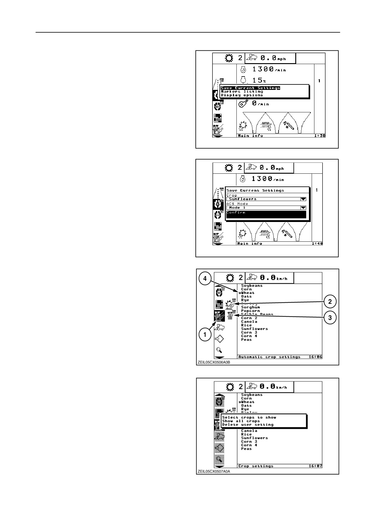
1. To save ACS user settings from the “Main info”,
“Combine info” or “Road info” screens, highlight
one of these menus and press “enter”.
The “Save Current Settings” option is the first
item in the list and is initially highlighted. Press
“enter” again.
20040174
136
2. Pressing “enter” a third time will save the settings
for the current crop and ACS mode. If the
operator desires to save the settings for a
different crop or ACS mode, they can be
accessed from the drop down menus.
20040175
137
Crop settings and current settings
1. Select the Automatic Crop Settings screen 1 in
the menu bar. Two sub-menu symbols will
appear, current settings 2 and crop settings 3.
Crop settings
NOTE: The crop settings screens allow the operator
to edit the crop list as well as edit and save machine
settings.
1. Select the crop settings sub-menu 3 to display the
list of crops.
138
2. The double arrow 4 to the left of a crop indicates
the crop selected for the current job (fig. 138).
3. Press “enter” to display the pop-up window.
The edit options are:
• Select crops to show
• Show all crops
• Delete user setting
139
2-86
SECTION 2 - CONTROLS, INSTRUMENTS AND OPERATION
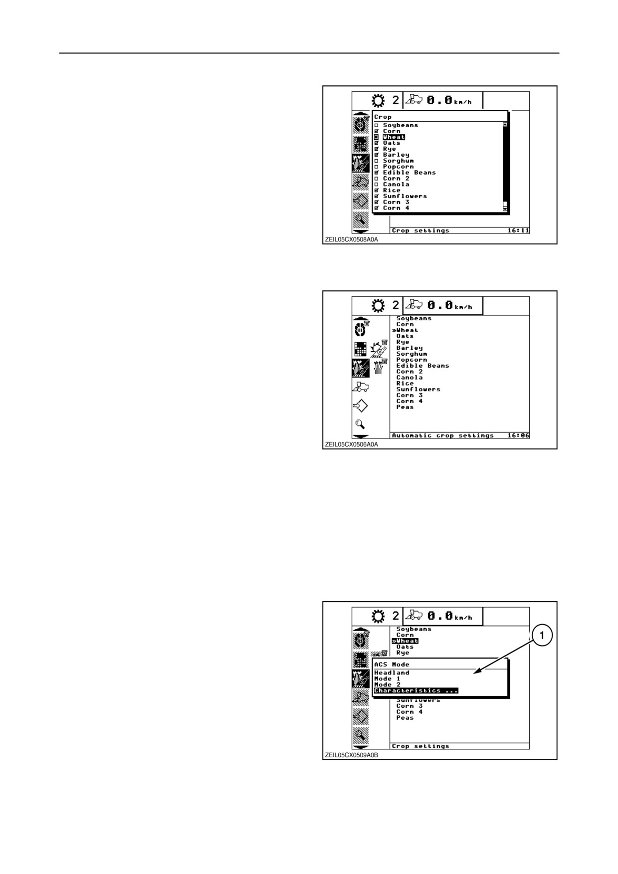
4. To display only the crops the combine will be used
to harvest, select “Select crops to show” and
press “enter”.
5. The pop-up screen will list all 16 factory defined
crops. Use the
“up” and
“down” navigation
buttons to navigate through the list.
Use the “left” navigate button to select or deselect
a crop. Once the desired crop is selected, press
the
“enter” key. The selected crop will be
displayed on the Automatic Crop Setting and
Harvest info screens.
140
The different crops that can be selected are:
1. Soybeans
2. Corn
3. Wheat
4. Oats
5. Rye
6. Barley
7. Sorghum
8. Popcorn
9. Edible Beans
10. Corn 2
11. Canola
12. Rice
13. Sunflowers
141
14. Corn 3
15. Corn 4
16. Peas
Each crop has its own settings which are used to
calculate the ”dry” weight and the ”volume”.
(“volume”= only when US units are selected)
These settings are initially set at the factory and are
mentioned in a table (see further).
These setting can be changed. Proceed as follows:
1. Select the crop of which the setting are to be
changed and press “Enter”.
2. Pop up screen 1 appears.
3. Select “Characteristics ...” and press “enter”.
142
2-87
SECTION 2 - CONTROLS, INSTRUMENTS AND OPERATION
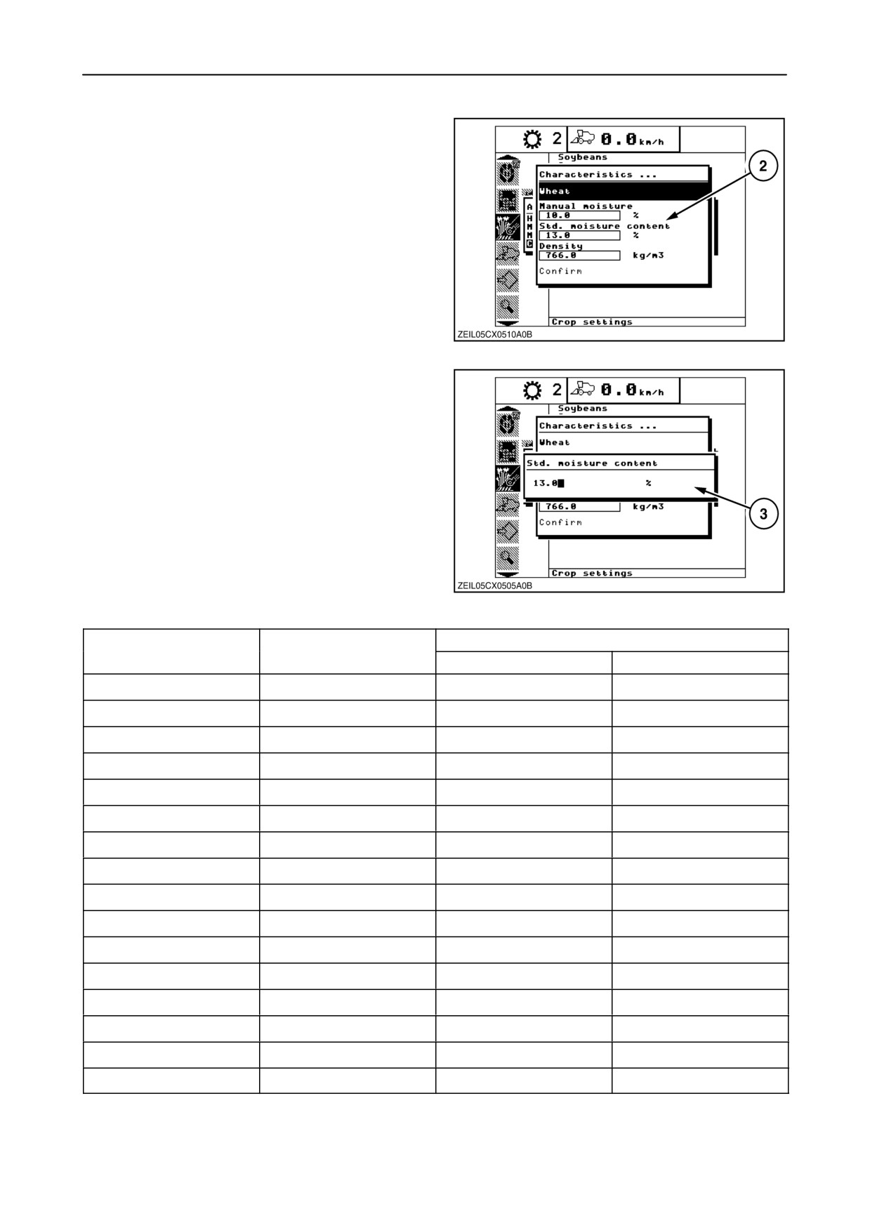
4. Pop-up screen 2 appears.
5. Select the
”Manual moisture”,
“Standard
moisture content” or the ”Density” setting and
press “enter”.
143
A pop-up screen 3 is displayed which allows the
operator to input the actual moisture content or the
density via the numeric keypad, then press “enter”.
NOTE: The factory setting for the different crop types
regarding “Standard moisture content” and “Crop
density” are listed below.
144
Crop
Standard moisture (%)
Crop density
kg/m3
lb/bu
Soybeans
13.0
766
59
Corn (Maize)
15.5
709
54
Wheat
13.0
766
59
Oats
14.0
426
33
Rye
14.0
709
54
Barley
14.0
624
48
Sorghum
13.0
709
54
Popcorn
14.0
766
59
Edible Beans
14.5
795
61
Corn 2
15.5
709
54
Canola (Rapeseed)
10.0
681
52
Rice
14.0
568
44
Sunflowers
6.0
568
44
Corn 3
15.5
709
54
Corn 4
15.5
709
54
Peas
10.5
766
59
NOTE: “Corn 2, 3 and 4” and using the same settings of “Corn”.
2-88
SECTION 2 - CONTROLS, INSTRUMENTS AND OPERATION
ACS mode screen
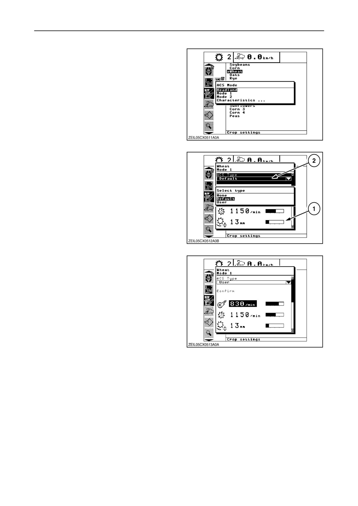
1. This screen is used to choose among the three
modes. Headland is the setting the combine will
adjust to when the header is raised at the end of
the crop when using the automatic header height.
Mode 1 and Mode 2 are two different settings the
operator can switch between, using the
Automatic Crop Settings tumbler switch.
Highlight the desired mode, then press “enter”.
145
2. A pop-up screen 1 appears.
3. Highlight the ACS Type 2 and press “enter” to
display the type selection pop-up.
• None - This selection will not change any
combine settings from the previously
selected mode. The values shown will be a
string of #s
• Default - Factory settings for that crop. If this
is a custom crop, the default values for wheat
are used.
• User - User will be able to change the
settings.
146
4. To change a setting, highlight the setting. Modify
the value using either the +/- key or the numeric
keypad. To save the value, select “Confirm” and
press “enter”.
NOTE: The machine will adjust speeds to the new
setting only if the thresher is engaged and the engine
speed is greater than 1800 RPM.
147
2-89