New Holland CX720, CX740, CX760, CX780, CX820, CX840, CX860, CX880. Operator's Manual - page 3
SECTION 2 - CONTROLS, INSTRUMENTS AND OPERATION
16. Upper sieve control rocker switch (optional)
Push the switch to open the sieve, pull to close (from the operator’s seat)
When touching this switch, the upper sieve setpoint width is shown on a ”pop-up” screen on the InfoViewt monitor.
17. Lower sieve control rocker switch (optional)
Push the switch to open the sieve, pull to close (from the operator’s seat).
When touching this switch, the lower sieve setpoint width is shown on a ”pop-up” screen on the InfoViewt monitor.
18. Gearshift selector switch. (1-2-N-3-4)
Selecting a gear is only possible with the multi function lever in neutral position.
Turn the button to select a gear. The parking brake will automatically engage and the hydrostatic system will be disabled.
The InfoViewt shows the selected gear.
19.
Reel speed synchronisation engagement and set tumbler/rocker switch.
• ON position: With this switch in the ON position, the reel speed is
synchronised to the ground speed. (Refer to Section 3, FIELD AND SITE
OPERATION, paragraph headed: “Reel to ground speed synchronisation”)
• OFF position
20.
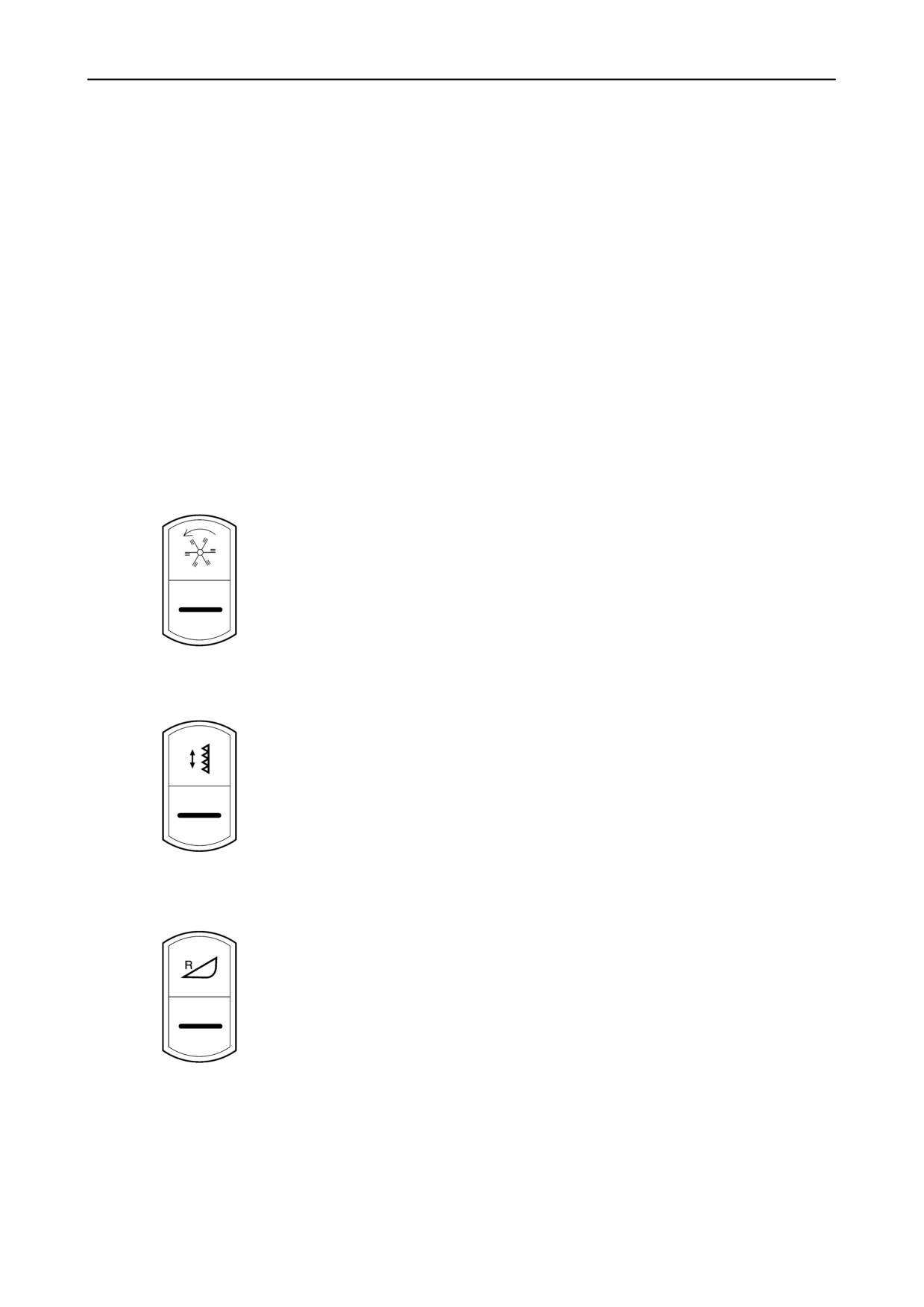
Vertical knives tumbler switch (if installed)
• Both vertical knives ON
• OFF
• Vertical right-hand knife ON
21.
Straw elevator reverse tumbler switch
Use this switch in combination with the reel speed increase (reversing) or
decrease (rocking) button on the multi function handle.
• ON
• OFF
2-10
SECTION 2 - CONTROLS, INSTRUMENTS AND OPERATION
22. Cup holder
23.
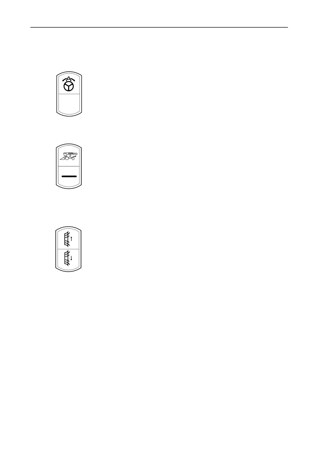
SmartSteert rocker switch (if installed)
• SmartSteert enable/disable/calibration
• Neutral
• Not used
24.
Automatic Crop Settings tumbler switch (ACS)
• Mode 2
• Mode 1
25.
Chopper spreader plates rocker switch (if installed)
• Towards right-hand side
• Neutral
• Towards left-hand side
26. Armrest
This armrest can be flipped-up to give access to a removable storage bin for small items.
27. Armrest
This armrest can be flipped-up to give access to the programmable settings keypad, and for use or cleaning the module
top.
2-11
SECTION 2 - CONTROLS, INSTRUMENTS AND OPERATION
Multi-Function Handle
12
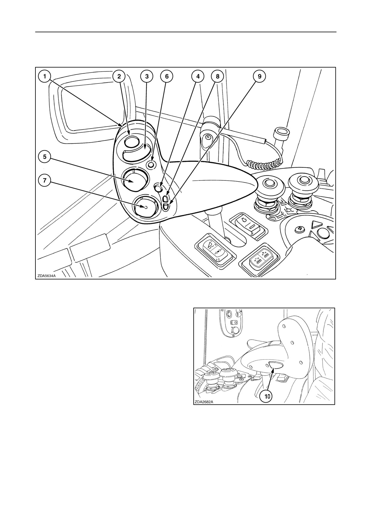
1. Multi-function handle (MFH)
With this handle the forward and reverse ground
speed of the combine can be controlled. Move the
MFH forward or backwards till it locks into neutral
position to stop the combine.
To drive the combine (forward or reverse), push
switch 10 on the back of the MFH to activate the
neutral unlock mechanism. The more the MFH is
moved forward or backwards, the faster the
combine will drive forward or reverse.
To warn other people, an audible alarm will sound
13
as long as the combine is in reverse driving mode.
2-12
SECTION 2 - CONTROLS, INSTRUMENTS AND OPERATION
4.
Automatic header height control button
WARNING
In case of an emergency stop it will not be enough to
move the multifunction handle to neutral, also apply
When this button is pressed and released:
the brakes.
• the attachment will automatically lower (or
raise) to a preset height (refer to paragraph
2.
Unloading system engagement button
headed ”Operation” further in this section).
Press on the button to start unloading, Press
• and when in headland mode (refer to ACS
again to stop.
operation), headland mode will be end and
Mode “1” or “2” will be reselected.
3.
Unloading tube swing rocker button
• and when using SmartSteert system, this
Left : unloading tube swing out (two positions)
will allow auto steering to activate also
depending on other conditions.
Right : unloading tube swing in (two positions)
When operating in an automatic mode, pressing
• Threshing mechanism NOT ENGAGED:
this button twice will:
(Field mode selected)
• lift the header above maximum stubble
Press the button (first or second position) and
height.
keep it depressed to swing the unloading tube out
or in.
• activate headland mode/ stop auto steering.
(If ACS / SmartSteert installed)
• Threshing mechanism ENGAGED:
(straw elevator maybe disengaged)
When operating in an automatic mode, pressing
this button for a minimum of two seconds will save
The first position:
the current head position and verify with a beep.
The unloading tube will open or close as long as
the button is depressed.
5.
Header height and header lateral floatation rocker
switch
Second position:
Giving one pulse on the button will swing the
With the upper and lower part of this switch, the
unloading tube completely out or in.
header can be moved up and down respectively.
Press again on either of the switches (left/right)
The header height switch offers two speeds.
to stop the automatic movement.
Pushing the switch to its first stop, both up and
down, the movement will be slow. When pushed
to the second stop, the up and down movement
NOTE: When the opposite part of the button is pulsed
will be fast. (according to the header raise/lower
in the second position, the unloading tube will move
speed)
in the opposite direction until it is completely open or
closed.
With the left and right part of the switch, the lateral
float of the header can be adjusted. Pushing to
the left will tilt the header counter-clockwise,
pushing to the right will tilt the header clockwise.
When using SmartSteert, pushing left or right
together with neutral unlock switch (1)
(see fig. 13):
• for minimum two seconds will select left/right
crop edge respectively.
(refer to SmartSteert operation).
• when pulsed, will adjust machine position to
left/right with +/- 10 cm.
2-13
SECTION 2 - CONTROLS, INSTRUMENTS AND OPERATION
6.
Quick stop button.
7. Reel position rocker switch.
One pulse on the red quick stop button will stop
With the upper and lower part of this switch, the
the straw elevator/header drive, and the
reel can be moved up and down respectively.
unloading auger drive immediately. Use this quick
stop to avoid crop blockage or combine damage.
With the left and right part of the switch, the reel
can be adjusted forwards and rearwards.
Also during opening or closing the grain tank
Pushing to the left will move the reel to the front,
extensions
(covers), this
action stops
pushing to the right will move the reel to the rear.
immediately when pushing on this button.
NOTE:
The emergency stop is also included on the quick
- In case a flip-up maize header is attached
stop button. (Only if installed in InfoViewt)
(selected): Pushing to the left will open the flip-up
maize header, pushing to the right will close the
• If pressing not longer than two seconds on
flip-up maize header.
- In case a Varifeedt grain header is attached
the quick stop button:
The hydrostatic will be disabled immediately.
(selected):
To move the knife bar forward: Press the neutral
unlock switch and simultaneously the reel position
• If pressing between two and six seconds on
rocker switch
(forward) to moves the knife bar
the quick stop button:
forward.
The hydrostatic will be disabled immediately.
To move the knife bar rearward: Press the neutral
After two seconds the parking brake will
unlock switch and simultaneously the reel position
come on additional, during four seconds.
rocker switch
(rearward) to moves the knife bar
rearwards.
• If pressing for a minimum of six seconds on
the quick stop button:
The same result will occur when pressing
between two and six seconds, but after six
8. Reel speed increase button.
seconds the parking brake will close
completely to stop the combine abruptly.
(Header and straw elevator reversing control, if
used in combination with the straw elevator
reversing tumbler switch).
NOTE: After an emergency stop, to advance again,
bring first the multi-function handle back to neutral
(the parking will be released automatically).
9. Reel speed decrease button.
(Header and straw elevator rocking control, if
used in combination with the straw elevator
reversing tumbler switch).
2-14
SECTION 2 - CONTROLS, INSTRUMENTS AND OPERATION
Shaft Speed Monitor (SSM)
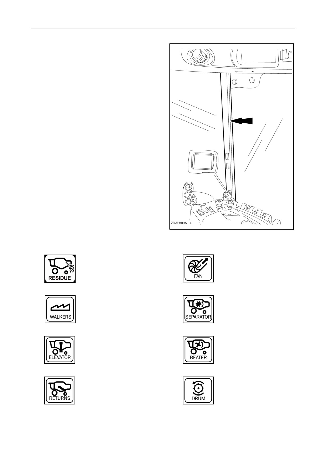
The Shaft Speed Monitor (SSM) (1) is located to the
front and to the right of the operator, integrated in the
cab frame.
The SSM features low speed warning alarms
accompanied by an audible alarm for several shaft
speeds.
When the ignition key is rotated to the ”contact”
position, the SSM shows a lamp test for a short time.
The SSM will continuously show fuel level and engine
coolant temperature on its two digital bar graphs.
These gauges also include alarm and warning lights.
NOTE: The backlighting of the SSM can be adjusted
via the InfoViewt monitor. Refer to
“VII Configurations and Calibrations”, paragraph;
“4.Display settings”, headed: “SSM lcd backlight”.
14
1.
Residue low speed warn-
5.
Cleaning fan low speed warning
ing light (if installed)
light
2.
6.
Straw walkers low speed warning
Rotary separator low speed warn-
light
ing light
3.
Grain elevator low speed warning
7.
Beater low speed warning light
light
4.
8.
Return(s) low speed warning light
Drum low speed warning light
2-15
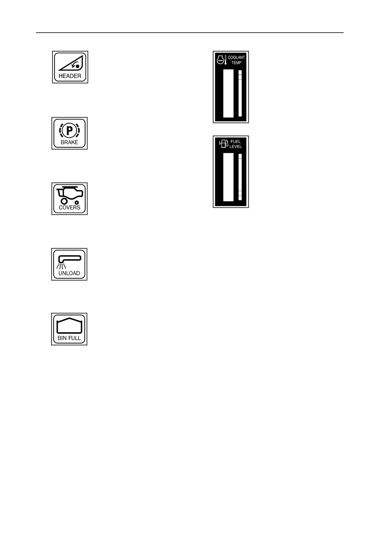
SECTION 2 - CONTROLS, INSTRUMENTS AND OPERATION
9.
14.
Not used
Coolant temperature
10.
Parking brake on
On: parking brake engaged
Blinking: when MFH is not in neu-
15.
Fuel level
tral with engine running and park
engage, brake pad worn
or brake fluid low
11.
Grain tank covers open
(if in-
stalled) when threshing not en-
gaged
12.
Unloading tube open
On: when unloading auger ex-
tended
Blinking: when unloading auger
is engaged
13.
Grain tank full
On: when grain tank is 75% full
Blinking: when grain tank is 100%
full
(Linked up with buzzer)
2-16
SECTION 2 - CONTROLS, INSTRUMENTS AND OPERATION
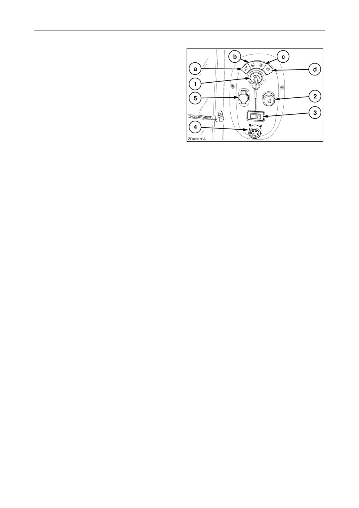
Start module
The start module is located to the right and to the back
of the operator’s seat.
1. The ignition key has three or four positions:
a Accessories (if installed)
b Off
c Contact
d Engine starter motor
2. Cigarette lighter
15
3. Indicator light for cold start preheater (if installed)
4. Diagnostics port for off-board diagnose and software
download.
5.
12 volts DC socket (only current with ignition key in
contact position)
NOTE: Do not leave the cab with the ignition key in
“accessories” position for a long time.
Mirror heating can decharge the batteries if the mirror
heating tumbler switch is in “on” position.
NOTE: When the ignition key is moved to the
“contact” position, the back-up alarm will be sound for
one second and the beacon lights (if equipped) will be
activated for 2.5 seconds.
2-17
SECTION 2 - CONTROLS, INSTRUMENTS AND OPERATION
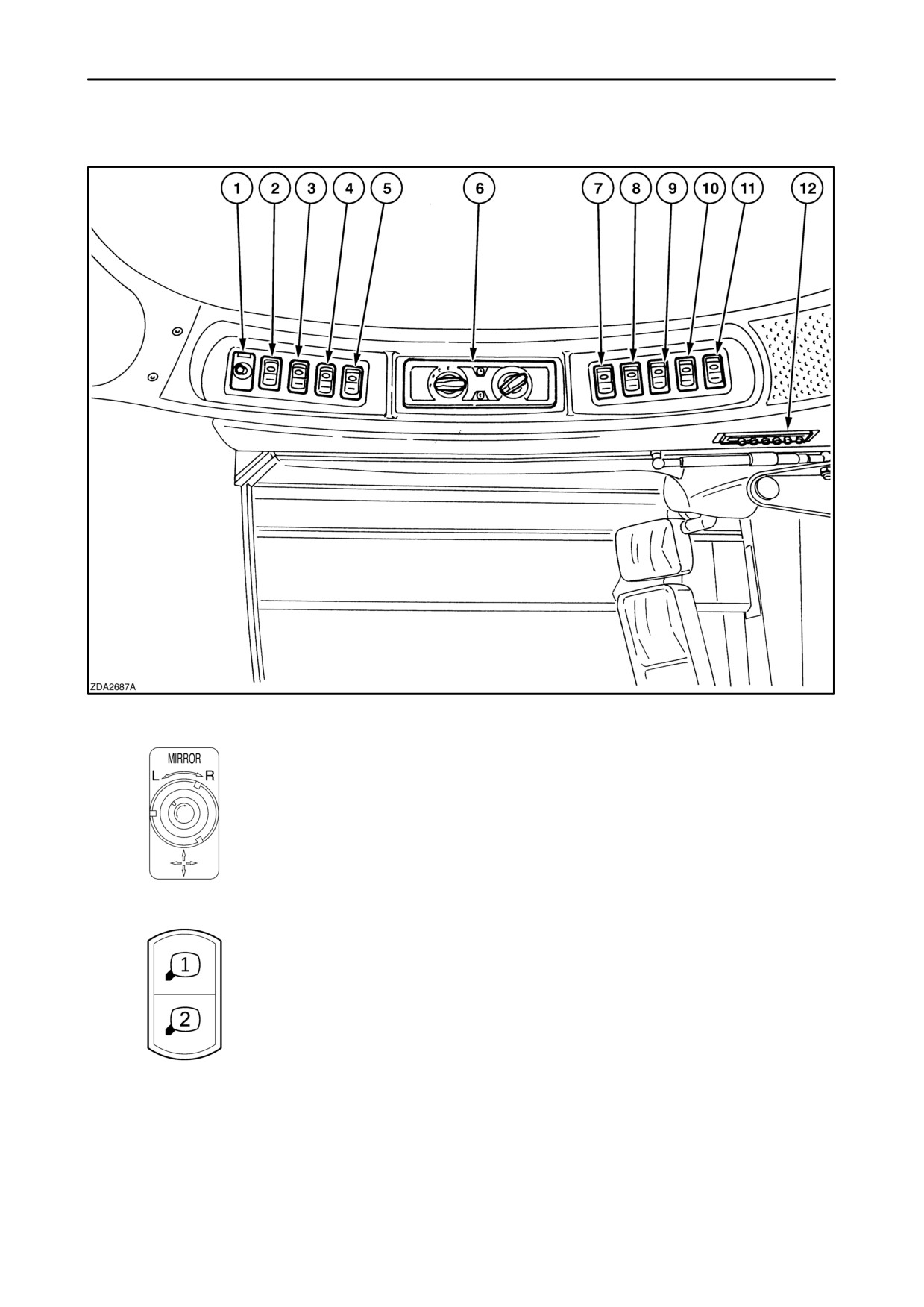
Cab roof controls
16
1.
Mirror adjustment switch
• Arrow to the left: left-hand mirror
• Arrow to the right: right-hand mirror
2.
Mirror select tumbler switch (if installed)
• Main mirror adjustment
• Additional mirror adjustment (Germany only)
2-18
SECTION 2 - CONTROLS, INSTRUMENTS AND OPERATION
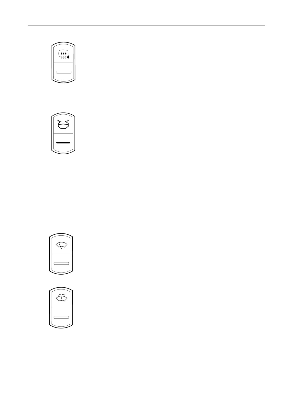
3.
Mirror heating tumbler switch
• ON
• OFF
4. Spare
5.
Grain tank covers open/ close tumbler switch(if installed)
• Open
• Closed
6. Climate control module (see further in this section)
• Manual controller
• Air conditioning and heating
• Air conditioning only
• Automatic Temperature Controller (ATC) (If installed)
7.
Windscreen wiper tumbler switch
• Wiper ON (continuous)
• Wiper ON (intermittent)
• Wiper OFF
8.
Windscreen washer rocker switch
• ON
• OFF
2-19
SECTION 2 - CONTROLS, INSTRUMENTS AND OPERATION
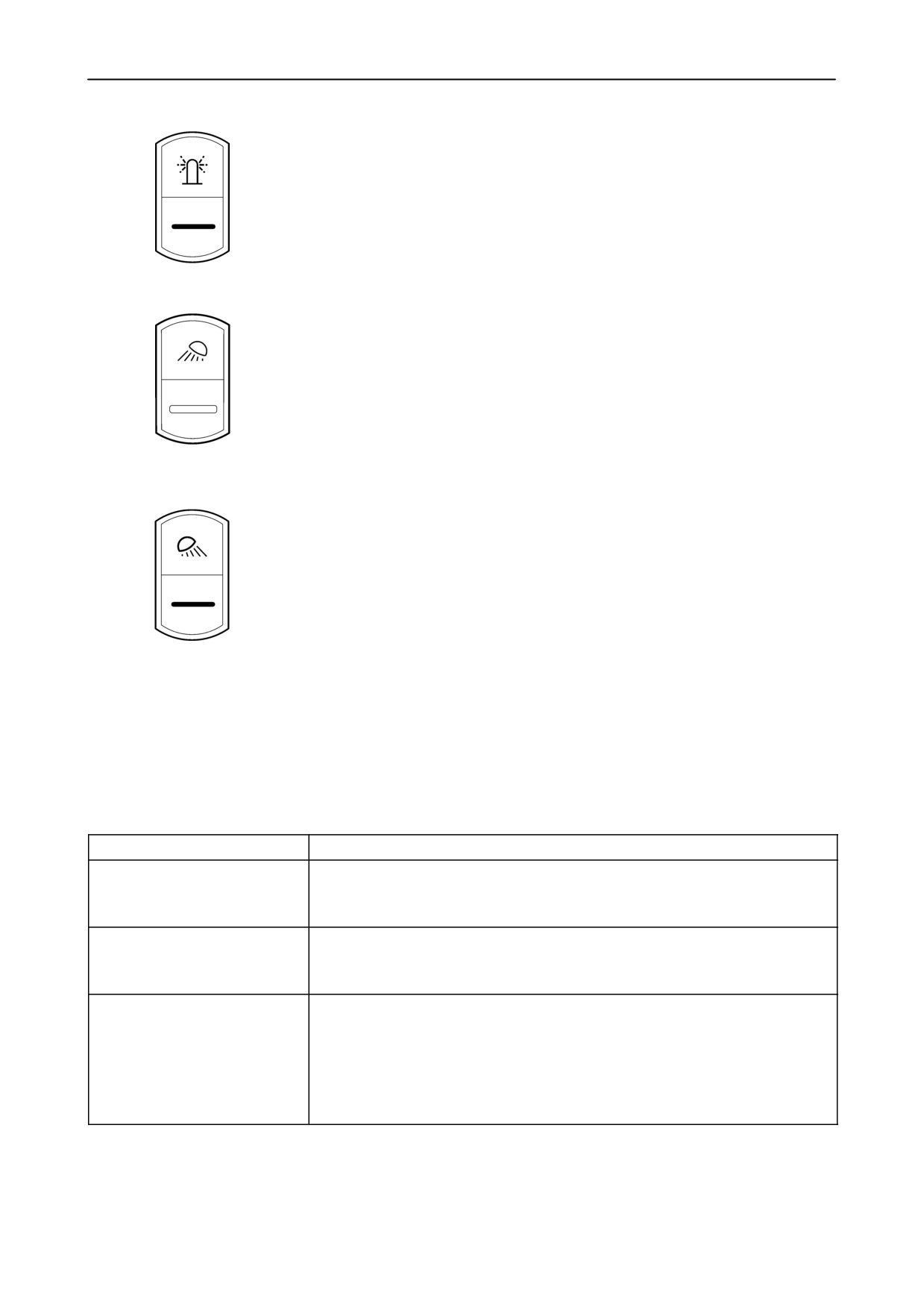
9.
Revolving flash lights tumbler switch
• ON
• OFF
10.
Rear operating lights tumbler switch (if field mode selected)
• ON
• OFF
11.
Front operating lights tumbler switch
• If field mode:ON (position 2): inner and outer cab roof lights+central operating light,
stubble lights, header lights
• If road mode:ON (position 2): inner and outer cab roof lights, parking lights
• If field mode:ON (position 1): outer cab roof lights+central operating light,
stubble lights, header lights
• If road mode:ON (position 1): outer cab roof lights, parking lights
• OFF
12. Adjustable air vent
Front operating lights tumbler switch summary:
(position 1 or 2)
(only with ignition key on)
Conditions
Unload tube light
- Field mode selected
- Front or rear operating lights ON
- By pressing unloading tube swing rocker button open (after 3 seconds)
Rear operating lights
- Field mode selected
(tumbler switch 10: OFF position)
- Front operating lights ON
- Reverse driving
Side operating lights
- Field mode selected
- Front operating lights ON
and
- Direction indicator (left or right)
or
- Header above maximum stubble height
2-20
SECTION 2 - CONTROLS, INSTRUMENTS AND OPERATION
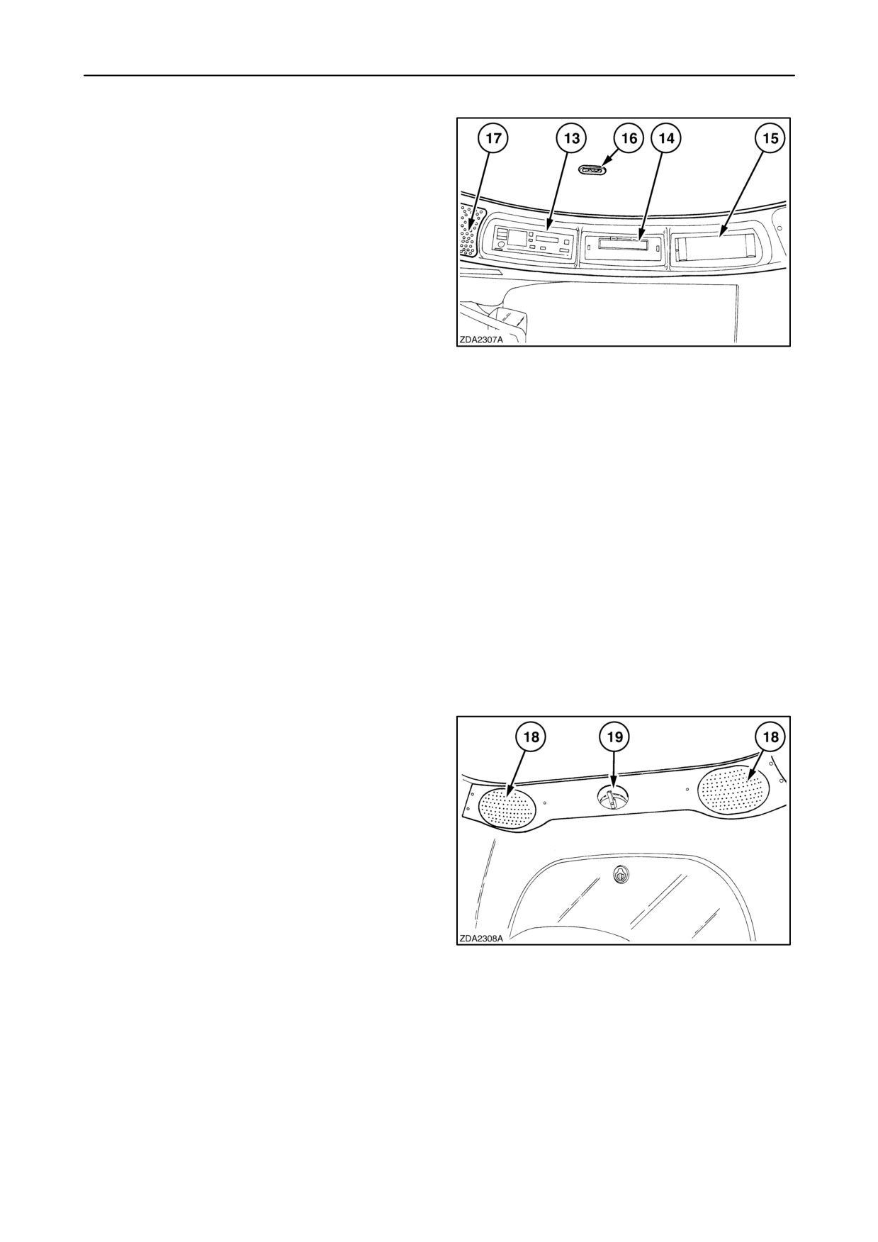
13. Radio location with
•
12 Volts DC connection
• Loudspeaker connection
• Antenna connection: AM / FM antenna
(cable pre installed)
14. Precision Farming data logger (if installed)
CAN network connection is foreseen
15. (D)GPS receiver (if installed)
17
CAN network connection is foreseen
IMPORTANT: Do not change the sequence of the
modules (Radio - Data logger - (D)GPS receiver)
16. Spotlight
This spotlight illuminates the right-hand module.
The spotlight operates together with the parking lights
and operating lights.
17. Loud speakers (front), (if installed)
2 speakers (mid and high range)
18. Loud speakers (rear)
2 speakers (low range)
19. Hook for clothes
18
2-21
SECTION 2 - CONTROLS, INSTRUMENTS AND OPERATION
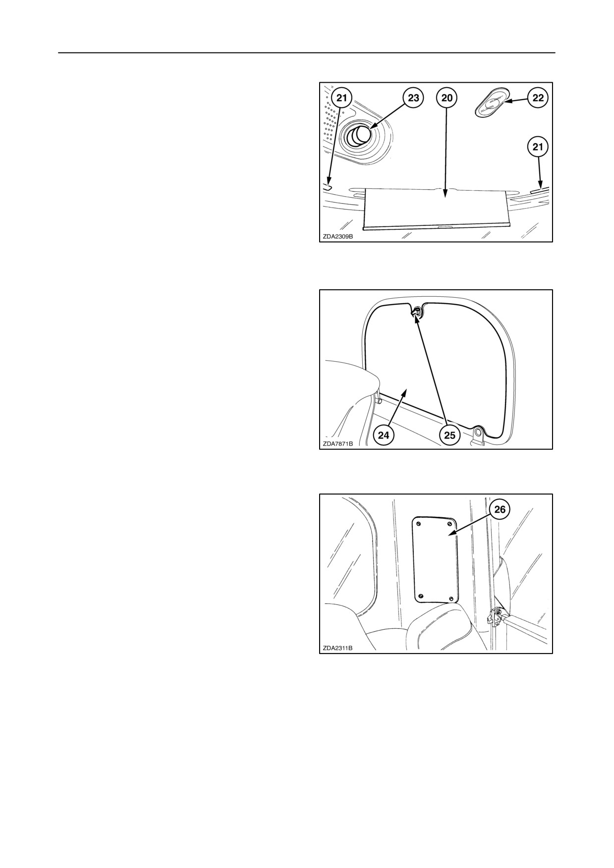
20.
Sunshade
21.
Adjustable air vents
22.
Cab interior light
There are three positions:
• OFF
• MIDDLE: The light illuminates when the cab door
is open. The light goes out +/- 30 seconds after the
cab door is closed and at the mean time the both
side lights starting illuminate for two minutes.
• ON
19
23.
Adjustable air vent
24.
Grain tank window
25.
Grain tank window latch
Open the grain tank window by turning the knob to
clean the area between the grain tank and the cab.
20
26. Fuse and relay panel cover
To open, turn the black buttons to a vertical position.
To lock, turn the buttons to a horizontal position.
In the back left corner of the cab, behind this cover is the
fuse and relay panel.
Install panel layout picture from this manual in the
plastic pocket on the backside of this cover.
21
2-22
SECTION 2 - CONTROLS, INSTRUMENTS AND OPERATION
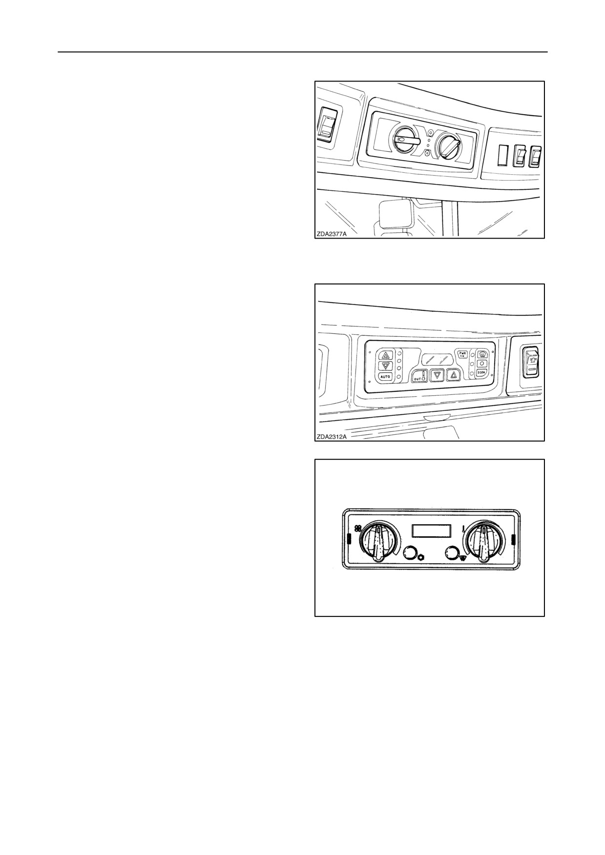
Climate control
The panel is located in the headliner at the left side
above the operator’s seat.
There are two types of control panels:
1. Control panel of the manual controller.
There are two types:
• Air conditioning and heating
22
• Air conditioning only
2. Control panel of the Automatic Temperature
Control (ATC). (If installed)
Type I
23
Type II
50030142
24
2-23
SECTION 2 - CONTROLS, INSTRUMENTS AND OPERATION
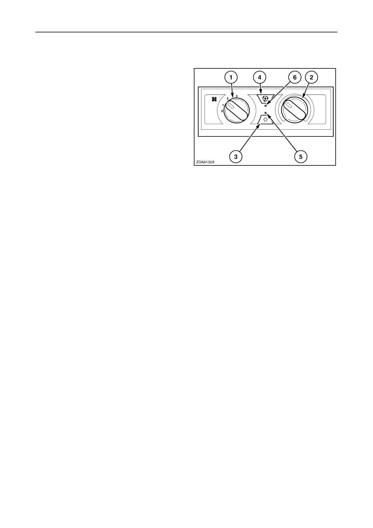
1. MANUAL CONTROLLER
Fan switch (1):
• The switch has four positions:
0: OFF
1: Low fan speed
2: Medium fan speed
3: High fan speed
• The knob is rotated in the clockwise direction to
increase the blower speed and rotated in the
counter clockwise direction to decrease the
blower speed.
25
• In the OFF position the fresh air dust separator
blower will also be turned off.
Temperature control (2):
• The system will be at maximum cooling when the
knob is rotated the maximum amount in the
counter clockwise direction.
• The system will be at maximum heating when the
knob is rotated the maximum amount in the
clockwise direction.
A/C switch (3):
• This switch turns the air conditioner either on or
off. (indicated by led 5)
Recirculation switch (4):
• For maximum cooling or heating depressing this
button will turn off the fresh air dust separator
blower. (indicated by led 6)
NOTE: Do not leave in this position for more than 15
minutes for best filtration efficiency.
2-24
SECTION 2 - CONTROLS, INSTRUMENTS AND OPERATION
2. AUTOMATIC TEMPERATURE CONTROL (ATC)
Type I
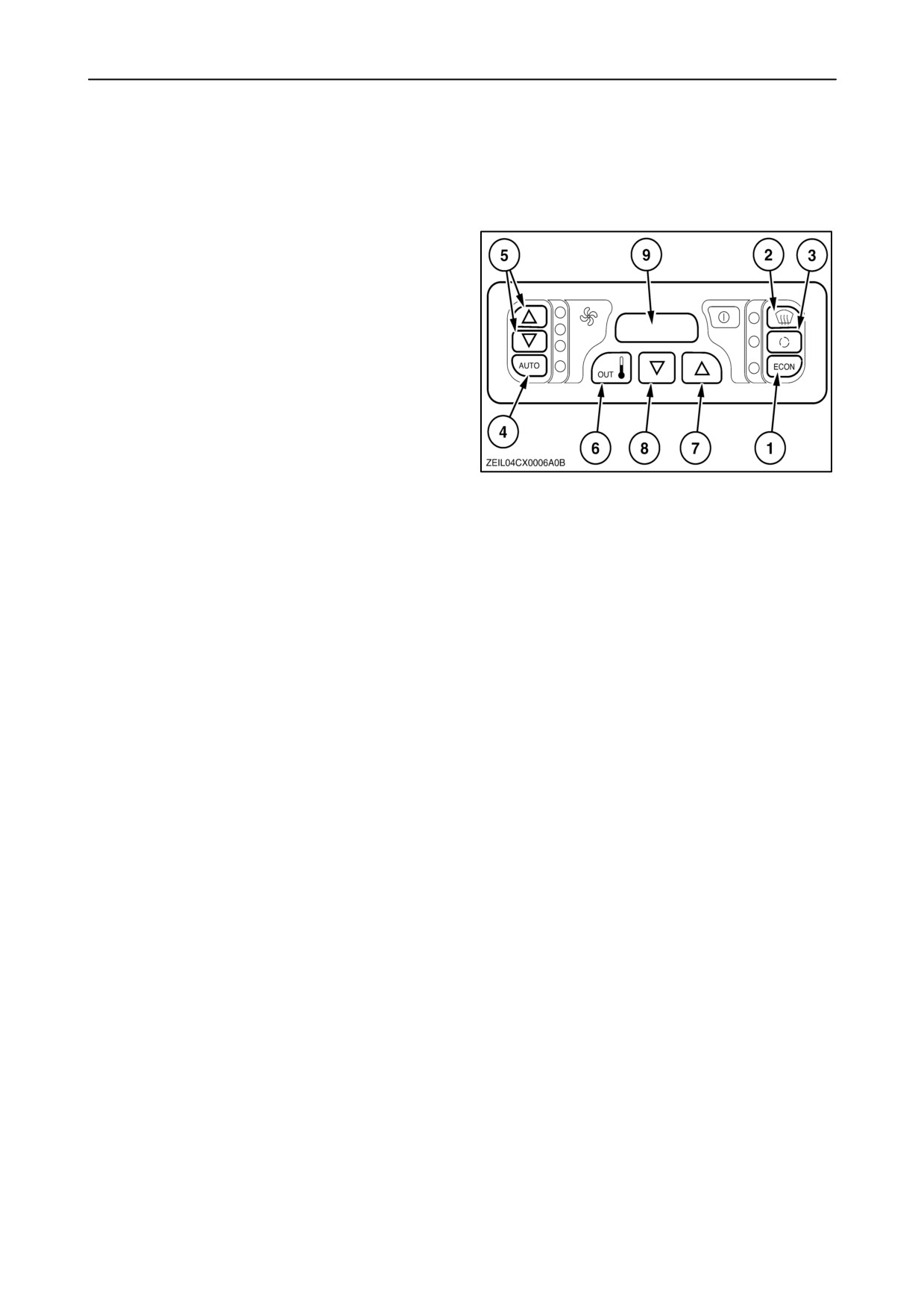
Mode control:
The operating mode selections will be ”Automatic”,
”Defog”,
”Recycle” and
”Econ” or economy.
Operating mode is selected by pushing the button
switches (1) - (4).
• Economy (1):
When you press the ”Econ” button (1) you only have
the circulation of fresh air by a fan speed that is
manually set (see further).
The A/C and the heater are turned off.
26
• Defog (2):
In ”Defog” mode, the compressor is on unless turned
off by the freeze sensor or by the pressure switches.
Water valve position is automatic.
• Recycle (3):
If recirculation mode is selected, the fresh air dust
separator blower is turned off for 15 minutes. This will
provide the fastest cooling or heating of the cab.
• Automatic (4):
If the module is not in ”Econ” or ”Defog” mode, it is in
automatic mode. Water valve position and
compressor operation is automatic.
Fan speed selection:
The fan speed can either automatic or manually set
by the operator. When the manual mode is selected
by pressing the button (1), three fan speeds can be
selected: low, medium and high. Change the fan
speed by pressing button (5).
If the automatic mode is selected, the fan speed will
automatically be adjusted to obtain the desired cab
temperature.
2-25
SECTION 2 - CONTROLS, INSTRUMENTS AND OPERATION
Cab temperature selection:
The desired cab temperature setpoint can be
changed by pressing buttons (7) or (8).
Button (7) to increase and button (8) to decrease the
set point. Pushing button (7) or (8) will cause the
display to show the desired temperature setpoint, but
not the actual cab temperature.
If the fan speed is in auto mode, then the fan speed
will also be adjusted to achieve or maintain the
desired cab temperature setpoint.
• Outside temperature display:
The outside temperature will be displayed for 5
seconds by pressing the button (6).
• Temperature display format
Pressing the buttons (6) and (7) simultaneously will
cause the display to switch between Celsius and
Fahrenheit.
Remark: If an error occurs the number of the error
code will appear on the display (9). The description of
the error can be find in the error table. Contact your
local New Holland dealer if there is a problem.
2-26

SECTION 2 - CONTROLS, INSTRUMENTS AND OPERATION
Error table
Error
Possible cause
00E
Indicates end of diagnostic sweep
10E
Cab sensor open
11E
Cab sensor shorted
12E
Cab sensor out of range high
13E
Cab sensor out of range low
20E
Outlet sensor open
21E
Outlet sensor shorted
22E
Outlet sensor out of range high
23E
Outlet sensor out of range low
30E
Ambient sensor open
31E
Ambient sensor shorted
32E
Ambient sensor out of range high
33E
Ambient sensor out of range low
40E
Evaporator sensor open
41E
Evaporator sensor shorted
42E
Evaporator sensor out of range high
43E
Evaporator sensor out of range low
60E
Low pressure sensor open
61E
Low pressure sensor shorted
62E
Low pressure sensor fault ”STATIC”
63E
Low pressure sensor fault “LATCH OUT”
70E
High pressure sensor open
71E
High pressure sensor shorted
72E
High pressure sensor fault ”STATIC”
73E
High pressure sensor fault “LATCH OUT”
80E
Driver fault “CLUTCH OVER CURRENT”
81E
Driver fault “OPEN CLUTCH”
82E
Driver fault “ACTUATOR OVER CURRENT”
83E
Driver fault “BLOWER OVER CURRENT”
90E
Memory fault “WRITE ERROR”
91E
Memory fault “READ ERROR”
2-27
SECTION 2 - CONTROLS, INSTRUMENTS AND OPERATION
Type II
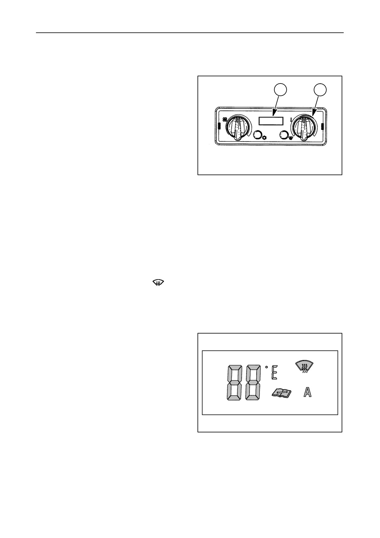
Temperature control (1)
2
1
The temperature control gives the operator control
over the cab interior temperature. Turning the control
clockwise will increase the temperature of the air and
turning the control counter-clockwise will lower the
temperature of the air.
Display unit (2)
The display provides the operator with information
about the systems performance.
50030142
•
It provides the desired cab temperature reading
selected by the operator. The display reading
27
may be in Fahrenheit or Celsius. To make the
changed between reading there is a ground wire
located under the left rear corner of the cab at the
main ground boss. Attaching the wire to the
ground provides for Celsius readings.
•
It illuminates an icon “A”, when the system is
operating in the automatic climate mode.
•
When the “A” is not illuminated the blower motor
speed MUST be manually controlled and “Auto”
mode will only control the water valve and
compressor, while trying to maintain the set
temperature.
•
It illuminates an icon of a windshield
when
the system is in the Defog mode.
•
It illuminates an icon of a book when the system
is not operating correctly. Along with the book
icon a fault code will also be displayed to assist
the technician making the correct repairs.
The range for ATC is from a setpoint of 16°C
(61°F) to 30°C (89°F). The setpoint of 16°C
(60°F) or 32°C (90°F) will be displayed and the
“A” icon on the display will be off when the system
is in maximum mode.
20030143
28
2-28
SECTION 2 - CONTROLS, INSTRUMENTS AND OPERATION
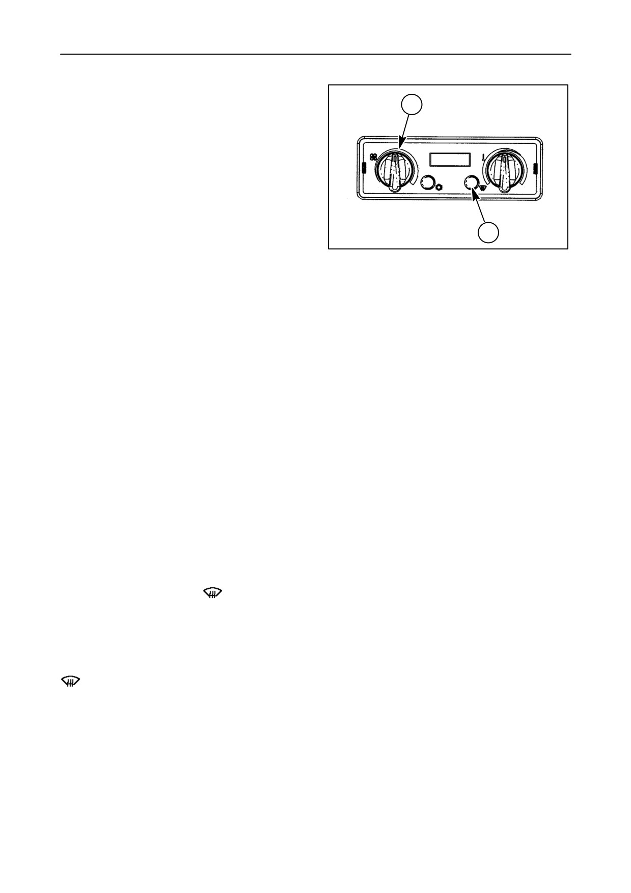
Blower speed control (3)
3
The blower speed control gives the operator control
over the speed of the blower motor. Turning the
blower control clockwise will increase the speed of
the blower, producing more airflow out of the cab
vents, turning the control counter clockwise will
reduce the air flow.
If the ATC control button has been pressed, the
blower speed control position will have NO effect over
the blower’s speed. The ATC controller will increase
4
or decrease the blower motor speed as needed to
50030142
maintain the desired cab temperature. If the blower
29
motor control is adjusted, the controller will release
the automatic control over the blower motor speed.
The blower motor will only operate in the manual
mode if the “A” is NOT displayed. The ATC control
button must be toggled OFF and back ON to reset the
automatic blower motor operating mode. The
automatic temperature control will always be
operating whether the “A” is displayed or not. The
blower control is a potentiometer rated at 10K 10%
ohms.
When operating in the auto climate or Defog mode,
the blower will make a speed increase for every (2°F)
difference there is between the temperature set point
and the actual cab temperature sensed by the cab
temperature sensor.
If the evaporator sensor senses that the evaporator
temperature is below 26°C (80°F), and system is
calling for heat the blower speed will not be increased
until the evaporator temperature has increase.
Mode control (4)
Once the operator has activated the ATC control, the
mode button is pressed to toggle between AUTO and
DEFOG. The digital display window will be
illuminated with the symbol
displayed. The
button toggles between two modes:
“A” = Auto, the system will warm or cool the air as
needed to maintain the cab temp and the display will
be illuminated.
= Defog, the system will run the A/C compressor
full time and warm the air to defog the windows and
the display will be illuminated.
2-29
SECTION 2 - CONTROLS, INSTRUMENTS AND OPERATION
ATC control (5)
The operator selects ATC control by pressing the left
hand button one time, the digital display window will
be illuminated. When illuminated the mode of
operation will be displayed along with the desired
temperature. The button toggles between two
modes:
•
“O” = OFF, the cab blower motor may be run, but
the air will not be conditioned and the display will
NOT be illuminated.
•
“A” = Auto, the system will warm or cool the air as
needed to maintain the cab temp and the display
5
will be illuminated.
50030142
30
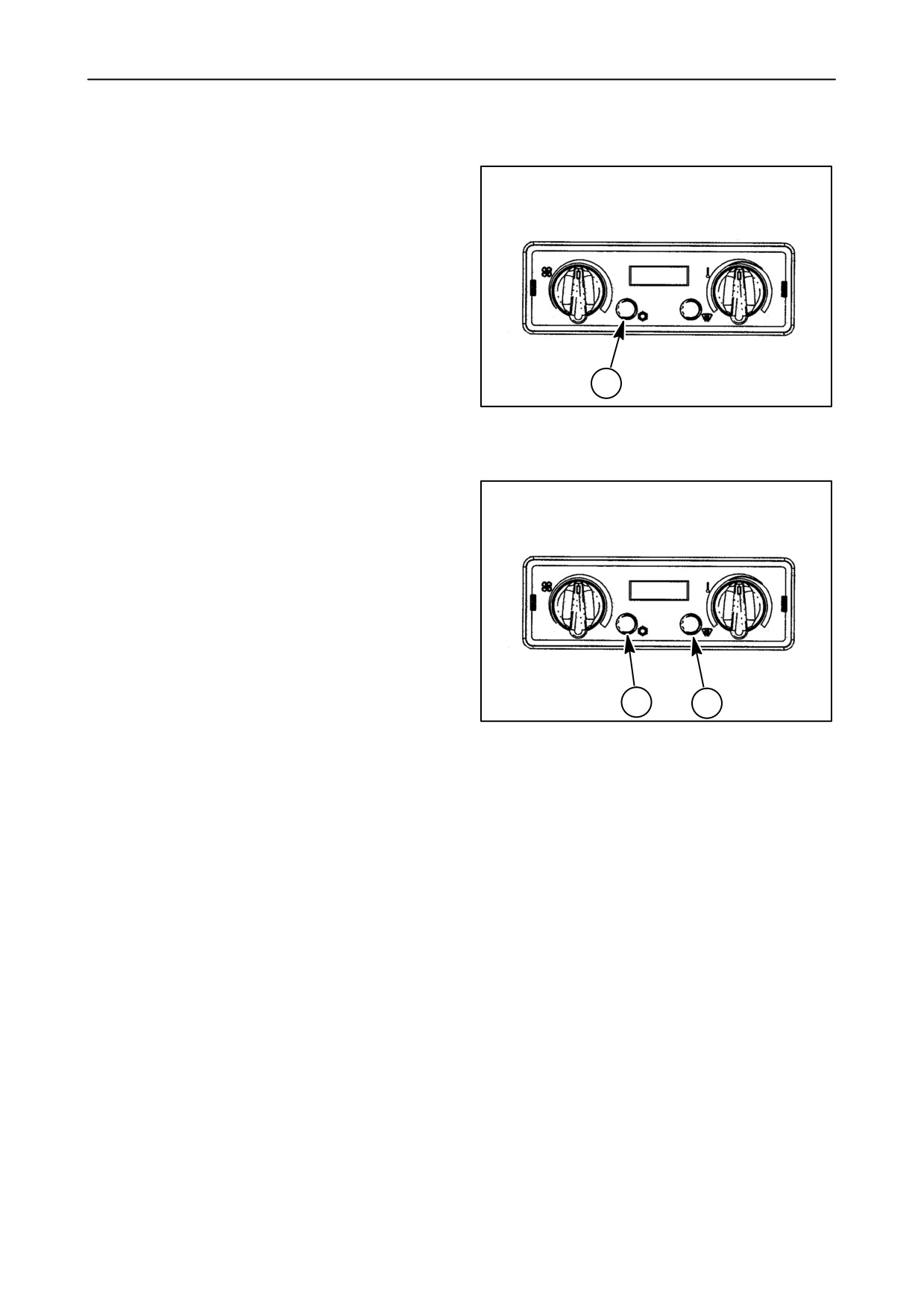
Defog control operation
Defog is used to clear off the windows by using the
A/C to lower the humidity in the air and using the
heater to warm the air enough to dry the windows.
The ATC control button (1) must be pressed to
activate the AUTO controls and the mode button (2)
toggled to DEFOG and the windshield icon will be
displayed in the digital display. The temperature
control knob may be adjusted to any setting. If the
cab vent temperature is too cold the temperature
control may be rotated clockwise to provide some
additional heating of the air. The cab temperature will
be monitored by the re-circulation air sensor, and be
maintained at the temperature control setting by
1
2
50030142
cycling the heater valve. While operating in the defog
31
operation the compressor will run continuously,
unless the evaporator sensor determines the
evaporator is too cold and could start to freeze up.
The ATC controller will automatically control the
blower motor speed as required to maintain the
temperature desired. It will be normal for the vent
temperature to be cold during early morning start up,
due to low engine temperature. If the operator
reduces the blower speed until the engine warms up,
the ATC controller will disengage the auto mode of
the blower speed. To re-activate the auto mode for
the blower motor speed, the ATC control button
MUST be toggled to reactivate the auto position.
2-30
SECTION 2 - CONTROLS, INSTRUMENTS AND OPERATION
Troubleshooting the temperature control
system
Code “01” displayed instead of temperature setting -
Code “08” alternating with temperature setting -
High pressure lockout, press the climate control
possible faulty cab temperature sensor or cab
switch (6) to the center OFF position, then to the
temperature is below
-19° C
(-2° F). Adjust
forward automatic position or rearward to the defog
temperature control above 23° C (74° F). If error code
position as required. Digital temperature display
does not clear after cab temperature rises above
should reappear. If code “01” reappears, system
-19° C (-2° F), system requires service. In order to
requires service.
continue operation, temperature control must be set
above 21° C (70° F) or below 19° C (66° F).
Code “02” displayed instead of temperature setting -
Low pressure lockout, press the climate control
Code “10” alternating with temperature setting -
switch to the OFF position, then to the automatic
possible faulty evaporator sensor or cab temperature
position. Digital temperature display will reappear. If
is below -19° C (- 2° F). Compressor does not run.
code “02” reappears, system requires service.
If error code does not clear after cab temperature
rises above - 19° C (-2° F), system requires service.
Code “04” alternating with temperature setting -
possible faulty blower control potentiometer, blower
Code “11” alternating with temperature setting -
defaults to maximum speed. System requires
possible faulty evaporator sensor or core tempera-
service.
ture has exceeded 82° C (180° F). Compressor does
not run. If error code does not clear, system requires
Code “05” alternating with temperature setting -
service.
possible faulty temperature control potentiometer,
system defaults to 20° C (68° F). System requires
service.
2-31
SECTION 2 - CONTROLS, INSTRUMENTS AND OPERATION
Lighting and Mirrors
32
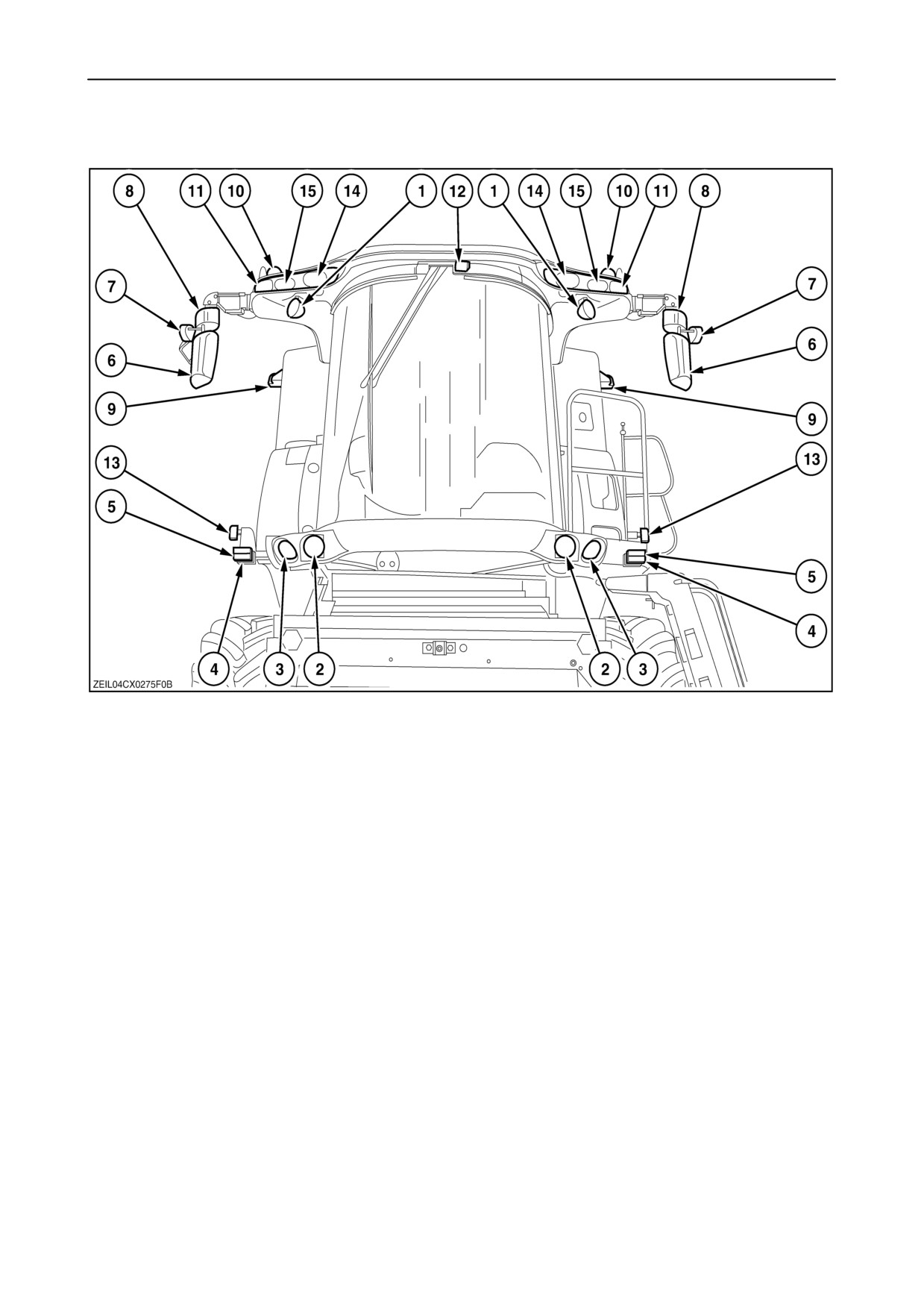
1. Header lights
2. Dimmed lights and headlights
3. Stubble lights
4. Parking lights
5. Direction indicator
6. Main electrically adjustable and heated mirrors
7. Side operating lights
8. Manually adjustable wide angle mirror (if installed)
9. Rear operating lights (not working in road mode)
10. Revolving flash lights (if installed)
11. Outer work lights
12. Central operating light
13. Side lights
14. Inner work lights
15. Middle work lights
2-32
SECTION 2 - CONTROLS, INSTRUMENTS AND OPERATION
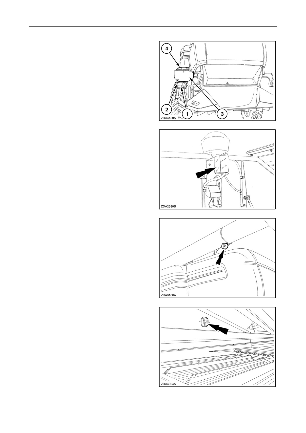
• Rear road lights 1
• Direction indicator 2
• Licence plate 3
• Licence plate lights 4
33
• Grain tank light
34
• Unload tube light
35
• Cleaning shoe light
36
2-33
SECTION 2 - CONTROLS, INSTRUMENTS AND OPERATION
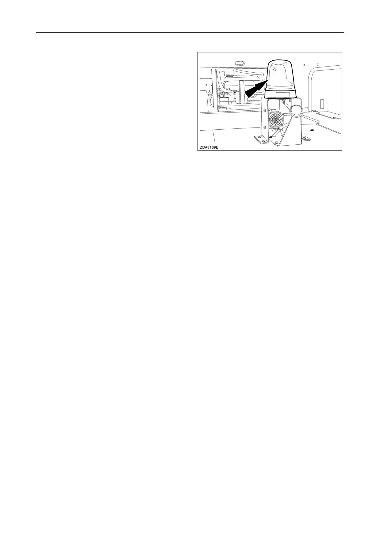
• Revolving flash light (if installed)
37
2-34
SECTION 2 - CONTROLS, INSTRUMENTS AND OPERATION
OTHER COMPONENTS
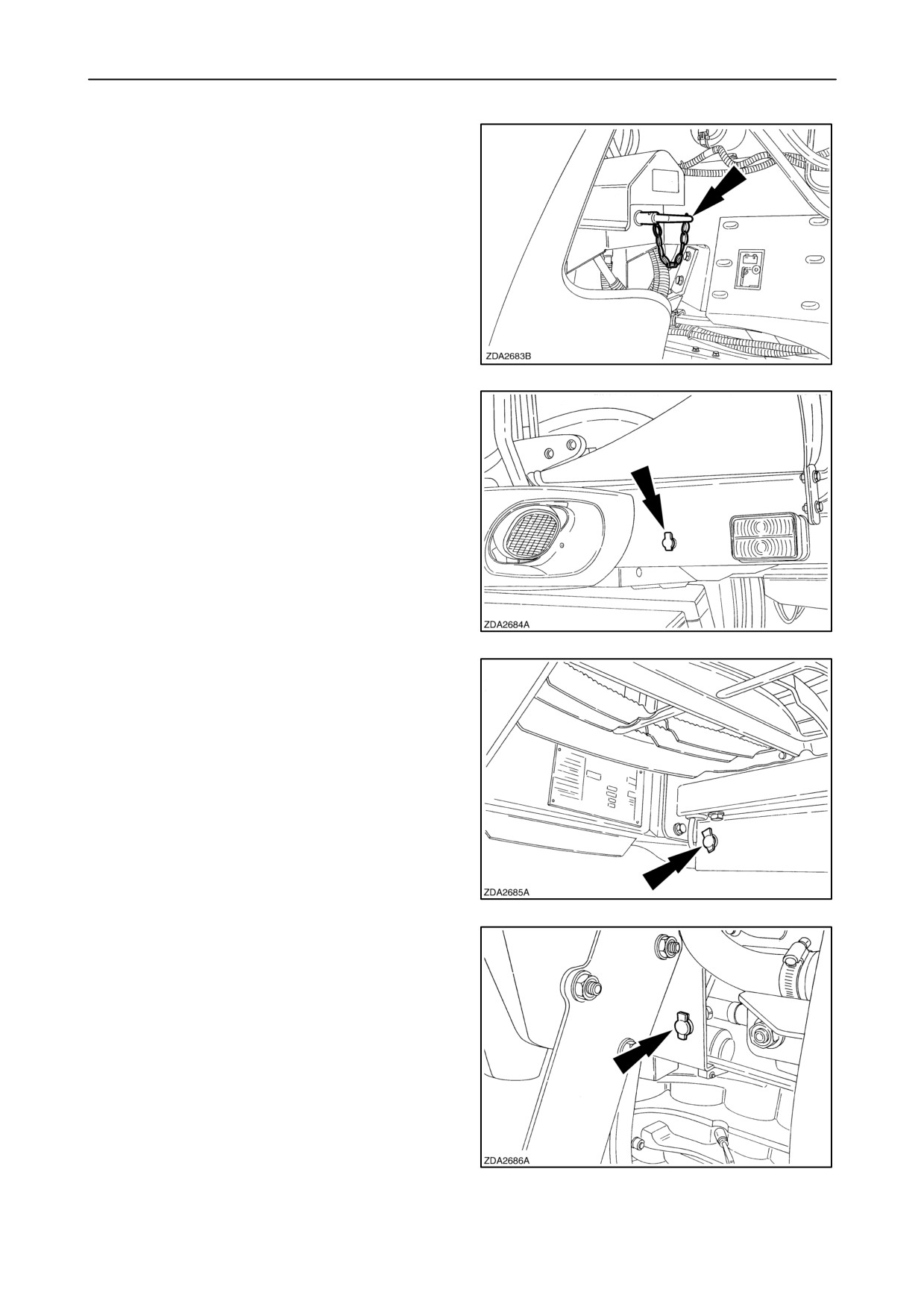
• Battery key
Turn the key counter-clockwise (1/4 turn) after having
switched off the ignition key.
Turn the key clockwise (1/4 turn) before switching on
the ignition key in the cab.
38
•
12-Volt DC socket (left)
Live at all times when the battery key is on.
39
•
12-Volt DC socket (right) (if installed)
Live at all times when the battery key is on.
40
•
12-Volt DC socket (engine compartment)
Live at all times when the battery key is on.
41
2-35
SECTION 2 - CONTROLS, INSTRUMENTS AND OPERATION
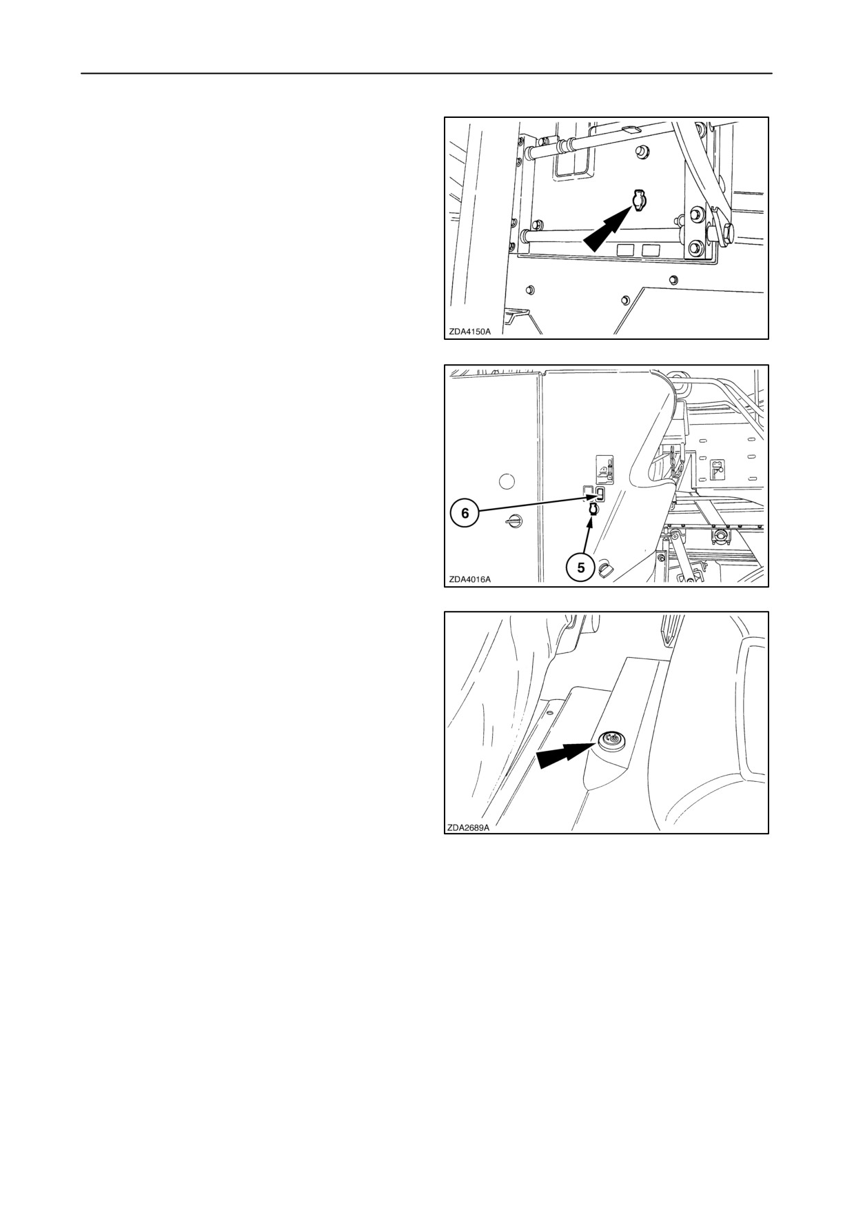
•
12-Volt DC socket located at the rear ladder.
Live at all times when the battery key is on.
42
•
12-Volt DC socket
5
(left-hand side rear
shielding) (if installed)
• Cleaning shoe light tumbler switch 6.
Live at all times when the battery key is on.
43
• Mobile phone plug (12 Volt DC socket), located
between the operator’s seat and the instructional
seat. (if installed)
44
2-36
SECTION 2 - CONTROLS, INSTRUMENTS AND OPERATION
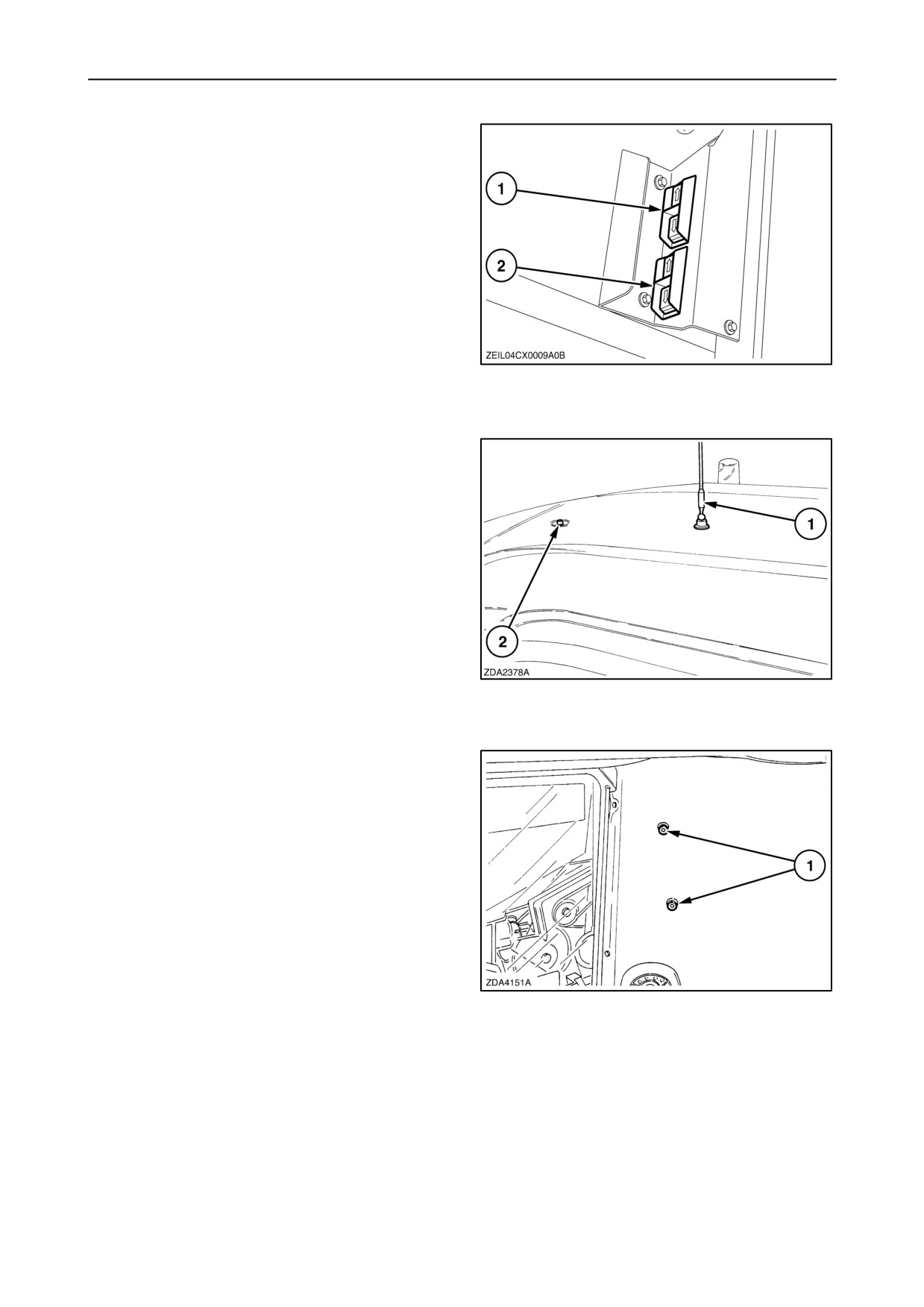
• Two rocker switches 1 and 2 are located at the
inside of the straw hood (left-hand side) to adjust
the electrically controlled lower and upper sieve.
(if installed)
45
• Radio antenna 1 (AM/FM)
• CB antenna 2 or Business Band antenna
(if installed)
46
• Two extra bolts 1 are provided (above the start
module) to install extra Communication / radio
equipment mounting.
47
2-37
SECTION 2 - CONTROLS, INSTRUMENTS AND OPERATION
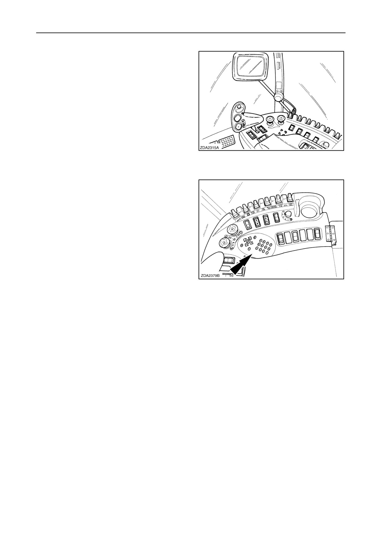
InfoViewt Monitor
The InfoViewt monitor is located on a movable arm
in front and to the right in the cab.
A grip/locking mechanism will keep the InfoViewt
exactly in place where you want it for optimal viewing
comfort.
This display is used to control all parameters and
settings of the combine. The display will also inform
the operator continuously about the combining
process and possible warnings or alarms.
48
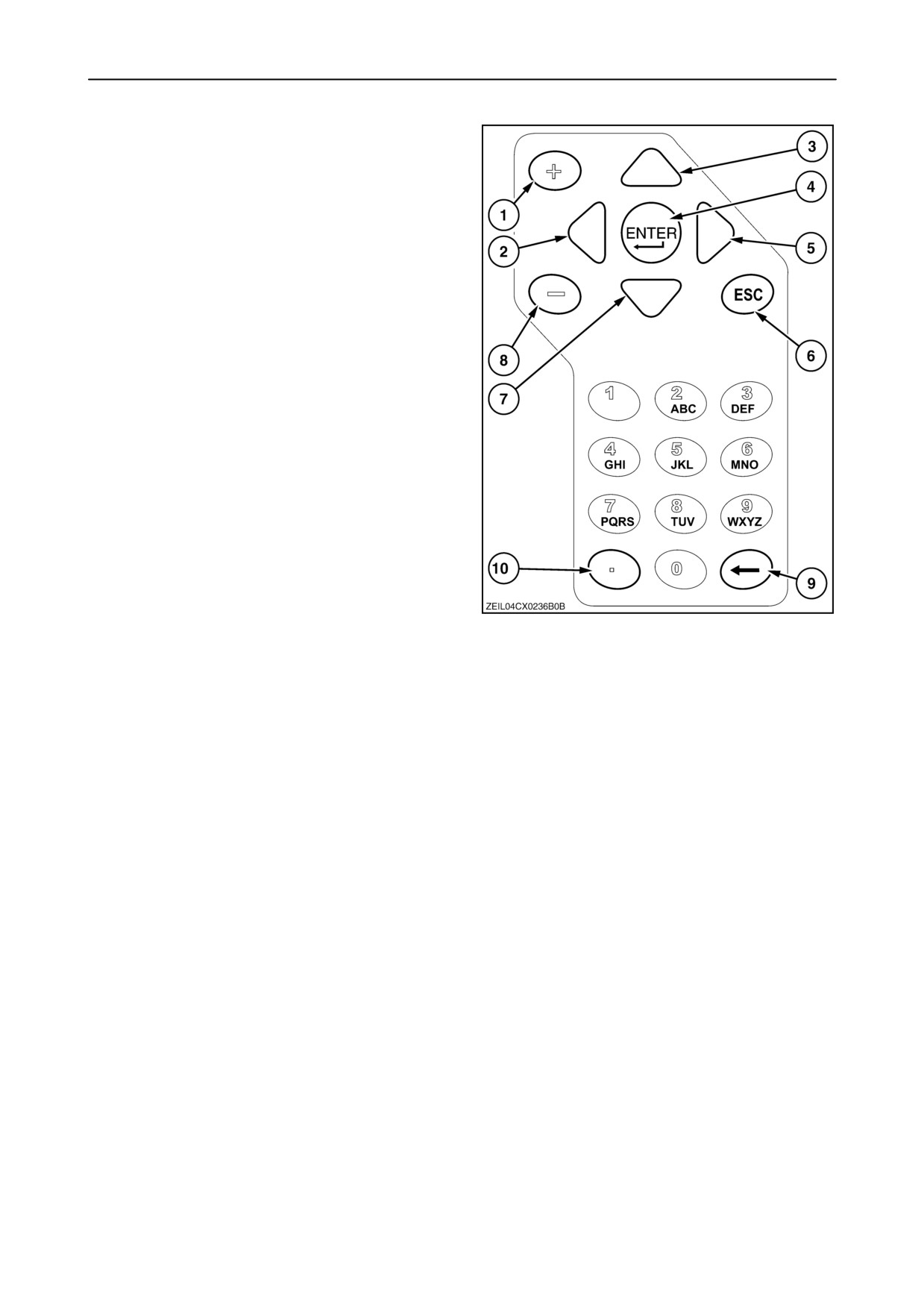
The InfoViewt is controlled with the cursor keys and
alphanumeric keypad on the right-hand module.
49
2-38
SECTION 2 - CONTROLS, INSTRUMENTS AND OPERATION
Explanation of the cursor keys and alphanumeric
keypad.
1. Plus key to change a set value
2. Menu navigation key (left)
3. Menu navigation key (up)
4. Enter key
5. Menu navigation key (right)
6. Escape key
7. Menu navigation key (down)
8. Minus key to change a set value
9. Back space key
10. Decimal separator / Print button
(if printer accessory installed)
Use the menu navigation keys (2), (3), (5) and (7) to
run through the different menus.
Using the Escape key (6) will shift the screen back to
the previous menu.
Use the plus or minus key (1) or (8) to change a value
or selecting another setting.
50
Press the enter key (4) to confirm any change or to
activate a function.
When the optional printer is installed, press the button
(10) to print a selected page on the InfoViewt.
2-39
SECTION 2 - CONTROLS, INSTRUMENTS AND OPERATION
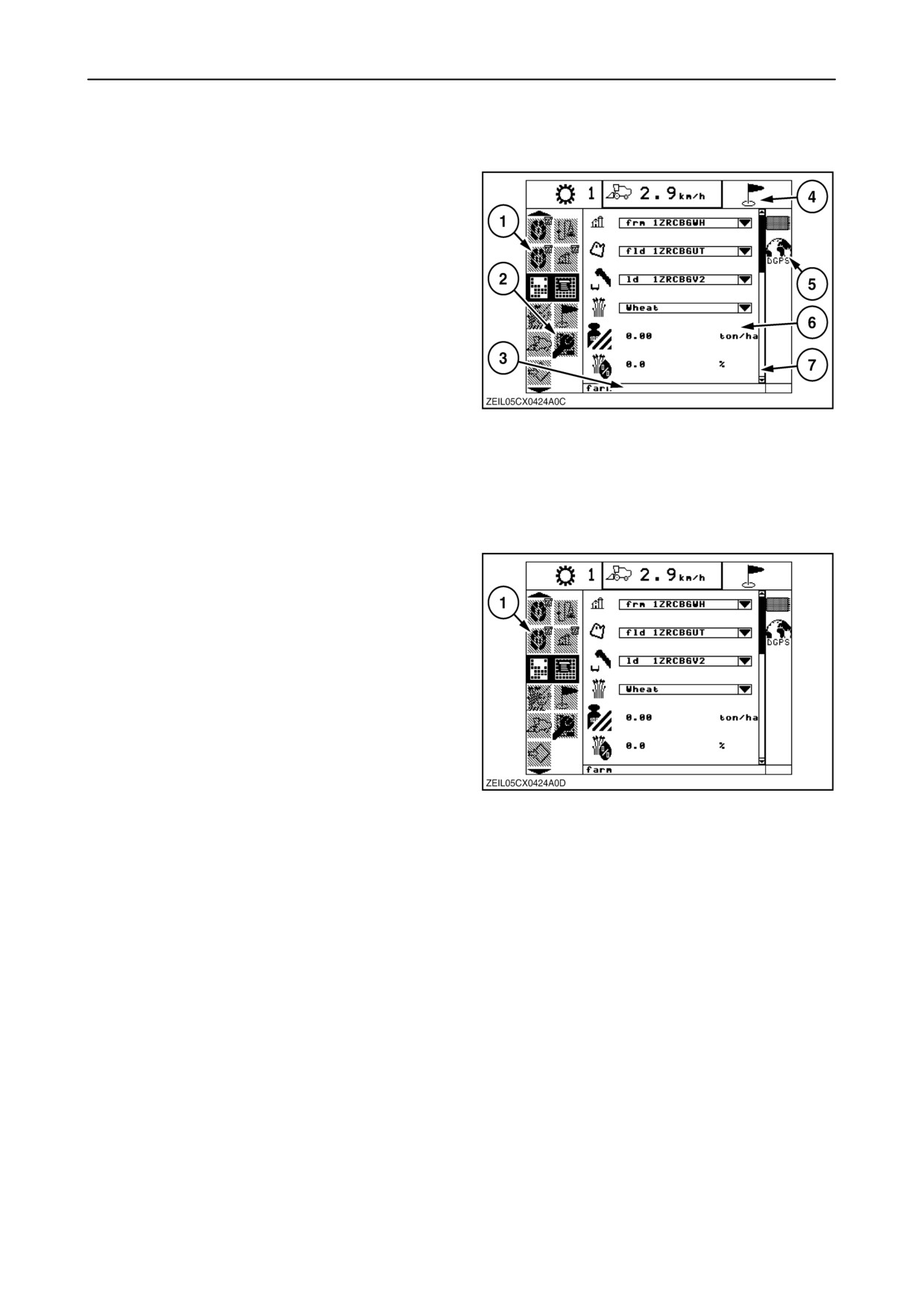
INFOVIEWt MONITOR
The monitor will switch on when the ignition key is
switched on.
The display is divided in different fields:
1. Menu bar
2. Sub-menu bar
3. Text bar
4. Indicator bar
5. Status bar
6. Information box
51
7. Scroll bar
1. MENU BAR
The menu bar 1 at the left side of the display shows
the different menus presented by a symbol. Text bar
3 (fig.
51) at the bottom of the screen, shows a
description of the selected menu.
Scrolling through the menu is possible by using the up
and down navigation keys:
The “up” key to select a menu up the ladder.
The “down” key to select a menu down the ladder.
52
Keeping the
“up” and
“down” navigation key
depressed will shift the menu quickly up or down.
The selected symbol always remains in the middle of
the menu bar and blinks to show the selected
position. When the navigation keys are not used for
a while, the selected symbol will stop blinking and will
be inverted until the navigation keys are used again.
2-40
SECTION 2 - CONTROLS, INSTRUMENTS AND OPERATION
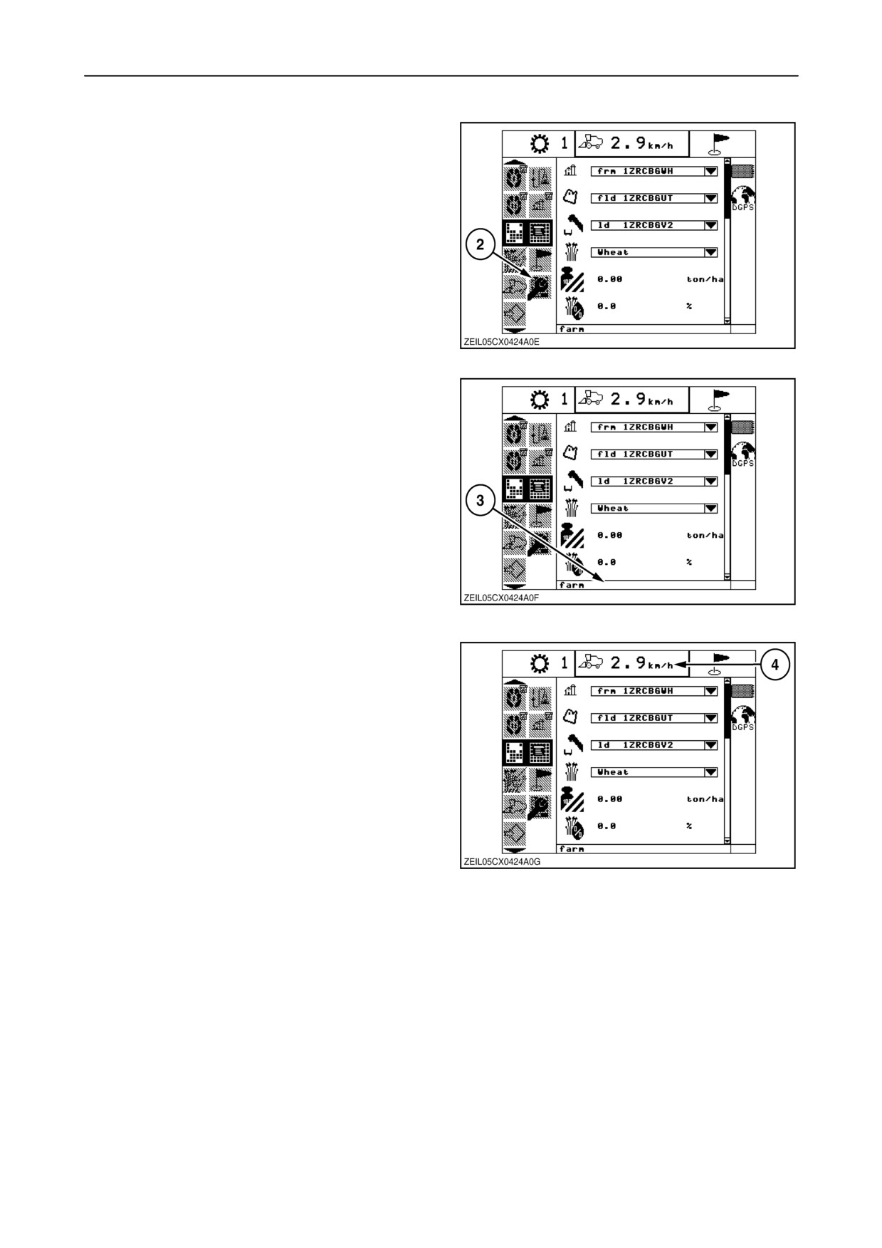
2. SUB-MENU BAR
With certain menus, a sub-menu bar 2 will appear. To
enter that sub-menu presses the ”right” navigation
key. Text bar 3 (fig. 54) will show a description of the
selected sub-menu.
NOTE: To move back into the main menu press the
”left” navigation key or press the ”esc” key.
53
3. TEXT BAR
At the bottom of the screen, text bar 3 displays a
description of the selected menu, sub-menu or
selected item in the information box while scrolling.
54
4. INDICATOR BAR
On top of the screen, an indicator bar 4 is provided to
inform the operator continuously with basic
information.
55
2-41
SECTION 2 - CONTROLS, INSTRUMENTS AND OPERATION
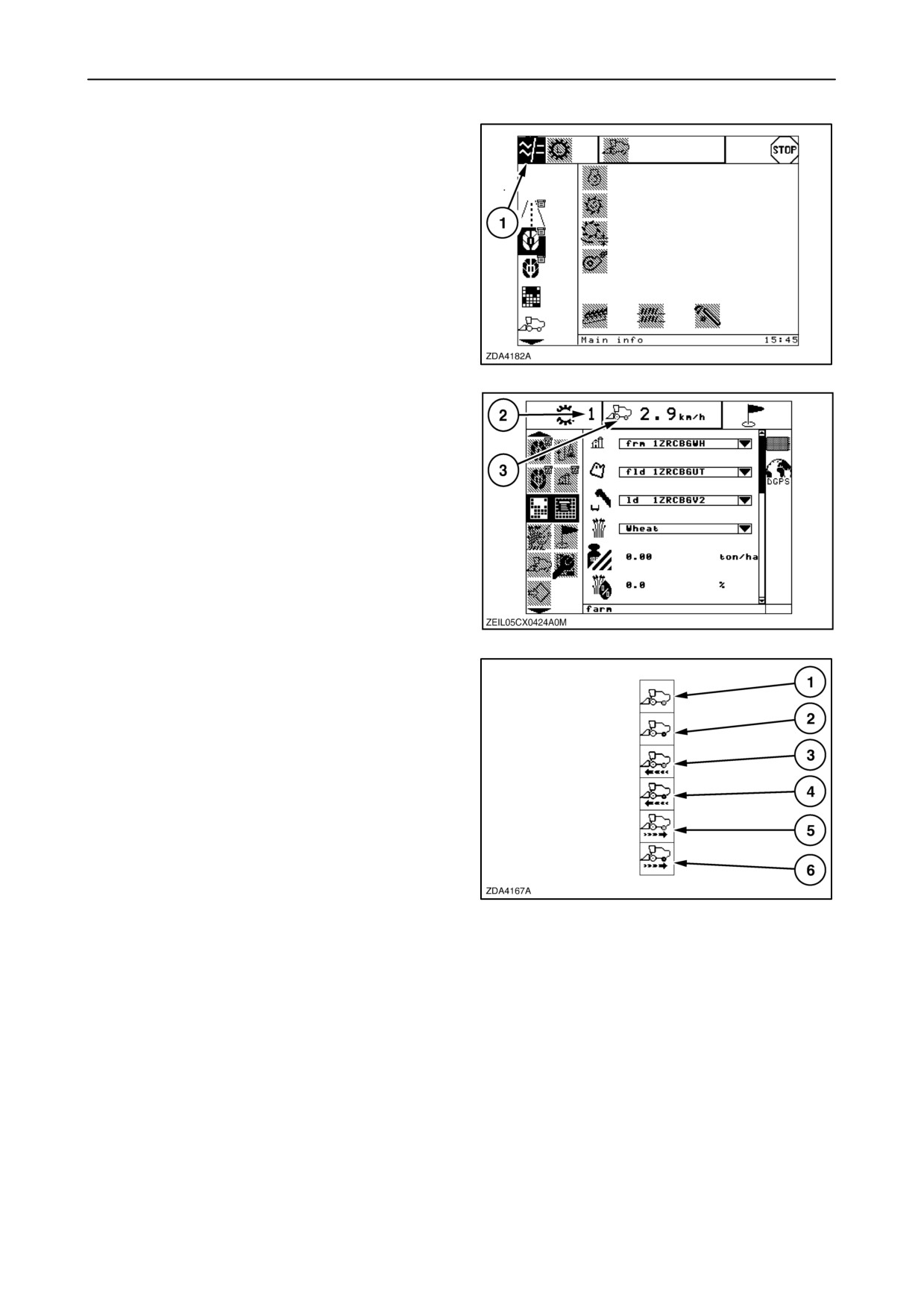
The following information is in the indicator bar:
1. Network connection: Yes/No
(symbol
1 is
appearing when no network connection).
56
2. Selected gear (1 - 2 - N - 3 - 4)
3. Drive
57
The icon shows the drive direction and the status of
the four wheel drive as follows:
1. Neutral
2. Neutral with 4 wheel-drive engaged
3. Forward
4. Forward with 4 wheel-drive engaged
5. Reverse
6. Reverse with 4 wheel-drive engaged
58
2-42
SECTION 2 - CONTROLS, INSTRUMENTS AND OPERATION
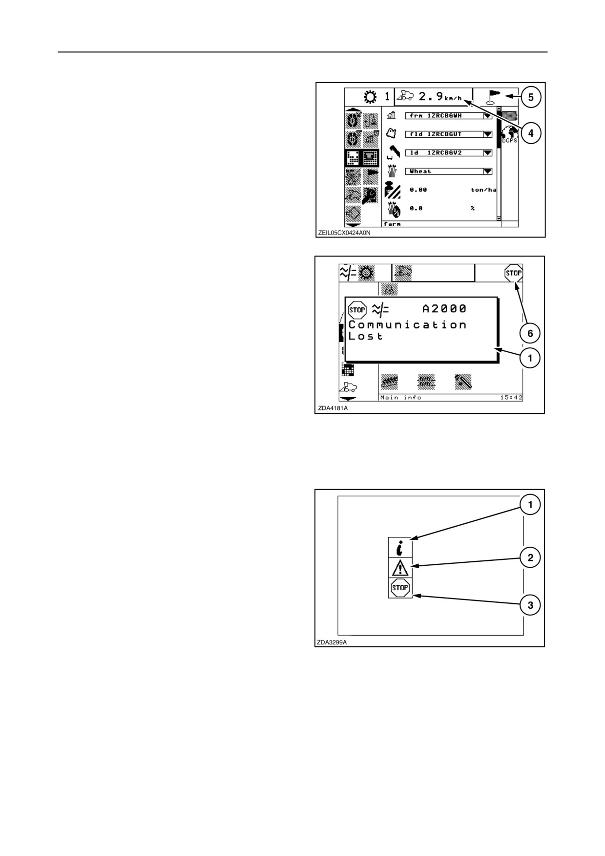
4. Ground speed (km/h or mph)
5. A flag is appearing when a data card is installed
which has markers information on it.
59
6. Active alarms and/or errors
(Low, Medium or High priority).
These icons appear on the screen together with
pop-up
1 screen with more information on the
alarm/error.
• If a
“Low” priority alarm: The pop-up screen
disappears from the display after a few seconds,
the symbol in the indicator bar stays on the
display to warn the operator there is an
alarm/error.
• If a “Medium” or “High” priority alarm: The pop-up
60
screen stays on the display until they press on the
“escape” button, the symbol in the indicator bar
stays on the display to warn the operator there is
an alarm/error.
Alarms and errors are classified in three levels.
According to the importance of the alarm/error,
following icons appear in the indicator bar:
1. Low priority alarm/error
2. Medium priority alarm/error
3. High priority alarm/error
61
2-43
SECTION 2 - CONTROLS, INSTRUMENTS AND OPERATION
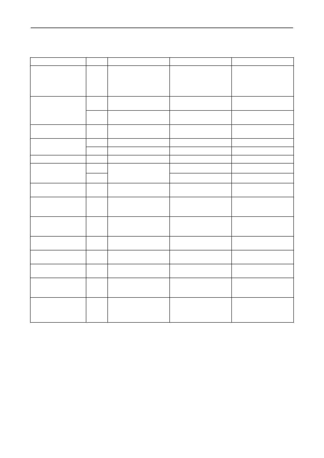
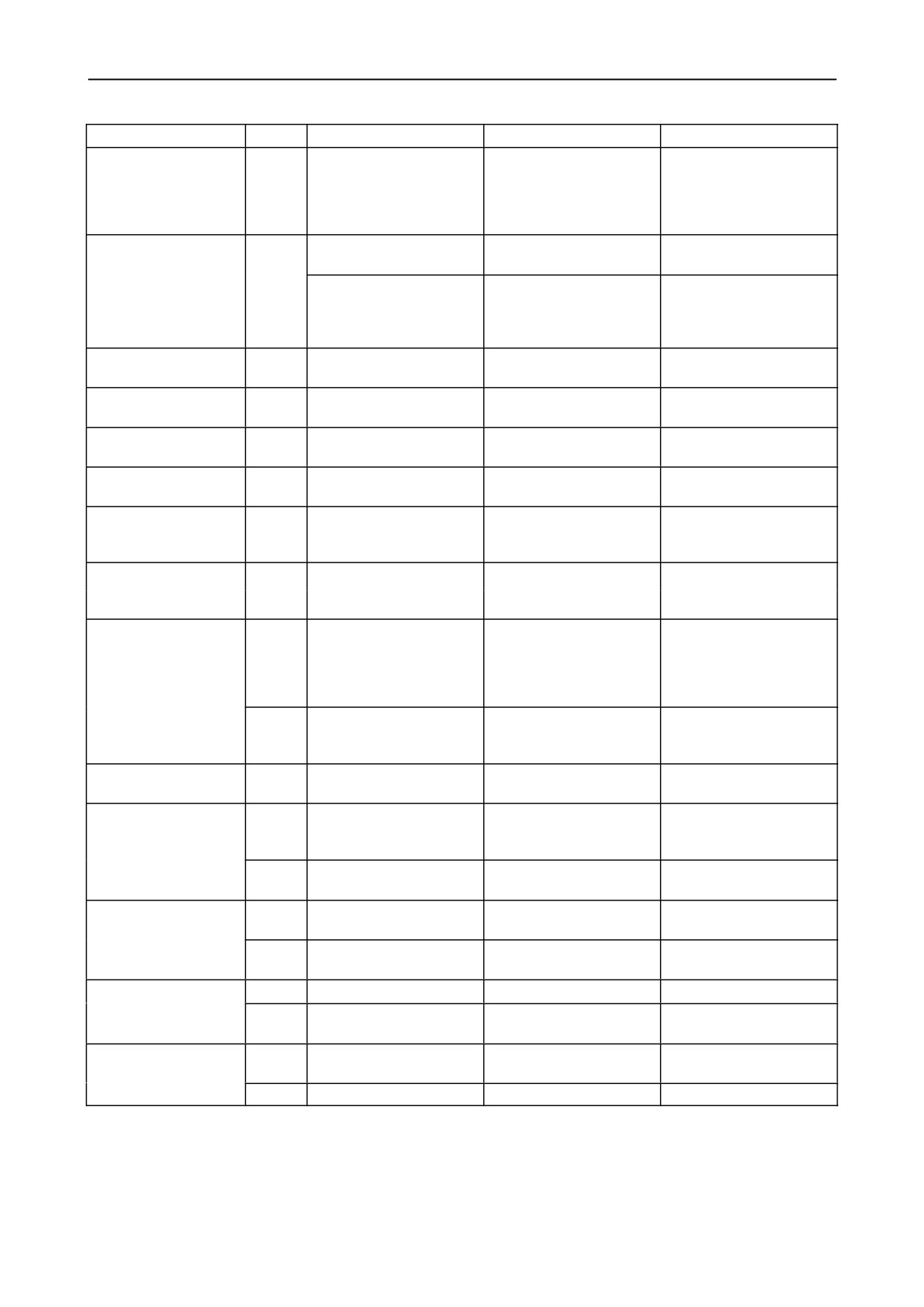
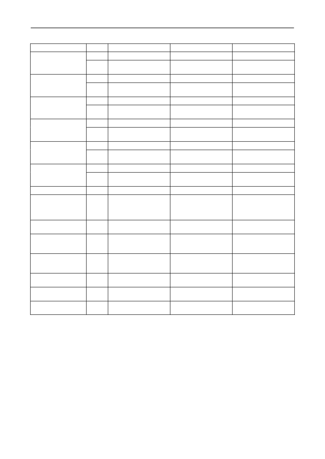
The following is a list of the alarms with the priority, condition, activation and reset measure.
Description
Priority
Check condition
Activation
Resetting
A0000 Engine coolant
High
Engine running and tem-
2 sec > 102 °C (216°F)
2 sec < 102 °C (216°F)
temperature HIGH
perature sensor not faulty
electrical engine
electrical engine
2 sec > 110 °C (230°F)
mechanical engine
2 sec < 110 °C (230°F)
or engine shut down
mechanical engine
A0001 Engine oil
High
CNH engine running
2 sec > 126 °C (259°F)
2 sec < 126 °C (259°F)
temperature HIGH
or engine shutdown
High
Iveco engine running
3 sec > 126 °C (259°F)
2 sec < 126 °C (259°F)
or engine shutdown
A0002 Engine Oil
High
Engine running and pres-
3 sec < 1 bar (14.5psi)
0.5 sec >/= 1 bar (14.5psi)
pressure LOW
sure sensor not faulty
or engine shutdown
A0003 Battery Voltage
Low
Engine rpm > 500 rpm
8 sec < 12 V
2 sec > 12.5 V
LOW
Low
Engine rpm < 500 rpm
8 sec < 10 V
2 sec > 10.5 V
A0004 Fuel level LOW
Low
Level sensor not faulty
4 sec < 10 %
4 sec > 12 %
A0005 Air filter
Low
Sensor configuration set
10 sec > 625 mm H 2O
2 sec </= 625 mm H 2O
BLOCKED
to not installed and air fil-
Low
10 sec < 0.25 V
2 sec >/= 0.25 V
ter switch not faulty
A0006 Gearbox tem-
High
Engine running
2 sec > 90°C (194°F)
2 sec </= 90°C (194°F)
perature HIGH
A0007 Hydraulic
High
10 sec > 90°C (194°F)
3 sec < 85°C (185°F)
reservoir temperature
HIGH
A0008 Hydrostatic mo-
High
Sensor configuration set
10 sec > 105°C (221°F)
3 sec < 100°C (212°F)
tor temperature HIGH
to installed and hydro tem-
perature sensor not faulty
A0009 Return filter
Low
10 sec < 1.8 V and
2 sec > 1.8 V and < 25 °C
blocked
>/= 25°C
A0010 Gearbox filter
Low
10 sec < 1.8 V and
2 sec < 1.8 V and < 25 °C
blocked
>/= 25°C
A0011 Hydraulic reser-
High
Reservoir switch not faulty
4 sec > 1.8 V
0.5 sec < 1.8 V
voir level LOW
A0012 Control
High
Engine running for 3 sec
2 sec < 20 bar
0.5 sec >/= 20 bar
pressure LOW
and control pressure not
faulty
A0013 Gearbox clutch
High
Sensor configuration set
0.1 sec >/= 130 °C
2 sec </= 120°C
temperature HIGH
to installed and gearbox
(266°F)
clutch temperature sensor
not faulty
(*) can be configured in InfoViewt
2-44
SECTION 2 - CONTROLS, INSTRUMENTS AND OPERATION
Description
Priority
Check condition
Activation
Resetting
A0014 Straw elevator
High
Reverser sensor engaged
straw elevator engaged +
10 sec reverser sensor+
reverser ENGAGED
0.5 sec reverser sensor or
straw elevator disengaged
straw elevator engage-
and
ment + reverser sensor or
reverser switch
reverser switch
A0015 Seat switch
Med
Not seated for 5 sec
0.01 sec straw elevator
Straw elevator disen-
OPEN
engaged
gaged for 10 sec.
Not seated
Straw elevator engage
Disengage straw elevator
switch transition from low
engage switch
to high (attempting to
engage straw elevator)
A0016 Engine RPM
Med
Threshing running
2 sec < 1950 rpm (*)
2 sec > 2000 engine rpm
LOW
A0020 Set parking
High
Engine on, MFH neutral,
Operator not in seat for
Operator in seat for
brake ALARM
Brake off
2 sec
0.5 sec
A0021 Rear ladder
High
Engine running
Ladder down for 1 second
Ladder up for 0.5 second
DOWN
A0022 Unload
Low
Unloading engaged
Unloading not engaged
engaged
A0028 Grain tank
Low
Cover switch open
field mode: > 15 km/h and
0 sec in field mode
covers OPEN
covers open
road mode: covers open
A0029 Unloading tube
Low
Road mode or > 15 km/h
2 sec unload tube open
2 sec unload tube close
OPEN
(9mph) and ground speed
sensor NOT faulty
A0030 Grain bin FULL
High
Threshing engaged, no
1 sec the 2 sensors acti-
1 sec both sensors not
unloading and straw ele-
vated
activated
vator engaged, moving
forward and grain bin
sensor NOT faulty
Low
Threshing engaged, no
1 sec the 2 sensors acti-
1 sec both sensors not
unloading and grain bin
vated
activated
sensor NOT faulty
A0032 Straw hood
High
Threshing engaged
blocked for 1 sec
not blocked for 3 sec
blocked
(input < 1.8V)
(input > 1.8V)
A0033 Parking brake
High
Parking brake switch in er-
MFH not in neutral
MFH in neutral
ON
ror, engine running and
parking brake engaged
Med
Parking brake ON and
MFH not in neutral
MFH in neutral
engine running
A0034 Straw walker
High
Threshing running
1 sec < 113 rpm
1 sec >/= 113 rpm
RPM LOW
Med
Threshing running
1 sec < 80 % of set speed
3 sec >/= 80 % of set
speed
A0036 Drum RPM
High
Threshing running
1 sec < 100 rpm
3 sec >/= 100 rpm
LOW
Med
Threshing running
1 sec < 80 % of set speed
3 sec >/= 80 % of set
speed
A0038 Rotary separa-
High
Threshing running
1 sec < 179 rpm
3 sec > 179 rpm
tor RPM LOW
Med
Threshing running
1 sec < 80 % of set speed
3 sec > 80 % of set speed
2-45
SECTION 2 - CONTROLS, INSTRUMENTS AND OPERATION
Description
Priority
Check condition
Activation
Resetting
A0039 Beater RPM
High
Threshing running
1 sec < 100 rpm
3 sec >/= 100 rpm
LOW
Med
Threshing running
1 sec < 80 % of set speed
3 sec >/= 80 % of set
speed
A0040 Grain elevator
High
Threshing running
1 sec < 100 rpm
3 sec > 100 rpm
RPM LOW
Med
Threshing running
1 sec < 80 % of set speed
3 sec >/= 80 % of set
speed
A0041 Fan RPM LOW
High
Threshing running
1 sec < 130 rpm
3 sec > 130 rpm
Med
Threshing running
1 sec < 80 % of set speed
3 sec >/= 80 % of set
speed
A0042 Chopper RPM
High
Threshing running
1 sec < 100 rpm
3 sec >/= 100 rpm
LOW
Med
Threshing running
1 sec < 80 % of set speed
3 sec >/= 80 % of set
speed
A0043 Returns left
High
Threshing running
1 sec < 195 rpm
3 sec > 195 rpm
RPM LOW
Med
Threshing running
1 sec < 80% of set speed
3 sec >/= 80% of set
speed
A0044 Returns right
High
Threshing running
1 sec < 195 rpm
3 sec > 195 rpm
RPM LOW
Med
Threshing running
1 sec < 80% of set speed
3 sec >/= 80% of set
speed
A0047 Check brakes
Med
5 sec < 0.69 V
10 sec > 0.69 V
A0051 Road mode
Low
Road mode selected
Covers open, header up/
Stop attempting to engage
selected
down / tilt, straw elevator,
device then disengage
rear axle, thresher, unload
road mode
on / open, reel up / down
A0052 Flow sensor out
Low
Yield monitor type configu-
1sec < 0.2 V or > 5.2 V
1sec >0.2 V or < 5.2 V
of range
ration not set to 0
A0057 Battery voltage
Med
Battery voltage > 15.5 V
Battery voltage > 15 V for
high
for 8 sec
2 sec
A0061 Thresher disen-
Med
gaged
(No speed signal)
A0062 Autopilot
Med
switched to manual
A0063 End of crop
Med
detected
A0064 Autopilot signal
Med
detected
2-46
SECTION 2 - CONTROLS, INSTRUMENTS AND OPERATION
Description
Priority
Check condition
Activation
Resetting
A0077 Self-levelling
Med
Shoe actuator running in
Shoe position stable
shoe NOT LEVEL
Threshing engaged & SL
one direction for 15 sec
installed
Low
Shoe position sensor
Shoe position sensor and
faulty or lateral inclination
lateral inclination sensor
sensor faulty
OK
A0079 Grain tank
Med
Threshing engaged, cov-
Bubble-up sensor
Bubble-up sensor
covers CLOSED
ers installed, bubble-up
indicates the covers are
indicates the covers are
sensor installed and en-
closed
open
gine running
Threshing engaged, cov-
Threshing engaged, en-
Covers no longer opening
ers installed, bubble-up
gine running and covers
sensor not installed and
open
engine running
A0080 Gearshift NOT
Low
Not able to get to shift to
Selected gear found
successful
selected gear in 6 sec.
A0081 Hydrostatic
High
Engine running for 1 sec
1 sec < 1.8 V
0.5 sec > 1.8 V
charge pressure LOW
A0082 Auto HHC Dis-
Low
Auto HHC activated
Straw elevator angle >
Alarm only displayed for 2
abled
max. stubble height
sec.
A0083 Hydro speed
Low
Sensor configuration set
10 sec > 95 °C
3 sec < 90°C
limitation
to installed and hydro
temp. sensor not faulty
A0117 Header need to
Med
Header has not been
Alarm is displayed for 10
be defined
installed on the combine
seconds
before.
A0120 Upper sieve not
Med
Upper sieve position is not
Upper sieve position is
in position
within 1 mm of the upper
within 1 mm of the upper
sieve position set point for
sieve position set point
4 sec.
A0123 Road mode not
Med
Road mode switch placed
Road mode not engaged,
Road mode engaged
allowed
into the road mode posi-
unload engaged or unload
tion
tube not cradled or straw
elevator, reverser, thresh-
er, rear wheel assist en-
gaged or concave moving
A0124 Lower sieve not
Med
Lower sieve position is not
Lower sieve position is
in position
within 1 mm of the lower
within 1 mm of the lower
sieve position set point for
sieve position set point
4 sec.
A0125 Upper sieve
Low
Remote upper sieve con-
Upper sieve has never
Calibrate upper sieve
calibration required
figuration set to installed
been calibrated
A0126 Lower sieve
Low
Remote lower sieve con-
Lower sieve has never
Calibrate lower sieve
calibration required
figuration set to installed
been calibrated
2-47
SECTION 2 - CONTROLS, INSTRUMENTS AND OPERATION
Description
Priority
Check condition
Activation
Resetting
A1000 Datalogger PLD
Can’t open marker file
Contact your New Holland
fault
Dealer
A1001 Datalogger EE
Can’t open marker file
Contact your New Holland
fault
Dealer
A1002 Error On log file
Can’t open marker file
Contact your New Holland
Can’t create default mark-
Dealer
er file
Can’t open log file
99 log files already on the
card
A1003 CCM not send-
CCM’s not sending re-
Contact your New Holland
ing needed messages
quired messages
Dealer
A1004 Error on job file
Can’t open or corrupt ob-
Contact your New Holland
ject file
Dealer
A1005 Error on marker
Corrupt marker file
Contact your New Holland
file
Dealer
A1006 Datacard full
A1010 GPS signal lost
A1011 DGPS correc-
tion signal lost
A2000 No CAN
High
CAN open
Contact your New Holland
Dealer
A2001 MDM offline
Low
InfoViewt monitor is of-
Contact your New Holland
fline
Dealer
A2002 CCM1 offline
Low
No can messages re-
Contact your New Holland
ceived from CCM1 for
Dealer
5 seconds
A2003 CCM2 offline
Low
No can messages re-
Contact your New Holland
ceived from CCM2 for
Dealer
5 seconds
A2004 CCM3 offline
Low
CCM3 installed
No can messages re-
Contact your New Holland
ceived from CCM3 for
Dealer
5 seconds
A2005 RHM offline
Low
No can messages re-
Contact your New Holland
ceived from RHM for
Dealer
5 seconds
A2006 SSM offline
Low
No can messages re-
Contact your New Holland
ceived from SSM for
Dealer
5 seconds
A2007 ECU offline
Low
Engine control unit
No can messages re-
Contact your New Holland
installed
ceived from ECU for
Dealer
5 seconds
A2008 HHC offline
Low
No can messages re-
Contact your New Holland
ceived from HHC for
Dealer
5 seconds
A2009 GPS offline
Low
Global Position System
No can messages re-
Contact your New Holland
installed
ceived from GPS for
Dealer
5 seconds
A2010 DLU offline
Low
Data Logger Unit installed
No can messages re-
Contact your New Holland
ceived from DLU for
Dealer
5 seconds
2-48
SECTION 2 - CONTROLS, INSTRUMENTS AND OPERATION
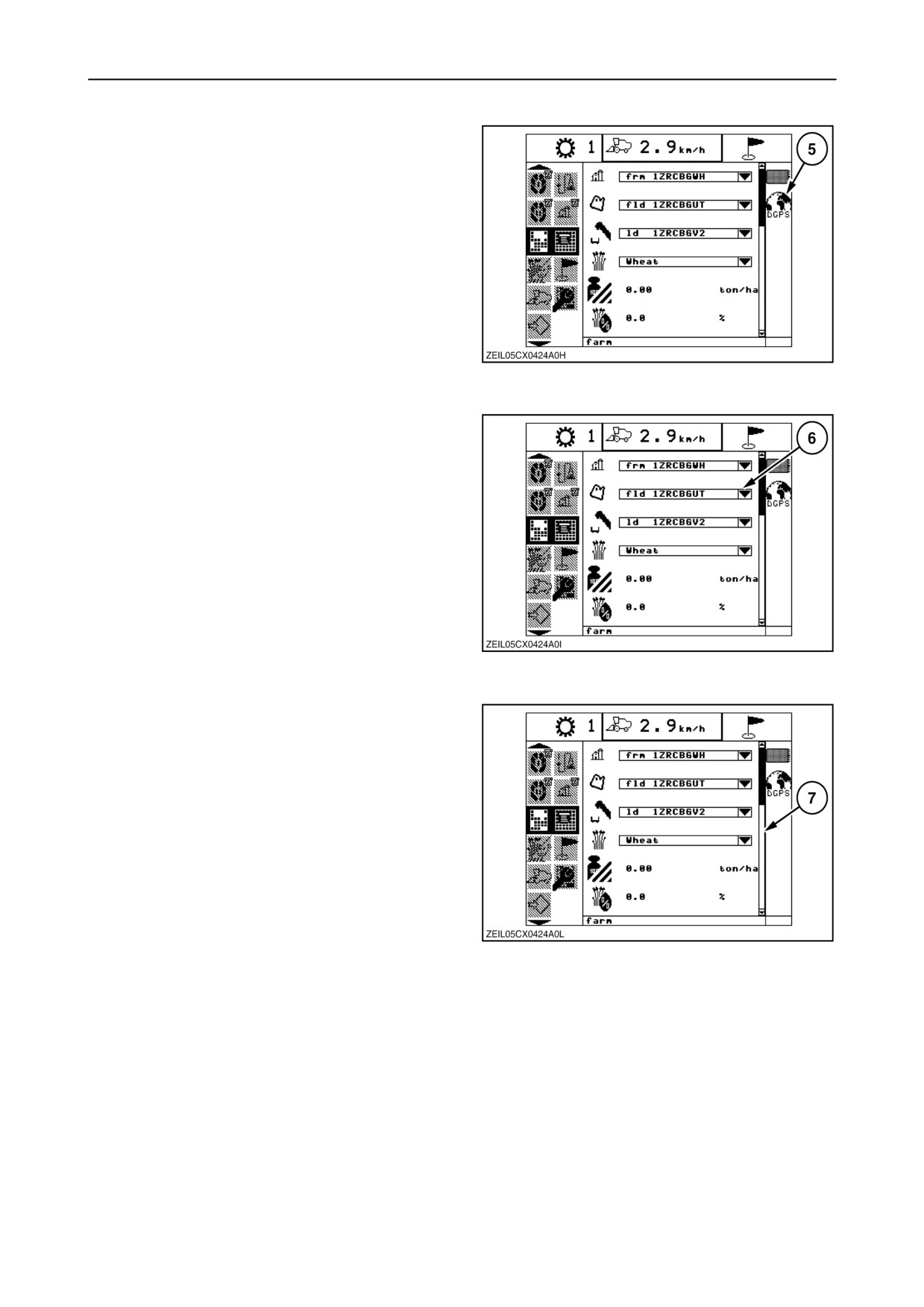
5. STATUS BAR
On the right-hand side of the display, status bar 5 will
show the status of different components, i.e. front
operating lights, rear operating lights, revolving flash
lights, data-card (D)GPS...
NOTE: The status bar is only visible when there is a
symbol. If there is nothing to display in the status bar,
the complete bar removes from the screen.
62
6. INFORMATION BOX
In information box 6, in the middle of the display,
information is shown to the operator. Depending on
the selected menu and/or sub menu, different
information is shown.
63
7. SCROLL BAR
Scroll bar
7 appears on the screen when the
information box contains more information than is
visible on the screen. The bar indicates the position
on the information ladder.
64
2-49