New Holland CX720, CX740, CX760, CX780, CX820, CX840, CX860, CX880. Operator's Manual - page 2
SECTION 1 - GENERAL INFORMATION AND SAFETY
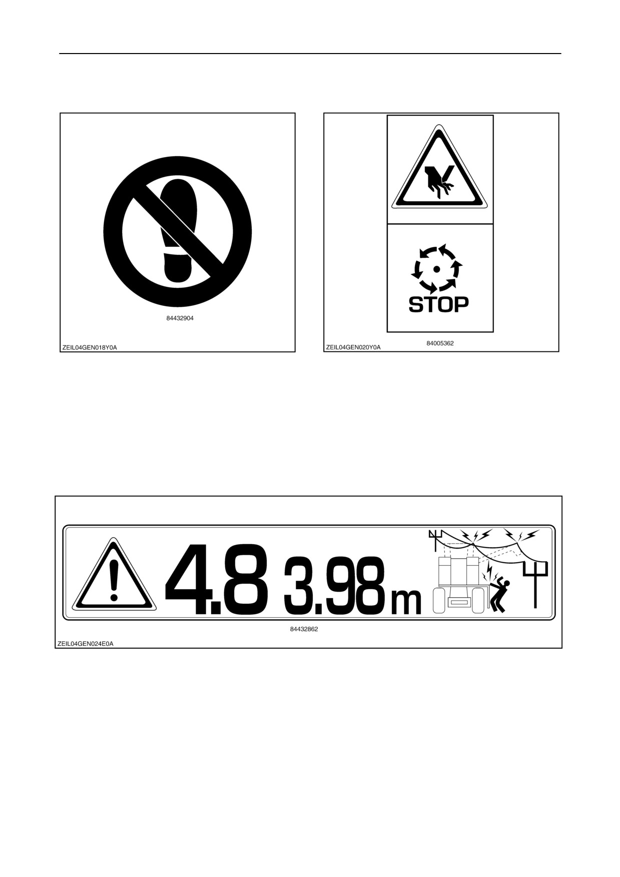
Decal 21
Decal 23
Don’t place foot.
Wait until all machine components have stopped
completely before touching them.
Decal 22
Overhead power lines + height indication.
1-24
SECTION 1 - GENERAL INFORMATION AND
SAFETY
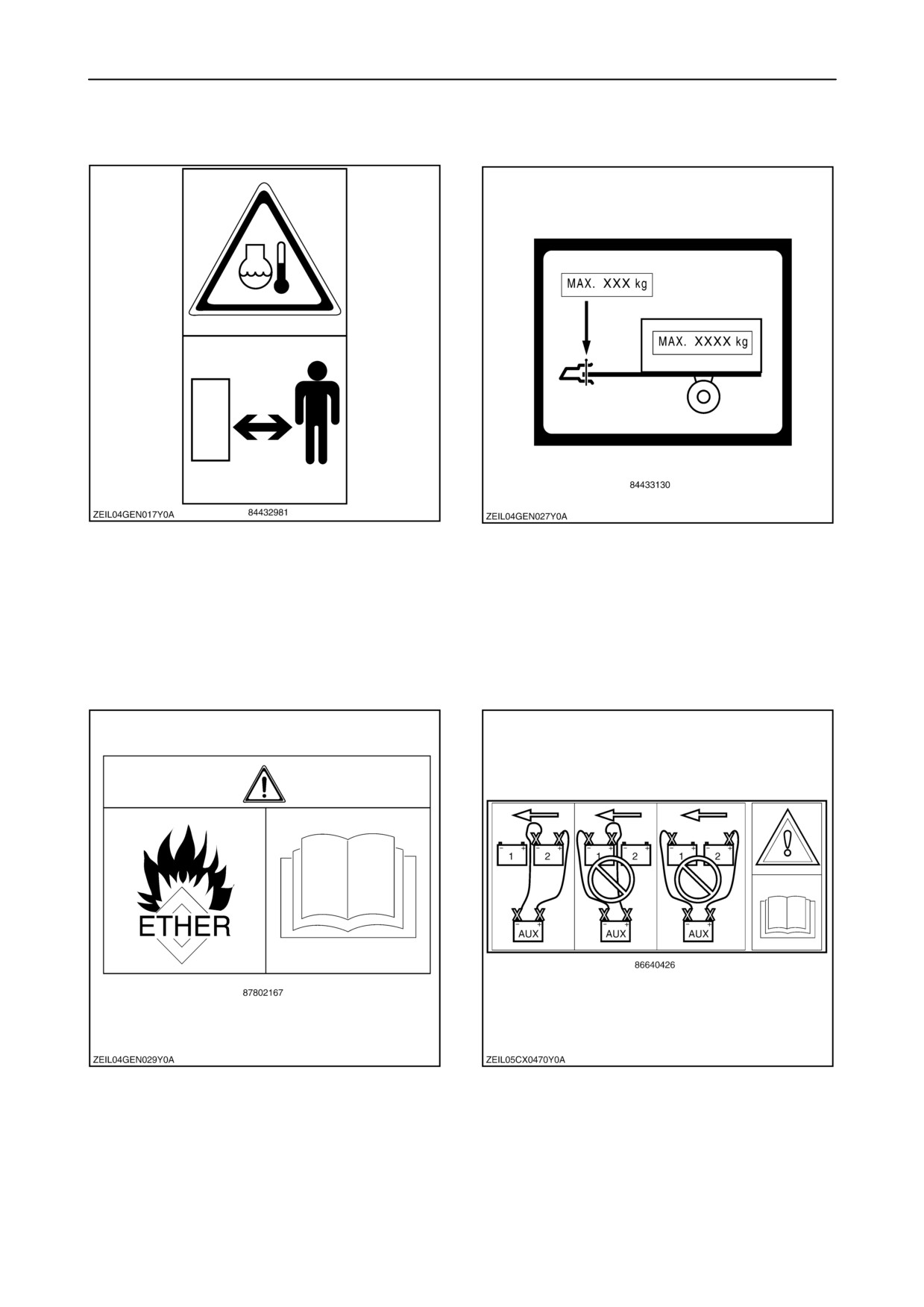
Decal 24
Decal 25
Hot coolant.
This plate indicates:
1. The maximum allowed vertical force.
2. The maximum allowed horizontal pull force of the
hitch.
Decal 26
Decal 27
Ether warning
Boost only to rear battery.
1-25
SECTION 1 - GENERAL INFORMATION AND SAFETY
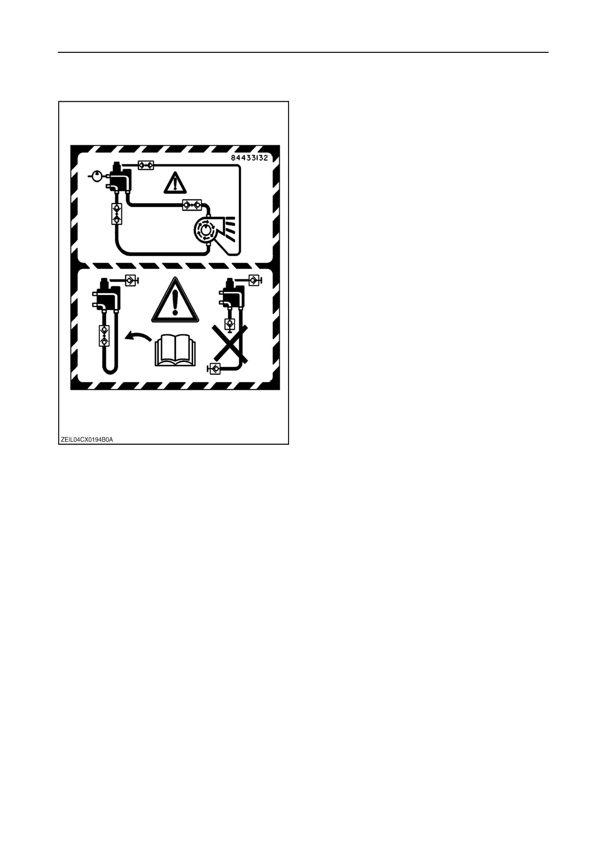
Decal 28
When remove the chaff blower, connect the hydraulic
couplers as shown.
1-26
SECTION 1 - GENERAL INFORMATION AND SAFETY
SAFETY DECALS (AUSTRALIA)
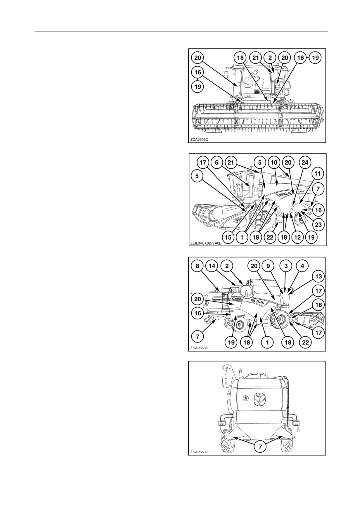
The following safety decals have been placed on your
machine in the areas indicated. They are intended for
your personal safety and for those working with you.
16
Please take this manual and walk around your
machine, noting the location of the decals and their
significance.
17
Review these decals and the operating instructions
detailed in this Manual with the machine operators.
18
Keep the decals clean and legible. If they become
damaged or illegible, obtain replacements from your
New Holland dealer.
19
1-27
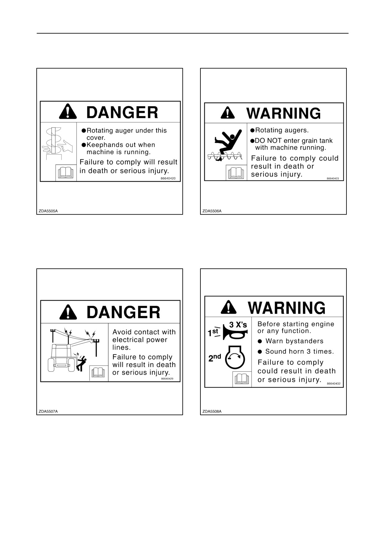
SECTION 1 - GENERAL INFORMATION AND
SAFETY
Decal 1
Decal 2
Decal 3
Decal 4
1-28
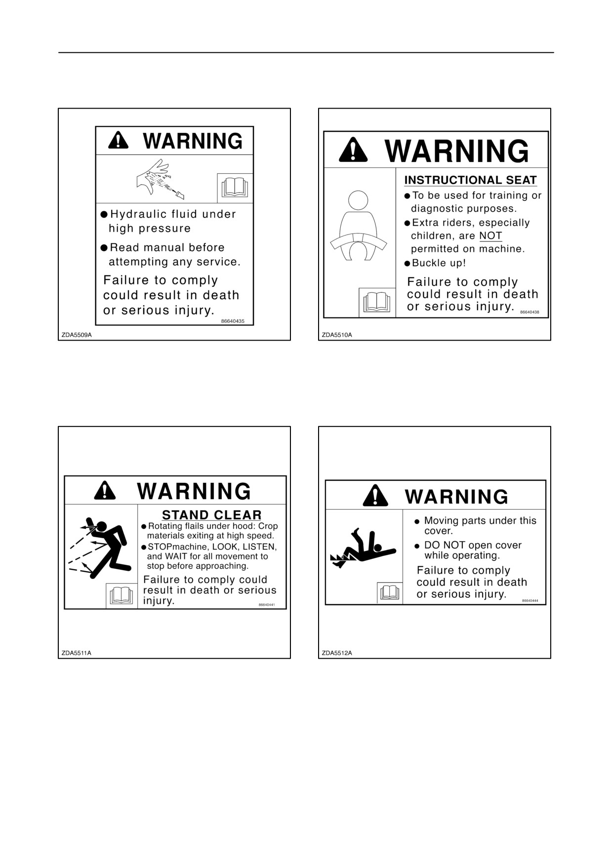
SECTION 1 - GENERAL INFORMATION AND
SAFETY
Decal 5
Decal 6
Decal 7
Decal 8
1-29
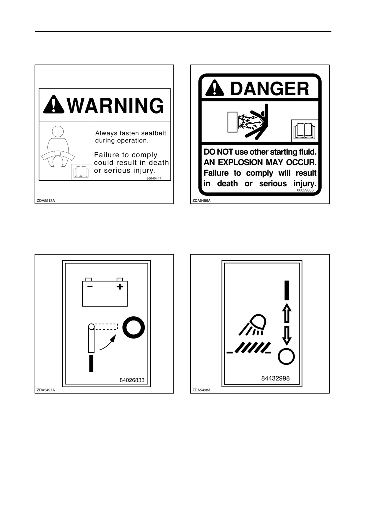
SECTION 1 - GENERAL INFORMATION AND SAFETY
Decal 9
Decal 10
Decal 11
Decal 12
1-30
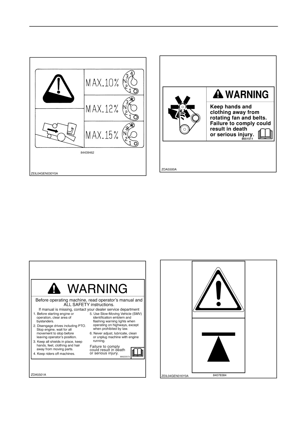
SECTION 1 - GENERAL INFORMATION AND SAFETY
Decal 13
Decal 14
To prevent runaway of the combine (i.e. when the
ground speed increases during downhill driving and
it is impossible to reduce speed with the ground
speed control lever), it is necessary to shift into a
lower gear appropriate to the steepness of the hill
before starting the descent.
Decal 15
Decal 16
Jack up point
1-31
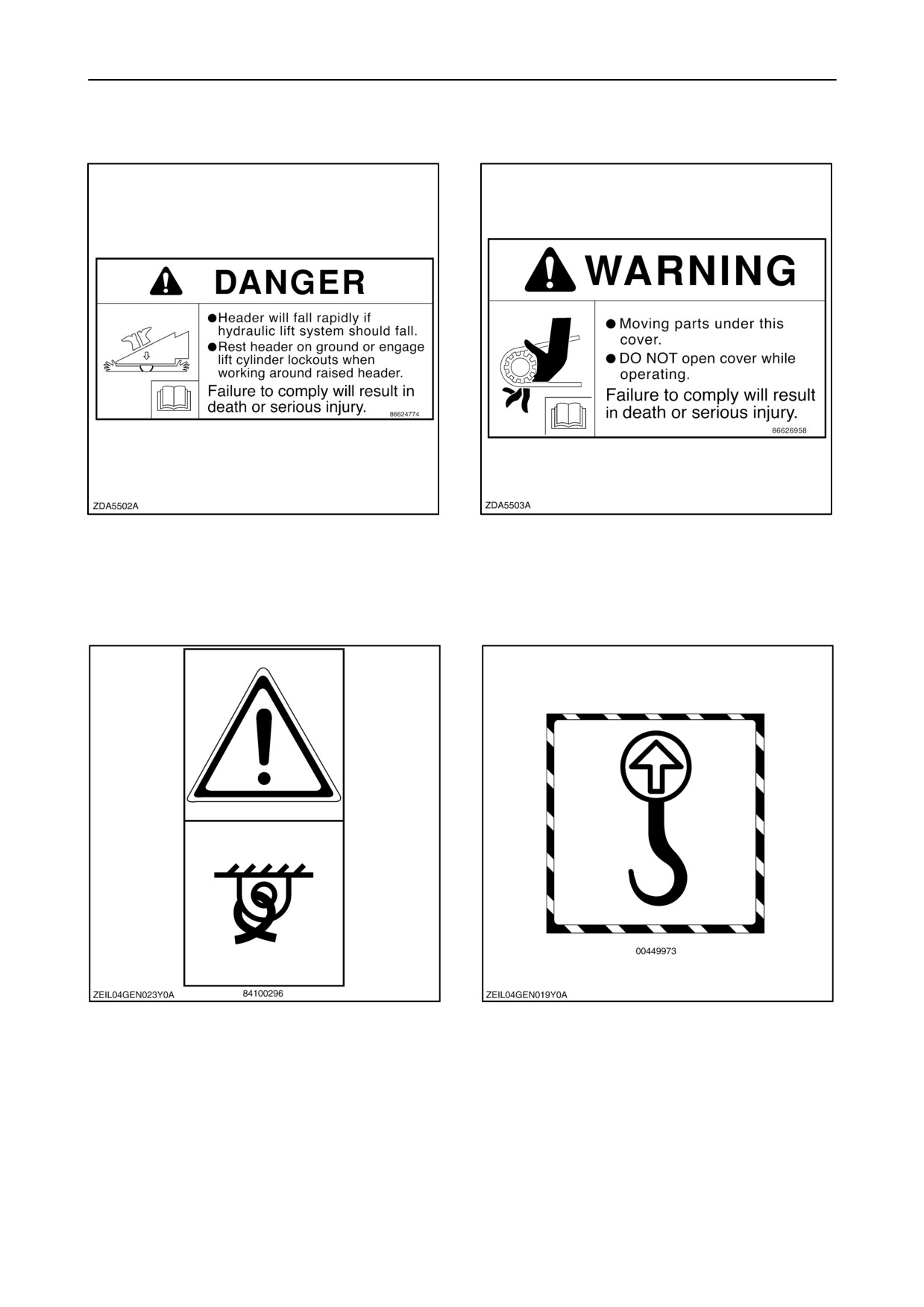
SECTION 1 - GENERAL INFORMATION AND SAFETY
Decal 17
Decal 18
Decal 19
Decal 20
Tie-down eye.
Lifting eye / pulling eye.
1-32
SECTION 1 - GENERAL INFORMATION AND SAFETY
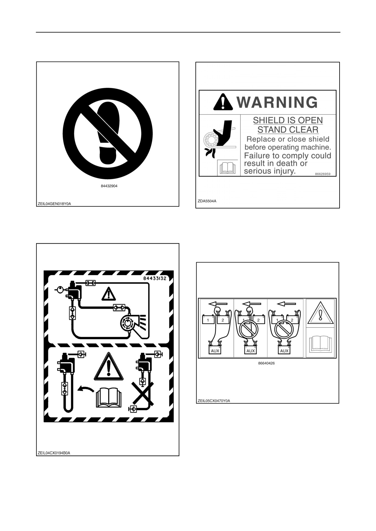
Decal 21
Decal 22
Don’t place foot.
Decal 23
Decal 24
Boost only to rear battery.
When remove the chaff blower, connect the hydraulic
couplers as shown.
1-33
SECTION 1 - GENERAL INFORMATION AND SAFETY
ACCESS TO MACHINE COMPONENTS
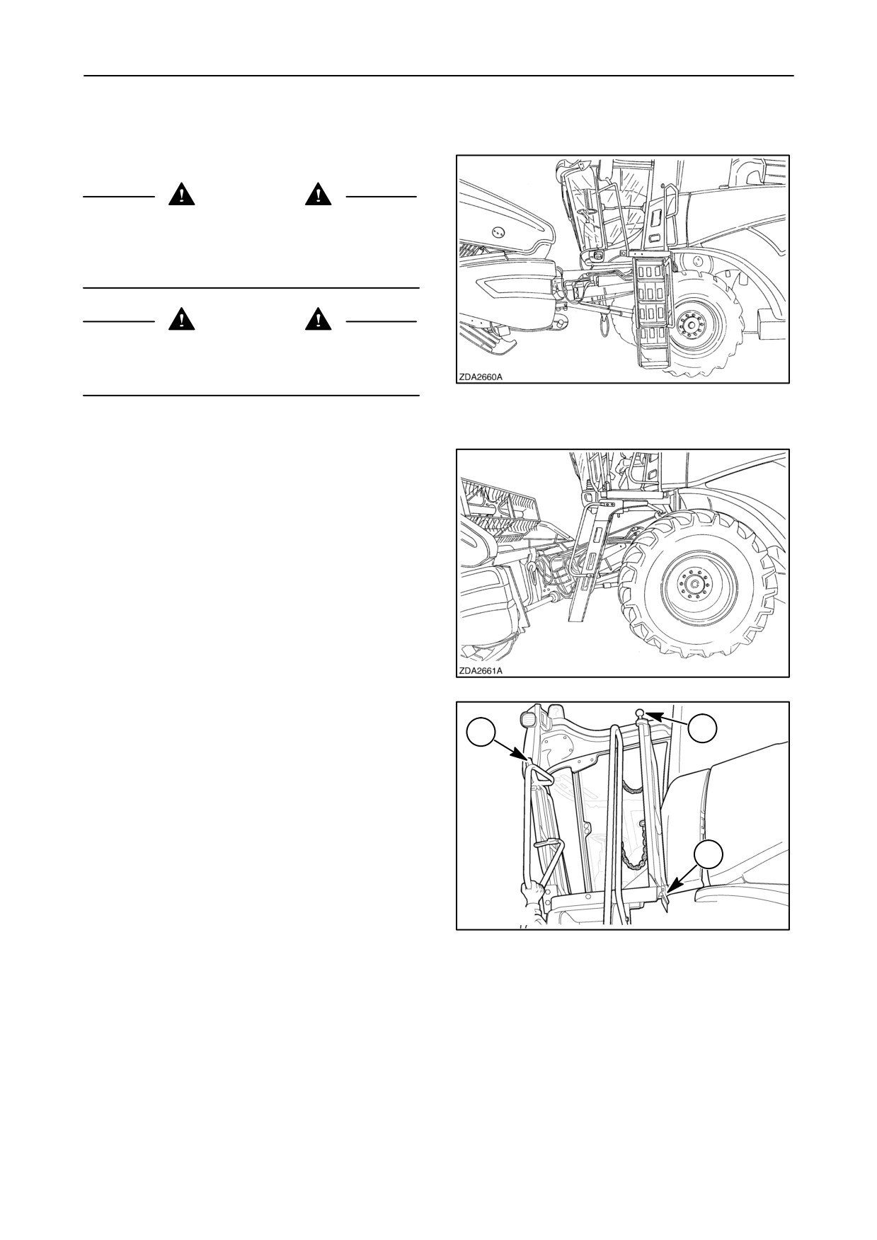
1. Access to operator’s platform
DANGER
Never allow anyone to stand or hang on the combine
access ways while the combine is in motion. These
access ways are only provided for entering and
servicing the (stopped) combine in a safe way.
CAUTION
Always mount and leave the combine in a safe way,
i.e. use the steps and guard rails provided and
maintain a 3-point contact at all times.
20
To turn the ladder in front of the wheel for road
transport, proceed as follows:
21
1. Lift the front, top hand rail as shown from the
ground, or by lifting handle (1) from the upper
3
1
platform, and rotate the rail forward.
2. Pull down on the ladder latch handle (2) from the
ground or press down on the upper knob (3) from
the upper platform and swing the ladder forward.
Release the latch and swing until the ladder
2
latches in the forward position.
To return to the side position reverse steps 1 and 2
50021821
being sure the ladder latches into position before
stepping onto the ladder.
22
1-34
SECTION 1 - GENERAL INFORMATION AND SAFETY
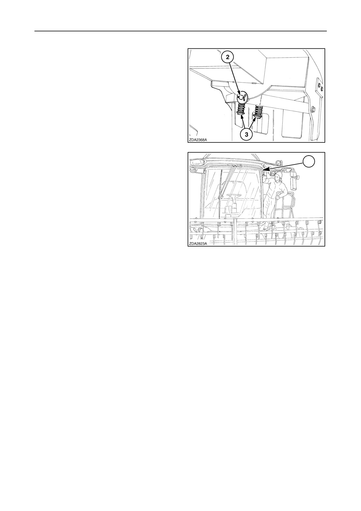
With the ladder in the side position for field operation,
the ladder can pivot, at 2, when the combine is
advancing or reversing and the ladder contacts an
obstacle.
The pivoting force is adjusted with springs 3. The
length of the springs should be 63 mm (2-1/2”).
Be sure to return the ladder to the center position
before stepping onto the ladder.
23
3. Access to straw elevator to enable cleaning of the
cab windscreen.
1
Raise the header to its highest position and engage
the header safety latch. Step on the straw elevator
(is foreseen with antislip strips) and keep your hand
on rail 1 on top of the cab.
24
1-35
SECTION 1 - GENERAL INFORMATION AND SAFETY
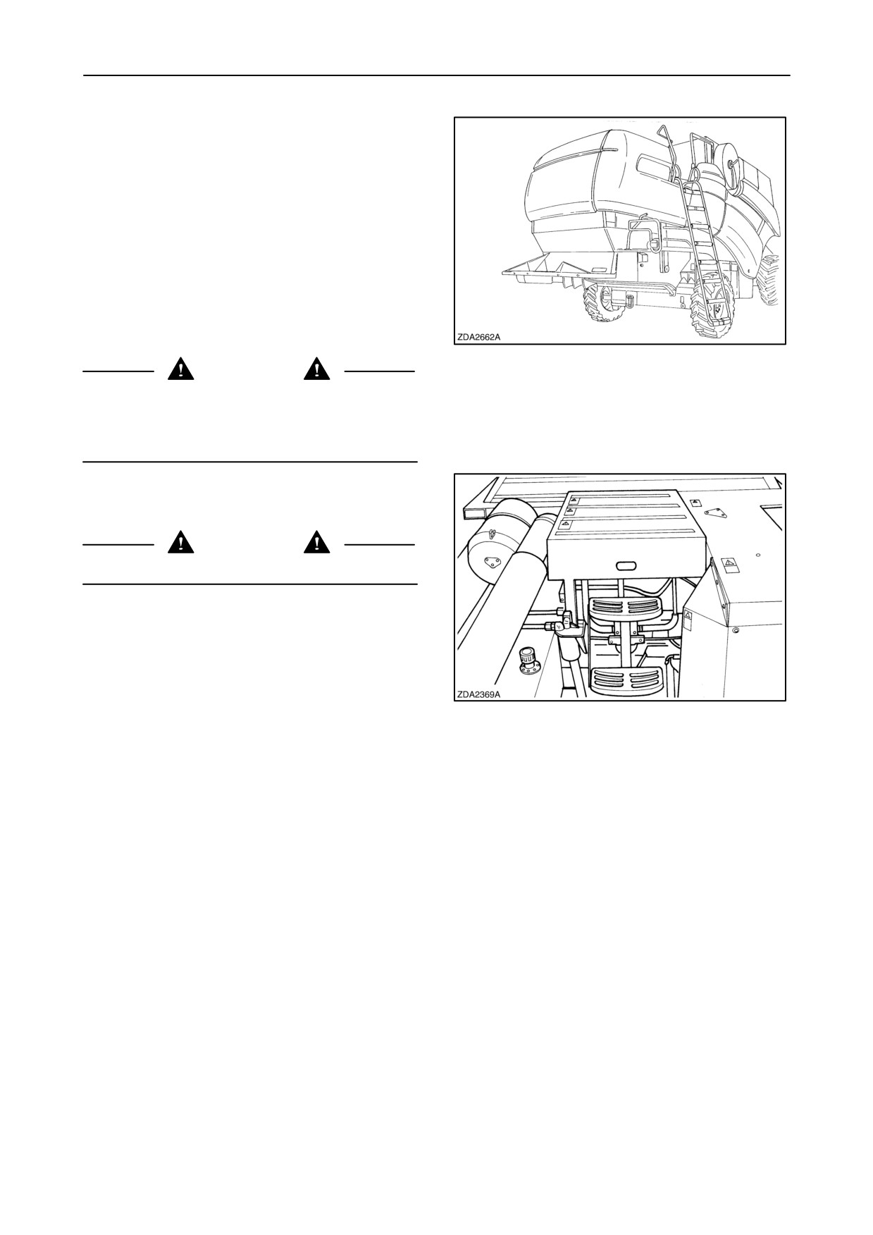
4. Pull the rear ladder down to have access to the
engine compartment and fuel tank filler cap.
Lowering the rear ladder during the threshing
mechanism and/or unloading system is engaged will
cause to stop this functions. It is, however impossible
to start the threshing mechanism and/or the
unloading system while the rear ladder is in the
lowered position.
25
CAUTION
Rear ladder must be in the raised position during
travel on public roads. Severe equipment damage
could result if ladder is left in the lowered position
during travel.
5. Step and antislip strips on the engine cover are
provided to have access to the grain tank at the
rear side.
CAUTION
Never stand up on the engine cover.
26
1-36
SECTION 1 - GENERAL INFORMATION AND SAFETY
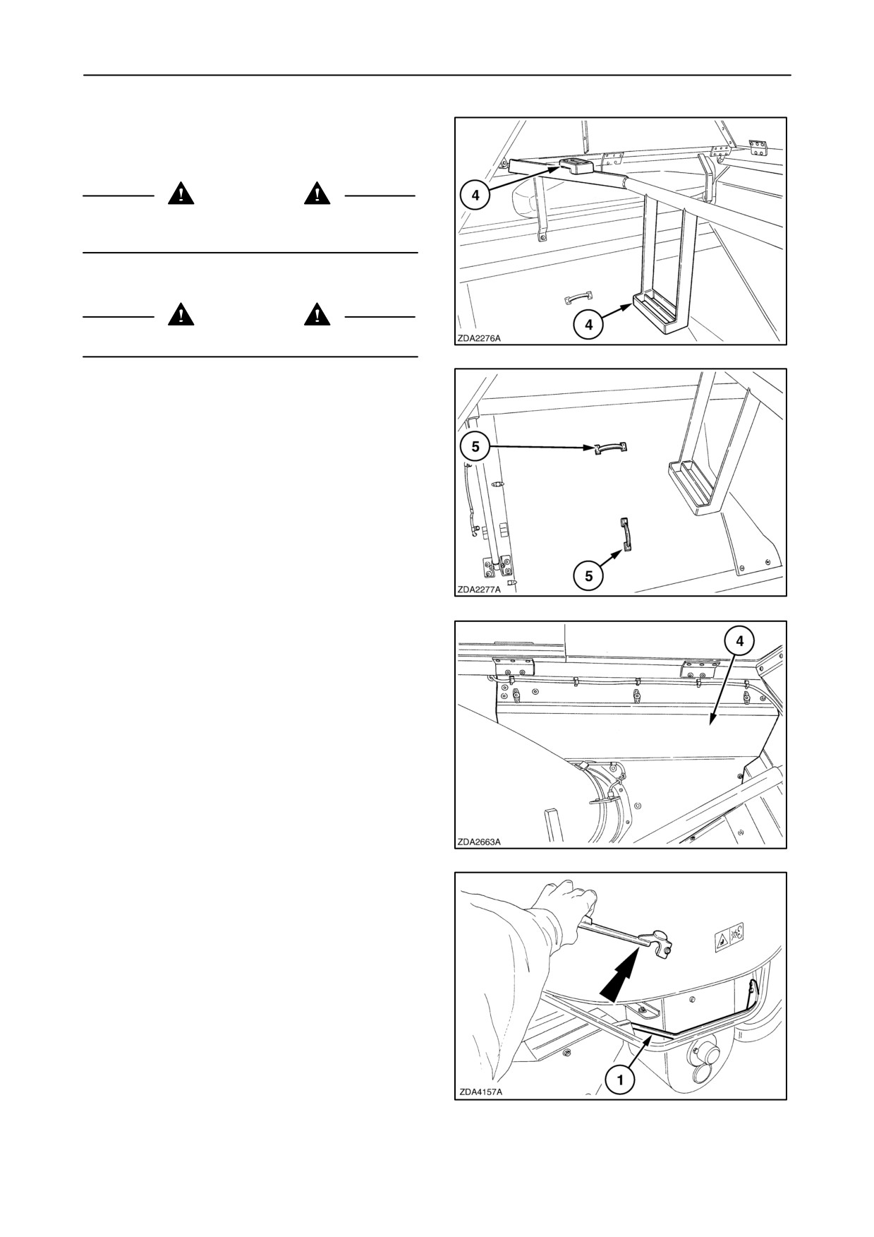
6. The grain tank is accessible through the open
grain tank covers using the steps (4).
CAUTION
Shut off the engine and remove the ignition key
before entering the grain tank.
CAUTION
Never climb in the grain tank from the front side.
27
7. Once inside the grain tank, remove the cover (5)
to gain access to the engine compartment.
28
8. Remove the cover (4) to gain access to the grain
flow sensor (if installed).
29
9. Shielding (left and right-hand side).
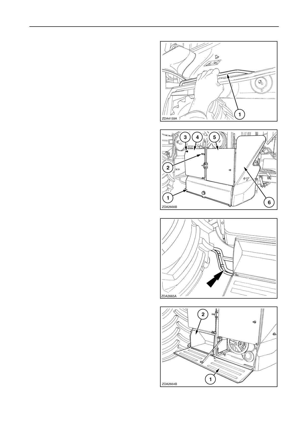
To open: Turn first the nut a quarter clockwise
with the special tool to unlock the shielding and
pull then the support (1) together wit the handle
to open the shielding completely.
NOTE: If not, using the support (1), the shielding can
not be opened completely.
30
1-37
SECTION 1 - GENERAL INFORMATION AND SAFETY
To close: Pull the support (1) together with the
handle to close the shielding.
31
10. Service platform (1) (left-hand side).
Pulling down the lever (2) will cause to open this
platform (1).
11. Service shielding (4). To open turn the lock (3).
12. Service shielding (5). To open the shielding (5),
open first service platform (1).
13. Rear service shielding (6). Open first the service
platform (1) and the service shielding (5).
32
14. Service step (left-hand side).
Use this step to check the concave or grain pan.
33
15. Toolbox.
Open the service platform (1) to gain access to
the toolbox (2) and use it as a step to service the
left-hand side of the combine.
(this shielding is foreseen to be locked).
34
1-38
SECTION 1 - GENERAL INFORMATION AND SAFETY
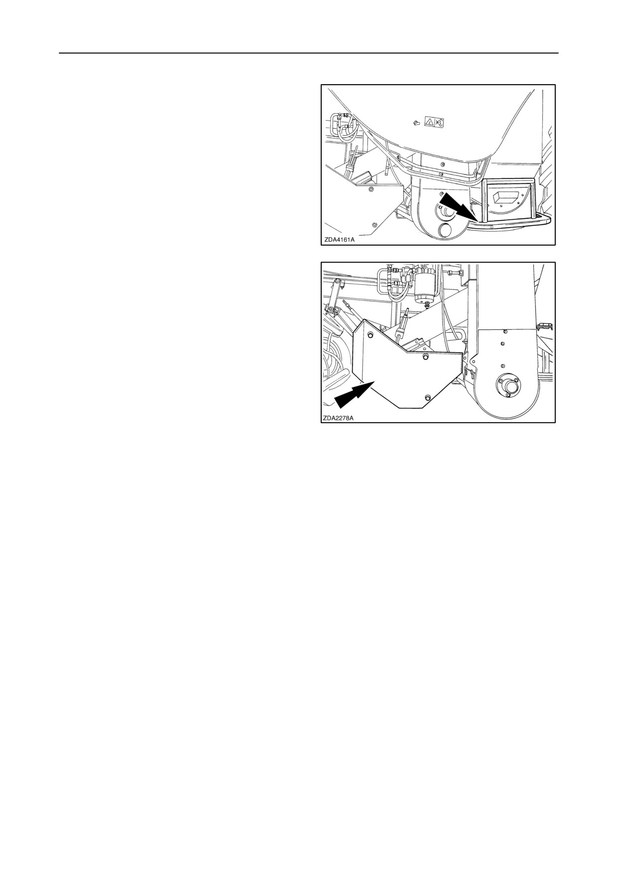
16. Service step (right-hand side)
Use this step to check the concave or grain pan.
35
17. Access cover to return auger drive
(right-hand side)
36
1-39
SECTION 1 - GENERAL INFORMATION AND SAFETY
PROTECTIVE DEVICES
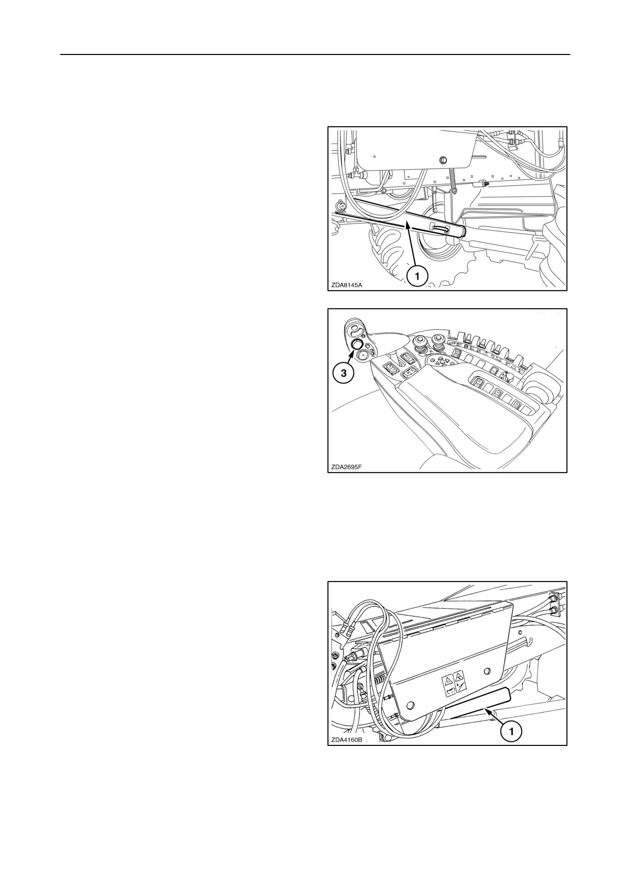
Header standard safety latch
The left-hand cylinder is standard fitted with a safety
latch which must be lowered onto the cylinder rod to
prevent accidental lowering of the header.
Whenever work is carried out underneath the header,
the latch must be lowered onto the cylinder rod as
shown at (1).
37
To engage or disengage the header safety latch is it
necessary to lift the straw elevator to its maximum
height.
To do this job, proceed as follows:
1. Select field mode using the field/road mode
selector switch.
2. Move the straw elevator up by pressing on the top
of the header height rocker switch (3) on the
multifunction handle until the header stops near
its maximum height.
3. Release the switch and press again for a
minimum of 1.5 seconds. The header will now
38
move quickly until its maximum height.
4. Place the header safety latch over the cylinder
rod.
NOTE: Never use the header safety latch (1) as a
support for the header when travelling along public
roads otherwise damage may occur to the cylinder.
When not in use, the header safety latch (1) must be
stored as shown.
39
1-40
SECTION 1 - GENERAL INFORMATION AND SAFETY
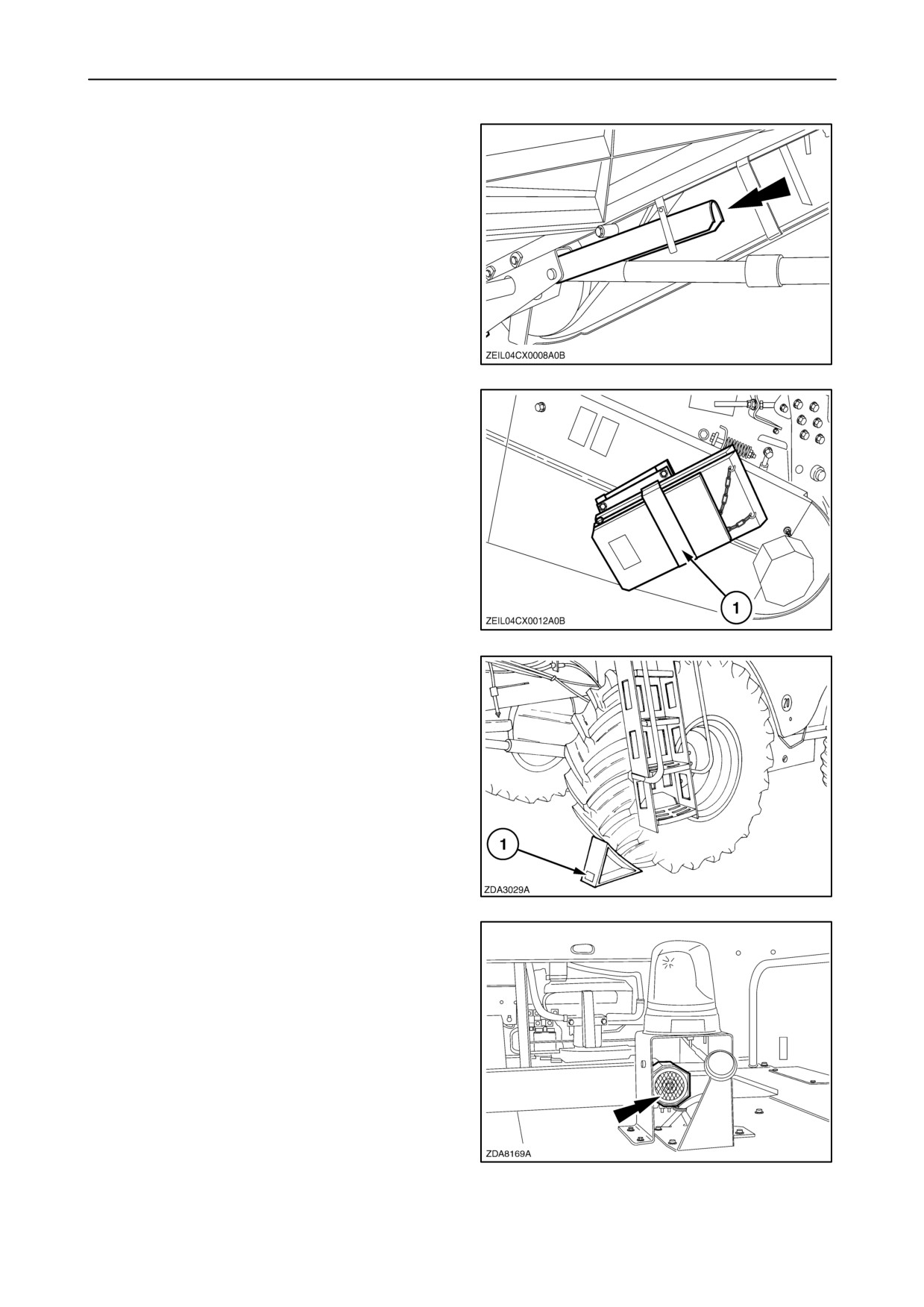
Extra safety latch
For some countries, a extra safety latch is installed
onto the right-hand side of the header lift cylinder.
40
Wheel chock
For some countries the metal wedges (1) are stored
at the right-hand side of the straw elevator.
41
When the machine is parked on a nonlevel surface,
the wedge (1) has to be placed at the lowest side,
against the traction wheel.
NOTE: Never place the wedges against the steering
wheels.
42
Buzzer (if installed)
On the top of the straw hood a buzzer is installed to
inform people that there will follow an action with the
combine. When the ignition key is put in “contact”
position the buzzer sounds once. When the combine
is placed in reverse, the buzzer sounds intermittently.
NOTE: The revolving flash lights (if installed) will also
flash for 2.5 seconds when the ignition key is put in
“contact” position.
43
1-41
SECTION 1 - GENERAL INFORMATION AND SAFETY
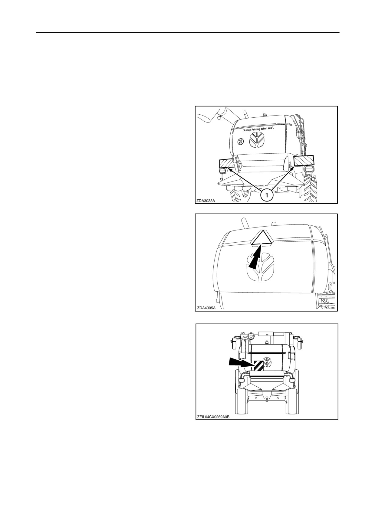
Safety railing for straw elevator
For some countries a safety railing must be installed
for road transport and secured to the front of the straw
elevator.
Signal plates
For some countries, the signal plates (1) must be
installed for road transport.
44
For some countries, a special signal plate
“slow moving vehicles” must be installed.
45
Signal plates for Italy
An additional support can be foreseen on the straw
hood to install a signal plate.
46
1-42
SECTION 1 - GENERAL INFORMATION AND SAFETY
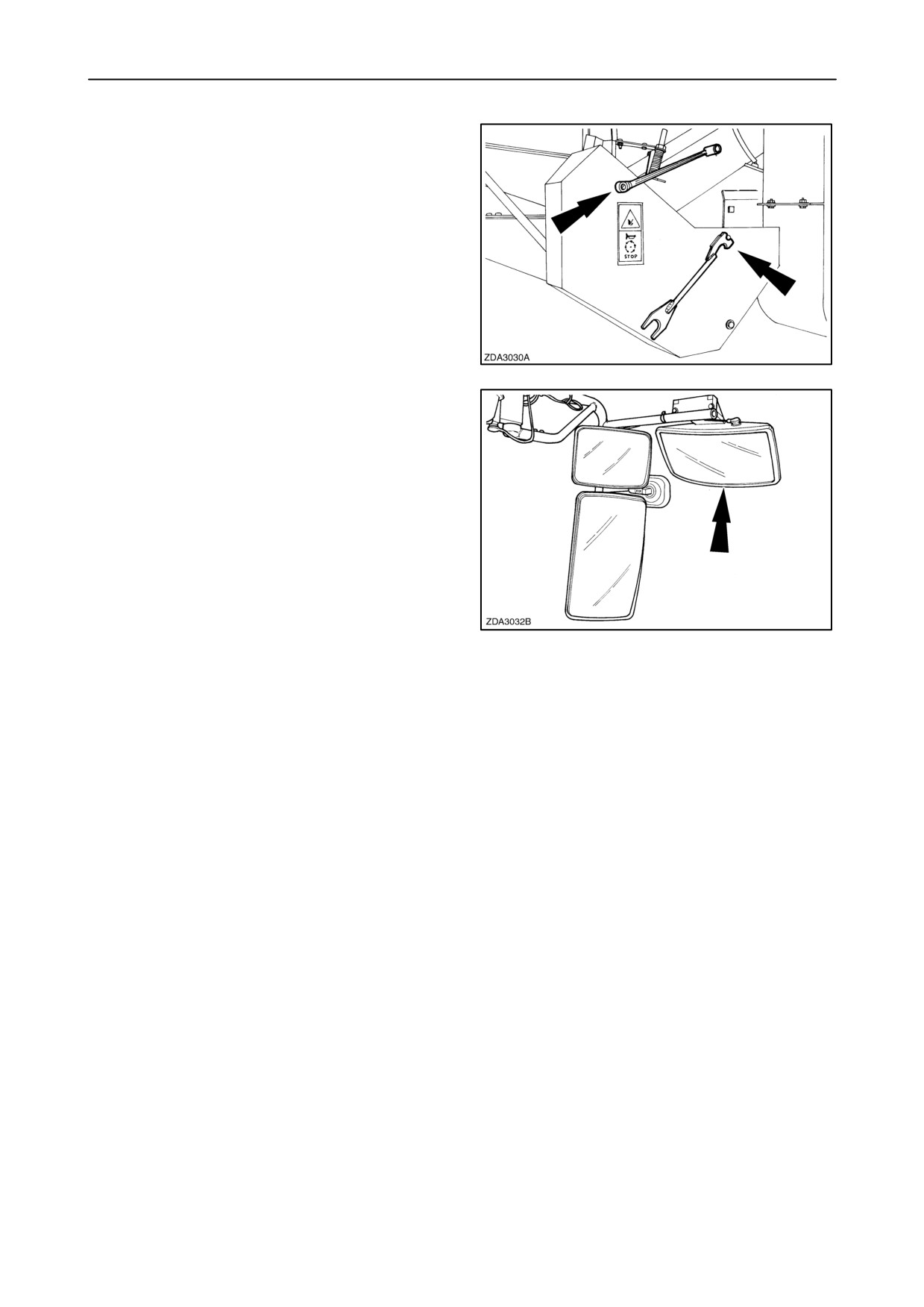
Safety guards
For safety’s sake and according to European
directives, safety guards now have locking devices
which can only be opened by means of the special
tool located on the left-hand side of the straw
elevator, a wrench (key width 13 mm) or a screw
driver.
47
Additional mirror for Germany
An additional mirror is required for Germany.
48
1-43
SECTION 1 - GENERAL INFORMATION AND SAFETY
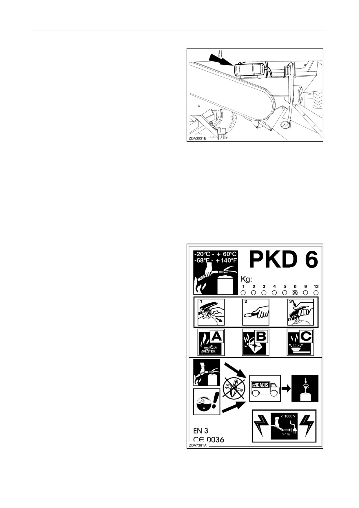
Fire extinguisher (with chopper drive)
The fire extinguisher is located on the left-hand side
near the straw hood.
Check the extinguisher pressure at least once a year
before the start of the season.
To check if the extinguisher is still under pressure,
proceed as follows:
1. Unscrew the pressure gauge from the valve.
49
2. The needle will go from the green area to ”0” in the
red area.
3. Rescrew the pressure gauge on the valve. The
needle will go from ”0” in the red field to the green
field.
If the needle remains in the ”0” of the red field, the
extinguisher has a leakage. The extinguisher has to
be repaired by a recognised extinguisher dealer.
Once the extinguisher is discharged, no matter for
how long, it must be recharged.
The decal on the fire extinguisher is explained below:
• The extinguisher can be used and has been
tested at temperatures of -20° C (-68° F) and
+60° C (+140° F).
• The type of the extinguisher “PKD 6”, this means:
Dry chemical powder and the capacity is 6 kg
(13.2 lbs).
1. Remove the safety pin.
2. Aim nozzle at base of fire.
3. Press on the handle.
The extinguisher can be used on
“A” class fires = dry fires
“B” class fires = liquid fires
“C” class fires = gas fires
• After use of the extinguisher on a fire, the
pressure gauge needle will go to zero pressure.
• Never try to repair or refill the extinguisher
yourself. Bring the used or leaking extinguisher to
a recognised extinguisher dealer.
• Never use the extinguisher on objects under
electrical tension of more than 1000 Volt and at
less than one meter (3,3 ft) distance.
50
1-44
SECTION 1 - GENERAL INFORMATION AND SAFETY
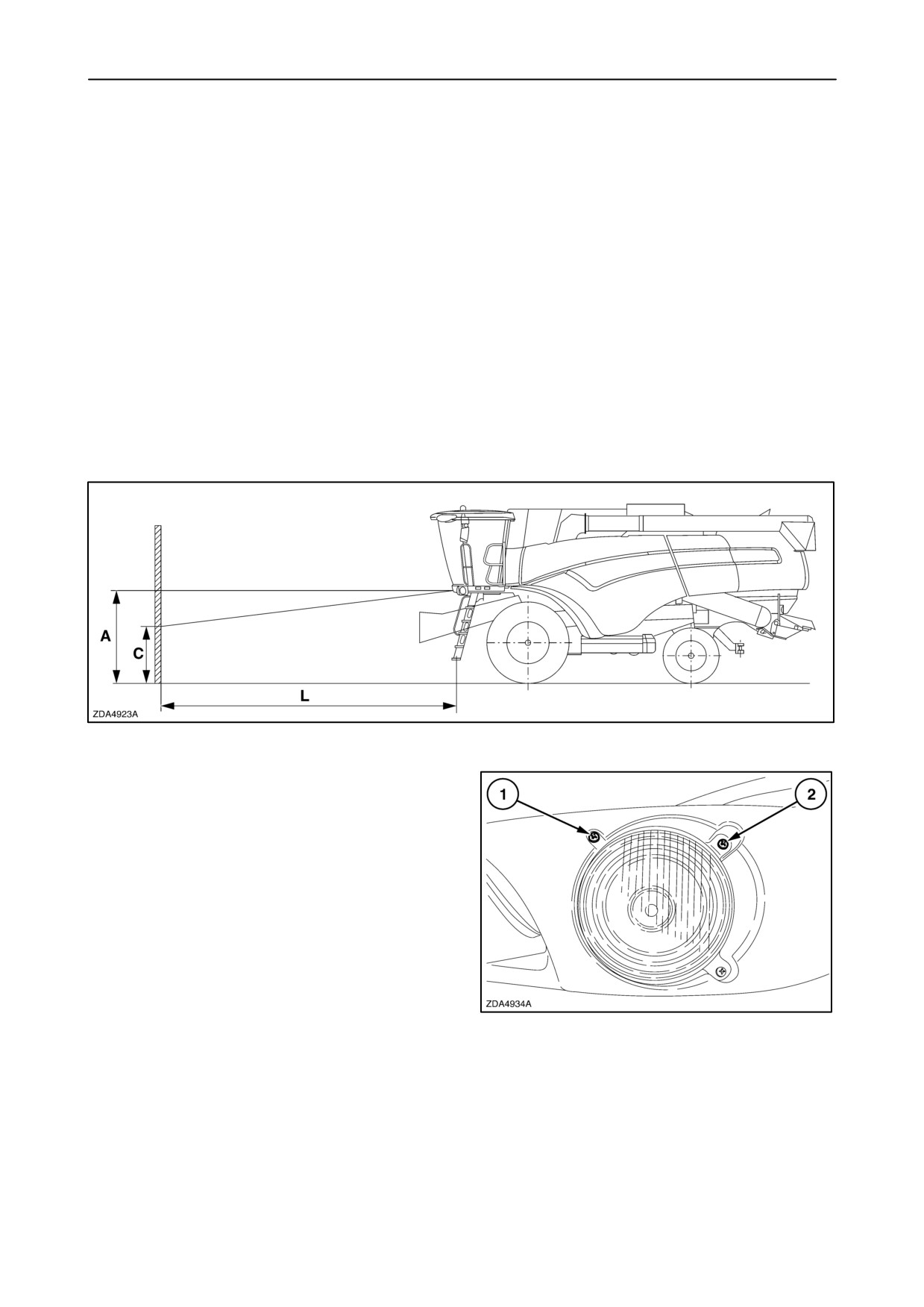
ADJUSTMENT OF THE DIMMED LIGHTS
The dimmed lights are “factory adjusted” with a level
standing combine.
However to adjust the dimmed lights, proceed as
follows:
1. Park the combine on a perfect level surface and
about 5 meter (16 ft) from a perpendicular square
dark wall.
2. Lower the straw elevator.
3. Measure distance A.
(A=distance from the
ground to the centre of the lamp)
4. Measure distance L. (L= distance from the light to
the wall)
5. Distance C should be maximum = A - (L x 0.07)
51
6. Adjust distance C, using screws 1 and 2.
NOTE: Turn screws 1 and 2 equally from both
dimmed lights.
52
1-45
SECTION 1 - GENERAL INFORMATION AND SAFETY
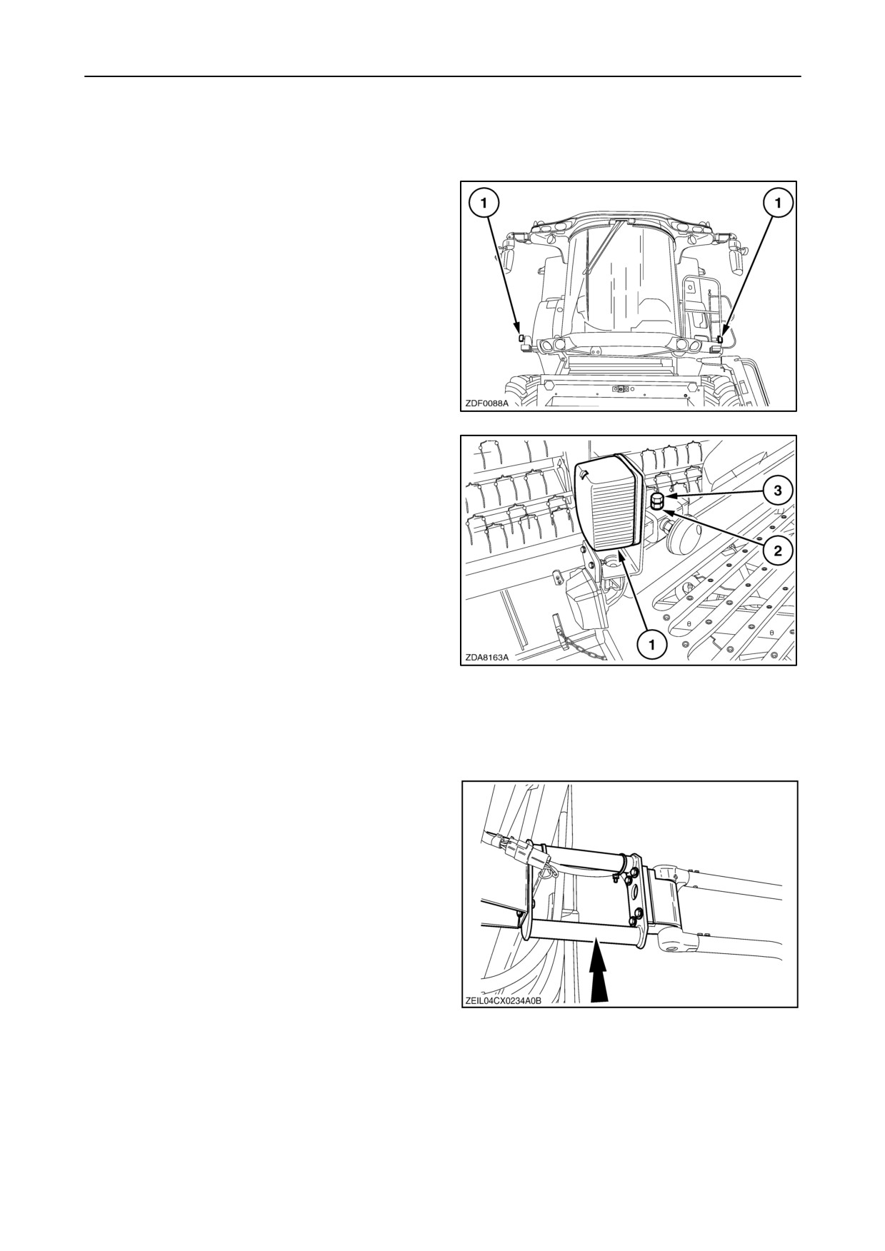
ADJUSTMENT OF THE SIDE LIGHTS
(IF INSTALLED)
The side lights (1) has to be adjusted to the maximum
width of the combine for road transport.
53
At the front:
To adjust, proceed as follows:
1. Loosen the nut (2) and the bolts (3) on both sides.
2. Slide the support with the side light (1) in or out
and adjust it to +/- 150 mm (5 - 29/32”) less than
the maximum width of the traction tyres.
3. After adjusting, tighten the bolts (3) and the nuts
(2) on both sides.
54
NOTE: Be sure that the side lights are installed
symmetric in relation to the middle of the combine.
At the rear:
A kit is available to install extensions to the rear light
arms, if required.
55
1-46
SECTION 1 - GENERAL INFORMATION AND SAFETY
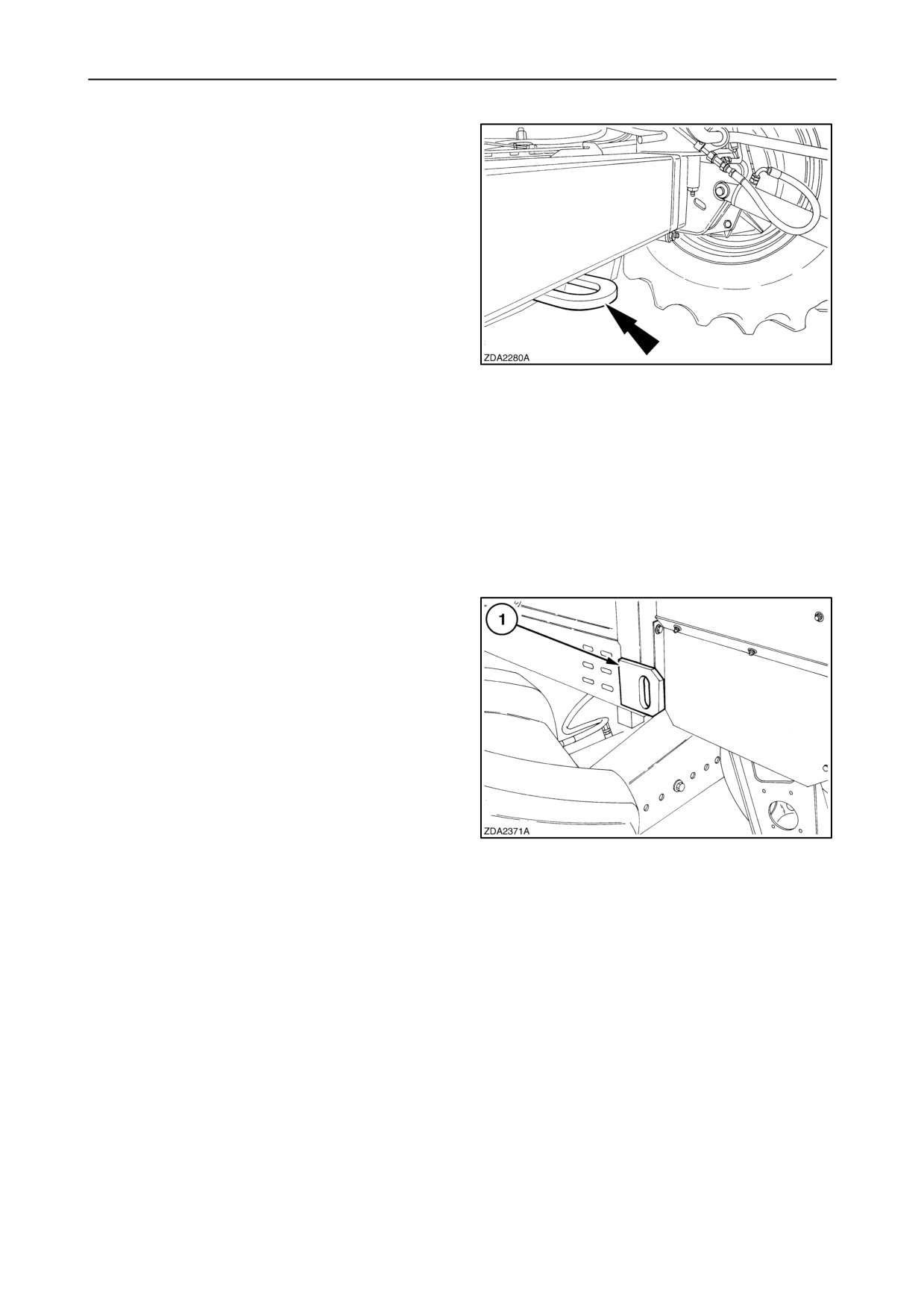
TOWING THE COMBINE
Towing the combine is not recommended, but if it
must be towed, the following steps must be taken:
1. Move the multi-function handle into neutral and
switch off the rear-wheel drive.
2. Select neutral gear. If not possible with the
remote gearshifting, refer to
Section 5 - ”FAULT FINDING”.
3. Release the handbrake. If not possible with the
remote parking brake switch, refer to
Section 5 - ”FAULT FINDING”.
4. Tow at a maximum speed of 16 km/h (10 MPH).
56
5. Provide adequate warning signals to make other
road users aware that the combine is being
towed.
NOTE:
1. Towing the combine with selected gear will
immediately lead to irreparable hydrostatic
damage.
2. Should the combine become stuck in the mud,
always tow the combine with a cable or chain
attached to the traction axle or at the rear to the
lower frame hooks (1). Never tow the combine
with a cable attached to the steering axle.
57
1-47
SECTION 1 - GENERAL INFORMATION AND SAFETY
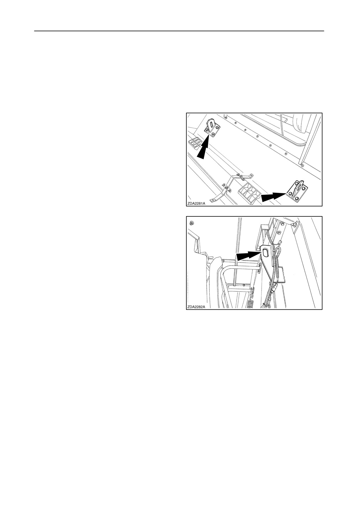
LIFTING THE COMBINE
To lift the combine (for example to park the combine
on a trailer for road transport) there are lifting hooks:
• At the front
Two lifting hooks are located in the grain tank.
NOTE: If the grain tank is equipped with grain tank
extensions, it will be necessary to do this job with
open grain tank extensions and open upper grain tank
covers.
58
• At the rear
Two lifting hooks are located at the left and right-hand
side on the top of the upper frame of the straw walker
section.
NOTE: Use long ropes or cables to lift the combine,
to avoid damage to the combine.
59
1-48
SECTION 1 - GENERAL INFORMATION AND SAFETY
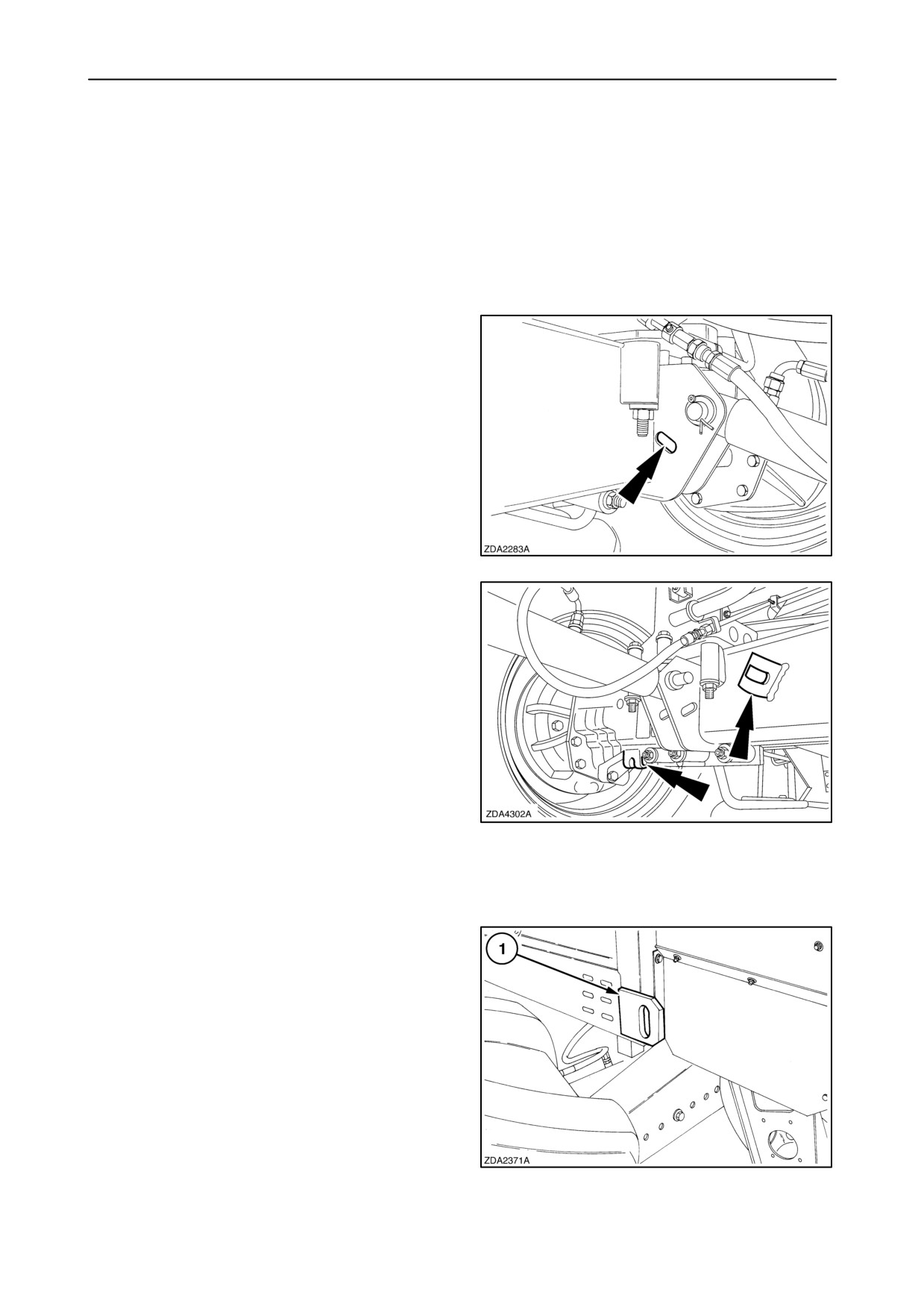
TIE DOWNS FOR SHIPPING
To hook-up the combine (e.g. trailer) proceed as
follows:
Install the combine on a trailer and support the front
and rear axle with wooden blocks as wide and as low
as possible.
• At the front:
There are two holes foreseen at the left-hand and
right-hand straw elevator lift cylinder support.
Hook-up with a rope or a chain in cross-bond.
60
Extra hooks are foreseen (if installed).
61
• At the rear:
Use hooks (1) to tie down the combine.
62
1-49
SECTION 1 - GENERAL INFORMATION AND SAFETY
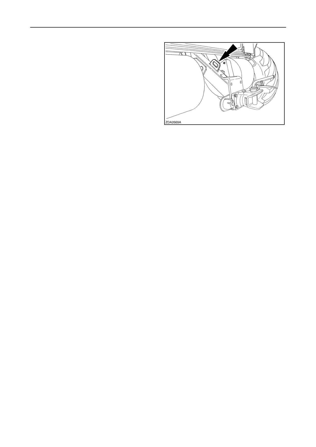
ATTACHING A TRAILER
A hook is foreseen on the top of the trailer hitch
support to pull a trailer with a cable to the combine to
attach.
63
1-50

SECTION 1 - GENERAL INFORMATION AND SAFETY
ATTACHMENT COMPATIBILITY
European models
Headers
CX720
CX740
CX760
CX780
CX820
CX840
CX860
CX880
High-Capacity Grain Header
13 ft
X
X
X
15 ft
X
X
X
X
17 ft
X
X
X
X
X
X
X
X
20 ft
X
X
X
X
X
X
X
X
24 ft
X
X
X
X
X
30 ft
X
X
X
X
Extra-Capacity + Varifeedt
Grain Header
20 ft
X
X
X
X
X
X
X
X
24 ft
X
X
X
X
X
30 ft
X
X
X
X
Maize header
MR570N
X
X
X
X
MR575W
X
X
X
X
MR580W
X
X
X
X
MR670N
X
X
X
X
X
X
X
X
MR675N
X
X
X
X
X
X
X
X
MR675W
X
X
X
X
X
X
X
X
MR680W
X
X
X
X
X
X
X
X
MF670N
X
X
X
X
X
X
X
X
MF675N
X
X
X
X
X
X
X
X
MF675W
X
X
X
X
X
X
X
X
MF680W
X
X
X
X
X
X
X
X
MF875W
X
X
X
X
X
MF880W
X
X
X
X
X
Flex header
19 ft
X
X
X
X
X
X
X
X
25 ft
X
X
X
X
X
1-51
SECTION 1 - GENERAL INFORMATION AND SAFETY
This is the logic of the maize header models:
Position 1:
M
Maize header
Position 2:
R or F
Rigid or Flip-up
Position 3:
5, 6 or 8
Number of rows
Position 4 and 5:
70, 75 or 80
Row distance
Position 6:
W or N
Wide or Narrow frame
Remarks:13 ft: Not recommended with blocked lateral flotation.
CAUTION
Before driving on the road with a header attached
smaller than 4 meter (foldable grain header or flip-up
maize header), the following actions must be done:
Contact your local dealer.
• Counterweights
• Additional headligths
• Brake force limiter valve
1-52

SECTION 1 - GENERAL INFORMATION AND SAFETY
Australian models
Headers
CX780
CX860
CX880
Grain header (72C rigid)
25 ft
X
NR
NA
30 ft
X
X
NR
Flex header (74C)
25 ft
X
NR
NA
30 ft
X
X
NR
Maize header (98C)
6-row (narrow)
X
X
NR
6-row (wide)
X
X
NR
8-row (narrow)
X
X
X
8-row (wide)
X
X
X
Windrow pick-up (76C)
14 ft
X
X
X
Grain draper (94C)
25 ft
X
NR
NA
30 ft
X
X
NR
36 ft
NR
X
X
39 ft
NA
X
X
Rice draper (92C)
21 ft
X
NR
NA
25 ft
X
X
NA
Flex draper (84C) (available 2003)
30 ft
X
X
NR
36 ft
NR
X
X
NR = Not Recommended
NA = Not Applicable
1-53
SECTION 1 - GENERAL INFORMATION AND SAFETY
1-54
SECTION 2 - CONTROLS, INSTRUMENTS AND OPERATION
SECTION 2 - CONTROLS, INSTRUMENTS AND OPERATION
CAB AND CONTROLS
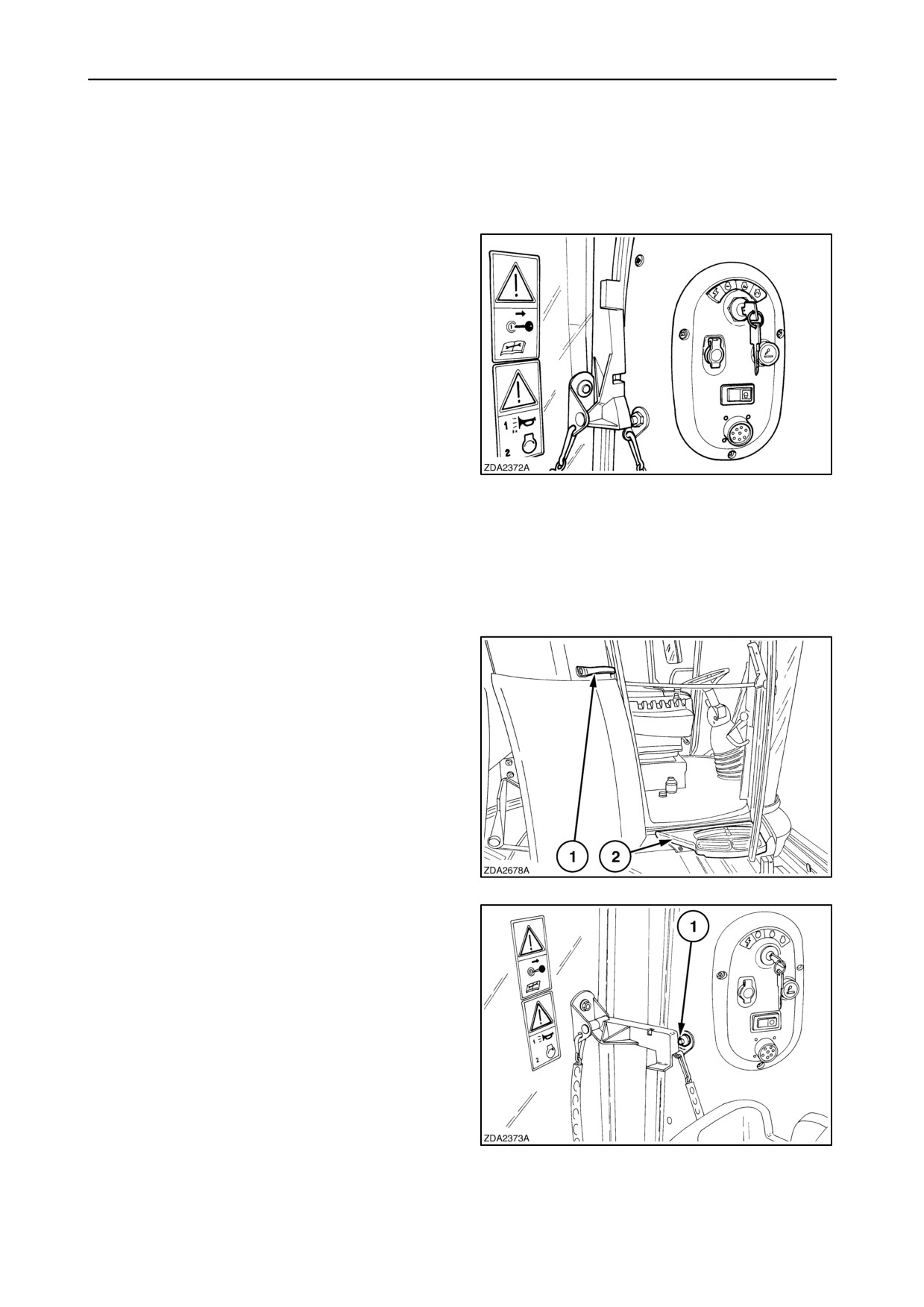
Emergency exit
The emergency exit is to be found on the right-hand
side of the operator’s seat, opposite to the door that
gives access to the cab.
To escape from the cab through the emergency exit,
proceed ad follows:
• Unlock the emergency exit door handle in three
steps.
1. Flip down the handle until it is in horizontal
position.
1
2. Push the door slightly open until the metal pin
that is attached to the cab frame is visible
through the notch in the handle.
3. Flip up the handle in order to release the
handle from the pin.
• Open the emergency exit door completely.
(is secured with a chain)
• Step over the right-hand module and leave the
cab.
• Use the handgrip (1) as handholds, the step (2)
and the traction tyre to step on.
2
An additional notch (1) is foreseen in the emergency
exit door handle to set the door in a fixed open
position.
3
2-1
SECTION 2 - CONTROLS, INSTRUMENTS AND OPERATION
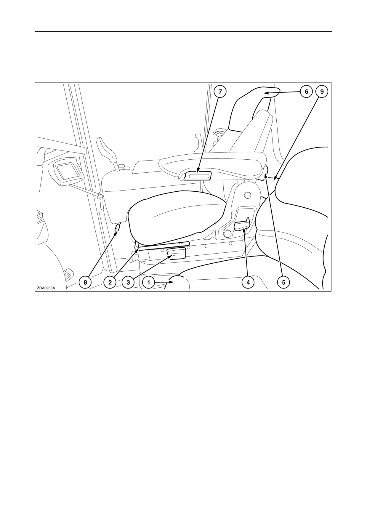
Operator’s seat and Surroundings
Air-suspended seat
4
1. Instructional seat, with seat belt (if installed).
2. Operator seat fore and after adjustment.
3. Weight and seat height adjustment. (air suspension)
Lift the lever briefly and the seat will automatically be
adjusted to the operator’s weight. (hold the lever to
override the automatic mode)
Moving the lever up and down will adjust the height of
the seat until the lever is released.
4. Seat back rest inclination adjustment.
5. Lumbar adjustment.
6. Seat upper back height adjustment.
7. Arm rest adjustment. (left-hand side)
8. Right-hand module fore and after adjustment.
9. Cover of storage box behind the seat.
2-2
SECTION 2 - CONTROLS, INSTRUMENTS AND OPERATION
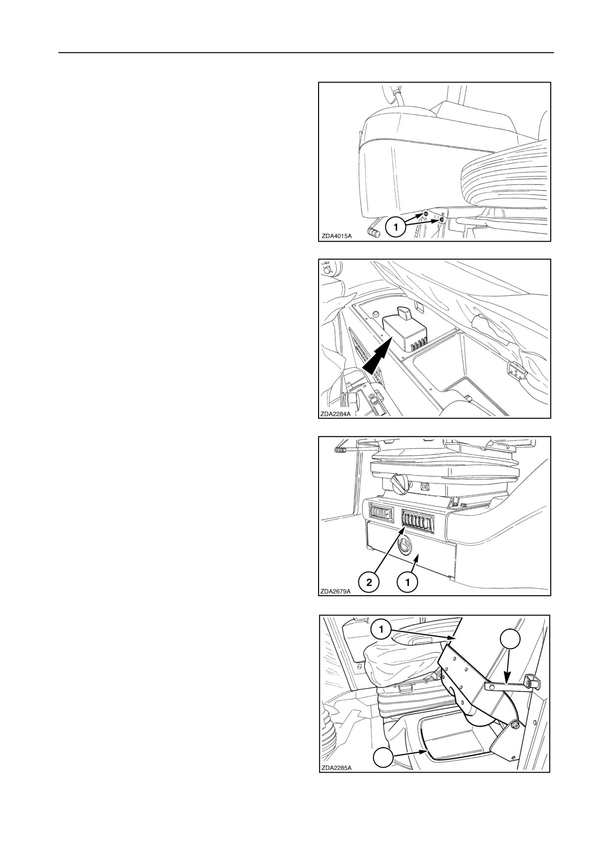
• The right-hand module can be vertical adjusted
by loosening the four bolts (1).
5
• The right-hand side of the storage box behind the
operator’s seat is foreseen with cold air
”cold box” (If installed).
6
• Storage drawer (1) located under the operator’s
seat.
• Adjustable air vents (2).
7
• Instructional seat (1). (If installed)
2
• The seat can be flipped-up and held in place by
strap 2, to give access to the storage place 3 for
small items.
3
8
2-3
SECTION 2 - CONTROLS, INSTRUMENTS AND OPERATION
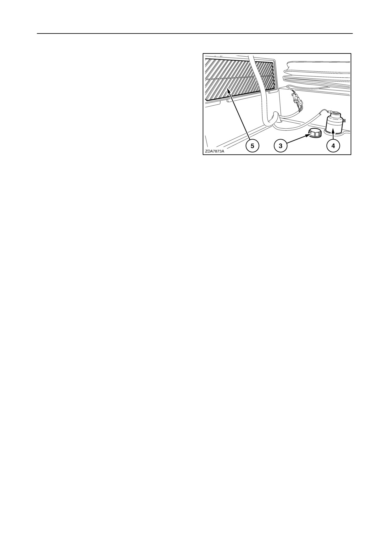
• Windshield washer reservoir (3). (if installed)
(Use windscreen washer
“TUTELA PROFESSIONAL SC 35”)
• Brake fluid reservoir (4).
• Recirculation filter (5).
9
2-4
SECTION 2 - CONTROLS, INSTRUMENTS AND OPERATION
Steering column and Control pedals
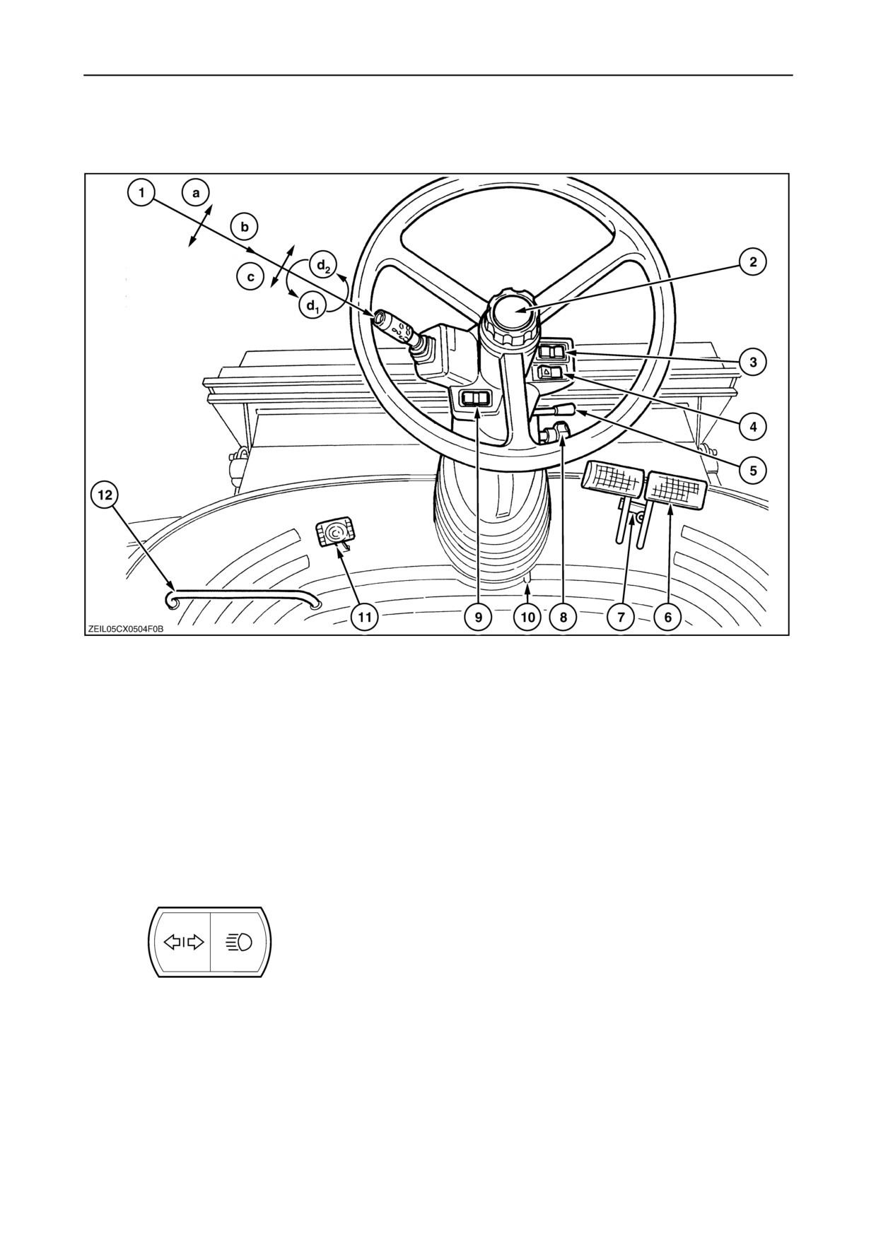
10
1. a. Direction indicator lever (left and right)
b. Horn (push)
c. Main beam headlights (up) and dipped headlights (down) selector switch
d. Parking lights (1 stop) and headlights (2 stop) turn switch
2. Steering wheel height control screw
Loosen this screw and lower or raise the steering wheel to the desired position.
3.
Right:
High beam headlight warning light
When the high beam headlight is switched ON, this light is illuminated.
Left:
Trailer direction indicator warning light (linked up with buzzer)
When a trailer is hooked up and the wires are properly connected, both DIREC-
TION INDICATOR WARNING LIGHT and TRAILER DIRECTION INDICATOR
WARNING LIGHT will flash.
2-5
SECTION 2 - CONTROLS, INSTRUMENTS AND OPERATION
4.
Hazard warning lights tumbler switch
When this switch is switched on, the four direction indicator lights on the corners
of the machine will start flashing and a buzzer will sound in the cab.
5. Steering wheel upper tilt control lever
Lift this lever and bring the steering wheel to a comfortable angle.
6. Foot brake pedal right
7. Brake pedal coupler
8. Foot brake pedal left
CAUTION
For safety reasons, always couple the brake pedals
by means of the brake pedal coupler when driving on
public roads. This ensures the brakes are actuated
together.
9.
Direction indicator warning lights, left and right
10. Steering column lower tilt control push pedal
Push this pedal and tilt the steering column to a comfortable angle.
11. Differential lock pedal (If installed).
12. Foot support. (if installed)
2-6
SECTION 2 - CONTROLS, INSTRUMENTS AND OPERATION
Right-hand module
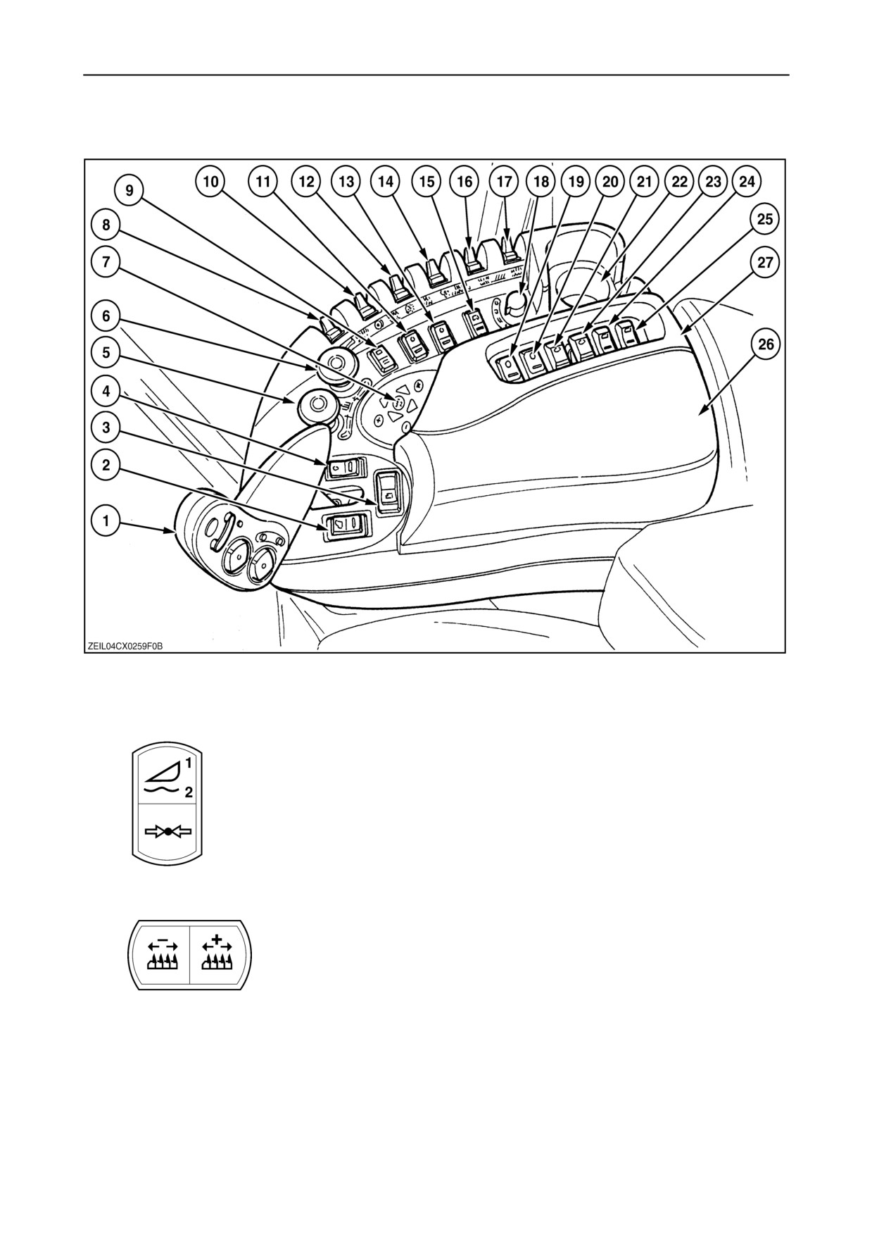
11
1. Multi function handle (see further in this section for more detailed information)
2.
Header memory switch
• Memorised header height 1
• Memorised header height 2
• Memorised header compensation
3.
Header width rocker switch
• Left-hand position: to decrease header width with one meter or one row unit,
when taking less than full width cut, to keep yield and mapping calculation
accurate.
• Right-hand position: to increase header width with one meter or one row
unit
2-7
SECTION 2 - CONTROLS, INSTRUMENTS AND OPERATION
4.
Engine throttle rocker switch.
• Increase engine speed
• Neutral
• Decrease engine speed
The engine rpm will automatically increase or decrease with one single pulse.
Press the opposite part of the switch to stop the automatic
(increase/decrease)engine rpm.
NOTE: The engine rpm can only be increased minimum 5 seconds after the
engine has been started.
5. Header/ Straw elevator engagement switch
• To engage, push down on the spring-loaded yellow cap and pull up the black ring under the yellow cap.
• To disengage, press on the top of the yellow cap.
6. Threshing mechanism engagement switch
• To engage, push down on the spring-loaded yellow cap and pull up the black ring under the yellow cap.
• To disengage, press on the top of the yellow cap.
When activating this switch, the engine rpm will automatically go to 1500 rpm +/- 50 rpm (CX860-CX880 = 1400 rpm)
(at any engine rpm) before engaging. (this may take a couple of seconds).
NOTE: The threshing mechanism can only be engaged if field mode (with the road-field mode tumbler switch, 15) is selected.
7. Control keypad with cursor keys and alpha-numeric keypad for the InfoViewt (see further in this section)
8. Not used
9.
Parking brake tumbler switch
• Parking position: When set in this position while driving, the parking brake
will be engaged after the multi function handle (hydrostatic) is set to neutral
position or if the ground speed is lower than 0.5 km/h (0.3 mph).
• OFF: When selecting another gear, the parking brake is activated.
NOTE: The parking brake will be ON each time the contact is put on. At least toggle the parking brake tumbler switch once
to release the parking brake in this case.
10. Drum speed rocker switch
Push the switch to increase the drum speed, pull to decrease (from the operator’s seat).
When touching this switch, the drum speed rpm is shown on a ”pop-up” screen of the InfoViewt monitor.
2-8
SECTION 2 - CONTROLS, INSTRUMENTS AND OPERATION
11.
Four wheel drive engagement tumbler switch (optional)
• ON
• OFF
If tracks are installed: four wheel drive in all the gears.
(If field or road mode selected)
If tracks are not installed: four wheel drive only in the first, second and third gear.
(If field mode selected)
12. Cleaning fan speed rocker switch
Push the switch to increase the fan speed, pull to decrease (from the operator’s seat).
When touching this switch, the fan speed rpm is shown on a ”pop-up” screen on the InfoViewt monitor.
13.
Powered Rear Axle dual speed tumbler switch (optional)
• High speed (Only if four wheel drive tumbler switch is engaged)
(Increasing of the speed by approximately 35%)
• Low speed
14. Drum concave clearance control rocker switch
Push the switch to increase the concave clearance, pull to decrease (from the operator’s seat).
When touching this switch, the drum concave clearance is shown on a ”pop-up” screen on the InfoViewt monitor.
15.
Road - Field mode tumbler switch
• Road mode
• Field mode
The following main functions will be disabled in road mode:
• Auto header height control + reel speed
• Header up/down (depend the header height position)+ lateral tilt, reel adjust
• Thresher, straw elevator engage, + Automatic Crop Settings adjust
• Unload tube open + unload engage
• Grain tank covers open
• Side and rear operating lights
2-9