New Holland CX720, CX740, CX760, CX780, CX820, CX840, CX860, CX880. Operator's Manual - page 1

CX720 CX820
CX740 CX840
CX760 CX860
CX780 CX880
OPERATOR’S MANUAL
Volume 1/2 - Operation
GENERAL
This manual has been prepared to assist you in the correct procedure for running in, driving, operating, adjusting
and maintaining your new machine.
This machine has been designed and built to give maximum performance, economy and ease of operation under
a wide variety of crops and conditions.
Prior to delivery, your machine was carefully inspected both at the factory and by your dealer to ensure that it
reaches you in optimum condition. To maintain this condition and ensure trouble-free operation it is important
that routine services, as specified in this manual, are carried out at the recommended intervals.
Before attempting to drive or operate your machine, read this manual carefully (especially the chapter covering
the Safety Precautions) and keep it in a convenient place for future reference.
’’Left” and ’’right” used throughout this manual are determined from the rear, facing in the direction of travel of
the machine during operation.
If at any time you require advice concerning your machine, do not hesitate to contact your authorised dealer.
He has factory-trained personnel, genuine service parts and the necessary equipment to carry out your service
requirements.
IMPORTANT:
This machine has been designed and built according to the European Directive 98/37/EC.
Always use genuine New Holland Service parts or parts matching at least the same quality, reliability and
functionality as the equivalent original Service Parts when servicing and repairing your machine and do not
modify your machine without a written permission of the manufacturer. Failure to do so will void the responsibility
of the manufacturer.
An EC Declaration of Confirmity is separately delivered with your machine.
Store this EC Declaration into the storage space for your Operator’s Manual
(refer to section 2 - Controls, Instruments and Operation).
The maximum road speed of your machine is limited electronically. Do not try to change it.
Check local road legislation before driving the machine on public roads.
When operating interchangeable New Holland built equipment, ensure the equipment is CE approved.
As this publication is distributed throughout our international network, the equipment illustrated, either as
standard or as an accessory, may vary according to the country in which the equipment is to be used. Low cost
configurations, as chosen by the customer, may deviate from the specifications given.
Several figures in this manual show the safety guarding or the additional guards, legally required by certain
countries, open or removed to illustrate better a particular feature or adjustment. The machine must not be used
in this condition. For your own safety, ensure that all guards are closed or replaced before operating the machine.
OWNER ASSISTANCE
We at New Holland and your New Holland dealer want you to be completely satisfied with your investment.
Normally your dealer’s Service Department will handle any problems with your equipment. Sometimes, however,
misunderstanding can occur. If your problem has not been handled to your satisfaction, we suggest contacting
the owner or General Manager of the dealership, explaining the problem, and requesting assistance. When
additional assistance is needed, your dealer has direct access to our branch office.
COMPANY POLICY
Company policy, which is one of continuous improvement, reserves the right to make changes in design and
specification at any time without notice and without obligation to modify units previously built.
All data given in this book is subject to production variations. Dimensions and weights are approximate only and
the illustrations do not necessarily show the machine in standard condition. For exact information about any
particular machine please consult your Dealer.
ACCESSORIES AND OPTIONS
Your machine has been designed to operate in a wide variety of crops and conditions. Nevertheless additional
equipment may, in certain cases, be required to improve the machine performance. A list of this additional
equipment is given in the ’’Accessories” section in this manual.
PARTS AND ACCESSORIES
Genuine New Holland parts and accessories have been specifically designed for New Holland machines.
We would like to point out that ’’nongenuine” parts and accessories have not been examined and released by
New Holland. The installation and/or use of such products could have negative effects upon the design
characteristics of your machine and thereby affect its safety. New Holland is not liable for any damage caused
by the use of ’’nongenuine” parts and accessories.
Rely on your authorised dealer to supply you with genuine New Holland parts only. These parts are covered by
our warranty and will give you the best performance.
When ordering service parts, always quote the model and serial number, as well as the year of manufacture
printed on the manufacturer’s identification plate (refer to chapter General Information).
LUBRICANTS
Your dealer sells a selection of specially formulated lubricants based on own engineering specifications.
Recommended lubricants for your machine are listed on the inside back cover of this manual.
WARRANTY
Your machine is warranted according to legal rights in your country and the contractual agreement with the selling
dealer. No warranty shall, however, apply if the machine has not been used, adjusted and maintained according
to the instructions given in this Operator’s Manual.
It is prohibited to carry out any modifications to the machine unless specifically authorised, in writing, by a New
Holland representative.
CLEANING YOUR MACHINE
Your machine is a state-of-the-art machine with sophisticated, electronic controls. Even though every precaution
has been taken to safeguard electronic components and connections, the pressure generated by some pressure
washers is such that complete protection against water ingress cannot be guaranteed.
When using a high pressure washer, do not stand too close to the machine and avoid directing the jet at electronic
components, electrical connections, breathers, seals, filler caps, etc.
IMPORTANT ENVIRONMENTAL CONSIDERATIONS
Soil, air and water are vital factors of agriculture and of life in general. Where legislation does not yet rule the
treatment of some of the substances, which are required by advanced technology, common sense should govern
the use and the disposal of the products of a chemical and a petrochemical nature.
The following are recommendations, which may be of assistance:
Become acquainted with and respect the relative legislation applicable in your country.
Where no legislation exists, obtain information from suppliers of oils, fuels, antifreeze, cleaning agents, etc. for
their effect on man and nature and for safe ways of storage, usage and disposal. Agricultural consultants will,
in many cases, be able to help you as well.
HELPFUL HINTS
Avoid filling fuel tanks using jerrycans or inappropriate pressurized fuel delivery systems which may cause
considerable spillage.
In general, avoid skin contact with all oils, acids, solvents, etc. Most of them contain substances which can be
harmful to your health.
Use biodegradable oils for chain lubrication where oils cannot be recuperated. In many countries rapeseed oils
or other agro-based lubricants have become available.
Modern oils contain additives. Do not burn contaminated fuels and/or waste oils in ordinary heating systems.
Avoid spillage when draining off used engine coolant mixtures, engine, gearbox and hydraulic oils, brake fluids,
etc. Do not mix drained brake fluids, fuels or coolant mixtures with lubricants. Store them safely until they can
be disposed of in a proper way to comply with local legislation and available resources. They should not be
allowed to get into the soil but should be collected and disposed of safely.
Do not open the air-conditioning system yourself; it contains gases, which should not be released into the air.
Your dealer has a special extractor for this purpose and will have to do the recharging of the system anyway.
Repair any leaks or defects in the engine cooling or the hydraulic system immediately.
Do not increase the pressure in a pressurized circuit as this may lead to bursting of the components.
Protect hoses during welding as penetrating weld splatter may burn a hole or weaken them, causing the loss
of oils, coolant, etc.
Battery recycling
Batteries and electric accumulators contain various components which can damage the environment if they are
not properly recycled after usage. New Holland strongly recommends that you return all used batteries (starting
batteries and small ”dry” batteries which may be used in electric or electronic systems) to your New Holland
dealer who will ensure proper disposal or recycling. In certain countries this is a legal requirement.
e2005 CNH Belgium NV-Zedelgem
SECTION QUICK REFERENCE
1 - General Information and Safety
2 - Controls, Instruments and Operation
3 - Field and Site Operation
4 - Lubrication and Maintenance
5 - Fault Finding
6 - Vehicle Storage
7 - Accessories
8 - Specification
9 - 1st 50 Hour Service Sheets
Index
NOTE: The CX Operator’s manual consists of two volumes. The first volume “Operation“ with sections 1,2 and
3, the second volume “Maintenance” with sections 4,5,6,7,8 and 9.
TABLE OF CONTENTS
Title
Page
(Volume 1/2 - Operation)
SECTION 1 - GENERAL INFORMATION AND SAFETY
Intended use
1-1
Product identification
1-1
Base unit
1-1
Engine
1-2
Grain header (High-Capacity, Extra-Capacity or Varifeedt)
1-3
Maize header
1-3
Flex header
1-3
Maize header (98C)
1-4
Draper header (92C/94C)
1-4
Grain - Rice - Flex header (72C/74C)
1-4
Record below the serial numbers of your machine for quick reference:
1-5
General recommendations
1-6
Starting up the combine
1-8
Travelling on public roads
1-9
Operating the combine
1-10
Operating the attachments
1-11
Stopping the combine
1-11
Maintenance
1-11
Engine
1-13
Diesel fuel
1-14
Battery warning
1-15
Illustrations
1-15
Stability
1-16
Legal Obligations
1-16
Safety Requirements
1-16
Airborne Noise Emission
1-17
ElectroMagnetic Compatibility (EMC)
1-17
Vibration Level Information
1-17
Safety decals
1-18
Safety decals (Australia)
1-27
Access to machine components
1-34
Protective Devices
1-40
Header standard safety latch
1-40
Extra safety latch
1-41
Wheel chock
1-41
Buzzer (if installed)
1-41
Safety railing for straw elevator
1-42
Signal plates
1-42
Signal plates for Italy
1-42
Safety guards
1-43
Additional mirror for Germany
1-43
Fire extinguisher (with chopper drive)
1-44
Adjustment of the side lights
1-46
i
Towing the combine
1-47
Lifting the combine
1-48
Tie downs for shipping
1-49
Attaching a trailer
1-50
Attachment Compatibility
1-51
European models
1-51
Australian models
1-53
SECTION 2 - CONTROLS, INSTRUMENTS AND OPERATION
Cab and Controls
2-1
Emergency exit
2-1
Operator’s seat and Surroundings
2-2
Steering column and Control pedals
2-5
Right-hand module
2-7
Multi-Function Handle
2-12
Shaft Speed Monitor (SSM)
2-15
Start module
2-17
Cab roof controls
2-18
Climate control
2-23
1. Manual controller
2-24
2. Automatic Temperature Control (ATC)
2-25
Error table
2-27
Lighting and Mirrors
2-32
Other components
2-35
InfoViewt Monitor
2-38
InfoViewt Monitor
2-40
Menus and sub-menus
2-50
MDM Protected mode
2-52
I Road info screen
2-53
Elapsed time
2-54
Trip distance
2-54
Area harvested
2-54
II Main info screen
2-55
General
2-55
Sensitivity setting of straw walker and sieve loss sensor
2-56
Setting of the returns capacity
2-57
III Custom Info screen
2-58
IV Harvest Info screen
2-59
1. Instantaneous values
2-61
Instantaneous parameter list
2-62
2. Select active load
2-63
Select or create Farm, Field, or Load name
2-63
Farm name
2-63
Crop type
2-65
3. Harvest summary
2-66
Harvest summary parameter list
2-67
4. Marker setup
2-68
5. Calibration
2-71
Sensor selection
2-71
Crop calibration setup
2-72
Perform crop calibration
2-73
Data logger (if installed)
2-74
ii
Calibrations for yield Monitoring or Mapping
2-77
(Differential) Global Positioning System - (D)GPS (if installed)
2-78
V Automatic Crop Settings
2-83
General
2-83
Factory default values (Automatic Crop Settings)
2-84
Activating the ACS
2-85
Saving ACS user settings
2-86
Crop settings and current settings
2-86
Crop settings
2-86
ACS mode screen
2-89
Current settings
2-90
VI Combine info screen
2-91
VII Configurations and Calibrations
2-92
1. Road info screen setup
2-93
2. Main info screen setup
2-94
3. Custom info screen setup
2-95
Page Setup
2-96
4. Display settings
2-99
LCD contrast
2-100
LCD night brightness
2-100
Speaker volume
2-100
SSM lcd backlight
2-101
Language selection
2-101
Unit system
2-102
Error handling
2-102
5. Calibration
2-105
Calibrations for Basic operation
2-106
Calibration of the Header
2-107
Calibration of the Tyre radius (ground speed)
2-110
Calibration of the Multifunction handle
2-112
Calibration of the Concave position
2-114
Calibration of the Upper sieve
2-116
Calibration of the Lower sieve
2-117
Calibration of the Self-levelling cleaning shoe
2-118
Calibration of the Spreader plates
2-120
Calibration of the Maximum stubble height
2-121
Calibration of the Ground speed hydrostatic
2-122
Calibration of the Zero returns volume
2-125
Calibrations for SmartSteert system (If installed)
2-127
Calibration of the HGS Turntable actuator
2-128
Calibration of the HGS Turntable sensor
2-135
6. Combine
2-137
7. Engine
2-138
8. Electrical
2-139
9. Hydraulics
2-139
10. Driveline
2-140
11. Header
2-142
12. Straw elevator
2-154
13. Threshing
2-154
14. Cleaning
2-155
15. Clean grain/Unloading
2-157
16. Residue
2-158
17. Precision farming
2-159
VIII Diagnose info screen
2-161
iii
IX Service info screen
2-161
1. Active alarms
2-162
2. Active errors
2-163
3. Error history
2-164
4. Service
2-166
5. Network
2-168
Audible alarm
2-170
Automatic engine shut-off
2-170
SECTION 3 - FIELD AND SITE OPERATION
Before driving the combine
3-1
Starting the engine
3-2
Daily Start-up procedure
3-2
Stopping the engine
3-3
Driving the combine
3-3
Parking brake
3-4
Emergency stop (If configured in InfoViewt)
3-4
Gear shifting system
3-5
Differential lock (if equipped)
3-5
Harvesting
3-6
Description of operation
3-6
Crop settings
3-10
To change from grain to maize configuration, the following modifications has to be done.
3-14
Kill stall
3-16
Performance indicators
3-16
Grain tank sample
3-16
Grain pan/ upper sieve distribution
3-17
Returns sample
3-17
Losses
3-17
How to obtain an idea on loss level
3-19
Header
3-20
Attaching the header to the combine
3-20
Detaching the header from the combine
3-22
Header Height Controls
3-23
Flex header operation
3-27
Auto header lift
3-27
Reel to ground speed synchronization
3-28
SmartSteert System (if installed)
3-30
Feeding/Straw elevator
3-33
Lower shaft adjustment
3-33
Header and straw elevator reversing system
3-35
Intermediate plate
3-36
Straw elevator bottom plate (if installed)
3-37
Limitation of the lateral float system
3-37
Straw elevator - Removal and Installation
3-38
Removal
3-38
Installation
3-41
Stone trap
3-42
Threshing
3-43
Anti-dust plate
3-43
Drum and concave
3-43
Parameters
3-43
Fundamentals of Adjustments
3-43
iv
Drum speed
3-44
Drum blockage
3-44
Concave clearance
3-45
Drum and concave type of use
3-46
Replacement of the drum concave
3-46
Setting of different types of concaves
3-53
De-awning plates
3-54
Separation
3-55
Beater
3-55
Rotary separator
3-56
Multi-thresh system
3-57
Straw flow beater
3-57
Straw retarding curtain
3-58
Straw walkers
3-58
Cleaning system
3-59
Cleaning shoe
3-59
Removable grain pan (if installed)
3-59
Grain pan removal
3-59
Grain pan installation
3-61
Sieves
3-62
Sieve openings
3-62
Sieve position
3-64
Sieve removal
3-64
Sieve installation
3-67
Types of sieves available
3-69
Cleaning fan
3-70
Returns system
3-71
Grain storage/Unloading
3-73
Grain tank filling system
3-73
Grain sample access
3-77
Grain tank window
3-77
Grain tank with extensions
3-78
Grain tank with covers
3-78
Grain tank level sensor
3-79
Grain tank unloading auger
3-80
Unloading tube swing
3-81
Unloading mechanism
3-81
Straw handling
3-82
Straw chopper (if installed)
3-82
Engaging of the straw chopper
3-82
Chopping cereals
3-83
Chopping maize
3-84
Straw chopper spreader chute
3-86
Spread pattern
3-86
Remote controlled divider plates (if installed)
3-87
Rotor knives
3-87
Counter knives
3-88
Swath-forming position
3-88
Baffle plate
3-89
Chaff blower (if installed)
3-90
Chaff spreader (if installed)
3-92
Automatic rotation trailer hitch (If installed)
3-93
INDEX
v
(Volume 2/2 - Maintenance)
SECTION 4 - LUBRICATION AND MAINTENANCE
General
4-1
Grease fittings and intervals
4-1
Grease specification
4-1
Grease interval
4-3
10 hours interval
4-3
50 hours interval - left-hand side
4-3
100 hours interval - left-hand side
4-8
50 hours interval - right-hand side
4-8
100 hours interval - right-hand side
4-12
200 hours interval - left-hand side
4-12
Engine
4-14
Oil level
4-14
Oil and filter change intervals
4-15
Engine sump and filter capacity (total)
4-17
Oil specification
4-17
Crankcase breathing system (Iveco engine)
4-18
Crankcase breathing system (CNH engine)
4-19
Turbocharger compressor (CNH engine)
4-20
Aftercooler (CNH engine)
4-20
Engine cooling system
4-21
Coolant level
4-21
Coolant change
4-21
Coolant system capacity
4-23
Coolant specification
4-23
Fuel system
4-23
Fuel level
4-23
Filling the fuel tank
4-24
Fuel tank capacity
4-24
Fuel specification
4-25
Fuel storage
4-26
Fuel prefilter/water separator
4-26
Fuel filter (CNH engine)
4-27
Fuel supply pump
4-27
Bleeding the fuel system (CNH engine)
4-28
Fuel filter (Iveco engine)
4-29
Bleeding the fuel system (Iveco engine)
4-29
Rotary dust screen and Cooling system
4-30
Air intake system
4-31
Hydraulic and Hydrostatic system
4-33
Oil reservoir
4-33
Oil level
4-33
Oil and filter change
4-33
Oil capacity
4-36
Oil specification
4-36
Filter at oil cooler outlet
4-36
Engine gearbox
4-37
Oil level
4-37
Oil and filter change
4-37
Oil capacity
4-39
Oil specification
4-39
vi
Traction gearbox
4-40
Oil level
4-40
Oil change
4-40
Oil capacity
4-41
Oil specification
4-41
Final drive gearboxes
4-42
Oil level
4-42
Oil change
4-42
Oil capacity
4-43
Oil specification
4-43
Unloading drive gearbox
4-44
Oil change
4-44
Oil capacity
4-44
Oil specification
4-44
Unloading tube gearbox
4-45
Oil check
4-45
Oil capacity
4-45
Oil specification
4-45
Bubble-up gearbox
4-46
Oil change
4-46
Oil capacity
4-46
Oil specification
4-46
Chains, Threaded rods and Pivot points
4-47
Chains
4-47
Threaded rods
4-48
Pivot points
4-48
Brake system
4-49
Brake fluid level
4-49
Fluid change
4-49
Capacity
4-49
Fluid specification
4-49
Lubrication schedule
4-50
Belts and Chains
4-52
Checking and adjusting
4-62
Low speed fan variator kit (If installed)
4-63
Feeding
4-67
Straw elevator chain
4-67
Intermediate roll (if installed)
4-67
Slip clutch
4-67
Front Face Adjustment (if installed)
4-68
Threshing
4-69
Anti-dust plate
4-69
Cleaning
4-70
Sieves
4-70
Pivot axle (self levelling cleaning shoe)
4-70
Roto-threshers
4-71
Grain storage
4-72
Slip clutch
4-72
Moisture sensor (if installed)
4-72
Grain flow sensor (if installed)
4-76
vii
Brakes
4-79
Foot brakes
4-79
Parking brake
4-79
Fluid change
4-79
Hydraulic equipment
4-80
Tracks (If installed)
4-81
Steering axle
4-83
1. Steering axle position
4-84
2. Axial position of the steering axle
4-84
3. Steering axle height position
4-86
4. Track width position
4-87
5. Toe-in adjustment
4-104
6. Steering cylinder adjustment
4-106
Electrical system
4-107
Fuses and relays
4-107
Combine Control Module (CCM)
4-112
Batteries
4-113
Alternator
4-115
Cab/Climate control
4-116
Cab air filter
4-116
Air conditioning
4-117
Condenser
4-118
Fresh air intake grill
4-118
Recirculation filter
4-118
Filter-drier
4-119
Air compressor (if installed)
4-120
Air reservoir specification
4-121
SECTION 5 - FAULT FINDING
Feeding area
5-1
Threshing area
5-1
Threshing, Separation and Cleaning
5-3
General
5-7
Engine
5-8
Straw Chopper
5-9
Powered Rear Axle
5-10
Manual release of the hydraulic parking brake
5-11
Gearshifting
5-12
Hydraulic valve electrics
5-14
SECTION 6 - VEHICLE STORAGE
End-Of-Season Service
6-1
Ordering Parts and/or Accessories
6-2
Preseason Service
6-3
SECTION 7 - ACCESSORIES
Feeding
7-1
Side hill weights
7-1
Crop distribution kit
7-1
Hydraulic reel rebuild kit
7-1
Grain header road light kit
7-2
viii
Perforated straw elevator floor section
7-2
Straw elevator drive
7-2
Intermediate roll
7-2
Header lift cylinder kit
7-3
Narrowing plates
7-3
Potentiometer for flex header 19 ft
7-3
Threshing and Separation
7-4
De-awning slats
7-4
Rice pins
7-4
Tool to remove the concave
7-4
Vertical knife electricity kit
7-5
Sunflower cover plate
7-5
Beater pins
7-5
Beater blades
7-5
Beater wear plates
7-5
Vertical covers on straw walkers
7-6
Straw walker raisers
7-6
Cereals threshing rebuild kit
7-6
Maize threshing rebuild kit
7-7
Rice threshing rebuild kit (if universal drum)
7-7
Maize concave
7-7
Cleaning system and lower frame
7-8
Remote sieve control
7-8
Fan bottom shield
7-8
Grass seed variator kit
7-8
Presieve HC 1-5/8”
7-9
Grain pan divider kit
7-9
Round hole sieve frame
7-9
Round hole sieve (16 or 18 mm)
7-9
Adjustable chaffer 1-5/8” and 1-1/8”
7-10
Adjustable upper sieve (Petersen 1-1/8”)
7-10
Closz upper sieve
7-10
Stainless steel curved louver maize upper sieve
7-10
Graepel sieve extension
7-10
Extended sieve dividers
7-11
Smooth rotor thresher covers
7-11
Clean grain, Grain tank and Unloading
7-12
Unloading tube extension kit
7-12
Perforated covers: Long or Round
7-12
Straw handling
7-13
Chaff blower
7-13
Chaff spreader
7-13
Straw chopper
7-14
Remote deflectors control
7-14
Straw chopper kit for maize
7-14
Straw chopper wind knife kit
7-14
Traction and tyres
7-15
Powered Rear Axle (wheel motors)
7-15
Dual speed (Powered Rear Axle II)
7-15
Axle extensions kit
7-15
Pivot plate 127 mm
7-16
Wheel spacer
7-16
Steering platform extensions
7-16
Tracks
7-16
ix
Foldable ladder
7-16
Engine
7-17
Air compressor kit
7-17
Coolant heater
7-17
Rotary dust screen brush
7-17
Fuel cooler
7-17
High fan speed kit
7-17
Cab
7-18
Windscreen washer system
7-18
In cab printer
7-18
Cab heating
7-18
Premium speakers
7-18
Electrical and Electronic
7-19
Flip-up light kit
7-19
Rear revolving flash light
7-19
Revolving flash lights
7-19
Portable work light
7-20
Light extension kit
7-20
Electronic module (CCM3)
7-20
Yield monitoring package
7-21
Yield mapping package
7-22
Yield logging package
7-23
SmartSteert system
7-23
Miscellaneous
7-24
Header trailer hitch
7-24
Counterweights support frame
7-25
Frame counterweights
7-25
Wheel counterweights
7-25
Signal plates
7-25
Signal plates for Italy
7-26
Unload tube signal plate+light
7-26
Fire extinguisher
7-26
Wide fender
7-26
SECTION 8 - SPECIFICATIONS
Wheels and tyres
8-1
Wheel nuts torque
8-1
Technical data
8-30
Dimensions
8-40
Dimension I (3)
8-42
Dimension J (3)
8-43
Dimension K (4)
8-43
Counterweights
8-44
SECTION 9 - 1ST 50 HOUR SERVICE SHEETS
Check and Adjust, as required (Customer copy)
9-1
Check and Adjust, as required (Dealer copy)
9-3
INDEX
x
SECTION 1 - GENERAL INFORMATION AND SAFETY
SECTION 1 - GENERAL INFORMATION AND SAFETY
INTENDED USE
The CX combine harvesters are designed as self
propelled units and powered by an onboard diesel
engine.
The machines are intended to be used for agricultural
purposes on cultivated land to harvest cereal crops,
small seed crops, maize, soy beans, etc., by cutting
or picking up from a swath, threshing and separating
the grain from the straw and temporarily storing it until
it is unloaded into vehicles for transport.
PROHIBITED USAGE
No parts or attachments should be fitted to this
machine, which have not been released by NEW
HOLLAND. They might affect machine operation,
safety of the user or other people, stability or wear
characteristics of the machine. They may also void
the homologation approval obtained for your country.
PRODUCT IDENTIFICATION
The serial number of the combine, the engine and the
attachments can be found on the following locations:
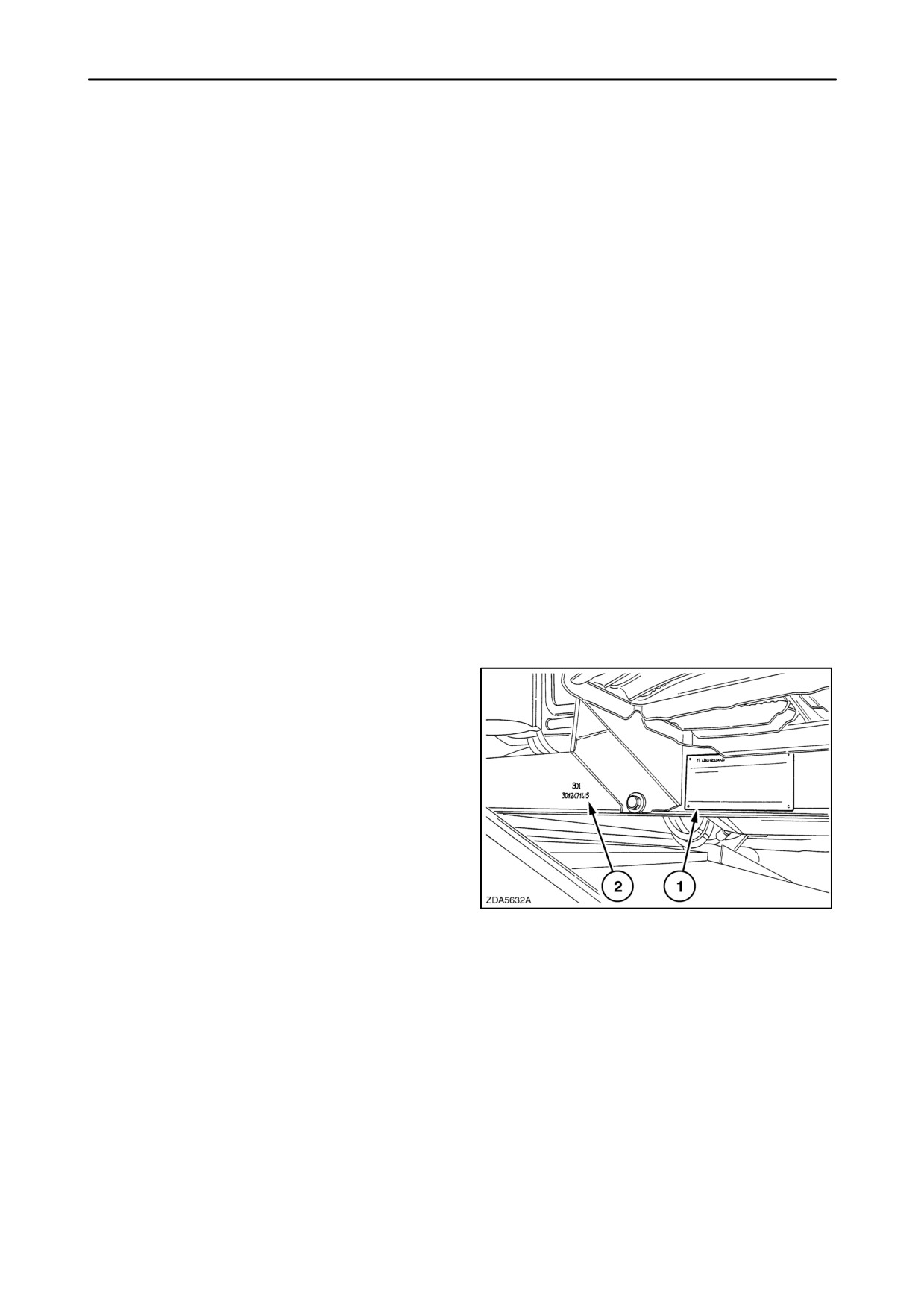
Base unit
On a plate (1) positioned on the right-hand side of the
operator’s platform and it’s also stamped at (2).
1
1-1
SECTION 1 - GENERAL INFORMATION AND SAFETY
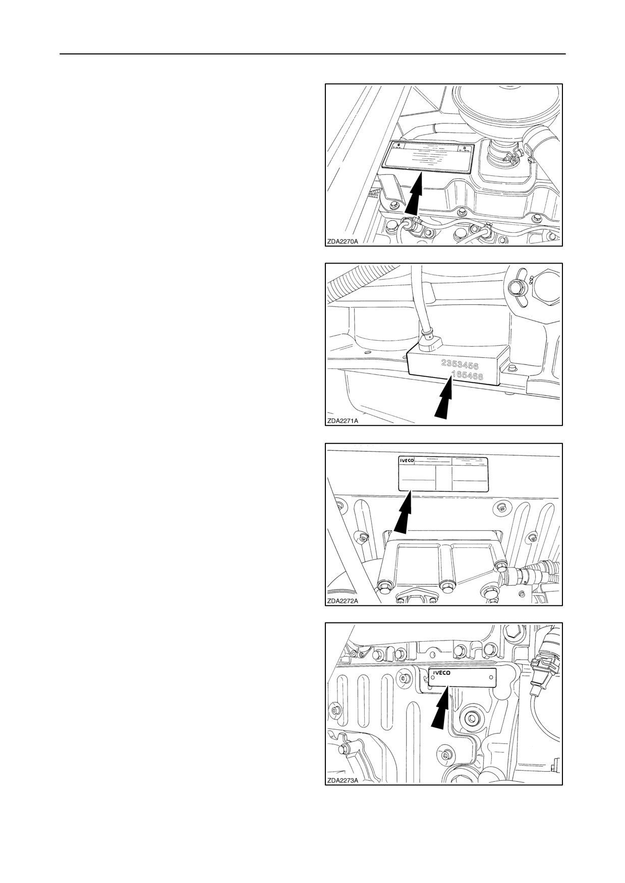
Engine
Models CX720, CX740, CX760, CX780, CX820,
CX840
On a plate positioned on top of the rocker cover.
2
It’s also stamped in the cylinder block.
3
Models CX860 and CX880
On a plate positioned on top of the rocker cover.
4
It’s also on a plate on the cylinder block.
5
1-2
SECTION 1 - GENERAL INFORMATION AND SAFETY
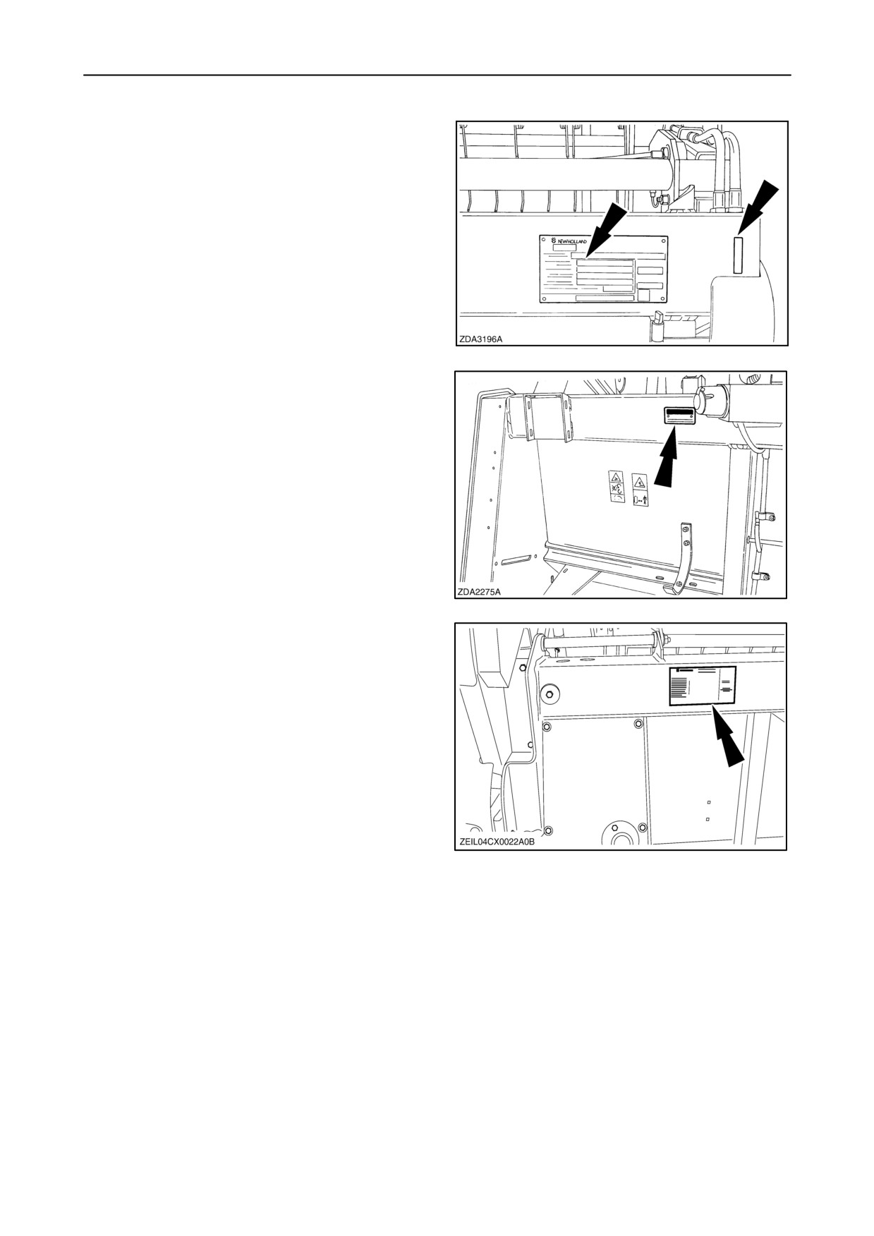
Grain header
(High-Capacity, Extra-Capacity or Varifeedt
)
In the right-hand upper corner of the header, and also
on a plate.
6
Maize header
On a plate positioned on the left-hand upper corner.
7
Flex header
On a plate positioned on the left-hand upper corner.
8
1-3
SECTION 1 - GENERAL INFORMATION AND SAFETY
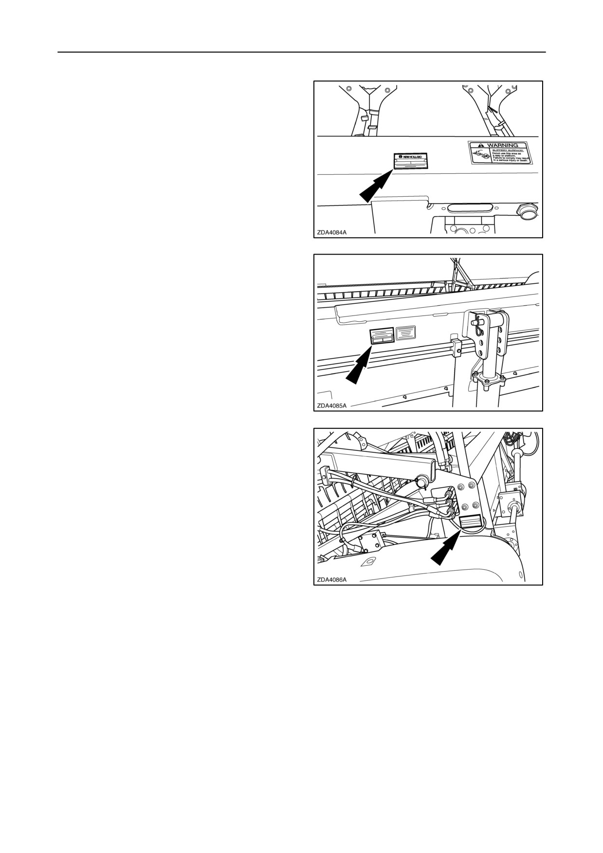
Maize header (98C)
On a plate positioned on the left-hand upper corner.
9
Draper header (92C/94C)
On a plate positioned on the left-hand upper corner.
10
Grain - Rice - Flex header (72C/74C)
On a plate positioned on the left-hand upper corner.
11
1-4
SECTION 1 - GENERAL INFORMATION AND SAFETY
Record below the serial numbers of your machine for quick reference:
Combine model
Combine serial number
Engine serial number
Grain header serial number
High-Capacity
Extra-Capacity
Varifeedt
Maize header serial number
Flex header serial number
Date machine first used
Dealer’s telephone number
1-5
SECTION 1 - GENERAL INFORMATION AND SAFETY
General recommendations
Most farm machinery accidents can be avoided by
the observance of a few simple safety precautions.
1. The machine must only be used by a skilled oper-
ator familiar with all the controls and harvesting
techniques on cultivated land with slopes up to
maximum 26% (15_) uphill and downhill, and
maximum 36% (19_) sideways [provided good
even ground and sufficient tyre adherence condi-
tions exist].
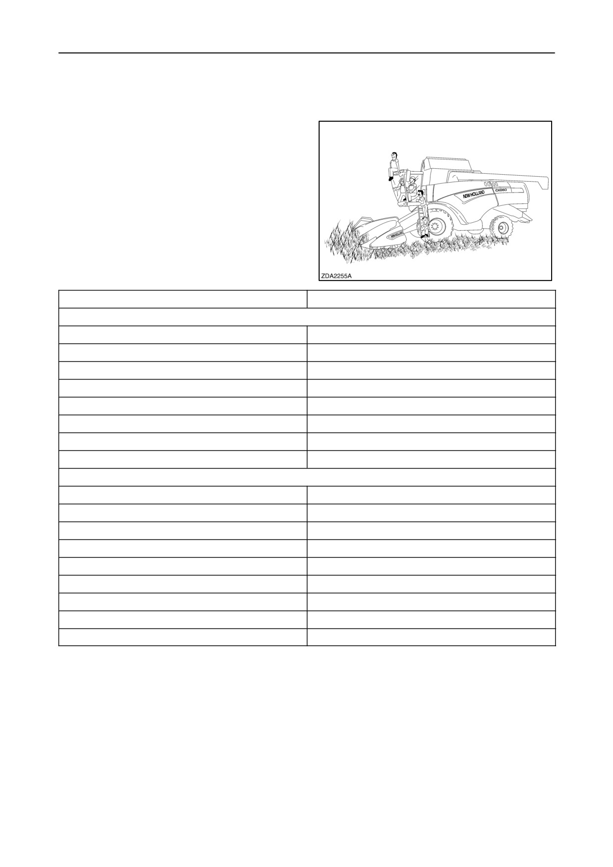
2. Never permit anyone other than the operator to
ride on the combine.
Traction tyres
Maximum side stability
CX720-740-760-780
620/75R34-170A8-DT820
30%
650/75R32-172A8-DT822 (on narrow track)
30%
650/75R32-172A8-DT822 (on wide track)
35%
800/65R32-172A8-DT822 (on narrow track)
35%
800/65R32-172A8-DT822 (on wide track)
40%
900/60R32-176A8-DT830 (on narrow track)
35%
900/60R32-176A8-DT830 (on wide track)
40%
1050/50R32-178A8-MegaXBib
40%
CX820-840-860-880
620/75R34-170A8-DT820
30%
650/75R32-172A8-DT822 (on narrow track)
30%
650/75R32-172A8-DT822 (on normal track)
35%
650/75R32-172A8-DT822 (on wide track)
40%
800/65R32-172A8-DT822 (on narrow track)
35%
800/65R32-172A8-DT822 (on wide track)
40%
900/60R32-176A8-DT830 (on narrow track)
35%
900/60R32-176A8-DT830 (on wide track)
40%
1050/50R32-178A8-MegaXBib
40%
1-6
SECTION 1 - GENERAL INFORMATION AND SAFETY
3. Before starting the engine, ensure everyone is
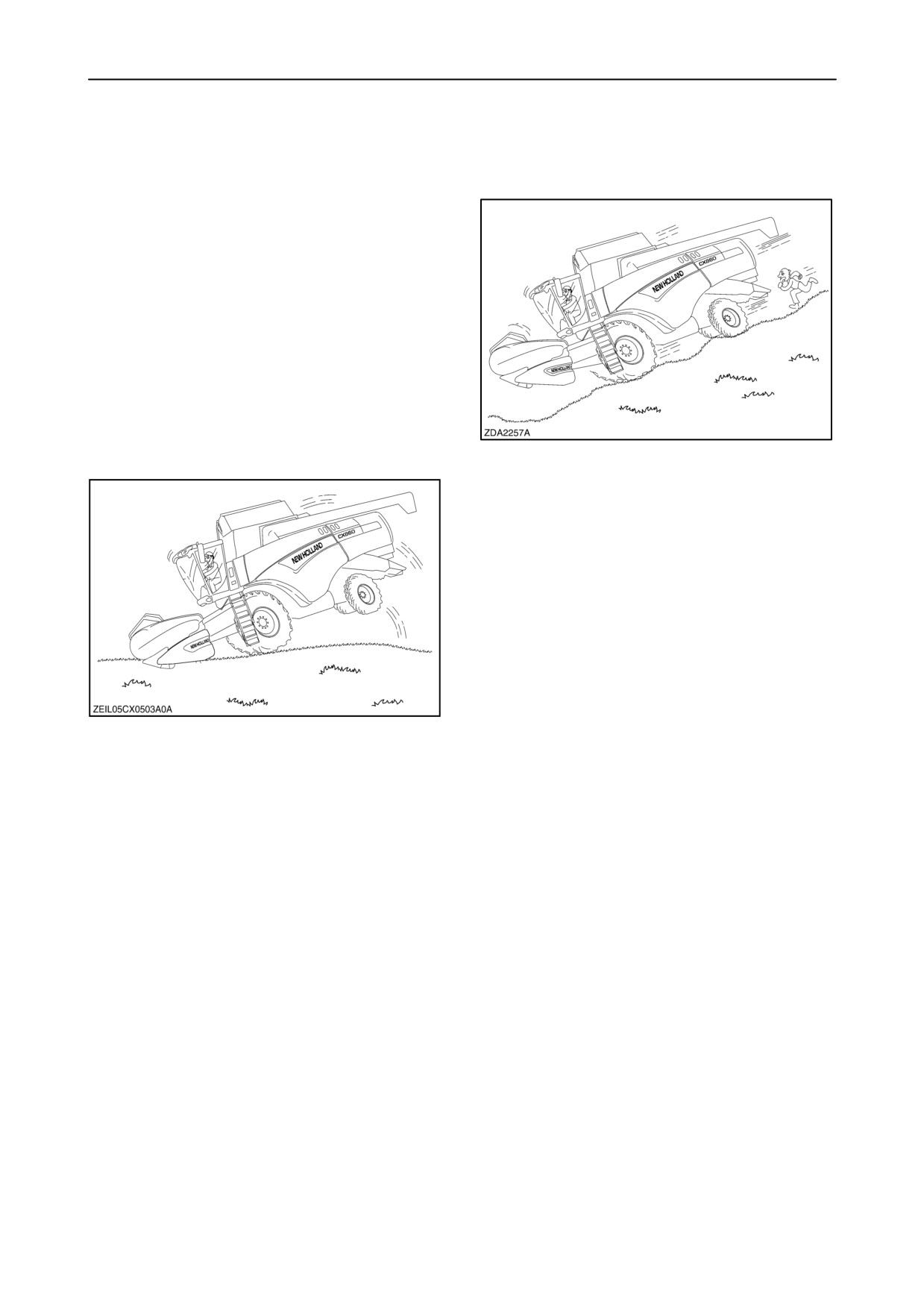
7. Never exceed 20 km/h when driving downhill. If
clear of the combine.
necessary, change into a lower gear before start-
ing the descent.
Warn bystanders by sounding the horn several
times.
4. Keep children away from and off the combine at
all times.
5. No-one should be standing on the ladders when
the machine is moving.
6. Never brake abruptly to avoid tipping of the ma-
chine.
8. Avoid making turns at high speed.
9. Before operating the combine ensure that all
safety guards are installed.
10. Never step on places on the machine which are
not foreseen with anti-slip strips.
11. Check the wheel nuts torque daily during the first
week of operation and thereafter on a weekly
basis. Tighten as described in “SECTION 8 -
SPECIFICATIONS”.
1-7
SECTION 1 - GENERAL INFORMATION AND SAFETY
12. The life and performance of the tyres depends
largely upon maintaining the correct pressure.
Keep the tyres inflated to the pressures given in
“SECTION 8 - SPECIFICATIONS”.
13. Never enter the grain tank while the combine en-
gine is running. Use a wooden clearing club if the
grain tank unloading auger becomes clogged.
Take utmost care not to be pulled into the grain
tank in case unplugging is required.
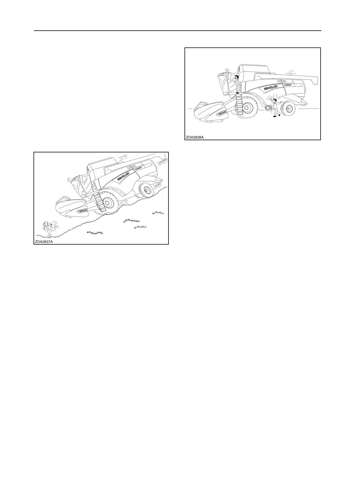
15. Keep hands away from moving parts of the com-
bine.
16. Keep the fire extinguisher within easy reach of the
operator. Ensure to replace it by a similar type of
extinguisher or have it checked or refilled after
every usage and/or date of expiry.
17. Never step on the cab roof.
18. Combine dust can cause ’’farmer’s lung’’ disease.
It may also contain nocive spraying residues.
Keep the cab door and window closed during
14. Never work around the combine in loose clothing
operation. Wear a dust mask when cleaning the
that might catch in any of the moving parts.
air filters or accumulated dust in the combine.
Starting up the combine
1. Never attempt to start up or manoeuvre the
3. Before starting the engine, always make sure that
combine unless you are sitting in the operator’s
the handbrake is engaged, the multifunction lever
seat.
and the gearshift control lever are in NEUTRAL
position, and the safety-on-the-road tumbler
2. Before starting up the combine (e.g. the first time
switch is in ROAD position.
after a long standstill period), make sure that
there are no detached loose part in the
4. Never run the engine in an enclosed area without
attachment, the drive line area and/or on the
ensuring adequate ventilation as exhaust fumes
rotary dust screen.
are toxic and, if inhaled, may be fatal.
1-8
SECTION 1 - GENERAL INFORMATION AND SAFETY
Travelling on public roads
1.
Make sure the safety-on-the-road tumbler switch
10. Always depress the brake pedal gently to avoid
is in ROAD position.
tipping of the machine.
2.
Always observe the local regulations. Should the
width of the attachment be wider than the
CAUTION
permitted road width, contact the local authorities
for assistance.
Before driving on the road with a header attached
3.
Observe traffic regulations, adapt your speed to
smaller than 4 meter (foldable grain header or flip-up
road and traffic conditions and ensure all lights
maize header), the following actions must be taken:
are working properly.
Contact your local dealer.
4.
Where required by local traffic regulations,
•
Counterweights
ensure the hazard warning plates are fitted at the
front and the rear of the machine.
•
Additional headligths
5.
Use the revolving flash lights to indicate the
•
Brake force limiter valve
vehicle has abnormal size and is slow-moving.
6.
Never drive on public roads with the operating
lights and spotlight switched on.
11. Never rest your feet on the brake pedals when the
machine is in motion.
7.
Dip the headlights when meeting a vehicle at
night. Make sure the lights are adjusted to
prevent blinding the driver of an oncoming
12. When manoeuvring the machine off the field,
vehicle.
always raise the attachment fully to avoid contact
with obstructions.
8.
Avoid taking corners at high speed.
13. The grain tank must be empty when driving on the
road. Ensure that the unloading tube is locked in
its closed position.
14. When driving on public roads, either with the grain
header loaded on a trailer and attached to the rear
of the combine, or with the grain header still
attached to the combine
(provided local
legislation allows), the knife should be
safeguarded by means of a knife guard, available
as an accessory (refer to the Grain Header
Operator’s Manual).
15. When driving on public roads, either with the grain
9.
Before travelling on the road, link the brake
header loaded on a trailer and attached to the rear
pedals together with the coupling provided.
of the combine, or with the grain header still at-
Braking with the pedals uncoupled may cause the
tached to the combine (provided local legislation
machine to swerve.
allows), always be aware and conscious of its
Also, avoid excessive use of the brakes.
size.
1-9
SECTION 1 - GENERAL INFORMATION AND SAFETY
Operating the combine
1.
Before operating the combine ensure that all
9.
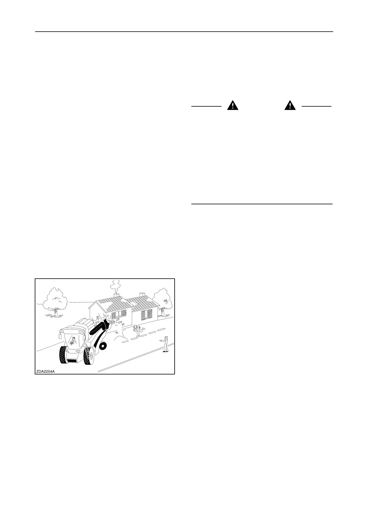
Danger of death by electrocution!
safety guards are properly fitted and secured.
Pay special attention to the overhead power
lines. Make sure the machine has sufficient
2.
Never attempt to clean, lubricate or carry out any
clearance to pass in all directions (also with
adjustments on the combine while it is in motion
raised or opened machine components). Also
or while the engine is running.
think of the radio aerial(s) or any other factory-
fitted accessory or parts which may have been
added afterwards.
3.
For safety’s sake never leave the operator’s plat-
Should a contact between the machine and an
form without first disengaging the combine drive
electric power line occur, then the following
mechanism, lowering the header, stopping the
precautions must be taken: Stop the machine
engine, applying the handbrake and removing the
movement immediately, stop the engine and
ignition key.
apply the handbrake.
Check if you can safely leave the cab or your
actual position without direct contact with electric
4.
Never climb on or off the machine when it is in mo-
wires. If not, stay in your position and call for help.
tion as there is a risk of being run over.
If you can leave your position without touching the
lines, jump off the last step or support position to
ensure that there is no contact between any part
5.
Use extreme caution when operating close to the
of your body and the ground at any time. Never
edge of a ditch or a steeply dropping embank-
touch the machine afterwards until power to the
ment.
lines has been shut off. When people approach
the machine, warn them not to touch the machine
but to ask the electric power supply company to
shut off the power to the lines.
6.
Avoid changing direction abruptly, especially
when reversing, to avoid dangerous pitching of
10. Never apply the differential lock when turning.
the machine. Lower the attachment if the ma-
When engaged, the differential lock will prevent
chine tends to lift at the rear.
the combine from turning.
11. Ensure the engine is shut off and wait until the
machine has completely stopped before opening
7.
Always operate the combine at a safe speed in
any of the guards.
accordance with the ground conditions.
On uneven ground, proceed with the utmost cau-
THERE ARE ROTATING PARTS UNDER THE
tion to ensure proper stability.
GUARDS WHICH MAY CONTINUE ROTATING
AFTER THE MACHINE HAS BEEN STOPPED.
8.
When operating on gradients, never drive too
Look and listen for evidence of rotating parts
fast, especially when turning.
before opening any of the guards.
1-10
SECTION 1 - GENERAL INFORMATION AND SAFETY
Operating the attachments
1. When coupling an attachment to the base unit,
4. Never attempt to remove crop or residues from a
never stand between the machine and the
plugged attachment while the machine is
attachment.
running. Such an imprudence could cost life or
limb. In the event of a blockage, always
2. Make sure that no one is standing in front of the
disengage the threshing mechanism, switch off
machine when detaching an attachment.
the harvester engine and apply the parking brake
3. Before operating the attachment, make sure that
before clearing the blockage.
there is no one on or near the machine.
Stopping the combine
1. Always lower the attachment to the ground when
3. When parking, always try to leave the machine on
parking the machine.
level ground and apply the parking brake. If the
ground is sloping, apply the parking brake and
2. For safety’s sake never leave the operator’s
wedge the wheels.
platform without first returning the ground speed
control lever to neutral, switching off the threshing
mechanism, engaging the parking brake and
stopping the engine. Furthermore, if leaving the
machine unattended, always remove the ignition
key and switch off the switch on the battery.
Maintenance
1. Follow the maintenance schedule with regard to
safety latch is engaged or that it is securely sup-
the machine servicing intervals.
ported on wooden blocks.
Remember that the machine requires minor
attention from time to time. Also remember that
the time taken on maintenance will greatly extend
the life of the machine.
2. Never attempt to clean, lubricate or carry out any
adjustments on the combine while it is in motion
or while the engine is running.
3. Keep hands, feet and/or garments away from
moving parts. Check that all rotating parts are
correctly guarded.
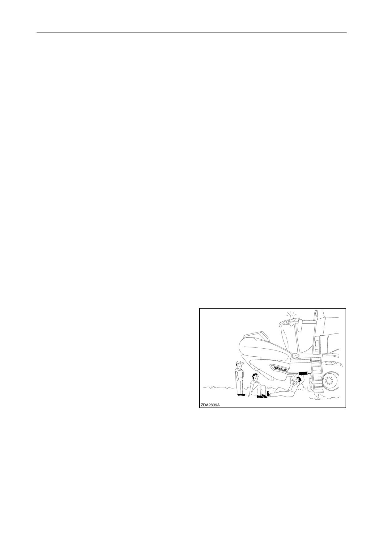
4. Never work under the attachment without first en-
5. Always use suitable jack stands when carrying
suring that the straw elevator hydraulic cylinder
out maintenance on the steering axle.
1-11

SECTION 1 - GENERAL INFORMATION AND SAFETY
6. Keep the combine, particularly the brakes and
14. Remove all tools from the machine after carrying
steering, maintained in a reliable and satisfactory
out any lubrication, maintenance or repair work.
condition to ensure your safety and compliance
Also, make sure that all components have been
with legal requirements.
securely tightened and all guards properly fitted.
Regularly check the efficiency of the brakes and
Replace or repair damaged guards immediately.
replace the brake pads before they are totally
worn out.
15. Combine wheels are very heavy. Handle with
care and ensure, when stored, that they cannot
7. Any leakage of hydraulic oil under pressure may
topple over and cause injury.
cause severe injury, so always use a shield,
goggles and gloves when tracing oil leaks.
16. Never work on the tyres unless you have the
special tools and the necessary experience.
Incorrect fitting could be a serious safety hazard.
If in doubt, call in qualified personnel.
8. Never construct flexible hose assemblies from
hoses which have been previously used as part
of a hose assembly.
9. Never weld to the piping.
17. Never attempt to service the air conditioning
10. When flexible hoses or pipings are damaged,
system. You may be severely frost bitten or
injured by escaping refrigerant. Special
replace them immediately.
equipment and instruments are required to
service the air conditioning system. Contact an
11. Always replace worn or frayed belts before they
authorised dealer for service.
fail.
12. Always disconnect the battery earth lead before
18. Adhere to all recommendations that are
carrying out any work on the electrical system.
mentioned in this manual such as service
intervals, torques, lubricants, etc.
13. Disconnect the alternator wires and the battery
cables before carrying out any electrical welding
on the machine. In addition, attach the earth
cable of the electric welder as close as possible
to the area to be welded.
1-12
SECTION 1 - GENERAL INFORMATION AND SAFETY
Engine
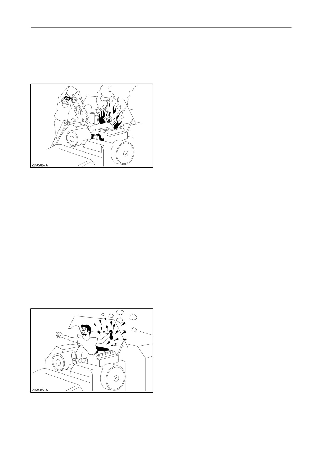
1. Keep the engine area clean of dust, chaff and
Failure to follow these instructions may result in
straw to prevent the possibility of fires.
serious personal injury from hot coolant or steam
blowout and/or damage to the cooling system or
engine.
5. Antifreeze contains monoethylene glycol and
other chemicals which are toxic if taken internally
and can be absorbed in toxic amounts through re-
peated or prolonged skin contact. Follow these
precautions when working with antifreeze:
• Never take antifreeze internally. If antifreeze
is swallowed accidentally, obtain medical
attention immediately.
• Keep antifreeze in sealed containers out of
2. Never idle the engine in an enclosed area as
reach of children, livestock or pets.
harmful exhaust gases may build up.
3. Wear a suitable hearing protective device, such
as ear muffs or ear plugs, if you are exposed to
noise which you feel is uncomfortable.
6. The fuel oil in the injection system is under high
pressure and can penetrate the skin. Unqualified
4. The cooling system operates under pressure
persons should not remove or attempt to adjust
which is controlled by the radiator cap. It is dan-
a fuel injection pump, injector, nozzle or any other
gerous to remove the cap while the engine is hot.
part of the fuel injection system. Failure to follow
these instructions may result in serious injury.
• Switch off the engine and wait until it has
If fuel is injected through the skin, medical assist-
cooled. Even then use extreme care when
ance should be obtained.
removing the cap. Cover the cap with a rag
and turn it slowly to the first stop to allow the
pressure to escape before removing the cap
completely. Stand clear of the radiator
opening as hot coolant may splash out.
7. Be very careful to avoid contact with hot engine
oil. If the engine oil is extremely hot, allow the oil
• Never add cold water to a hot radiator.
to cool to a moderately warm temperature for
safe removal.
8. Never handle a hot oil filter with bare hands.
9. Continuous and prolonged contact with used en-
gine oil may cause skin cancer. Protect your skin
by wearing heavy plastic gloves. If oil gets onto
the skin, wash promptly with soap and water.
1-13
SECTION 1 - GENERAL INFORMATION AND SAFETY
Diesel fuel
1. Under no circumstances should gasoline, alcohol
4. Never fill the fuel tank to capacity. Allow room for
or blended fuels be added to diesel fuel. These
expansion.
combinations can create an increased fire or ex-
plosive hazard. In a closed container, such as a
5. Wipe up spilled fuel immediately.
fuel tank, such blends are more explosive than
pure gasoline. Never use these blends.
6. Always tighten the fuel tank cap securely.
2. Never remove the fuel tank cap or refuel with the
7. If the original fuel tank cap is lost, replace it with
engine running or hot.
an approved cap. A non approved, proprietary
Refuel the combine fuel tank only when the en-
cap may not be safe.
gine has been turned off.
Never smoke or use a naked flame when refuel-
8. Keep equipment clean and properly maintained.
ling or when standing near fuel tanks.
9. Never drive equipment near open fires.
3. Maintain control of the fuel filler pipe nozzle when
filling the tank.
10. Never use fuel for cleaning purposes.
1-14

SECTION 1 - GENERAL INFORMATION AND SAFETY
Battery warning
CAUTION
The battery contains a sulphuric acid electrolyte
which may cause severe burns and produce
explosive gases. Avoid contact with the skin, eyes or
clothing. Never take internally.
The essential precautions listed must be observed:
• Never use a naked flame to check the electrolyte
level. Keep sparks, flames and lighted tobacco
away.
• Never produce sparks with cable clamps when
charging the battery or starting the engine with a
slave battery.
• Wear eye protection when working near
batteries.
• Provide ventilation when charging or using in an
enclosed space.
• Ensure the vent plugs are correctly installed and
tight.
If the electrolyte comes into contact with the skin,
eyes or is taken internally, treat as follows:
Skin:
Flush with cold water.
Eyes:
Flush with cold water for 10 minutes
and get prompt medical attention.
Internal:
Call a doctor immediately.
Illustrations
NOTE: Some of the illustrations in this Manual have
been obtained by photographing prototypes.
Standard production machines may differ in some
details.
CAUTION
In some of the illustrations in this Manual the guards
or covers have been removed for clarity. Never
operate the machine with these protective guards or
covers removed.
1-15
SECTION 1 - GENERAL INFORMATION AND SAFETY
Stability
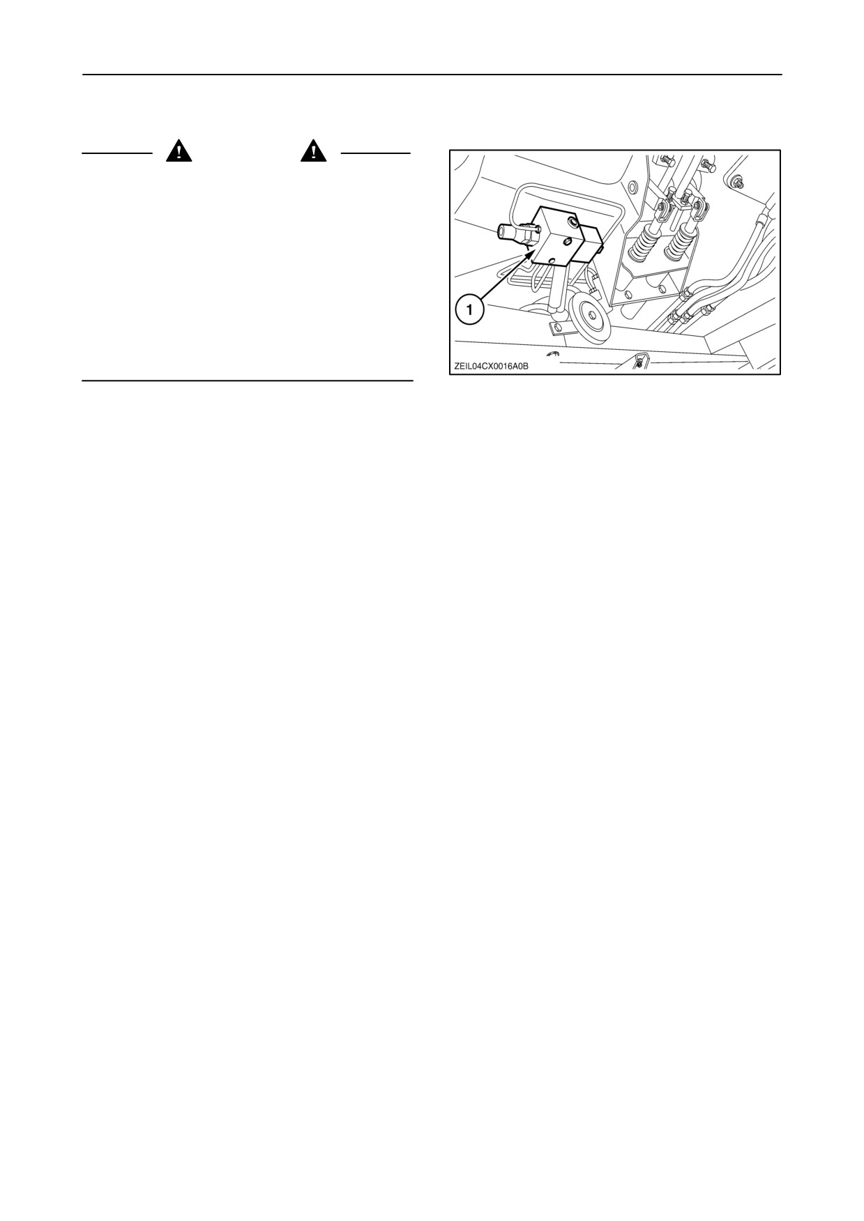
WARNING
To maintain safe stability and tracking characteristics
during braking, the installation of a brake force
limiting valve (1) is mandatory when travelling on the
road with foldable front attachment installed.
In addition, always make sure the correct number of
ballast weights corresponding to the attachment
installed is mounted at the rear of the unit. Refer to
“SECTION
8
- SPECIFICATIONS”, headed
counterweights.
(This brake force limiting valve is only operative when
road mode is selected).
LEGAL OBLIGATIONS
Your machine may be equipped with special guarding
When flexible hoses or piping are damaged, replace
or other devices in compliance with local legislation.
them immediately.
Some of these require active action by the operator.
It is forbidden to modify a hydraulic accumulator by
Therefore, check local legislation on the usage of this
machining, welding or any other means.
machine.
Before removing hydraulic accumulators for
SAFETY REQUIREMENTS FOR FLUID
servicing, the liquid pressure in the accumulator must
POWER SYSTEMS AND COMPONENTS
be reduced to zero.
- HYDRAULICS
(EUROPEAN STANDARD EN 982)
Pressure check on hydraulic accumulators shall be
carried out by method recommended by the
Flexible hose assemblies may not be constructed
accumulator manufacturer.
from hoses which have been previously used as part
of a hose assembly.
Care must be taken not to exceed the maximum
allowable pressure of the accumulator. After any
Never weld hydraulic piping.
check of adjustment there must be no leakage of gas.
1-16

SECTION 1 - GENERAL INFORMATION AND SAFETY
AIRBORNE NOISE EMISSION
ELECTROMAGNETIC COMPATIBILITY
(EMC)
In line with the European directive (CEE/86/188) and
national legislation, listed below are the noise levels
This product complies with the EEC directive 89/336
at the operator’s ear measured in dBa, according to
and its amendments on Electromagnetic
the ISO 5131 standard.
Interferences on electronic equipment if it is used in
conjunction with equipment which bears the CE
The noise is measured with the engine and all
mark.
mechanisms engaged and running at normal
operating speed for the specified use of the product
New Holland will take no liability for any problem
and without crop flow through the machine. For
arising as a result of its product working in an
machines with a cab, the noise is measured with all
environment of other equipment which does not
windows and doors closed and also in the open
comply with the EEC directive.
position.
Disturbances remain possible if added non New
It should be noted that the noise level may exceed 85
Holland equipment does not meet the standards. As
dBa if the machine is operating with doors and/or
these interferences may result in serious malfunction
windows open.
of the machine and/or create unsafe situations the
following instructions must be observed:
In this case, the use of ear protection equipment is
recommended. In several countries this is
Each element of non New Holland equipment added
mandatory, so check local legislation.
to this New Holland product must bear a CE mark.
The maximum power of emission equipment (radio,
Machine
Engine model
Noise level (dBa)
telephones, etc.) must not exceed the limits imposed
model
Cab doors and
by the national authorities of the country of usage of
windows closed
the machine.
CX720
CNH 675 TA/AG
75
The electromagnetic field generated by the added
system must not exceed 24 V/m at any moment and
at any location in the proximity of electronic
CX740
CNH 675 TA/AH
75
components and the network between them over the
entire machine.
CX760
CNH 675 TA/AJ
75
CX780
CNH 675 TA/AB
75
VIBRATION LEVEL INFORMATION
CX820
CNH 675 TA/AJ
75
The vibration level for the arms to which the operator
of this machine is exposed under normal operating
CX840
CNH 675 TA/AB
75
conditions is below the 2.5 m/sec@ weighted root
mean square (RMS) value. The vibration level for the
whole body is below the 0.5 m/sec@ RMS value.
CX860
IVECO F2B
75
This information and measuring methods are in line
CX880
IVECO F3A
75
with the European Machinery Directive 98/37/EC
paragraph 3.6.3.
1-17
SECTION 1 - GENERAL INFORMATION AND SAFETY
SAFETY DECALS
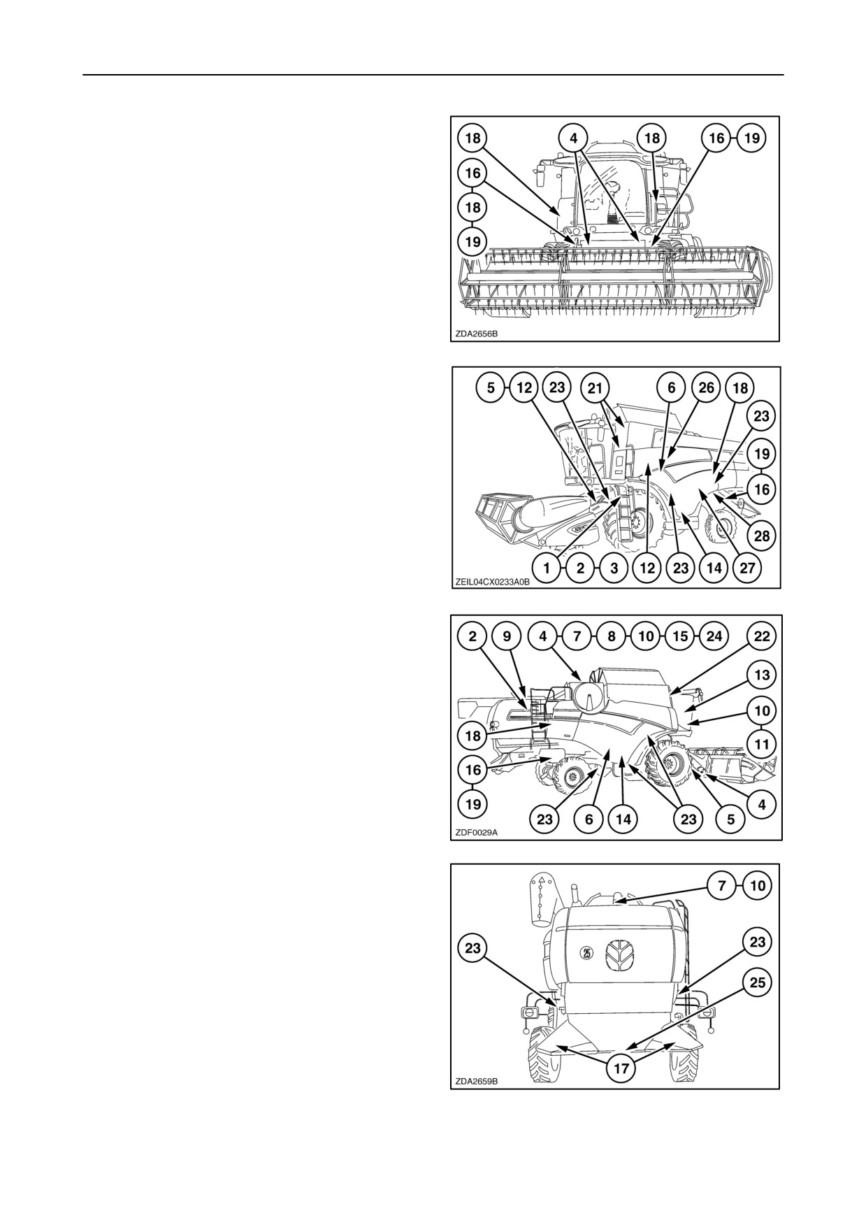
The following safety decals have been placed on your
machine in the areas indicated. They are intended for
your personal safety and for those working with you.
12
Please take this manual and walk around your
machine, noting the location of the decals and their
significance.
13
Review these decals and the operating instructions
detailed in this Manual with the machine operators.
14
Keep the decals clean and legible. If they become
damaged or illegible, obtain replacements from your
New Holland dealer.
15
1-18
SECTION 1 - GENERAL INFORMATION AND SAFETY
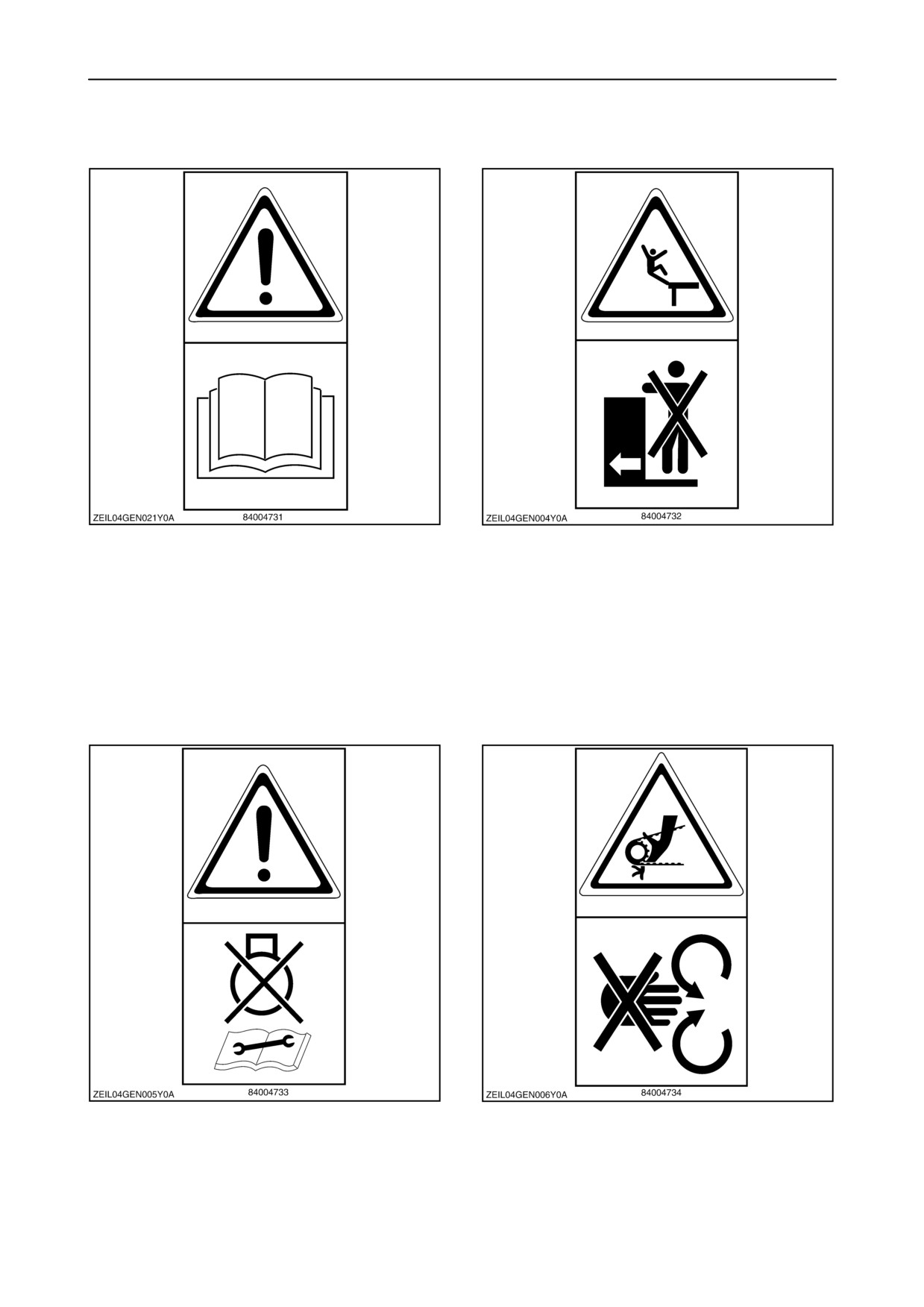
Decal 1
Decal 2
Carefully read the Operator’s Manual before
Never ride on platform or ladder.
operating the machine. Observe instructions and
safety rules when operating.
Decal 3
Decal 4
Disengage all drives, stop the engine and wait until
Never open or remove safety shields while engine is
moving parts have stopped before cleaning or
running.
servicing the machine.
1-19
SECTION 1 - GENERAL INFORMATION AND SAFETY
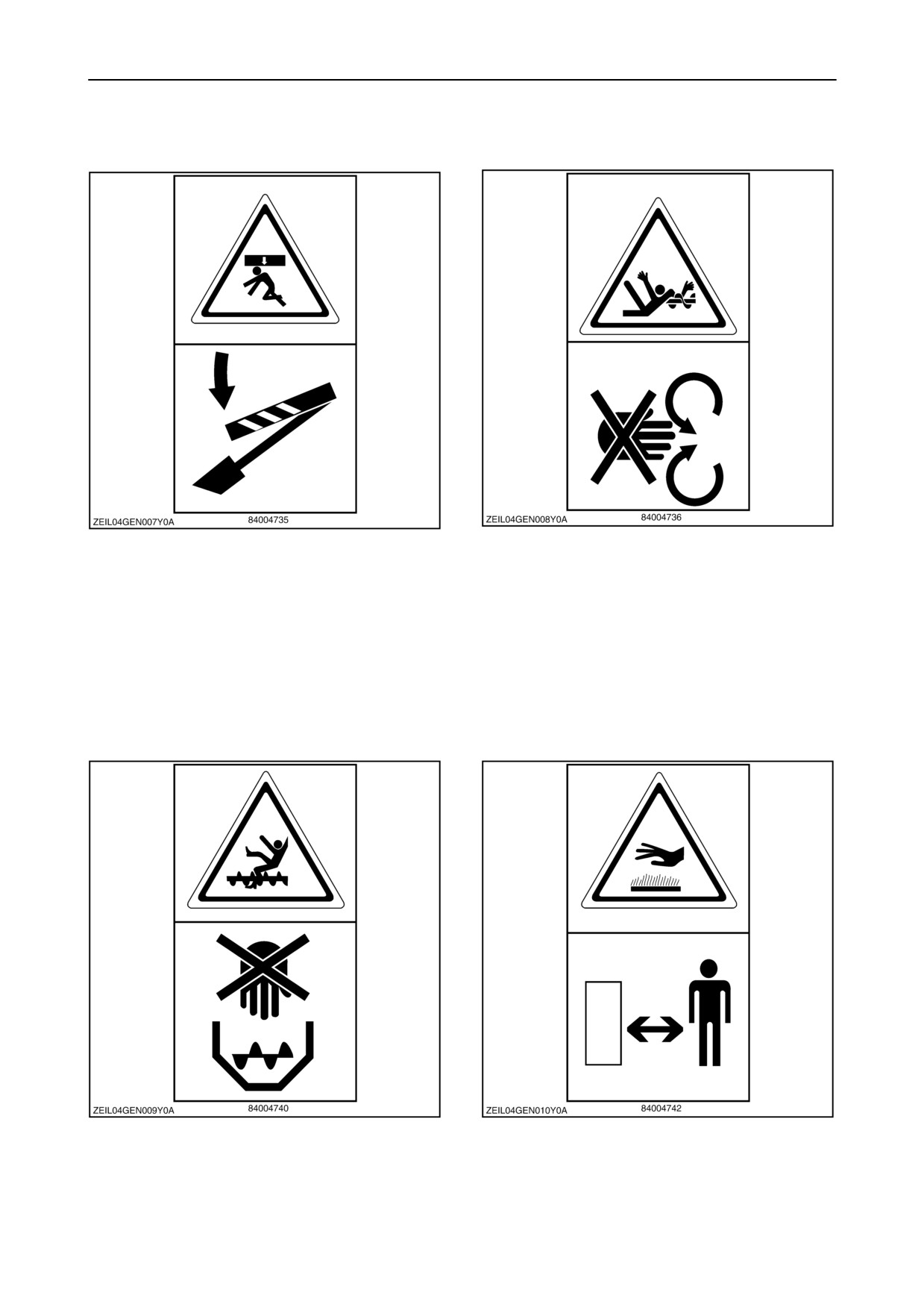
Decal 5
Decal 6
Never reach into rotating auger.
Secure lift cylinder locking device before getting in
dangerous area.
Decal 7
Decal 8
Never reach or climb into grain tank while engine is
Stay clear of hot surface.
running.
1-20
SECTION 1 - GENERAL INFORMATION AND SAFETY
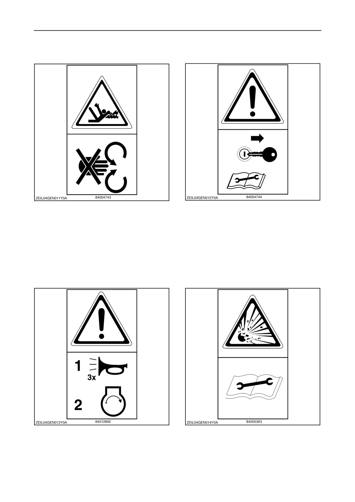
Decal 9
Decal 10
Never reach into straw walkers while engine is
Shut off engine and remove ignition key before
running.
performing maintenance or repair work.
Decal 11
Decal 12
Sound the horn 3 times before starting the engine.
Hydraulic accumulators contain gas and oil under
pressure. For removal and repair, contact your local
New Holland dealer.
1-21
SECTION 1 - GENERAL INFORMATION AND SAFETY
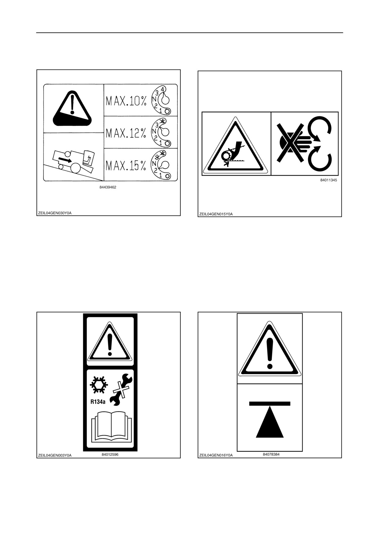
Decal 13
Decal 14
To prevent runaway of the combine (i.e. when the
Never open or remove safety guard while engine is
ground speed increases during downhill driving and
running.
it is impossible to reduce speed with the ground
speed control lever), it is necessary to shift into a
lower gear appropriate to the steepness of the hill
before starting the descent.
Decal 15
Decal 16
R 134a cooling gas. For removal and repair contact
Jack up point.
your local New Holland dealer.
1-22
SECTION 1 - GENERAL INFORMATION AND SAFETY
Decal 17
Decal 18
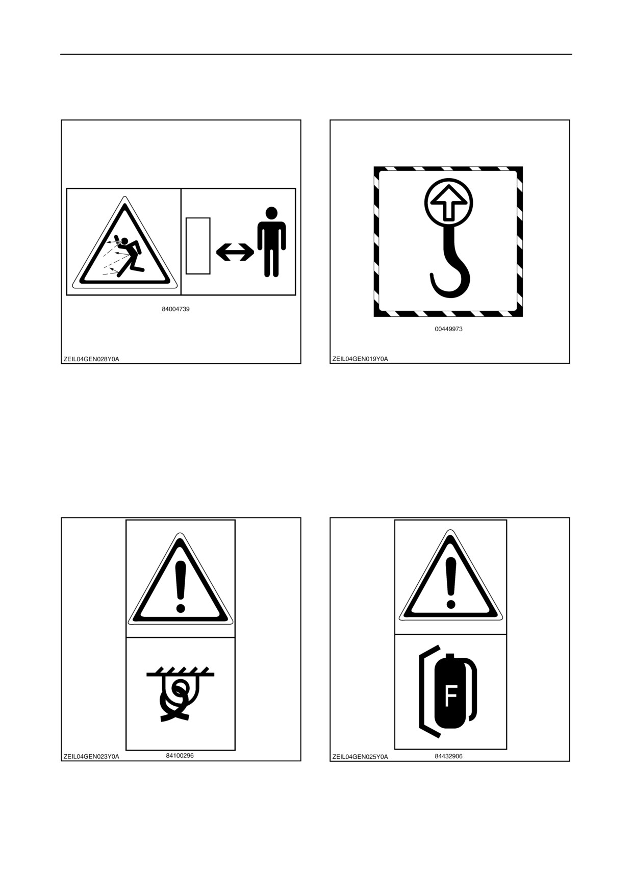
DANGER:
Lifting eye / pulling eye.
Stay clear while engine is running.
Decal 19
Decal 20
Tie-down eye.
Only operate when approved fire extinguisher is
installed.
1-23
//////////////////////////////////////////