New Holland CX720, CX740, CX760, CX780, CX820, CX840, CX860, CX880. Operator's Manual - page 5
SECTION 2 - CONTROLS, INSTRUMENTS AND OPERATION
Current settings
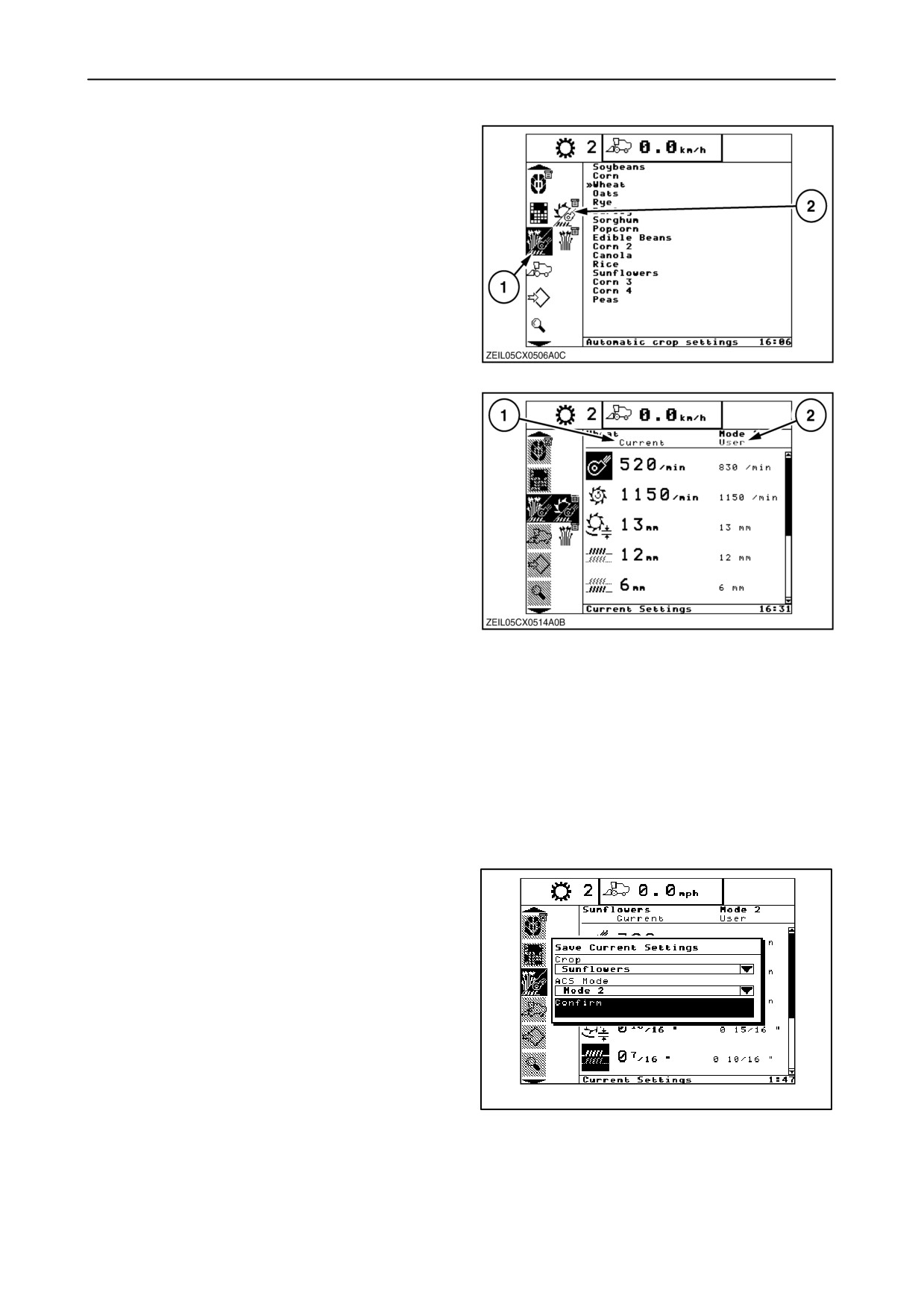
1. Select the Automatic Crop Settings screen 1 in
the menu bar.
2. Select the current settings sub-menu 2.
148
3. The current settings screens allow the operator to
monitor and save machine settings while
threshing.
4. The following settings are controlled as current
settings:
• Cleaning fan RPM
• Thresher RPM
• Concave clearance
• Auto reel speed offset
Additional equipment (if installed)
149
• Upper sieve opening
• Lower sieve opening
• Reel horizontal position
• Reel verical position
5. The current machine settings 1 and the stored
settings 2 for the current crop and ACS mode are
displayed in two columns. If the two columns are
not identical, the icon will be highlighted. All items
on this page are read only. The operator can only
change the current settings via the switches on
the right-hand module or multifunction handle.
6. To save the current machine settings, press
Enter, to open the Save Current Settings pop-up.
The “Confirm” option will be highlighted. To save
the settings to the current crop and ACS mode,
press “enter” again. It is only necessary to use the
drop down menus if the operator wants to save
the settings for a different crop or ACS mode.
20040173
150
2-90
SECTION 2 - CONTROLS, INSTRUMENTS AND OPERATION
VI COMBINE INFO SCREEN
Switch to the combine information screen as follows:
1. Select the combine info menu in the menu bar by
using the up and down navigation keys.
2. A sub-menu will appear next to the menu bar.
3. To enter that sub-menu, press the
”right”
navigation key.
4. Run through the sub-menu by using the up and
down navigation keys:
151
The ”up” key to select a screen up the ladder.
The ”down” key to select a screen down the
ladder.
Keeping the ”up” and ”down” navigation key
depressed will shift the menu quickly up or down.
The selected symbol always remains in the
middle of the menu bar and blinks to show the
selected position. When the navigation keys are
not used for a while, the selected symbol will stop
blinking and will be inverted until the navigation
keys are used again.
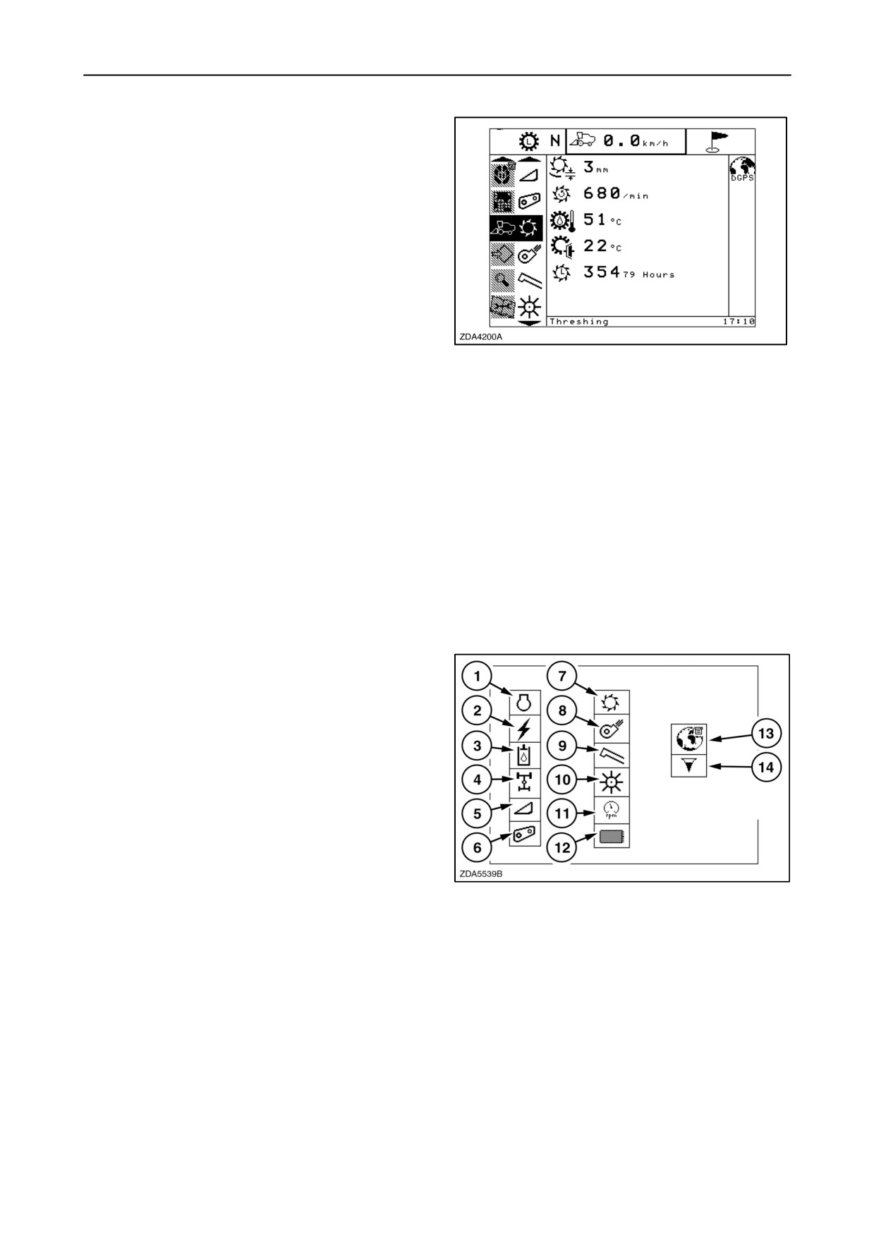
The different sub-menus in the combine information
menu are shown in figure 152 and will always appear
in that sequence.
1. Engine
2. Electrical
3. Hydraulics
4. Driveline
5. Header
6. Straw elevator
7. Threshing
8. Cleaning
152
9. Clean grain/unload
10. Residue
11. RPM info
12. Data logger info (if installed)
13. GPS info (if installed)
14. Loss info
In these sub menus information can be found in
relation to the selected sub menu.
2-91
SECTION 2 - CONTROLS, INSTRUMENTS AND OPERATION
VII CONFIGURATIONS AND CALIBRATIONS
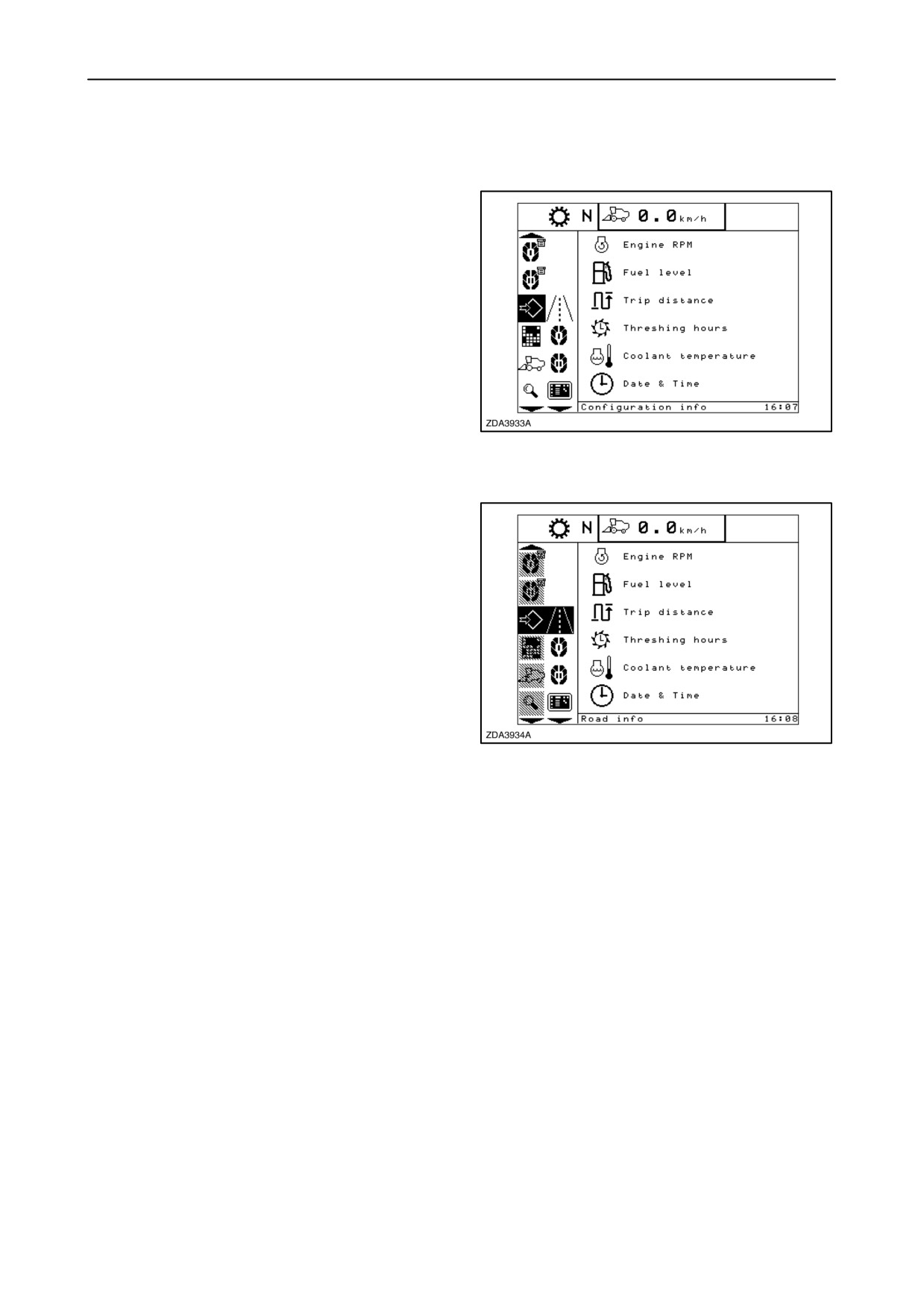
In this menu the operator will be able to configure his
machine. A lot of configurations and settings are
factory-set and can not be changed.
Switch to the configuration menu as follows:
1. Select the configuration menu in the menu bar by
using the up and down navigation keys.
2. A sub-menu will appear next to the menu bar.
153
3. To enter the sub-menu bar, press the “right”
navigation key.
4. Run through the sub-menu by using the up and
down navigation keys:
The “up” key to select a screen ups the ladder.
The “down” key to select a screen down the
ladder.
Keeping the “up” and “down” navigation key
depressed will shift the menu quickly up or down.
154
The selected symbol always remains in the
middle of the menu bar and blinks to show the
selected position. When the navigation keys are
not used for a while, the selected symbol will stop
blinking and will be inverted until the navigation
keys are used again.
2-92
SECTION 2 - CONTROLS, INSTRUMENTS AND OPERATION
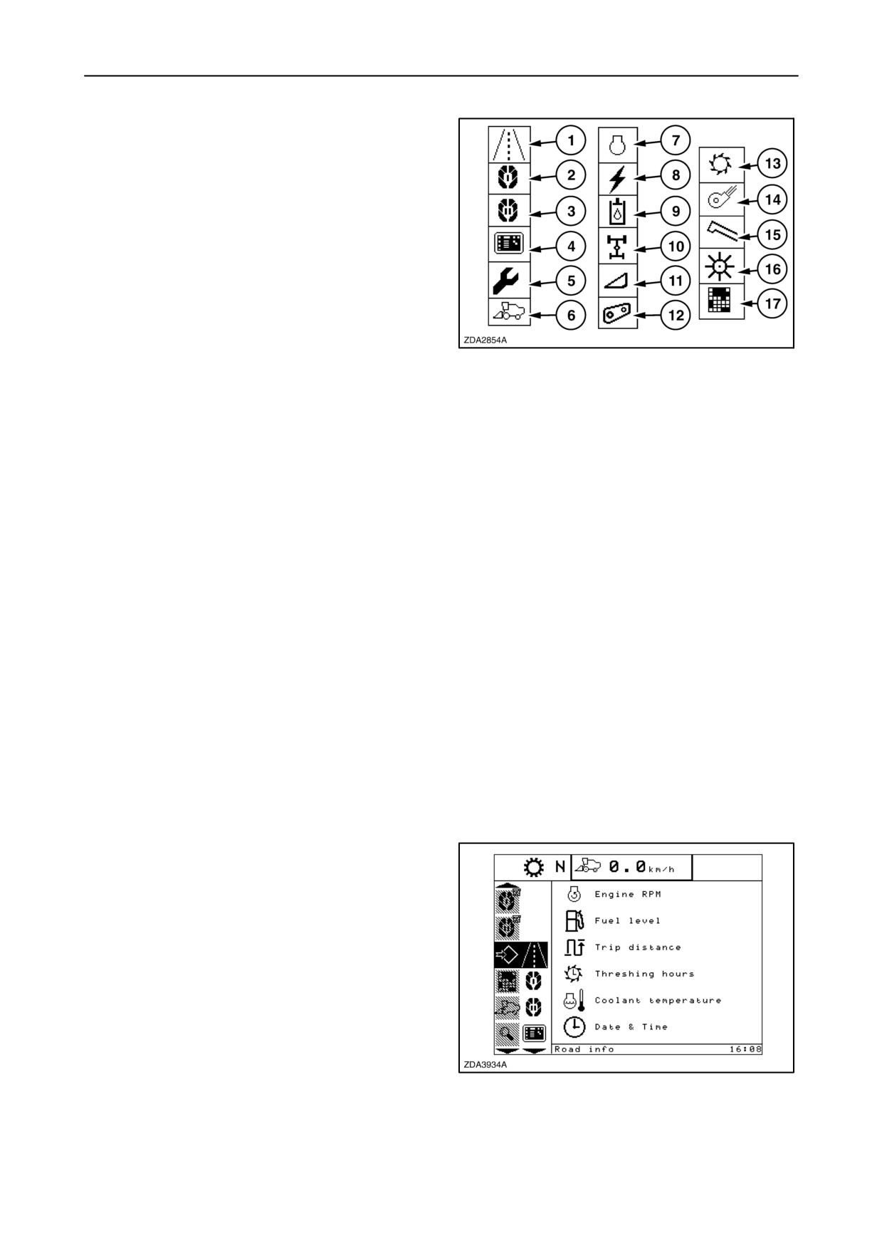
The different sub-menus in the configuration menu
are shown in figure 155 and will always appear in that
sequence.
1. Road info screen setup
2. Main info screen setup
3. Custom info screen setup
4. Display settings
5. Calibration
6. Combine
7. Engine
8. Electrical
155
9. Hydraulics
10. Driveline
11. Header
12. Straw elevator
13. Threshing
14. Cleaning
15. Clean grain/Unload
16. Residue
17. Precision farming
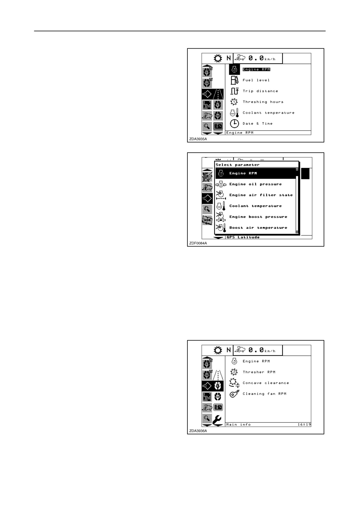
1. Road info screen setup
This screen set-up enables the operator to make a
display layout of the road info screen according to his
own preferences.
The operator can decide which information is
displayed in the road mode screen.
To change the road info screen setup, proceed as
follows:
1. Select the road info screen setup in the
configuration sub-menu.
156
2-93
SECTION 2 - CONTROLS, INSTRUMENTS AND OPERATION
2. Press the ”right” navigation key to enter the
information window.
3. Use the ”up” and ”down” navigation keys to select
the item to change and press “enter”.
157
4. A pop-up screen appears with a list of possible
choices.
5. Select by pressing the ”up” and ”down” navigation
keys to change the content on that item.
6. Press the ”enter” key to confirm your choice.
NOTE: Find the possible choices in table ”Pages
setup”.
158
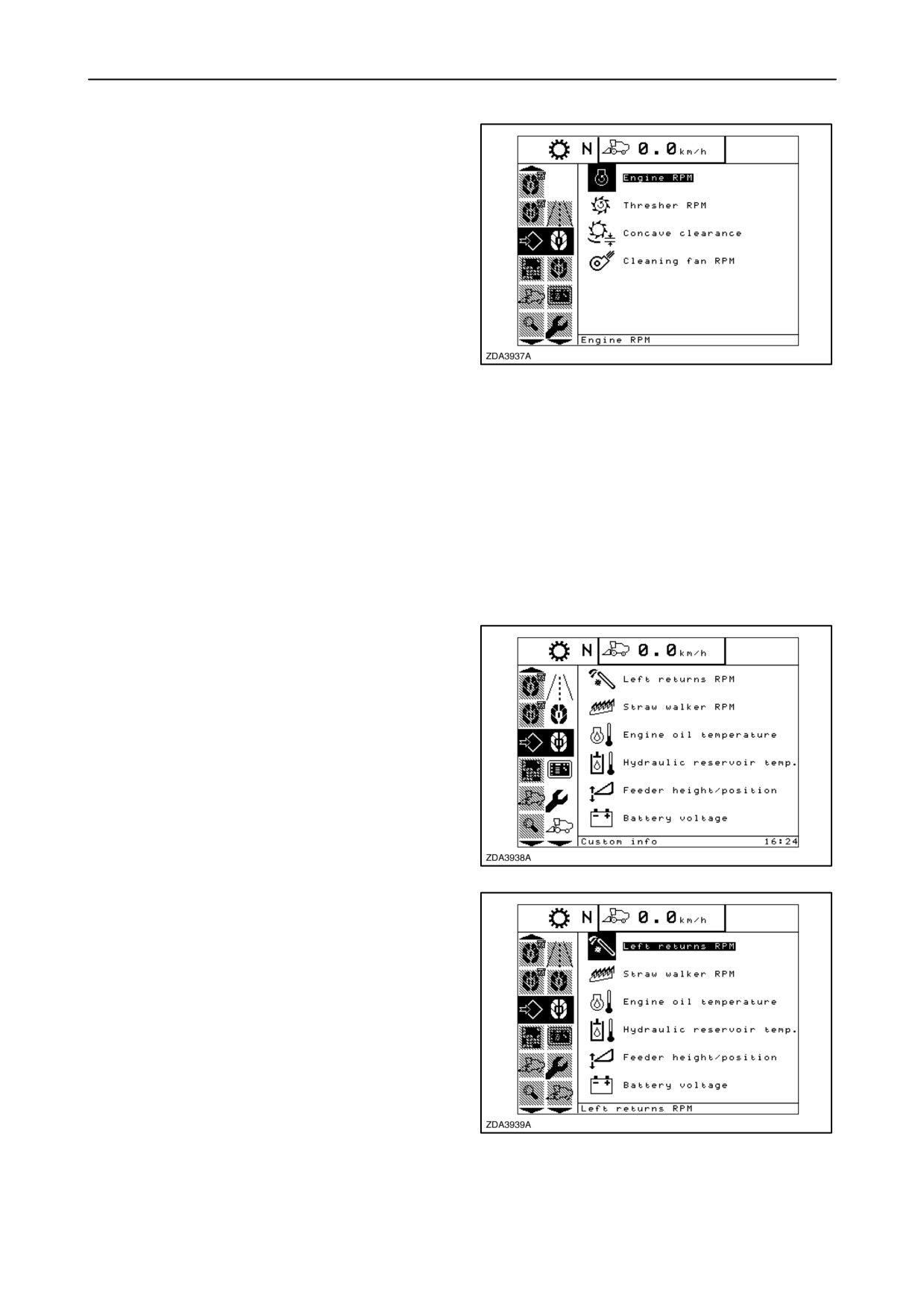
2. Main info screen setup
This screen setup enables the operator to make a
display layout of the main info screen according to
own preferences.
The operator can decide which information is
displayed in the main info screen.
To change the main work screen setup, proceed as
follows:
1. Select the main info screen setup in the
configuration sub-menu.
159
2-94
SECTION 2 - CONTROLS, INSTRUMENTS AND OPERATION
2. Press the ”right” navigation key to enter the
information window.
3. Use the ”up” and ”down” navigation keys to select
the item to change and press “enter”.
4. A pop-up screen appears with a list of possible
choices.
5. Select by pressing the ”up” and ”down” navigation
keys to change the content on that item.
6. Press the ”enter” key to confirm your choice.
NOTE: Find the possible choices in table ”Pages
160
setup”.
3. Custom info screen setup
This screen setup enables the operator to make a
display layout of the custom screen according to own
preferences.
The operator can decide which information is
displayed in the custom info screen.
To change the custom info screen setup, proceed as
follows:
1. Select the custom info screen setup in the
configuration sub-menu.
161
2. Press the ”right” navigation key to enter the
information window.
3. Use the ”up” and ”down” navigation keys to select
the item to change and press “enter”.
4. A pop-up screen appears with a list of possible
choices.
5. Select by pressing the ”up” and ”down” navigation
keys to change the content on that item.
6. Press the ”enter” key to confirm your choice.
NOTE: Find the possible choices in table ”Pages
162
setup”.
2-95
SECTION 2 - CONTROLS, INSTRUMENTS AND OPERATION
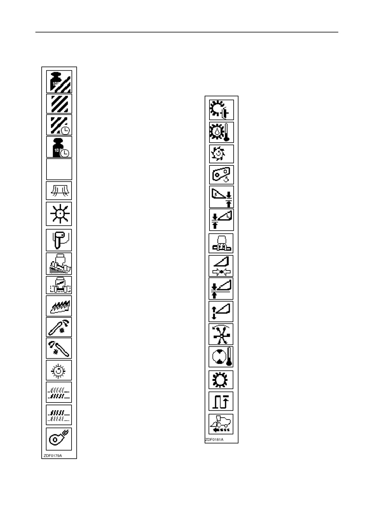
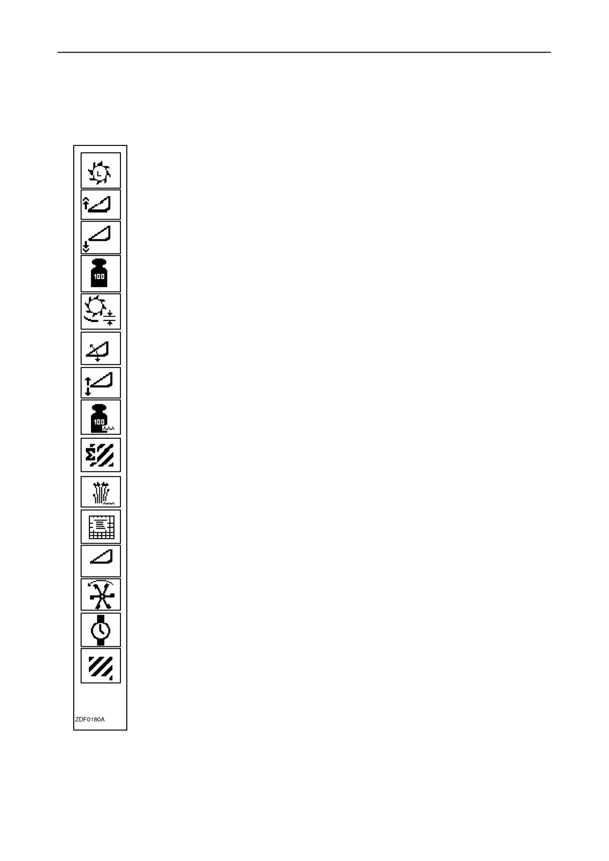
Page Setup
Yield (Ton/ha - Bu/acre)
Area
Engine gearbox clutch temp.
Harvesting rate
Engine gearbox temperature
Mass flow
Drum rpm
Blank
Straw elevator rpm
Spreader plate position
Skid plate / Flex right
Straw chopper rpm
Skid plate / Flex left
Grain elevator rpm
Header lateral tilt
Combine lateral inclination
Header lift pressure
Cleaning shoe angle
Mean stubble height
Straw walker rpm
Header height/position
Right returns rpm
Header reel rpm
Left returns rpm
Hydrostatic motor temperature
Rotary separator rpm
Transmission shift gear
Lower sieve opening
Trip distance
Upper sieve opening
Ground speed
Cleaning fan rpm
2-96
SECTION 2 - CONTROLS, INSTRUMENTS AND OPERATION
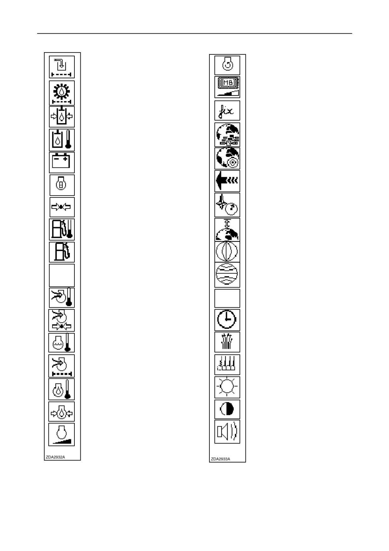
Engine rpm
Return filter state
Datacard space left
Gearbox filter state
GPS Fix type
Control pressure
GPS Satellites Visible
Hydraulic reservoir temp.
GPS HDOP
Battery voltage
Engine hours
GPS speed
Atmospheric pressure
GPS heading
Fuel temperature
GPS altitude
Fuel level
GPS longitude
Blank
GPS latitude
Engine boost air temperature
Blank
Engine boost pressure
Date & Time
Coolant temperature
Crop
Engine air filter state
Rows in use
LCD Night Brightness
Engine oil temperature
Engine oil pressure
LCD Contrast
Engine load
Speaker volume
2-97
SECTION 2 - CONTROLS, INSTRUMENTS AND OPERATION
Threshing hours
Header raise rate
Header lower rate
Dry mass
Concave clearance
Tilt sensitivity
Height sensitivity
Wet mass
Total area
Moisture content
Job
Header type
Auto reel speed offset
Elapsed time
Area harvested
2-98
SECTION 2 - CONTROLS, INSTRUMENTS AND OPERATION
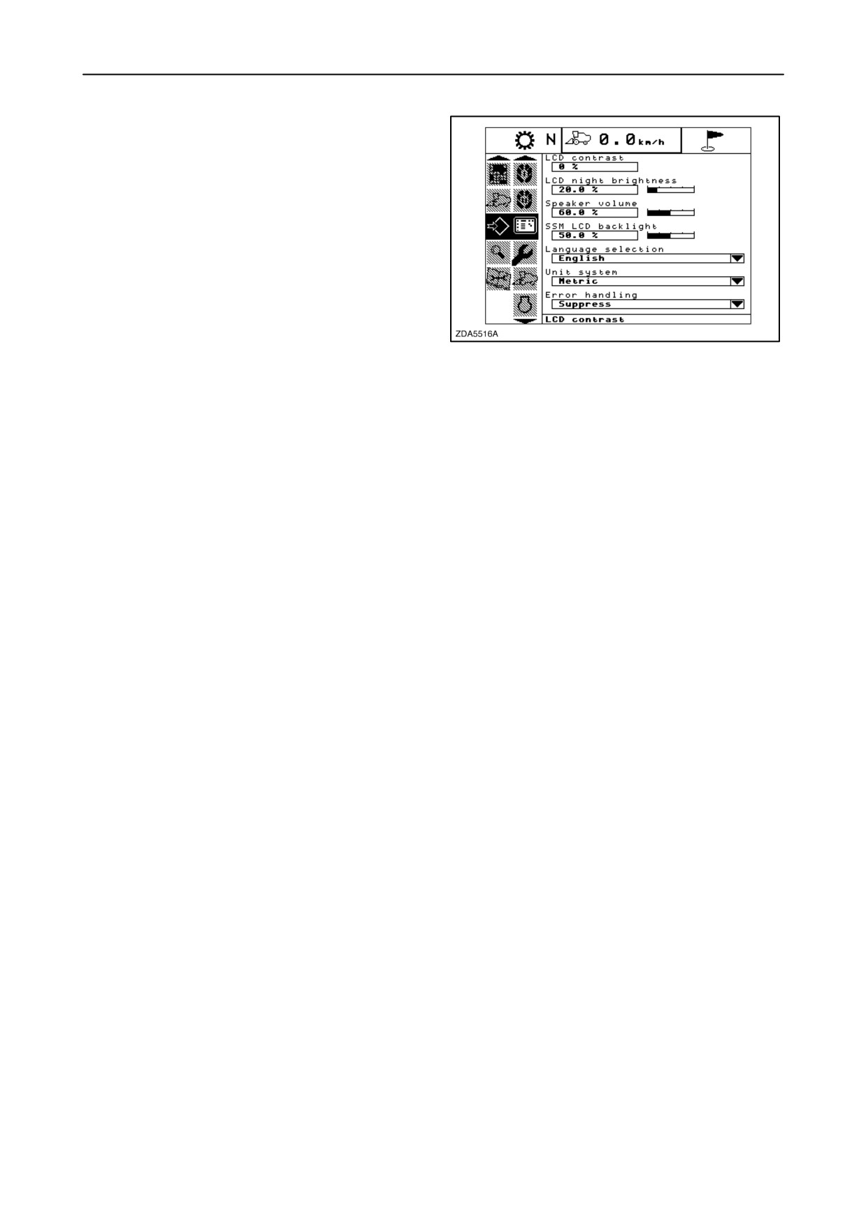
4. Display settings
In this menu the operator will be able change the
display settings.
Proceed as follows:
1. Select the display settings sub menu in the
configuration menu.
2. In the information box, the items appear that can
be changed.
3. Press the ”right” navigation key to enter the
163
information box.
4. Use the ’up” and/or ”down” navigation keys to
select the item to change.
Following items can be changed:
1. LCD Contrast (-50% and +50%)
2. LCD Night Brightness (0 - 100%)
3. Speaker volume (60 -100%)
4. SSM lcd backlight (0 - 100%)
5. Language selection
6. Unit system (Metric, Imperial, US or ISO)
7. Error handling (Show or Suppress)
IMPORTANT: All items mentioned above are factory-
set. When adjusting the LCD contrast or brightness,
make gradual changes. Do not press the enter
button; press the escape button, if the display
becomes unreadable.
The different procedures to change the setting are
explained below.
NOTE: If a setting has been changed but not been
confirmed by pressing the ”enter” key, a message
”Value not stored” will appear on the screen. In this
case, set the item again as explained and confirm by
pressing the ”enter” key.
2-99
SECTION 2 - CONTROLS, INSTRUMENTS AND OPERATION
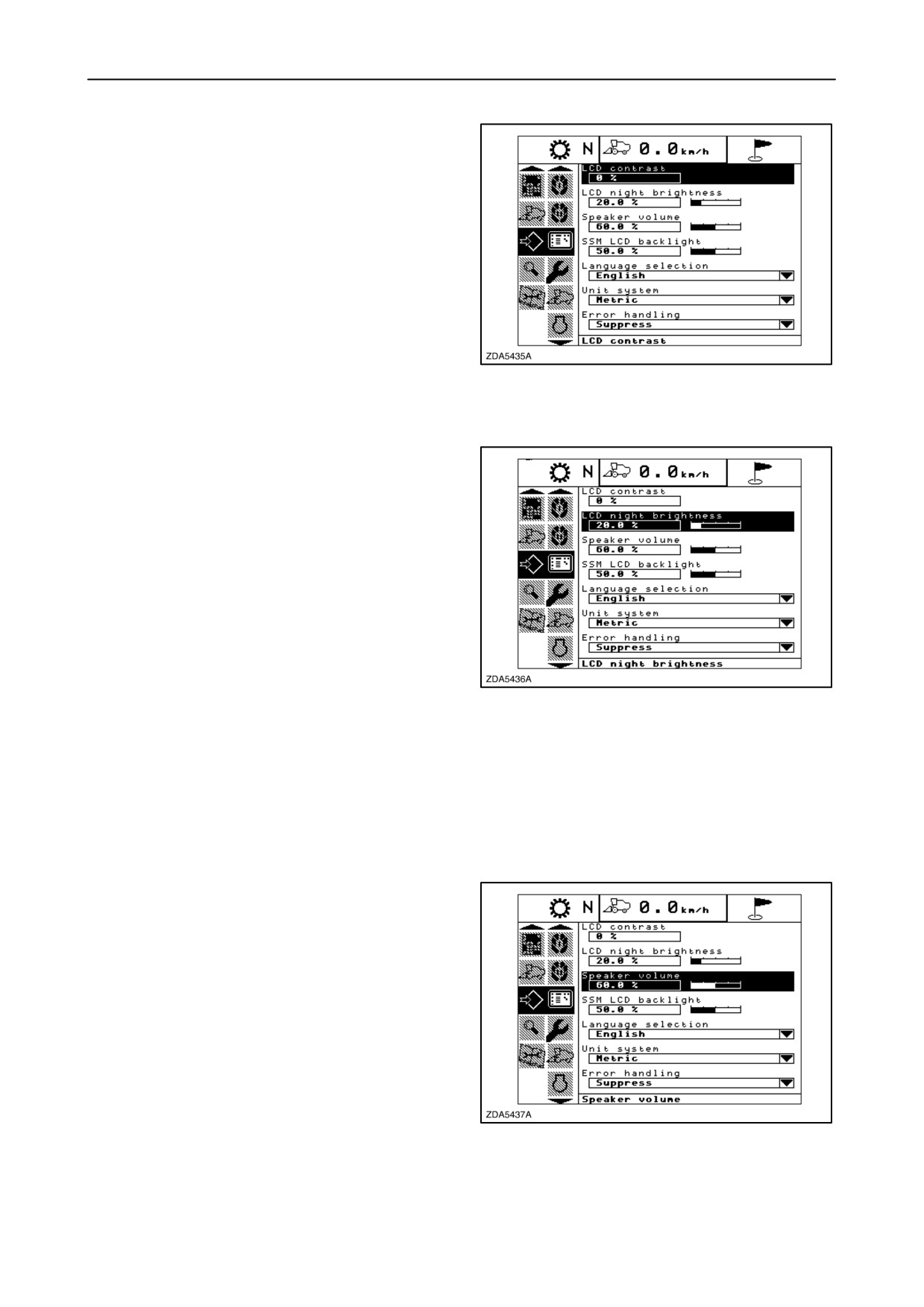
LCD contrast
The LCD contrast can be adjusted between -50%
and +50% in steps of 5%.
1. Select the item “LCD Contrast”.
2. The current contrast level will be highlighted.
3. Change the contrast using the ”+” and/or ”-” key.
NOTE: The contrast level selected will immediately
be applied to the display. This will ease the
determination of the required contrast level.
164
4. Press ”enter” to confirm your choice.
LCD night brightness
In case the operating or road lights are switched on,
the screen brightness
(background lighting) will
automatically be adjusted to the
”LCD Night
Brightness” set value.
The LCD Night Brightness can be adjusted between
0 and 100% in steps of 2%.
1. Select the item ”LCD Night Brightness”.
2. The current brightness level will be highlighted.
165
3. Change the brightness using the ”+” and/or ”-”
key.
NOTE: The brightness level selected will
immediately be applied to the display. This will ease
the determination of the required brightness level.
4. Press ”enter” to confirm your choice.
Speaker volume
The speaker volume can be adjusted between
60% and 100% in steps of 1%.
1. Select the item “Speaker volume”.
2. The current Speaker volume will be highlighted.
3. Change the volume, using the ”+” and/or ”-” key.
4. Press ”enter” to confirm your choice.
166
2-100
SECTION 2 - CONTROLS, INSTRUMENTS AND OPERATION
SSM lcd backlight
The SSM lcd backlight can be adjusted between 0%
and 100% in steps of 2%.
1. Select the item “SSM lcd backlight”.
2. The current backlight level on the SSM will be
highlighted.
3. Change the backlight using the ”+” and/or ”-” key.
4. Press ”enter” to confirm your choice.
167
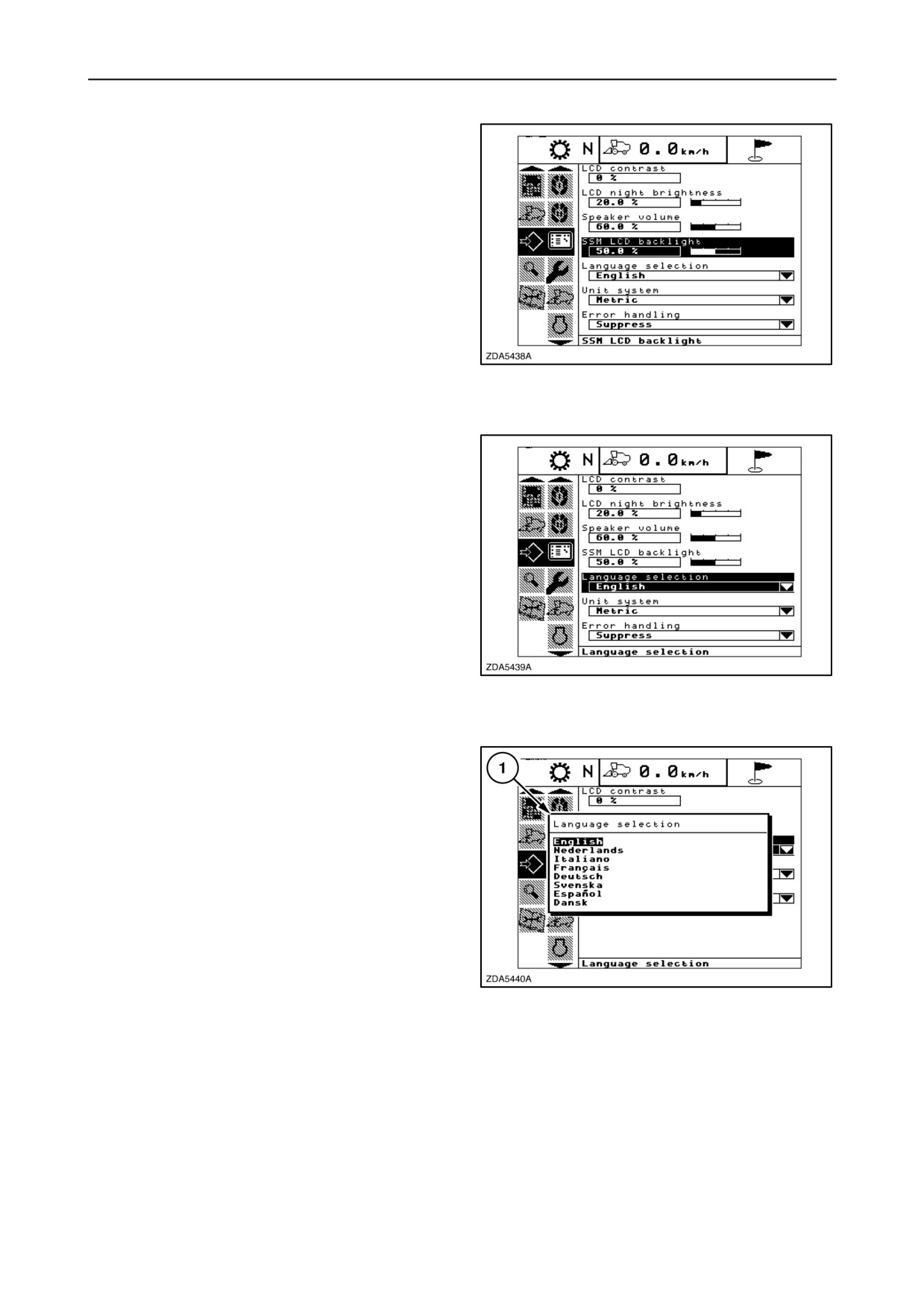
Language selection
Different languages can be selected.
To change the language proceed as follows:
1. Select the item “Language selection”.
2. The current language will be highlighted.
3. Press ”enter”.
168
4. Pop-up screen 1 appears, showing the different
languages.
5. Change the language using the
”up” and/or
”down” navigation keys.
Depending on the destination of the combine, the
languages to select are:
English
Dutch
Italian, etc...
6. Press ”enter” to confirm your choice.
169
2-101
SECTION 2 - CONTROLS, INSTRUMENTS AND OPERATION
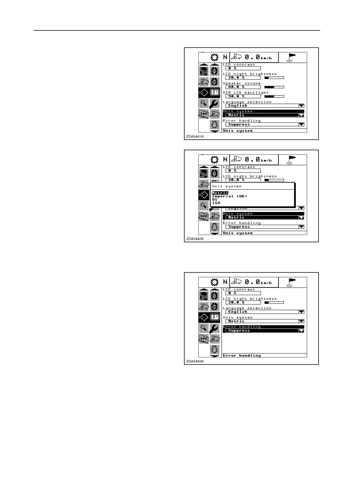
Unit system
Units can be displayed in Metric, Imperial, US or ISO.
To change the unit system proceed as follows:
1. Select the item “Unit System”.
2. The current unit system is highlighted.
3. Press “enter”.
170
4. A pop-up screen appears, showing the different
unit systems.
5. Change the unit system using the ”up” and/or
”down” navigation key.
Possible unit systems are:
- Metric
- Imperial
- US
- ISO
171
6. Press ”enter” to confirm your choice.
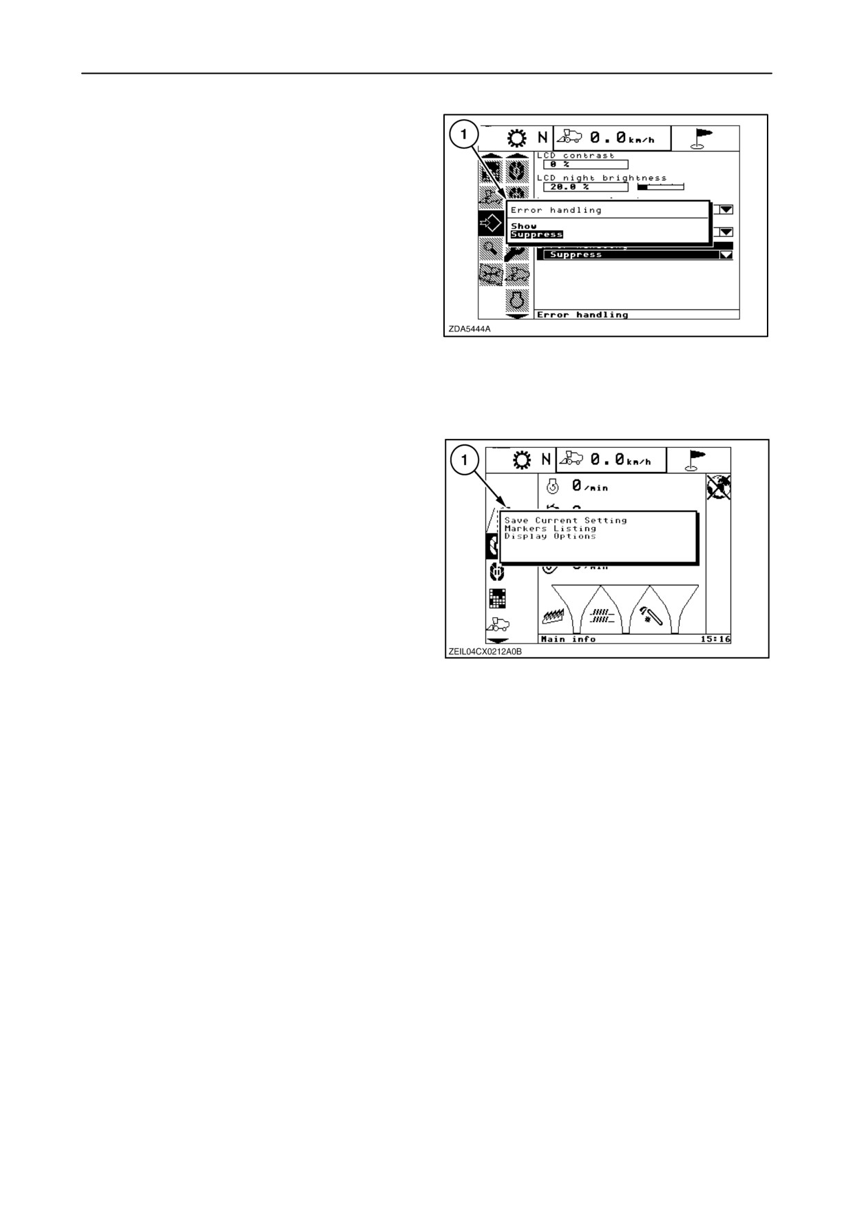
Error handling
System errors can be displayed at the moment they
occur or can be suppressed.
In case ”suppress” has been chosen, a warning
indicator will appear in the indicator bar, but the
error/alarm message window will not appear on the
screen. To read the error/alarm message, select
”active errors” in the configuration sub-menu.
To change the setting, proceed as follows:
1. Select the item ”Error Handling”.
172
2. Press ”enter”.
2-102
SECTION 2 - CONTROLS, INSTRUMENTS AND OPERATION
3. Pop-up screen
1 appears, showing the two
possibilities ”Show” or ”Suppress”.
4. Change the setting using the ”up” and/or ”down”
navigation key.
5. Press ”enter” to confirm your choice.
NOTE: For all these items, it is possible to change the
settings in the Road, Main or Custom info screen if
this items are selected for these screens.
173
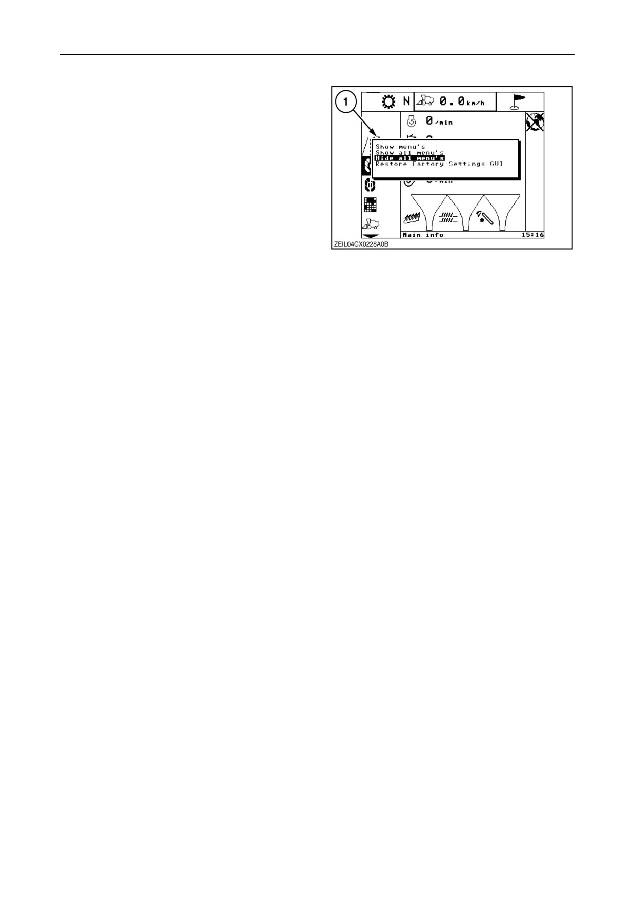
To restore the factory-settings, proceed as follows:
1. Select the “Road info”, “Main info” or “Custom
info” screen and press “enter”.
2. A pop-up 1 screen appears.
3. Select in this list
“Display options”, using the
“down” navigation keys and press “enter”.
174
2-103
SECTION 2 - CONTROLS, INSTRUMENTS AND OPERATION
4. On pop-up screen 1 select “Restore Factory
Settings GUI”, using the “down” navigation key.
5. Press “enter” to become the factory settings of
the following items:
- LCD contrast
- LCD night brightness
- Speaker volume
- SSM lcd backlight
175
- The items mentioned on the “Road info”,
“Main info” and “Custom info” screens.
- Hide all menus (except standard menus)
NOTE: In case someone pressed the “Enter” button
while the screen of the InfoViewt was completely
dark or completely blank, proceed as follows:
1. Set the ignition key OFF.
2. Set the ignition key ON.
3. Press “Enter”.
4. Press four times the “down” navigation key and
press
“Enter” to become again the factory
settings of the “Display settings”.
2-104
SECTION 2 - CONTROLS, INSTRUMENTS AND OPERATION
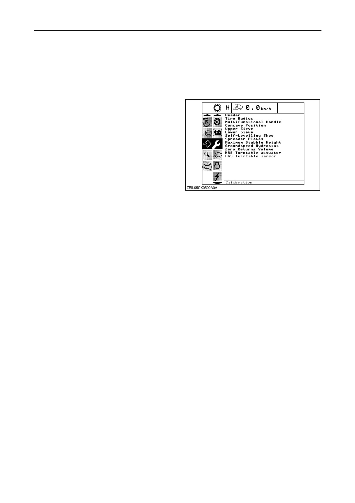
5. Calibration
To obtain a correct read-out on the InfoViewt and
good functioning of the combine, the
electric/electronic system need to be correctly
calibrated.
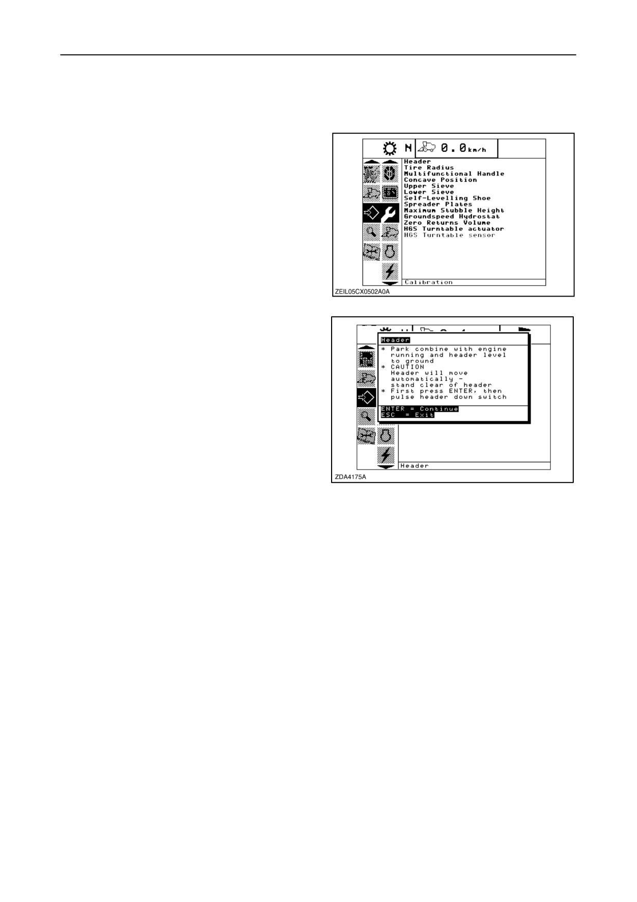
To have an overview of the different calibrations,
select the calibration sub-menu.
Following calibrations can be carried out:
• Header
• Tyre radius (ground speed)
• Multifunction handle
• Concave position
• Upper sieve
• Lower sieve
• Self-levelling shoe
176
• Spreader plates
• Maximum stubble height
• Ground speed hydrostatic
• Zero returns volume
• HGS turntable actuator
(see: “Calibrations for “SmartSteert system)
• HGS turntable sensor
(see: “Calibrations for “SmartSteert system)
2-105
SECTION 2 - CONTROLS, INSTRUMENTS AND OPERATION
CALIBRATIONS FOR BASIC OPERATION
To perform a calibration:
1. Select the calibration sub-menu and press the
’right” navigation key to enter the information box.
2. Use the ”up” and/or ”down” navigation keys to
select the item you want to calibrate.
3. Press ”enter”.
177
4. The calibration window will appear on the screen.
The calibration window has on top the description
of the item to calibrate.
In the middle of the window, a description of the
calibration conditions and procedure will appear.
Follow the steps as described in the window.
The display will automatically show the next step.
Pressing the ”esc” key in one of the following
steps will cause the calibration procedure to stop.
Not reacting to the system within three minutes,
178
will cause the calibration procedure to stop.
Proceed to the end, which is when ”Calibration
succesful” is displayed. Leave the calibration by
pressing the ”enter” or ”esc” key.
2-106
SECTION 2 - CONTROLS, INSTRUMENTS AND OPERATION
Calibration of the Header
DANGER
The header calibration is an automatic process. No
one should be in the area of the header while
calibrating.
Check following conditions before starting the header
calibration procedure:
• The header is attached to the combine.
• Place the combine on level ground, with the
engine running and put the header level to the
ground.
• The engine is running.
• No faults received from the Header Height
Controller (HHC) module.
• Header/ Straw elevator disengaged.
• Lateral floatation buttons NOT pressed.
• The combine is not moving.
• ESC key not pressed.
To calibrate, proceed as follows:
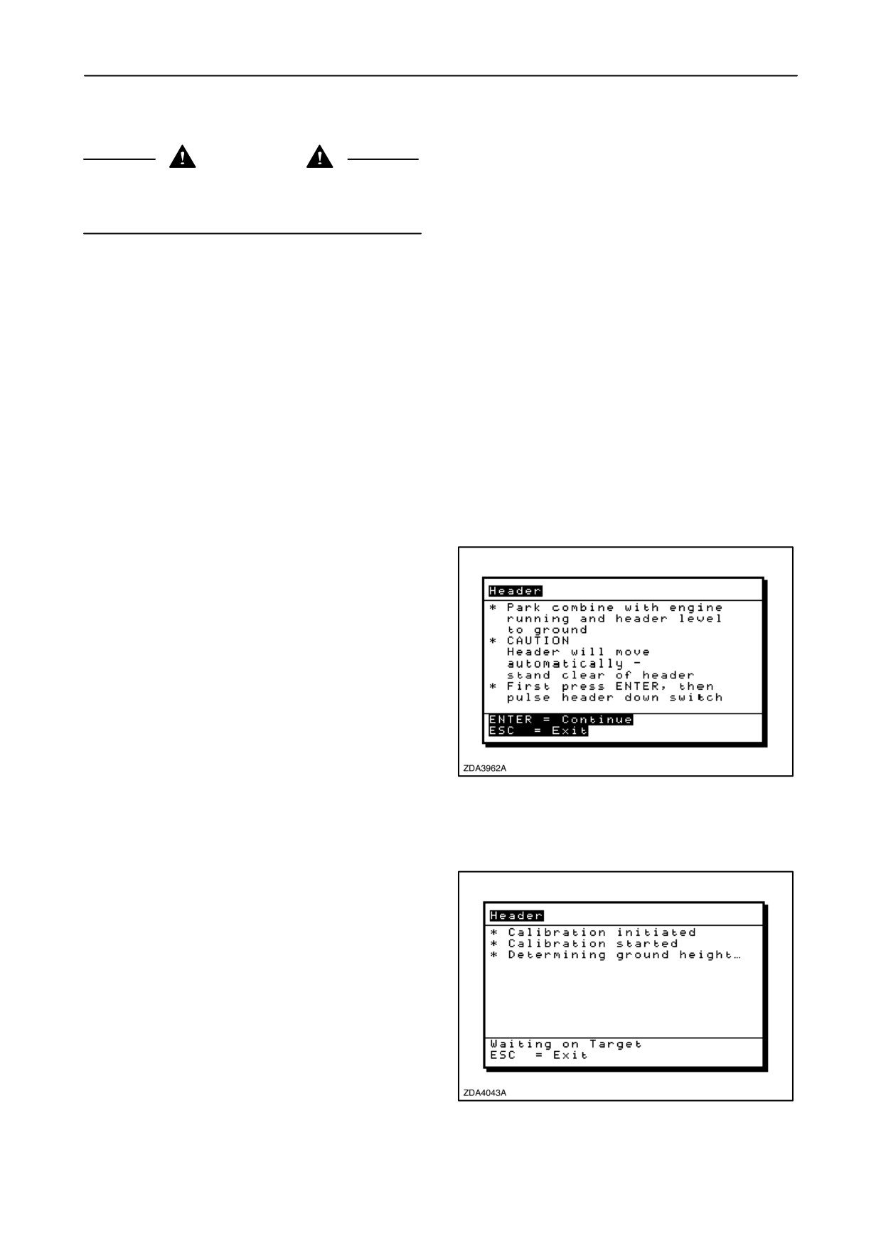
1. Select the ”Header” calibration window.
Message: ”Park the combine with the engine
running and header level to ground”.
Message:
“CAUTION”:
“header will move
automatically - stand clear of header”.
Message: “First press enter, then pulse the
header down switch”.
2. First press enter, then press the header down
key.
179
Attention: The header will lower until it is on the
ground. If the header was already on the ground, it
first raises a little bit.
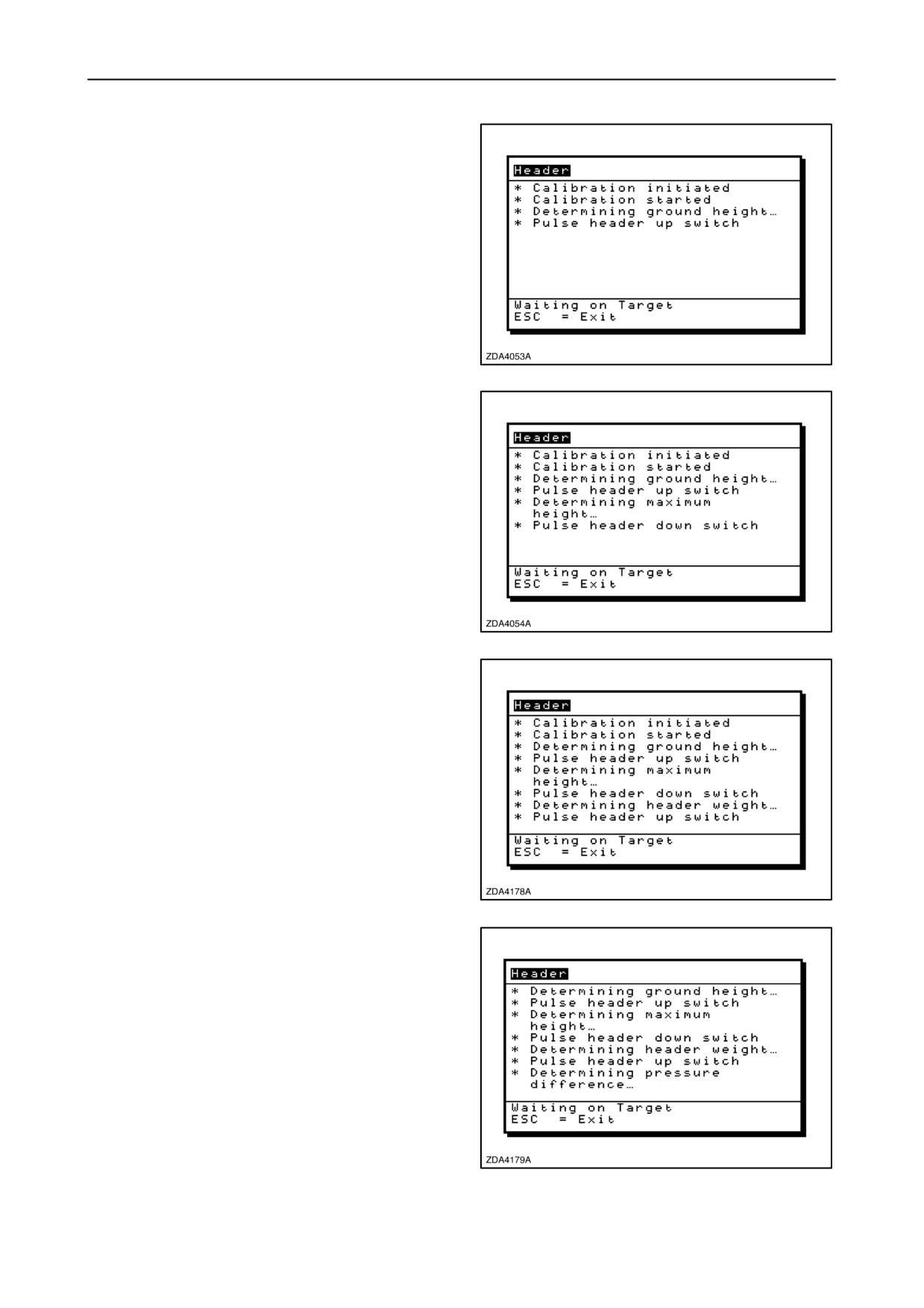
Message: ”Calibration initiated”.
Message: ”Calibration started”.
Message: ”Determining ground height...”.
3. Wait a few seconds until the next message.
180
2-107
SECTION 2 - CONTROLS, INSTRUMENTS AND OPERATION
Message: ”Pulse header up switch”.
4. Press the header up key.
Attention: The header raises slowly to the maximum
calibrated position and moves fast until maximum
position.
181
Message: ”Determining maximum height...”.
5. Wait a few seconds until the next message.
Message: “Pulse header down switch”
6. Press the header down key.
Attention: The header lowers to a position just above
the ground.
182
Message: ”Determining header weight...”.
7. Wait a few seconds until the next message.
Message: “Pulse header up switch”
8. Press the header up key.
183
Message: ”Determining pressure difference...”.
9. Wait a few seconds until the next message.
184
2-108
SECTION 2 - CONTROLS, INSTRUMENTS AND OPERATION
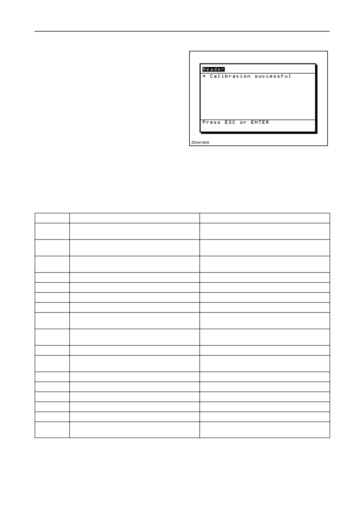
Message: ”Calibration successful“.
10. Press ”Enter” or ”Esc” to close the calibration
window.
185
Remark: If an error occurs while calibrating the
header, the calibration procedure will be aborted and
an error code will appear on the screen.
Error
Possible cause
Remedy
01
Invalid button pressed during calibration
Do not press any other buttons than defined
in the procedure
02
Lateral tilt sensor not in zero position range
Place header flat and check if lateral tilt
sensor is working (if installed)
03
The HHC module did not send a calibration
Check communication with the HHC module
acknowledge after 10 seconds
04
No user interaction for the past 3 minutes
React faster to the calibration procedure
05
User pressed ”escape” key
06
Pressure sensor fault
07
Software got in a faulty state
Restart calibration
08
Autofloatt sensor minimum and maximum
Autofloatt plates hanging loose
position too less difference
09
Straw elevator position not changing
Straw elevator angle sensor stuck at a certain
position
10
Ground speed too high
Do not drive the machine while calibrating
11
Straw elevator angle sensor wrong signal
Check if sensor is well adjusted
(minimum: 2.5V, maximum: 7.5V)
12
HHC module off-line
Make sure HHC module is still functioning
13
Engine rpm lower than 500 rpm
Start engine
14
Straw elevator must be disengaged
Disengage straw elevator
15
Autofloatt left sensor fault
If installed, check sensor
16
Autofloatt right sensor fault
If installed, check sensor
17
Pressure not dropping, increasing in first/
Pressure must be lower/higher than 20/max
second calibration step
P+20 bar
2-109
SECTION 2 - CONTROLS, INSTRUMENTS AND OPERATION
Calibration of the Tyre radius (ground speed)
NOTE: The “Tyre radius” can also be changed in
another sub-menu. Refer to: ”10. Driveline” item
”Tyre radius” of this paragraph.
To calibrate the tyre radius (ground speed), proceed
as follows:
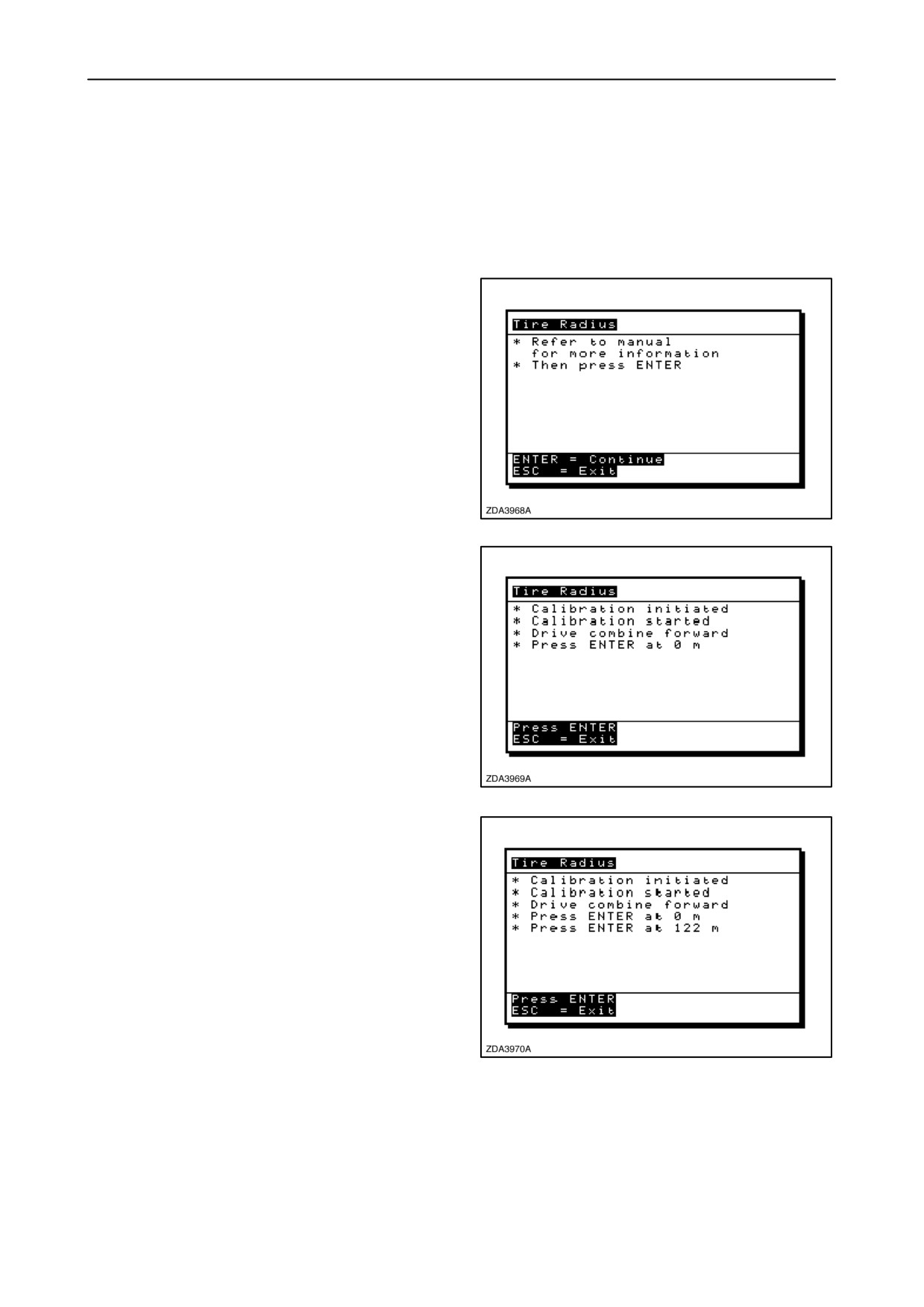
1. Select the ”Tyre Radius” calibration window.
Message:
“Refer to manual for more
information”.
2. Mark a distance of 400 ft or 122 meter to be driven
on a straight road.
Message: “Then press ENTER”.
3. Press “enter”.
186
Message: “Calibration initiated”.
Message: “Calibration started”.
Message: “Drive combine forward”.
Message: “Press ENTER at 0 m”.
4. Start driving the combine and press ”enter” on the
moment the first beacon 0 m (0 ft) is passed.
IMPORTANT: To have a correct calibration, do not
move the multifunction handle between the two
beacons.
187
Message: “Press ENTER at 122 m”.
5. Continue driving the combine and press ”enter”
on the moment the second beacon 122 m (400 ft)
is passed.
188
2-110
SECTION 2 - CONTROLS, INSTRUMENTS AND OPERATION
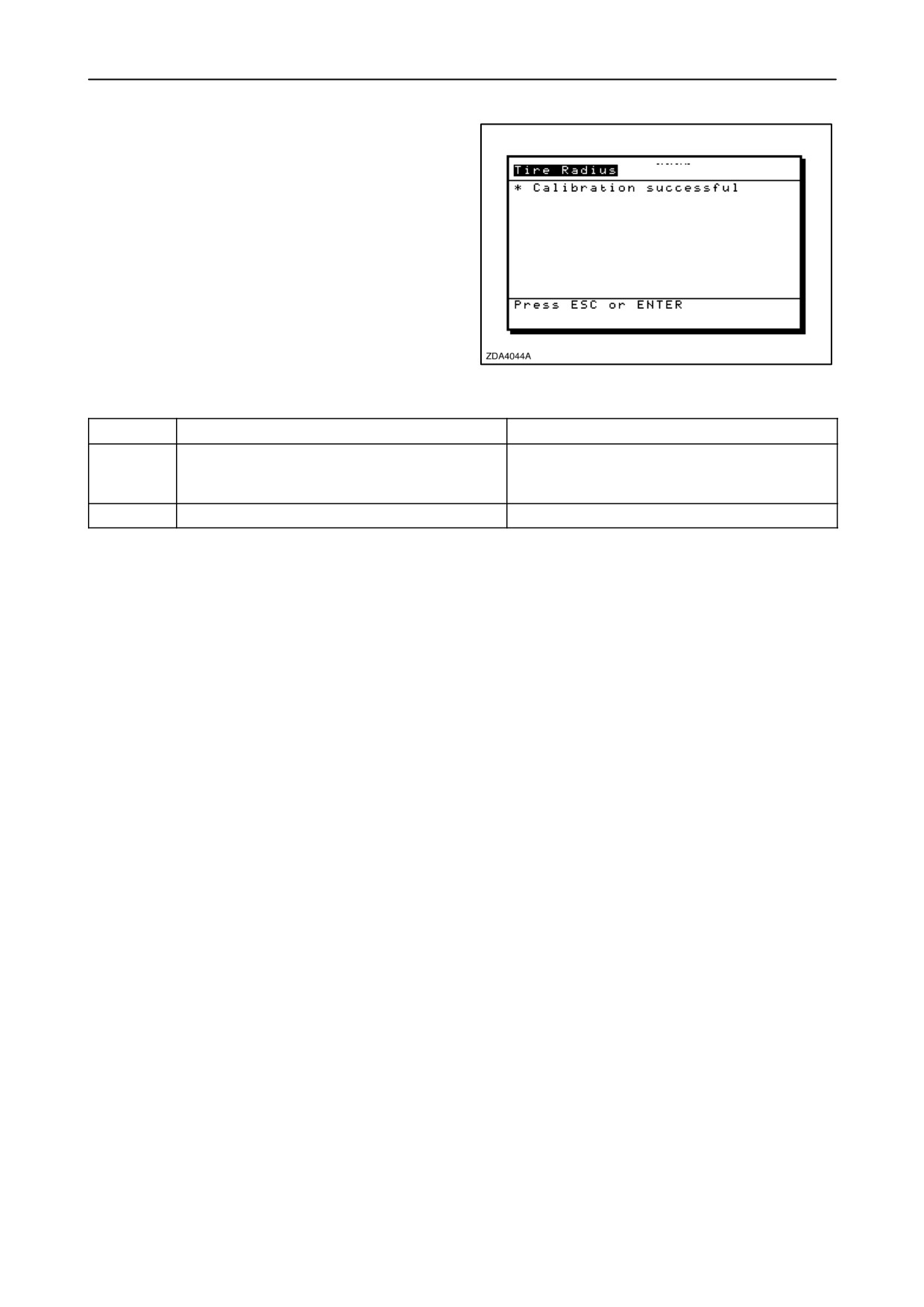
Message: “Calibration successful”.
6. Stop the combine.
7. Press “enter” or “esc” to close the calibration
window.
Remark: If an error occurs while calibrating the tyre
radius, the calibration procedure will be aborted and
an error code will appear on the screen.
189
Error
Possible cause
Remedy
60
The combine was driven the wrong distance
Drive the right distance (122m/400ft), make
or to small/large tyres are installed
sure approximate tyre radius is between 100
and 1500 mm
61
Ground speed sensor giving wrong signal
2-111
SECTION 2 - CONTROLS, INSTRUMENTS AND OPERATION
Calibration of the Multifunction handle
To calibrate the multifunction handle, proceed as
follows:
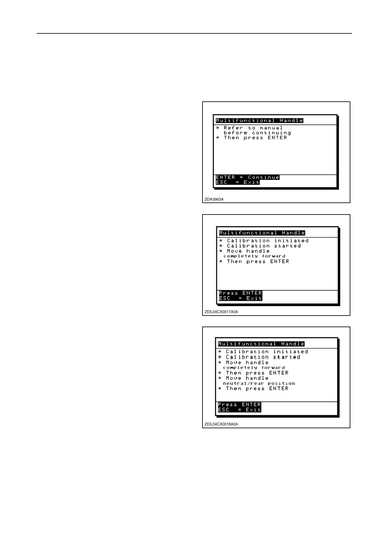
1.
Select the
”Multifunction handle” calibration
window.
Message: “Refer to manual before continuing”.
Message: “Then press enter”.
2.
During this calibration, you will be asked to put the
multifunction handle forward & backward. To
avoid unexpected movement from the machine,
disengage engine & set gear to neutral”.
3.
Press ”enter” to continue or ”esc” to abort the
calibration.
190
Message: “Calibration initiated”.
Message: “Calibration Started”.
Message: “Move handle completely forward”.
Message: “Then press enter”.
4.
Place the multifunction handle in the most
forward position and press ”enter”.
191
Message: ”Move handle to neutral/ rear position”.
Message: “Then press enter”.
5. Place the multifunction handle in the most
neutral/ rear position and press ”enter”.
192
2-112
SECTION 2 - CONTROLS, INSTRUMENTS AND OPERATION
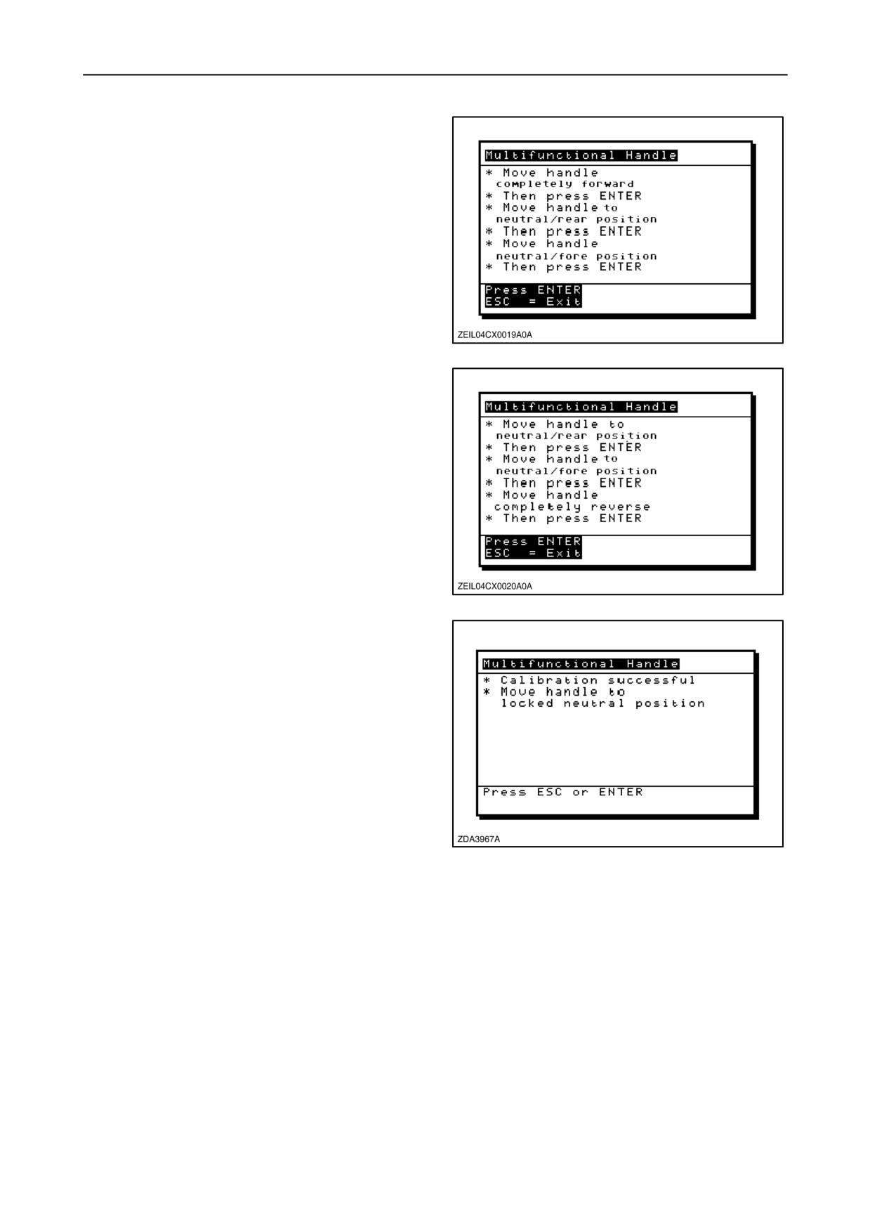
Message: “Move handle to neutral/ fore position”.
Message: “Then press enter”.
6. Place the multifunction handle in the most
neutral/ fore position and press ”enter”.
193
Message: “Move handle completely reverse”.
Message: “Then press enter”.
7. Place the handle in the most rearward position
and press “enter”.
194
Message: “Calibration successful”.
Message:
“Move handle to locked neutral
position”.
8. The calibration is done. Place the multifunction
handle in the locked neutral position and press
”enter” or ”esc” to close the calibration window.
195
2-113
SECTION 2 - CONTROLS, INSTRUMENTS AND OPERATION
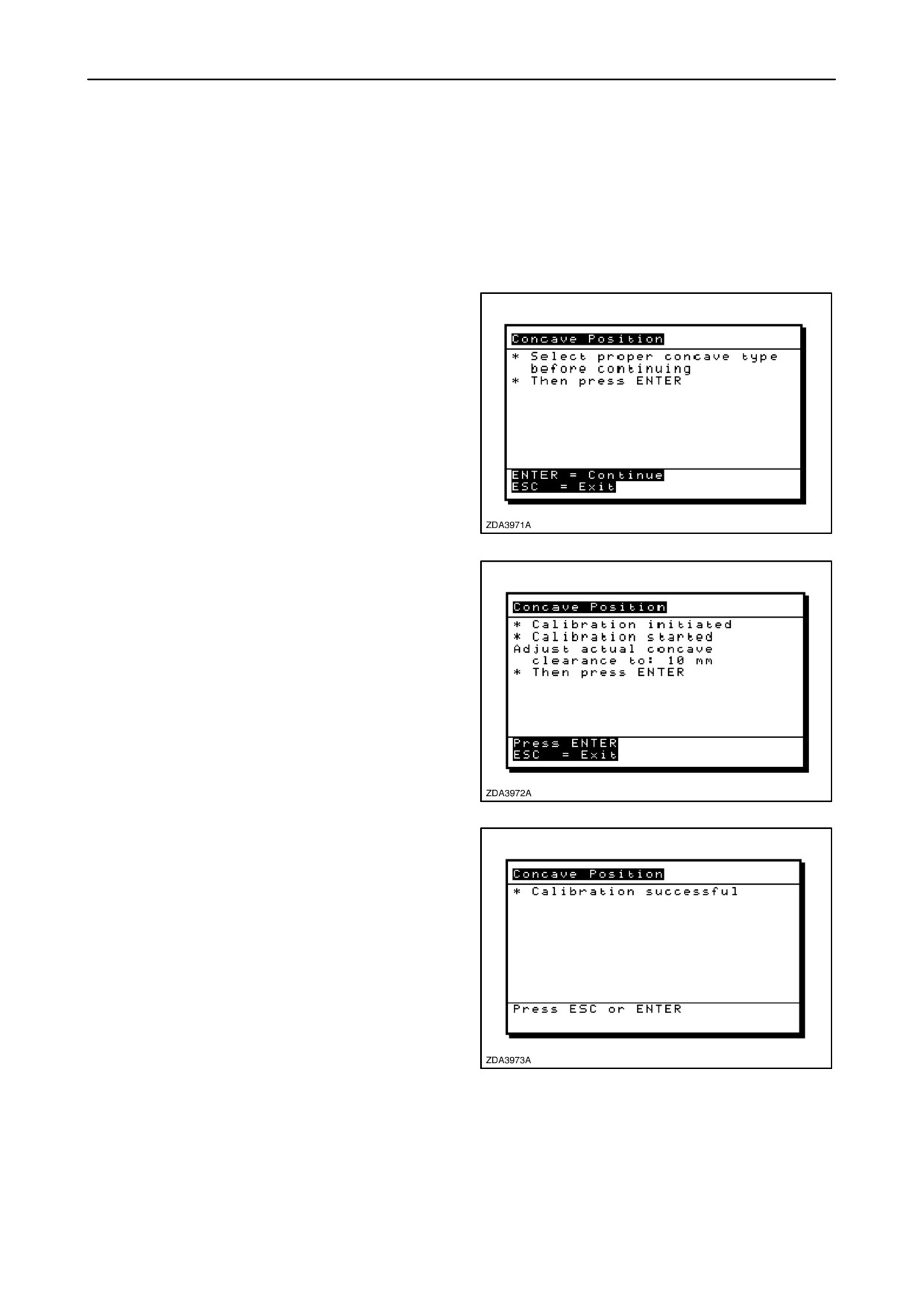
Calibration of the Concave position
To achieve a correct read out of the concave position
on the InfoViewt monitor, after changing or rework
of the concave, a calibration is necessary.
To calibrate the concave position, proceed as follows:
1. Select the ”Concave position” calibration window.
Message: ”Select proper concave type before
continuing”
2. To select the concave type refer to :
“13.Threshing” of this paragraph.
Message: “Then press enter”.
3. Press “enter” to continue or “esc” to close the
calibration window.
196
Message: “Calibration initiated”.
Message:
“Calibration started, adjust actual
concave clearance to: XX mm”.
Message: “Then press enter”.
4. Adjust the concave clearance with the concave
clearance rocker switch to the requested physical
distance and press enter.
Remark: XX mm is 10 mm (3/8”) for a grain concave,
17 mm (43/64”) for a rice concave and
25 mm (15/16”) for a maize concave.
197
Message: ”Calibration successful”.
5. The calibration is done.
6. Press “Enter” or “Esc” to close the calibration
window.
198
2-114
SECTION 2 - CONTROLS, INSTRUMENTS AND OPERATION
Remark: If an error occurs while calibrating the
concave position, the calibration procedure will be
aborted and an error code will appear on the screen.
Error
Possible cause
Remedy
20
Concave opening not correct
Potentiometer giving invalid value, check
opening
21
Concave position sensor error
Check sensor
22
Actuator error
Check with the drum concave clearance
button if the actuator is still moving
2-115
SECTION 2 - CONTROLS, INSTRUMENTS AND OPERATION
Calibration of the Upper sieve
To calibrate the upper sieve, proceed as follows:
1. Check first if the item “Remote upper sieve” is set
to “installed”, refer to headed: “14. Cleaning” of
this paragraph.
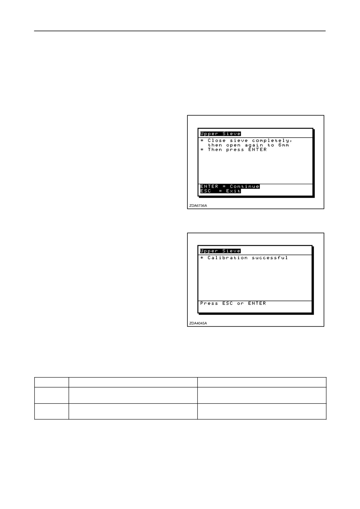
2. Select the “Upper Sieve” calibration window.
Message: “Close sieve completely then open
again to 6 mm (1/4”)”.
Message: “Then press enter”.
3. Close the upper sieve completely using the upper
sieve rocker switch.
Remark: Check if the upper sieve is clean before
closing.
4. Open the upper sieve until the physical distance
measure 6 mm (1/4”).
199
5. Press “Enter” to continue or “esc” to exit the
calibration window.
Message: “Calibration successful”.
6. The calibration is done.
7. Press “Enter” or “esc” to close the calibration
window.
200
Remark: If an error occurs while calibrating the upper
sieve, the calibration procedure will be aborted and
an error code will appear on the screen.
Error
Possible Cause
Remedy
40
Upper sieve position sensor giving wrong
Signal must be minimum 0.25V, maximum 5V
signal
43
Upper sieve opening not 6 mm (1/4”) within
Open sieve to 6 mm (1/4”)
limits
2-116
SECTION 2 - CONTROLS, INSTRUMENTS AND OPERATION
Calibration of the Lower sieve
To calibrate the lower sieve,
1. Check first if the item “Remote lower sieve” is set
to “installed”, refer to headed: “14. Cleaning” of
this paragraph.
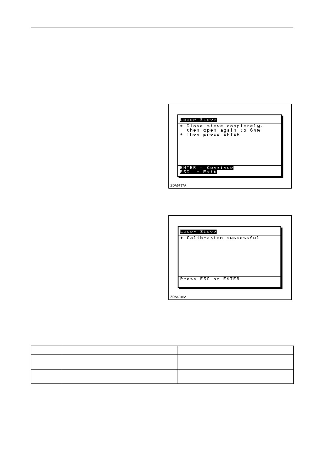
2. Select the “Lower Sieve” calibration window.
Message: “Close sieve completely, then open
again to 6 mm (1/4”)“.
Message: “Then press ENTER”.
3. Close the lower sieve completely using the lower
sieve rocker switch.
Remark: Check if the lower sieve is clean before
closing.
4. Open the lower sieve until the physical distance
measure 6 mm (1/4”).
201
5. Press “Enter” to continue or ”esc” to exit the
calibration window.
Message: “Calibration successful”.
6. The calibration is done.
7. Press “Enter” or “esc” to close the calibration
window.
202
Remark: If an error occurs while calibrating the lower
sieve, the calibration procedure will be aborted and
an error code will appear on the screen.
Error
Possible Cause
Remedy
41
Lower sieve position sensor giving wrong
Signal must be minimum 0.25V, maximum 5V
signal
44
Lower sieve opening not 6 mm (1/4”) within
Open sieve to 6 mm (1/4”)
limits
2-117
SECTION 2 - CONTROLS, INSTRUMENTS AND OPERATION
Calibration of the Self-levelling cleaning shoe
To calibrate the self-levelling shoe, proceed as
follows:
1. Check first if the item “Self-levelling shoe” is set
to “installed”, refer to headed: “13. Threshing” of
this paragraph.
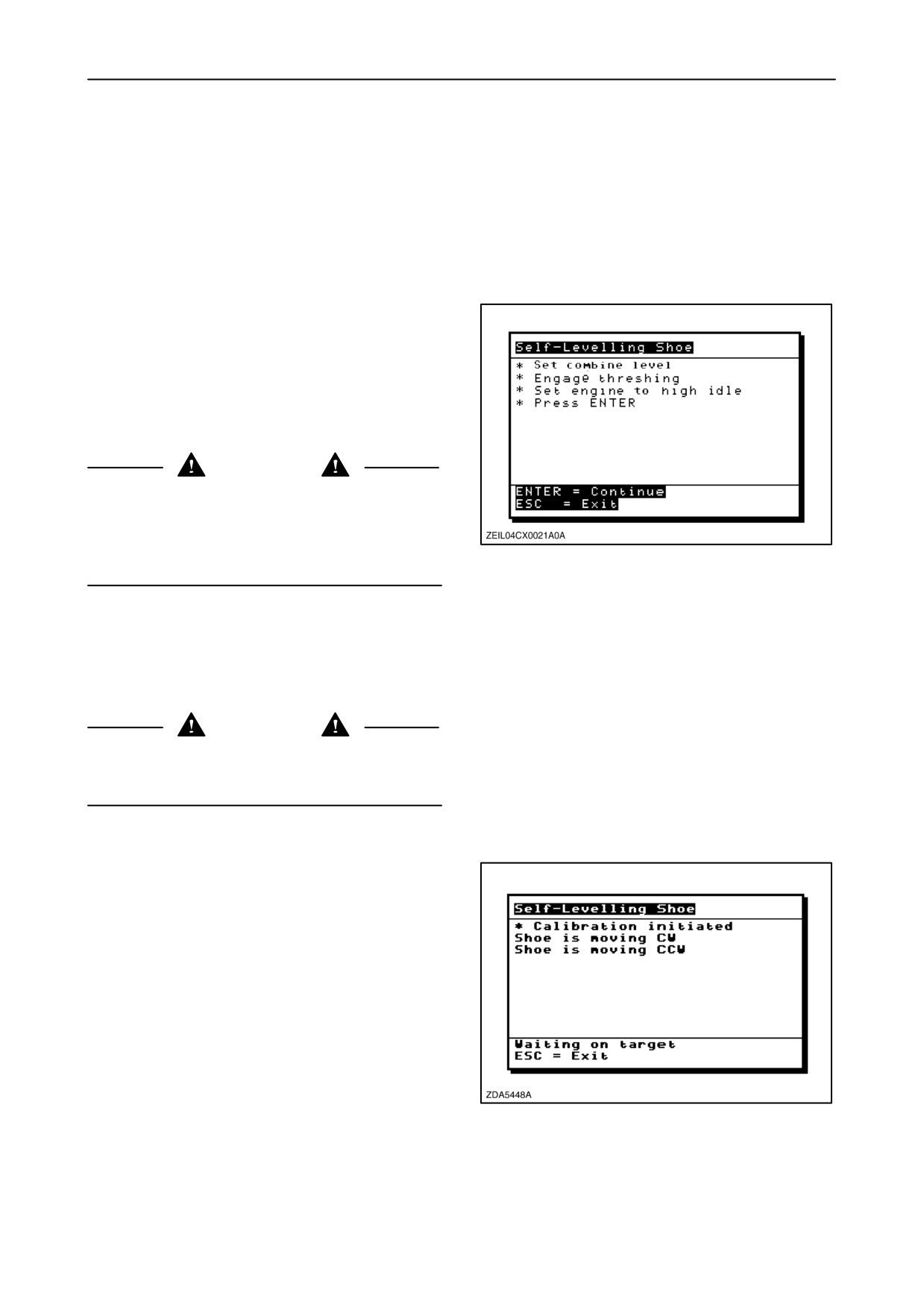
2. Select the
“Self-Levelling Shoe” calibration
window.
Message: “Set combine level”.
Message: “Engage threshing”.
Message: “Set engine to high idle”.
Message: “Press enter”.
CAUTION
Lift the straw elevator to his maximum height, place
the header safety latch over the cylinder rod and stop
the engine before to start the self levelling shoe
203
calibration procedure.
3. Place first a levelling-instrument on the front axle
to check if the combine is parked level.
4. Engage the threshing mechanism and run the
engine at high idle.
DANGER
The self levelling calibration is an automatic process.
No person should be in the moving area of the self
levelling while calibrating.
5. Press the “enter” key to continue or “esc” key to
exit the calibration window.
Message: “Calibration initiated”.
Message: “Shoe is moving CW”.
Message: “Shoe is moving CCW”.
6. The self levelling shoe moves first clockwise and
subsequently counter-clockwise.
204
2-118
SECTION 2 - CONTROLS, INSTRUMENTS AND OPERATION
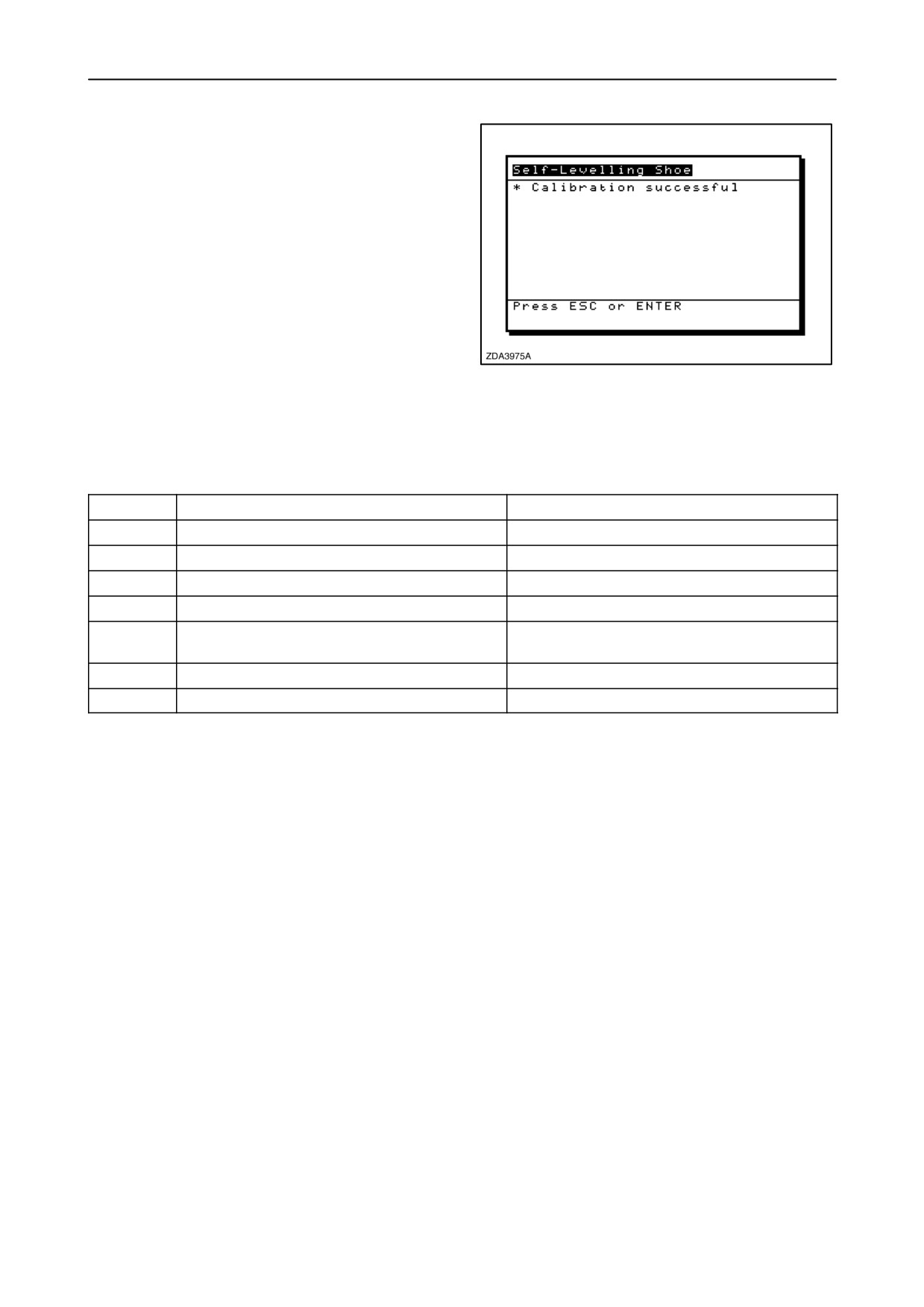
Message: “Calibration successful”.
7. Wait 5 seconds to allow the shoe to come to the
level position.
8. Press ”Enter” or ”Esc” to close the calibration
window.
205
Remark: If an error occurs while calibrating the
self-levelling shoe, the calibration procedure will be
aborted and an error code will appear on the screen.
Error
Possible cause
Remedy
23
Threshing not engaged
Engage threshing
30
Lateral inclination sensor giving wrong signal
Signal must be minimum 0.25V, maximum 5V
31
Shoe position sensor giving wrong signal
Signal must be minimum 0.25V, maximum 5V
32
Option not installed
Select ”Self-levelling shoe” installed
33
Self-levelling cleaning shoe actuator error
Check with diagnostics if actuator is still
moving
34
Combine not level within limits
Put combine more level
54
Engine at low idle
Throttle engine to high idle
2-119
SECTION 2 - CONTROLS, INSTRUMENTS AND OPERATION
Calibration of the Spreader plates
To calibrate the spreader plates, proceed as follows:
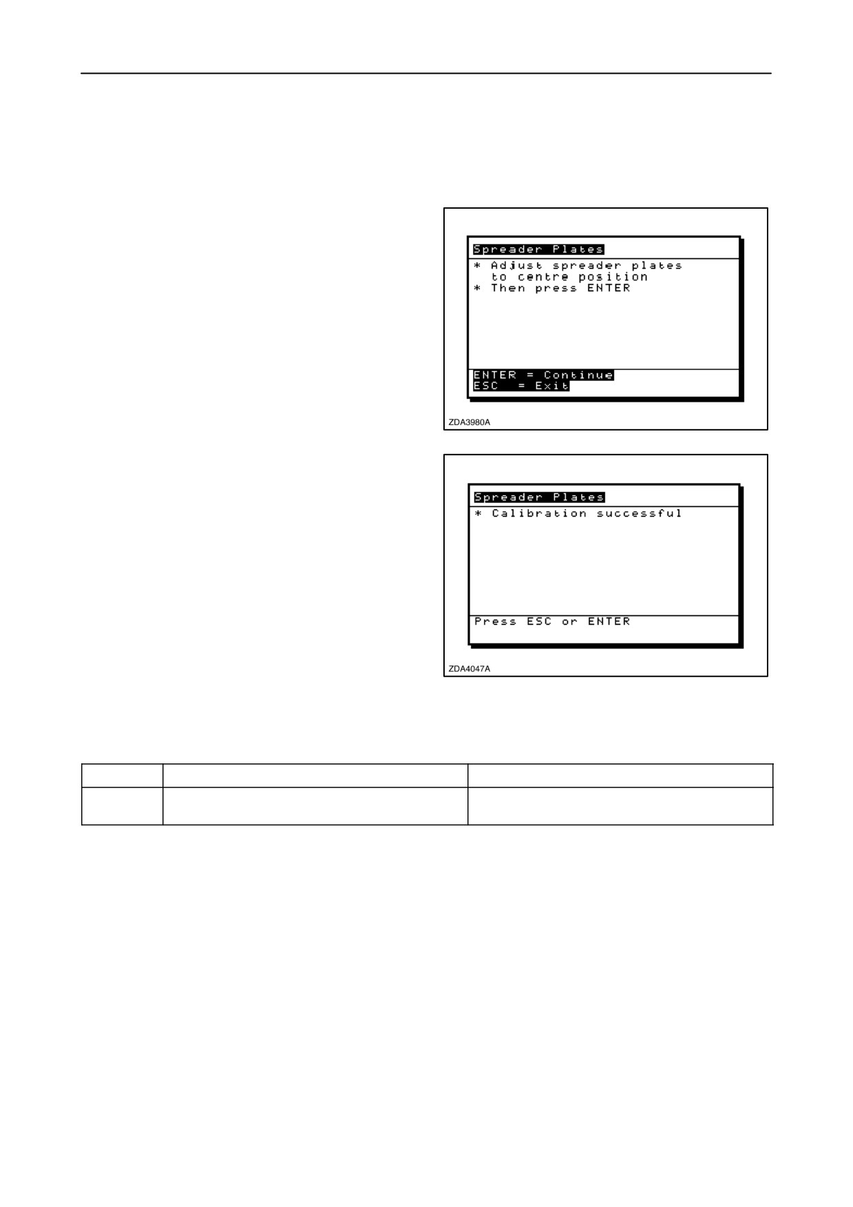
1. Select the “Spreader plates” calibration window.
Message:
“Adjust spreader plates to centre
position”.
Message: “Then press ENTER”.
2. Adjust the spreader plates to the centre position,
using the spreader plates rocker switch.
3. Press “enter” to continue or “esc” to exit the
calibration window.
206
Message: “Calibration successful”.
4. The calibration is done.
5. Press “Enter” or “esc” to close the calibration
window.
Remark: If an error occurs while calibrating the
spreader plates, the calibration procedure will be
aborted and an error code will appear on the screen.
207
Error
Possible cause
Remedy
42
Spreader plate position sensor giving wrong
Signal must be minimum 0.25V, maximum 5V
signal
2-120
SECTION 2 - CONTROLS, INSTRUMENTS AND OPERATION
Calibration of the Maximum stubble height
This is necessary to know from which height the area
counter should stop or start counting. When the
header is raised above this level the area counter
assumes you are not cutting any crop. So you have
to put the header at a certain height you will always
exceed when not cutting crop and always stay below
when cutting crop.
Select the height of the header that corresponds to
the description above.
IMPORTANT: If the value is set too low too few area
may be counted since sometimes the header is
raised above this threshold although the combine is
still cutting.
If the value is set too high the area counter will keep
counting even when the header is raised (but below
this threshold) and the combine is not cutting any crop
any more.
To calibrate the maximum stubble height, proceed as
follows:
1. Select the “Maximum Stubble height” calibration
window.
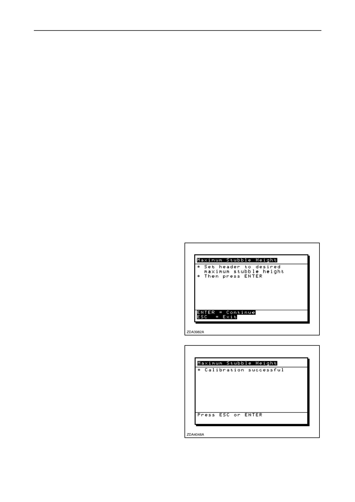
Message:
“Set header to desired maximum
stubble height”.
Message: “Then press enter”.
2. Put the header to the correct position using the
header up or down control switch on the
multifunction handle.
3. Press “enter” to continue or “esc” to exit the
calibration window.
208
Message: “Calibration successful”.
4. The calibration is done.
5. Press “Enter” or “esc” to close the calibration
window.
209
2-121
SECTION 2 - CONTROLS, INSTRUMENTS AND OPERATION
Calibration of the Ground speed hydrostatic
IMPORTANT: Do the calibration of the
”Multifunction handle” before calibrating the
“Ground speed hydrostatic”.
To calibrate the ground speed hydrostatic, proceed
as follows:
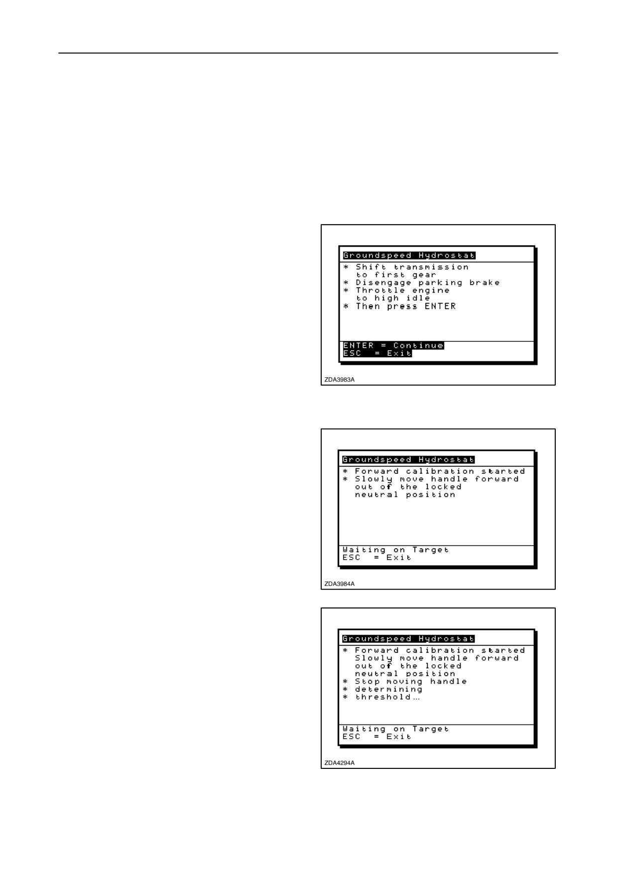
1.
Select the “Ground speed hydrostatic” calibration
window.
Message: “Shift transmission to first gear”.
Message: “Disengage parking brake”.
Message: “Throttle engine to high idle”.
Message: “Then press ENTER”.
2.
Place the multifunction handle in neutral position.
3.
Select the first gear and set the parking brake off.
4.
Set the engine rpm to maximum (2100 rpm).
210
5.
Press “enter” to continue or “esc” to exit the
calibration window.
Message: “Forward calibration started”.
Message: “Slowly move handle forward out of the
locked neutral position”.
6.
Move the multifunction handle from the locked
neutral position slowly forward.
7.
Waiting on target.
211
Message: “Stop moving handle”, “determining”,
“Threshold...”.
8. Stop moving handle and wait until the next
message.
212
2-122
SECTION 2 - CONTROLS, INSTRUMENTS AND OPERATION
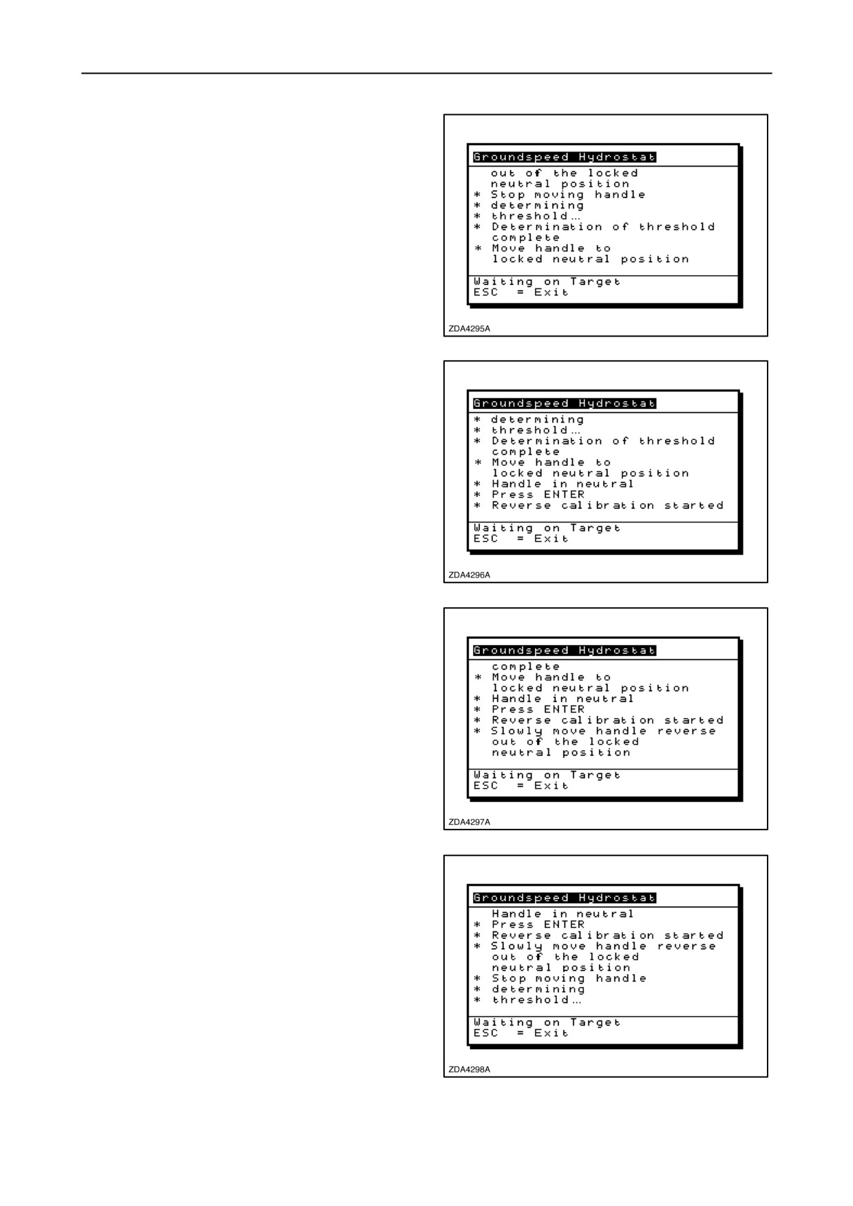
Message:
“Determination of threshold”,
”complete”.
Message:
“Move handle to locked neutral
position”.
9. Move the handle back to the neutral position and
wait until the next message.
213
Message: “Handle in neutral”.
Message: “Press Enter”.
10. Press “enter”.
Message: “Reverse calibration started”.
11. The reverse calibration is started.
214
Message: “Slowly move handle reverse out of the
locked neutral position”.
12. Move the multifunction handle from the locked
neutral position slowly reverse.
13. Waiting on target.
215
Message: “Stop moving handle”, “determining”,
threshold”.
14. Stop moving handle and wait until the next
message.
216
2-123
SECTION 2 - CONTROLS, INSTRUMENTS AND OPERATION
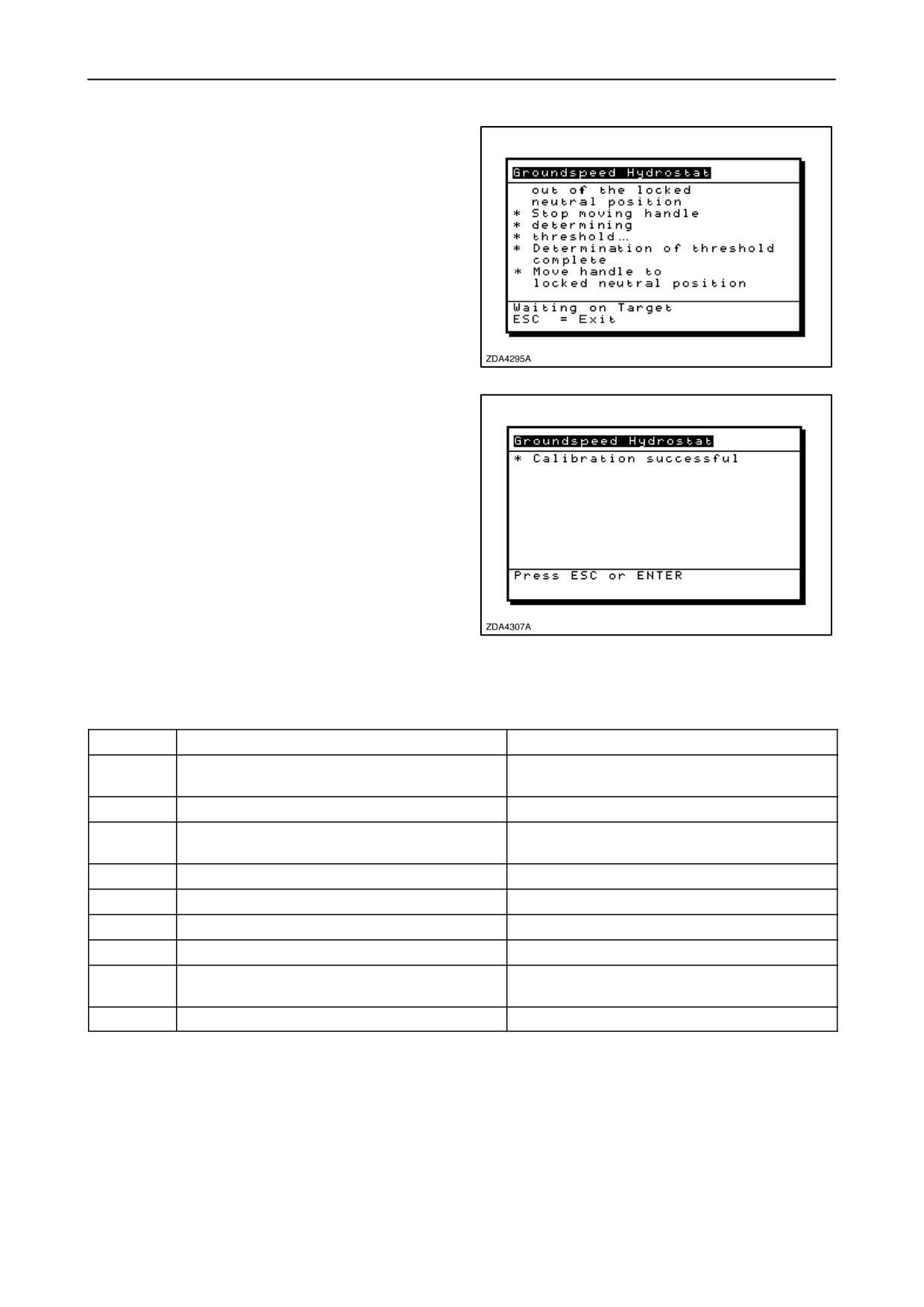
Message:
“Determination of threshold”,
“complete”.
Message:
“Move handle to locked neutral
position”.
15. Move the handle back to the neutral position and
wait until the next message.
217
Message: “Calibration successful”.
16. The calibration is done.
Remark: If an error occurs while calibrating the
ground speed hydrostatic, the calibration procedure
will be aborted and an error code will appear on the
screen.
218
Error
Possible cause
Remedy
50
Handle was pulled back in neutral while
Leave handle at its position
calibrating
51
MFH not calibrated or sensor fault
52
No ground speed pulses were detected after
a period of time
53
Hydrostatic circuit is not working OK
Check for shorts, open wires
54
Engine at low idle
Throttle engine to high idle
55
Transmission not in first gear
Shift transmission to first gear
56
Parking brake was set during calibration
Disengage parking brake
57
No supply voltage seen with handle out of
Check hydro supply voltage and/or neutral
neutral
microswitch for correct operation
58
Movement of the handle is too fast
Move handle slower
2-124
SECTION 2 - CONTROLS, INSTRUMENTS AND OPERATION
Calibration of the Zero returns volume
This calibration has to be carried out:
• At the first start-off.
• Whenever changing the cleaning shoe speed.
• After carrying out repair works to the returns
system.
• After cleaning the returns system
(paddles+ housing)
To calibrate the Zero returns volume, proceed as
follows:
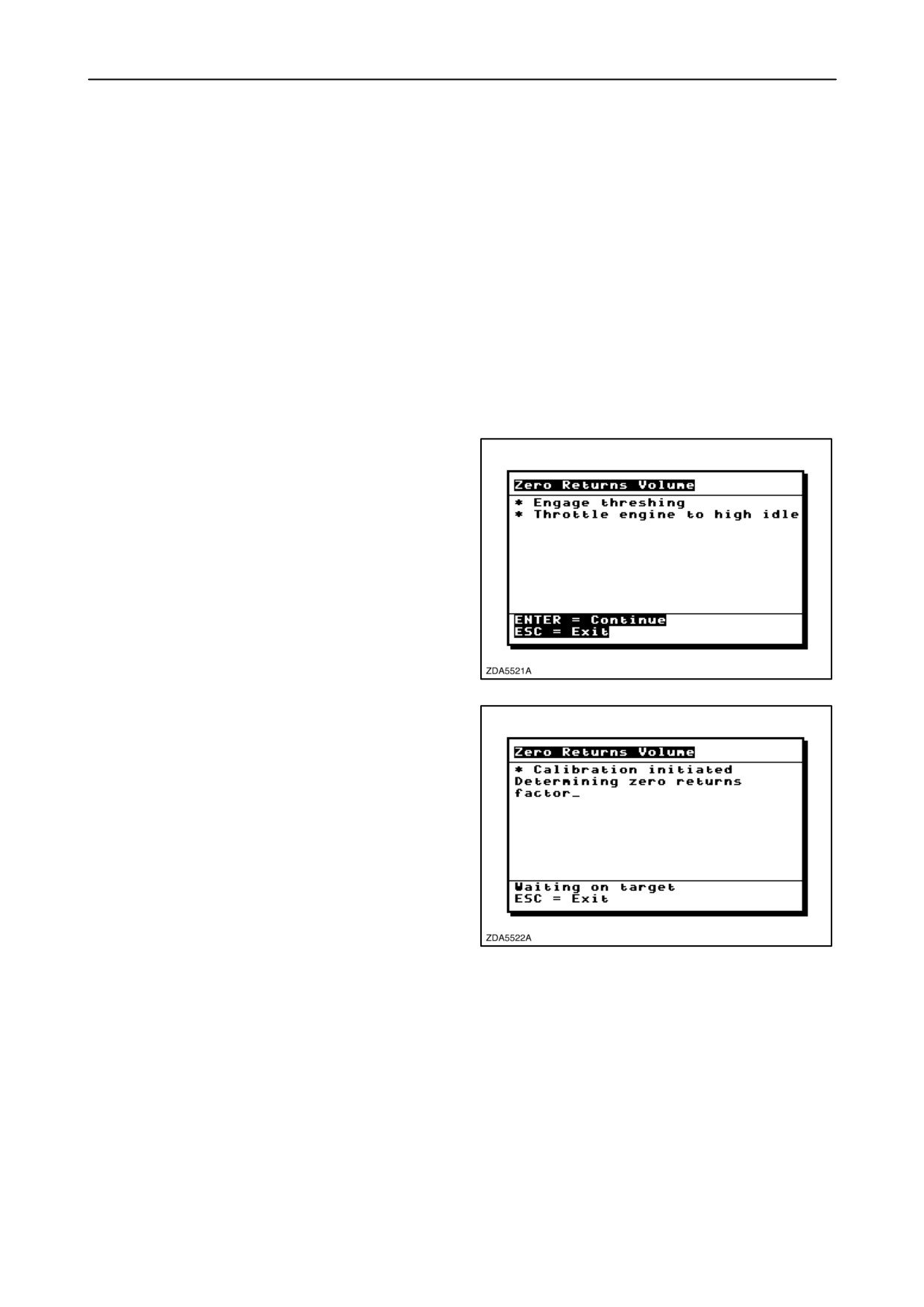
Message: “Engage threshing”
Message: “Throttle engine to high idle”
1. Engage the threshing mechanism and set engine
to high idle.
219
Message: “Calibration initiated
Determining zero returns factor_”
2. Waiting on target.
220
2-125
SECTION 2 - CONTROLS, INSTRUMENTS AND OPERATION
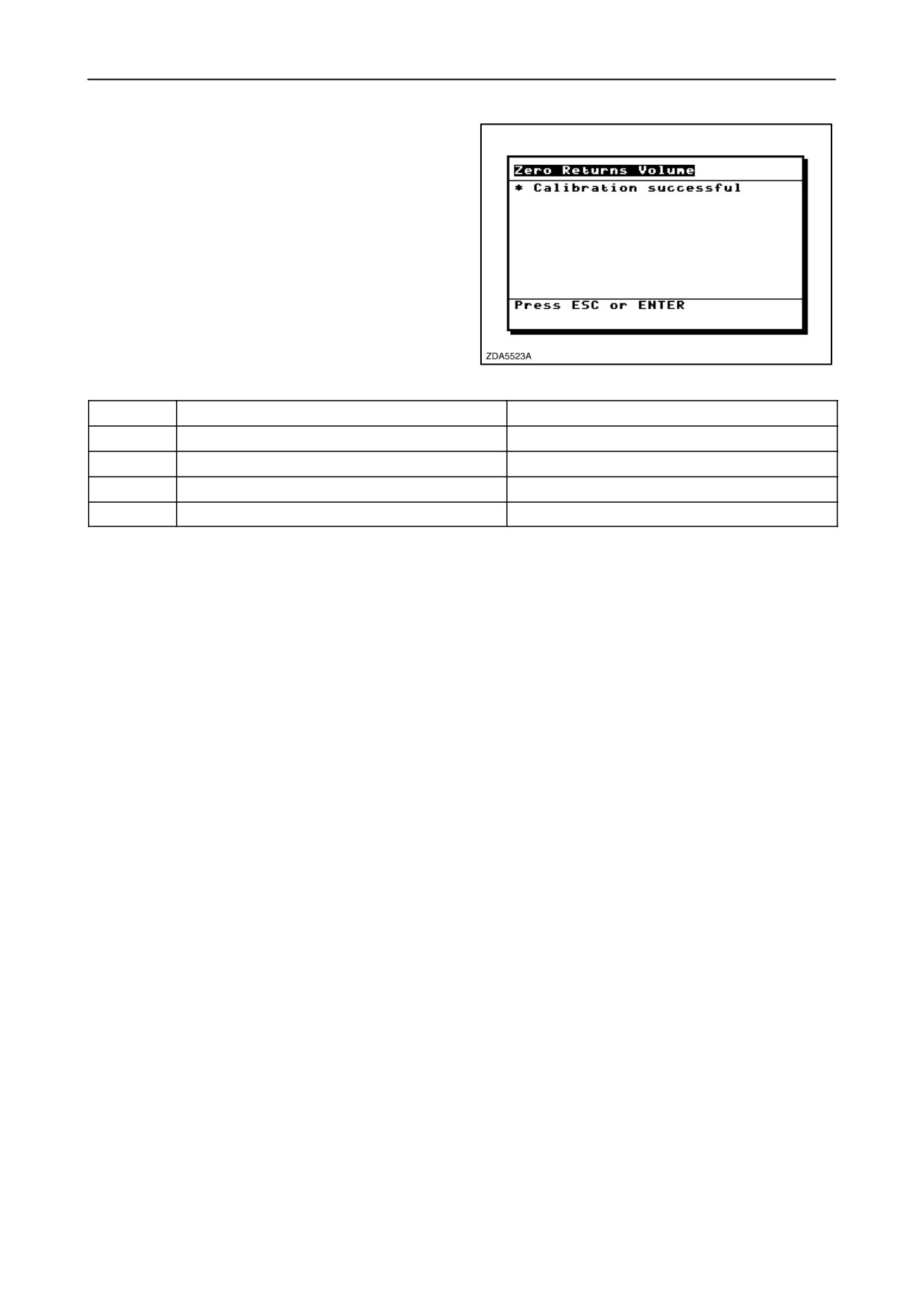
Message: “Calibration successful”
3. The calibration is done.
Remark: If an error occurs while calibrating the zero
returns volume, the calibration procedure will be
aborted and an error code will appear on the screen.
221
Error
Possible cause
Remedy
23
Threshing not engaged
Engage threshing
52
Threshold
Clean pivotable return plate
54
Engine not at high idle
Set engine to high idle
68
No signal
2-126
SECTION 2 - CONTROLS, INSTRUMENTS AND OPERATION
CALIBRATIONS FOR SMARTSTEERt SYSTEM (IF INSTALLED)
The different calibration procedures, in the following
sequence, necessary for good functioning of the
SmartSteert system:
• HGS (Harvester Guidance Sensor)
Turntable actuator calibration
• Straight steer calibration
• Crop edge calibration
• HGS Turntable calibration
IMPORTANT: Check if the following settings are
done to assure correct functioning of the
SmartSteert system.
• Autopilot type: Refer to “VII CONFIGURATIONS
AND CALIBRATIONS“, paragraph headed:
“10.Driveline”
• Longitudinal inclination: Refer to
“VII CONFIGURATIONS AND CALIBRATIONS“,
paragraph headed: “14. Cleaning”
2-127
SECTION 2 - CONTROLS, INSTRUMENTS AND OPERATION
Calibration of the HGS Turntable actuator
NOTE: This calibration should be done only when the
SmartSteert system is installed or when a new HGS
turntable actuator is installed on the combine.
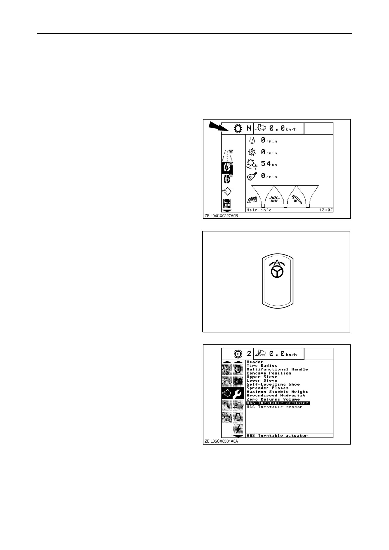
IMPORTANT: Before starting the calibration, make
sure the SmartSteert icon is not shown in the upper
left-hand corner of the InfoViewt monitor.
222
NOTE: If the icon is shown then press onto the
SmartSteert rocker switch once to clear the icon
from the screen.
223
1. If ok, select the calibration sub-menu and press
the “right” navigation key to enter the information
box.
2. Select item “HGS Turntable actuator”, using the
navigation key and press “enter”.
224
2-128
SECTION 2 - CONTROLS, INSTRUMENTS AND OPERATION
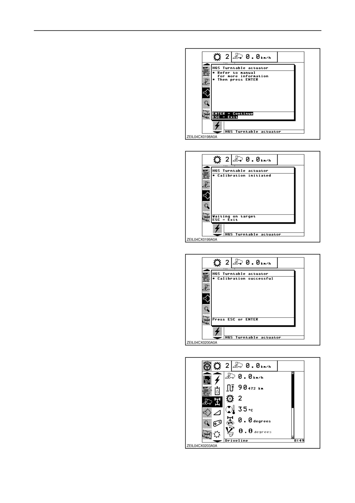
Message: “Refer to manual for more information”
Message: “Then press ENTER”
3. Press “enter” to continue or “esc” to abort the
calibration.
225
Message: “Calibration initiated”
4. The turntable sensor will now be calibrated
automatically. It will turn first to the extreme right
position (CW) and then to the extreme left (CCW)
position, afterwards return to and stop at the
calculated “0 degrees” position.
This is the position where the HGS sensor (2)
(fig. 229) should be looking straight forward in the
driving direction of the combine.
NOTE: This is not the operating position of the
SmartSteert .
226
Message: “Calibration successful”
5. When the InfoViewt monitor indicates that the
calibration has finished successfully, verify that
the HGS sensor 2 (fig. 229) is looking straight
forward.
If not, re-adjust as described in item 8.
227
6. After a successful calibration, the HGS sensor
should look straight forward.
7. The calibration value shown in the “Combine info”
screen, sub-menu “Driveline” should be
0.0 degrees.
228
2-129