New Holland CX720, CX740, CX760, CX780, CX820, CX840, CX860, CX880. Operator's Manual - page 7
SECTION 2 - CONTROLS, INSTRUMENTS AND OPERATION
AUDIBLE ALARM
An audible signal (buzzer) is linked with all the
different levels of alarms (low, medium, high).
A pop-up screen on the Infoviewt shows the
explanation of the specific alarm.
NOTE: When the alarm is functioning, try to locate
the defect or contact your local dealer for assistance.
AUTOMATIC ENGINE SHUT-OFF
In case of an emergency, in order to prevent engine
or hydrostatic system damage, or to protect your
personal safety, the engine will automatically be shut
off immediately, if the following elements occur:
• Low engine oil pressure
(+buzzer alarm + InfoViewt)
• Excessive engine oil and engine coolant
temperature (+buzzer alarm + InfoViewt)
• Low hydrostatic oil pressure
(+buzzer alarm + InfoViewt)
• Engine gearbox oil pressure
(+buzzer alarm + InfoViewt)
NOTE: If it is necessary to move the combine for
safety reasons, the engine can be (re-)started after
an “automatic engine shut-off” (the engine will only be
shut down after 30 seconds in this case). In this case,
the operator assumes the responsibility for any
engine damage or failure.
2-170
SECTION 3 - FIELD AND SITE OPERATION
SECTION 3 - FIELD AND SITE OPERATION
BEFORE DRIVING THE COMBINE
8. Sit down on the operator’s seat and adjust it
according to your weight and size.
1.
Read this Operator’s Manual carefully; especially
the paragraphs headed ”safety precautions” and
9. Adjust the steering wheel to the desired position.
”starting the engine”.
Adjust the rear-view mirrors, if necessary.
2.
Check all chain and belt tensions
10. Start the engine. Refer to the next paragraph
(refer to
“SECTION 4 - LUBRICATION AND
headed ”Starting the engine”.
MAINTENANCE”).
11. Turn the ladder of the operator’ platform in front
3.
Check all the pressures daily. Keep the tyres
of the traction wheel when driving on public roads.
inflated to the pressures given in
“SECTION 8 - SPECIFICATIONS”.
12. Raise the ladder of the engine compartment.
4.
Check the wheel nuts torque daily during the first
week of operation and thereafter on a weekly
13. Ensure the unloading tube is in the closed
basis.
position.
5.
Check the coolant level (ensure the machine is
standing on level ground). Refer to “SECTION 4
14. Disengage the parking brake.
- LUBRICATION AND MAINTENANCE” .
15. Move the throttle switch into the maximum speed.
6.
Check the hydraulic and hydrostatic oil reservoir
level with all hydraulic cylinders retracted and the
16. Raise the straw elevator to its highest position.
header lowered to the ground (machine standing
on level ground). Add oil if necessary. Refer to
“SECTION
4
- LUBRICATION AND
IMPORTANT: To prevent the hydraulic oil from
MAINTENANCE”.
overheating, do not hold the header height control
switch in the operating position longer than is
7.
Lubricate the combine completely as described in
necessary. The same applies to the hydraulic
“SECTION
4
- LUBRICATION AND
controls for the reel height, and the reel fore and after
MAINTENANCE”.
adjustment.
CAUTION
Before driving on the road with a header attached
smaller than 4 meter (foldable grain header or flip-up
maize header), the following actions must be done:
Contact your local dealer.
• Counterweights
• Additional headligths
• Brake pressure limiter valve
3-1
SECTION 3 - FIELD AND SITE OPERATION
STARTING THE ENGINE
Ensure you are thoroughly familiar with the
instruments and controls before starting the engine
for the first time.
To start the engine safely, follow the points as outlined
below.
CAUTION
Before starting the engine, ensure there is enough
ventilation and everyone is standing clear of the
combine.
Daily Start-up procedure
6. Insert the ignition key into the ignition-and-stop
switch and turn the ignition key in the ”contact”
position, check for any alarm or fault messages
Proceed as follows:
on the InfoViewt monitor.
1. Carry out the routine engine service, i.e. check
7. Before starting the engine, warn bystanders by
coolant, oil and fuel tank levels
(refer to
sounding the horn several times.
“SECTION
4
- LUBRICATION AND
MAINTENANCE”). Ensure the battery key is in
8. Start the engine when Pre-Heat lamp below
the ”ON” position.
Ignition key starts to flash. Turn the ignition key
clockwise to engage the starter motor. Engine
wills starts at low idle automatically. (If the engine
2. Make sure the Multi function handle is in neutral
fails to start after 20 seconds, release the ignition
position.
key for about 1 minute before re-engaging the
starter motor).
3. Ensure the road-field mode tumbler switch is in
the road position and the parking brake switch is
9. As soon as the engine starts, release the ignition
in the ON position.
key.
4. Check that the both brake pedals are coupled
10. Check for any engine Alarm/fault messages.
together.
IMPORTANT: Allow the engine to run for one minute
5. Ensure the gearshift selector switch is in the
at low idle before moving off, to ensure adequate
neutral position.
lubrication of the turbocharger bearings.
3-2
SECTION 3 - FIELD AND SITE OPERATION
STOPPING THE ENGINE
Proceed as follows:
1. Move the engine throttle rocker switch to its
bottom position and let the engine run at idling
speed for one minute.
2. Turn the ignition key counter-clockwise to stop
the engine.
3. Remove the key from the ignition-and-stop
switch.
DRIVING THE COMBINE
4. Activate the neutral lock release button (on back
surface of multi function handle) and push
multifunction handle gently forward to drive
forward, or activate neutral lock release button
CAUTION
and pull handle gently backwards for reverse
The combine rear end swings out when changing
driving.
direction. Take care when taking turns.
NOTE: When reversing the combine, an audible
alarm will automatically warn bystanders.
Proceed as follows:
5. Familiarise yourself with the different steering
and driving characteristics.
1. Ensure that the ground speed control lever is in
the neutral position.
WARNING
To prevent runaway of the combine (i.e. when the
ground speed increases during downhill driving and
2. Select a gear by turning the gear select switch in
the desired position. Check sensed gear on the
it is impossible to reduce the speed with the ground
speed control lever), it is necessary to shift into a
InfoViewt
(indicator
bar)
for
proper
lower gear appropriate to the steepness of the hill.
engagement. (this can take a few seconds).
• For field operation, use first, second or third
CAUTION
gear, depending upon the circumstances.
Never drive on public roads with any of the
mechanisms engaged (select road mode with the
road mode selector switch).
• For manoeuvring in confined spaces, use first
gear.
WARNING
• For road transport, use third or fourth gear.
To obtain a smooth speed deceleration when moving
the MFH from forwards driving to neutral a slow down
restrictor is build in, when road mode is selected.
3. Release parking brake (switch in OFF position).
3-3
SECTION 3 - FIELD AND SITE OPERATION
PARKING BRAKE
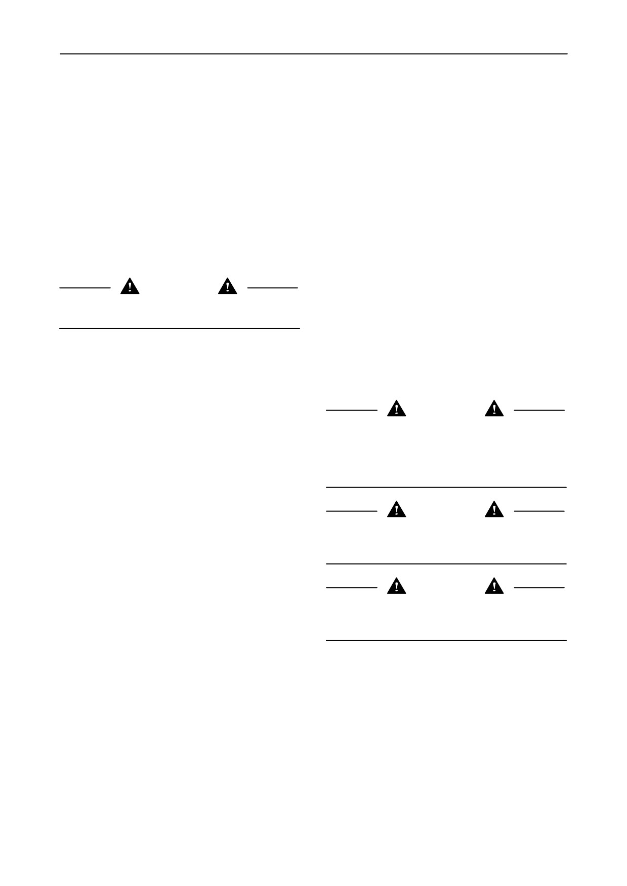
The parking brake is operated by pressing tumbler
switch 1.
The parking brake has two positions.
• The first position: Off position
NOTE: When selecting another gear, the parking
brake is activated automatically during shifting.
• The second position: Parking position
NOTE: Each time the engine is started, the parking
brake will be activated. (even if the parking brake
tumbler switch is set in the “OFF” position) To release
1
the parking brake, set the parking brake tumbler
switch first in the “ON” position after in the “OFF”
position.
NOTE: When the “ON” (parking) position is selected
during driving, the parking brake will be activated
when the multifunction handle (hydrostatic) is moved
to neutral position or the ground speed is lower than
0.5 km/h (0.3 mph).
Emergency stop (If configured in InfoViewt
)
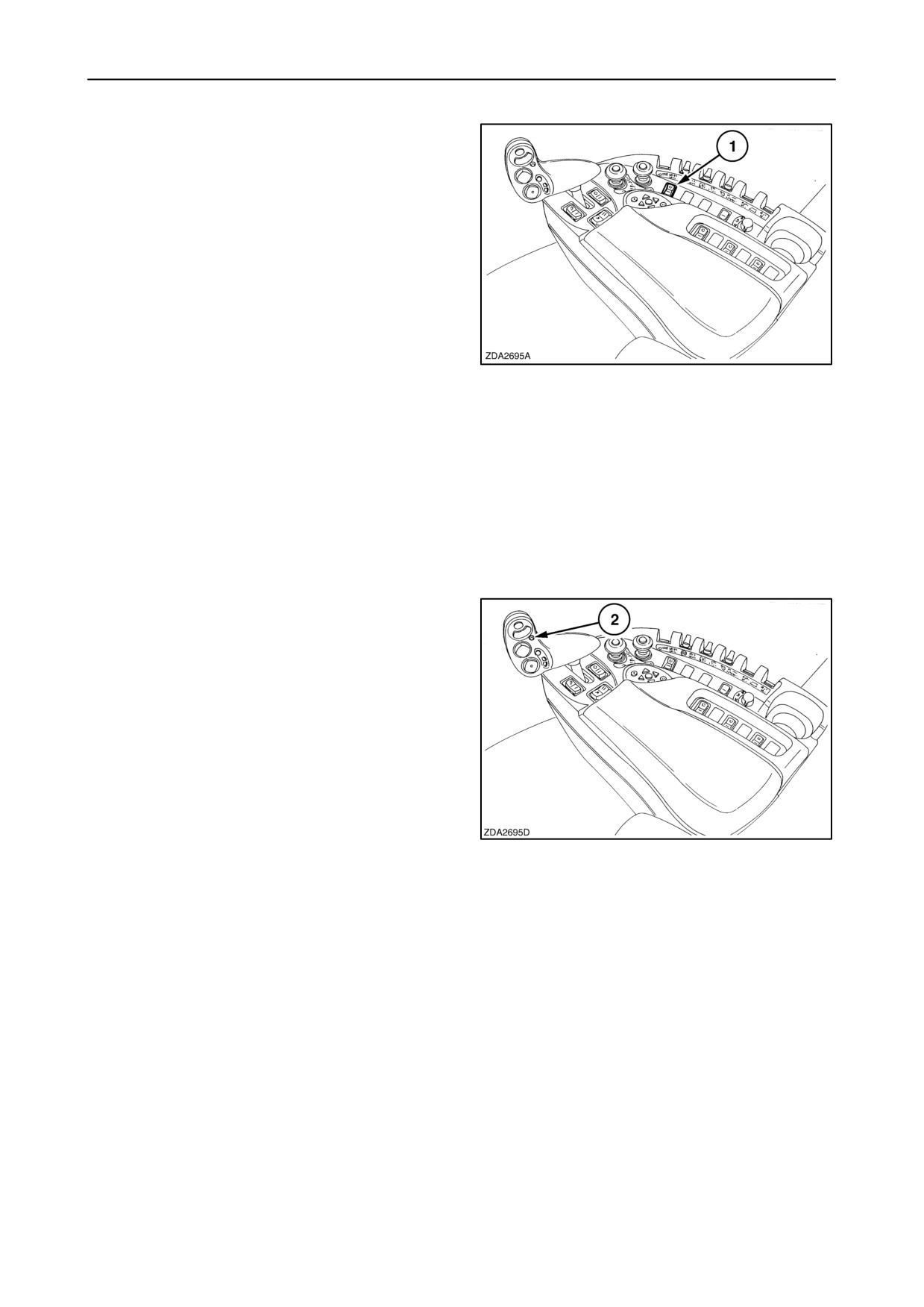
Pressing quick stop button 2 on the multifunction
handle while driving the combine will cause the
combine to stop.
Depending on the time button 2 is pressed, the
combine will stop like explained below:
• If pressing not longer than two seconds on
quick stop button 2:
The hydrostatic will be disabled immediately.
• If pressing between two and six seconds on
quick stop button 2:
The hydrostatic will be disabled immediately.
2
After two seconds the parking brake will
come on additional, during four seconds.
• If pressing for a minimum of six seconds on
quick stop button 2:
The same result will occur when pressing
between two and six seconds, but after six
seconds the parking brake will close
completely to stop the combine abruptly.
Remark: After an emergency stop, to advance again,
bring first the multifunction handle back to the neutral
position (the parking will be released automatically).
3-4
SECTION 3 - FIELD AND SITE OPERATION
Gear shifting system
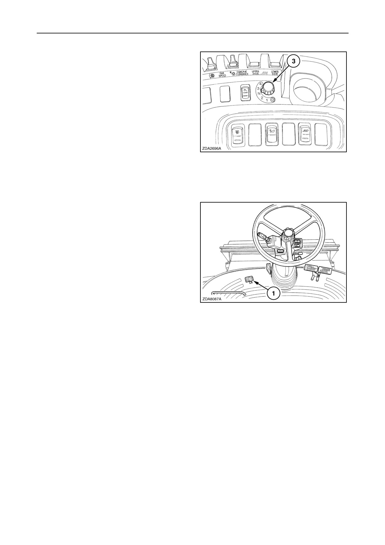
A selector switch
3
(1-2-N-3-4) indicates the
selected gear.
Selecting a gear is only possible with the
multifunction handle in neutral position.
Turn the button to select a gear. The parking brake is
automatically engaged and the hydrostatic system
will be disabled.
The InfoViewt shows the selected gear on top of the
screen when the gearshifting is completed. The
parking brake will reset to its previous state and the
operator can take over the hydrostatic control.
3
Remark: When selecting another gear during driving,
the system will wait until the multifunction handle is in
the neutral position and the combine is stopped
completely.
Differential lock (if equipped)
When operating in slippery or muddy ground
conditions the differential lock may be engaged to
provide better traction.
If one of the traction wheels start spinning,
immediately depress the differential lock pedal (1).
Now both traction wheels will turn at the same speed.
Keep the pedal (1) depressed until the machine has
passed the obstacle.
4
Release the pedal to disengage the differential lock.
IMPORTANT:
• Do not make turns with differential lock pedal
depressed.
• It may be necessary to slow down the combine to
allow engagement of the differential lock.
3-5
SECTION 3 - FIELD AND SITE OPERATION
HARVESTING
Description of operation
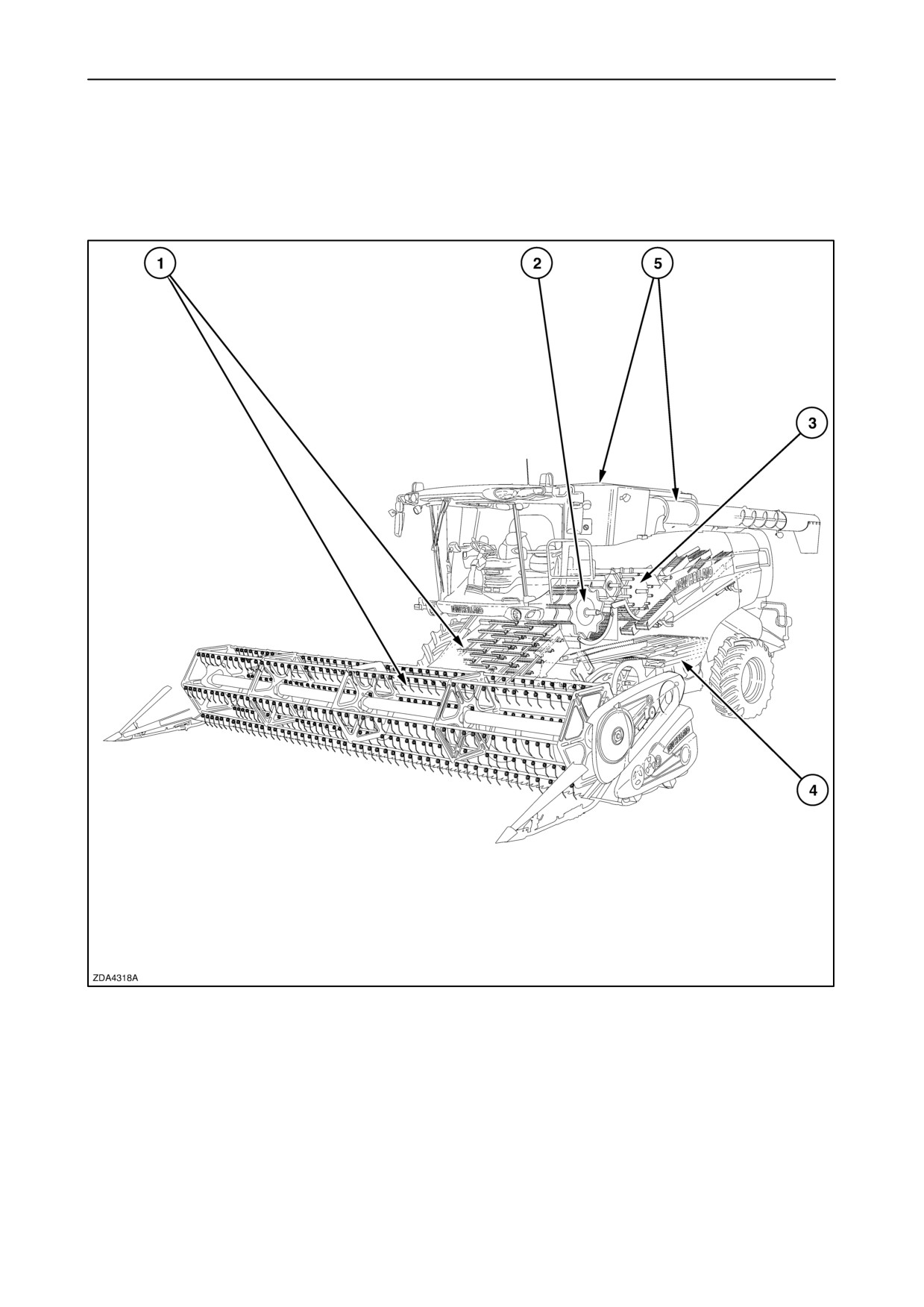
The combine harvester performs five basic functions:
5
1. Feeding
2. Threshing
3. Separation
4. Cleaning
5. Grain storage and unloading
3-6
SECTION 3 - FIELD AND SITE OPERATION
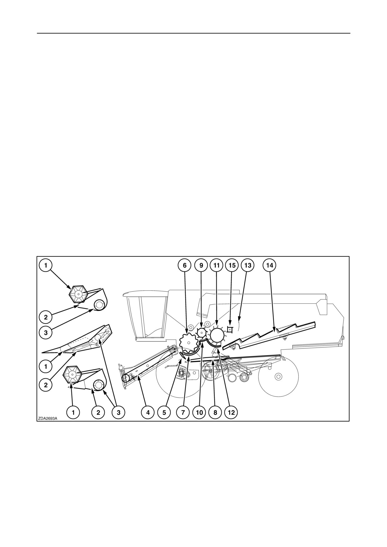
1. Feeding
2. Threshing
The reel 1 (on the grain or flex header) or the
As the drum 6 rotates, it rubs the crop against the bars
gathering chain (on the maize header) feeds the
of concave
7. This rubbing action separates
crop/cobs into the header 2 towards the auger 3. The
approximately 90% of the grain from the straw.
auger 3 feeds the crop into the front of the straw
elevator 4.
• Clean grain falls onto the grain pan 8.
The straw elevator head pivots on the elevator frame
which enables the header to follow deviations in slope
• Straw (and little grain) are guided to the beater 9.
up to 3_ on either side, relative to the base unit
position.
De-awning plates on small grain concaves can be
swung up underneath the concave to increase the
The crop is then carried up the straw elevator where
rubbing action when threshing winter barley or
it is fed over the stone trap 5 into the drum and
difficult-to-thresh crops.
concave area. At this point the feeding is complete
and the threshing starts.
Rasp bars (de-awning slats) can be installed on the
The stone trap 5 is designed to trap stones and other
front part of the concave to improve the threshing
foreign objects which may cause damage to internal
efficiency (especially important in wheat) and to avoid
parts of the combine.
white caps.
6
3-7
SECTION 3 - FIELD AND SITE OPERATION
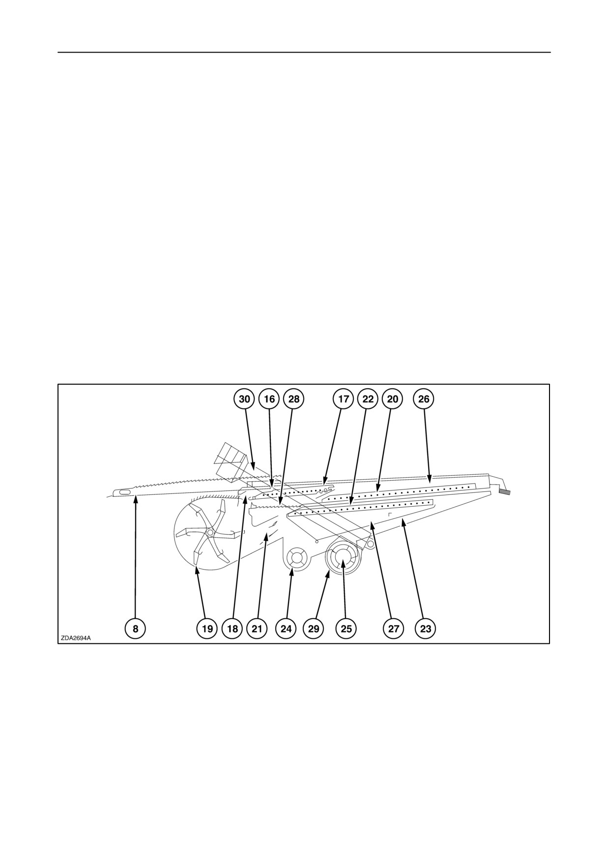
3. Separation
4. Cleaning
The beater 9, with beater concave 10, strips the straw
from the drum and guides it to rotary separator 11 and
concave 12, which further separates the grain from
The grain and chaff on the grain pan 8 are transported
the straw.
to the rear by the reciprocating action of the cleaning
shoe. On units with self-levelling cleaning shoe, an
electrical actuator ensures that the cleaning shoe
The straw retarding curtain 13 prevents the rotary
automatically remains horizontal in the transverse
separator from throwing the straw too far onto the
axis of the machine, even when operating on side
straw walkers 14.
slopes up to 17%. This innovation increases the
capacity of the cleaning shoe considerably when
A straw flow beater 15 is standard installed to improve
operating in hilly conditions.
the straw transport towards the straw walkers and to
enable a smoother flow of material in heavy crop
conditions.
The straw walkers 14 oscillate, lift and tumble the
If the cleaning shoe is not self levelling (fixed cleaning
straw, permitting the remaining grain to fall through
shoe), operation on slight slopes is made possible by
the walkers and slide down the walkers return chutes
the installation of hillside dividers on the pre-sieve
onto the rear of grain pan 8.
and the upper sieve.
7
3-8
SECTION 3 - FIELD AND SITE OPERATION
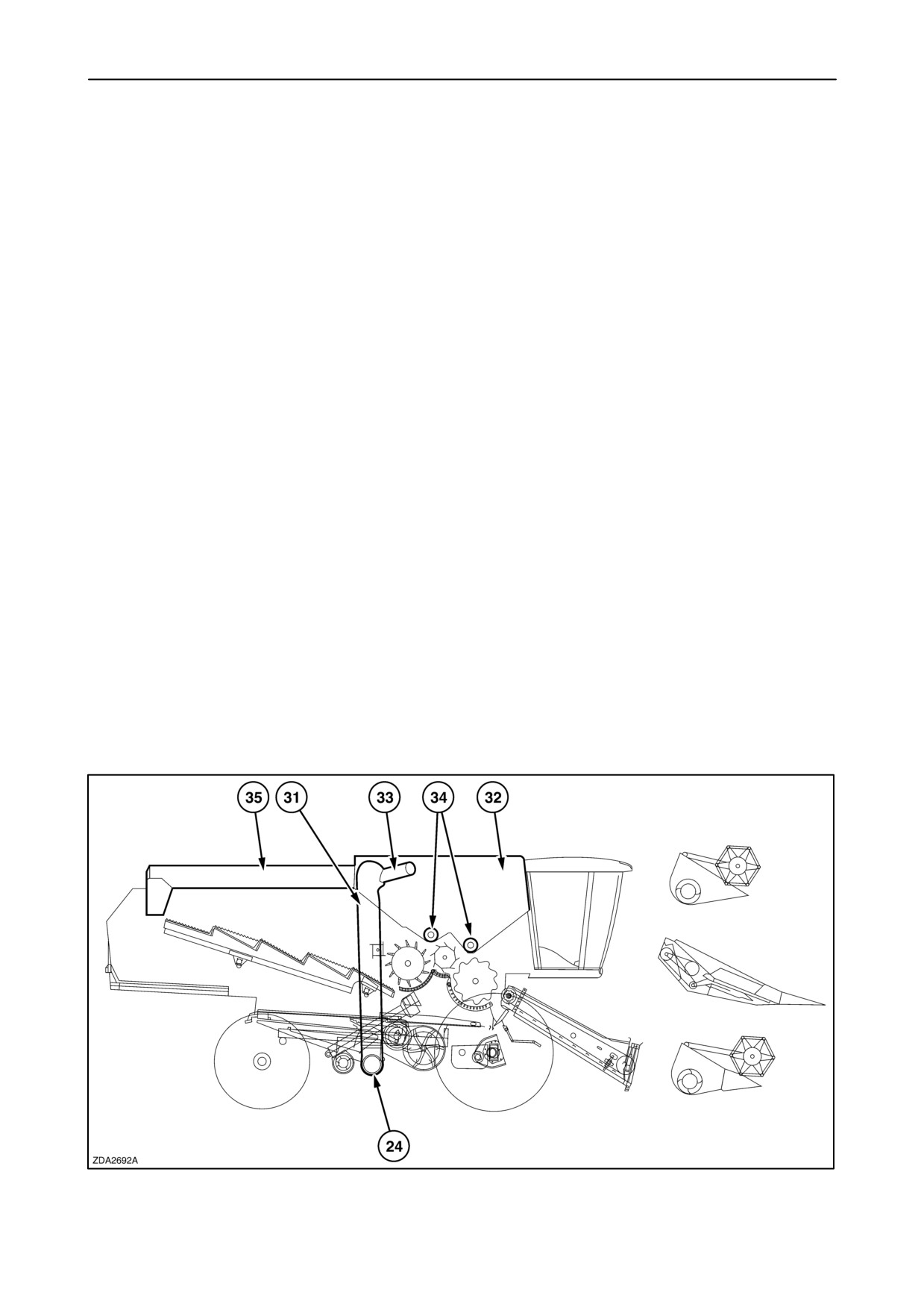
Hillside dividers are installed as standard equipment
In addition, the grain separated by the presieve 17 is
on the grain pan 8 where they ensure an even
guided by the small grain pan 28 to the lower sieve.
distribution of the material before it reaches the short
The installation of a presieve considerably increases
grain pan 28.
the cleaning shoe capacity as the main separation of
grain and chaff occurs at both finger grates. The lower
The cleaning shoe is composed of an upper shoe 26
sieve, or cleaning sieve, provides the final cleaning
and a lower shoe
27 which move in opposite
operation. Grain that passes through the cleaning
directions. A first separation takes place on the grain
sieve is carried over the grain plate 23 to the clean
pan as the lighter chaff forms the top layer and the
grain cross auger 24. Unthreshed heads which do not
heavier grain the bottom layer. The material falls
fall through the lower sieve are transported by the
through the finger grate 16, installed at the rear of the
returns auger(s) 25 to the roto-thresher(s) 29 for
grain pan, onto the presieve 17. The air coming from
rethreshing.
the secondary blow opening 18 of the cleaning fan 19
blows the chaff over the presieve so that grain with a
From the roto-thresher(s) this material is channelled
reasonably high degree of cleanliness falls through
by returns auger(s) 30 to the grain pan for cleaning.
the presieve. This action will be repeated a second
Divider plates divide the returned material evenly
time between the presieve 17 and upper sieve 20.
over the grain pan where the exclusive self-levelling
The air coming from the main blow opening 21 of
cleaning shoe or the fixed cleaning shoe takes over.
cleaning fan 19 blows the chaff over the upper sieve
out of the machine, while the grain, unthreshed heads
and small volumes of heavy chaff fall onto the lower
sieve 22.
5. Grain storage and unloading
The clean grain is channelled into the grain tank 32
by the clean grain cross auger 24, grain elevator 31
and bubble-up auger 33.
The grain tank is emptied by the grain tank unloading
augers 34 and the unloading tube auger 35.
8
3-9

SECTION 3 - FIELD AND SITE OPERATION
Crop settings
TYPE OF CROP
Optional equipment required
Drum speed
Concave
position
WHEAT
De-awning plates
560-850 rpm
10 mm - 3/8”
Rasp bar in front of concave
(varieties with white caps)
BARLEY
De-awning plates
640-900 rpm
10 mm - 3/8”
(some varieties)
WINTER
Idem barley
640-900 rpm
10 mm - 3/8”
BARLEY
Close de-awning plates, if necessary.
RYE
650-900 rpm
10 mm - 3/8”
TRITICALE
600-900 rpm
10 mm - 3/8”
OATS
640-800 rpm
10 mm - 3/8”
RICE
Spike tooth bars and concave
450-650 rpm
20 mm - 3/4”
Tracks
Smooth roto-thresher cover(s)
MAIZE
Maize header
320-400 rpm
25 mm - 1”
Maize concave
Smooth roto-thresher cover(s)
FLAX
640-800 rpm
10 mm - 3/8”
RAPE SEED
Vertical knives on the header
480-520 rpm
24 mm - 15/16”
Graepel sieve extension
Smooth roto-thresher cover(s)
3-10

SECTION 3 - FIELD AND SITE OPERATION
Rotary
Sieve openings
Straw chopper
separator
Fan speed
(If installed)
speed
Presieve
Lower
Upper
Speed
High
700-800 rpm
6 mm - 15/64”
5-7 mm
10 -12 mm
High
3/16” - 1/4”
3/8” -
1/2”
High
700 rpm
6 mm - 15/64”
5-7 mm
10 - 12 mm
High
3/16” - 1/4”
3/8” - 1/2”
High
700 rpm
6 mm - 15/64”
5-7 mm
10 - 12 mm
High
3/16” - 1/4”
3/8” - 1/2”
High
700 rpm
6 mm - 15/64”
5-7 mm
10 - 12 mm
High
3/16” - 1/4”
3/8” - 1/2”
High
700 rpm
6 mm - 15/64”
5-7 mm
10 - 12 mm
High
3/16” - 1/4”
3/8” - 1/2”
High
550-600 rpm
6 mm - 15/64”
5-7 mm
10 - 12 mm
High
3/16” - 1/4”
3/8” -
1/2”
High
650-700 rpm
6 or 9 mm
5-7 mm
10 - 12 mm
High
15/64” or 11/32”
3/16” - 1/4”
3/8” - 1/2”
Low
800-920 rpm
9 or 12 mm
12 mm - 1/2”
13 -15 mm
Low
11/32” or 1/2”
1/2” - 19/32”
High
500-550 rpm
3 or 6 mm
3-5 mm
4-7 mm
High
1/8” or 15/64”
1/8”-
3/16”
5/32” - 1/4”
Low
450-500 rpm
6 mm - 15/64”
3 mm - 1/8”
8 mm - 5/16”
High
(Grate:lower
Eccentric
position)
shaft low rpm
3-11

SECTION 3 - FIELD AND SITE OPERATION
TYPE OF CROP
Optional equipment required
Drum speed
Concave
position
SORGHUM
Special crop lifters on the header
640 rpm
10 mm - 3/8”
SAFFLOWER
320-440 rpm
27 mm - 1-1/16”
SOYA BEANS
Flex header
Smooth roto-thresher cover(s)
Maize concave
550 rpm
20 mm - 3/4”
Perforated auger covers
Perforated straw elevator bottom
SUNFLOWER
Sunflower header
320 rpm
27 mm - 1 -1/16”
to
Smooth roto-thresher concave
40 mm
Maize concave
(Dry conditions: cover plate concave)
MUSTARD
480-520 rpm
10 to 25 mm
3/8” to
1”
BUCKWHEAT
480 rpm
10 mm - 3/8”
GRASS SEED
- Fine
grass
Standard drum - moderate concave
920 rpm
5 mm - 3/16”
seed
- Coarse grass
560 rpm
17 mm - 2/3”
Universal drum - Spike tooth concave
seed
BEANS/PEAS
Perforated auger covers
Beans: 27 mm
1 -1/16”
Smooth roto-thresher cover(s)
320-360 rpm
Peas: 20 mm
Perforated straw elevator bottom
3/4”
CLOVER
Close de-awning plates, if necessary.
Maximum
3 to 5 mm
1/8” to 3/16”
3-12

SECTION 3 - FIELD AND SITE OPERATION
Rotary
Sieve openings
Straw chopper
separator
Fan speed
(If installed)
speed
Presieve
Lower
Upper
Speed
High
750-800 rpm
3 or 6 mm
6 mm - 15/64”
10 mm - 3/8”
High
1/8” or 15/64”
Low
550-700 rpm
6 or 9 mm
8 mm - 5/16”
12 mm - 1/2”
High
15/64” or 11/32”
Low
750 rpm
9 or 12 mm
7 mm - 1/4”
10-12 mm
High
11/32” or 1/2”
3/8”- 1/2”
Low
If losses
600-650 rpm
12 mm - 1/2”
7-8 mm
10-12 mm
Low
occur:
1/4” - 5/16”
3/8”- 1/2”
High
Grate in lower
position
High or Low
450-500 rpm
3 or 6 mm
0-6 mm
8-10 mm
High
1/8” or 15/64”
0 - 15/64”
5/16”- 3/8”
Eccentric
shaft low rpm
High or Low
550 rpm
6 mm - 15/64”
9 mm - 11/32”
12 mm - 1/2”
High
High
325 rpm
4 mm - 5/32”
1 mm - 3/76”
4 mm - 5/32”
High
High
400 rpm
6 mm - 15/64”
4 - 5 mm
5 mm - 3/16”
High
5/32” - 3/16”
High or Low
Maximum
9 mm - 11/32”
9 - 13 mm
Beans: 15 mm
High
11/32” - 1/2”
19/32”
Grate in lower
position
Peas: 10 mm
High
3/8”
High
Minimum
3 mm -1/8”
3 - 4 mm
8 mm - 5/16”
High
1/8” - 5/32”
3-13

SECTION 3 - FIELD AND SITE OPERATION
TO CHANGE FROM GRAIN TO MAIZE CONFIGURATION, THE FOLLOWING
MODIFICATIONS HAS TO BE DONE.
ACTION
SECTION
Header
- Install maize header
Refer to Operator’s manual of the maize header
- Install counterweights as required
Section 8 - SPECIFICATIONS
- Install additional lighting kit (flip-up headers)
Section 7 - ACCESSORIES
Straw elevator
- Install 4HB drive line
Section 7 - ACCESSORIES
- Adjust lower shaft
Section 3 - FIELD AND SITE OPERATION
- Remove intermediate cover plates
Section 3 - FIELD AND SITE OPERATION
- Install perforated bottom plate
Section 3 - FIELD AND SITE OPERATION
Threshing
- Install maize concave
Section 3 - FIELD AND SITE OPERATION
- Remove anti-dust plate
Section 3 - FIELD AND SITE OPERATION
- Remove anti-wrap shields
Section 3 - FIELD AND SITE OPERATION
- Install drum cover plates (If standard drum)
Section 7 - ACCESSORIES
Separation
- Low speed of the rotary separator
Section 3 - FIELD AND SITE OPERATION
- Set the multi-thresh system in the closed position
Section 3 - FIELD AND SITE OPERATION
Cleaning
- Install fan bottom shield
Section 7 - ACCESSORIES
- Install smooth roto-thresh cover(s)
Section 3 - FIELD AND SITE OPERATION
- Check if cleaning shoe is running at high rpm
Section 3 - FIELD AND SITE OPERATION
- Install pre sieve HC 1-5/8” (if necessary)
Section 3 - FIELD AND SITE OPERATION
- Install upper sieve HC 1-5/8” (in upper position)
Section 3 - FIELD AND SITE OPERATION
Straw chopper
- Remove or retract the counter knives
Section 3 - FIELD AND SITE OPERATION
- Remove shread bar
Section 3 - FIELD AND SITE OPERATION
- Reduce by halve of rotor knives
Section 3 - FIELD AND SITE OPERATION
- Low speed of the chopper rotor
Section 3 - FIELD AND SITE OPERATION
- Remove chaff blower
Section 3 - FIELD AND SITE OPERATION
(connect hydraulic lines to the valve)
- Set rear deflector plate in maize position
Section 3 - FIELD AND SITE OPERATION
Engine
- Install rotary dust screen brush
Section 7 - ACCESSORIES
3-14

SECTION 3 - FIELD AND SITE OPERATION
ACTION
SECTION
InfoViewt
Calibrations
Section
2
- CONTROLS, INSTRUMENTS AND
OPERATION
- Recalibrate “Header”
- Recalibrate “Concave position”
- Recalibrate “Upper sieve”
- Recalibrate “Lower sieve”
- Recalibrate “Maximum stubble height”
- Recalibrate “Flow sensor”
- Recalibrate “Moisture sensor”
Engine
Section 2 - CONTROLS, INSTRUMENTS AND
OPERATION
- adapt “Rotary screen brush”
Driveline
Section 2 - CONTROLS, INSTRUMENTS AND
OPERATION
- adapt “Tyre radius” (if tyres)
- adapt “Rear wheel assist” (if P.R.A.)
- adapt “Dual range” (if P.R.A.)
- adapt “Tracks type” (if tracks)
Header settings
Section 2 - CONTROLS, INSTRUMENTS AND
OPERATION
- adapt ”Header type”
- adapt ”Header platform type”
- adapt “Rows in use”
- adapt “Total rows”
- adapt “Row distance”
- adapt “Header raise rate”
- adapt “Header lower rate”
- adapt “Header lateral float”
- adapt “Header Autofloatt”
- adapt “Maximum stubble height”
- adapt “Hydraulic deck plates”
Threshing settings
Section 2 - CONTROLS, INSTRUMENTS AND
OPERATION
- adapt “Concave type”
Cleaning settings
Section 2 - CONTROLS, INSTRUMENTS AND
OPERATION
- adapt “Sieve loss sensitivity”
- adapt “Upper sieve type”
- adapt “Lower sieve type”
- adapt “Remote upper sieve”
- adapt “Remote lower sieve”
Residue settings
Section 2 - CONTROLS, INSTRUMENTS AND
OPERATION
- adapt “Chaff blower”
Precision farming settings
Section 2 - CONTROLS, INSTRUMENTS AND
OPERATION
- adapt “Crop”
3-15
SECTION 3 - FIELD AND SITE OPERATION
Kill stall
The only way to accurately check the performance of
NOTE: Make only one adjustment at a time so that
the combine is to complete a ”kill-stall”.
any change in combine performance can be
attributed to that particular adjustment.
1.
Operate the combine in a section of the field that
best represents the overall crop. Be sure the
NOTE: Lower the concave (completely down) before
combine is at least 100 m (328 ft) into the crop
reengagement of the threshing.
and travelling at the normal operating ground
speed.
Performance indicators
2.
Press the plus ”+” and minus ”-” keys (keypad)
There are four indicators, which will tell you how well
together for 2,5 seconds. Apply the brakes gently
the combine is performing. These four indicators are:
and allow the complete combine to stop. This will
leave crop material as it was during actual
harvesting.
• Grain tank sample
3.
Disengage the threshing and header
• Distribution of material on the grain pan and
engagement system clutch, move the multi
upper sieve
function handle to neutral, and restart the engine
immediately. This prevents the engine from
• Type and amount of returns
overheating and from being damaged. Run the
engine on low idle for five minutes before
• Losses
stopping the engine. Then stop the engine.
4.
Check the grain tank sample for complete
By correctly reading these indicators and being
threshing, cleanliness and damage.
familiar with the combine, you can make the
necessary adjustments to correct any problem and
5.
Walk out in the front of the header and check the
improve the overall combine performance.
crop loss before the header has contacted the
crop (preharvest loss).
Grain tank sample
6.
Check the crop loss in an area where only the
A large amount of trash in the grain tank indicates the
header has travelled (header loss).
crop is being overthreshed and/or the cleaning fan
speed is too slow. The first step to correct this
7.
Check the distribution of material on the grain
problem is to increase the concave clearance and/ or
pan.
reduce the drum speed. This reduces or eliminates
the material break-up caused by overthreshing. Then
8.
Check the type, amount and distribution of
increase the cleaning fan speed if the trash is heavier
material on the sieves.
than the grain or close the upper sieve if the trash is
larger than the grain.
9.
Check the type and amount of returns.
Cracked or damaged grain can be caused by a
10. Check the total loss in a 60 cm (23-5/8“) wide area
concave setting that is too close to the drum. Increase
across the width of the cleaning shoe. Subtract
the concave clearance and then reduce the drum
preharvest and header losses to determine the
speed to correct the problem.
machine loss. Use a drop screen to check the
machine loss directly.
Bunch feeding can cause grain damage in the straw
11. With all previous factors considered, readjust the
elevator. An incorrect straw elevator chain tension
combine.
can also cause grain damage.
3-16
SECTION 3 - FIELD AND SITE OPERATION
Excessive returns will contribute to grain damage due
Returns sample
the additional pass(es) the grain must take through
the drum/concave area. Plugged concave can cause
It is normal for the return sample to contain a few
grain damage because the free grain cannot get out
unthreshed heads. The purpose of the returns
of the concave area.
system is to return unthreshed heads to the threshing
area for another pass. However, a large quantity of
unthreshed heads indicates the concave clearance is
too great.
Loose elevator chains can also cause grain damage.
It is important to maintain the proper tension on these
chains.
If the return sample contains a large quantity of clean
grain, the cleaning fan speed should be reduced and/
or the lower sieve should be opened more.
Unthreshed material in the grain tank can be caused
by underthreshing or the lower sieve that is opened
Losses
too wide. Increase the drum speed and reduce the
concave clearance as needed to correct the problem.
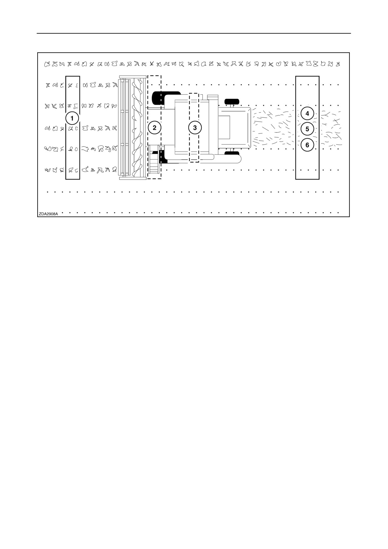
Losses may occur at different stages: (see fig. 9)
Reduce also the lower sieve opening slightly to obtain
a cleaner grain tank sample.
1.
Pre-combining losses: (i.e. losses found in
front of the combine) are usually caused by
adverse weather conditions, poor crop conditions
Grain pan/ upper sieve distribution
and crop maturity.
2.
Header losses: (i.e. losses found behind the
header and outside of the tyres) may be caused
The distribution of material on the grain pan affects
by improper header adjustments.
the distribution of material on the sieve. The
distribution on the grain pan should be level to slightly
higher directly under the drum and taper slightly
3.
Leakage losses: may be caused by damaged
towards both sides.
seals or holes in bottom auger covers.
4.
Shoe losses: may be caused by a poor sieve
adjustment, a low cleaning fan speed, or when
The front third of the upper sieve should be
working on slopes (exceeding the capacity of the
completely clean. The middle third should have some
self levelling system (if fitted).
grain but mostly residue. The rear third of the upper
sieve should have only residue.
5.
Fan losses: are caused by an excessive
cleaning fan speed.
If there is some grain on the rear third of the upper
6.
Straw walker losses: These can be unthreshed
sieve, returns will be increased and there is a
ears (underthreshing) or grains, due to poor
possibility that grain will ride out the back of the
adjustment of drum and concave or excessive
combine. Open the upper sieve to allow more of the
ground speed.
grain to fall onto the lower sieve.
Total losses (Lt) caused by the machine:
If the material on the upper sieve is broken into small
pieces, the crop is being overthreshed. This can plug
Lt = (2 + 3) + (4 + 5)+6 - 1
the upper sieve and cause high losses. Increase the
concave clearance and/ or reduce drum speed to
decrease the threshing action.
Functional losses (Lf)
Lf = 4 + 5 + 6
Unthreshed heads indicate the drum speed should be
increased and/ or the concave clearance should be
reduced. Unthreshed heads can also be caused by
worn rasp bars and worn concaves.
3-17
SECTION 3 - FIELD AND SITE OPERATION
9
The area of loss is determined by the location of the
Grain on the ground directly behind the combine and
grain in relation to the combine. Each of these areas
the width of the shoe is caused by incorrect combine
must be checked to accurately determine which
adjustment(s), too high a ground speed, or leakage.
combine adjustments (if any) can be made to reduce
the loss.
Shoe losses (4) can be caused by a build-up of
Grain on the ground in front of the combine head (1)
material on the top sieve which allows the grain to ride
is defined as preharvest loss and is usually caused by
out the back of the combine. This can be due to the
the weather. Determine the amount of this loss before
sieve opening being closed or opened too much, the
taking the combine into the field.
rear of the sieve raised too high (sieve angle too
extreme), or by a too low cleaning fan speed.
Grain found behind the head, but to the outside of the
drive tyres (2) is considered loss from the head.
These losses can be caused by improper head
Losses (5) can also be caused by a cleaning fan
adjustments or improper combine ground speed.
speed that is too high. The grain is then blown out of
the back of the combine.
Grain on the ground directly beneath the combine (3)
is leakage. Holes in the auger bottoms and damaged
seals can result in large losses which are often
An uneven loading of material on the top sieve can
mistaken for shoe and straw walker losses (6).
also cause losses.
3-18
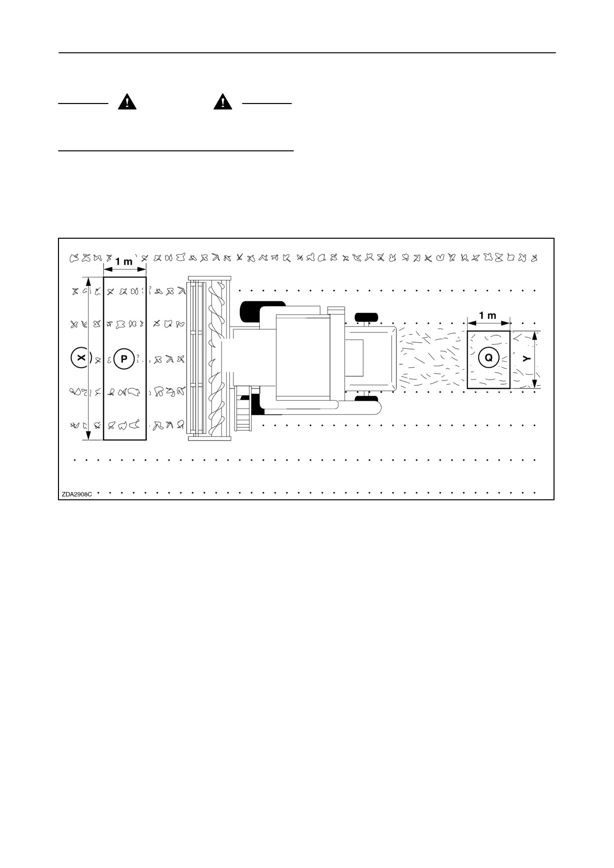
SECTION 3 - FIELD AND SITE OPERATION
How to obtain an idea on loss level
CAUTION
The straw chopper must be disconnected when
checking loss.
Example:
A 6-straw walker combine with a 17 ft (5.10 m)
grain header operating in wheat.
Average yield: 5000 kg/ha.
10
• Surface P= surface being harvested:
1 meter multiplied by X (header width) = 5.10 m2.
• Surface Q = surface of the material being cut in
surface P, behind the machine (i.e. swath):
1 meter multiplied by Y.
(drum width, i.e. 1.5 meter) = 1.5 m2.
• Consider a loss level of 1% = 50 kg/ha or
5 grams/m2 crop.
Surface Q will then contain the functional losses
(i.e. cleaning shoe, straw walker, fan) of surface
P (5.1 m2), being 5 x 5.1 = 25.5 grams.
• Considering the average weight of wheat being
23000 grains/kg, this means:
586 grains in
surface Q. (1% loss level!)
• An average human hand with spread fingers
covers a surface of approximately 0.03 m2. This
means that, if the grain loss is evenly spread, 18
grains can be found underneath the hand,
representing 1% grain loss for a 5000 kg/ha yield.
3-19
SECTION 3 - FIELD AND SITE OPERATION
HEADER
Attaching the header to the combine
To attach the header to the combine, proceed as
follows:
1. Make sure that the top of the straw elevator
where the header is attached is clean.
2. Position the combine to align the straw elevator
with the header aperture.
3. Move the combine in first gear to position the
straw elevator. Hook on the header, and raise the
straw elevator and header.
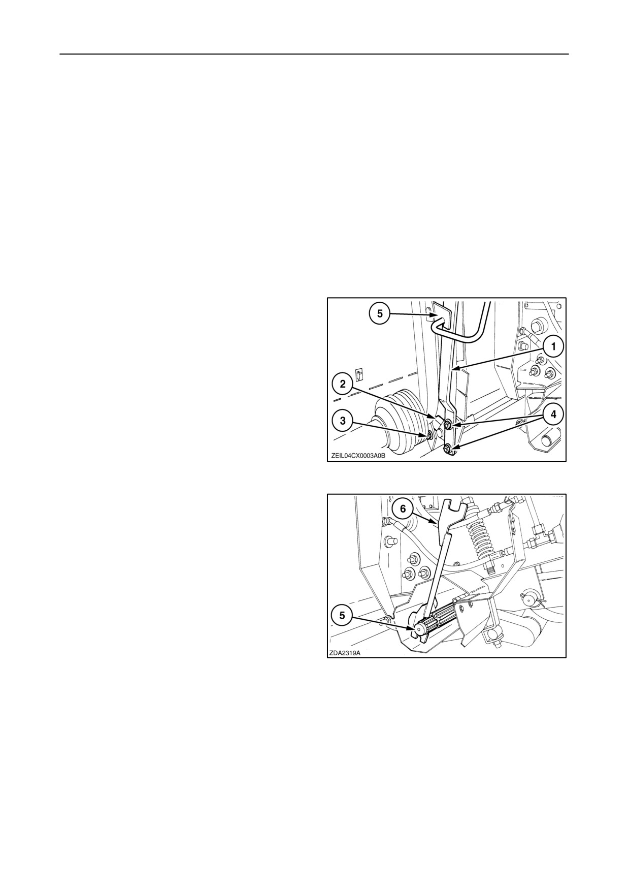
4. Attach quick-attach lever 1 so that the hooks 2
are in full contact with pins 3. If not, adjust lever
1 with bolts 4 so that some resistance is felt when
engaged latch 5 over lever 1.
11
5. Connect header drive coupling 5. Use the special
tool 6 fitted to the left-hand side of the straw
elevator to bring the splines of the header drive
shaft in line with the splines of the header p.t.o.
shaft.
12
3-20
SECTION 3 - FIELD AND SITE OPERATION
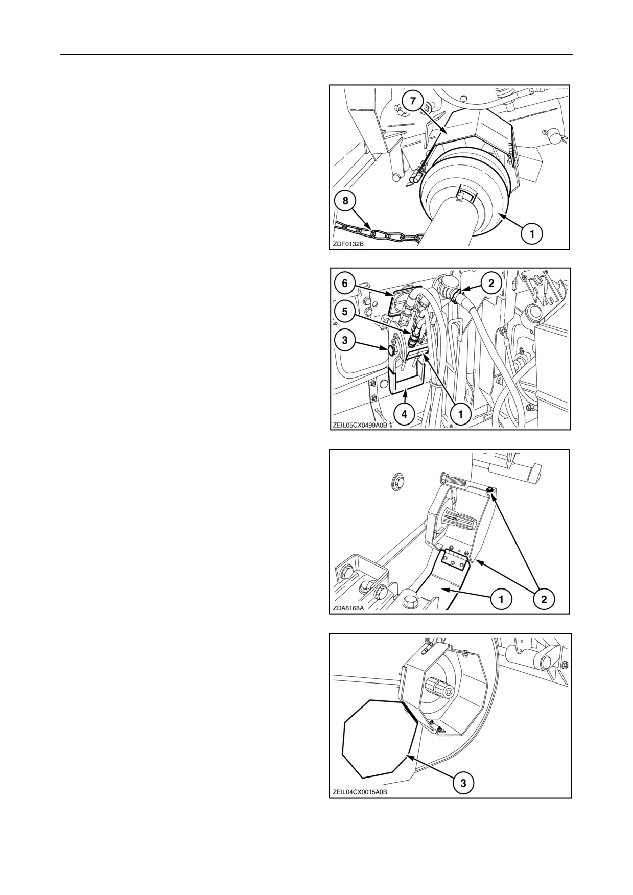
6. Close cover 7 to protect header drive coupling 1.
7. Attach chain 8 to the p.t.o. support on the header.
13
8. Connect electrical plug 2.
9. To connect the quick-release coupler, open cover
6, bring hydraulic block 5 to 1 and turn down
handle 4 until lock
3 jumps into its security
groove.
14
10. In case of a maize header with a stalk chopper,
open cover 1 at the right-hand side of the straw
elevator, loosen two bolts 2 and remove the
guard.
11. Connect the chopper drive coupling. Use the
special tool fitted to the left-hand side of the straw
elevator to bring the splines of the header drive
shaft in line with the splines of the header p.t.o.
shaft.
12. Close cover 1 to protect chopper drive coupling.
15
NOTE: Install the guard 3 as shown.
16
3-21
SECTION 3 - FIELD AND SITE OPERATION
Detaching the header from the combine
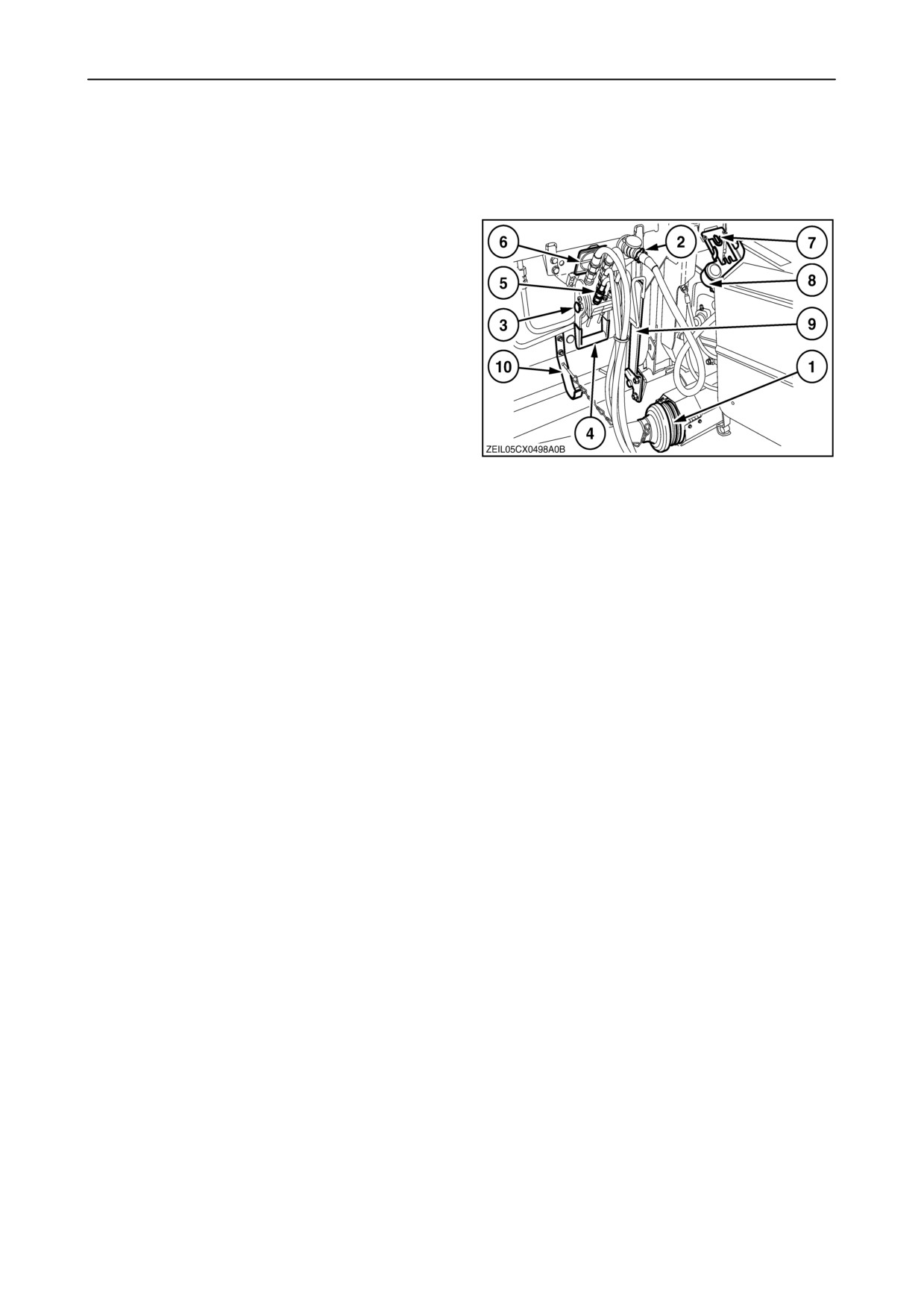
To detach the grain header proceed as follows:
1. Set the reel in its lowest and rearmost position.
2. Disconnect the following parts:
• Header drive coupling 1.
• Electrical connection
2 and attach it to
support 8.
• Quick-release coupler: Pull lock 3 and turning
over handle 4. Take out hydraulic block 5.
Close cover 6, and hook hydraulic block 5
onto support 7.
3. Release the quick-attach lever 9.
4. Position the header on level ground or on a trailer.
17
5. With the engine running at idle speed, lower the
straw elevator to release it from the header, then
move the combine rearwards.
NOTE: Refer to the separate Operator’s manual for
the header type attached to your combine.
3-22
SECTION 3 - FIELD AND SITE OPERATION
HEADER HEIGHT CONTROLS
When changing the header (grain header), perform
the header settings and header calibrations (refer
to “SECTION 2 - CONTROLS, INSTRUMENTS AND
OPERATION”, Paragraph: ”VI CALIBRATIONS AND
CONFIGURATIONS”.
To enter an automatic header height control mode
(stubble height and/or Autofloatt, compensation),
proceed as follows after doing first the calibrations:
Stubble height and Autofloatt mode
In this mode, without Autofloatt potentiometer
sensors, the header operates at a preselected
stubble height.
If the Autofloatt potentiometer sensors are installed,
the header will follow the field contours at a
preselected stubble height.
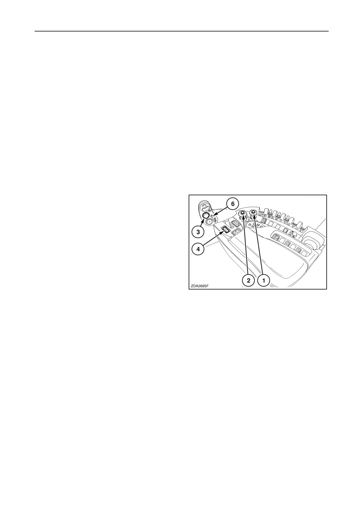
1. Engage the threshing mechanism and the straw
elevator with switches 1 and 2.
2. Set header memory tumbler switch 4 in stubble
height/Autofloatt mode position 1 or 2.
3. Lower the header to the desired cutting height
using header height and header lateral flotation
rocker switch 3.
4. Press automatic header height control button 6
for minimum 2 seconds to store.
(A beep will confirm)
18
NOTE: It is possible to store two different header
heights values by using header memory tumbler
switch 4 in stubble height/Autofloatt mode position
1 or 2.
5. To change one of the memorised header height
setpoints during working, using the header height
and header lateral flotation rocker switch 3 (slow
up/down) to raise or lower the header to the
desired value. Press the automatic header height
control button 6 for minimum 2 seconds to store
the new height position. (A beep will confirm)
6. At the headlands the operator can press
automatic header height control button 6 twice to
lift the header out of the crop.
To reenter the automatic mode give a pulse on the
automatic header height control button 6 and the
header will be relower to the preselected height
position.
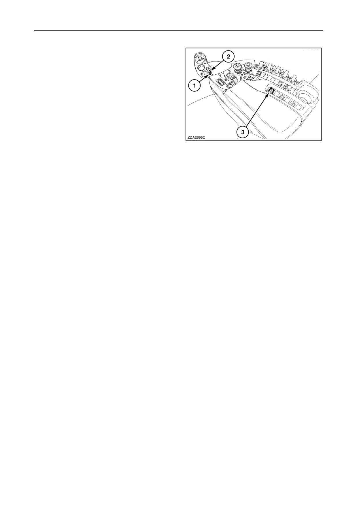
3-23
SECTION 3 - FIELD AND SITE OPERATION
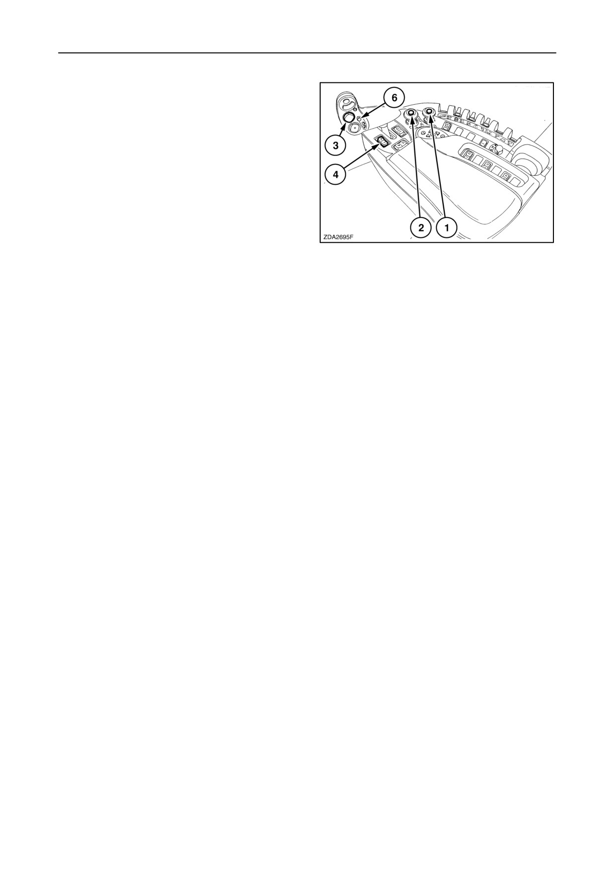
NOTE: To change only the working setpoint, press
slow up/down with header height and header lateral
flotation rocker switch
3 without confirming by
automatic header height control button 6. The system
will stay in automatic mode.
NOTE: Operating the header height control rocker
switch 3 (only fast speed up or down, no lateral tilt)
disengages the automatic mode system completely
into the transport mode (priority).
19
NOTE: It is also possible to switch over from one
header height to an other or even to header
compensation by using memory tumbler switch 4.
IMPORTANT: It is only possible to change the header
height position as long as they are working in the
range of the “Maximum stubble height”. To change
the maximum stubble height, refer to “SECTION 2 -
CONTROLS, INSTRUMENTS AND OPERATION”,
paragraph
“VI:
CALIBRATIONS
AND
CONFIGURATIONS”, headed “11.Header”.
An automatic compensation is build in when
touching the ground. After the header clears the
ground, it automatically returns to the preset
stubble height. This automatic compensation can
be adjusted with the threshold pressure. A lower
threshold pressure will limit forces on the ground
when touching the ground.
Refer to
“SECTION
2
-
CONTROLS,
INSTRUMENTS AND OPERATION”, paragraph
“VI: CALIBRATIONS AND CONFIGURATIONS”,
headed “11.Header”.
3-24
SECTION 3 - FIELD AND SITE OPERATION
Compensation mode
Use this mode when harvesting peas and/or laid
crops. In this operation mode, the header slides over
the ground with a preselected pressure.
In this mode it is also possible to obtain an automatic
lateral flotation if Autofloatt potentiometer sensors
are installed. The sensors should be connected to the
combine and the outer header skids should be in
pivoting position (i.e. hanging loose).
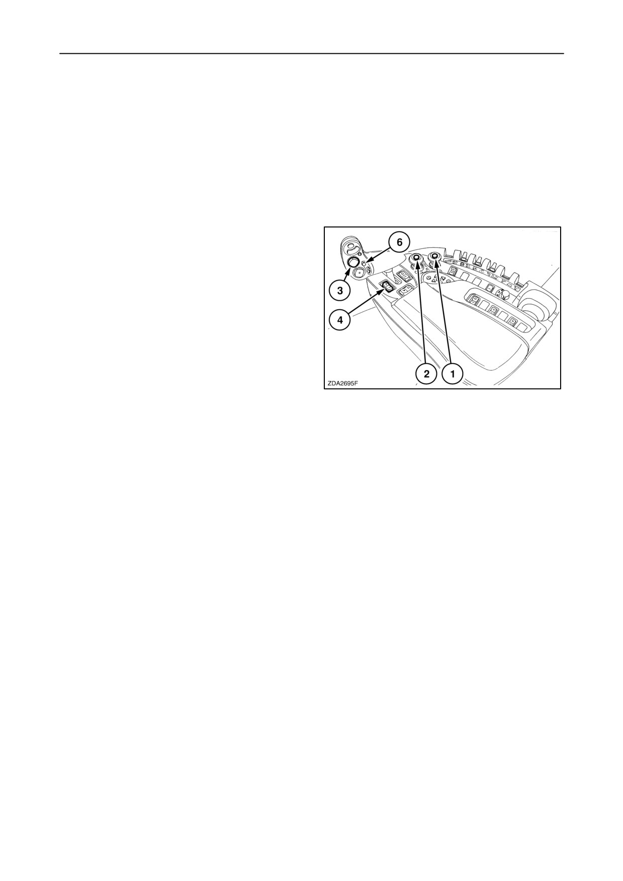
1. Engage the threshing mechanism and the straw
elevator with switches 1 and 2.
2. Set header memory tumbler switch
4 in
compensation mode.
3. Lower the header to the desired cutting height
using header height and header lateral flotation
rocker switch 3.
4. Press automatic header height control button 6
for minimum 2 seconds to store.
(A beep will confirm)
20
NOTE: The calibrated header pressure means the
pressure in the header lift cylinders with the header
+/- 15 cm (6 inches) above the ground.
5. To change the preselect pressure during working,
using the header height and header lateral
flotation rocker switch 3 (slow up/down) to the
desired pressure. Press the automatic header
height control button 6 for minimum 2 seconds to
store the new pressure. (A beep will confirm)
6. At the headlands the operator can press
automatic header height control button 6 twice to
lift the header out of the crop.
To reenter the automatic mode give a pulse on the
automatic header height control button 6 and the
header will lower until the preselected pressure is
obtained.
NOTE: To change the pressure, press slow up/down
with header height and header lateral flotation rocker
switch 3 without confirming by automatic header
height control button
6. The system will stay in
automatic mode.
NOTE: It is also possible to switch over from one
header height to an other or even to header
compensation.
3-25

SECTION 3 - FIELD AND SITE OPERATION
NOTE: The status bar on the InfoViewt monitor
shows in which mode the header works: There are
three different modes.
1. Stubble height mode
2. Autofloatt mode
3. Compensation mode
NOTE: The status bar on the InfoViewt
shows if
touching the ground during working in stubble or
Autofloatt mode,
NOTE: If the automatic mode is left, a message
“AUTO HHC DISABLED” will appear on a pop-up
screen of the InfoViewt monitor.
3-26
SECTION 3 - FIELD AND SITE OPERATION
Transport mode
This mode is automatically selected when:
• Straw elevator is not engaged.
• Road mode is selected.
• Push on the header height rocker switch.
Flex header operation
To work with a flex header perform the header type
configuration. Refer to “SECTION 2 - CONTROLS,
INSTRUMENTS AND OPERATION”, paragraph:
“VI CONFIGURATIONS AND CALIBRATIONS”,
headed: “11.Header”.
AUTO HEADER LIFT
This automatic system is build in to protect the header
skid shoes by reversing the combine.
• Flex header: The header lift up two seconds after
the header skid shoes no more touching the
ground.
• Other headers: The header lift up one second
after the header skid shoes no more touching the
ground.
To get this system, the following conditions has to be
done.
• Auto header lift installed, refer to
“SECTION 2 - CONTROLS, INSTRUMENTS
AND OPERATION”, paragraph:
“VI CONFIGURATIONS AND CALIBRATIONS”,
headed: “11.header”.
• Autofloatt installed, refer to
“SECTION 2 - CONTROLS, INSTRUMENTS
AND OPERATION”,
“VI CONFIGURATIONS AND CALIBRATIONS”,
headed: “11.header”.
• Field mode selected
• Thresher engaged
• Straw elevator engaged
• Working in automatic mode
• Reverse driving
3-27
SECTION 3 - FIELD AND SITE OPERATION
REEL TO GROUND SPEED SYNCHRONIZATION
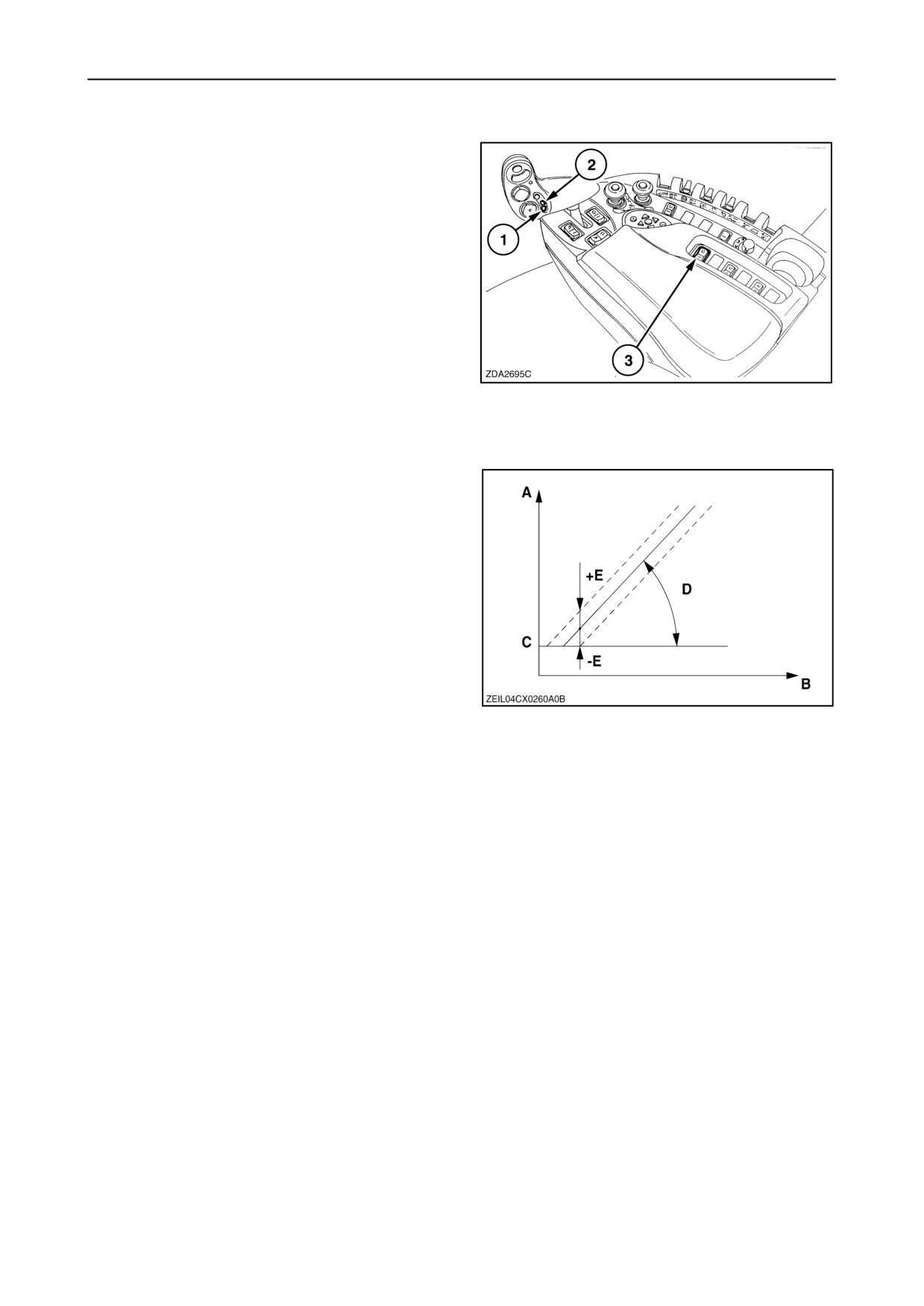
The reel to ground speed synchronization system is
an automatic system which, if switched on with the
reel speed synchronization engagement switch 3,
creates a linear relation ship of the reel speed with the
ground speed.
The basic ratio between the reel and the ground
speed can be increased or decreased with the reel
speed control switches 1 and 2.
21
• A= Reel speed (km/h)
• B= Ground speed (km/h)
• C= Minimum reel speed
(setting with InfoViewt monitor)
• D= Auto reel speed slope
(depends the header type)
• E= Auto reel speed offset
22
IMPORTANT: Before setting the reel speed, check (if
mechanical reel drive) if the reel speed sensor is
“installed“ in the configuration info screen and adjust
the “Minimum reel speed (C)”. Select these items on
the InfoViewt monitor to adjust. Refer to “SECTION
2
- CONTROLS, INSTRUMENTS AND
OPERATION”, paragraph: “VI CONFIGURATIONS
AND CALIBRATIONS”, headed: “11.Header”.
For example:
If the Auto reel speed offset (E) = 0 km/h and the
ground speed (B) = 4 km/h (2.5 mile/h): This means
that the tip speed of the reel= 4 km/h. (2.5 mile/h)
NOTE: How higher the auto reel speed offset
setpoint, how higher the tip speed of the reel in
relation with the ground speed.
3-28
SECTION 3 - FIELD AND SITE OPERATION
To obtain a proper reel synchro control, proceed as
follows:
1. Set the reel speed synchronization engagement
tumbler switch 3 in the ON position.
2. Operate the combine in a section of the field that
best represents the overall crop with a minimum
ground speed of 1 km/h (.6 mph).
3. Adjust the reel speed with the reel speed
switches 1 and 2 to match with the combine
ground speed.
23
If you now change the combine ground speed, the
reel speed will change automatically according to the
ground speed change.
NOTE: On headlands or whenever, lifting the header
out of the operational zone
(disengaging of
hectare/acre counter), the reel speed will be
maintained until the header is lowered again.
3-29
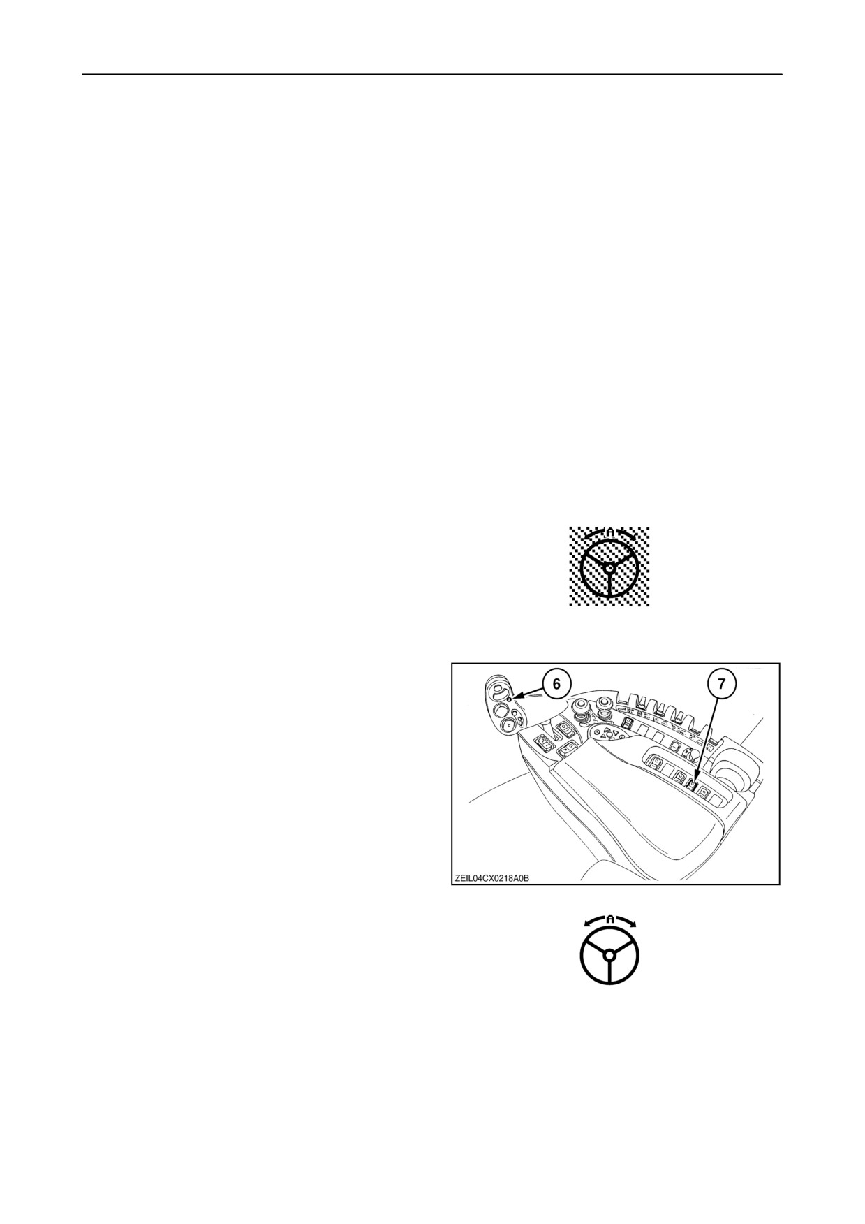
SECTION 3 - FIELD AND SITE OPERATION
SMARTSTEERt SYSTEM (IF INSTALLED)
The SmartSteert system guides the combine
automatically along a crop edge, either left-hand or
right-hand side.
To perform the calibrations refer to “SECTION 2 -
CONTROLS, INSTRUMENTS AND OPERATION”,
Paragraph:
“CALIBRATIONS
FOR
SMARTSTEERt SYSTEM”.
Enabled mode:
• The SmartSteert system is switched on to its
enabled (stand by) mode by turning slightly the
steering wheel, so the sensor recognised and
pressing the SmartSteert, rocker switch (7) for
at least two seconds.
NOTE: The SmartSteert system can only be
switched on from its deactivated state to its enabled
(stand by) mode as described above.
A signal will sound and a greyed SmartSteert
icon will show in the indicator bar (left upper
corner) on the InfoViewt monitor.
Activated (Operation) mode:
• The combine must move forward with a minimum
speed of 0.5 km/h. ( 0.32 miles/h)
• The operator has not been turning the steering
wheel for at least two seconds.
• Press automatic header height control button (6),
the SmartSteert system goes into HHC mode
and becomes active and will steer the combine
along the selected edge of the crop.
24
If the SmartSteert symbol in the indicator bar
on the InfoViewt is appearing with a white
background means that the SmartSteert
system is activated (operational).
3-30
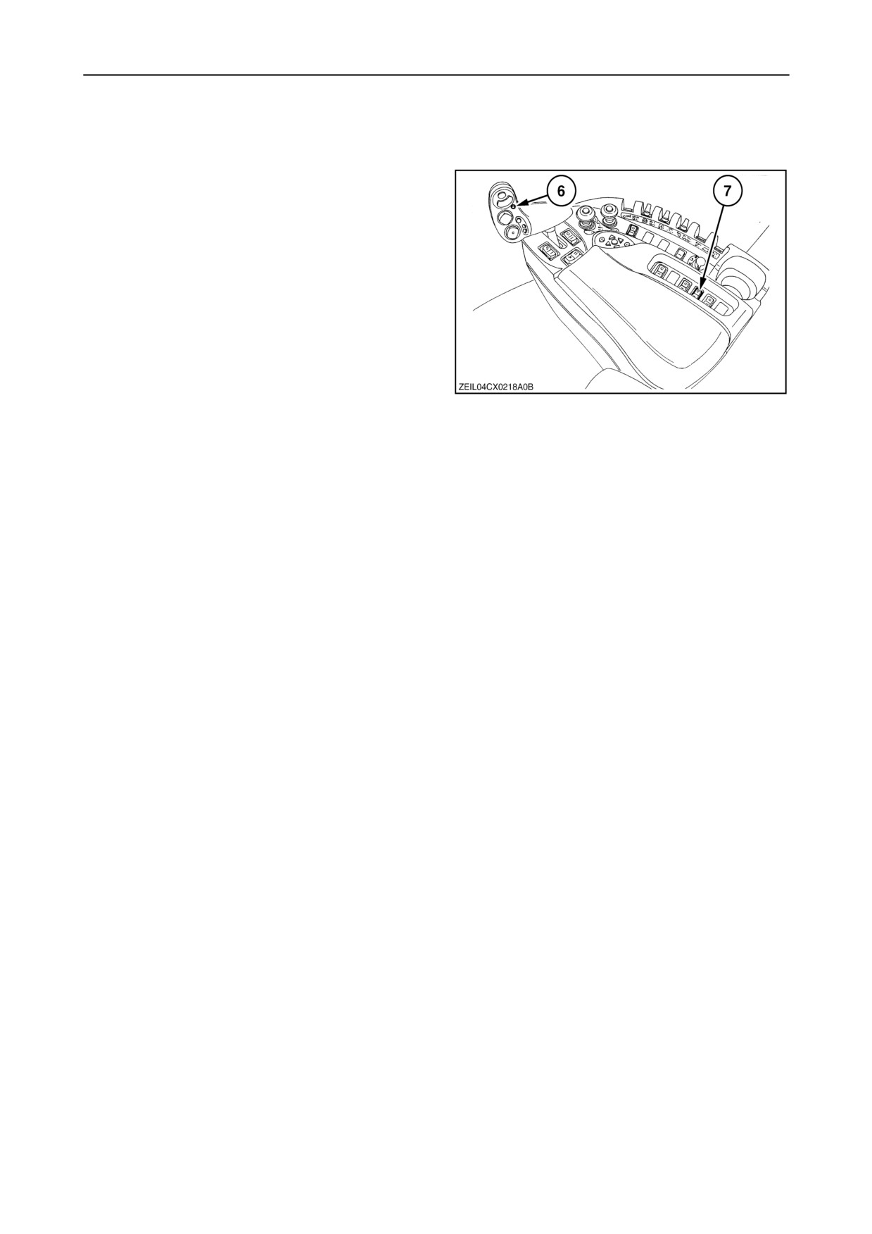
SECTION 3 - FIELD AND SITE OPERATION
The SmartSteert system is automatically switched
off from its activated mode when:
• the automatic header height control button (6) is
pressed two times.
• the ground speed is lower than 0.5 km/h
(0.32 Miles/h) or the combine is reverse driving.
• the operator is turning the steering wheel.
• the signal quality from the HGS sensor is too low
or no crop edge is detected or end of crop is
detected.
NOTE: In the enabled mode, the SmartSteert
system is not controlling the steering wheels
anymore so the combine will continue to drive in the
last controlled driving direction as long as the driver
25
does not turn the steering wheel in the cab.
The SmartSteert system is turned off completely
when:
• switching off and on the ignition key.
• pushing on the emergency stop button.
• pushing the SmartSteert rocker switch (7) once
when the SmartSteert system is in its activated
or its enabled (stand by) mode.
3-31
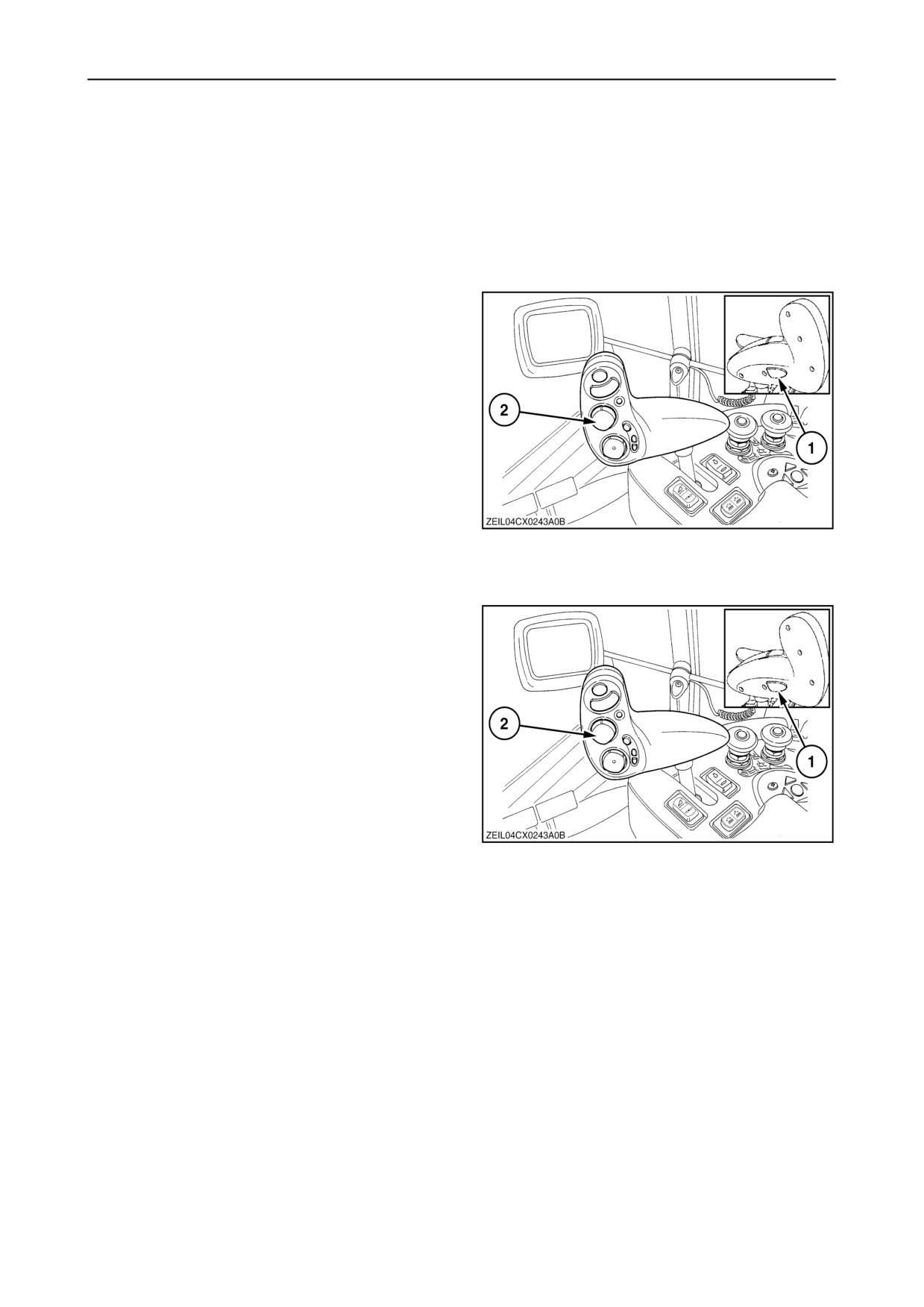
SECTION 3 - FIELD AND SITE OPERATION
Switching edges:
NOTE: Except for crop edge calibration, the HGS will
not automatically switch or detect a left or right crop
edge.
NOTE: Switching of the crop edge can only be done
manually and only when the SmartSteert system
is in it’s enabled position.
1. To switch, press and hold the neutral unlock
switch (1) and at the same time press and hold
the header lateral float rocker switch
(2) for
minimum two seconds.
Left for left-hand side crop edge and right for
right-hand side crop edge.
2. A sound signal indicates that the switching has
been done.
3. The HGS sensor turns now to the left-hand or the
right-hand side to focus on the selected crop
edge.
26
Offset adjustment
It is also possible to fine-tune the distance between
the crop edge and the header side. The adjustment
can only be done when the SmartSteert system is
in it’s operating mode.
1. To switch, press and hold the neutral unlock
switch (1) and at the same time press the header
lateral flotation rocker switch (2) shortly.
Left for left-hand side fine adjustment and right for
right-hand side fine adjustment.
27
2. Each pulse will adjust the offset with 10 cm (4”) to
the left or to the right and the newly selected offset
will be saved automatically.
NOTE: The offsets are reset automatically each time
the crop edge calibration is done.
3-32
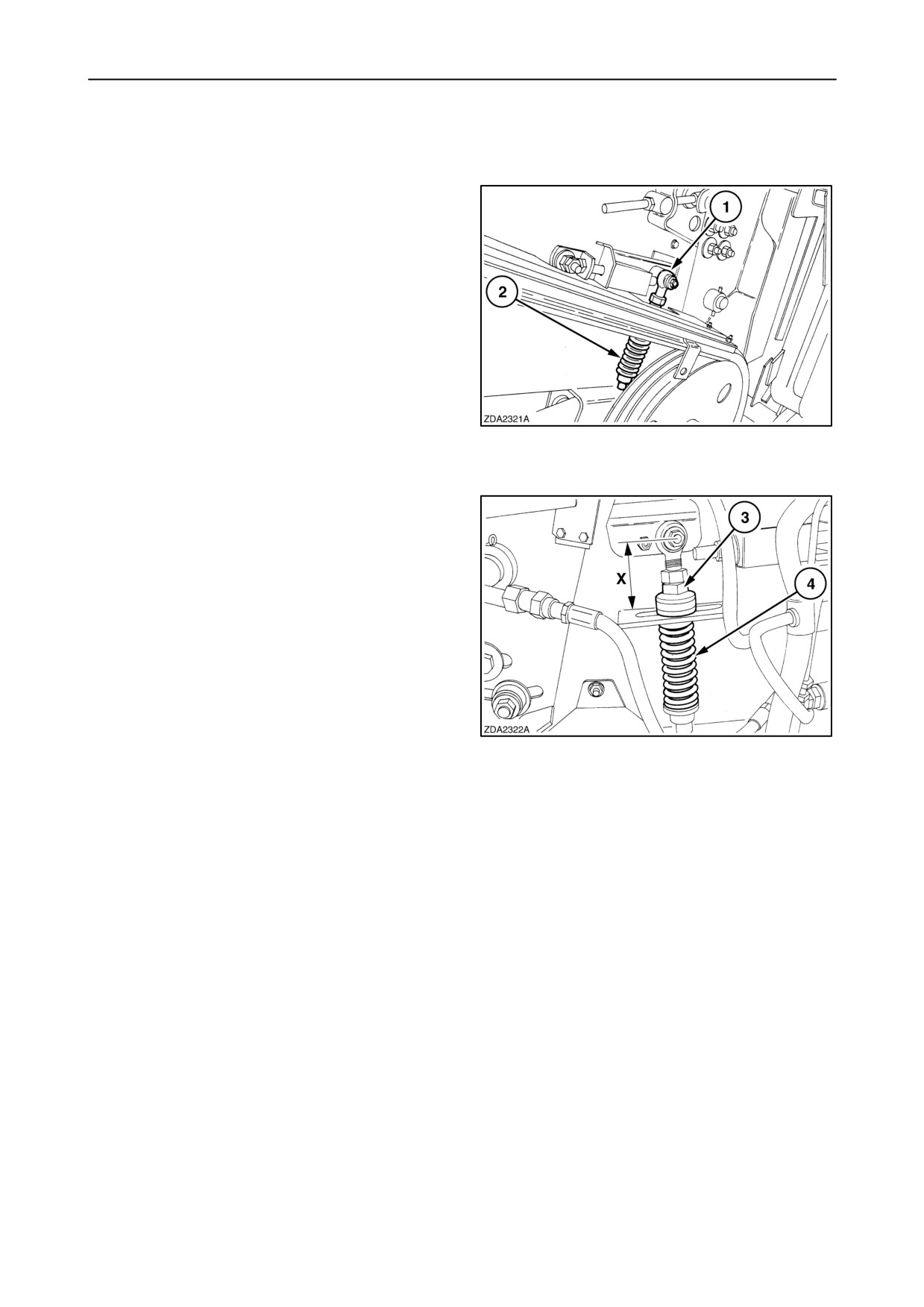
SECTION 3 - FIELD AND SITE OPERATION
FEEDING/STRAW ELEVATOR
Lower shaft adjustment
The straw elevator bottom shaft 1 is spring-tensioned
so that it can float according to the amount of material
being handled.
The spring tension 2 must be adjusted according to
the crop being harvested.
28
• Models with front face adjustment.
For all crops other than maize:
1. Adjust special nut 3 on both sides until distance
“X” measures 90 - 93 mm (3 1/2’’ - 3 21/32’’).
2. If necessary, adjust spring 4 to a length of
111 - 113 mm (4 3/8’’ - 4 1/2’’).
For maize crops:
1. Adjust special nut 3 on both sides until distance
“X” measures 112 - 114 mm (4 13/32’’ - 4 1/2’’).
29
2. If necessary, adjust spring 4 to a length of
88 - 90 mm (3 15/32’’ - 3 1/2’’).
NOTE: For sunflowers with big heads is it
recommended to adjust the lower shaft in maize
position.
3-33
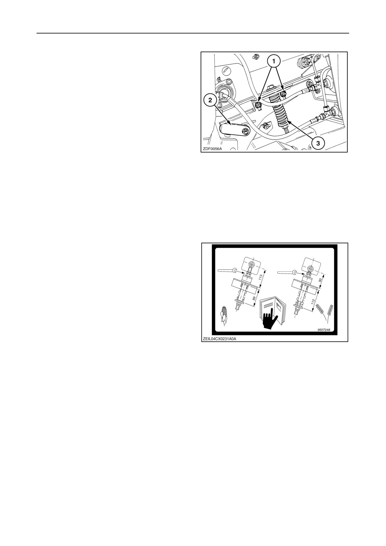
SECTION 3 - FIELD AND SITE OPERATION
• Models without front face adjustment (with or
without lateral flotation).
For all crops other than maize:
1. Loosen nuts 1 on both sides.
2. Adjust support 2 in the lower position as shown.
3. Tighten nuts 1 on both sides.
4. Adjust spring 3 to a length of
111 - 113 mm (4 3/8’’ - 4 1/2’’).
For maize crops:
1. Loosen nuts 1 on both sides.
30
2. Adjust support 2 in the upper position.
3. Tighten nuts 1 on both sides.
4. Adjust spring 3 to a length of
88 - 90 mm (3 15/32’’ - 3 1/2’’).
NOTE: For sunflowers with big heads is it
recommended to adjust the lower shaft in maize
position.
NOTE: You can also find the lower shaft adjustments
on a decal at the right-hand side of the straw elevator.
31
3-34
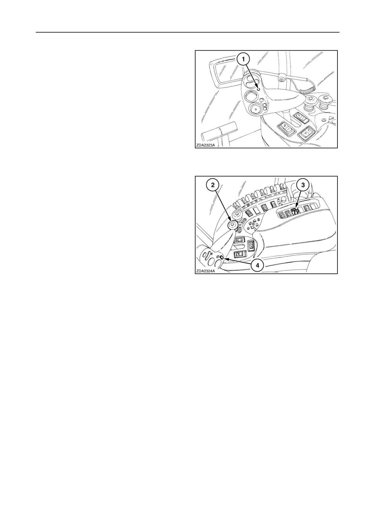
SECTION 3 - FIELD AND SITE OPERATION
Header and straw elevator reversing system
The combine is equipped with a system to reverse the
header reel (or the gathering chains, in case of a
maize header), the auger and the straw elevator
should a blockage occur.
If, during operation, a feed auger and/or a straw
elevator blockage occurs which makes the slip
clutch(es) slip, proceed as follows:
1. Stop the forward travel of the combine
immediately and disengage the header drive with
quick stop button 1.
32
2. Reverse the combine a few metres.
3. Let the engine run at maximum speed and switch
OFF the header engagement switch 2.
4. Engage reverser switch
3.
(if field mode is
selected).
5. Press the reel speed decrease button 4 (lower
part) to reverse the rotation of the header and
straw elevator
NOTE: Push the reel speed increase button to rotate
the header and straw elevator forwards.
33
6. When the blockage has been expelled,
disengage reverser switch
3 and wait two
seconds before engage the header engagement
switch 2.
IMPORTANT: It is not possible to remove all
blockages using the reversing system. If necessary,
remove the blockage manually. Refer to the next
paragraph
”header and/or straw elevator
blockage-manual clearing”.
NOTE: If the blockage can not be removed by the
reversing system, stop the engine before attempting
to unplug manually.
7. Continue operation.
3-35
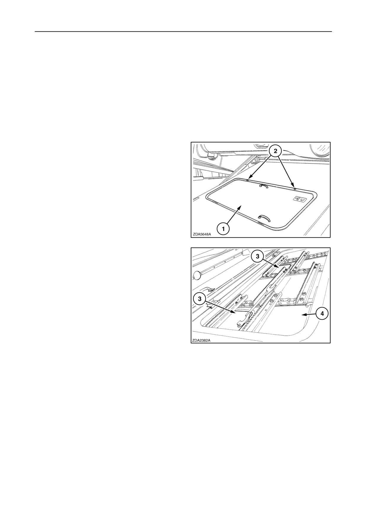
SECTION 3 - FIELD AND SITE OPERATION
Intermediate plate
Depending the type of straw elevator the
intermediate plate is equipped with evacution holes.
CX700 models: two evacuation holes.
CX800 models: three evacuation holes.
In some crops (maize), it will be necessary to remove
the covers on the intermediate plate to allow reducing
back feeding.
Proceed as follows:
1. Lower the straw elevator to the lowest position
and stop the engine.
2. Open inspection cover 1 on the top of the straw
elevator by removing two bolts 2.
34
3. Remove covers 3 on the bottom of intermediate
plate 4, using the special wrench.
4. Close the inspection cover and tighten the bolts.
35
3-36
SECTION 3 - FIELD AND SITE OPERATION
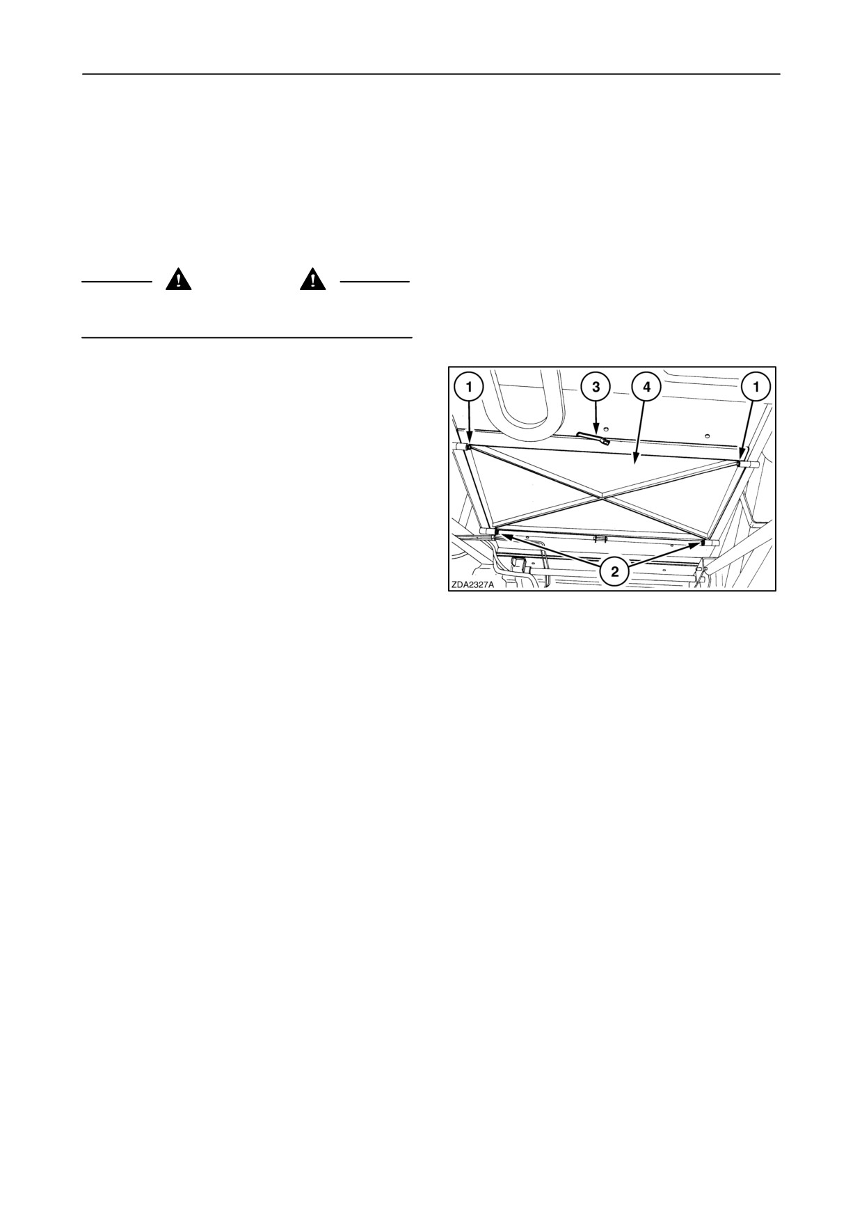
Straw elevator bottom plate (if installed)
The bottom plate middle section can be replaced by
a perforated access door
(accessory) which is
recommended when threshing beans, peas or maize
in order to obtain a cleaner grain sample.
When the perforated access door is installed, it is
possible to operate with or without the smooth bottom
plate.
CAUTION
Engage the header lifter safety latch before working
underneath the header.
To install or remove this smooth plate, proceed as
follows.
1. Remove bolts 1.
2. Loosen bolts 2.
3. Unscrew lever 3 and open the access door 4.
4. Install or remove the smooth bottom plate on top
of the perforated access door 4.
36
Limitation of the lateral float system
To prevent damage of the drive system, be sure that
the movement of the lateral float system is limited in
case of a six straw walker combine in combination
with a
6-row flip-up maize header
(MF670N or
MF675N).
3-37
SECTION 3 - FIELD AND SITE OPERATION
Straw elevator - Removal and Installation
NOTE: Be careful when doing this job: The straw
elevator weight is about 1210 kg (2668 lbs).
The tractor must have a lift capacity of minimum 2500
kg (5511 lbs) at approximately 1 m (3,3 ft) behind the
linkages.
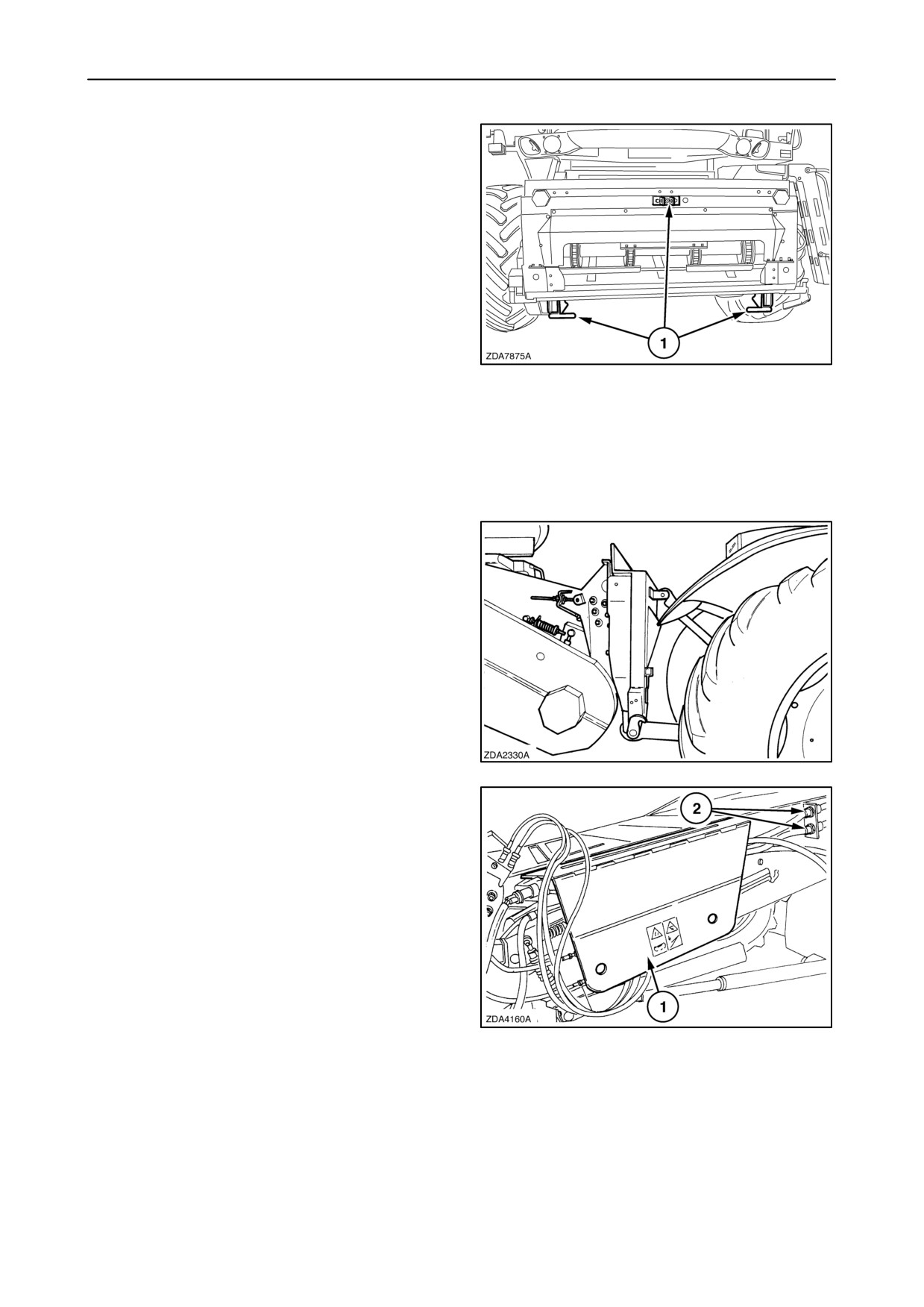
The straw elevator is fitted with three attaching points
1 which facilitate removal of the straw elevator by
means of a tractor (minimum +/- 74 kW).
37
Removal
Proceed as follows:
1. Attach the straw elevator to the tractor with the
three attaching points 1 (fig. 37) and secure the
pins with the lynch pins.
38
2. Disconnect the electric cables 2 on the left-hand
side.
3. Open shielding 1.
39
3-38
SECTION 3 - FIELD AND SITE OPERATION
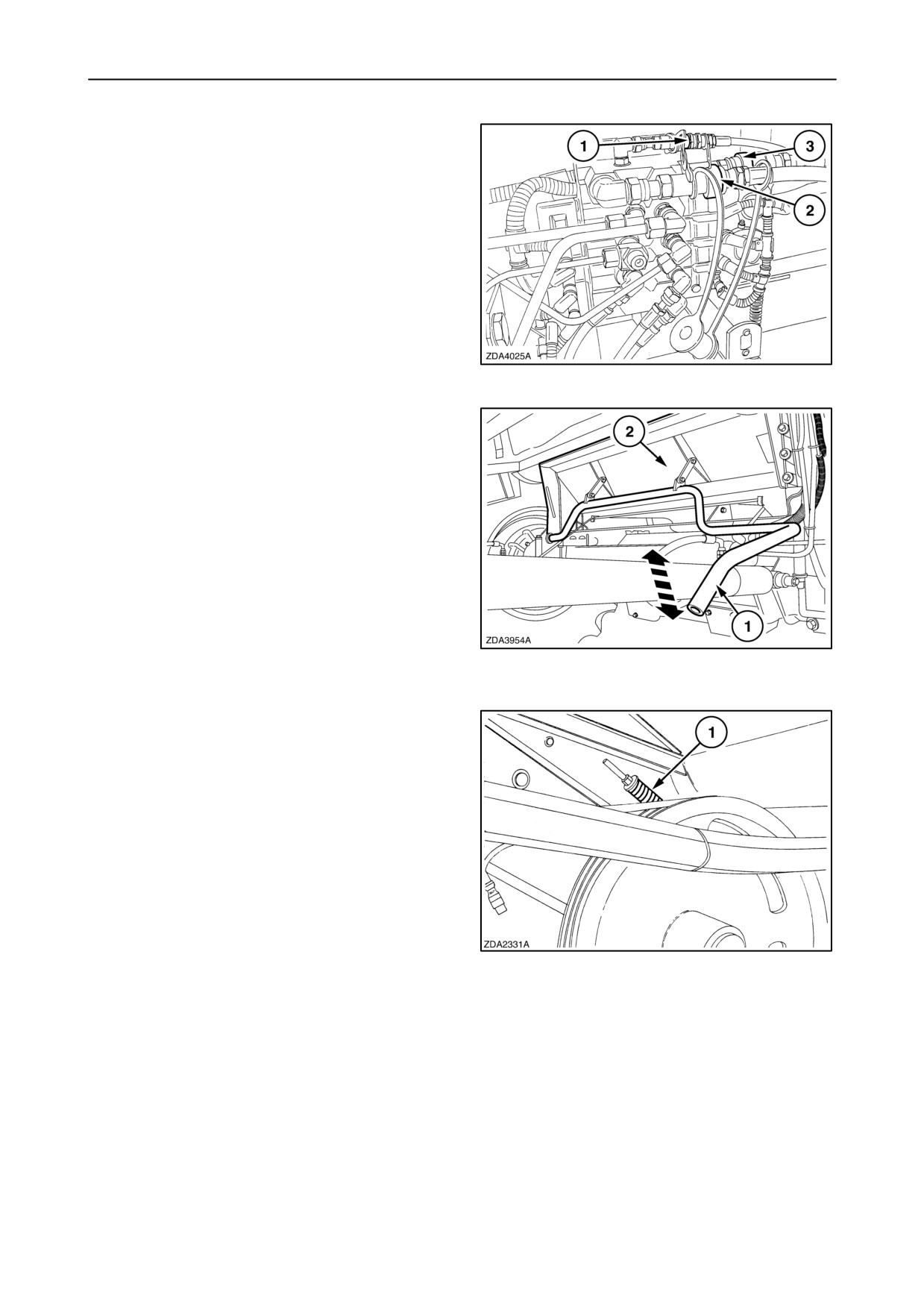
4. To disconnect the hydraulic quick-couplers,
proceed as follows:
• Disconnect first hydraulic quick-couplers 1
and 2.
• Disconnect final quick-coupler 3.
IMPORTANT: Avoid possible oil contamination by
properly fitting the blanking plugs into the hydraulic
quick-couplers.
40
5. Swing lever 1 upwards to open stone trap 2.
41
6. Remove the shielding on the right-hand side of
the straw elevator.
7. Loosen idler 1 to remove the straw elevator drive
belt.
42
3-39