New Holland CX720, CX740, CX760, CX780, CX820, CX840, CX860, CX880. Operator's Manual - page 11
SECTION 4 - LUBRICATION AND MAINTENANCE
To change the oil and/or oil filter and to wash the
suction screen, proceed as follows:
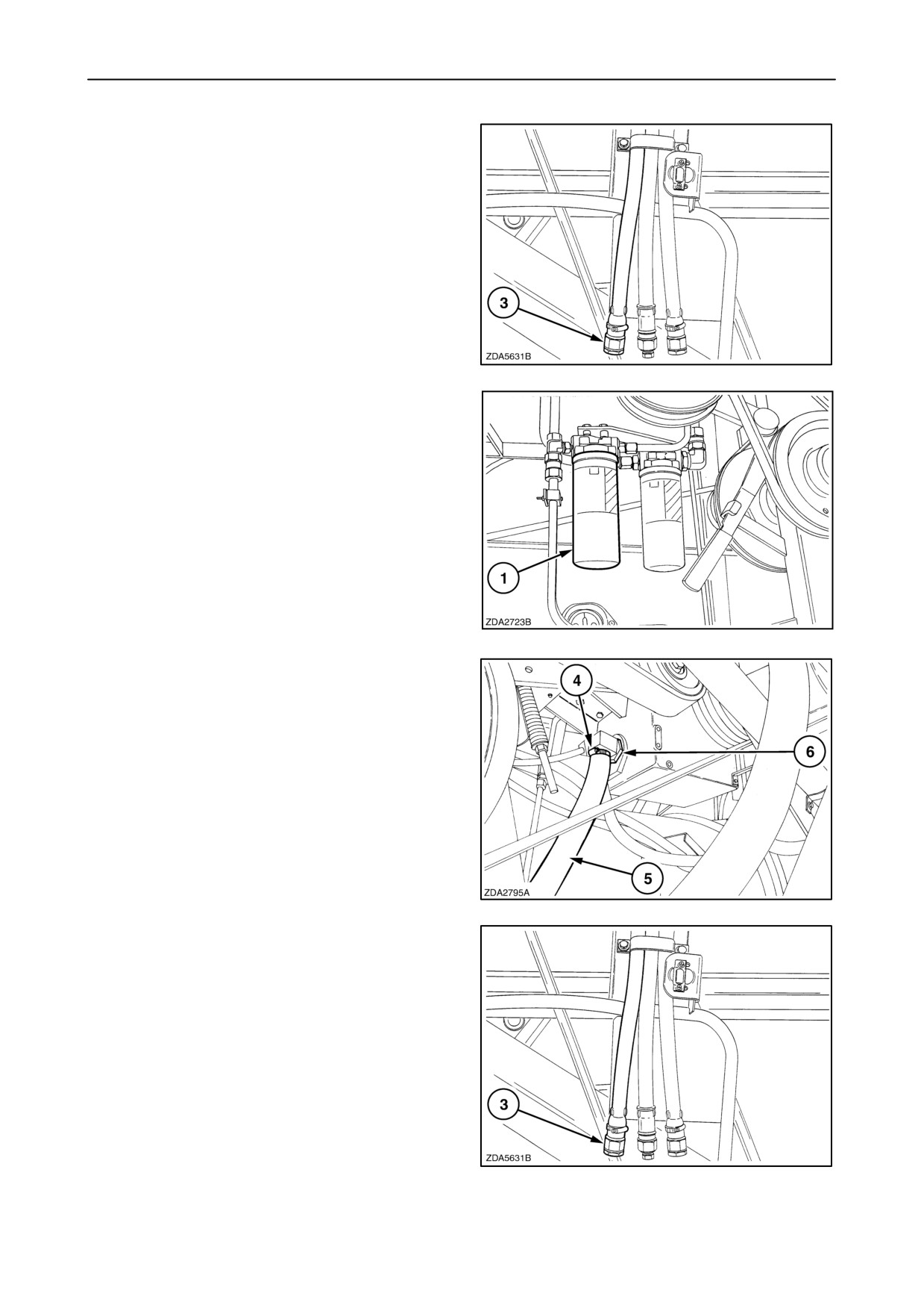
1. Drain the engine gearbox oil through hose 3 and
catch the oil in a suitable container.
96
2. Clean the area around engine gearbox oil filter 1
and remove the ”spin-on” filter.
3. Fill up a new engine gearbox oil filter with clean
oil and apply a film of oil to the seal ring.
4. Screw on the new filter by hand. Tighten firmly,
but do not use tools.
NOTE: The engine gearbox oil filter 1 can be changed
without drain the oil.
97
5. Loosen hose clamp 4, remove hose 5 and suction
screen 6.
6. Wash suction screen 6.
7. Reinstall the washed suction screen, hose 5 and
tighten hose clamp 4.
98
8. Reinstall the plug of drain hose 3.
99
4-38
SECTION 4 - LUBRICATION AND MAINTENANCE
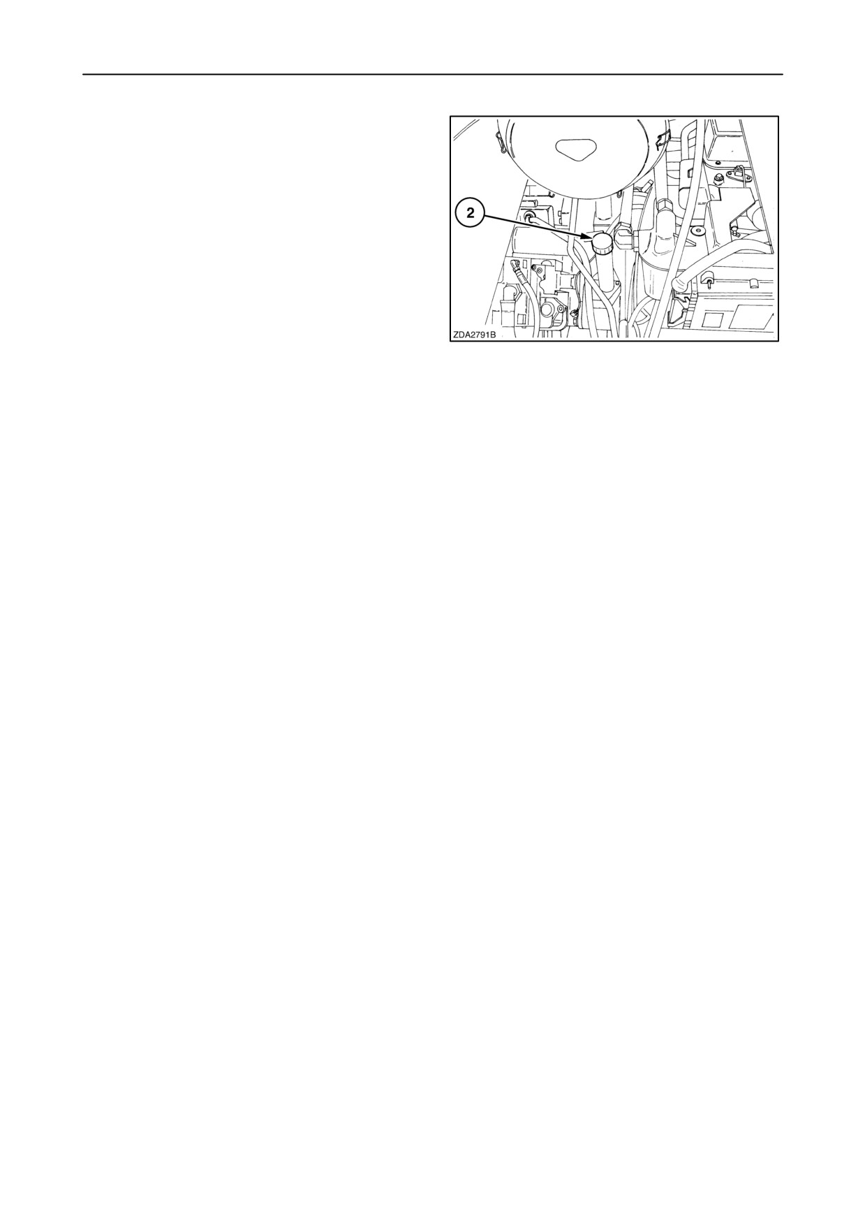
9. Remove filler cap 2 and refill the engine gearbox
with clean oil. Reinstall filler cap 2.
100
Oil capacity
The oil required to fill to the full mark on the indicator
is 11 litres (2.9 US gallons).
Oil specification
Use AMBRA HYDROSYSTEM 46 HV, NH646 H
hydraulic oil or an oil meeting the following
specification:
• DIN 51524 PART 2 HV 46
• ISO VG-46
or
Use AMBRA MULTI G (ref. NH410B) oil or an oil
meeting the following specification:
• M2C 134-D
4-39
SECTION 4 - LUBRICATION AND MAINTENANCE
TRACTION GEARBOX
Oil level
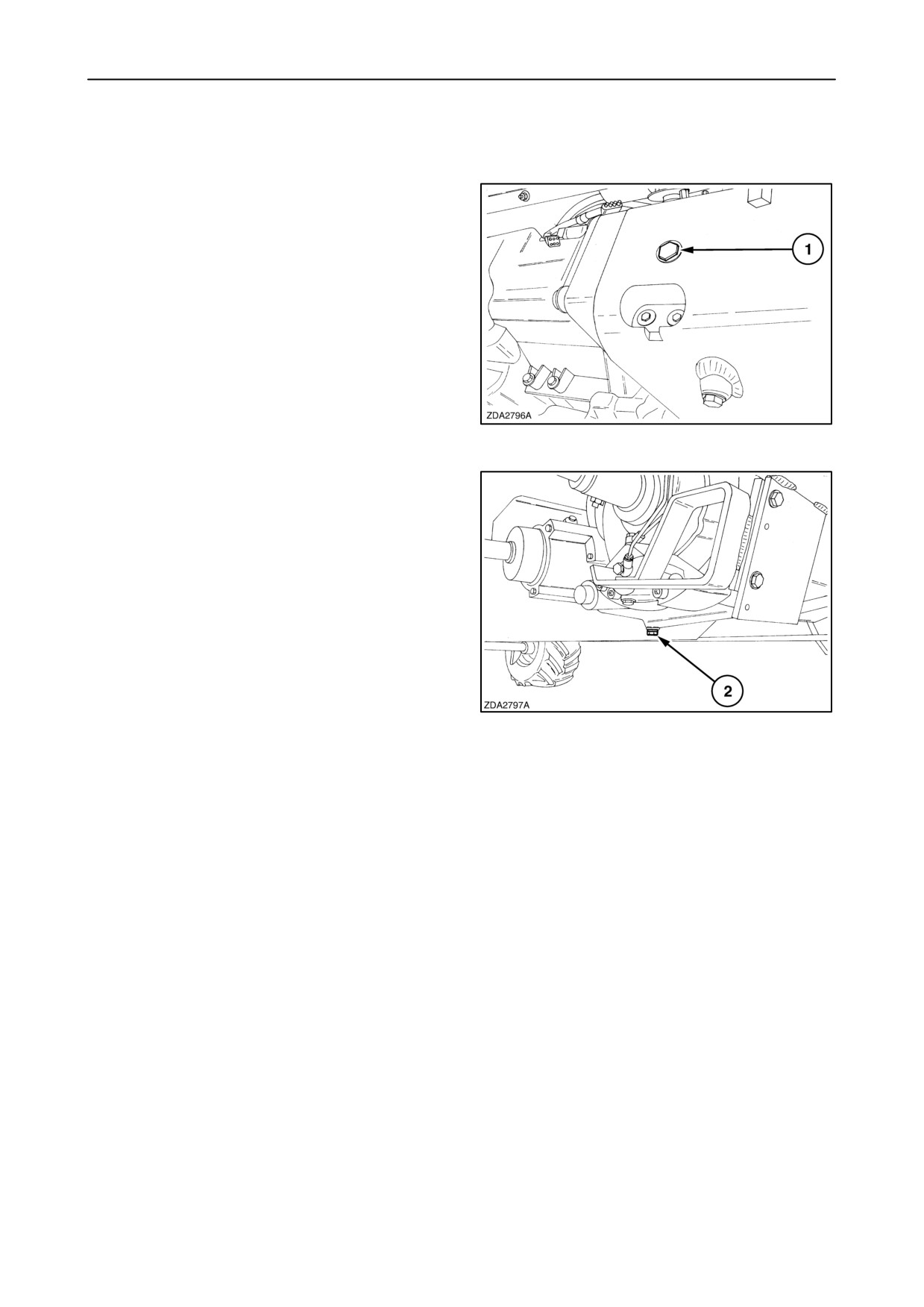
With the combine standing on a level surface, the oil
level should reach the centre of sight glass 1.
101
Oil change
The traction gearbox oil should be changed:
• After the first 100 operating hours
• Thereafter, every 600 operating hours or annually
To change the traction gearbox oil, proceed as
follows:
1. Drain the oil through plug 2 and catch the oil in a
suitable container.
2. Reinstall plug
2.
102
IMPORTANT: Clean magnetic plug
2 before
installation.
4-40
SECTION 4 - LUBRICATION AND MAINTENANCE
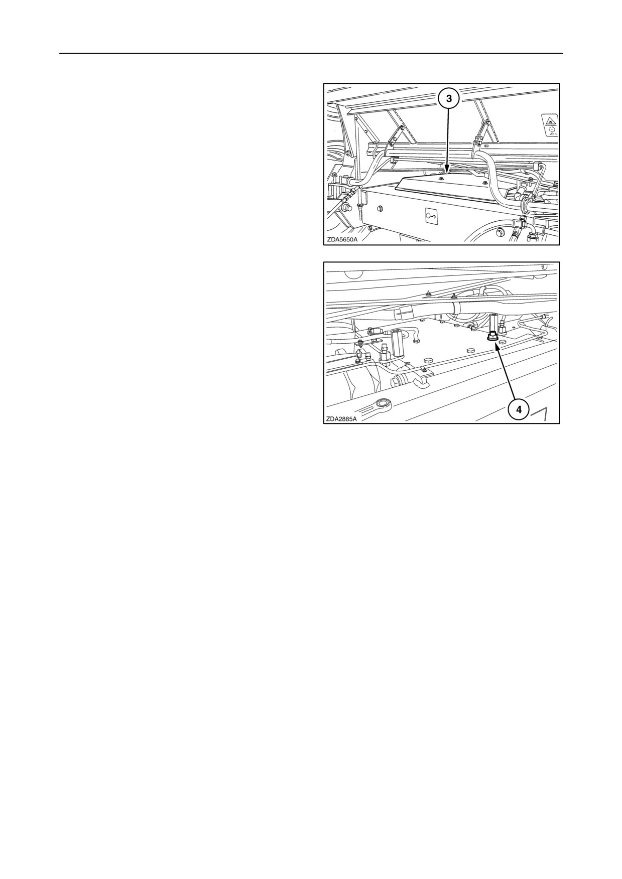
3. Remove traction gearbox cover plate 3.
103
4. Clean the area around filler/breather plug 4 and
remove the filler/breather plug.
5. Fill the traction gearbox with new oil until the oil
level reaches the right glass.
6. Reinstall filler/breather plug
4 and traction
gearbox cover plate 3.
104
Oil capacity
19 litres (5 US gallons)
Oil specification
Use AMBRA HYPOIDE 90, SAE 80W90, NH520A or
an oil meeting the following specification:
• API GL-5
• MIL-L-2105 D
4-41
SECTION 4 - LUBRICATION AND MAINTENANCE
FINAL DRIVE GEARBOXES
Oil level
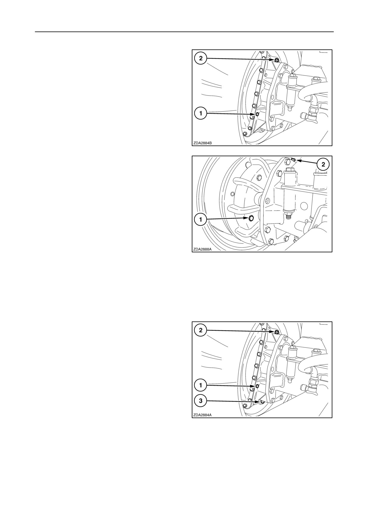
- Standard and Heavy Duty final drives 11/111:
With the combine standing on a level surface, the oil
should reach plug 1.
If necessary, add oil through filler/breather plug 2.
105
- Planetary final drives 1/13.09:
With the combine standing on a level surface, the oil
level should reach the centre of sight glass 1.
If necessary, add oil through filler/breather plug 2.
106
Oil change
The final drive gearbox oil should be changed:
• After the first 100 operating hours
• Thereafter, every
600 operating hours or
annually.
To change the standard or heavy duty final drive
gearbox oil, proceed as follows:
1. Drain the oil through plug 3 and catch the oil in a
suitable container.
2. Reinstall plug
3.
IMPORTANT: Clean magnetic plug
3 before
installation.
3. Clean the area round level plug 1, filler/breather
plug 2 and remove them.
107
4. Fill the final drive gearbox with new oil.
5. Reinstall level plug 1 and filler/breather plug 2.
4-42
SECTION 4 - LUBRICATION AND MAINTENANCE
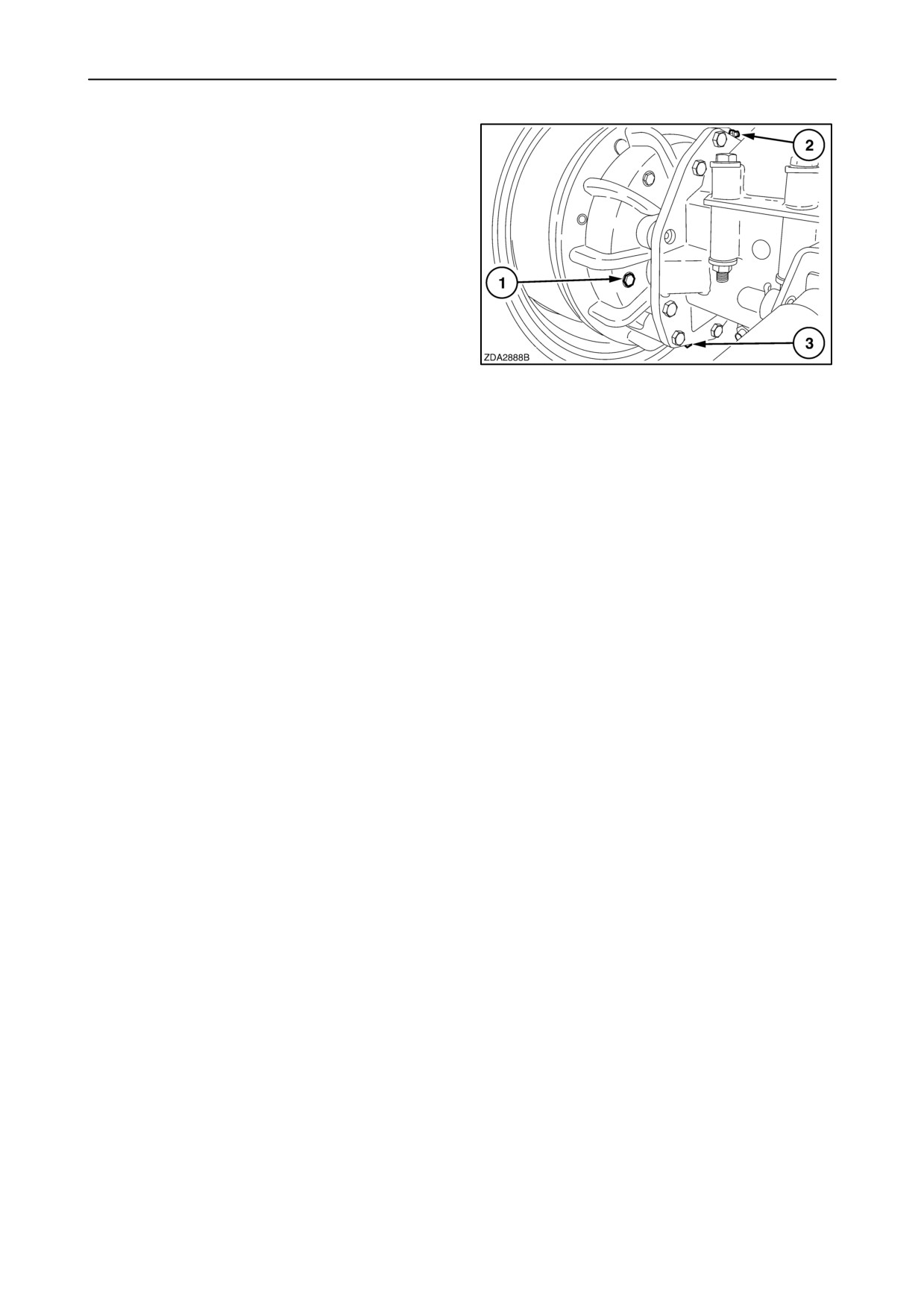
To change the planetary final drive gearbox oil,
proceed as follows:
1. Drain the oil through plug 3 and catch the oil in a
suitable container.
2. Reinstall plug
3.
IMPORTANT: Clean magnetic plug
3 before
installation.
3. Clean the area around filler/breather plug 2 and
remove them.
108
4. Fill the final drive gearbox with new oil until the oil
should reach the centre of sight glass 1.
5. Reinstall filler/breather plug 2.
Oil capacity
Standard 11/ 111 final drives : 7.2 litres
(1.9 US gal)
Heavy Duty 11/ 111 final drives : 7.85 litres
(2.07 US gal)
Planetary 1/13.09 final drives : 6.7 litres
(1.77 US gal)
Oil specification
Use AMBRA HYPOIDE 90, SAE 80W90, NH520A or
an oil meeting the following specification:
• API GL-5
• MIL-L-2105 D
4-43
SECTION 4 - LUBRICATION AND MAINTENANCE
UNLOADING DRIVE GEARBOX
Oil change
The unloading drive gearbox oil should be changed:
• After the first 100 operating hours.
• Thereafter, every
600 operating hours or
annually.
109
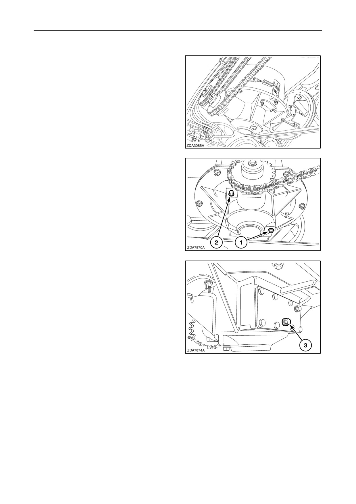
To change the oil, proceed as follows:
1. Drain the oil through plug 1 and catch the oil in a
suitable container.
2. Reinstall plug
1.
3. Clean the area round filler plug 2, level plug 3
(fig. 111) and remove them.
4. Fill the gearbox with new oil through plug 2.
110
5. Reinstall level plug 3 and filler plug 2.(fig. 110)
111
Oil capacity
0.6 litres (0.16 US gal)
Oil specification
Use AMBRA HYPOIDE 90, SAE80W90, NH520A or
an oil meeting the following specification:
• API GL-5
• MIL-L-2105 D
4-44
SECTION 4 - LUBRICATION AND MAINTENANCE
UNLOADING TUBE GEARBOX
Oil check
The unloading tube gearbox oil level should only be
checked.
• After the first 100 operating hours.
• Thereafter, every
600 operating hours or
annually.
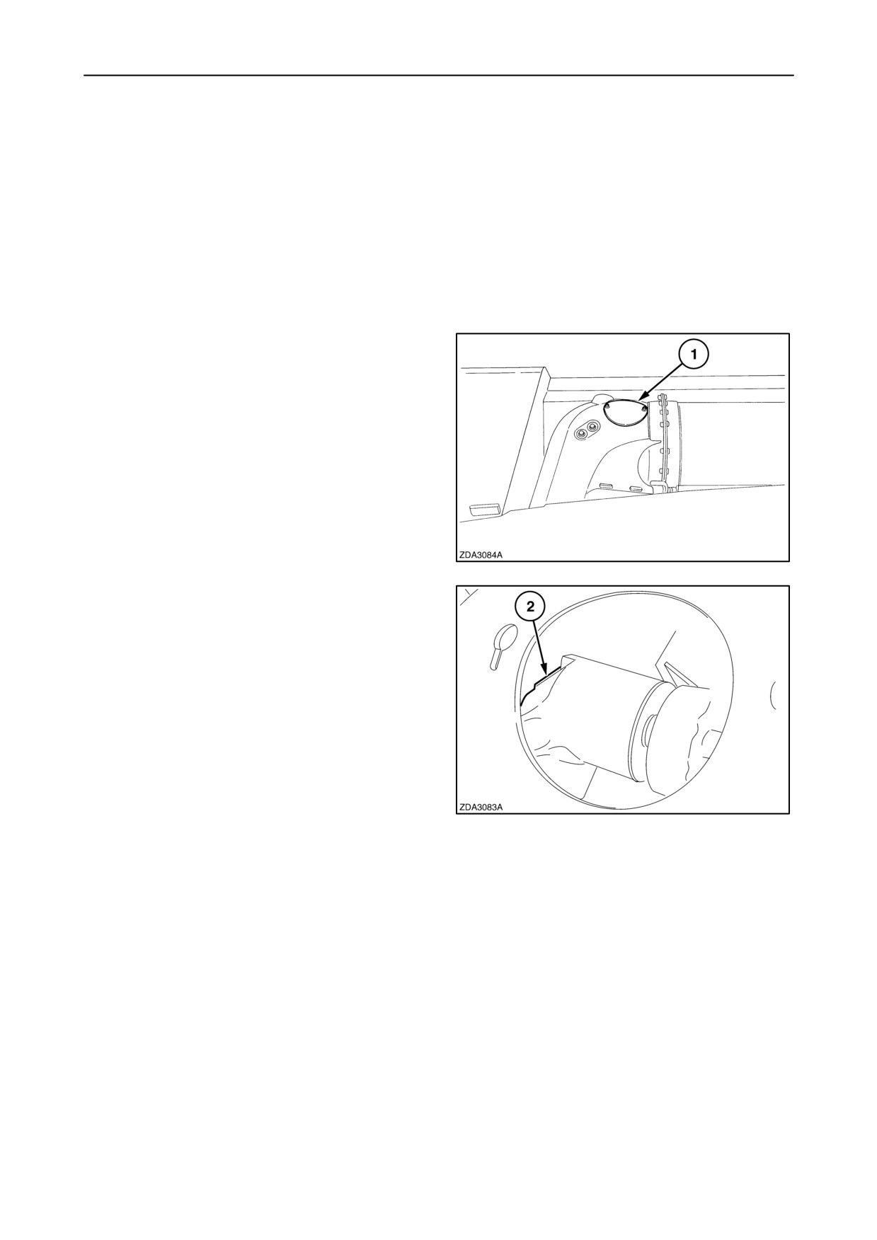
To check the oil proceed as follows:
1. Place the unloading tube in transport position.
2. Loosen the two nuts to remove cover 1.
112
3. Remove the filler plug 2 of the gearbox.
113
Oil capacity
0.3 litres (0.08 US gal)
Oil specification
Use AMBRA HYPOIDE 90, SAE 80W90, NH520A or
an oil meeting the following specification:
• API GL-5
• MIL-L-2105 D
4-45
SECTION 4 - LUBRICATION AND MAINTENANCE
BUBBLE-UP GEARBOX
Oil change
The bubble-up gearbox oil should be changed:
• After the first 100 operating hours.
• Thereafter, every
600 operating hours or
annually.
To change the oil, proceed as follows.
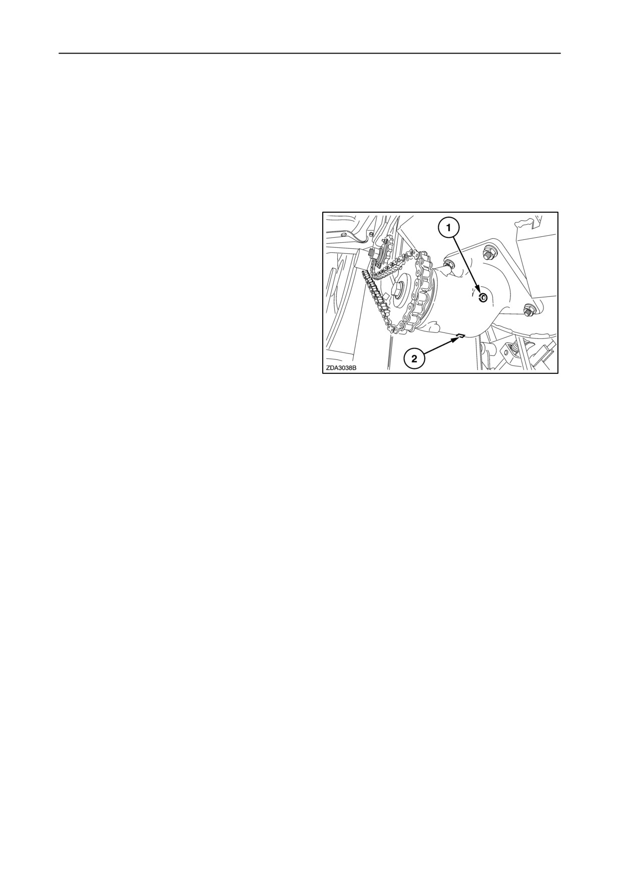
1. Drain the oil through plug 2 and catch the oil in a
suitable container.
NOTE: To drain the oil faster, clean the area round
filler plug 1 and remove it.
2. Reinstall plug
2.
3. Fill the gearbox with 0.25 litres (0.07 US gal) new
oil through plug 1.
4. Reinstall plug 1.
114
Oil capacity
0.25 litres (0.07 US gal)
Oil specification
Use AMBRA HYPOIDE 90, SAE 80W90, NH520A or
an oil meeting the following specification:
• API GL-5
• MIL-L-2105 D
4-46
SECTION 4 - LUBRICATION AND MAINTENANCE
CHAINS, THREADED RODS AND PIVOT POINTS
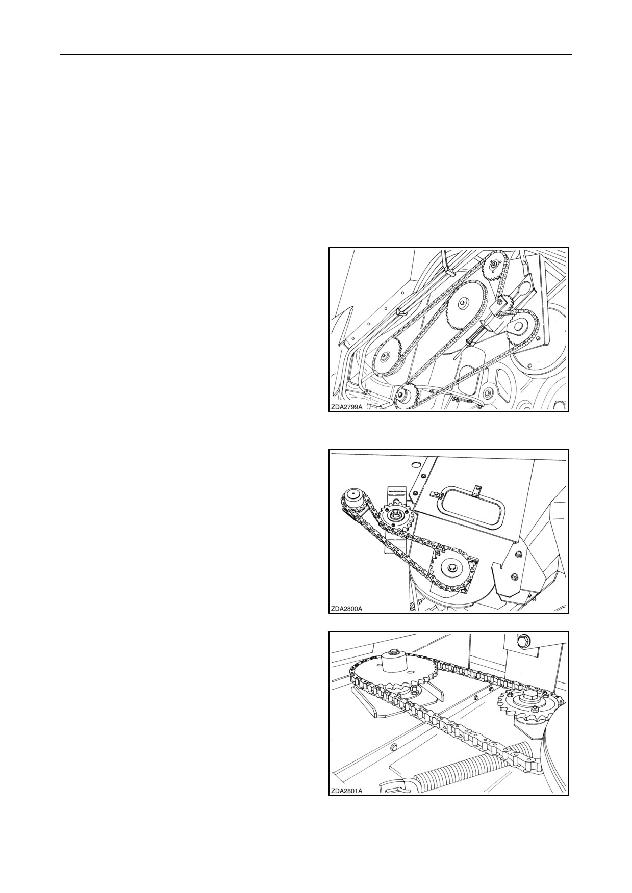
Chains
Lubricate the following chains every 100 hours.
In this way the oil will penetrate into the chains and
provide excellent protection and lubrication.
Use AMBRA HYPOIDE 90, SAE 80W90, NH520A or
a special (biodegradable) chain oil.
• Unloading drive chain
115
• Bubble up drive chain
116
• Grain elevator drive chain
117
4-47
SECTION 4 - LUBRICATION AND MAINTENANCE
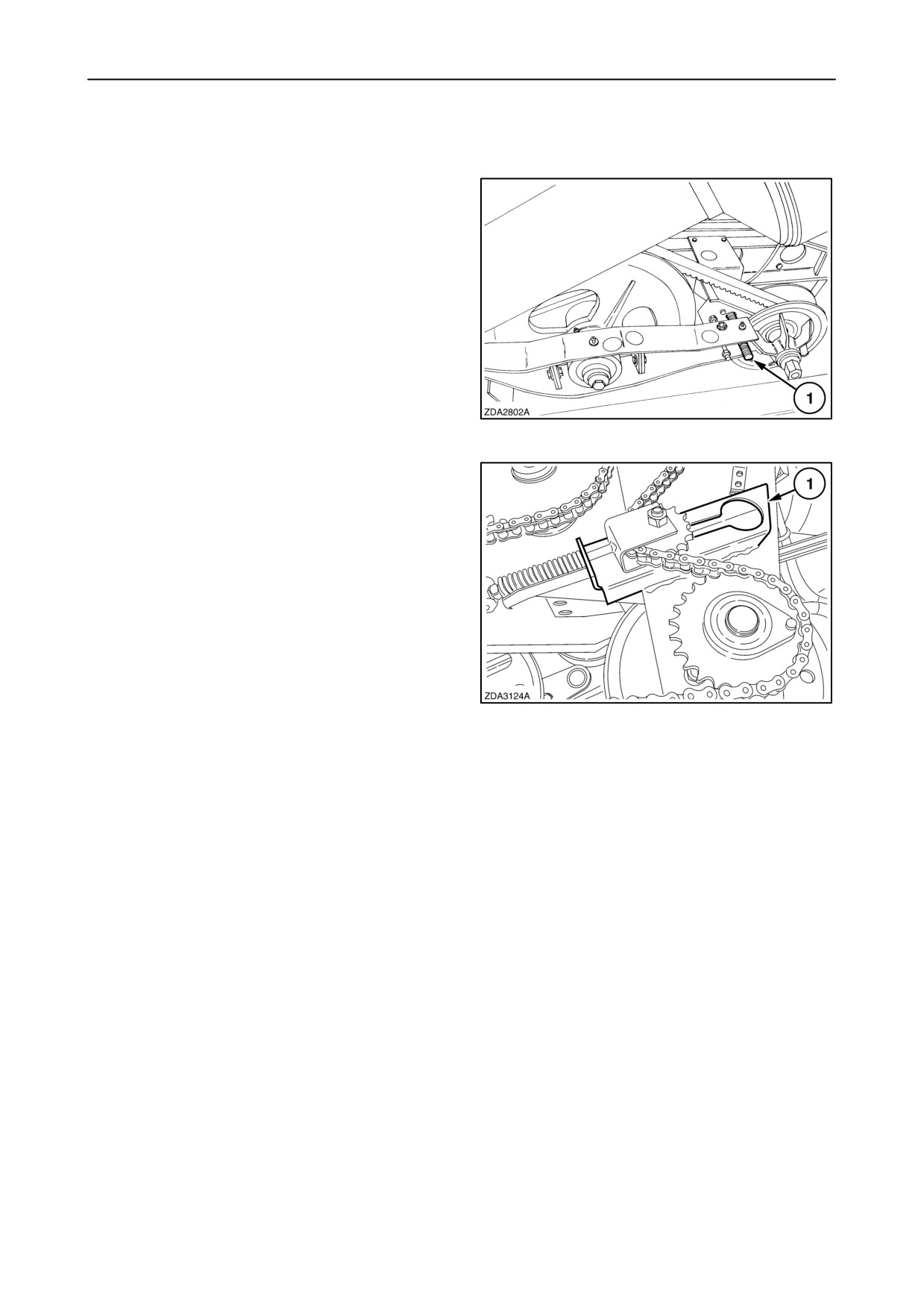
Threaded rods
Lubricate the fan variator rod 1 every 200 operating
hours.
NOTE: Lubricate all threaded rods of the spring
loaded idlers and all other threaded rods where
adjustments are carried out at least once a season.
118
Grease the unloading chain idler support 1 every 200
operating hours.
119
Pivot points
It is recommended to oil all pivot points (including
guard pivot points) which may become stiff from
corrosion or dirt every 200 operating hours.
4-48
SECTION 4 - LUBRICATION AND MAINTENANCE
BRAKE SYSTEM
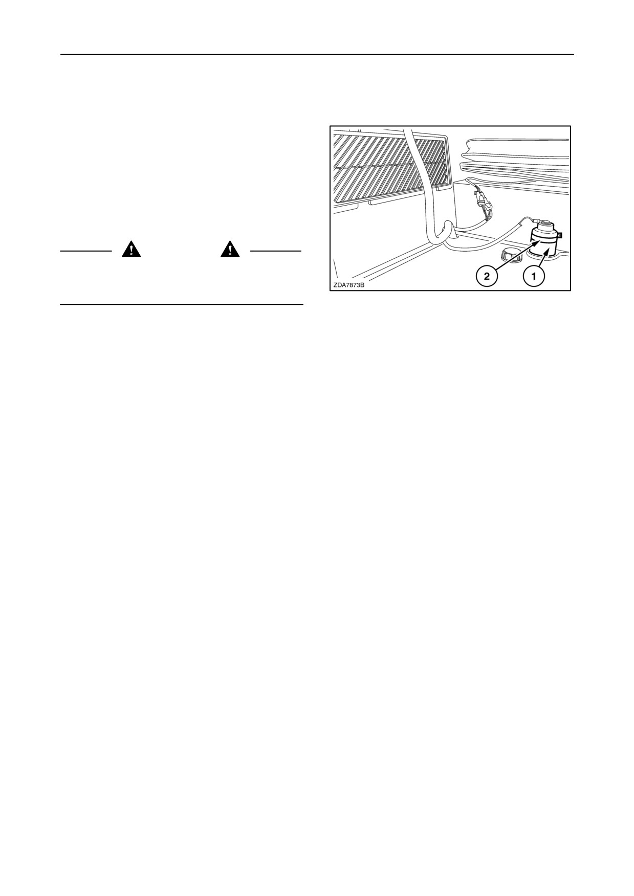
Brake fluid level
The fluid level is electrical controlled.
A warning light
(SECTION
2
“CONTROLS,
INSTRUMENTS AND OPERATION”) will illuminate
whenever the fluid is too low or the brake linings are
worn.
A mark 2 on the reservoir 1 indicates the maximum
fluid level.
CAUTION
In case of leakage or malfunction of the brake
system, immediately contact your local New Holland
dealer
120
Fluid change
The brake fluid has to be changed every two years.
When refilling the system, a special bleeding
procedure will have to be followed.
Contact your local dealer to carry out this job.
IMPORTANT: Brake fluid has a tendency to absorb
moisture and brake down over time. Therefore it
should be replaced every two years. As brake fluid
contains substances which, when mixed with engine
or other oils,create problems for recycling the oil, do
not mix oil, but collect separately.
Capacity
Reservoir: 0,25 litres (0,07 US gal.)
Entire brake system: 0,825 litres (0,21 US gal.)
Fluid specification
Use AMBRA SYNTFLUID 4, NH800A, SAE-J-1703
or a fluid meeting the following specification:
• NHTSA 116-DOT 4 or ISO 4925
4-49

SECTION 4 - LUBRICATION AND MAINTENANCE
LUBRICATION SCHEDULE
ITEM
Servicing
Amount
NEW HOLLAND
NEW
Lubricant
International
interval
unit
brand name
HOLLAND
grade
specification
specification
Grease zerks
10 h - 50 h
AMBRA GR9
NH710A
NLGI 2
M1C 137-A
100 h - 200 h
or
or
AMBRA GR75MD
NH720A
M1C 75-B
Engine (sump
Check daily
with filter)
Change
23 litres
(CNH engine)
- after first 100h
(6.08 US gal)
- every 300h or
annually
AMBRA
NH330H
SAE 15W40
API CH-4
(Iveco engine)
Check daily
CX860
or
-CX860
Change
24 litres
MASTER GOLD
ACEA E3/E5
-CX880
- after first 100h
(6.34 US gal)
HSP
- every 600h or
CX880
annually
29 litres
(7.7 US gal)
Hydraulic and
Check daily
70 litres
AMBRA
NH646H
HV 46
DIN 51524
Change
HYDROSYSTEM
Hydrostatic
(18.5 US gal)
PART 2 HV46
46 HV
system
- after first 100h
ISO VG-46
(oil+filters)
(filters only)
or
or
or
AMBRA
NH410B
M2C 134-D
- every 600h or
MULTI G
annually
(oil+filters)
Engine
Check daily
11 litres
AMBRA
NH646H
HV 46
DIN 51524
Change
(2.9 US gal)
HYDROSYSTEM
gearbox
PART 2 HV46
- after first 100h
46 HV
ISO VG -46
(filter only)
or
or
or
- every 600h or
AMBRA
annually
NH410B
MULTI G
M2C 134-D
(oil+filter)
4-50

SECTION 4 - LUBRICATION AND MAINTENANCE
ITEM
Servicing
Amount
NEW HOLLAND
NEW
Lubricant
International
interval
unit
brand name
HOLLAND
grade
specification
specification
Traction
Change
19 litres
AMBRA
NH520A
SAE 80W90
API GL-5
- after first 100h
(5 US gal)
HYPOIDE 90
gearbox
MIL-L-2105D
- every 600h or
annually
Final drives:
Change
Standard
- after first 100h
7.2 litres
AMBRA
NH520A
SAE 80W90
API GL-5
(1.9 US gal)
HYPOIDE 90
MIL-L-2105D
Heavy duty
- every 600h or
7.85 litres
(2.07 US gal)
Planetary
annually
6.7 litres
(1.77 US gal)
Unloading
Change
- after first 100h
drive gearbox
AMBRA
NH520A
SAE 80W90
API GL-5
0.6 litres
HYPOIDE 90
MIL-L-2105D
– every 600h or
(0.16 US gal)
annually
Unloading
Check only
- after first 100h
tube gearbox
0.3 litres
AMBRA
NH520A
SAE 80W90
API GL-5
– every 600h or
(0.08 US gal)
HYPOIDE 90
MIL-L-2105D
annually
Bubble-up
Change
- after first 100h
gearbox
0.25 litres
AMBRA
NH520A
SAE 80W90
API GL-5
– every 600h or
(0.07 US gal)
HYPOIDE 90
MIL-L-2105D
annually
Chains
100h
AMBRA
NH520A
SAE 80W90
API GL-5
200h
HYPOIDE 90
MIL-L-2105D
Threaded rods
200h
Pivot points
Brake system
Check daily
0.825 litres
AMBRA
NH800A
SAE J 1703
ISO 4925
Change every
(0.21 US gal)
SYNTFLUID 4
or
two years
NHTSA
116-DOT4
Cooling system
Check daily
CNH engine
50% AGRIFLU
NH900A
-
-
40 litres
50% water
- CNH engine
(10.6 US gal)
Change
- Iveco engine
CX860
- every
two
46 litres
years
(12.2 US gal)
CX880
50 litres
(13.2 US gal)
4-51
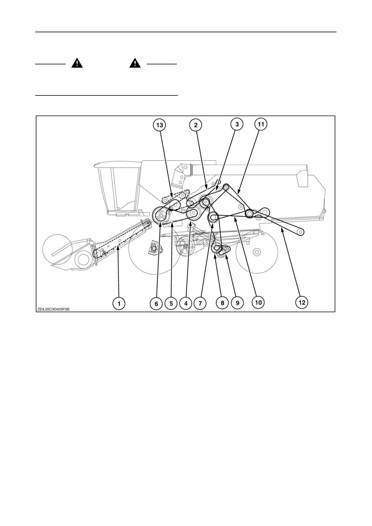
SECTION 4 - LUBRICATION AND MAINTENANCE
BELTS AND CHAINS
CAUTION
Always stop the engine, unless otherwise instructed,
before checking and/or adjusting any drive belt and
chain drive.
Drive belts and chains - Left-hand side (Self-levelling cleaning shoe)
121
IMPORTANT: Daily check all belt and chain tensions
to ensure optimum operation.
1. Straw elevator chain
8. Cleaning shoe drive belt
2. Unloading drive belt
9. Left-hand returns auger and returns cross auger
drive belt
3. Main drive belt (engine - straw flow beater)
10. Straw walker drive belt
4. Drum variator drive belt
11. Chopper front drive belt (if installed)
5. Drum drive belt
12. Chopper rear drive belt (if installed)
6. Beater drive belt
13. Unloading drive chain
7. Cleaning shoe intermediate shaft drive belt
4-52
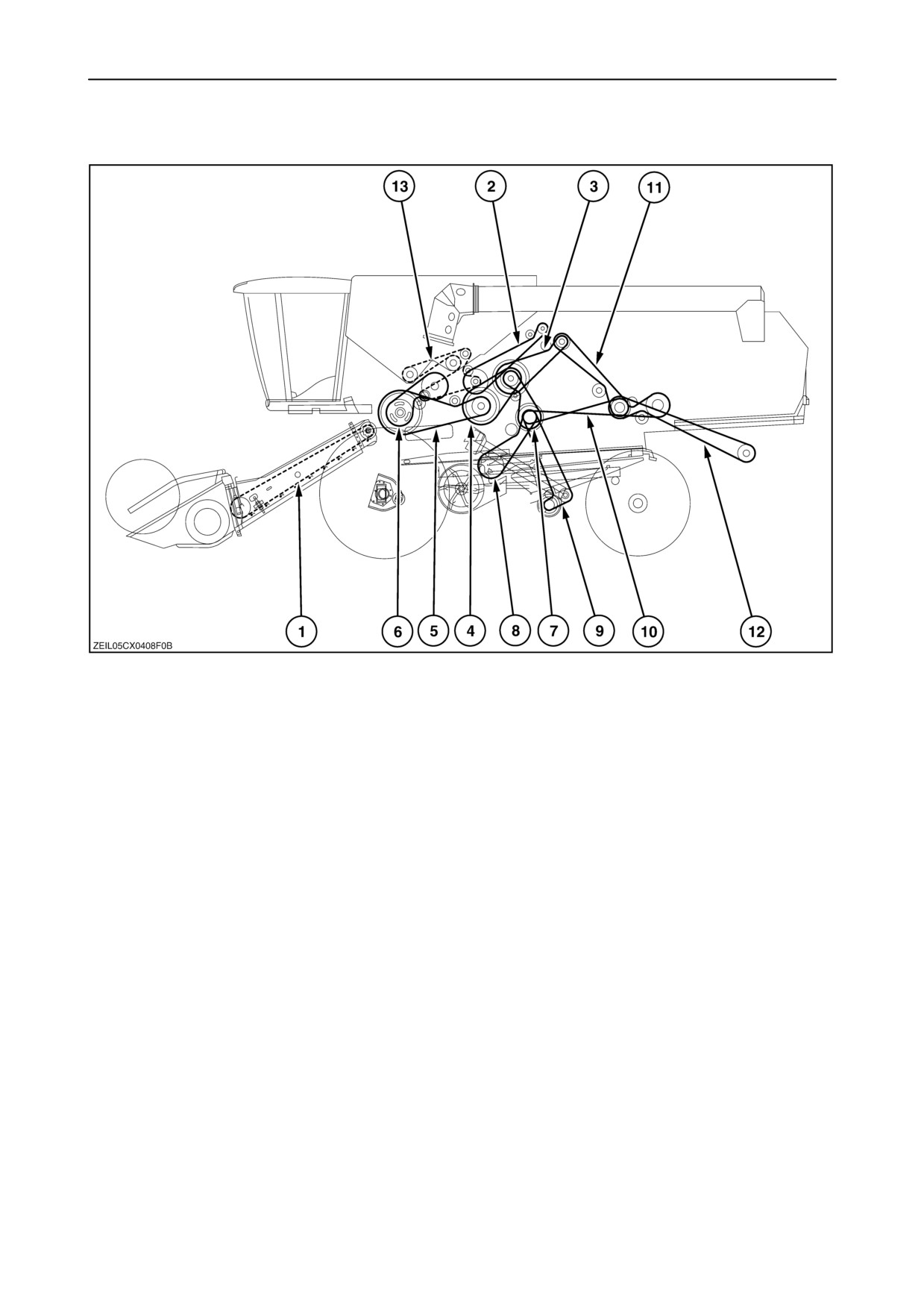
SECTION 4 - LUBRICATION AND MAINTENANCE
Drive belts and chains - Left-hand side (Fixed cleaning shoe)
122
IMPORTANT: Daily check all belt and chain tensions
to ensure optimum operation.
1. Straw elevator chain
10. Straw walker drive belt
2. Unloading drive belt
11. Chopper front drive belt (if installed)
3. Main drive belt (engine - straw flow beater)
12. Chopper rear drive belt (if installed)
4. Drum variator drive belt
13. Unloading drive chain
5. Drum drive belt
6. Beater drive belt
7. Cleaning shoe intermediate shaft drive belt
8. Cleaning shoe drive belt
9. Left-hand returns auger and returns cross auger
drive belt
4-53
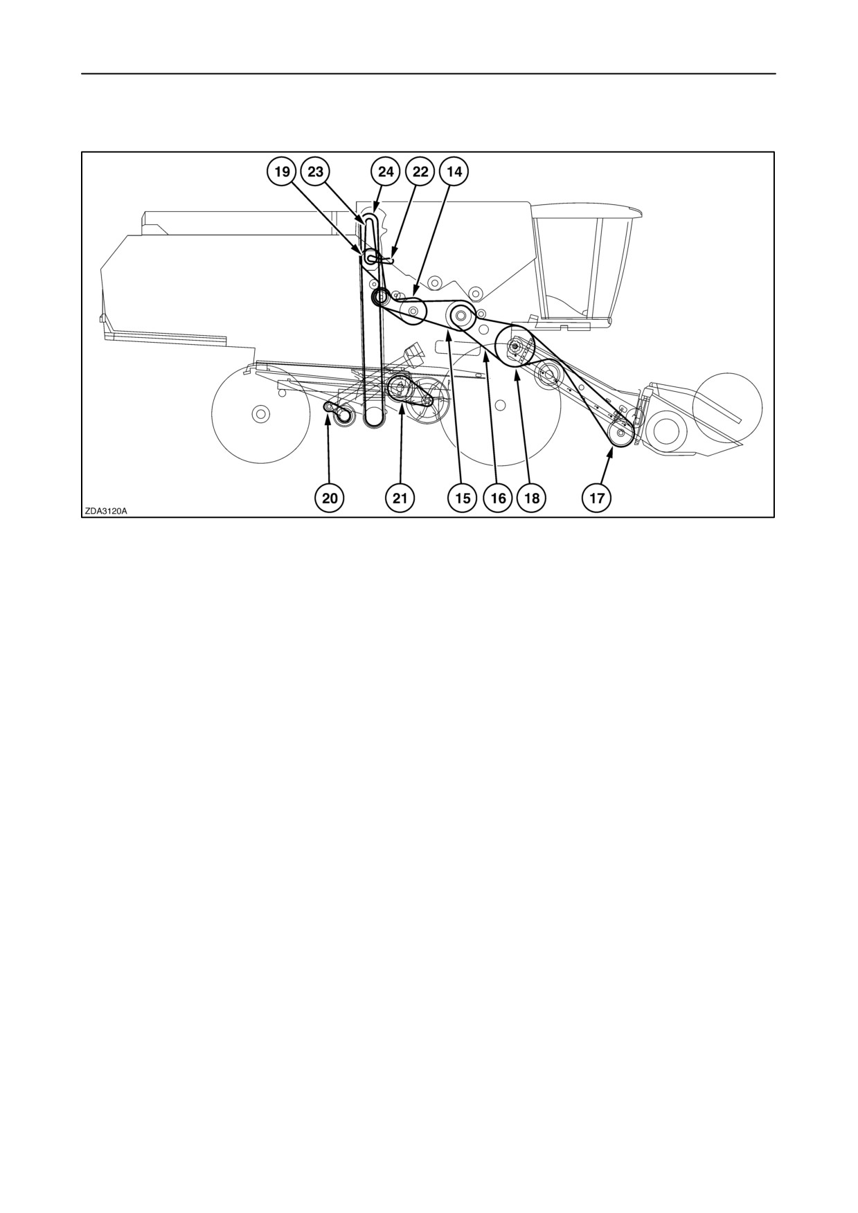
SECTION 4 - LUBRICATION AND MAINTENANCE
Drive belts and chains - Right-hand side
123
14. Rotary separator drive belt
19. Grain elevator intermediate shaft drive belt
15. Header and straw elevator intermediate drive belt
20. Right-hand returns auger drive belt
16. Straw elevator drive belt (cereals equipment)
21. Fan variator drive belt
17. Header drive belt (cereals equipment)
22. Bubble-up drive chain
23. Grain elevator drive chain
18. Header and straw elevator drive belt (maize
equipment)
24. Grain elevator chain
4-54
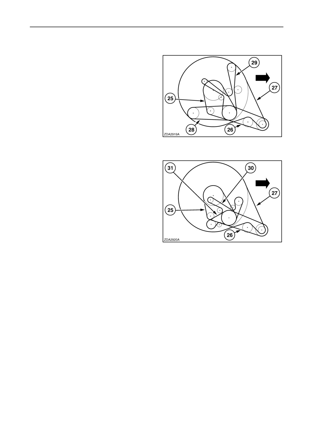
SECTION 4 - LUBRICATION AND MAINTENANCE
Drive belts - Engine compartment
CNH Engine
(CX720-740-760-780-820-840)
25. Engine fan drive belt
26. Rotary dust screen intermediate shaft drive belt
27. Rotary dust screen drive belt
28. Air compressor belt
29. Alternator, Water pump and Air conditioning
compressor drive belt
124
IVECO Engine
(CX860-880)
25. Engine fan drive belt
26. Rotary dust screen intermediate shaft drive belt
27. Rotary dust screen drive belt
30. Alternator and water pump drive belt
31. Air conditioning compressor drive belt
125
4-55
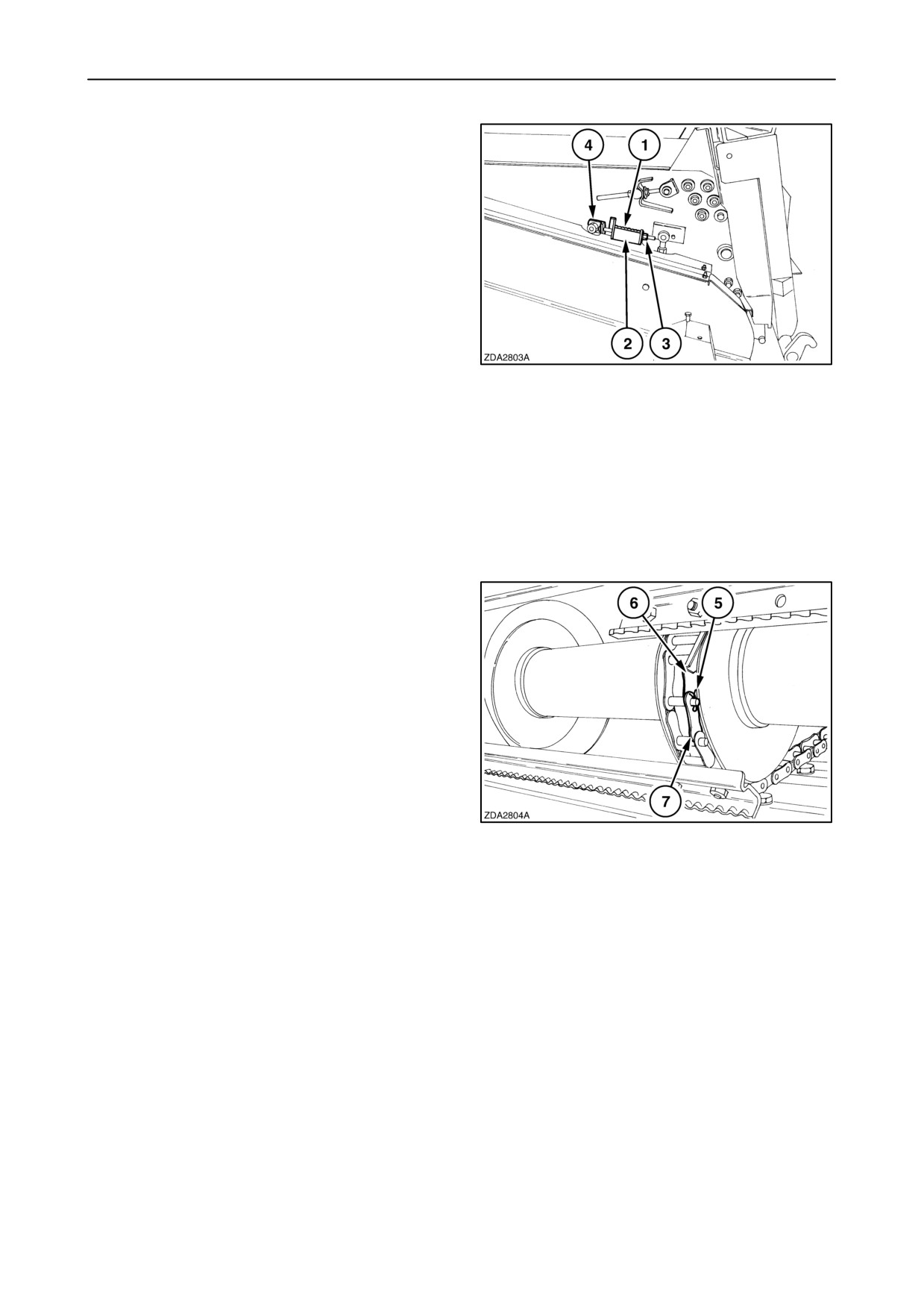
SECTION 4 - LUBRICATION AND MAINTENANCE
1.
Straw elevator chain
The straw elevator chain is factory fitted so there is
a minimal distance between the header auger and the
straw elevator chain to obtain a proper feeding.
IMPORTANT: It is required to check the straw
elevator chain tension within the first 50 hours to
prevent chain damage.
The tension of the straw elevator chain is kept
constant by springs 1 on both sides of the straw
elevator which pulls mounting supports 4 of the lower
shaft forward.
126
The chain tension is correct:
spring length 1 = indicator plate length 2.
Adjust with nuts 3.
As the chain stretches, the supports will gradually
move towards the end of the slots.
In this case, remove an offset link of the three chains
and readjust the chain tension.
Proceed as follows:
1. Turn the straw elevator chain until the connecting
links of the chains are at the front opening.
2. Loosen nuts 3 (fig. 126) on both sides of the straw
elevator to slacken the straw elevator chain.
3. Move the straw elevator lower shaft to the rear.
4. Remove cotter pins 5 and open chains 6.
5. Remove half a link 7 of each chain.
127
6. Reassemble chains 6 and install cotter pins 5 in
the right direction and bend the leys of the cotter
pins close to the pen.
7. Readjust the chain tension as described in the
beginning of this paragraph.
4-56
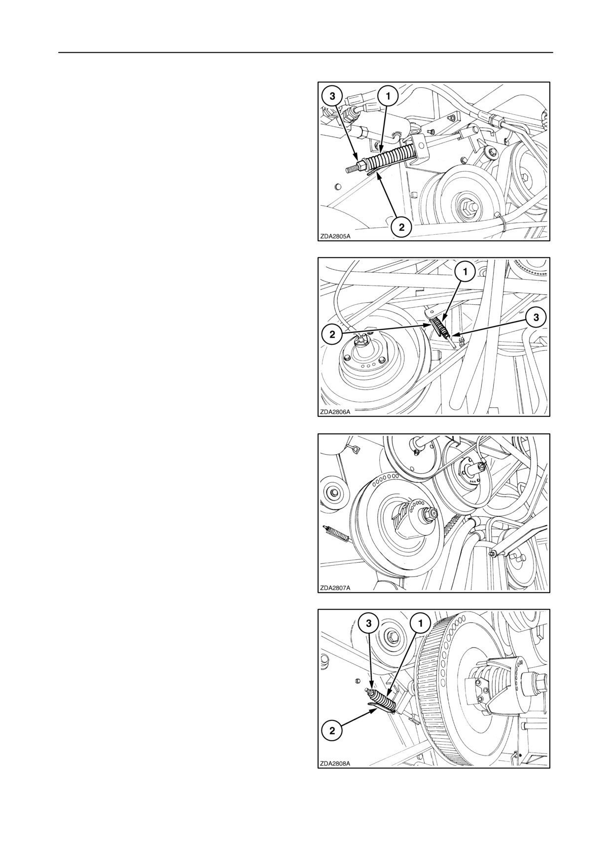
SECTION 4 - LUBRICATION AND MAINTENANCE
2.
Unloading drive belt
The belt tension is correct :
spring length 1 = indicator plate length 2.
Adjust with nut 3.
128
3.
Main drive belt
(engine - Straw Flow Beater SFB)
The belt tension is correct :
spring length 1 = indicator plate length 2.
Adjust with nut 3.
129
4.
Drum variator drive belt
The drum variator drive belt is tensioned
automatically and does not need to be adjusted.
130
5.
Drum drive belt
The belt tension is correct :
spring length 1 = indicator plate length 2.
Adjust with nut 3.
131
4-57
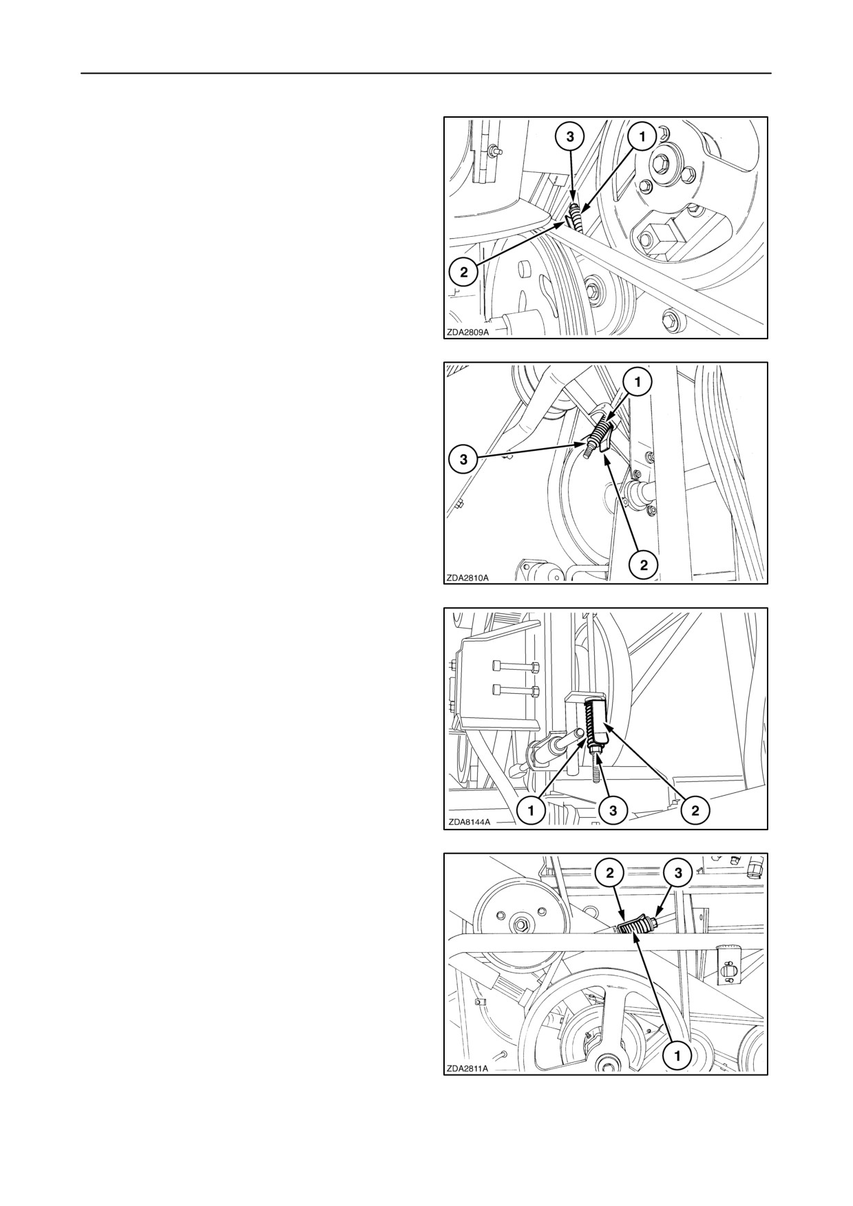
SECTION 4 - LUBRICATION AND MAINTENANCE
6.
Beater drive belt
The belt tension is correct :
spring length 1 = indicator plate length 2.
Adjust with nut 3.
132
7.
Self-levelling cleaning shoe intermediate
shaft drive belt
The belt tension is correct :
spring length 1 = indicator plate length 2.
Adjust with nut 3.
133
7.
Fixed cleaning shoe intermediate shaft
drive belt
The belt tension is correct :
spring length 1 = indicator plate length 2.
Adjust with nut 3.
134
8.
Self-levelling cleaning shoe drive belt
The belt tension is correct :
spring length 1 = indicator plate length 2.
Adjust with nut 3.
135
4-58
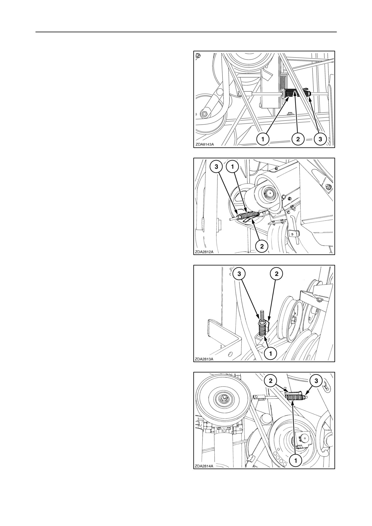
SECTION 4 - LUBRICATION AND MAINTENANCE
8.
Fixed cleaning shoe drive belt
The belt tension is correct :
spring length 1 = indicator plate length 2.
Adjust with nut 3.
136
9.
Left-hand returns auger and returns cross
auger drive belt
The belt tension is correct :
spring length 1 = indicator plate length 2.
Adjust with nut 3.
137
10. Straw walker drive belt
The belt tension is correct :
spring length 1 = indicator length 2.
Adjust with nut 3.
138
11. Chopper front drive belt (if installed)
The belt tension is correct :
spring length 1 = indicator length 2.
Adjust with nut 3.
139
4-59
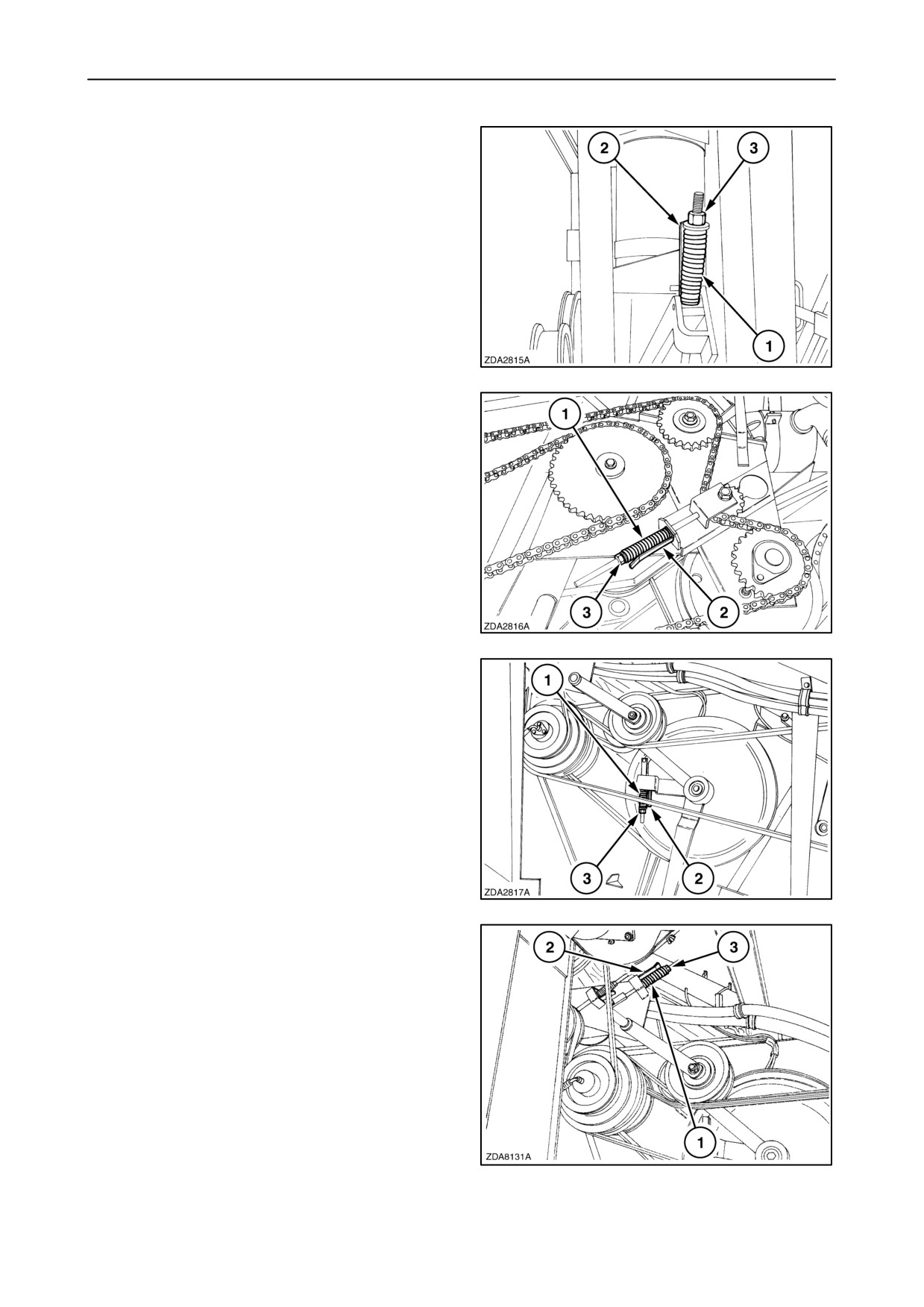
SECTION 4 - LUBRICATION AND MAINTENANCE
12. Chopper rear drive belt (if installed)
The belt tension is correct :
spring length 1 = indicator plate length 2.
Adjust with nut 3.
140
13. Unloading drive chain
The belt tension is correct :
spring length 1 = indicator length 2.
Adjust with nut 3.
141
14. Rotary separator drive belt
The belt tension is correct:
spring length 1 = indicator length 2.
Adjust with nut 3.
142
15. Header and straw elevator intermediate
drive belt
The belt tension is correct:
spring length 1 = indicator length 2
Adjust with nut 3.
143
4-60
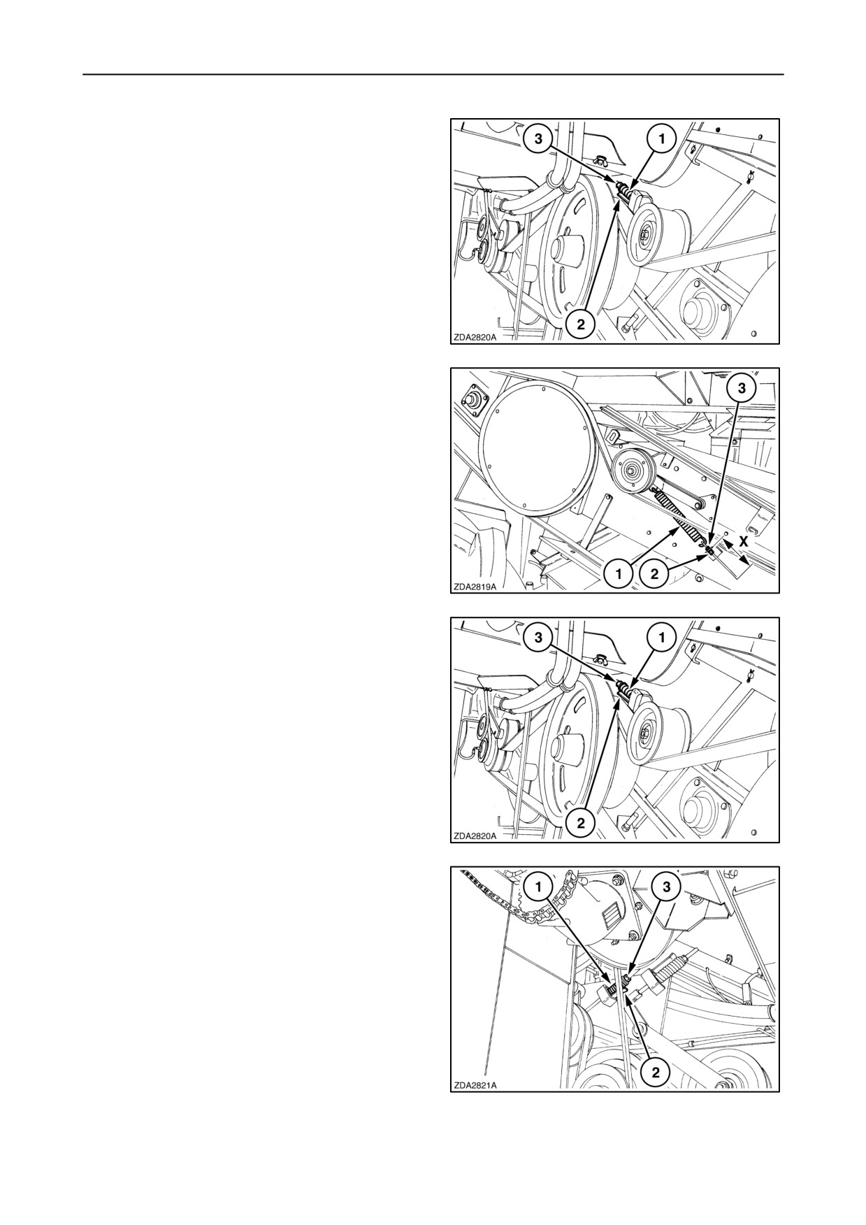
SECTION 4 - LUBRICATION AND MAINTENANCE
16. Straw elevator drive belt
(cereals equipment)
2 HB drive belt
The belt tension is correct:
spring length 1 = indicator length 2
Adjust with nut 3.
144
17. Header drive belt (cereals equipment)
2 HB drive belt
The belt tension is correct:
spring length 1= thread length X= 153 mm - 157mm
(6-2/85” - 6-2/11”).
Adjust with nut 2 and lock with nut 3.
145
18. Header and straw elevator drive belt.
(maize equipment)
4 HB drive belt
The belt tension is correct :
spring length 1 = indicator length 2
Adjust with nut 3.
146
19. Grain elevator intermediate shaft drive belt
The belt tension is correct :
spring length 1 = indicator length 2
Adjust with nut 3.
147
4-61
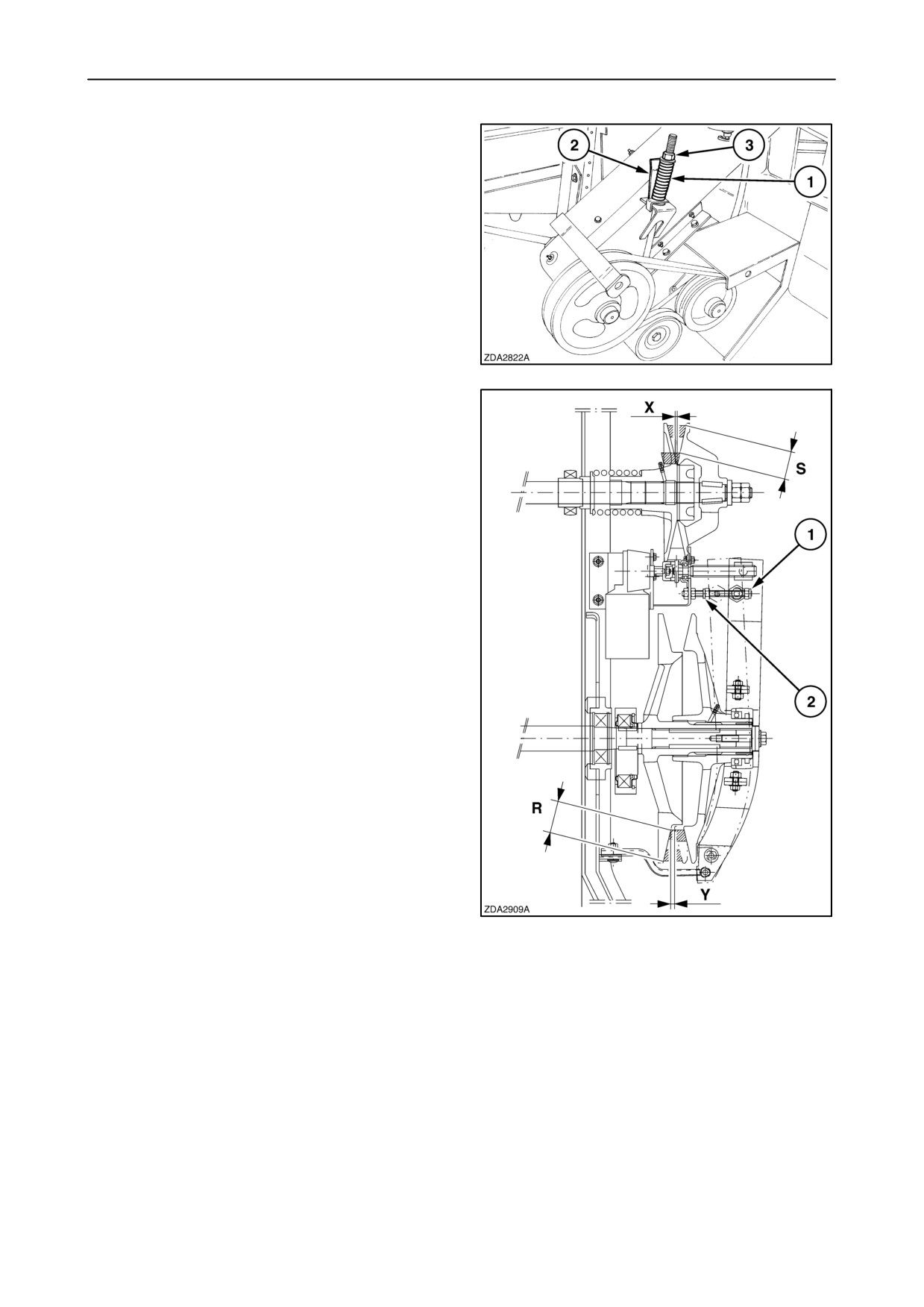
SECTION 4 - LUBRICATION AND MAINTENANCE
20. Right-hand returns auger drive belt
(if installed)
The belt tension is correct :
spring length 1 = indicator length 2
Adjust with nut 3.
148
21. Cleaning fan variator drive belt
The belt tension needs no adjustment.
Regularly check and if necessary adjust the variator.
Checking and adjusting
To check the variator, proceed as follows:
1. Start the engine
,engage the threshing
mechanism and move the fan variator to
MINIMUM. Stop the engine.
2. Measure distance
“X” between the driven
sheaves (fan shaft) and belt depth “R” on the
drive sheaves.
3. Clearance “X” should be minimum 1 mm (3/64”)
or the belt depth “R” should be maximum 39 - 41
mm (1-1/2” - 1-5/8”).
4. If necessary, adjust with nut 1 and proceed with
step 1.
5. Start the engine, engage the threshing
mechanism and move the fan variator to
MAXIMUM. Stop the engine.
6. Measure distance
“Y” between the driver
sheaves and belt depth “S” on the driven sheaves
(fan shaft).
149
7. Clearance “Y” should be minimum 1 mm (3/64”)
or the belt depth “S” should be maximum 52 - 54
mm (2-3/64” - 2-1/8”).
8. If necessary, adjust with nut 2 and proceed with
step 5.
In case of a stretched belt, the belt loop around the
sheaves may be allowed to extend maximum 3 mm
(1/8”) beyond the edge of the sheaves.
4-62
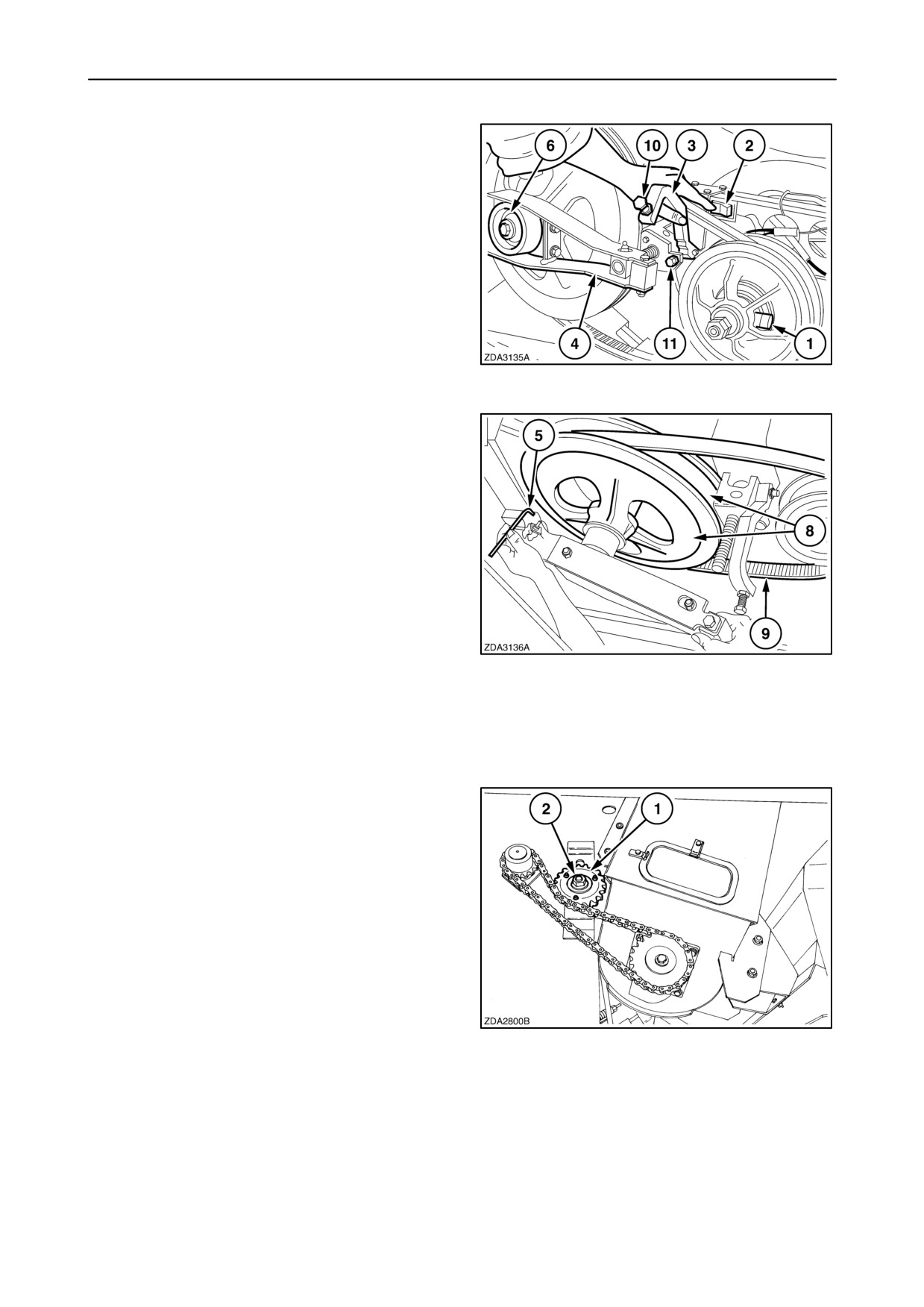
SECTION 4 - LUBRICATION AND MAINTENANCE
Low speed fan variator kit (If installed)
To change the variator sheaves and belt, proceed as
follows:
1.
Start the engine and engage the threshing
mechanism.
2.
Move the fan variator speed to maximum.
3.
Stop the engine.
4.
Install a restrictor 1 so the fan sheave, which is
spring loaded, can not move back.
5.
Plug in 12 volt DC connector.
150
6.
Open the variator (press switch 2) and hold up
pawl 3 until variator arm 4 is free.
7.
Pull out pin 5 to remove the variator arm.
8.
Remove bolt 6.
9.
Remove the two sheaves 8 and belt 9.
10. Install the other sheaves and belt.
11. Install bolt 6 and tighten to 50 Nm (37 ft lbs).
12. Install the variator arm and secure in place with
pin 5.
13. Close the variator (press switch 2) while turning
the pulley by hand until it is possible to remove
restrictor 1.
151
14. Remove the connector.
15. Adjust bolts 10 and 11 as explained in previous
paragraph headed ”Checking and adjusting”.
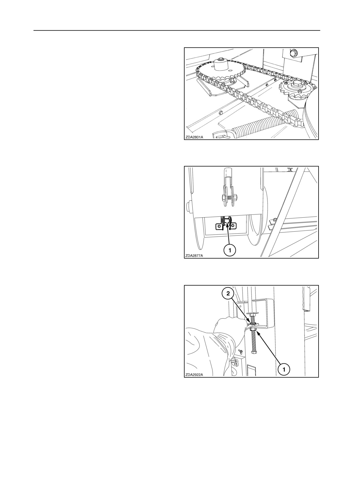
22. Bubble-up drive chain
The chain tension can be adjusted with sprocket 1.
Loosen nut 2 to move sprocket 1.
152
4-63
SECTION 4 - LUBRICATION AND MAINTENANCE
23. Grain elevator drive chain
The chain is tensioned with a spring loaded sprocket
and does not need any adjustment.
153
24. Grain elevator chain
The tension of grain elevator chain 1 is correct when
it is just possible to move a link laterally across the
lower sprocket by hand.
NOTE: Check the tension of the chain every 50
hours.
154
The tension of the grain elevator chain can be
adjusted at the rear of the grain elevator:
Loosen jam nut 1, adjust grain elevator chain tension
with nut 2. Tighten jam nut 1.
155
4-64
SECTION 4 - LUBRICATION AND MAINTENANCE
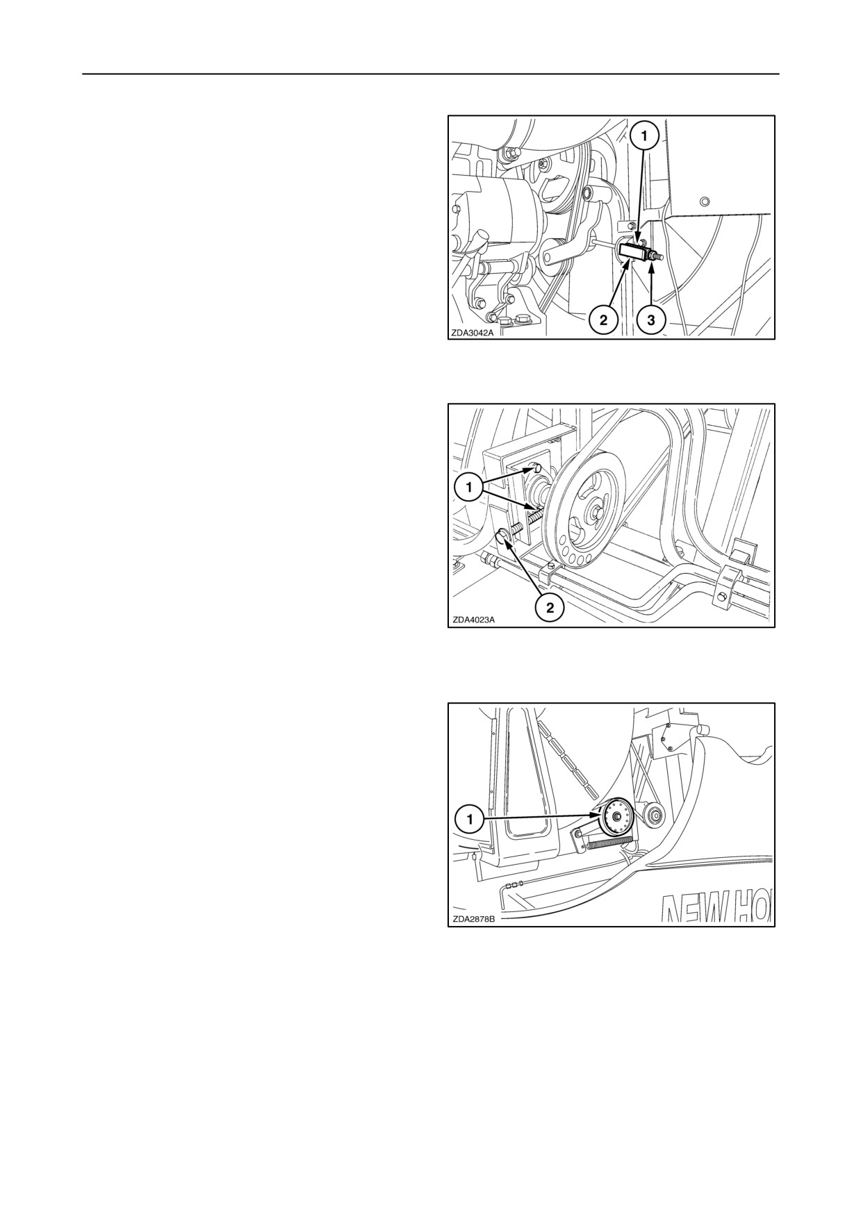
25. Engine fan drive belt
The belt tension is correct :
spring length 1 = indicator plate length 2.
Adjust with nut 3.
156
26. Rotary dust screen intermediate shaft
drive belt
The belt tension is correct :
Applying a force of 23 N (5.17 lbf) on the midpoint of
the belt between the two pulleys, should deflect the
belt 3 mm (1/8”).
To adjust the belt tension, proceed as follows:
1. Loosen nuts 1.
2. Tighten bolt 2 to obtain the correct belt tension.
The bearing housing moves in slotted holes.
3. Tighten nuts 1.
157
27. Rotary dust screen drive belt
The belt is tensioned with spring loaded idler 1 and
does not need any adjustment.
158
4-65
SECTION 4 - LUBRICATION AND MAINTENANCE
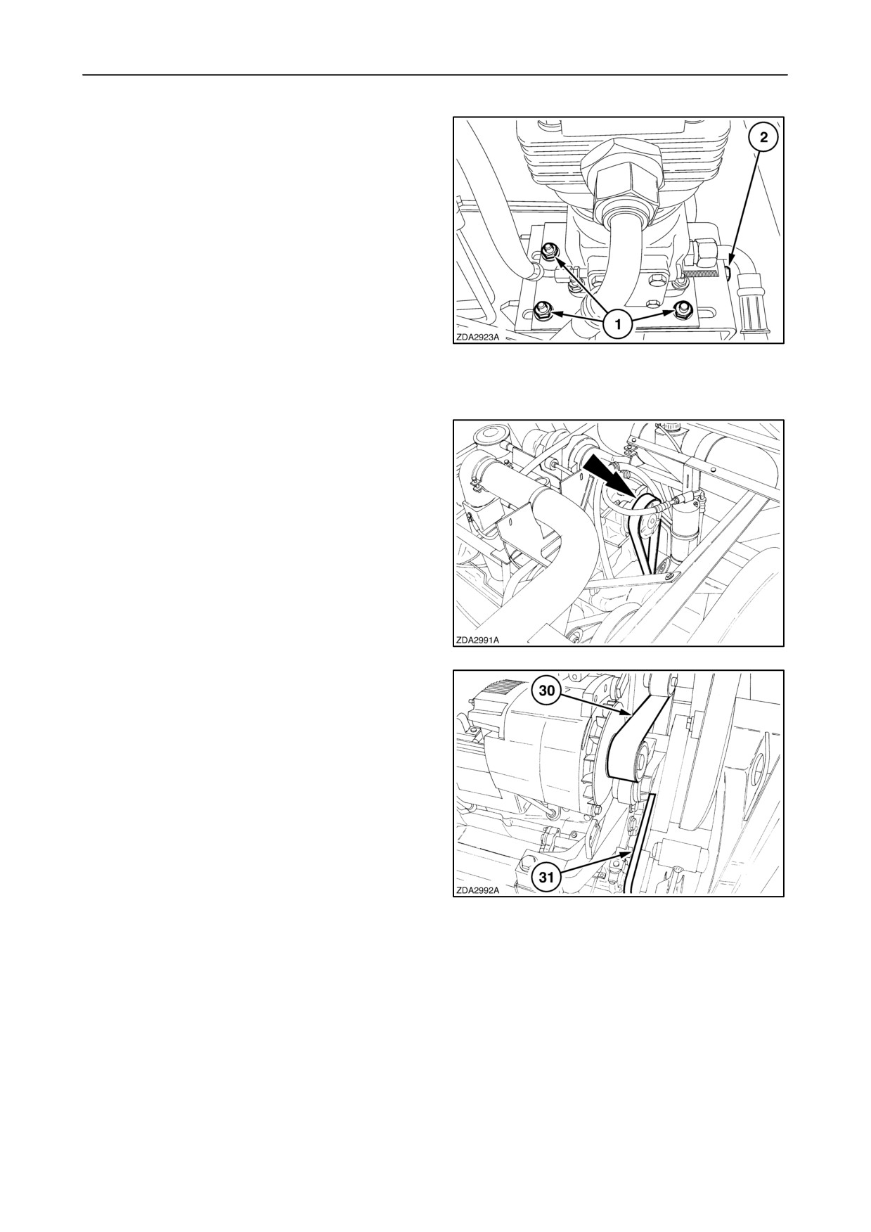
28. Air compressor belt (CNH engine)
The belt tension is correct :
Applying a force of 23 N (5.17 lbf) on the midpoint of
the belt between the two pulleys, should deflect the
belt 3 mm (1/8”).
To adjust the belt tension, proceed as follows:
1. Loosen three nuts 1.
2. Adjust belt tension with bolt 2.
3. Tighten nuts 1.
159
29. Alternator,
waterpump
and
air
conditioning compressor drive belt
(CNH engine)
Self-adjusting idler, no adjustment needed.
160
30. Alternator and waterpump drive belt
(Iveco engine)
Self-adjusting idler, no adjustment needed.
31. Air conditioning compressor drive belt
Self-adjusting idler, no adjustment needed.
161
4-66
SECTION 4 - LUBRICATION AND MAINTENANCE
FEEDING
Straw elevator chain
To adjust the straw elevator chain refer to paragraph
”Belts and Chains” of this section.
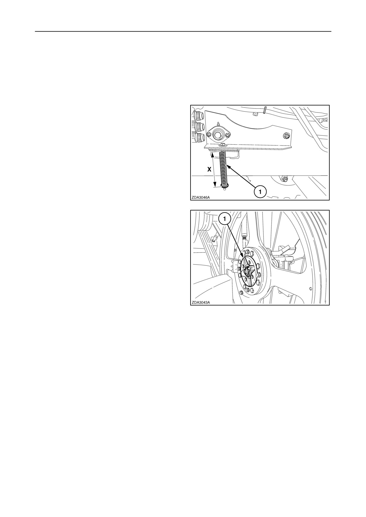
Intermediate roll (if installed)
For correct functioning of the intermediate roll,
springs 1 on both sides should be tensioned to length
“X” = 174 - 176 mm (6 - 7/8” - 6 - 15/16”).
162
Slip clutch
The audible slip clutch 1 is factory-set for average
conditions and may not be further tensioned.
163
4-67
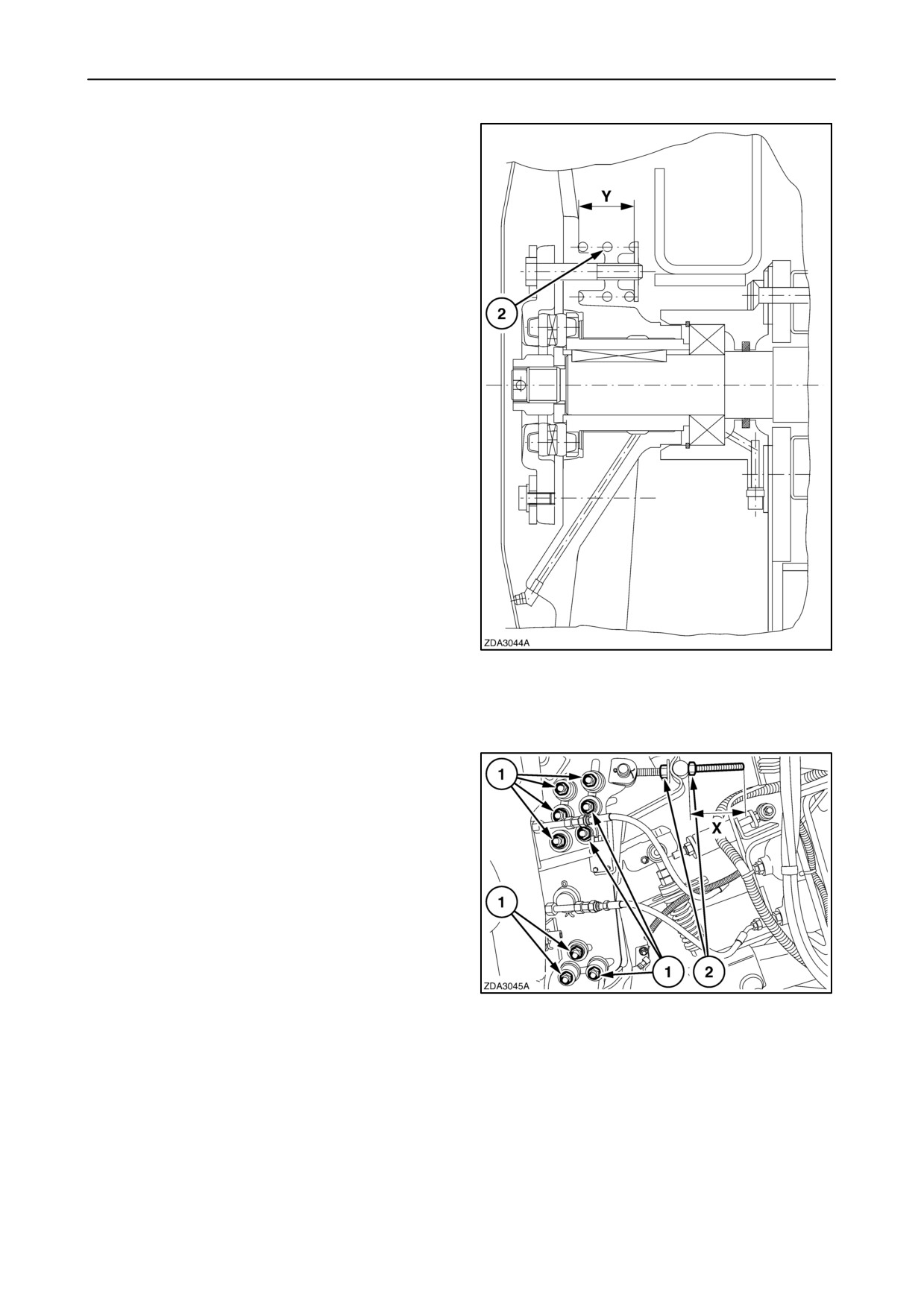
SECTION 4 - LUBRICATION AND MAINTENANCE
Correct clutch tension (in case of disassembly)
The length of springs 2 should measure
“Y” = 37-39 mm (1 - 1/2” ).
The slip clutch torque is +/- 600 Nm (442,6 ft.lbs).
164
Front Face Adjustment (if installed)
The operating angle of the header is adjustable to
improve crop feeding. The angle of the straw elevator
front face can equally be adjusted by changing
distance “X”.
factory-set to 118 - 122 mm (4 - 5/8” - 4 -13/16”).
To adjust the angle of the front face, proceed as
follows on both sides of the machine:
1. Loosen nine nuts 1 on both sides.
2. Adjust the front face angle with nuts 2.
3. Tighten nuts 2.
4. Tighten nuts 1 to a minimum torque of 300 Nm
(221,3 ft.lbs).
165
NOTE: Make sure the straw elevator slats do not
interfere with the dust plates at the front part of the
straw elevator.
4-68
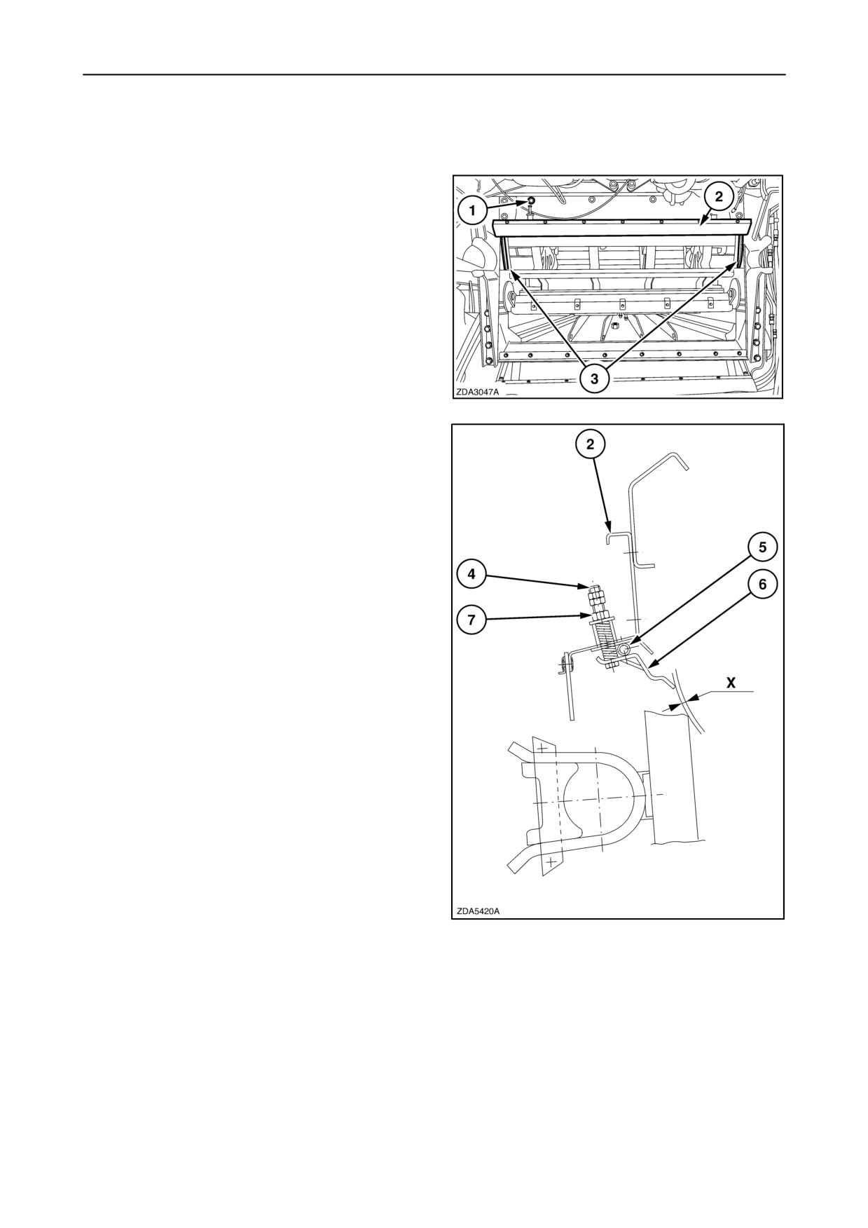
SECTION 4 - LUBRICATION AND MAINTENANCE
THRESHING
Anti-dust plate
Remove the anti-dust plate 2 and antiwrap shields 3
in maize/ sunflowers.
To remove the anti-dust plate, proceed as follows:
1. Unscrew bolts 1 and remove plate 2 to which
anti-dust plate is fitted.
166
2. Unscrew two bolts 4.
3. Pull out rod 5 to remove anti-dust plate 6.
4. Reinstall plate 2.
NOTE: To reinstall the anti-dust plate, proceed in
reverse order of the removal sequence and adjust
nuts 7 until there is a clearance of 1 - 5 mm
(5/128’’ - 3/16’’) between the plate and the nearest
drum rasp bar on nearest position.
167
4-69
SECTION 4 - LUBRICATION AND MAINTENANCE
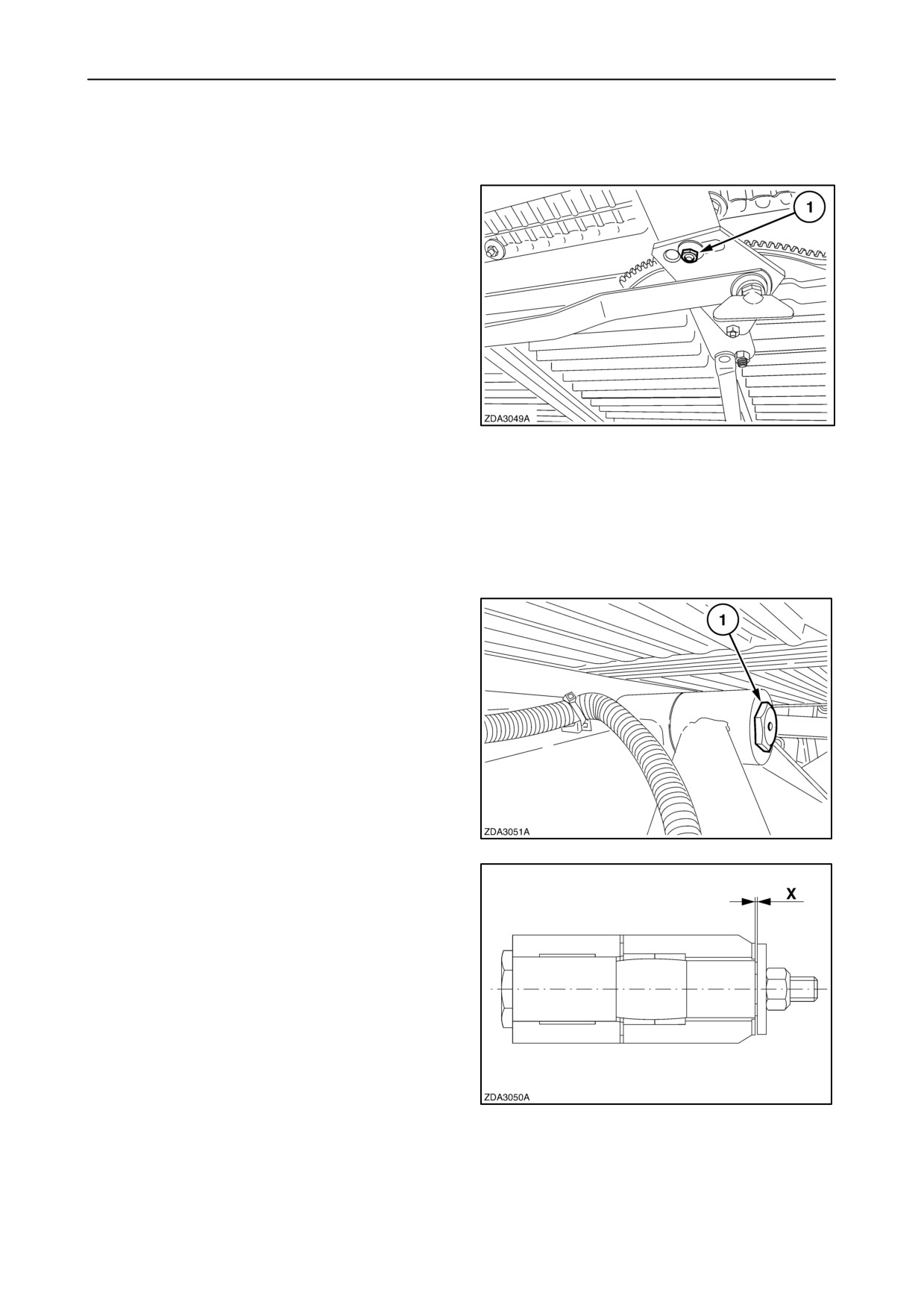
CLEANING
Sieves
On the CX800 models, the upper and lower sieve
consists of two sieve halves.
On both sieves, equipped with remote control, adjust
with bolt 1 on the sieve handle so the left hand and the
right hand part of the sieve have the same opening.
This opening should be measured at 3 mm (1/8”)
opening defined in the direction closed to open.
168
To calibrate the sieves refer to
“SECTION 2 -
CONTROLS, INSTRUMENTS AND OPERATION”;
paragraph: “5.Calibration”,
“Calibration of the upper/lower sieve”.
Pivot axle (self levelling cleaning shoe)
Check annually the axial space on the pivot axle 1
between the frame and the self levelling cleaning
shoe.
169
If there is more space than “X” =0.5 mm (1/64”),
contact your local dealer.
170
4-70
SECTION 4 - LUBRICATION AND MAINTENANCE
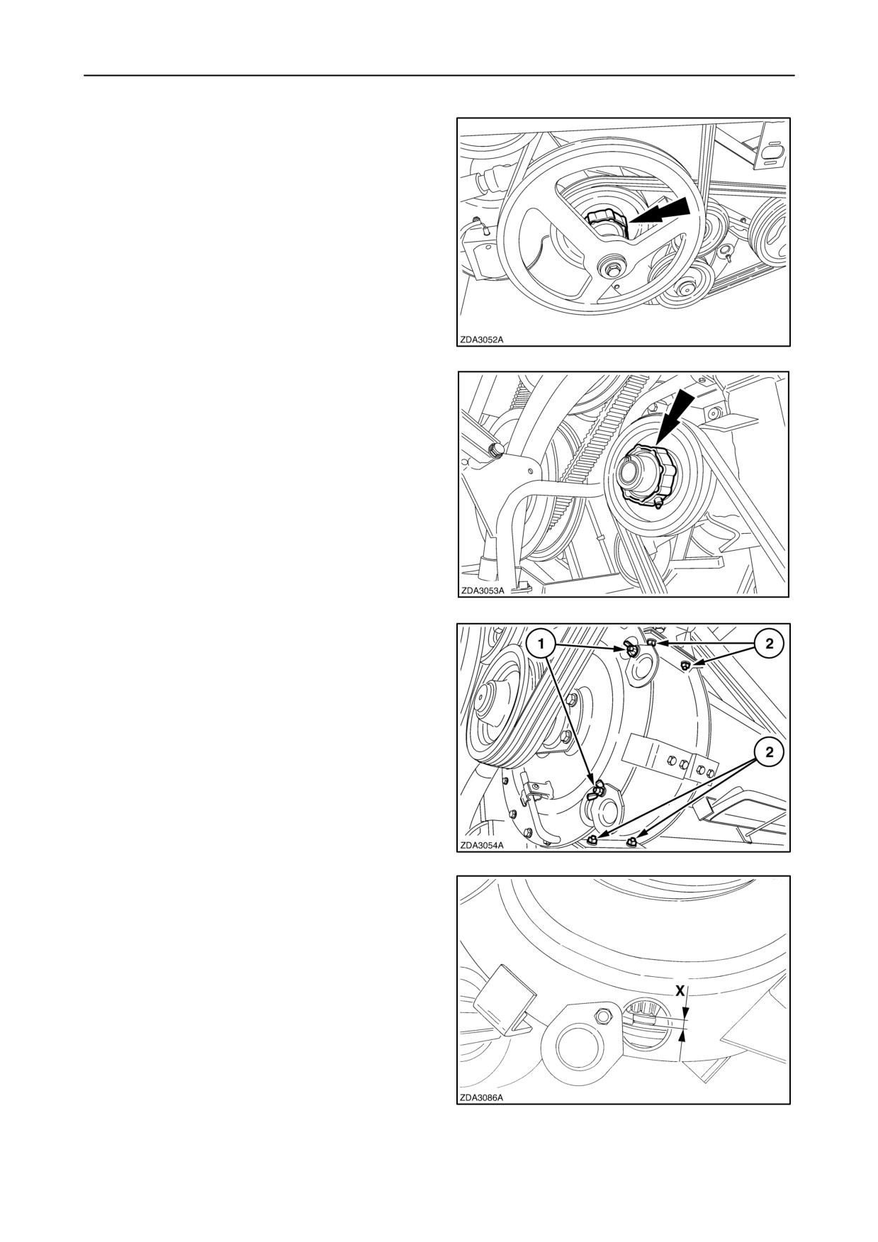
Roto-threshers
SLIP CLUTCH
The audible slip clutch on the roto-thresher shaft
protects the returns drive line.
This slip clutch is factory-set and does not need any
adjustment.
• Slip clutch on the roto-thresher of the self levelling
cleaning shoe models.
171
• Slip clutch on the roto-thresher of the fixed
cleaning shoe models.
172
The roto-thresher concave is adjustable, proceed as
follows:
1. Open covers above the inspection holes 1.
2. Loosen four bolts 2.
173
3. Move the roto-thresher concave to a minimum of
X=5-7 mm (3/16”-1/4”) from the roto-thresher
teeth.
4. Check the adjustments through inspection holes.
If grain crackage is experienced, increase
distance X.
5. Retighten four bolts.
6. Close the covers over the inspection holes.
174
4-71
SECTION 4 - LUBRICATION AND MAINTENANCE
GRAIN STORAGE
Slip clutch
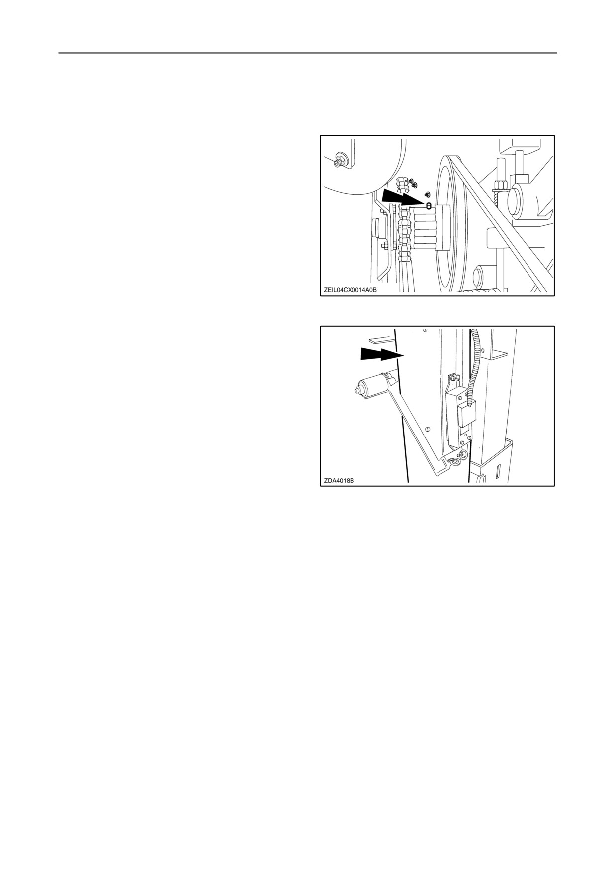
The clean grain drive line is protected by an audible
slip clutch.
This slip clutch is factory-set and does not need any
adjustment.
175
Moisture sensor (if installed)
The moisture sensor measures grain that is falling out
of the clean grain elevator into a small bin of the
bypass unit. The moisture content of the grain in this
bin is sensed by the moisture sensor at the back of
the bypass unit. The level of grain in the bin is
controlled by a proximity switch, which is located at
the top of the bin and an auger at the bottom of the
bin. In order to have a good moisture reading the
moisture sensor fin must always be clean and
covered totally by grain.
In other words the bin has to contain always a
minimum amount of grain.
176
4-72
SECTION 4 - LUBRICATION AND MAINTENANCE
• The moisture sensor fin must be clean.
A sensor fin covered with dirt and crop residue will
result in wrong moisture readings.
Therefore it is advised to clean the sensor fin when
necessary. The frequency of the cleaning is
dependent on the harvesting conditions.
Certainly in case of dirty, and conditions where other
parts of the combine tend to build up dirt (grain pan,
sieves, bubble-up auger) it is advised to check the
sensor fin daily and clean it if necessary.
To clean the sensor fin proceed as follows:
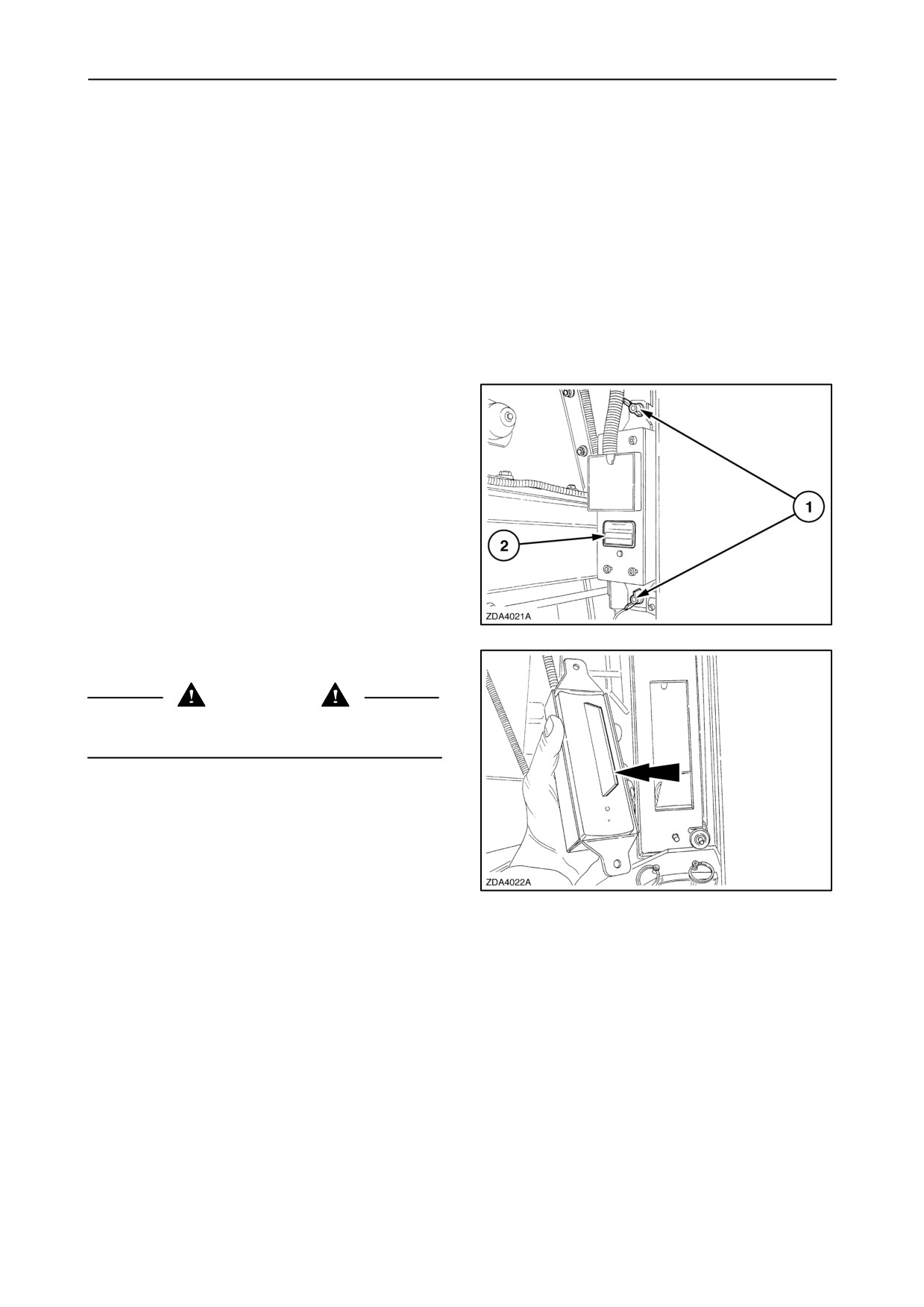
1. Loosen two wing nuts 1 to remove sensor fin 2.
177
2. Clean the fin, using a clod.
CAUTION
Do not use a screwdriver or any other sharp device
to avoid scratches on the sensor fin to clean.
3. Install the sensor fin and tighten the wing
nuts.(fig. 177)
4. To calibrate the moisture sensor, refer to
“SECTION 2 - CONTROLS, INSTRUMENTS
AND OPERATION”.
178
4-73
SECTION 4 - LUBRICATION AND MAINTENANCE
• The level sensor must be clean.
(proximity switch)
NOTE: It should be remarked that due material
blockage (pieces of maize cobs) in front of the level
sensor will also cause the auger to turn continuously
when the threshing is on. This situation can be
recognized when the moisture readings are
abnormally low or largely fluctuating. Therefore
remove the moisture sensor. Then you can look into
the bin. In the top of the bin a white circle (=level
sensor head surface) must be visible without being
covered by dirt or crop residues. If you found material
accumulated in front of the level sensor, remove it.
To check if the level sensor (proximity switch) is
clean, proceed as follows:
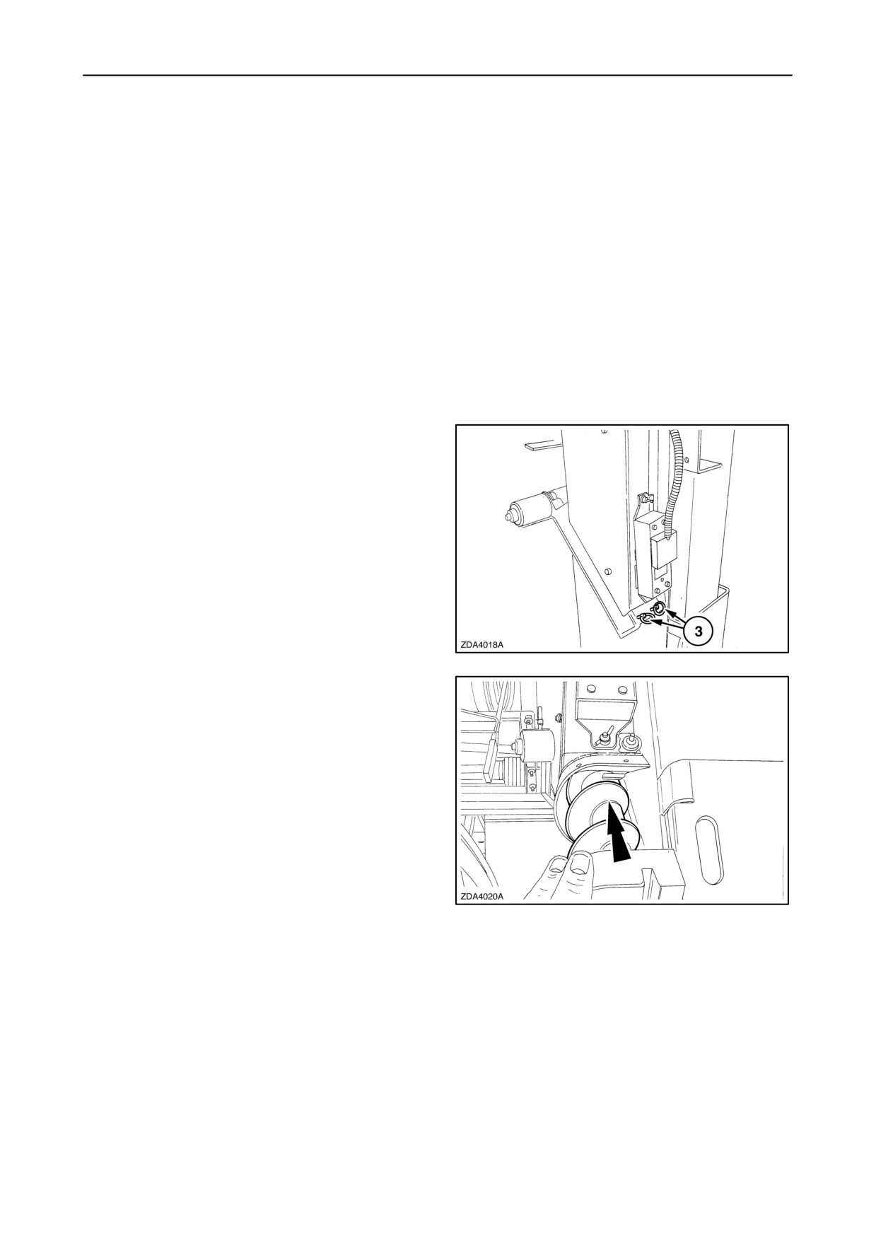
1. Pull two pins 3 out to remove the auger.
179
2. Remove the auger.
180
4-74
SECTION 4 - LUBRICATION AND MAINTENANCE
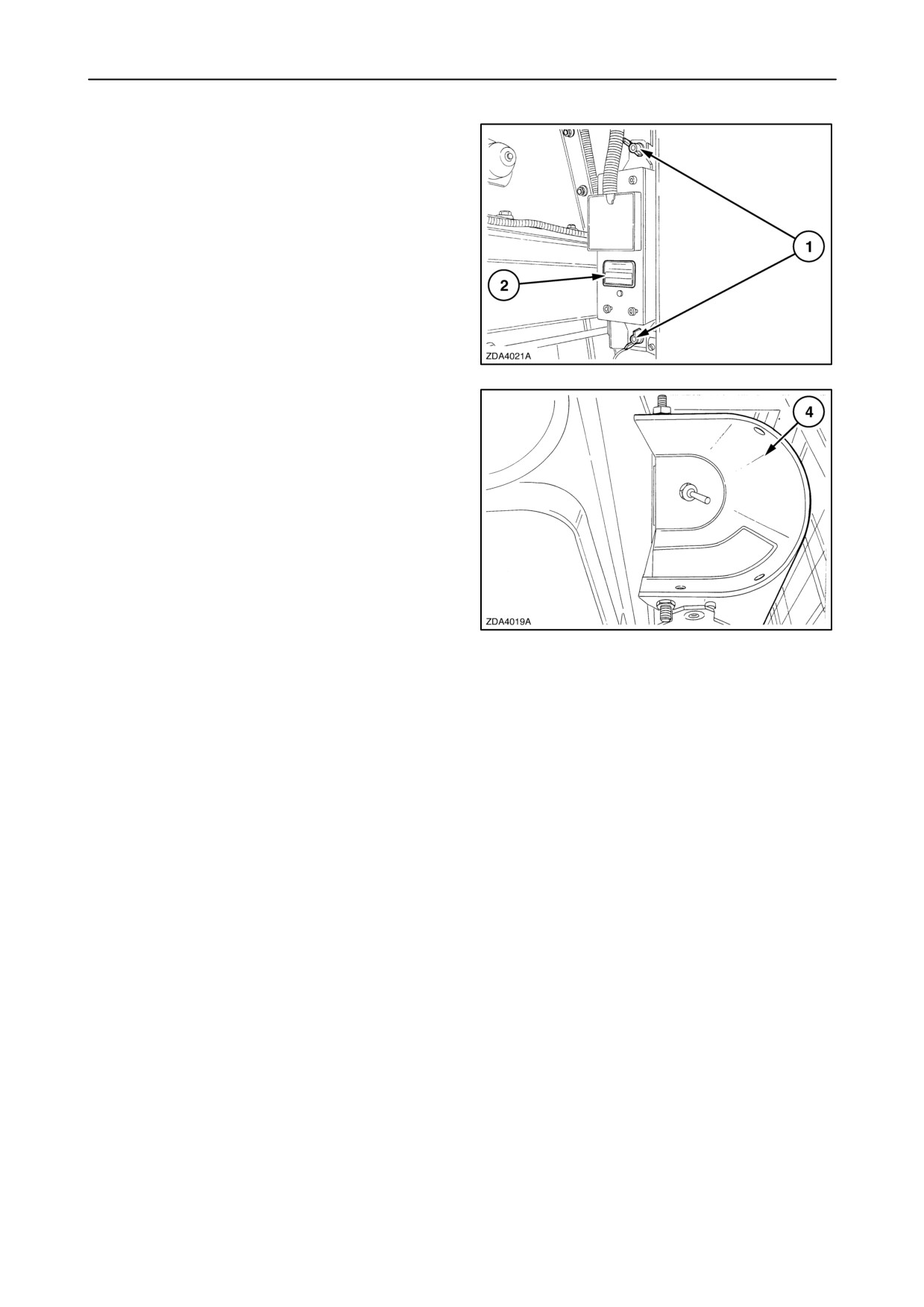
3. Loosen two wing nuts 1 to remove sensor fin 2.
181
4. Remove all the grain out of auger chamber 4.
NOTE: No grain may be in front of the level sensor.
5. If there is still grain or dirt in front of the level
sensor, remove it.
182
6. Install the auger and install the two pins.
7. Install the sensor fin and tighten the wing nuts.
NOTE: If the moisture reading is still fluctuating or the
electrical motor keeps on turning all the time when
threshing is on then contact your local dealer.
4-75
SECTION 4 - LUBRICATION AND MAINTENANCE
Grain flow sensor (if installed)
There are two important points to have a good
functionality of the grain flow sensor:
• The sensor plate must be clean
In some harvesting conditions it can happen that
material starts building up on the sensor plate. These
conditions can be recognised when other combine
elements (sieves, bubble-up auger, grain pan) start to
accumulate dirt. In case of serious material built up,
the readings of the sensor will become wrong.
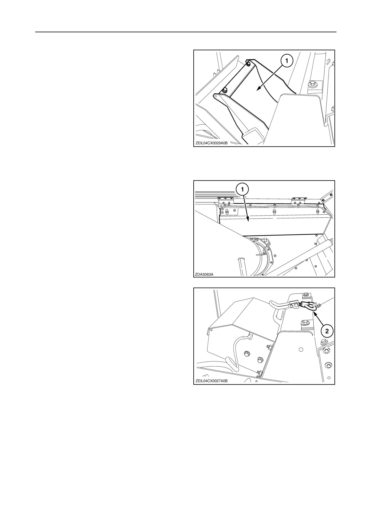
Therefore it is advised to check daily. Clean sensor
plate 1 whenever other combine elements in the
183
combine needs to be cleaned for proper functioning.
To clean, proceed as follows:
1. Open the grain tank covers (if installed)
2. Remove the cover 1.
184
3. Open fast coupler 2 on top of the grain elevator
and swing the sensor open to the front of the
combine.
185
4-76
SECTION 4 - LUBRICATION AND MAINTENANCE
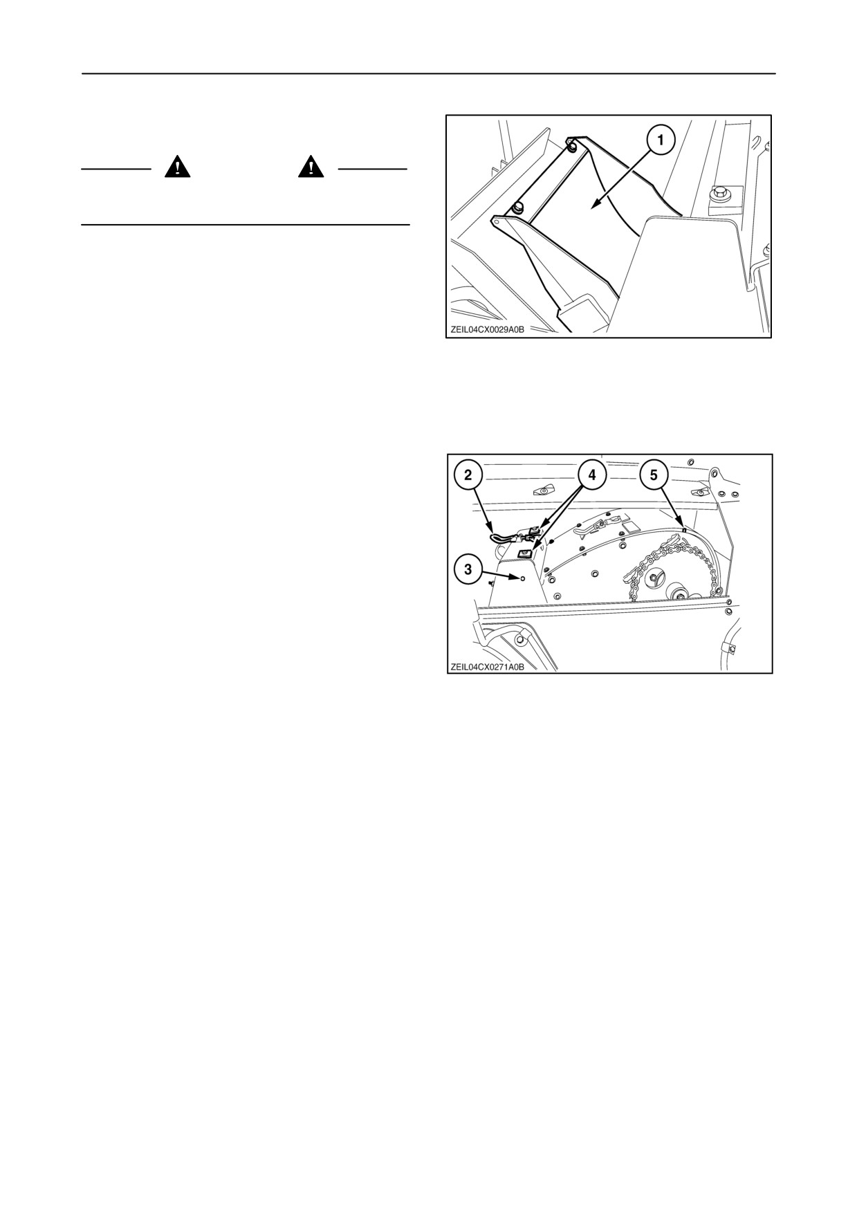
4. Sensor plate 1 is now visible and can be cleaned
if necessary.
CAUTION
Do not use a screwdriver or any other sharp device
to avoid scratches on the sensor plate.
5. Close the sensor and secure with the fast coupler.
6. Reinstall the cover.
To calibrate the grain flow sensor, refer to
“SECTION 2 - “CONTROLS, INSTRUMENTS AND
OPERATION”.
186
To adjust the sensor plate 1 (fig. 186), proceed as
follows:
1. The sensor plate 1 is adjusted correctly, if it is
possible to insert a rod into hole 3.
2. If not, adjust the plate by adjusting the two
supports 4 in combination with the fast coupler 2.
187
4-77