New Holland T6010, T6020, T6030, T6050, T6070 Delta and Plus Tractors. Operator's Manual - page 9
SECTION 4 -- LUBRICATION AND MAINTENANCE
EVERY
1200
HOURS OR 2 YEARS
(whichever occurs first) carry out the
preceding checks plus the following:
OPERATION 30
COOLING SYSTEM
During manufacture, the engine cooling system is
filled with a high quality antifreeze and water solution.
The antifreeze contains a chemical inhibitor. This
inhibitor increases and extends the protection
offered by conventional antifreezes.
The inhibitor will:
• Increase rust prevention.
• Reduce scale formation.
• Minimise cylinder wall erosion (pitting).
• Reduce foaming of the coolant.
The chemical inhibitor must be replenished, at
intervals, to maintain the optimum protection level.
This protection is provided by draining and flushing
the system and refilling with a 50% solution of
ethylene glycol antifreeze or, where a suitable type
of antifreeze is not available, with a measured
dosage of chemical inhibitor. See the following text.
See page 4--9 for Antifreeze specification.
Draining and Refilling the Cooling System
WARNING
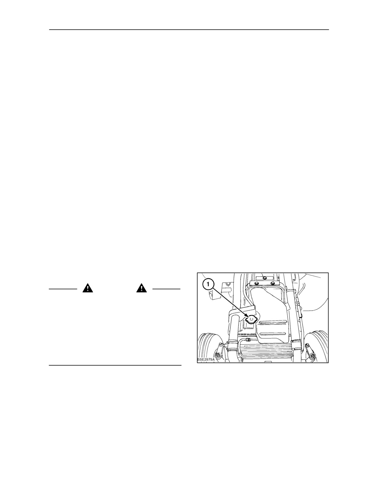
Allow the engine to cool before draining the coolant.
The cooling system operates under pressure which
is controlled by the radiator pressure cap. It is
dangerous to remove the pressure cap while the
system is hot. When cool, use a thick cloth and turn
the cap slowly to the first stop and allow the pressure
to escape before fully removing the cap. Coolant
should be kept off the skin. Adhere to the precautions
outlined on the antifreeze and inhibitor containers,
where used.
92
IMPORTANT: It is essential that an approved
pressure cap is used. If the cap is mislaid or
damaged, obtain a replacement from your dealer.
4--43
SECTION 4 -- LUBRICATION AND MAINTENANCE
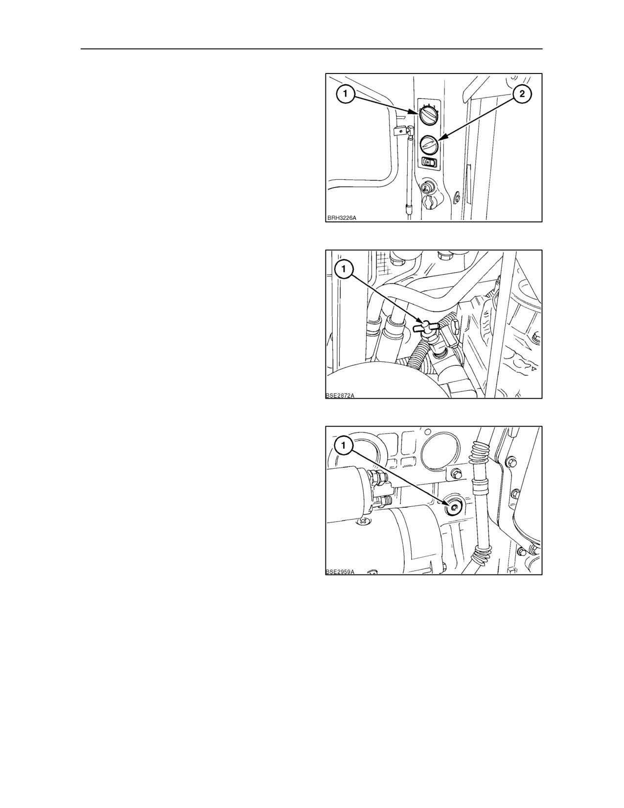
1. Turn the heater control knob (2) to the maximum
heat position (fully clockwise).
93
2. Check that the heater shutoff valve is open. This
valve is on the rear, right hand side of the engine
cylinder head.
3. Disconnect the radiator lower hose and drain all
the coolant into a suitable container. Dispose of
the coolant properly.
94
4. Remove the coolant drain plug (1) from the left
hand rear of the engine block. Drain all the
coolant into a suitable container. Dispose of the
coolant properly.
5. To increase the drainage rate, remove the
radiator cap and recovery tank cap.
6. Flush the system with a commercial cooling
system cleaner. Follow the instructions supplied
with the cleaner. Drain the cleaner and let the
engine cool.
IMPORTANT: Never put cold coolant in a hot
engine. The difference in temperature could cause
95
the the block or head to crack.
4--44
SECTION 4 -- LUBRICATION AND MAINTENANCE
7. Re--install the radiator lower hose.
Using Plain water
8. Fill the system with clean water and run the
If you reside in a country where antifreeze is not
engine for 10 minutes, then drain all the water.
available, use clean water pre--mixed with
5%
Allow the engine to cool.
chemical inhibitor. Contact your authorised dealer.
9. Fill the system with a blend of antifreeze and
Following the instructions on the container mix the
clean soft water. Add coolant slowly through the
recommended quantity of inhibitor with 28.5 litres
radiator filler neck until the coolant reaches the
(7.5 U.S. gal.) of clean water. This will provide more
bottom of the filler neck.
coolant mixture than is actually required. The excess
coolant should be kept in a specially marked
NOTE: To avoid trapping air in the system, fill the
container and used for top up purposes.
radiator as slowly as possible thereby allowing any
air pockets to disperse.
WARNING
Inhibitor solution is irritating to eyes and skin . It
The coolant to be used is dependent upon local
contains buffered potassium hydroxide.
availability. See the folling text:
• Avoid contact with eyes or prolonged or
Using Antifreeze
repeated skin contact.
Use a solution of
50% clean water and 50%
• Wear protective eyewear when using .
antifreeze. The inhibitor already in this antifreeze is
• In case of contact with eyes, flush with water for
sufficient to protect your engine for a further 1200
15 minutes and obtain medical attention.
hours or two years, whichever occurs first.
• Wash skin with soap and water after use.
See page 4--9 for Antifreeze specification.
• Keep out of reach of children.
4--45
SECTION 4 -- LUBRICATION AND MAINTENANCE
After Refilling the System
-- All Coolant
Solutions
1. Inspect cooling system hoses and connections
for leaks.
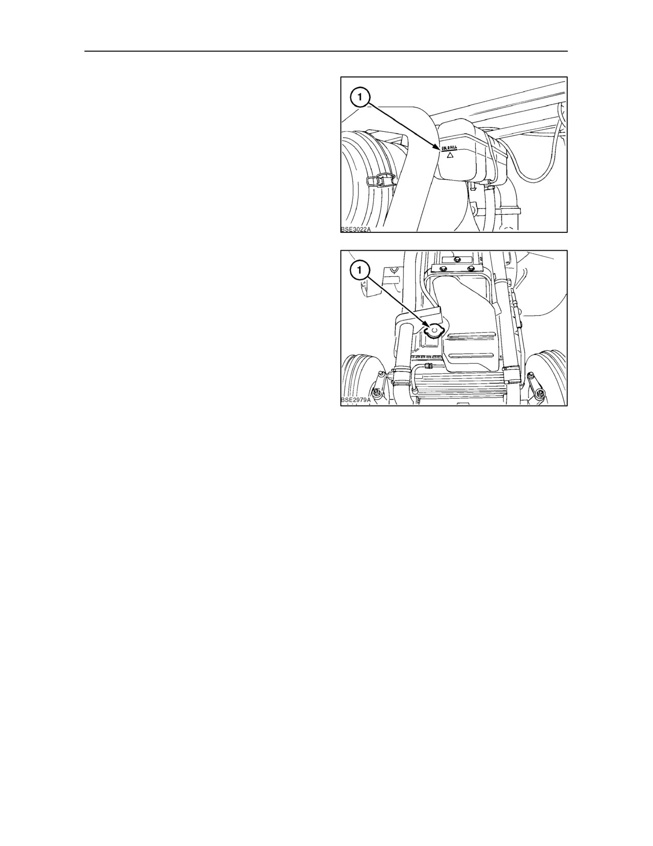
2. Fill the coolant recovery tank to the cold fill mark
(1).
3. Start the engine and run it until normal operating
temperature is reached.
NOTE: The coolant level will drop as coolant is
pumped around the system.
96
4. Stop the engine and allow the coolant to cool.
5. Remove the radiatior cap (1), and add coolant to
the radiator to bring the coolant level to the
bottom of the filler neck. Install the radiator cap.
Add coolant to the recovery tank as required to
bring the level up to the cold mark.
NOTE: If the engine is not going to be operated
immediately following this coolant change, run the
engine for one hour to ensure that the antifreeze
and/or chemical inhibitor is dispersed throughout the
cooling system. Allow the engine to cool and make
a final check to ensure that the coolant level is
97
satisfactory.
Coolant Capacities
Antifreeze Specification:
See page 4--9 for Antifreeze specification.
Tractors with 4 cylinder engines:
With Cab
23.0 litres
(6.07 U.S. gals)
Less Cab
21.0 litres
Chemical Inhibitor
(5.54 U.S. gals)
There are three part numbers for the inhibitor. The
Tractors with 6 cylinder engines:
content of each bottle is identical, only
the
With Cab
25.0 litres
instructions on the label differ,by language:
(6.6 U.S. gals)
Less Cab (except T6070)
23.0 litres
Part No.
Languages on Label
(6.07 U.S. gals)
83958743
English, French, Spanish,
Portuguese and Greek
Clean Water Specification:
83958744
English, French, German,
Total Hardness
300 parts per million
Italian and Dutch
Chlorides
100 parts per million
83958745
English, Danish, Norwegian,
Sulphates
100 parts per million
Finnish and Swedish
4--46
SECTION 4 -- LUBRICATION AND MAINTENANCE
OPERATION 31
CHANGE ENGINE AIR CLEANER
INNER ELEMENT
The air cleaner is accessible from the right--hand
side of the engine
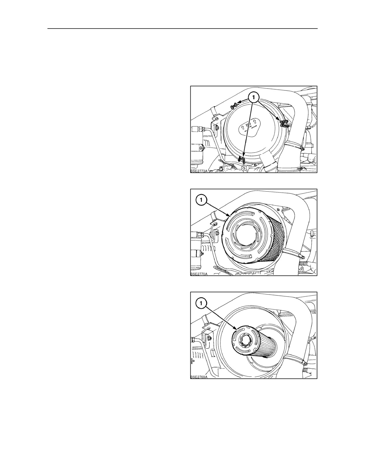
1. Unlatch the three retaining clips (1) Fig. 98, and
lift off the air cleaner assembly cover.
98
2. Remove the outer element (1) Fig. 99 from the
air cleaner assembly by gently twisting the end
of the filter clockwise to disengage the seal. Then
pull the filter straight out of the housing ,not at an
angle, ensuring the inner element remains in
place.
NOTE: Examine the inside of the outer element. If
dust is present, the outer element is defective and
must be replaced.
99
3. Pull the inner element straight out of the housing
and dispose of properly.
4. Clean the inside of the air cleaner housing using
a damp lint--free cloth.
5. Install a new inner element and a new outer
element (if required). Ensure both elements are
correctly seated before replacing the housing
cover.
IMPORTANT: Failure to install the inner filter
element properly could result in engine damage.
Therefore it is recommended that the element be
installed by an authorised dealer.
100
4--47
SECTION 4 -- LUBRICATION AND MAINTENANCE
OPERATION 32
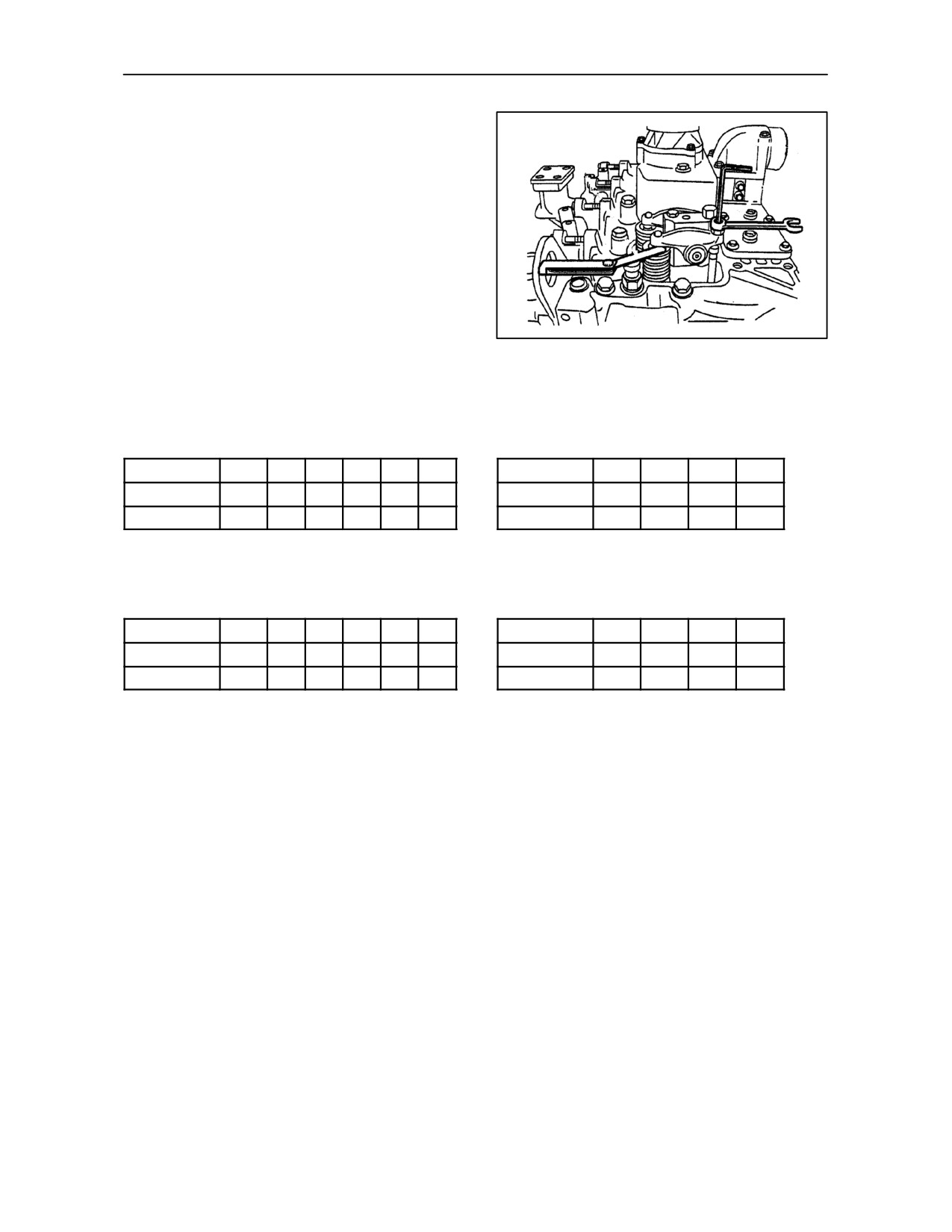
CHECK VALVE TAPPET CLEARANCE
With the engine cold, ease the ventilation tube from
the valve rocker cover after removing the retaining
bolt. Undo the retaining nuts and remove the valve
cover.
The correct valve clearance for all models are:
Inlet
0.25+/-- 0.05mm (0.010+/-- 0.002in.)
Exhaust
0.51+/-- 0.05mm (0.020+/-- 0.002in.)
101
Check the valve clearance for 6 cylinder engines as
Check the valve clearance for 4 cylinder engines as
follows:
follows:
Cylinder No.
1
2
3
4
5
6
Cylinder No.
1
2
3
4
Intake
--
--
--
Intake
--
Exhaust
--
--
--
Exhaust
--
--
--
Rotate the crankshaft and balance No. 1 cylinder
Rotate the crankshaft and balance No.1 cylinder
valves. Adjust the valves marked by the asterisk (*)
valves. Adjust the valves marked by the asterisk (*)
as shown in the table above:
as shown in the table above:
Cylinder No.
1
2
3
4
5
6
Cylinder No.
1
2
3
4
Intake
--
--
--
Intake
--
--
--
Exhaust
--
--
--
Exhaust
*
--
Rotate the crankshaft and balance No.6 cylinder
Rotate the crankshaft and balance No.4 cylinder
valves. Adjust the valves marked by the asterisk (*)
valves. Adjust the valves marked by the asterisk (*)
as shown in the table above:
as shown in the table above:
4--48
SECTION 4 -- LUBRICATION AND MAINTENANCE
OPERATION 33
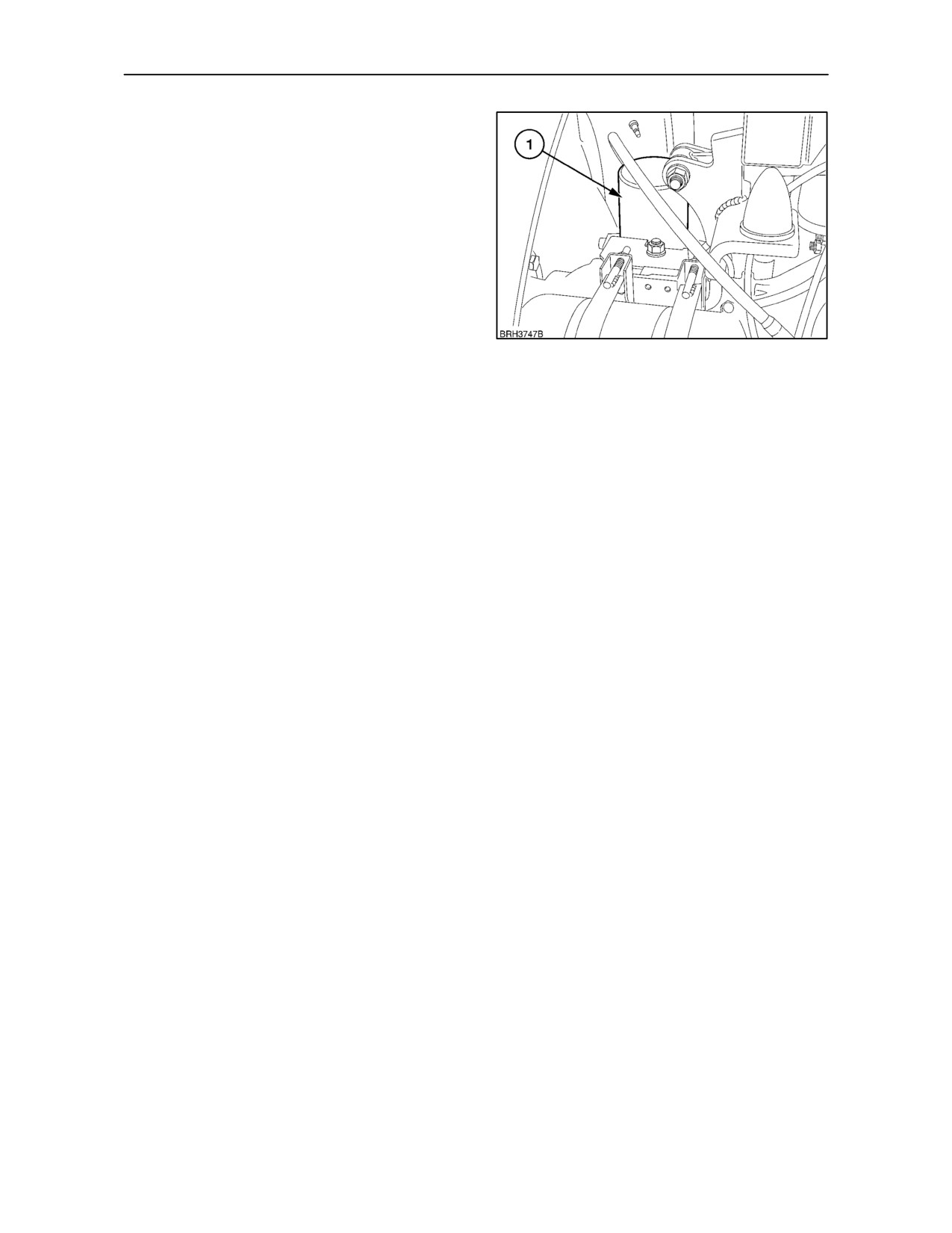
CHANGE AIR BRAKE DRIER RESERVOIR
Removing the Drier Reservoir
Before attempting to change the drier reservoir (1),
thoroughly clean the area around the reservoir to
prevent debris from entering the air braking system.
1. Exhaust all air pressure in the system by opening
the drain tap on the main air tank/s.
2. Using a filter release tool, unscrew and remove
the drier reservoir. Dispose of properly according
102
to local regulations.
Installing a New Drier Reservoir
1. Clean the seal flange on the drier body and the
threaded pin, check for damage to the pin and
the seal contact surface of the flange.
2. Lightly grease the sealing ring on the reservoir
and the threaded pin on the drier body.
3. Screw the reservoir onto the drier body until the
seal touches the contact surface of the flange.
Tighten a further half--turn by hand. Tighten to a
maximum of 15 Nm (11 lbf. ft.) DO NOT
overtighten.
4. Pressurise the reservoir and check for leaks. If
further tightening is necessary, depressurise the
system before tightening.
5. Re--pressurise the air braking system and check
again for leaks.
4--49
SECTION 4 -- LUBRICATION AND MAINTENANCE
EVERY 1800
HOURS carry out the
following:
OPERATION 34
CLEAN AND RESET FUEL INJECTORS
WARNING
Diesel fuel escaping under pressure can penetrate
the skin causing serious injury.
Do not use your hand to check for leaks. Use a piece
of cardboard or paper to search for leaks. Wear
protective gloves and eye protection.
103
If any fluid is injected into the skin, obtain medical
attention immeadiately or gangrene may result.
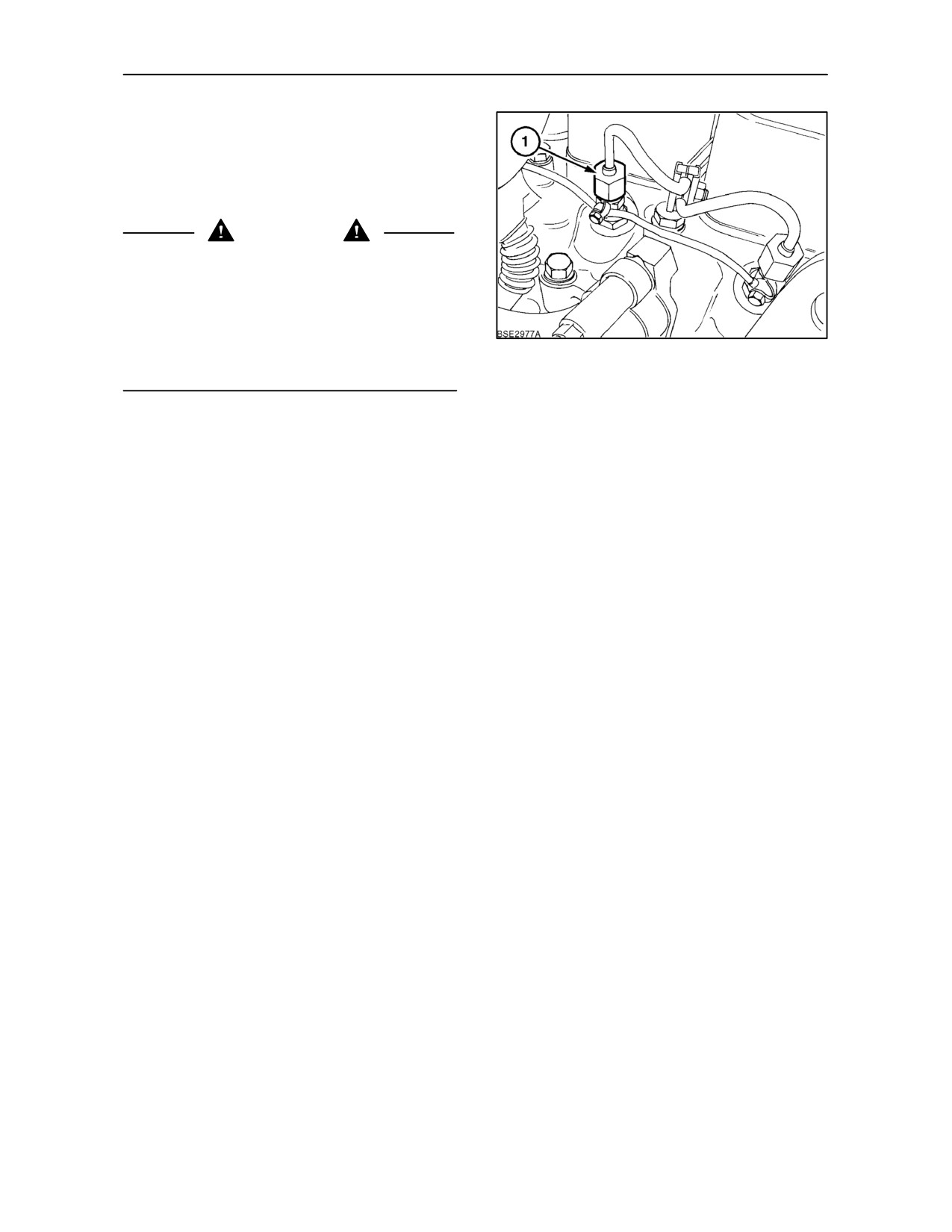
The removal of the fuel injectors (1) for servicing
requires the use of special tools to extract the
injectors from the cylinder head. It is therefore
recommended that your authorised dealer should
carry out this procedure.
4--50
SECTION 4 -- LUBRICATION AND MAINTENANCE
EVERY 3 YEARS carry out the following:
OPERATION 35
SERVICE THE AIR CONDITIONER
SYSTEM
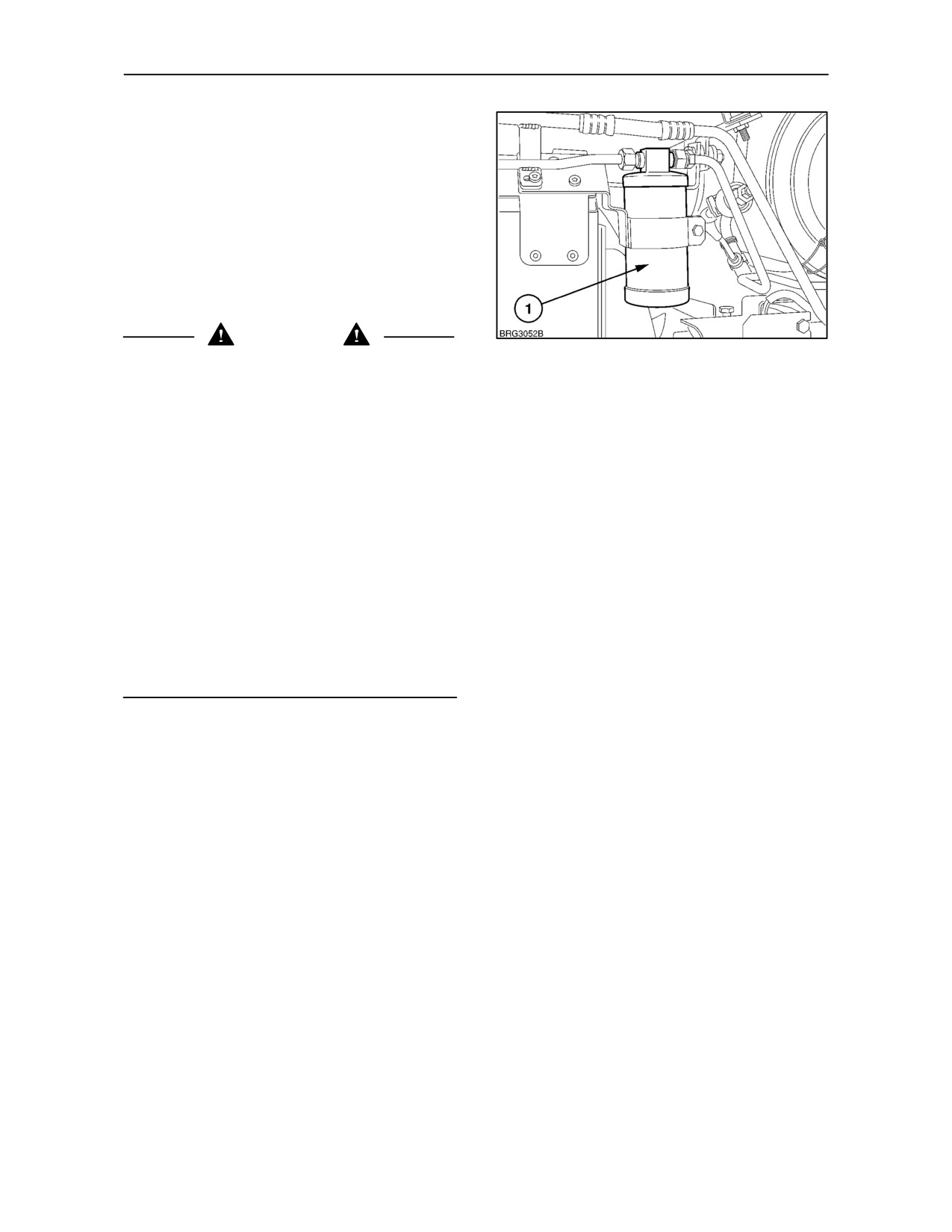
After 3 seasons work, the performance of the air
conditioner may be reduced. At this time it is
recommended to have the receiver/drier (1) changed
and the complete system checked by your
authorised dealer using specialised equipment.
WARNING
104
The refrigerant used in the air conditioner system
has a boiling point of --12 ° C (10 ° F).
• Never expose any part of the air conditioner
system to a direct flame or excessive heat
because of the risk of fire or explosion.
• Never disconnect or disassemble any part of the
air conditioner system. escaping refrigerant will
cause frostbite. Allowing refrigerant to escape
into the atmosphere is illegal in many countries.
• If refrigerant should contact the skin, use the
same treatment as for frostbite. Warm the area
with your hand or lukewarm water at 32 -- 38 ° C
(90 --100 ° F). Cover the area loosely with a
bandage to protect the affected area and to
prevent infection. Consult a doctor immediately.
• If refrigerant should contact the eyes, wash the
eyes immediately with cold water for at least 5
minutes. consult a doctor immediately.
4--51
SECTION 4 -- LUBRICATION AND MAINTENANCE
GENERAL MAINTENANCE (to be
performed as and when required).
OPERATION 36
BLEEDING THE FUEL INJECTION SYSTEM
It may be necessary after injection pump removal,
replacement of injector high pressure lines or after
running out of fuel, to purge the system of air to allow
the engine to start.
If theenginefailstostart after severalturns, afterone
of the above situations has occurred, bleed the
105
system using the following procedure:
1. Ensure the tractor has adequate fuel and the
battery is fully charged.
2. Bleed the fuel system as described in Operation
26.
3.
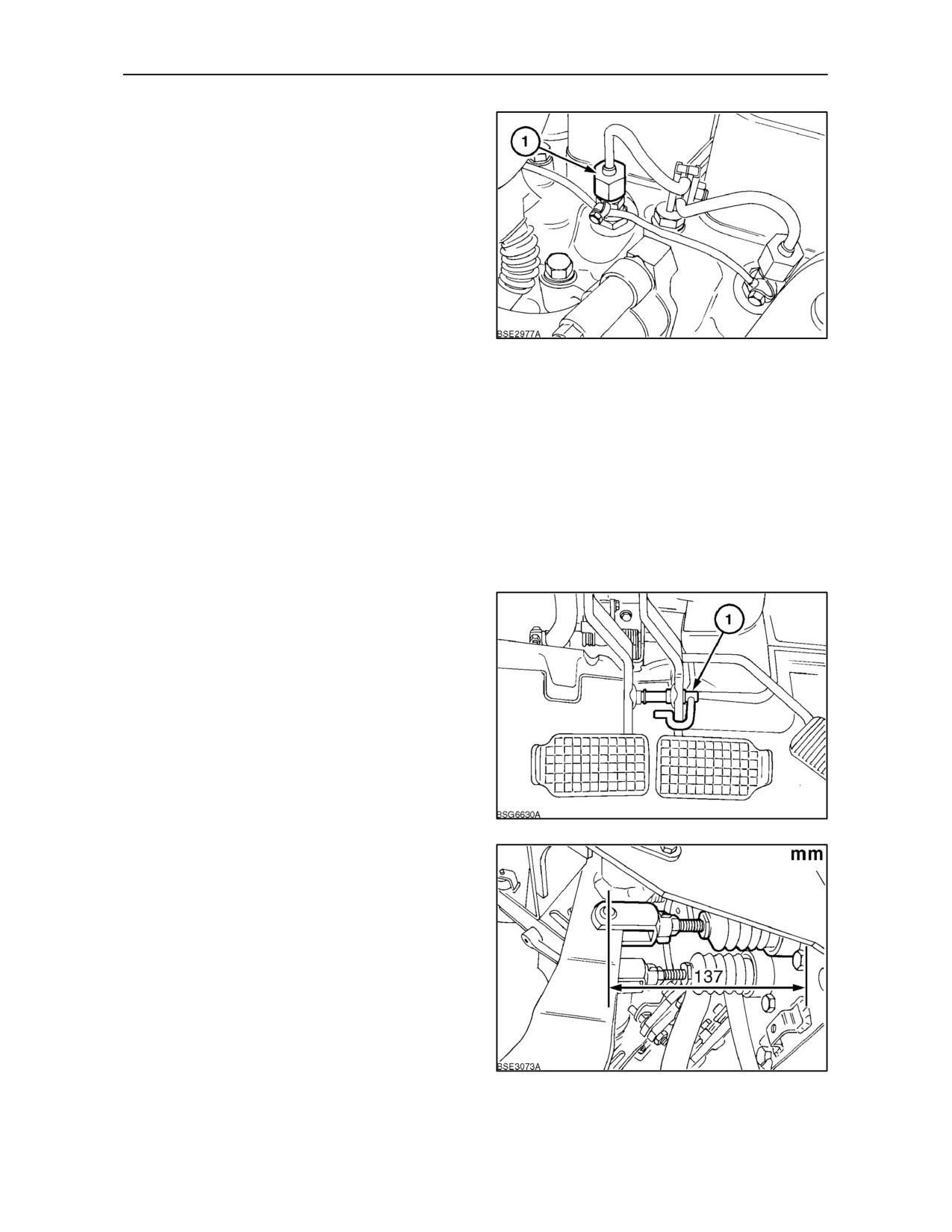
‘Crack’ open the nuts (1) on the high pressure
lines to each of the injectors. With the aid of an
assistant, crank the engine on the starter motor
to expel the air. Tighten the injector nuts as the
engine begins to fire.
OPERATION 37
CHECK BRAKE PEDAL
LATCHING/UNLATCHING
The hydraulically actuated brakes require no
adjustment. However, if any part of the brake pedal
linkage or the master cylinder assembly is replaced
or if the pedal latch will not readily engage the hole
in the right--hand pedal shank, adjust the pedal as
follows:
106
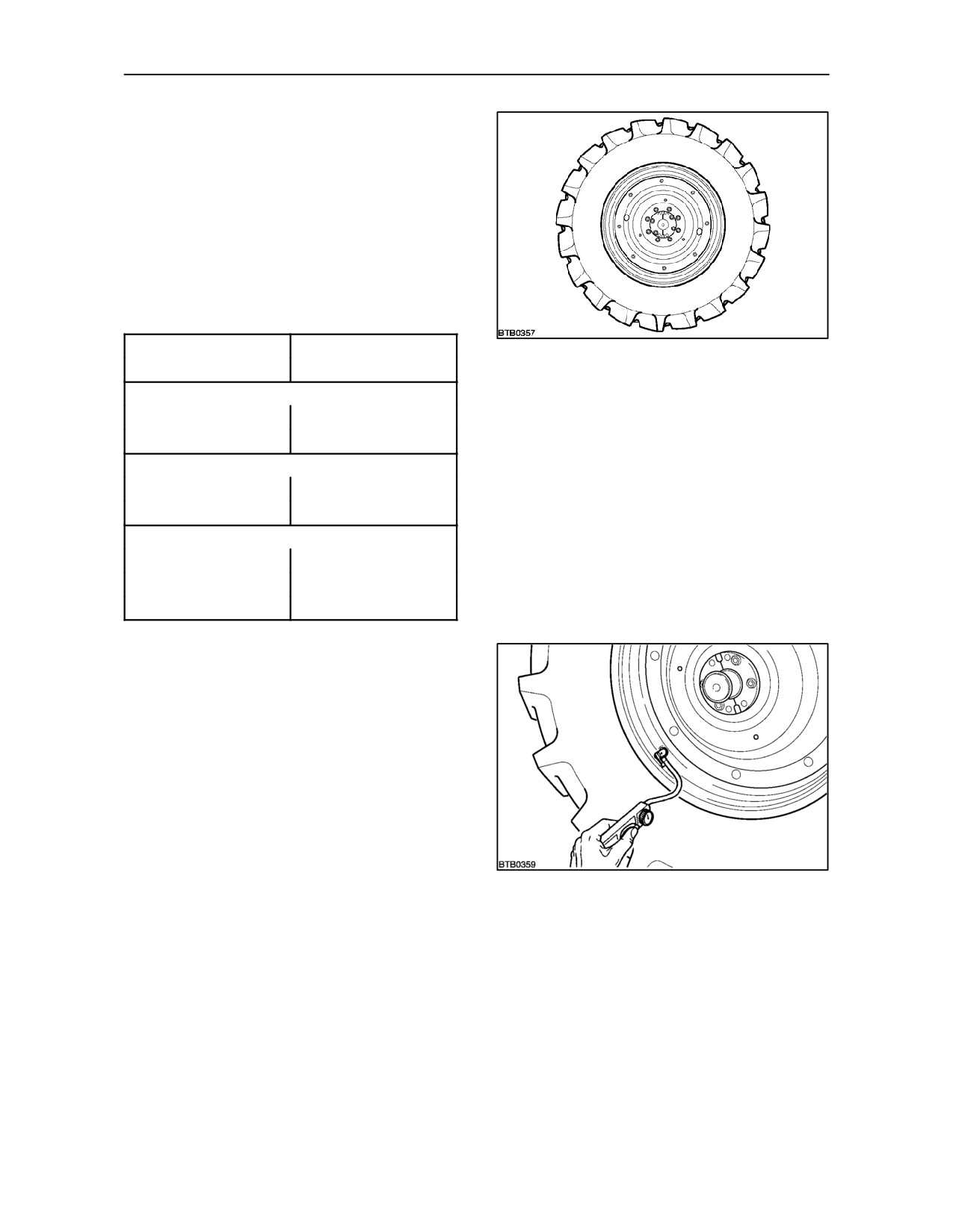
Adjust the clevis by loosening the locknut . The
distance from the bulkhead to the centre of the clevis
hole should be 137mm (5.4 in.). Adjust both pedals
and ensure pedal latch engages properly.
107
4--52
SECTION 4 -- LUBRICATION AND MAINTENANCE
OPERATION 38
CHECK FRONT AND REAR WHEEL NUTS
Check the front and rear wheel nuts for tightness
using a torque wrench (with a torque multiplier,
where necessary).
The specified torque figures are shown in
the
following table:
Wheel Nut Torque Settings
Two wheel drive --
108
Front disc to hub nuts
133 Nm (98 lbf.ft)
Four wheel drive -- Adjustable front wheels
Front disc to hub nuts
294 Nm (217 lbf.ft)
Front disc to rim nuts
250 Nm (184 lbf.ft)
Adjustable rear wheels -- Flanged axle
Disc to hub nuts
250 Nm (184 lbf.ft)
Disc to rim nuts
250 Nm (184 lbf.ft)
Bar Axle
Disc to hub nuts
260 Nm (190 lbf.ft)
Disc to rim nuts
250 Nm (184 lbf.ft)
Split wedge bolts
300 Nm (221 lbf.ft)
OPERATION 39
CHECK TYRE PRESSURES AND TYRE
CONDITION
Check and adjust the front and rear tyre pressures.
Inspect the tread and sidewalls for damage.
Adjust the tyre pressures to suit the load being
carried. See
‘Tyre Pressures and Permissable
Loads’ in Section 3.
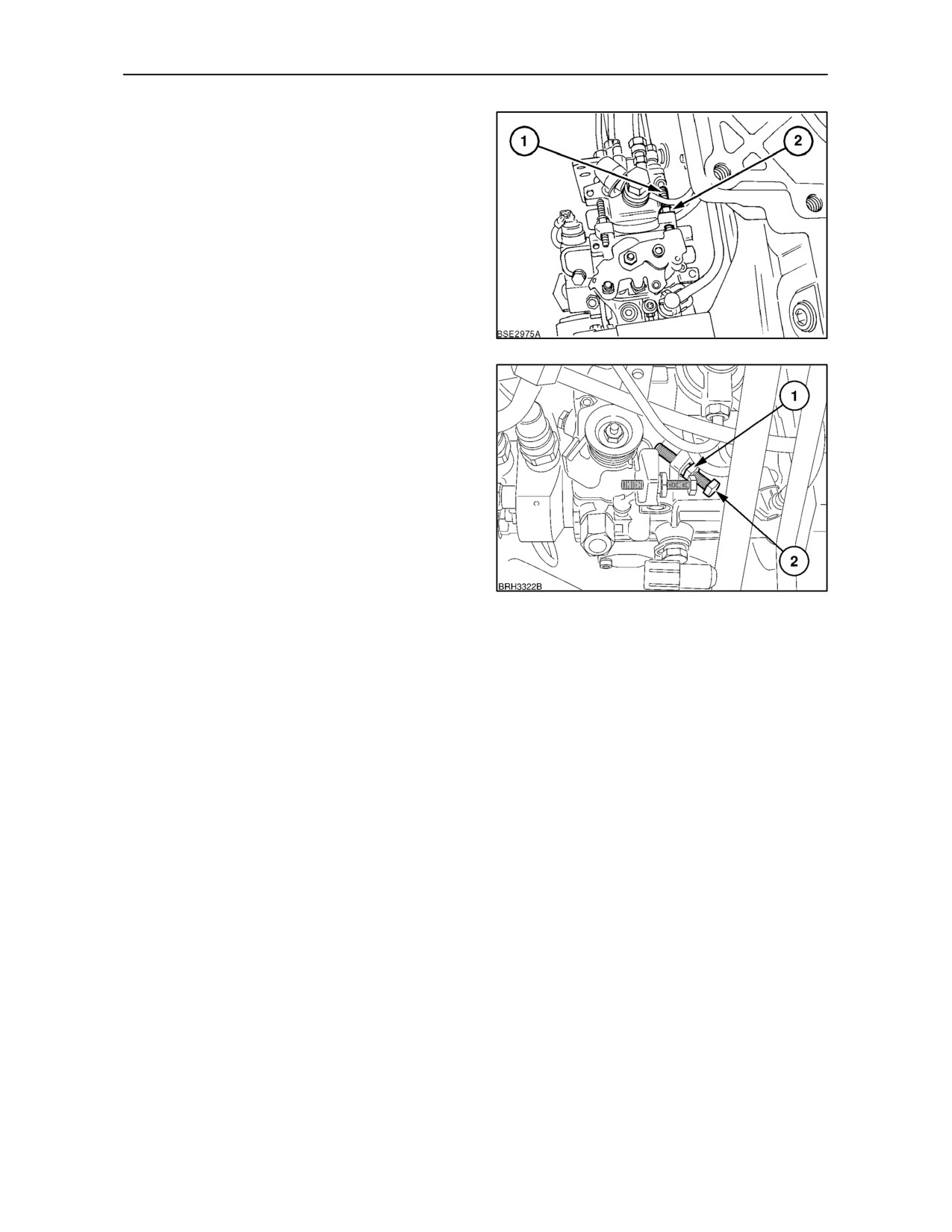
NOTE: If the tyres are ballasted with a calcium
chloride/water solution, a special tyre gauge should
be used as the solution will corrode a proprietary type
109
gauge. Check pressure with the valve stem at the
bottom.
4--53
SECTION 4 -- LUBRICATION AND MAINTENANCE
OPERATION 40
ENGINE IDLE SPEED
6 cylinder models
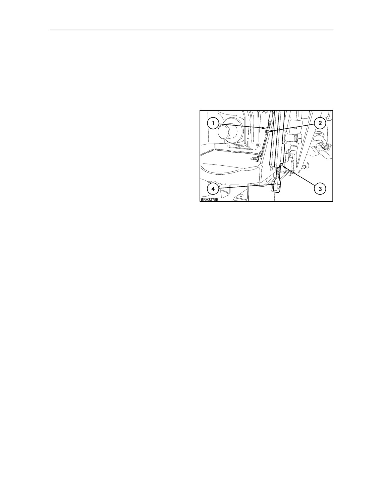
Loosen the locknut (2) and turn the stop screw (1) to
adjust the engine idle speed.
Engine idle speed: 800 -- 850 rpm
110
4 cylinder models
Loosen the locknut (1) and turn the stop screw (2) to
adjust the engine idle speed.
Engine idle speed: 800 -- 850 rpm
111
4--54
SECTION 4 -- LUBRICATION AND MAINTENANCE
OPERATION 41
AUTOMATIC PICK--UP HITCH
Place a load on the pick-up hitch hook. A trailer or
implement is suggested. Ensure that the hitch will
latch and unlatch satisfactorily. If adjustment is
necessary, remove the load from the hitch before
adjusting the latch.
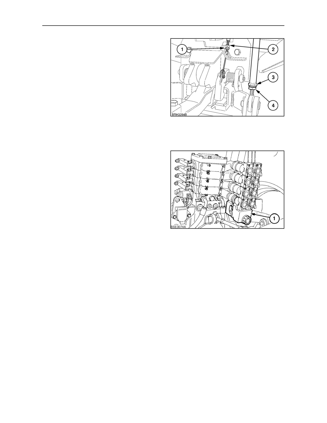
Drop Down Hitch
Loosen the locknut (3) and remove the clevis bolt (4).
Slide the lift rod from the hitch and rotate to adjust the
length. Refit the lift rod to the hitch and temporarily
replace the clevis bolt. Repeat the procedure on the
the opposite lift rod ensuring an equal amount of
adjustment is applied.
Test hitch operation to ensure that both lift rods
support the hitch equally at the start of raise. Check
the hitch will latch and unlatch correctly, then tighten
the lift rod locknuts and clevis bolts.
When fully raised ensure that the hydraulic system
112
relief valve does not blow or that the hitch lift rods are
not under tension. Both these symptoms indicate
that the hitch lift rods are too short.
If the tension on the hitch release cable requires
adjustment, loosen the locknut
(2). Adjust the
tension by re--positioning the nut (1) on the cable
adjuster. After re--setting, check for satisfactory
operation and re--tighten the locknut.
4--55
SECTION 4 -- LUBRICATION AND MAINTENANCE
Hydraulic Extending Hitch
Loosen the locknut (4) and turn the adjuster (3) on
each lift rod equally. Ensure that both hitch lift arms
are supporting the hitch equally at the start of raise.
Check that the hitch will latch and unlatch correctly
and re--tighten the locknut.
When fully raised ensure that the hydraulic system
relief valve does not blow or that the hitch lift rods are
not under tension. Both these symptoms indicate
that the hitch lift rods are too short.
If the tension on the hitch release cable requires
adjustment, loosen the locknut
(2). Adjust the
113
tension by re--positioning the nut (1) on the cable
adjuster. After adjustment, check for satisfactory
operation and re--tighten the locknut.
OPERATION 42
CHECK REMOTE CONTROL VALVE
DRAIN BOTTLES
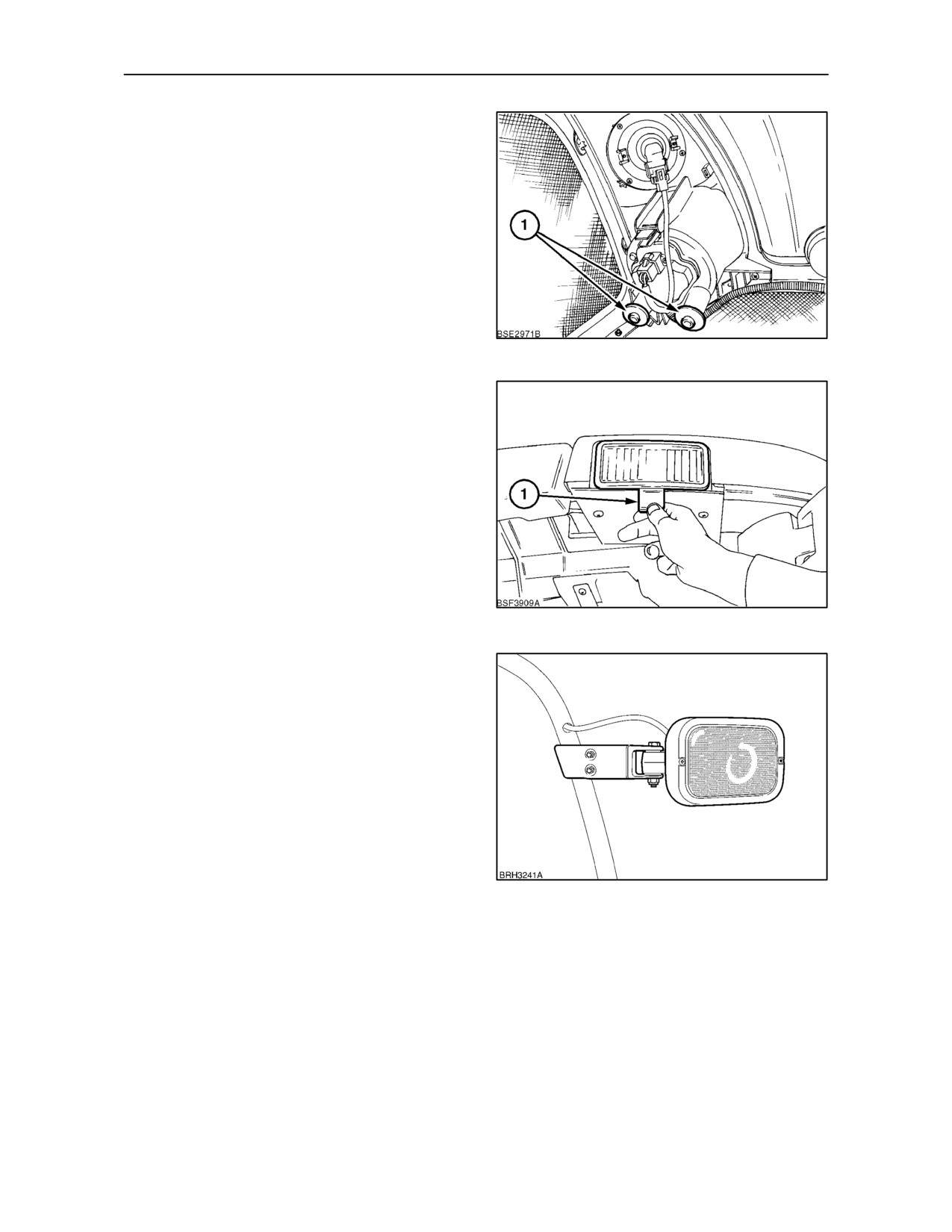
Every time a hydraulic hose is connected and
disconnected, a small amount of oil is discharged
from the remote control valve coupler. Drain bottles
(1) are located below each remote valve to catch the
discharged oil.
Visually check the oil level in the bottles. If necessary,
unclip the the bottle, remove the cap and empty the
oil into a suitable container. Re--install the bottle,
ensuring it is correctly seated below the valve.
114
4--56
SECTION 4 -- LUBRICATION AND MAINTENANCE
OPERATION 43
HEADLIGHT AND WORKLAMP
ADJUSTMENT
Headlights
To avoid blinding on coming drivers, adjust the angle
of the headlight beams.
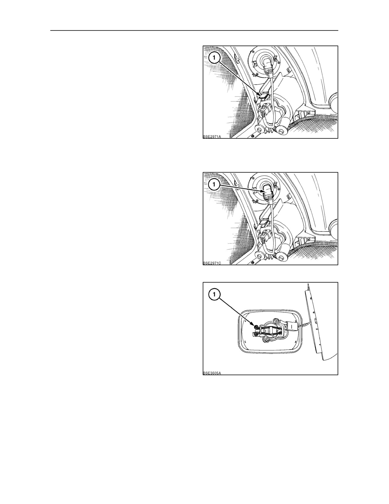
Each headlight is adjusted by rotating the two
adjusters (1) clockwise or anti--clockwise according
to the amount of correction required.
115
Worklamps
Dependant upon model and specification, adjustable
worklamps may be installed on the front and rear of
of the cab roof, low down at the front of the cab or on
the rear fenders. Non--adjustable worklamps are
mounted on the front of the hood , adjacent to the
headlights.
Roof Mounted with Standard Cab
Cab roof mounted worklamps are adjusted by
moving the protruding lever
(1), backwards or
forwards.
116
Grab Rail Mounted with Low Profile Cab
To adjust the position of the light, grasp the lamp
assembly and rotate upwards or downwards .
117
4--57
SECTION 4 -- LUBRICATION AND MAINTENANCE
OPERATION 44
BULB REPLACEMENT
Headlights and Hood--mounted Worklamps
IMPORTANT: All headlights and worklamps have
halogen bulbs. Never touch a halogen bulb with the
fingers. Natural moisture in the skin mayu cause the
bulb to fail prematurely when switched on. Always
use a clean cloth or tissue when handling halogen
bulbs.
The headlights and two non--adjustable worklamps
are mounted in a moulded unit attached to the front
118
hood assembly. All bulbs are accessible from the
rear of the lamp unit inside the hood area.
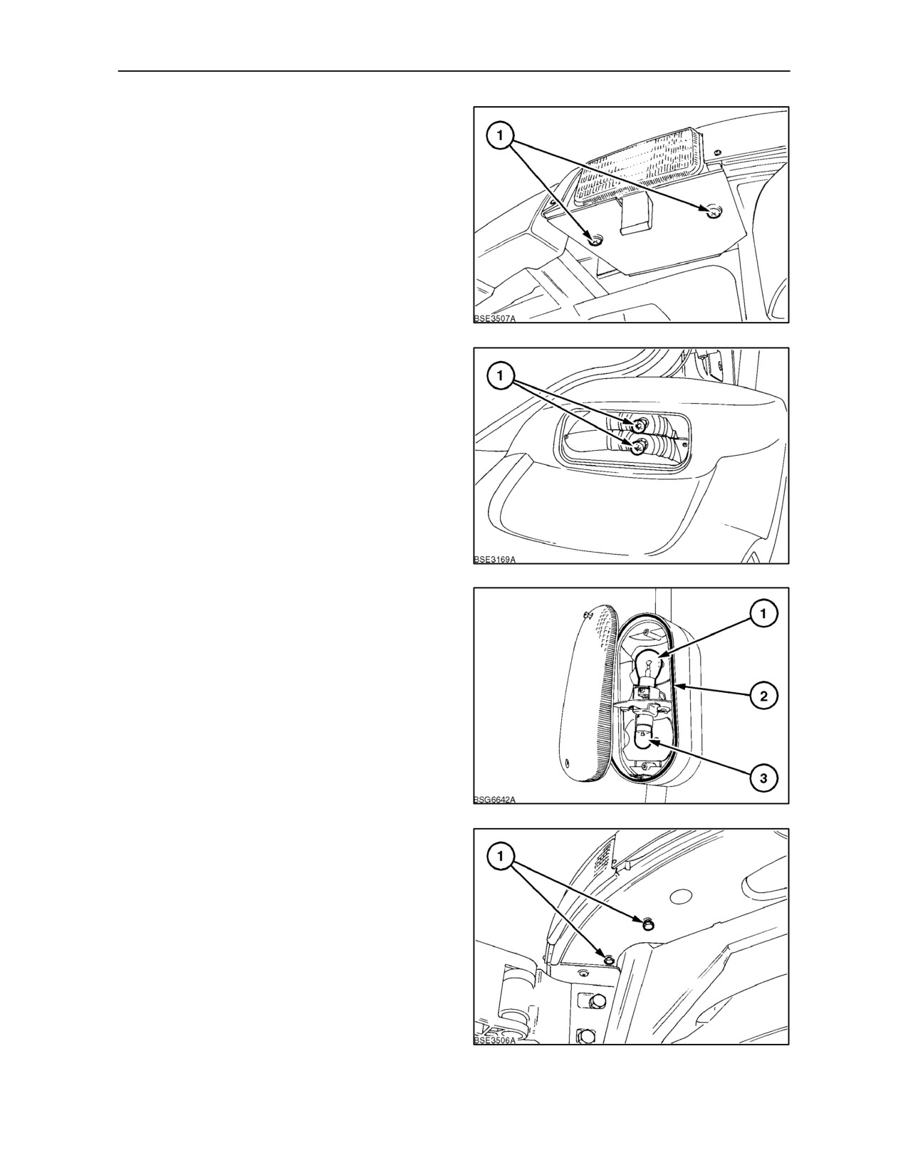
To remove bulb from front headlight assembly, raise
hood as previously described in this section. Press
the retaining clip (1) to unhinge the rear part of the
headlight. Detach the retaining spring and remove
the bulb.
To remove the bulb from the integral worklamp
simply rotate the bulb holder assembly
(1)
anti--clockwise approximately 20 degrees. The bulb
can then be removed by pressing in the bulb and then
releasing it.
119
Adjustable Worklamps
Grabrail mounted worklamps
To replace the bulbs on the grabrail mounted
worklamps, remove the two retaining screws. Pull
out the lens housing from the main lamp housing.
Squeeze together the ends of the wire retaining clip
(1)
and pull the bulb holder from the
assembly.Remove the bulb making sure to use a
clean cloth or tissue.
120
4--58
SECTION 4 -- LUBRICATION AND MAINTENANCE
Cab roof mounted worklamps
Remove the two retaining screws (1) and lower the
lamp assembly from the roof. Rotate the bulb holder
counter--clockwise and pull from the lamp
housing.Rotate the bulb counterclockwise and
remove from the bulb holder making sure to use a
clean cloth or a tissue.
121
Turn/Position Lights
To gain access to the lower rear turn/position bulbs
remove the two retaining screws. Remove the lens.
To remove the bulbs (1) rotate counter clockwise.
122
The front turn/position lamps are located on the
grabrails. Remove the two retaining screws.Remove
the lens. To remove the turn indicator bulb (1) or the
position bulb (3) rotate counter clockwise. When
re--fitting the lens ensure the sealing rubber (2) is
fully seated in the lamp housing.
123
Turn/Position Lights with Standard Cab
(North America Only)
The turn position lamps (Front and Rear) are located
in the cab roof. Remove the two retaining bolts (1)
and pull the lamp assembly from the housing. Rotate
the harness connector counter--clockwise to remove
the bulb holder from the lamp housing.
124
4--59
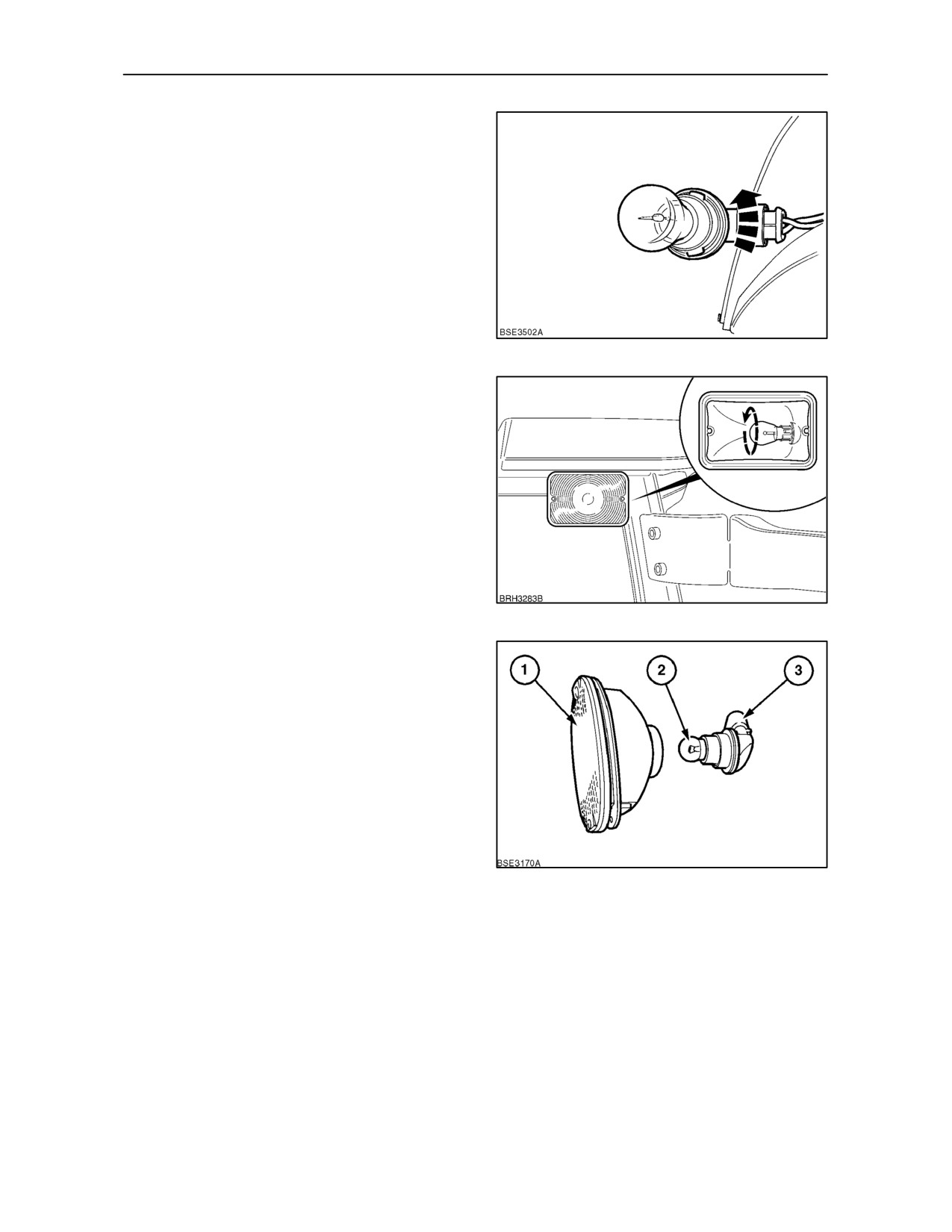
SECTION 4 -- LUBRICATION AND MAINTENANCE
To remove the bulb rotate the bulb
counter--clockwise and pull from the bulb holder.
125
Turn/Position Lights with Low Profile Cab
(North America Only)
To gain access to the bulb remove the two screws
retaining the lens and withdraw the lens from the light
unit.
To remove the bulb rotate the bulb anti--clockwise
and pull from the bulb holder. Re--assemble in the
reverse order.
126
Courtesy Lights
Remove the two retaining screws.Remove the lens
housing assembly (1) from the cab roof. Disconnect
the harness connector and remove the light
assembly. To remove the bulb housing (3) rotate the
harness connector counter clockwise. To remove the
bulb (2) rotate counter clockwise.
127
4--60
SECTION 4 -- LUBRICATION AND MAINTENANCE
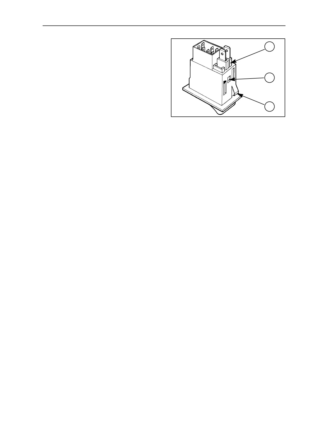
Rocker Switch Bulbs
1
Certain of the rocker switches are internally
illuminated, the bulb being removeable from the rear
of the switch assembly.
The switch assembly is retained by a sprung tag (3)
2
at either end. Use a small screwdriver to pry one end
of the rocker switch from the sheet metal and
withdraw the switch assembly.
3
To change a bulb, press in the tag (2) using a small
screwdriver and pull the bulb retainer (1) from the
back of the assembly. The bulbs are of the capless
128
type, rated at 1.2w and are a push fit in the retainer.
After changing the bulb, push the retainer into the
back of the switch assembly until the tag locates in
the aperture. Re-install the switch assembly.
4--61
SECTION 4 -- LUBRICATION AND MAINTENANCE
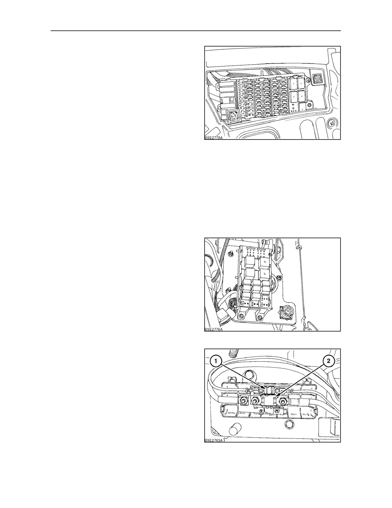
OPERATION 45
FUSES AND RELAYS
The fuse box is located behind a panel on the right
--hand side of the instrument console.
To check or change fuses, remove the right--hand
panel from the instrument console. Pull off the lid of
the fuse box to gain access to the fuses and relays.
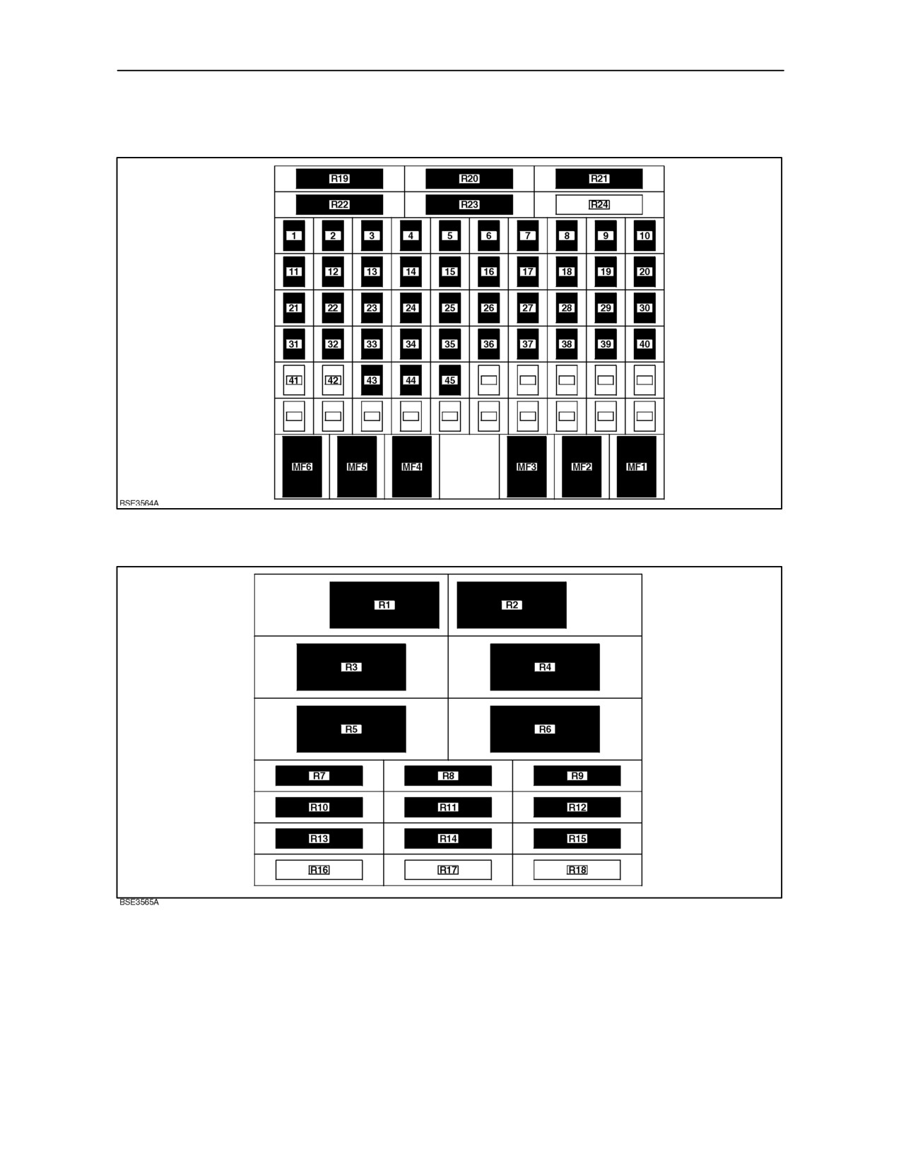
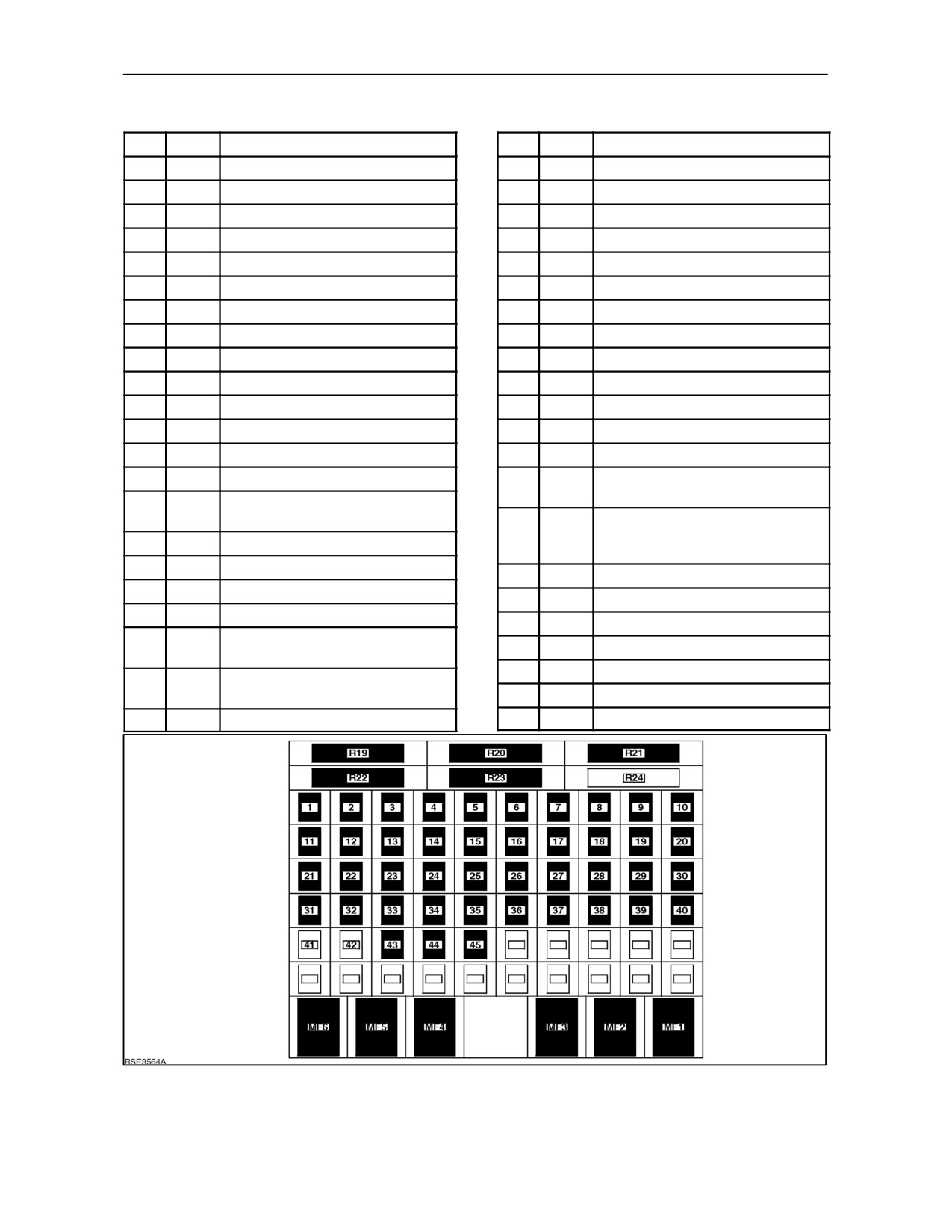
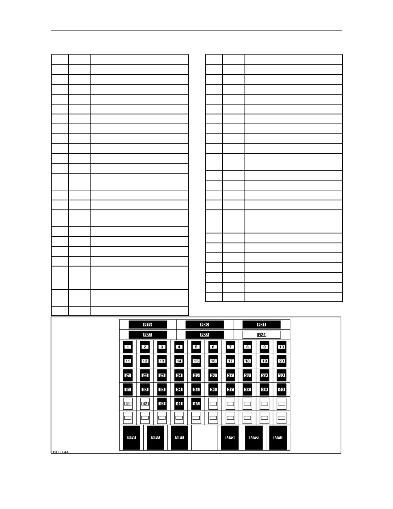
The fuses and relays are shown diagrammatically in
Figures 132 and 133. In additon to the main fuses
there are additional ‘maxi’ fuses which are provided
to protect the main fuses and electrical circuitry.
129
There is provision for 60 fuses although they may not
all be fitted to your tractor. In addition, certain items
of equipment may not be installed on your tractor.
However, the fuses for these features are still fitted
and may be used as spares.
IMPORTANT: Do not replace a blown fuse with
another of a different rating.
The fuses are numbered and colour--coded. Their
position and rating are shown in the chart on the next
page.
More relays are located at the front of the right--hand
instrument console.
130
In addition to the fuses in the internal fuse box , there
are also extra fuses located on the battery tray. A
250 amp ‘MEGA‘ fuse which protects the main
electrical system and two
30 amp fuses which
protect the front lift electrical system and the
electronics supply.
131
4--62
SECTION 4 -- LUBRICATION AND MAINTENANCE
FUSE AND RELAY LOCATIONS
Fusebox, Relays and Maxi--Fuses
132
Relays
133
4--63
SECTION 4 -- LUBRICATION AND MAINTENANCE
RELAY DESCRIPTIONS
12x12 -- With and Less Cab
Refer to Figures 132/ 133
Relay
Function
13
Blank (Less cab)
Engine Run and Cold Start (With cab--
1
Blank (Less cab)
Mechanical Engines Only)
Windshield Wiper -- Front
14
Reverse Alarm
2
Blank (Less cab)
Windshield Wiper -- Rear
15
A/C Clutch Relay
3
Ignition Relay
16
Blank
4
Lights
17
Blank
5
Starter
18
Blank
6
Blower Motor
19
Worklamps -- Front Lower
7
Dip Beam Headlamps
20
Worklamps -- Rear Lower
8
Stoplamps
21
Electrical Supply
9
Main Beam Headlamps
22
Blank
10
Hydraulic Trailer Brake Pressure
23
Blank
11
Hydraulic Trailer Brake Supply
24
Blank
12
Stoplamps Switch Feed (Less cab)
+ Pnuematic Trailer Brake (With cab)
16x16 and 24x24 -- Less Cab
Refer to Figures 132/ 133
Relay
Function
13
Engine Cold Start Advance + Engine
Shutdown (Mechanical Engines Only)
1
Blank
14
Reverse Alarm
2
Blank
15
Blank
3
Ignition Relay
16
Blank
4
Lights
17
Blank
5
Starter
18
Blank
6
Blank
19
Worklamps -- Front Lower
7
Dip Beam Headlamps
20
Worklamps -- Rear Lower
8
Stoplamps
21
Electrical Supply
9
Main Beam Headlamps
22
Blank
10
Pneumatic Trailer Brake Pressure
23
Blank
11
Hydraulic Trailer Brake Supply
24
Blank
12
Stoplamps Switch Feed
4--64
SECTION 4 -- LUBRICATION AND MAINTENANCE
16x16 and 24x24 -- With Cab
Refer to Figures 132/ 133
Relay
Function
13
Engine Cold Start Advance
(Mechanical Engines Only)
1
Front Windscreen Wiper Module
14
Reverse Alarm
2
Rear Window Wiper Module
15
A/C Clutch Relay Feed
3
Ignition Relay
16
Electronic Remote Valve Power
4
Side/Tail Lights and Illumination
(16 x 16 Transmissions Only)
5
Starter
17
Blank
6
Blower Motor
18
Blank
7
Dipped Beam Headlamps
19
Front Lower Worklamps (Hood)
8
Stoplamps
20
Rear Lower Worklamps
9
Main Beam Headlamps
21
Electrical Supply
10
Pneumatic Trailer Brake Supply
22
Blank
11
Hydraulic Trailer Brake Supply
23
Blank
12
Stoplamps Switch Feed and Pneumatic
24
Blank
Brakes
4--65
SECTION 4 -- LUBRICATION AND MAINTENANCE
Mini Fuses 12x12 -- Less Cab
No.
Amps
Circuit
23
15
Sidelamps LH
1
10
Handbrake Lamp
24
10
Illumination
2
--
Blank
25
15
Dip Beam Headlamps
3
--
Blank
26
15
Main Beam Headlamps
4
--
Blank
27
15
Front Headlamps
5
--
Blank
28
--
Blank
6
--
Blank
29
--
Blank
7
20
Main Lights
30
15
Rear/Lower Worklamps
8
20
Starter Switch
31
--
Blank
9
--
Blank
32
30
Flasher Unit
10
--
Blank
33
25
Diagnostic Connector
11
--
Blank
34
10
Instrument Cluster
12
--
Blank
35
10
SCM (Small Control Module)
13
15
Stoplamps
36
10
Instrument Cluster
14
15
Main Light Switch + Flasher Unit
37
15
Front Switch Group +
Transmission Ignition
15
20
Stoplamp Switch + Hydraulic
Trailer Brake + Pedal Latch
38
10
SCM + Switch Panel + Ground
Speed + Rear PTO Warning Lamp
16
--
Blank
+ PTO Brake
17
--
Blank
39
10
Seat
18
15
Seat
40
--
Blank
19
--
Blank
41
--
Blank
20
10
Back up Alarm + Transmission
42
--
Blank
Diagnostic
43
10
Starter Switch (Run Position)
21
15
Grid Heater + Water In Fuel
Sensor + Brake Fluid Level Switch
44
--
Blank
22
15
Sidelamps RH
45
25
Front Ignition
134
4--66
SECTION 4 -- LUBRICATION AND MAINTENANCE
Mini Fuses 12x12 -- With Cab
No.
Amps
Circuit
23
15
Sidelamps LH
1
10
Interior and Courtesy Lights
24
10
Illumination
2
25
Cigar Lighter + Power studs
25
15
Dip Beam Headlamps
3
10
A/C Clutch
26
15
Main Beam Headlamps
4
10
Accessory Sockets
27
15
Front Worklamps (Hood)
5
30
Blower Motor
28
15
ECU Worklamp
6
10
Radio KAM + Worklamp ECU
29
30
ECU Worklamp
7
20
Main Lights + Hazard Switch
30
15
Rear Lower Worklamps
8
20
Starter Switch
31
15
ECU Worklamp
9
25
Loader
32
30
Flasher Unit
10
--
Blank
33
25
Diagnostic Connector + Engine
ECU
11
10
Front and Rear Windscreen Wiper
34
10
Instrument Cluster
12
10
Wiper Switch and Rear Wiper
Park
35
10
SCM (Small Control Module)
13
15
Stoplamps
36
10
Instrument Cluster Ignition
14
15
Main Light Switch + Turn Signal
37
15
Transmission Ignition
15
20
Stoplamps Switch + Hydraulic-
38
10
SCM + Switch Panel + Ground
Trailer Brake + Pedal Latch
Speed PTO Switch + Rear PTO
Warning Lamp + PTO Brake
16
15
Pneumatic Trailer Brake
39
10
Seat
17
25
Accessory Sockets
40
10
Radio
18
15
Blower Motor + seat
41
--
Blank
19
--
Blank
42
--
Blank
20
10
Radar Socket + Transmission
Diagnostic Socket + ADICKeypad
43
10
Starter Switch (Run Position)
+ Radar + Backup Alarm
44
25
Front Implement Power Socket
21
15
Grid Heater + Water In Fuel
45
25
Front Ignition + 8 Amp Socket
Sensor + Brake Fluid Level Switch
22
15
Sidelamps RH
135
4--67
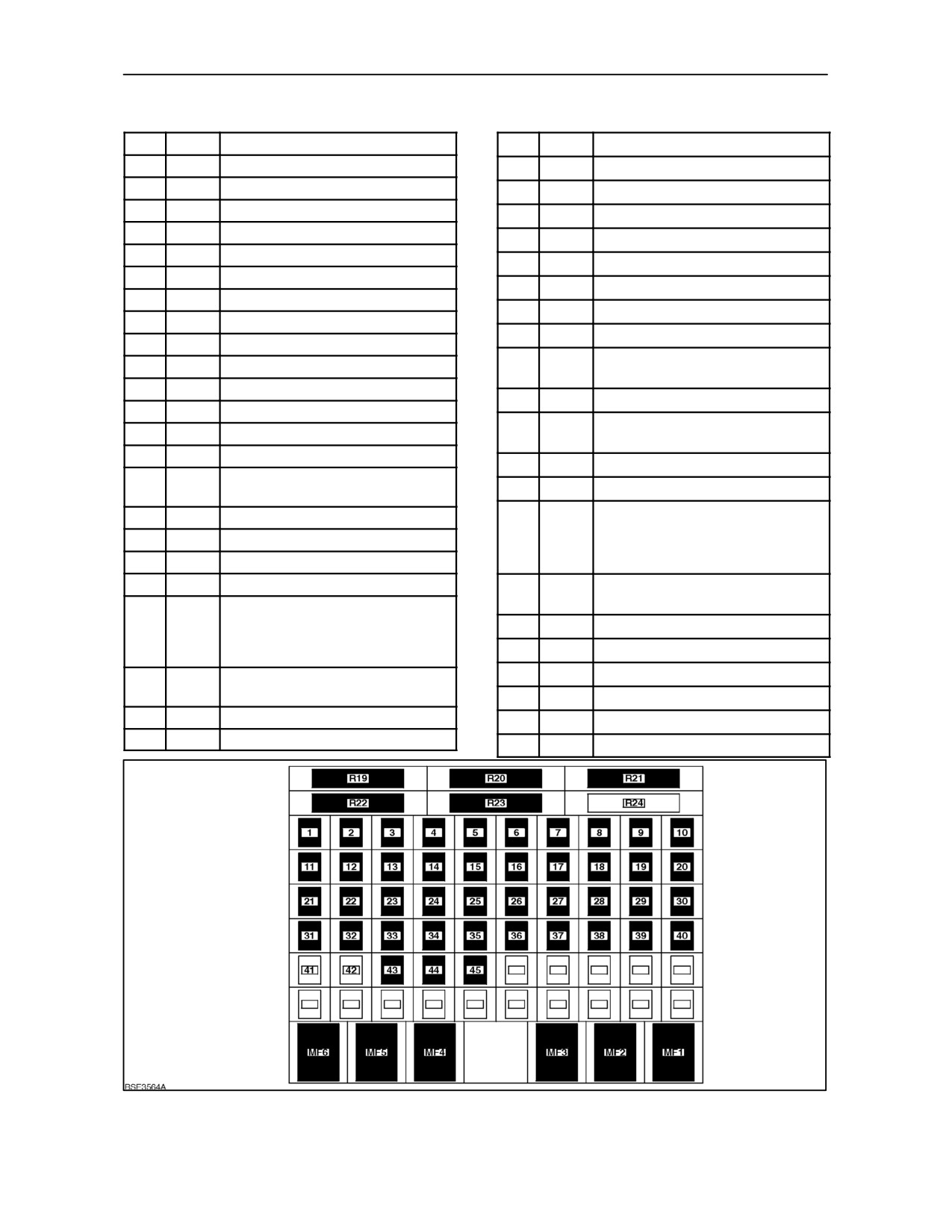
SECTION 4 -- LUBRICATION AND MAINTENANCE
Mini Fuses 16x16 and 24x24 -- Less Cab
No.
Amps
Circuit
24
10
Illumination
1
10
Handbrake Lamp
25
15
Dip Beam Headlamps
2
--
Blank
26
15
Main Beam Headlamps
3
--
Blank
27
15
Front Worklamps
4
--
Blank
28
--
Blank
5
--
Blank
29
--
Blank
6
--
Blank
30
15
Rear Lower Worklamps
7
20
Main Lights + Hazard Switch
31
--
Blank
8
20
Starter Switch
32
30
Flasher Unit
9
25
Loader
33
25
Diagnostic Connector + Engine
10
--
Blank
ECU
11
--
Blank
34
10
Instrument Cluster
12
--
Blank
35
10
DC Mem + Standard Control
13
15
Stoplamps
Module + Auxiliary Control Module
14
15
Main Light Switch + Flasher Unit
36
10
Instrument Cluster Ignition
15
20
Stoplamp Switch + Hydraulic
37
15
Transmission Ignition
Trailer Brake + Pedal Latch
38
10
HPL + Switch Panel + Ground
16
--
Blank
Speed PTO + SCM + Rear PTO
17
--
Blank
WarningLamp + PTO Brake +
18
15
Seat
Display Of Gears Connector
19
10
Blank
39
10
HPL + Seat + Hand Throttle +
Armrest
20
10
Standard Control Module Diag-
nostic + Auxiliary Control Module
40
--
Blank
Diagnostic + Keypad+Re-
41
10
Front Suspension and PTO
verse Alarm + Radar
42
10
Front Suspension
21
15
Grid Heater + Water In Fuel
Sensor + Brake Fluid Level Switch
43
10
Starter Switch (Run Position)
22
15
Sidelamps RH
44
25
Front Implement Power Socket
23
15
Sidelamps LH
45
--
Blank
136
4--68
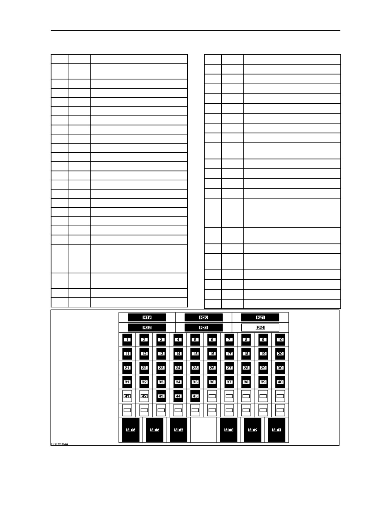
SECTION 4 -- LUBRICATION AND MAINTENANCE
Mini Fuses 16x16 and 24x24 -- With Cab
No.
Amps
Circuit
24
10
Illumination
1
10
Interior and Courtesy Lights +
25
15
Dip Beam Headlamps
Handbrake Lamp
26
15
Main Beam Headlamps
2
25
Cigar Lighter + Power Studs
27
15
Front Worklamps (Hood)
3
10
A/C Clutch
28
15
ECU Worklamp
4
10
Accessory Sockets
29
30
ECU Worklamp
5
30
Blower Motor
30
15
Rear Lower Worklamps
6
10
Radio KAM + Worklamp ECU
31
15
ECU Worklamp
7
20
Main Lights + Hazard Switch
8
20
Starter Switch
32
30
Flasher Unit
9
25
Loader
33
25
Diagnostic Connector + Engine
ECU
10
--
Blank
34
10
Instrument Cluster B+
11
10
Front and Rear Windscreen Wiper
35
10
DC Mem + SCM + ACM
12
--
Wiper Switch and Rear Wiper Park
13
10
Stoplamps
36
10
Instrument Cluster Ignition
14
15
Main Light Switch + Flasher Unit
37
15
Transmission Ignition
15
20
Stoplamp Switch + Pedal Latch
38
10
Rear PTO Switch + Rear PTO
Lamp + HPL + SCM + Ground
16
15
Trailer Brake
Speed PTO + Display Of Gears
17
25
Accessory Sockets
Connector
18
15
Blower Motor + Seat
39
10
HPL + Seat + Armrest + EDC +
19
--
Blank
EHR Levers (16 x 16 Only)
20
10
Radar Socket + Transmission
40
10
Radio
Diagnostic Socket + Auxiliary
41
15
Front Suspension and PTO + EHR
Diagnostic Socket + ADIC KeyPad
Levers (16 x !6 Only)
+ Radar + BackUp Alarm
42
10
Front Suspension
21
10
Grid Heater + Water In Fuel
Sensor + Brake Fluid Level Switch
43
10
Starter Switch (Run position)
22
15
Sidelamps RH
44
25
Front Implement Power Socket
23
15
Sidelamps LH
45
25
Front Ignition + 8 Amp Socket
137
4--69
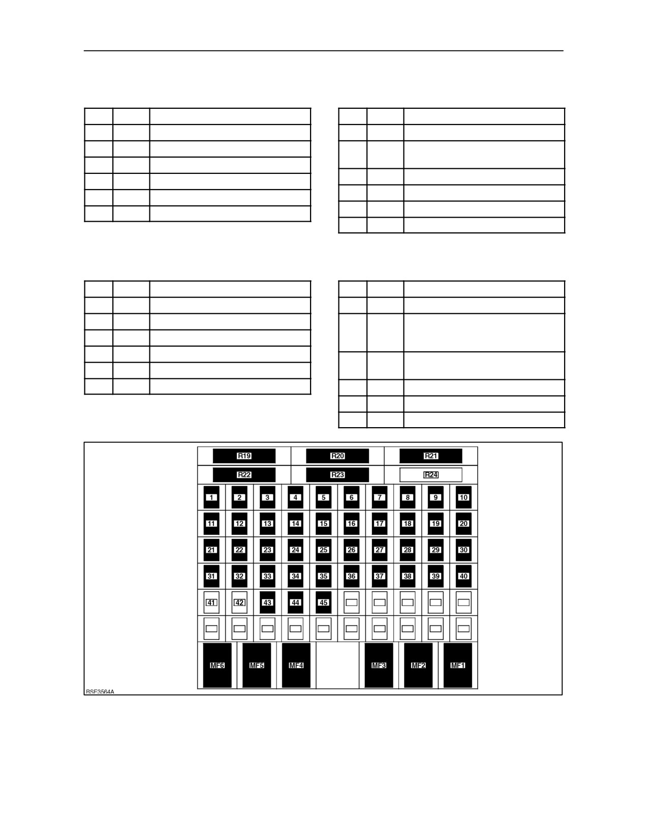
SECTION 4 -- LUBRICATION AND MAINTENANCE
Maxi Fuses 12 x 12 -- Less Cab
Maxi Fuses 12 x 12 -- With Cab
No.
Amps
Protected Components
No.
Amps
Protected Components
MF1
80
Engine
MF1
80
Engine, Ignition Relay
MF2
30
Lighting
MF2
30
Lighting, Ignition Switch, Radio,
Worklamp ECU
MF3
40
B + KAM ADIC
MF3
40
B + KAM ADIC, SCM
MF4
40
Implement Socket Rear
MF4
40
Implement Socket Rear
MF5
100
Lighting
MF5
100
Lighting
MF6
80
Accessories Cab
MF6
80
Accessories Cab
Maxi Fuses 16 x 16 and 24 x 24 -- Less Cab
Maxi Fuses 16 x 16 and 24 x 24 -- With Cab
No.
Amps
Protected Components
No.
Amps
Protected Components
MF1
80
Engine
MF1
80
Engine, Ignition Relay
MF2
30
Lighting
MF2
30
Lighting, Ignition Switch, Main
Lighting Switch, Radio, Worklamp
MF3
40
B + KAM ADIC
ECU
MF4
40
Implement Socket Rear
MF3
40
B + KAM ADIC, Engine ECU,
MF5
100
Lighting
Transmission ECU
MF6
80
Accessories Cab
MF4
40
Implement Socket Rear
MF5
100
Lighting
MF6
80
Accessories Cab
138
4--70
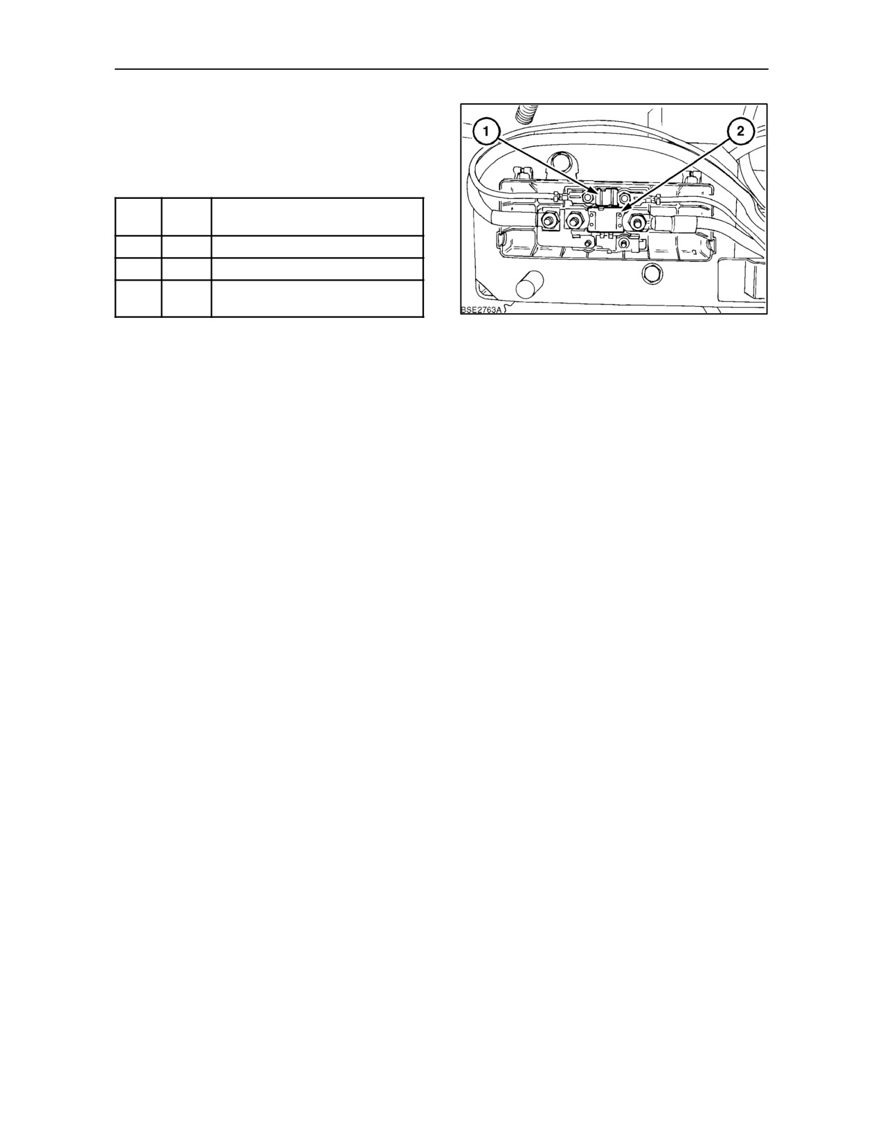
SECTION 4 -- LUBRICATION AND MAINTENANCE
POWER FUSES
All Models
Fuse
Amps
Protected Supply
No.
PF1
30
Power E Electronic Supply
PF2
250
Power B + Main Supply
PF3
30
Power B + Front Implement
Socket
139
4--71
SECTION 4 -- LUBRICATION AND MAINTENANCE
OPERATION 46
CLEANING THE TRACTOR
Cab Interior
When the soft trim material inside the cab becomes
dirty, it should be wiped clean. Dip a cloth in a warm
water/detergent solution and squeeze out as much
of the water as possible.
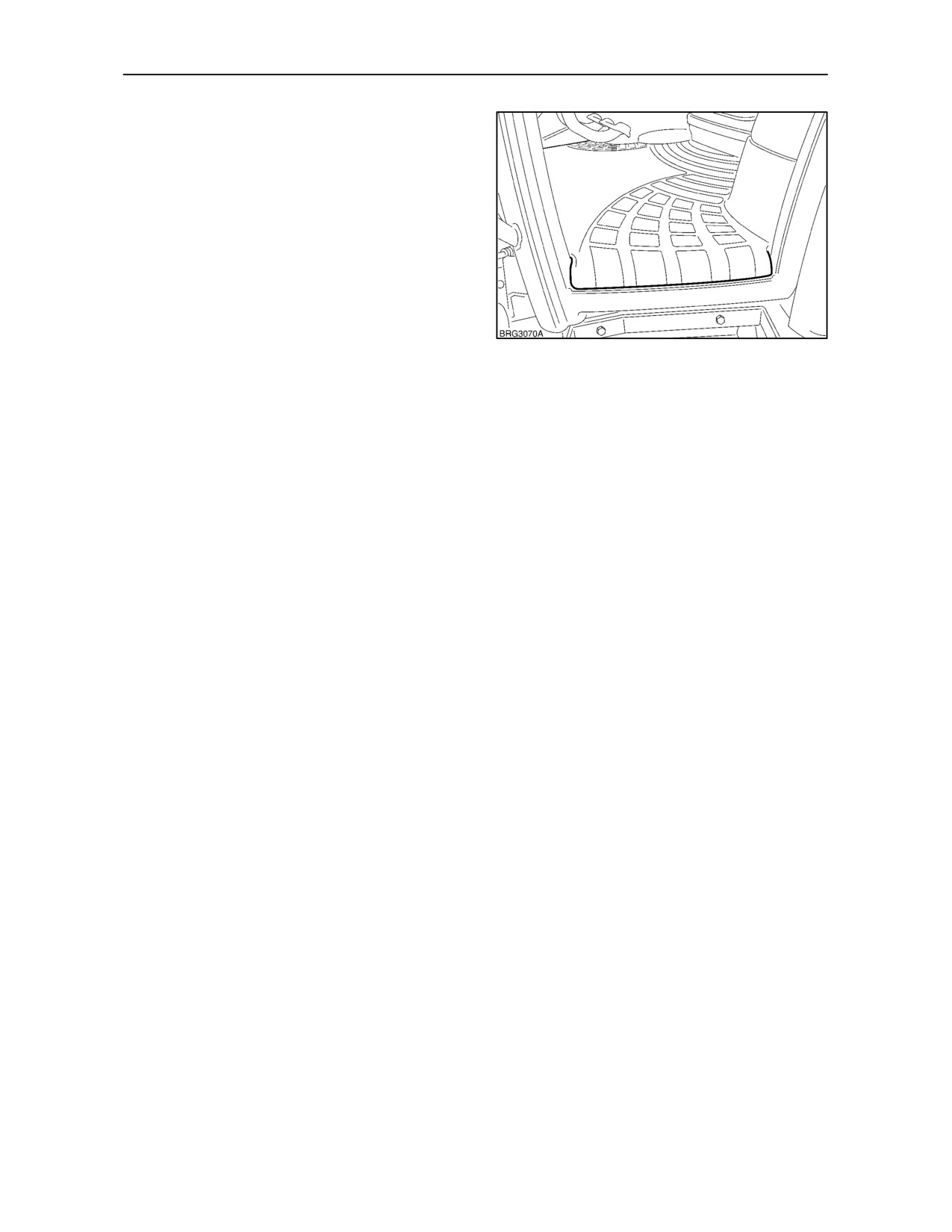
The rubber floor covering is designed to allow water
to flow out through the open doors. Wash the
covering carefully and allow to dry naturally. Avoid
getting water under the mat.
140
NOTE: When operating with chemical sprayers,
clean the interior of the cab on a more frequent basis
to prevent a build up of chemical residue.
Cleaning the Seat and Seat Belt
The belt may be sponged with clean, soapy water. Do
not use solvents, bleach or dye on the belt as these
chemicals will weaken the webbing.
Replace the belt when it shows signs of fraying,
damage or general wear.
Do not use solvents to clean the seat. Use only warm
water with a little detergent added or a proprietry
brand of automotive upholstery cleaner. Avoid
wetting the seat more than is absolutely necessary.
4--72
SECTION 4 -- LUBRICATION AND MAINTENANCE
Cleaning the Exterior of the Tractor
Maintenance of the paintwork is normally carried out
by washing, at intervals that depend on the
conditions of use and the environment. In areas
prone to atmospheric pollution and coastal zones,
washing should be carried out more frequently,
whereas if organic or chemical substances are
present, wash immediately after the tractor is used.
Use a low pressure water spray, sponge down with
a solution of automotive shampoo and water, rinsing
the sponge frequently. Rinse the tractor thoroughly
and dry off.
Avoid washing the tractor if it is hot or has been
standing in the sun. This will help to protect the shine
on the paintwork.
Protect the paintwork by means of periodical
polishing with special products
(silicone waxes)
which are available from your authorised dealer. Use
wax polish should the paintwork start to dull as this
has a slightly abrasive action.
NOTE: When carrying out operations involving
materials or crops which may become airborne,
frequently check the tractor for build up of debris
around the radiator, engine and exhaust system to
prevent overheating or the possibility of catching fire.
In the event of abrasions or deep scratches that
expose the metal under the paintwork, the area
concerned will need to be retouched and treated
immediately with specified original products as
follows:
--
Rub down the immediate area surrounding the
damage with fine abrasive paper.
--
Apply a coat of primer.
--
Leave to dry and then rub down with fine abrasive
paper to ’key’ the surface.
--
Apply the paint. For best results apply several
light applications of paint rather than one heavy
coat. Paint and primer are available from your
authorised dealer.
--
When fully dry, apply a good quality polish and
buff to a shine.
4--73
SECTION 4 -- LUBRICATION AND MAINTENANCE
PROTECTING THE ELECTRONIC AND
6. Position the welder earth cable clamp as close to
ELECTRICAL SYSTEMS DURING BATTERY
the welding area as possible.
CHARGING OR WELDING
7. If welding is to be carried out in close proximity to
a computer module, then the module should be
Precautions
removed from the tractor. It is recommended that
this procedure be carried out by an authorised
To avoid damage to the electronic/electrical
dealer.
systems, always observe the following:
8. Never allow welding cables to lay on, near or
1. Never make or break any of the charging circuit
across any electrical wiring or electronic
connections, including the battery connections,
component while welding is in progress.
when the engine is running.
9. Always disconnect the negative cable from the
2. Never short any of the charging components to
batteries when charging the batteries in the
earth.
tractor with a battery charger.
3. Do not use a slave battery of higher than 12 volts
WARNING
nominal voltage.
Batteries contain sulphuric acid. In case of contact
with skin, flush the affected area with water for five
4. Always observe correct polarity when installing
minutes. Seek medical attention immediately. Avoid
the batteries or using a slave battery to jump start
contact with the skin, eyes or clothing. Wear eye
the engine. Follow the instructions in the
protection when working near batteries.
operator’s manual when jump starting the
tractor. Connect positive to positive and negative
to negative.
IMPORTANT: Failure to disconnect the two earth
cable connections at the battery prior to charging the
5. Always disconnect the earth cable from the
batteries or welding on the tractor or attached
batteries before carrying out arc welding on the
implement will result in damage to the electronic and
tractor or on any implement attached to the
electrical systems.
tractor.
4--74
SECTION 5
FAULT FINDING
INTRODUCTION
The following information is intended as a guide to
assist in identifying and correcting possible tractor
malfunctions and fault conditions.
The information provided is as follows:
• ERROR CODES
• SYSTEM TROUBLESHOOTING
ERROR CODES
Your tractor makes extensive use of electronics to
control and monitor major components within the
driveline and hydraulic system. In the unlikely event
of a fault occurring in one of these areas, the
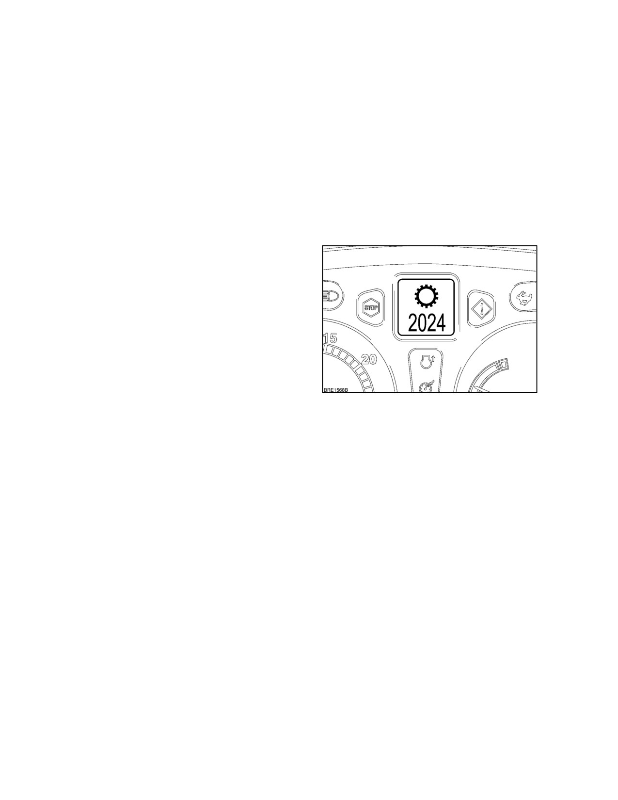
malfunction will be identified with a symbol (1) and a
four-digit error code in the Dot Matrix Display on the
instrument panel. The first digit(s) of each number
provide the general location of the fault and the
susequent numbers confirm the exact nature of the
fault.
First Digit
Area of Fault
1
0------
General fault
SYSTEM TROUBLE SHOOTING
1------
Electronic draft control
2------
Transmission
The following information lists possible problems,
3------
Engine
their cause and corrective action. The systems are
4------
Electronic Remote Valves
listed as follows:
5------
Rear PTO
6------
Four wheel drive
Subject
Page
7------
Differential lock
Engine
5--2
8------
Front Power Take Off
9------
Front 3--Point Hitch
Transmission
10------
4WD Front Axle Suspension
-- Synchro Command -- 12 x 12
5--5
14------
Instrument cluster
-- Dual Command -- 24 x 24
5--6
15------
Fast Steer
-- Electro Command -- 16 x 16 and 17 x 16
5--7
Hydraulics
5--8
The code indicates the faulty circuit or sensor and the
type of fault, e.g., open circuit, short circuit, etc. Each
3-point linkage
5--9
error code will be supported by the relevant symbol
Brakes
5--10
displayed above the number. In this event, the tractor
will require the attention of your New Holland dealer.
Cab
5--10
Electrical
5--11
Should a fault occur causing the tractor to become
disabled, an error code will be displayed in the
instrument panel. If this should happen and you are
unable to rectify the fault yourself, contact your
authorised dealer and report the error code
displayed.
5--1

SECTION 5 -- FAULT FINDING
ENGINE
PROBLEM
POSSIBLE CAUSE
CORRECTION
Engine will not start
Incorrect starting procedure.
Review starting procedure.
or is difficult to start
Low or no fuel.
Check fuel level.
Air in fuel lines.
Bleed fuel system.
Low ambient temperature.
Use cold starting aid.
Contaminated fuel system.
Clean and bleed fuel system.
Fuel pump inoperative.
Check fuse. If satisfactory, replace pump.
Clogged fuel filter(s).
Replace fuel filter element(s).
Malfunctioning fuel injectors.
See your authorised dealer.
Malfunctioning fuel solenoid or
See your authorised dealer.
solenoid relay.
Incorrect engine oil viscosity.
Use correct viscosity oil.
Incorrect fuel for operating
Use correct type fuel for temperature
temperature.
conditions.
Slow starter speed.
See slow starter speed in Electrical.
Engine runs roughly
Clogged fuel filter(s).
Replace fuel filter element(s).
and/or stalls
Contaminated fuel system.
Clean and bleed fuel system.
Fuel solenoid incorrectly adjusted.
See your authorised dealer.
Fuel cap vent blocked.
Wash cap in clean fuel oil.
Engine knocks
Fuel injection pump timing.
See your authorised dealer.
Low engine oil level.
Add oil, as required.
Low engine oil pressure.
See your authorised dealer.
Low engine operating
Check thermostats.
temperature.
Engine overheats.
See Engine overheats.
5--2

SECTION 5 -- FAULT FINDING
ENGINE (continued)
PROBLEM
POSSIBLE CAUSE
CORRECTION
Engine lacks power
Engine overloaded.
Shift to lower gear, reduce draft load or
ballast carried.
Air cleaner restricted.
Service air cleaner.
Low engine operating
Check thermostats.
temperature.
Engine overheats.
See Engine overheats.
Clogged fuel filter(s).
Replace fuel filter element(s).
Incorrect fuel.
Use correct type fuel.
Incorrect engine valve clearance.
Check and adjust.
Malfunctioning fuel injectors.
See your authorised dealer.
Malfunctioning fuel injection
See your authorised dealer.
pump.
Maximum ‘no--load’ speed set
See your authorised dealer.
too low.
Leaking air intake or exhaust
Check and rectify or see your authorised
manifold.
dealer.
Turbocharger malfunctioning.
See your authorised dealer.
Implement incorrectly adjusted.
See implement Operator’s Manual.
Engine overheats
Low engine oil level.
Add oil, as required.
Low engine coolant level.
Fill coolant recovery tank. Check cooling
system for leaks.
Defective thermostat(s).
Check thermostat(s).
Dirty/blocked radiator core.
Clean.
Excessive engine overload.
Shift to lower gear, reduce draft load or
ballast carried.
Faulty radiator pressure cap.
Replace cap.
Cooling system blocked.
Flush cooling system.
Loose or worn fan belt.
Check automatic tensioner, replace belt
if worn.
Leaking hose or connection.
Tighten connection and/or replace hose.
Malfunctioning temperature
See your authorised dealer.
gauge or sender.
Malfunctioning vistronic fan.
See your authorised dealer.
5--3

SECTION 5 -- FAULT FINDING
ENGINE (continued)
PROBLEM
POSSIBLE CAUSE
CORRECTION
Low engine operat-
Malfunctioning thermostat(s).
Replace thermostat(s).
ing temperature
Vistronic fan locked up.
See your Authorised dealer.
Low engine oil pres-
Low oil level.
Add oil, as required.
sure
Wrong oil grade or viscosity.
Drain and refill with oil of the correct
specification.
Excessive engine oil
Engine oil level too high.
Reduce oil level, as required.
consumption
Wrong oil grade or vicosity.
Drain and refill with oil of the correct
specification.
Blocked rocker box ventilation
Replace ventilation filter.
tube filter.
Malfunctioning turbocharger.
See your authorised dealer.
External oil leaks.
Repair leaks.
Worn valve guides/seals.
See your authorised dealer.
Excessive
fuel
con-
Low engine operating
See Low engine operating temperature.
sumption
temperature.
Malfunctioning turbocharger.
See your authorised dealer.
Engine overloaded.
Shift to lower gear, reduce draft load or
ballast carried.
Air cleaner restricted.
Service air cleaner.
Incorrect fuel.
Use correct type fuel.
Incorrect engine valve clearance.
Check and adjust.
Malfunctioning fuel injectors.
See your authorised dealer.
Malfunctioning fuel injection pump.
See your authorised dealer.
Leaking air intake or exhaust
Check and rectify or see your authorised
manifold.
dealer.
Implement incorrectly adjusted.
See implement Operator’s Manual.
5--4

SECTION 5 -- FAULT FINDING
TRANSMISSION -- SYNCHRO COMMAND
PROBLEM
POSSIBLE CAUSE
CORRECTION
High transmission
Low oil level.
Add oil, as required.
operating tempera-
ture
Incorrect oil grade/viscosity.
Drain and refill with oil of the correct
specification.
Dirty or blocked transmission
Clean.
oil cooler.
Noisy transmission
Low oil level.
Add oil, as required.
Incorrect oil grade/viscosity.
Drain and refill with oil of the correct
specification.
Worn bearings or failed parts.
See your authorised dealer.
Gear engagement
Incorrect linkage adjustment or
Adjust linkage, replace worn parts or
difficult
worn linkage.
see your authorised dealer.
Worn shift forks/selectors.
See your authorised dealer.
Worn bearings.
See your authorised dealer.
Air in hydraulic clutch system.
Bleed system or see your authorised
dealer.
Jumping out of gear
Incorrect linkage adjustment or
Adjust linkage, replace worn parts or
worn linkage.
see your authorised dealer.
Worn shift forks/synchronisers.
See your authorised dealer.
Worn bearings.
See your authorised dealer.
Faulty detents.
Replace detent balls and springs or see
your authorised dealer.
Holding in gear
Incorrect linkage adjustment or
Adjust linkage, replace worn parts or
worn linkage.
see your authorised dealer.
Worn couplers.
See your authorised dealer.
5--5
SECTION 5 -- FAULT FINDING
TRANSMISSION -- DUAL COMMAND
PROBLEM
POSSIBLE CAUSE
CORRECTION
Tractor does not
Error code will indicate source of
See your authorised dealer.
drive in any gear
malfunction.
Poor inching control
Transmission clutch fill time out
See your authorised
when using inching
of adjustment.
dealer.
pedal (clutch pedal)
Jerky gear shifting
Transmission clutches require
Perform transmission clutch calibration
calibration.
procedure or see your authorised dealer.
Jumping out of gear
Worn synchronisers/couplers.
See your authorised dealer.
or holding in gear
High transmission
Low oil level.
Add oil, as required.
operating tempera-
ture
Incorrect oil grade/viscosity.
Drain and refill with oil of the correct
specification.
Dirty or blocked transmission
Clean.
oil cooler.
Low transmission oil
Low oil level.
Add oil, as required.
pressure
Incorrect oil grade/viscosity.
Drain and refill with oil of the correct
specification.
Blocked transmission oil filter.
Replace filter.
Noisy transmission
Low oil level.
Add oil, as required.
Incorrect oil grade/viscosity.
Drain and refill with oil of the correct
specification.
Worn bearings or failed parts.
See your authorised dealer.
Gear engagement
Incorrect linkage adjustment or
Adjust linkage, replace worn parts or
difficult
worn linkage.
see your authorised dealer.
Worn shift forks/selectors.
See your authorised dealer.
Worn bearings.
See your authorised dealer.
Engine stalls when
Defective Hi drive clutch pack.
See your authorised dealer.
changing from Hi
drive to Lo drive
Engine stalls when
Defective Lo drive clutch pack.
See your authorised dealer.
changing from Lo
drive to Hi drive
5--6
SECTION 5 -- FAULT FINDING
TRANSMISSION -- ELECTRO COMMAND
PROBLEM
POSSIBLE CAUSE
CORRECTION
Tractor does not
Error code will indicate source of
See your authorised dealer.
drive in any gear
malfunction.
Poor inching control
Transmission clutch fill time out
See your authorised
when using inching
of adjustment.
dealer.
pedal (clutch pedal)
Jerky gear shifting
Transmission clutches require
Perform transmission clutch calibration
calibration.
procedure or see your authorised dealer.
Jumping out of gear
Worn synchronisers/couplers.
See your authorised dealer.
or holding in gear
Gear linkage out of adjustment.
High transmission
Low oil level.
Add oil, as required.
operating tempera-
ture
Incorrect oil grade/viscosity.
Drain and refill with oil of the correct
specification.
Dirty or blocked transmission
Clean.
oil cooler.
Low transmission oil
Low oil level.
Add oil, as required.
pressure
Incorrect oil grade/viscosity.
Drain and refill with oil of the correct
specification.
Blocked transmission oil filter.
Replace filter.
Noisy transmission
Low oil level.
Add oil, as required.
Incorrect oil grade/viscosity.
Drain and refill with oil of the correct
specification.
Worn bearings or failed parts.
See your authorised dealer.
Gear engagement
Incorrect linkage adjustment or
Adjust linkage, replace worn parts or
difficult
worn linkage.
see your authorised dealer.
Worn shift forks/selectors.
See your authorised dealer.
Worn bearings.
See your authorised dealer.
Clutch squeal/whine
Clutch leaking or drive plates worn.
See your authorised dealer.
when inching
Jerky powershifting
Transmission requres calibrating.
See your authorised dealer.
or tractor stops
5--7

SECTION 5 -- FAULT FINDING
HYDRAULICS
PROBLEM
POSSIBLE CAUSE
CORRECTION
Hydraulic
system
Error code will indicate source of
See your authorised dealer.
does not operate
malfunction.
Hydraulics oil level very low.
Add oil, as required.
Blocked hydraulic oil filter(s).
Replace oil filter(s).
Hydraulic oil over-
Hydraulics oil level too low or
Adjust oil level, as required.
heats
too high.
Hydraulics oil cooler blocked.
Clean.
Blocked hydraulic oil filter(s).
Replace oil filter(s).
Flow control incorrectly adjusted.
Allow to cool, adjust flow control before
operating again.
Hydraulic load not matched to
See your authorised dealer.
tractor.
Remote control valve
Detent release pressure set too low.
Adjust detent pressure or see your
detent disengages
authorised dealer.
prematurely
Remote equipment
Flow control incorrectly set.
Adjust flow control.
cylinder operates too
fast or too slowly
Remote equipment
Hoses not correctly connected.
Attach hoses correctly.
does not operate
Load exceeds system capacity.
Reduce load or use correct size cylinder
(see your authorised dealer).
Remote control valve lever
Adjust cables or see your authorised
movement restricted.
dealer.
5--8