New Holland T6010, T6020, T6030, T6050, T6070 Delta and Plus Tractors. Operator's Manual - page 7
SECTION 3 -- FIELD OPERATION
AUTOMATIC PICK--UP HITCH AND DRAWBAR
The automatic pick--up hitch and drawbar on your
1
tractor may be the drop down type, swing back type
or the hydraulic extending type.
All pick--up hitches are raised and lowered using the
3--point lift and are fully self-supporting when locked
in the operating (raised) position.
Depending on type, the pick--up hitch will be
equipped with a reversible hook and clevis drawbar
or interchangeable hook and clevis drawbars.
184
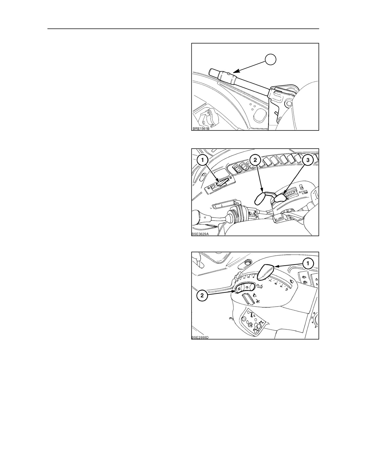
Raising and Lowering the Hitch (All Types)
With Mechanical Draft Control
Move both position (2) and draft (3) control levers
fully rearwards until the 3-point lift is supporting the
weight of the hitch.
To unlock the hitch, slide the collar (1) upwards
Figure 184, and then pull up and hold the release
handle. Lower the hitch to the ground by means of
the position control lever.
185
With Electronic Draft Control
Rotate the thumb wheel (2) fully forward to position
10. Move the Position Control lever
(1) fully
rearwards until the 3-point lift is supporting the weight
of the hitch.
To unlock the hitch, slide the collar (1) upwards
Figure 184, and then pull up and hold the release
handle. Lower the hitch to the ground by means of
the position control lever.
186
3--108
SECTION 3 -- FIELD OPERATION
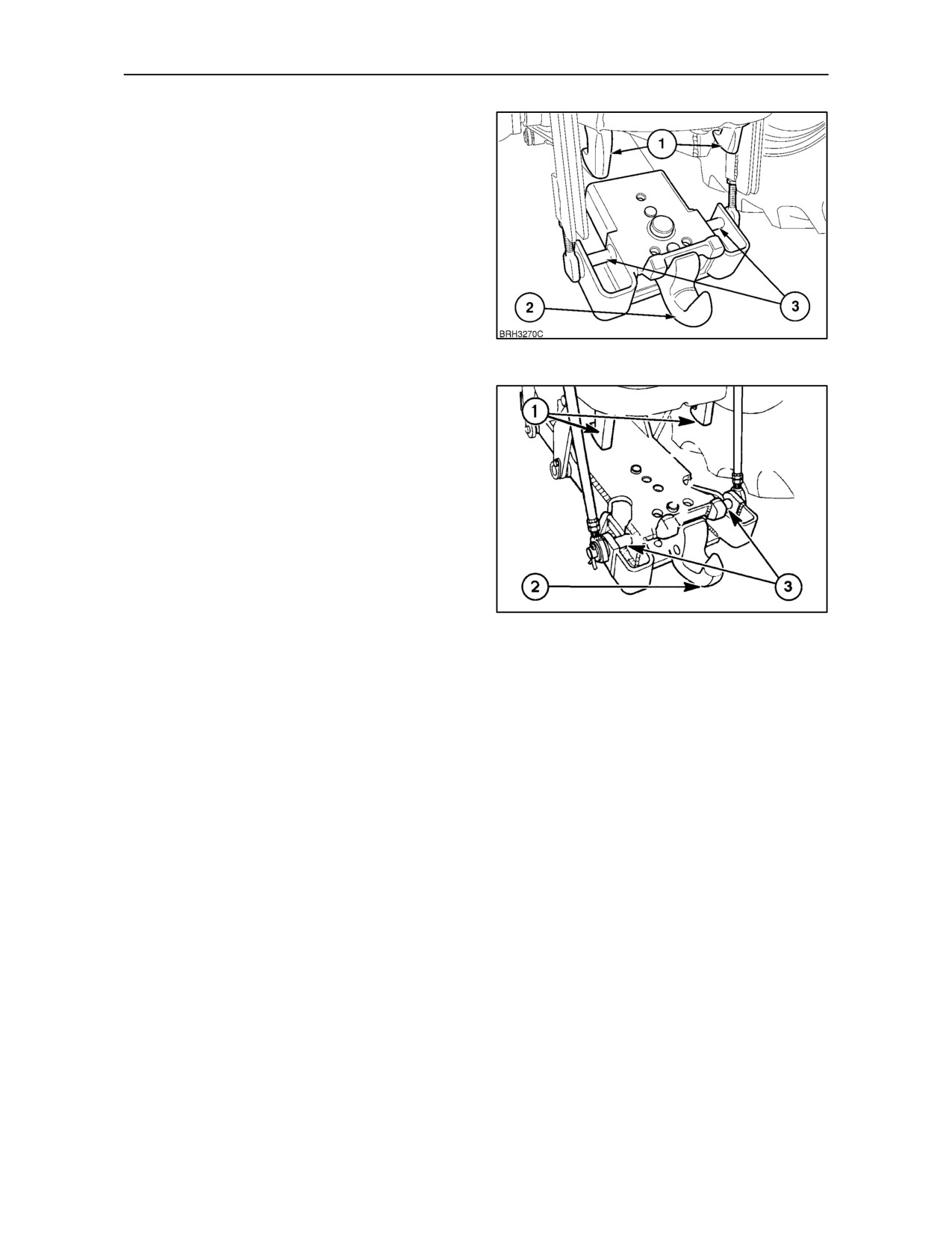
Position the tractor so that the hitch hook (2) is
beneath the eye of the implement drawbar and, using
the position control lever, raise the hitch slowly until
an audible click indicates the locking latches (1) have
engaged the cross tubes (3).
IMPORTANT: Ensure that the height limit control is
at the maximum height position. Failure to observe
this may result in the hitch failing to latch correctly.
Push the position control lever forward so that the
weight of the pick--up hitch (and attached implement)
is supported by the locking latches.
187
NOTE: The maximum static downward load on the
hitch hook (all types) must not exceed 3000 kg (6610
lb.)
When towing equipment exerting high static
downward forces, such as two-wheeled trailers, etc.,
always use the close-coupled drawbar position.
Alternatively, change to the hitch hook mode.
IMPORTANT: When supporting equipment on the
drawbar or pick-up hitch ensure that the total weight
on the rear axle does not exceed the maximum static
downward load or the rear tyre load capacity,
whichever is the lower (See Rear Tyre Pressures and
188
Loads at the end of Section 3).
3--109
SECTION 3 -- FIELD OPERATION
Drop Down Pick--Up Hitch (where fitted)
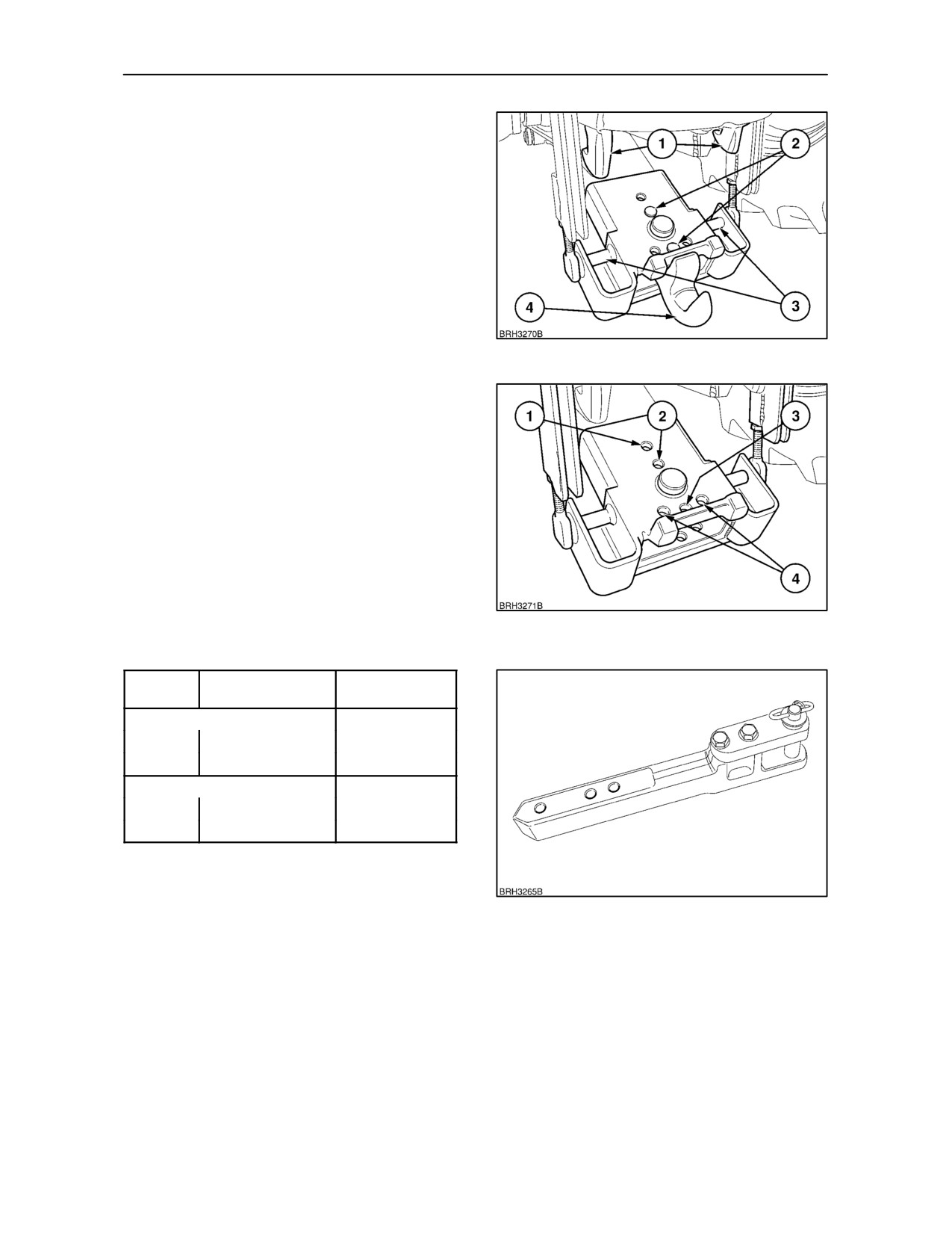
The hook on the drop down hitch is interchangeable
with the clevis drawbar.
To change from the hook to drawbar, lower the
pick--up hitch, extract the two securing pins
(2)
Figure 189 and withdraw the hook assembly.
Install the clevis drawbar assembly and secure with
the two pins.
IMPORTANT: Never raise or lower the pick--up hitch
when in the drawbar mode with a trailer attached.
189
There are three holes in the drawbar support. When
using holes (1), (2), and (3) in conjunction with the
holes in the clevis drawbar, a choice of
implement/drawbar hitch points, relative to the end
of the P.T.O. shaft may be achieved. See Figure 190
and the table below for hitch point position and
maximum permitted static downward load on the
drawbar:
The two additional holes (4), are provided in the
hanger for the rear securing pin so the drawbar may
be offset to the left or right of the centre line.
The drawbar, Figure 191, may be inverted to vary the
190
height of the drawbar/implement hitch point.
Hole (see
P.T.O Shaft to
Maximum Static
Fig. 190 )
Drawbar Hitch Point
Downward Load
Drawbar clevis uppermost
1
356 mm (14 in.)
1650 kg (3630 lb.)
2
406 mm (16 in.)
1500 kg (3300 lb.)
Drawbar clevis underneath
1
356 mm (14 in.)
1650 kg (3630 lb.)
2
406 mm (16 in.)
1500 kg (3300 lb.)
191
3--110
SECTION 3 -- FIELD OPERATION
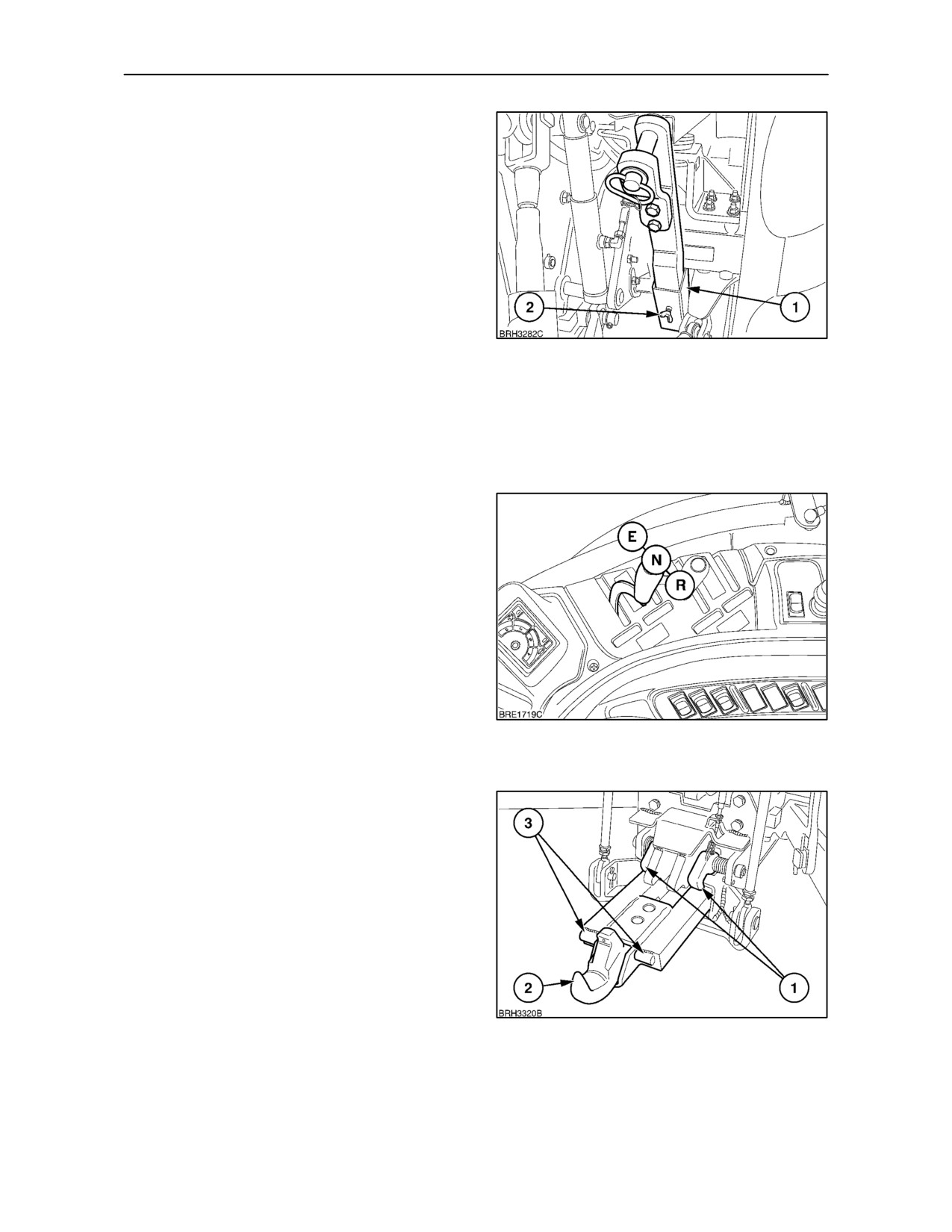
When not in use, the hook or clevis drawbar may be
stored in the bracket (1), attached to the rear axle.
Ensure the clamp screw (2), is fully tightened to
retain the drawbar in the bracket.
192
Extendible Pick--Up Hitch (where fitted)
The extendible pick--up hitch can be hydraulically
extended to aid visibility when attaching towed
equipment.
Operated through one of the rear remote valves, the
hitch is extended or retracted using the remote valve
lever. The hoses should be connected in such a way
that moving the remote valve lever to E (Extend) will
extend the hitch, moving the lever to R (Retract) will
retract the hitch.
NOTE: The illustration shows hitch operation
through remote valve number I, however, it may be
operated using an alternative valve where required.
Lower the hitch until it is clear of the locking latches
and then extend the hook or clevis rearwards by
moving the remote valve lever to (E). With the
193
drawbar extended continue to lower the hitch until it
is just above the ground.
Position the tractor so that the hitch hook (2) is
beneath the eye of the implement drawbar and, using
the position control lever, raise the hitch until the
implement drawbar is just clear of the ground.
Fully retract the pick--up hitch by moving the remote
valve lever to (R). To assist in retracting the hitch
release the tractor brakes to allow movement of the
tractor towards the implement. Re--apply the
handbrake before leaving the tractor seat.
With the hitch in the fully retracted position raise it
slowly until an audible click indicates the locking
latches (1) have engaged the cross tubes (3).
194
3--111
SECTION 3 -- FIELD OPERATION
IMPORTANT: The hitch must be fully retracted
before it will lock correctly. Always ensure the hitch
is locked before operating the tractor.
NOTE: The maximum static downward load on the
hitch hook must not exceed 3000 kg (6610 lb.)
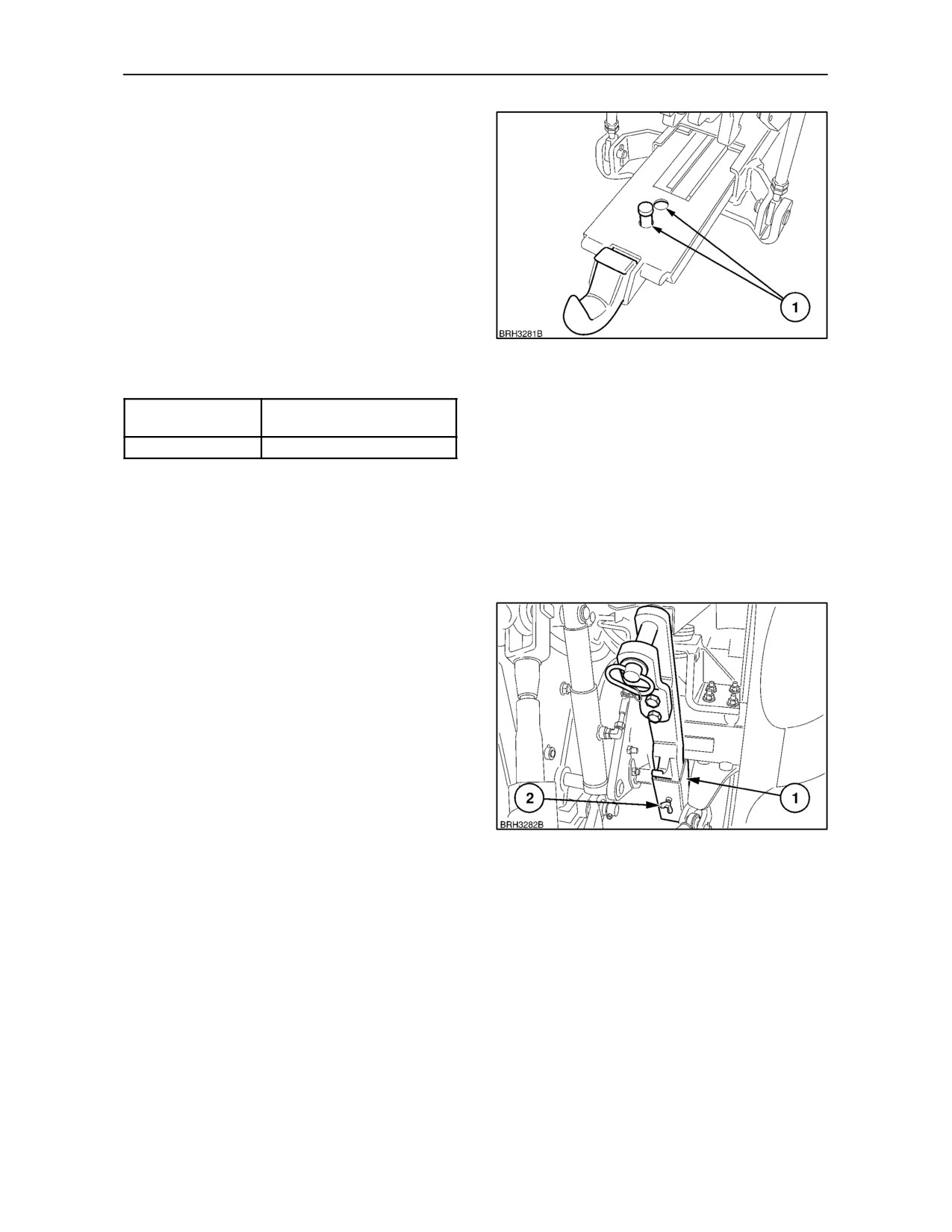
To change from the hook to drawbar, lower the
pick--up hitch, extract the two securing pins (1) and
withdraw the hook assembly.
Install the clevis drawbar assembly and secure with
the two pins.
195
Maximum Permissible Clevis Load
P.T.O Shaft to
Maximum Static
Drawbar Hitch Point
Downward Load
406 mm (16 in.)
1500 kg (3300 lb.)
IMPORTANT: When supporting equipment on the
drawbar or pick-up hitch ensure that the total weight
on the rear axle does not exceed the maximum static
downward load or the rear tyre load capacity,
whichever is the lower (See Rear Tyre Pressures and
Loads at the end of Section 3).
When not in use, the hook or clevis drawbar may be
stored in the bracket (1), attached to the rear axle.
Ensure the clamp screw (2), is fully tightened to
retain the drawbar in the bracket.
If the hydraulic hitch pressure lines are disconnected
from the remote valve, ensure the male couplings
are protected from contamination and the pressure
lines secured to the tractor to avoid possible
damage.
196
3--112
SECTION 3 -- FIELD OPERATION
TRAILER BRAKES
(where fitted)
Hydraulic Trailer Brakes (except Italy)
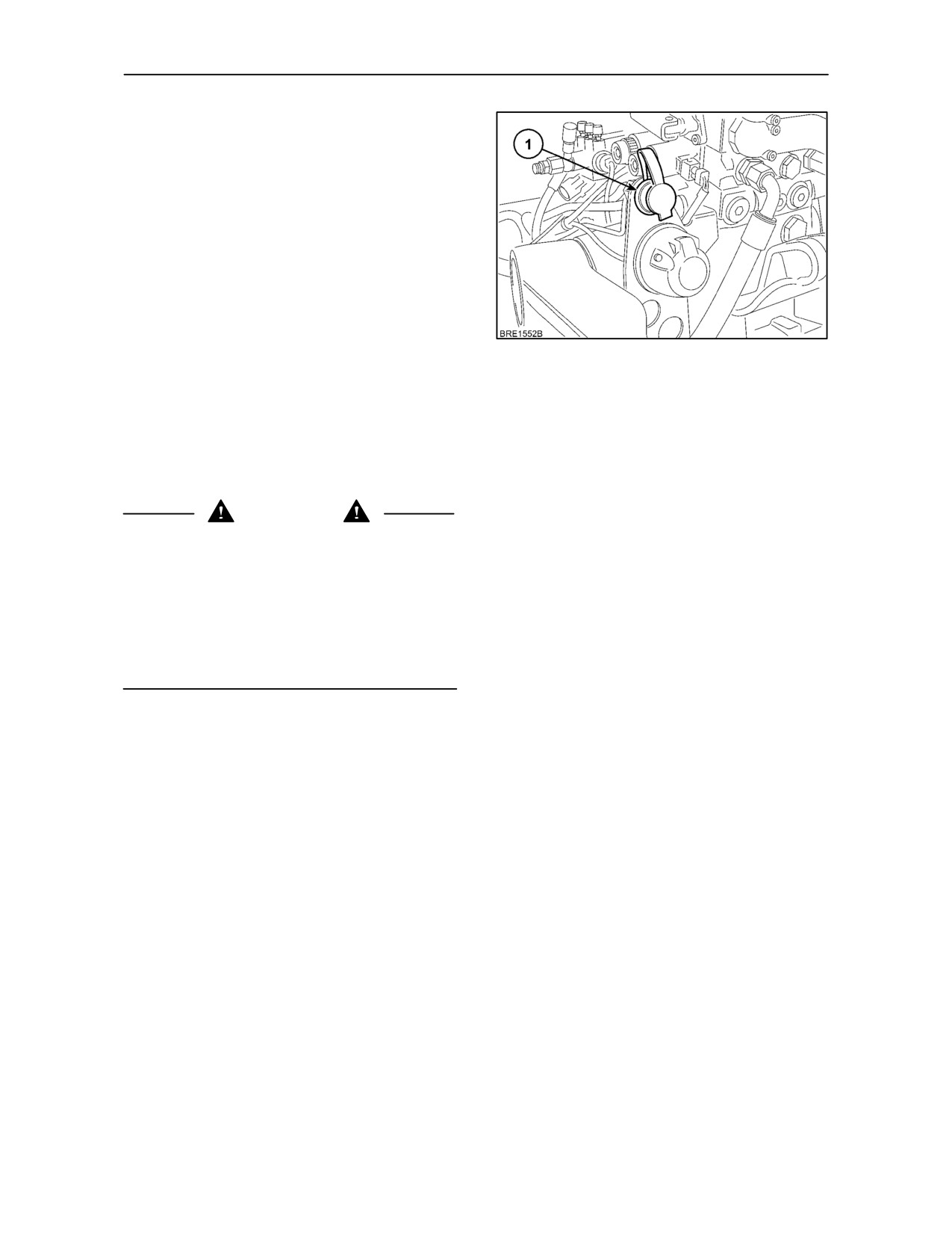
Hydraulic trailer brakes may be connected into the
hydraulic system via a quick--release coupling (1) at
the rear of the tractor.
NOTE: The position of the trailer brake coupling may
vary slightly from that shown, dependent upon the
type of remote control valves installed.
197
If thetrailerbrakehoseisconnectedinto thecoupling
the trailer brakes will be automatically applied when
the footbrakes are used to stop the tractor.
IMPORTANT: It is essential that the brake pedals are
locked together to ensure correct operation of trailer
brakes, balanced operation of the tractor brakes and
four wheel braking (four wheel drive tractors only).
WARNING
With the tractor engine off, hydraulic pressure cannot
be applied to the trailer braking system. When
parking the tractor/trailer combination apply the
tractor and trailer parking brakes while the engine is
still running. With the footbrakes locked together
apply the parking brake, stop the engine and
immediately block the wheels. Always lock the brake
pedals together when a hydraulically braked trailer is
attached to the tractor.
NOTE: Always keep the dust--cap in place when the
trailer brake coupling is not in use. It is a legal
requirement in most countries that trailer brakes may
only be connected to the tractor coupling by means
of a compatible female coupling.
3--113
SECTION 3 -- FIELD OPERATION
Hydraulic Trailer Brakes
(Italy only)
The hydraulic trailer braking system on tractors for
the Italian market function in a slightly different way
to the universal system previously described.
If thetrailerbrakehoseisconnectedinto thecoupling
the trailer brakes will be automatically applied when
the footbrakes are used to stop the tractor or when
the tractor handbrake is applied when the engine is
running. When the engine is switched off, the trailer
brakes will remain applied.
198
IMPORTANT: It is essential that the brake pedals are
locked together to ensure correct operation of trailer
brakes, balanced operation of the tractor brakes and
four wheel braking (four wheel drive tractors only).
To release hydraulic pressure and free the trailer
brakes, start the engine, depress both brake pedals
and release the tractor handbrake.
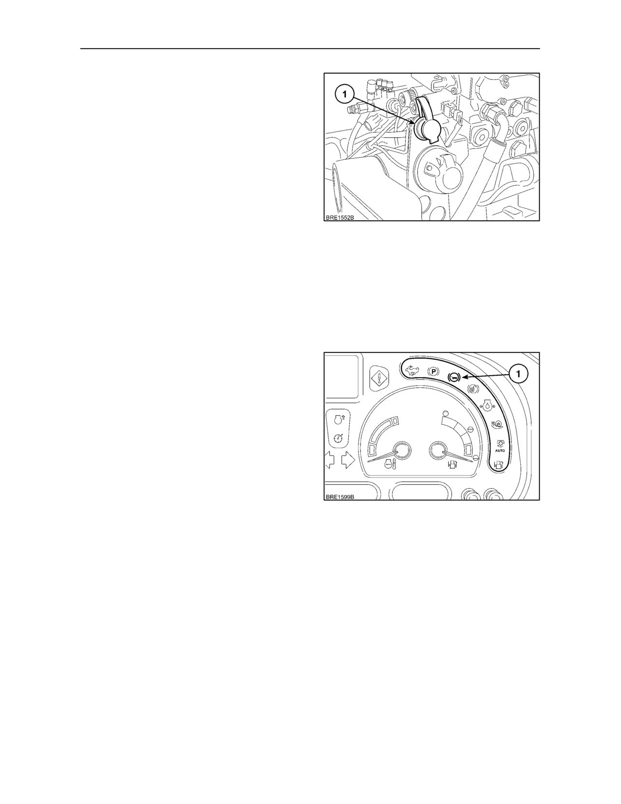
NOTE: The light (1), on the instrument panel will
flash, accompanied by critical alarm, to indicate that
hydraulic oil pressure to the trailer brake circuit is low.
Stop the engine and investigate the cause.
ATTENTION: Should the trailer brake warning light
commence to flash, the trailer brakes will apply
automatically.
NOTE: Always keep the dust--cap in place when the
trailer brake coupling is not in use. It is a legal
requirement in most countries that trailer brakes may
only be connected to the tractor coupling by means
of a compatible female coupling.
199
3--114
SECTION 3 -- FIELD OPERATION
AIR--OPERATED TRAILER BRAKING SYSTEMS
Air--Operated Trailer Brakes
(except Italy)
WARNING
Single line trailer braking systems are designed for
use up to a maximum speed of 25 km/h (15 MPH).
Tractor/trailer combinations with dual line braking
systems may be used at a higher speed but must at
all times comply with local legal requirements. Gross
train weight, i.e., tractor plus trailer(s) and/or
individual trailer weight must not exceed that laid
down in local regulations governing the use of
trailers.
The following text covers operation of the air-
operated trailer braking systems that may be
installed as an alternative to hydraulically-actuated
trailer brakes.
The system consists of an engine-driven air
compressor, one or two air reservoirs, dependent
upon type of system installed, a pressure gauge,
control valves, two or three couplers and related
pipework.
A filter/dryer unit in the braking system extracts
moisture from the pressurised air helping to avoid
componenets in the implement braking system from
freezing in low temperatures. Any moisture collected
is automatically exhausted through the system
unload valve.
The couplers installed at the back of the tractor may
be connected to single or dual line trailer braking
systems. Either or both types may be installed. The
air lines connected to the couplers are colour-coded
black, red and yellow. The black line is used for a
single line system, the red and yellow lines are used
for dual line systems.
IMPORTANT: The trailer brakes will only operate
when both tractor brake pedals are applied.
Therefore, always lock the brake pedals together
when a trailer is attached to the tractor.
NOTE: The tractor handbrake is connected to the
main control valve. Whenever the handbrake is
applied, the trailer brakes are activated.
3--115
SECTION 3 -- FIELD OPERATION
Operation
When starting the engine with a trailer connected into
the tractor air brake system, chock the wheels and
release the parking brake and footbrakes. The
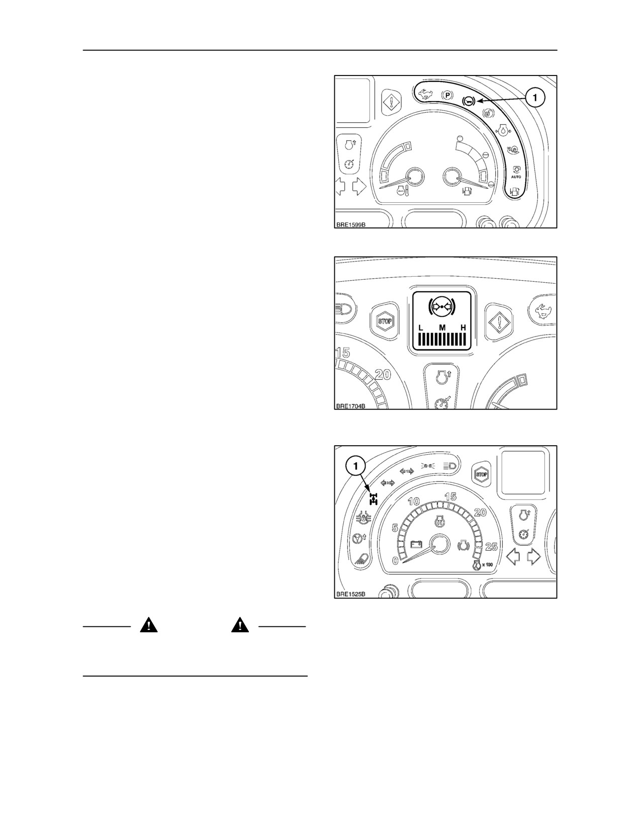
warning light (1) Figure 200, will illuminate until air
pressure builds up to 4.5 -- 5.5 bar.
The pressure will continue to rise, as indicated by the
air pressure bargraph in the Dot Matrix Display,
Figure 201. To select the air pressure bargraph, use
the CAL/SEL switch or, where fitted, the enhanced
keypad.
200
The air tank(s) should reach operating pressure
within 3 minutes of start--up but may take longer,
dependent upon the size of the trailer brake
reservoir(s).
Once required pressure has been reached a loud
‘pop’ will be heard, signifying that the unload valve
has opened to allow excess pressure to escape to
atmosphere.
IMPORTANT: Apply the footbrakes several times,
ensuring that the pressure, as indicated by the
gauge, drops as the brakes are applied and rises
again when they are released. Never drive the tractor
201
with the trailer brake warning light on.
IMPORTANT: When the footbrakes are applied ,with
the handbrake off, ensure that the front wheel drive
indicator light (1) Figure 202 illuminates and that all
stop lights are functional.
IMPORTANT: Various types of trailer braking
systems are available. Check the trailer
manufacturers’ instruction manual before making
connections to the tractor air brake system.
Clean the trailer and tractor connectors before
coupling up the hose(s). Ensure that connections are
secure. Check the trailer brakes regularly to ensure
that they are functioning correctly.
202
CAUTION
Do not over use the brakes on steep down hill
gradients. Use the same gear going down hill as you
would use for going up the same hill.
3--116
SECTION 3 -- FIELD OPERATION
Dual Line System
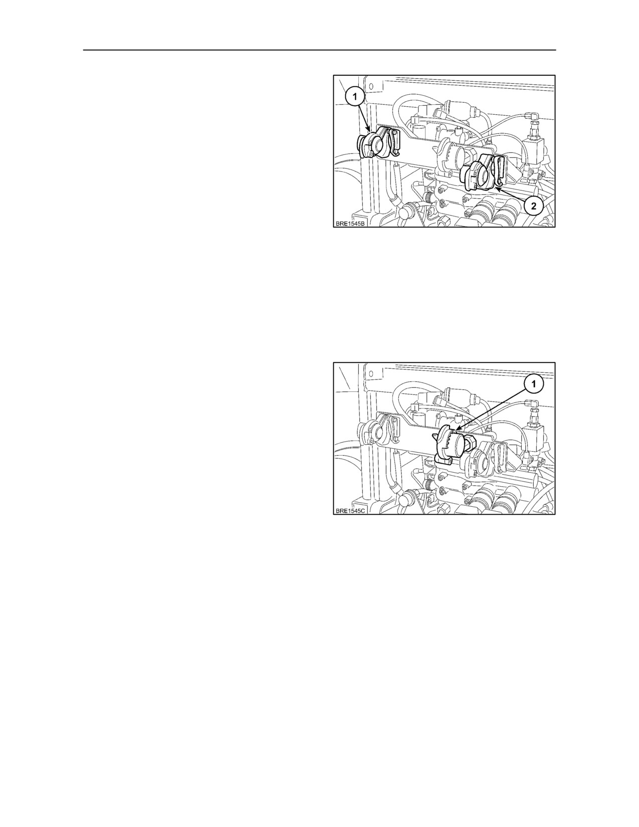
For a trailer with a dual line braking system, connect
the supply line hose to the red coupler (1) and the
control line hose to the yellow coupler (2).
IMPORTANT: The dual line system will only operate
if both the red and yellow lines are connected.
Red line (brake supply line) -- (1): Air is supplied to
the red coupler at full system pressure. This is the
brake supply line and charges the reservoir(s) on the
trailer. If the trailer braking system is disconnected
from the tractor for any reason, the air pressure will
203
fall to zero and the trailer brakes will be applied.
Yellow line (control line)
--
(2): As the tractor
brakes are applied, increasing air pressure is
supplied, via the yellow coupler, to the control valve
on the trailer until full system pressure is generated.
Application of the trailer brakes is proportional to the
pressure applied to the tractor brake pedals.
Single Line System
If the trailer has a single line system an additional
coupler is supplied. Connect the hose to the black
coupler (1) Figure 204.
A pressure of 5.5 bar is available at the coupler at all
times when the tractor brake pedals and parking
brake are released. Application of the tractor brakes
causes the pressure to drop to zero allowing the
trailer brakes to be applied.
204
3--117
SECTION 3 -- FIELD OPERATION
Air--Operated Trailer Brakes
(Italy Only)
This system operates in a similar manner to the dual
line system, previously described, except that a
combined dual coupler is utilised. Please read all the
previous text relating to pneumatic trailer brakes plus
the following:
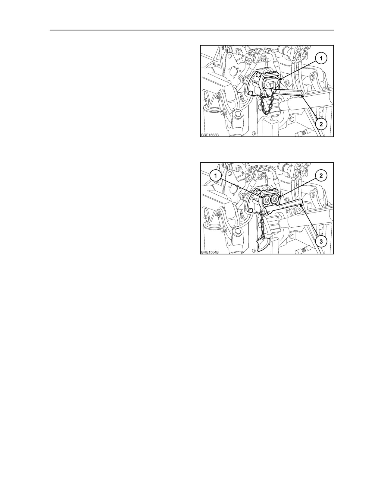
The coupler is protected by a metal cover. To remove
the cover, press the handle (2) down. The handle is
held in position by a stiff spring and some pressure
is required to move it down to release the cover (1).
205
Connections
The lines to the couplers are colour-coded for ease
of use. The supply line to the left-hand coupler (1) is
red and the control line to the right-hand coupler (2)
is yellow. The trailer hoses will have a male dual
coupler. Press down the handle (3) and insert the
trailer coupler. When the handle is released, it will
lock the trailer and tractor couplers together.
206
3--118
SECTION 3 -- FIELD OPERATION
Tractor/Trailer Brake Bias Control
When the tractor leaves the factory, this control is set
to allow maximum available braking effort to the
trailer. Under most conditions, the control will remain
in this position and will give well balanced braking.
Occasionally, with some trailers this setting may
provide a greater braking bias to the trailer than is
ideal. In this case the braking force to the trailer may
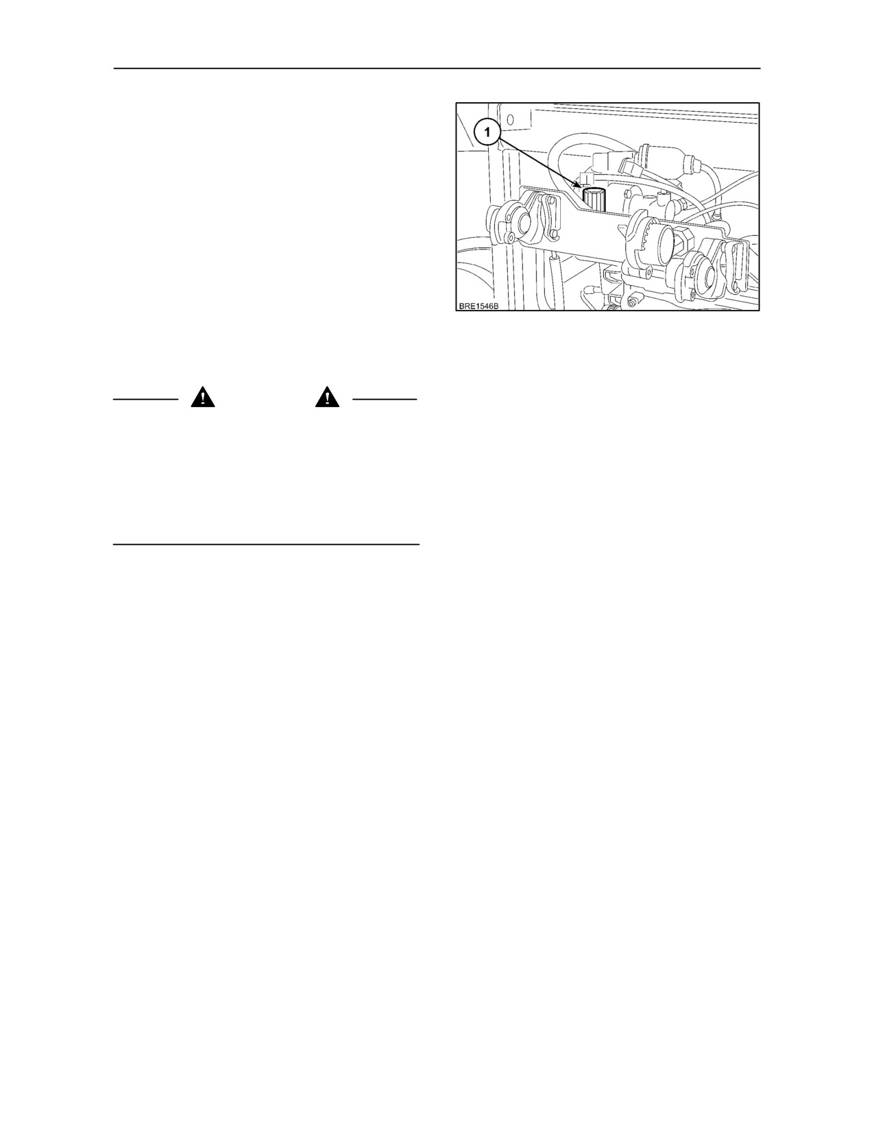
be reduced slightly by turning the adjuster (1) in an
anti--clockwise direction.
To turn the valve, it is first necessary to pull the knob
207
out. After adjustment, push the knob in to lock the
setting. The adjuster must be reset to the fully
clockwise position when a different trailer is used.
WARNING
The brake balance adjustment is extremely sensitive
and should not be rotated more than one half turn
before testing with the attached trailer fully loaded. If
further adjustments are required, they should be
carried out following the same procedure. Failure to
do this may result in an imbalance between tractor
and trailer braking forces if the valve is rotated too far
in the anti--clockwise direction.
3--119
SECTION 3 -- FIELD OPERATION
EQUIPMENT MOUNTING POINTS
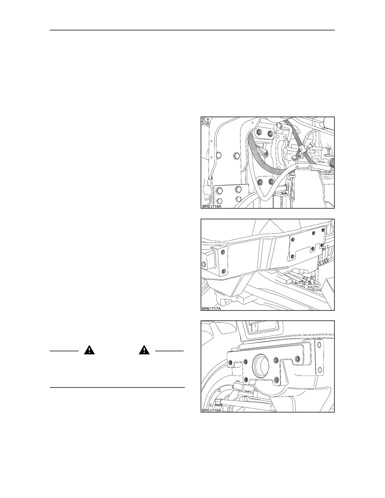
Your tractor is provided with a number of threaded
holes for the purpose of attaching optional
equipment. All threaded holes will accept M20 x 2.5
fixings. The depth of the holes will vary depending on
location, therefore it is important the hole is checked
before inserting any mounting bolt or stud to avoid
damage to the thread or metal casting.
Transmission Housing
Figure 208
shows the mounting points on the
left-hand side of the tractor. There are matching
threaded holes on the right-hand side.
NOTE: Care should be taken when using holes in the
transmission housing when mounting equipment to
avoid any conflict with the cab or components below
the tractor.
IMPORTANT: Do not attach any equipment or
brackets to the cab mounting points
208
Front Axle Support Casting
Depending on tractor specification, the number of
holes in the side of the axle support casting may vary.
NOTE: Consult the hardware torque chart in Section
8
for correct torque settings when attaching
equipment to the mounting points. Re--check the
torque settings after one hour of operation and on a
daily basis thereafter.
209
NOTE: If you have front end weights on your tractor
then these holes will have already been utilised for
the weight carrier.
CAUTION
When attaching equipment to the mounting points,
adjust the tyre pressures to compensate for the
additional weight. Ensure the maximum axle loads
for the tractor are not exceeded, see page 3--132.
210
3--120
SECTION 3 -- FIELD OPERATION
FRONT WHEEL TRACK ADJUSTMENT
Standard Axle
(two wheel drive)
(6 stud fixing -- where fitted)
Securing Bolt Locations
Track Width
WARNING
Refer to Figure 211
7.50 x 16 Tyres
Your tractor is produced with lights that meet lighting
A -- C
1465 mm (57.6 in.)
regulations when operating or travelling on the public
highway. If the wheel track setting is adjusted beyond
B -- D
1567 mm (61.6 in.)
the initial factory position then you may be required
C -- E
1669 mm (65.7 in.)
to reposition the lights or fit auxiliary lighting to
D -- F
1770 mm (69.6 in.)
comply with legal requirements. Before travelling on
the highway, ensure that the overall tractor width
E -- G
1872 mm (73.7 in.)
does not exceed the maximum permitted in your
F -- H
1974 mm (77.7 in.)
country.
G -- J
2076 mm (81.7 in.)
H -- K
2177 mm (85.7 in.)
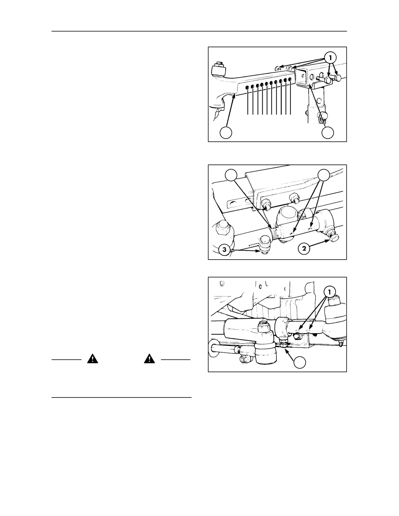
The front axle consists of a hollow centre beam with
a telescopic section at each end. Adjustment of the
Note: Reversing the wheels will increase track width by
front wheel track width is effected by extending both
134.4mm (5.29”)
ends of the axle equally. A number of holes at
approximately 50 mm (2 in.) intervals are provided in
Heavy Duty Axle
the telescopic sections for track adjustment
(8 stud fixing -- where fitted)
purposes.
Securing Bolt Locations
Track Width
Refer to Figure 211
10.00 x 16 Tyres
NOTE: The track width is the distance between the
centre of each tyre, measured at ground level.
A -- C
1580 mm (62.2 in.)
B -- D
1667 mm (65.6 in.)
NOTE: The track settings shown are approximate.
C -- E
1754 mm (69.0 in.)
The front wheel discs are dished. The track settings
in the tables above are with the convex side of the
D -- F
1841 mm (72.4 in.)
discs facing outwards. If the front wheels are
E -- G
1928 mm (75.9 in.)
reversed on the hubs the track settings shown in the
tableswillbeincreasedbyapproximately100mm
F -- H
2016 mm (79.3 in.)
(4 in.).
G -- J
2103 mm (82.7 in.)
H -- K
2190 mm (86.2 in.)
To extend the axle, apply the handbrake and place
blocks at the front and rear of the rear wheels. Jack
Note: Reversing the wheels will increase track width by
up the front axle and place on axle stands. Remove
108.2mm (4.25”)
the securing bolts
(1) Figure 211, securing the
right-hand telescopic section to the centre beam.
Wide Axle (North America only)
(8 stud fixing -- where fitted)
Repeat on the left-hand side of the axle.
Securing Bolt Locations
Track Width
Refer to Figure 211
10.00 x 16 Tyres
Loosen the locknuts and remove the locating bolts
(2) Figures 212 and 213, from both ends of the track
A -- C
1782 mm (70.1 in.)
control rod behind the axle.
B -- D
1869 mm (73.5 in.)
C -- E
1956 mm (77.0 in.)
Figure 212 shows the left-hand end of the track
control rod. Figure 213 shows the right-hand end.
D -- F
2043 mm (80.4 in.)
The extendible sections are drilled at 50 mm (2 in.)
E -- G
2130 mm (83.8 in.)
intervals and two locating bolts pass through the tube
F -- H
2218 mm (87.3 in.)
and into the solid sections to lock the track rod
assembly at the required length. Additionally, the
G -- J
2305 mm (90.7 in.)
left-hand end of the solid section is threaded to
H -- K
2392 mm (94.1 in.)
provide fine adjustment.
Note: Reversing the wheels will increase track width by
108.2mm (4.25”)
3--121
SECTION 3 -- FIELD OPERATION
Reset the left and right-hand axle telescopic
sections, passing the securing bolts through the
centre beam and telescopic sections, as indicated in
Figure 211 and the track setting tables.
Position both front wheels straight ahead and install
the locating bolts (2) Figures 212 and 213, in the
appropriate drilling (1) at each end of the track control
rod.
ABCDEFGHJK
Tighten the nuts on the axle extension securing bolts
to 400 Nm (300 lbf.ft.). Tighten the locating bolts (2)
3
2
Figures 212 and 213, to 150 Nm (110 lbf. ft.) and
their locknuts to 75 Nm (55 lbf. ft.). Re-check all
211
torque settings after 50 hours of operation.
Front Wheel Alignment
4
1
After resetting the track width, the front wheel toe-in
may require adjustment. For correct operation, the
front wheels should be parallel or toe in slightly.
Measure the distance between the wheel rims at hub
height at the front of the wheels. Rotate both front
wheels 180° and check the measurements again,
this time at the rear of the wheels. This will eliminate
wheel rim run-out errors. The correct toe-in setting is
0 -- 13 mm (0 -- 0.5 in.), i.e. the measurement taken
at the front of the rims should be the same as the rear
or be smaller by up to 13 mm (0.5 in.).
212
Should it be necessary to adjust the front wheel
toe--in, proceed as follows:
Remove the locating bolt (2) from the left--hand end
of the track rod, slacken the clamp bolt (3) and turn
the threaded section of the track rod (4) in or out until
the toe-in is correct when the locating bolt is
re-inserted. Tighten the clamp bolt to 100 Nm (75
lbf.ft.), the locating bolts to 150 Nm (110 lbf. ft.) and
their locknuts to 75 Nm (55 lbf. ft.).
WARNING
2
Owners should ensure that all steering components
are maintained in a reliable and satisfactory
213
condition to ensure safe operation and comply with
legal requirements.
3--122
SECTION 3 -- FIELD OPERATION
FRONT WHEEL TRACK ADJUSTMENT
(four wheel drive)
Front Axle with Variable Track Front Wheels
A
The sectioned drawings illustrate the wheel rim and
disc positions relative to the hub at various track
settings. The track widths available are as follows:
Track settings with 24” and 28” front wheels
B
Position
Track Width
(Figure 214)
A
1566 mm (61.6 in.)
B
1662 mm (65.4 in.)
C
1766 mm (69.5 in.)
D
1862 mm (73.3 in.)
C
E
1966 mm (77.4 in.)
F
2062 mm (81.1 in.)
G
2166 mm (85.2 in.)
H
2262 mm (89.0 in.)
D
The track widths in the above table are based on a
tractor fitted with a Standard 4WD front axle.
With front axle Suspension, add 18mm (0.7 in.).
With SuperSteer front axle, add 18mm (0.7 in.).
NOTE: The track widths in the table above are
E
nominal and may vary by up to 25 mm (1 in.)
dependent upon tyre size.
IMPORTANT: With optional Dynamic fenders fitted,
narrower track settings may not be attainable due to
insufficient clearance between the tyre or rim and
any part of the fender or attaching hardware.
F
IMPORTANT: If your tractor is equipped with front
fenders, ensure there is adequate clearance
between fender and wheel under all operating
conditions. With the smaller track settings a foul
condition may occur between the tyre or fender and
the tractor when the wheels are turned to the full lock
G
position particularly when the axle is fully articulated.
To avoid this condition, adjust the fenders and/or
steering stops.
H
214
3--123
SECTION 3 -- FIELD OPERATION
With Non Adjustable Front Wheels
Tractors equipped with non adjustable front wheels
offer a choice of two track settings. To alter the track
width, interchange both front wheels to provide a
A
narrow (A) or wide (B) track setting as required.
NOTE: Tractors with a
50
K/mh
(31
MPH)
transmission will be fitted with non adjustable front
wheels).
NOTE: When interchanging left and right--hand
wheel assemblies, ensure the “V” of the tread at the
B
top of the tyre remains pointing in the direction of
forward travel.
215
Track settings with 24” and 28” Wheels
4WD Front axle type
Position
Track Setting
Standard -- min. setting
A
1854 mm (73.0 in.)
Standard -- max. setting
B
2080 mm (81.9 in)
Suspended -- min. setting
A
1821
mm (71.7 in.)
Suspended -- max. setting
B
1978
mm (77.9 in.)
Supersteer -- min. setting
A
1821
mm (71.7 in.)
Supersteer -- max. setting
B
1978
mm (77.9 in.)
NOTE: The track widths in the table above are
nominal and may vary by up to 28 mm (1.1 in.)
dependent upon wheel rim offset.
REFITTING THE FRONT WHEELS
When refitting or adjusting a wheel, tighten the bolts
to the following torques then re-check after 50 hours
of operation and, thereafter as required.
Disc to hub nuts
294 Nm (217 lbf.ft.)
Disc to rim nuts
250 Nm (184 lbf.ft.)
(where applicable)
WARNING
Never operate the tractor with a loose wheel rim or
disc. Always tighten nuts to the specified torque and
at the recommended intervals. Owners should
ensure that all steering components are maintained
in a reliable and satisfactory condition to ensure safe
operation and comply with legal requirements.
3--124
SECTION 3 -- FIELD OPERATION
FRONT WHEEL ALIGNMENT
1
After resetting the track width, the front wheel
alignment may require adjustment. For correct
operation, the front wheels should be parallel.
Measure the distance between the wheel rims at hub
height at the front of the wheels. Rotate both front
wheels 180° and check the measurements again,
this time at the rear of the wheels. This will eliminate
wheel rim run-out errors. The correct setting is 0+/--
3 mm (0 -- 0.12 in.)
3
2
Should it be necessary to adjust the front wheel
TA43
alignment, proceed as follows:
216
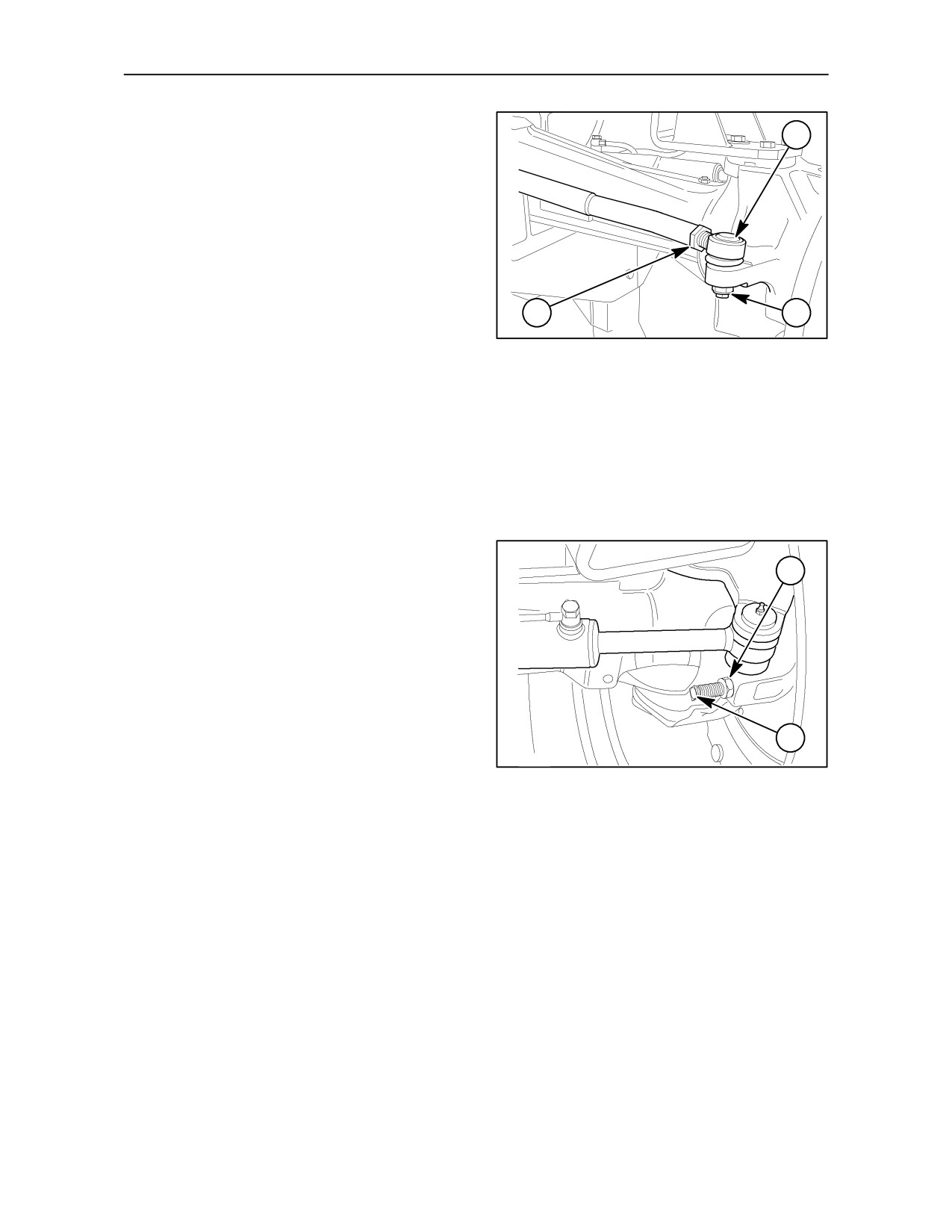
Remove and discard the self-locking nut (2), on the
left-hand end of the track control rod (1) and extract
the track rod end. Loosen the lock nut (3) and screw
the track rod end into or out of the track rod to shorten
or lengthen the assembly, as required. Re-insert the
track rod end and, when the setting is correct, secure
with a new self-locking nut. Tighten the self-locking
nut to 100 Nm (74 lbf. ft.) and the lock nut to 180 Nm
(133 lbf. ft.).
STEERING STOPS
1
Two steering stops are incorporated in the axle, one
at each end. The stops are adjustable and should be
set to provide a minimum clearance of 20 mm (0.75
in.) between the tyres and any part of the tractor on
full left and right lock with the axle fully articulated.
To adjust, slacken the locknut and turn the stop bolt
anti-clockwise to reduce the steering angle of the
wheels or clockwise to increase the steering angle.
Tighten the locknut to 150 Nm (110 lbf. ft.).
2
TA41
217
3--125
SECTION 3 -- FIELD OPERATION
FRONT AXLE OSCILLATION STOPS
(where fitted)
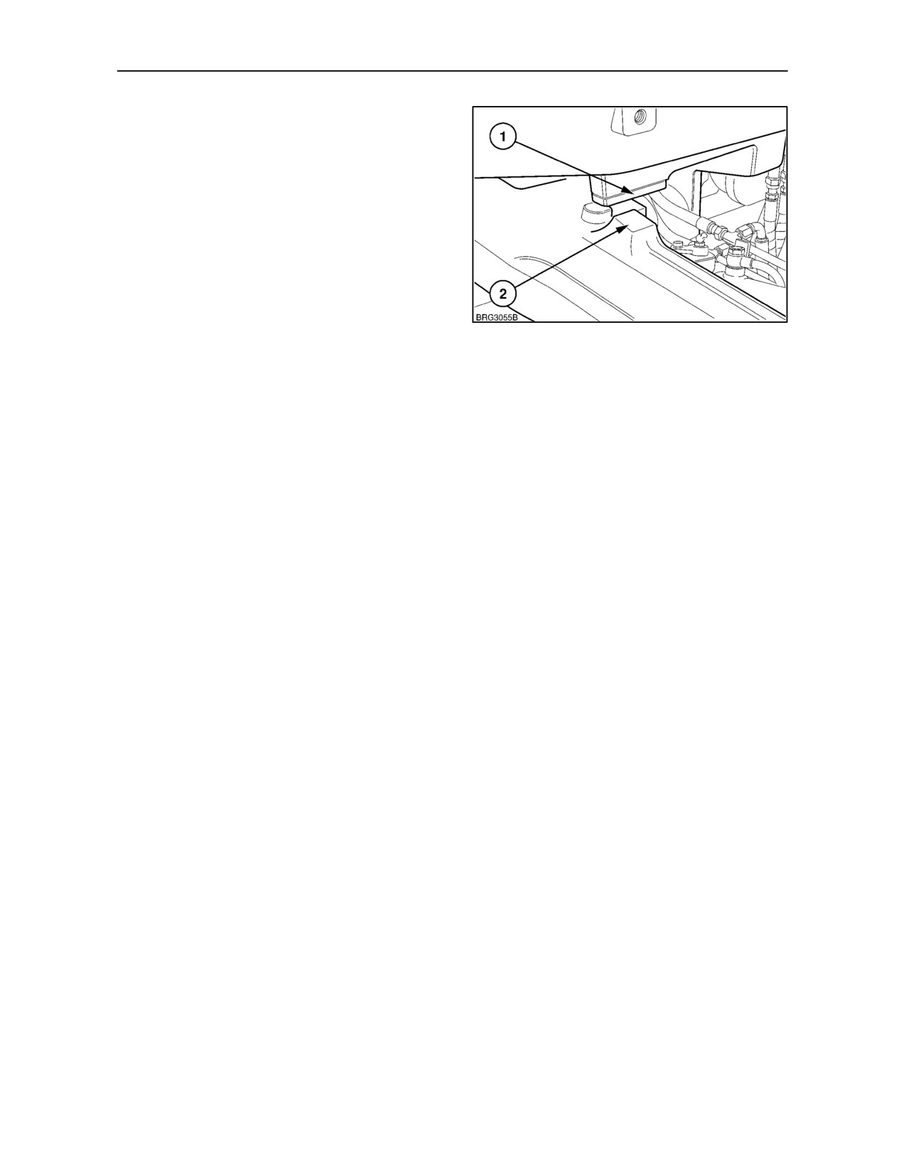
Where fitted, the axle oscillation stops are installed
one each side of the axle. Each stop consists of a
plate (1), secured to the underside of the front axle
support by two flush fitting, socket head screws.
Oscillation of the axle causes the stop plate to
contact the projection (2) on the axle casing, so
preventing further movement. With the stop plates in
position, as shown, axle oscillation is 8°.
Extract the screws and remove the stop plates to
increase axle oscillation to 12°.
218
NOTE: If the oscillation stops are removed, ensure
that there is adequate clearance between the front
tyres and any part of the tractor with the axle fully
articulated.
3--126
SECTION 3 -- FIELD OPERATION
DYNAMIC FRONT FENDERS
(where fitted)
Two types of optional front fender are available, both
offering a full range of adjustment to suit varying tyre
sizes and track widths. The method of adjustment is
very similar for both, but the following text describes
the setting of the dynamic fender. Ensure all fixing
bolts are re--tightened after adjustment.
Dynamic fenders turn with the front wheels as the
tractor is steered. As the steering angle increases, a
spring centered pivot in the fender mount restricts
the turn angle of the fenders. This prevents
interference with the tractor hood or loader frame
while allowing the wheels to continue turning
beneath the fender. As a result, tighter turns can be
achieved that would not be possible with a
conventional fender, particularly at narrower track
settings.
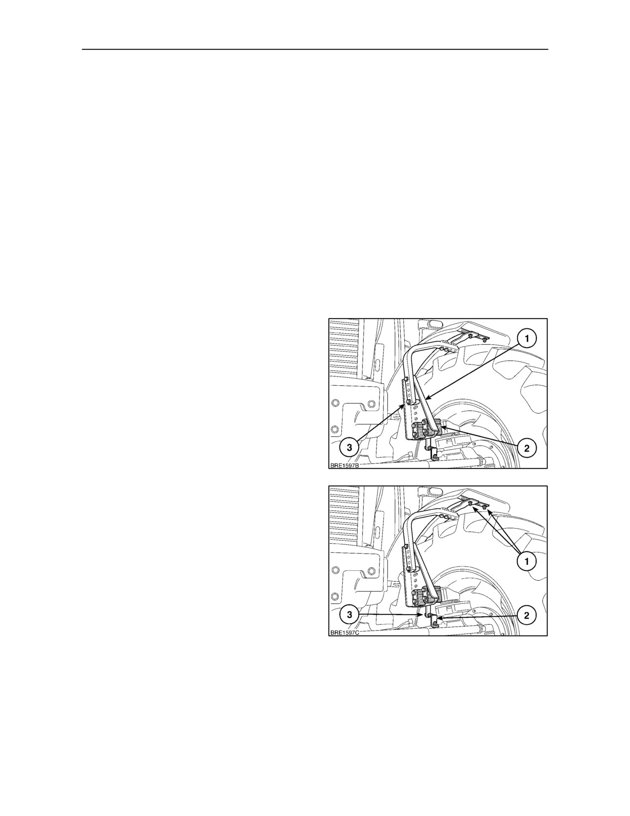
Lateral adjustment, fender support
A fender may be moved horizontally, towards or
away from the tractor, by relocating the metal shims
(2) either side of the fender support (1).
Vertical adjustment
The fender may be moved vertically by relocating the
bolts
(3) in the appropriate holes in the fender
support. A number of the holes are elongated
allowing the fender to be tilted forward or rearward.
Fender turn stop
219
An adjustable stop bolt (3), is fitted to both fender
support brackets. When turning, the bolt contacts a
fixed stop (2) on the axle housing restricting the angle
at which the fender will turn while allowing the wheels
to continue turning beneath the fender. The stops
may require adjusting if the track width or tyre size is
changed.
Lateral adjustment, fender
The support and bracket attachment points (1)
beneath the fender, provide further lateral
adjustment allowing the fender to be centered over
the tyre.
220
Narrow Track Settings
With certain options and/or tyre sizes, the smaller
track settings may not be attainable due to minimal
clearance between tyre or rim and any part of the
fender or attaching hardware.
3--127
SECTION 3 -- FIELD OPERATION
REAR WHEEL TRACK ADJUSTMENT
1
CAUTION
Your tractor is produced with lights that meet lighting
regulations when operating or travelling on the public
highway. If the wheel track setting is adjusted beyond
the initial factory position then you may be required
to reposition the lights or fit auxiliary lighting to
comply with legal requirements. Additionally, before
travelling on the highway, ensure that the overall
tractor width does not exceed the maximum
permitted in your country.
221
Rear wheel track adjustment is effected by changing
2
the wheel rim relative to the centre disc, the rim
and/or the disc relative to the axle hub or by
inter--changing the rear wheels.
CAUTION
Tractor wheels are very heavy. Handle with care and
ensure, when stored, that they cannot topple and
cause injury.
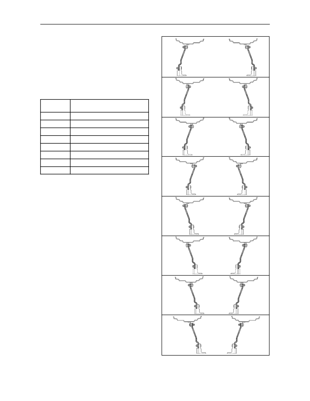
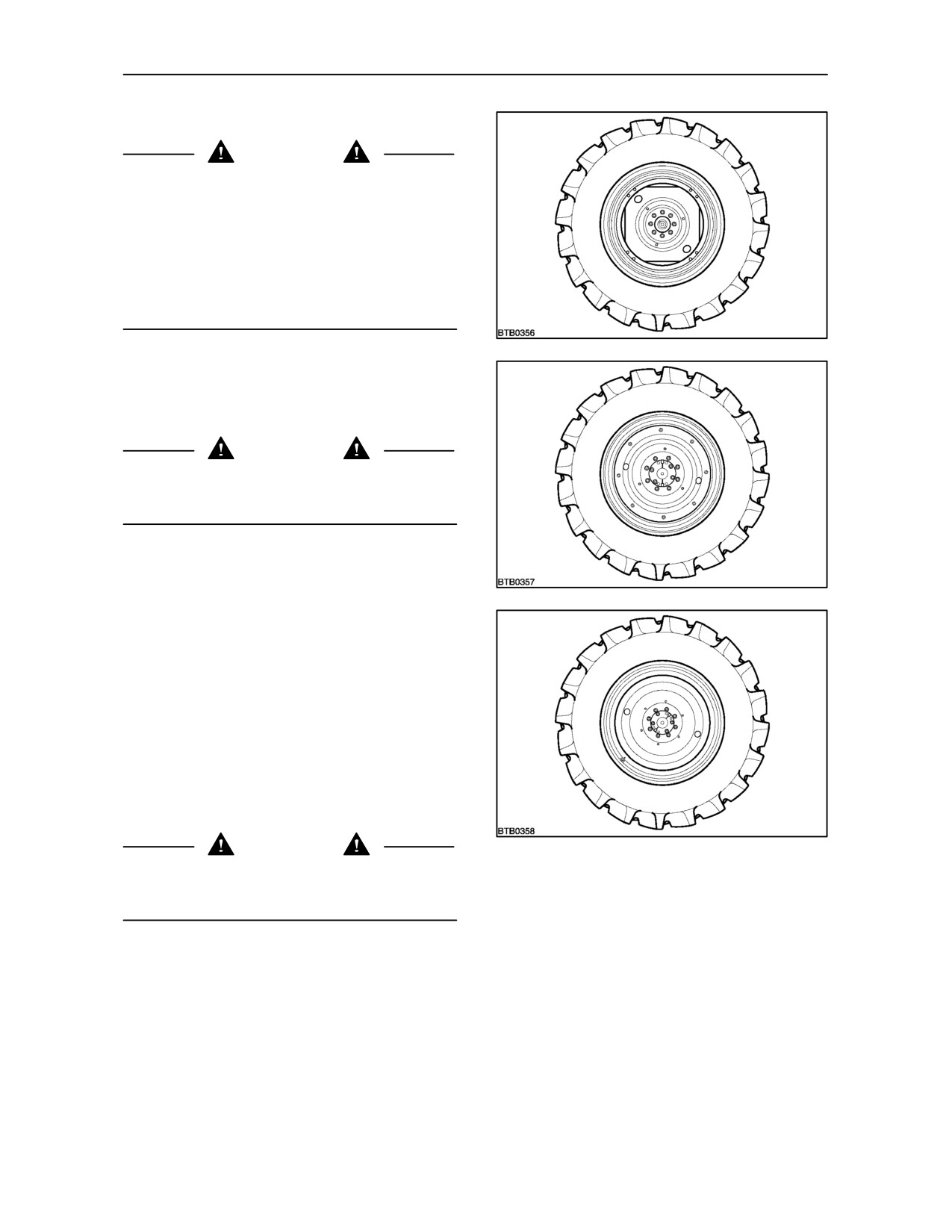
NOTE: There are three different designs of centre
disc dependent upon tyre size and tractor model.
The centre discs shown are as follows:
222
3
Square centre disc -- variable track (Type 1)
Round centre disc -- variable track (Type 2)
Round centre disc -- fixed track (Type 3)
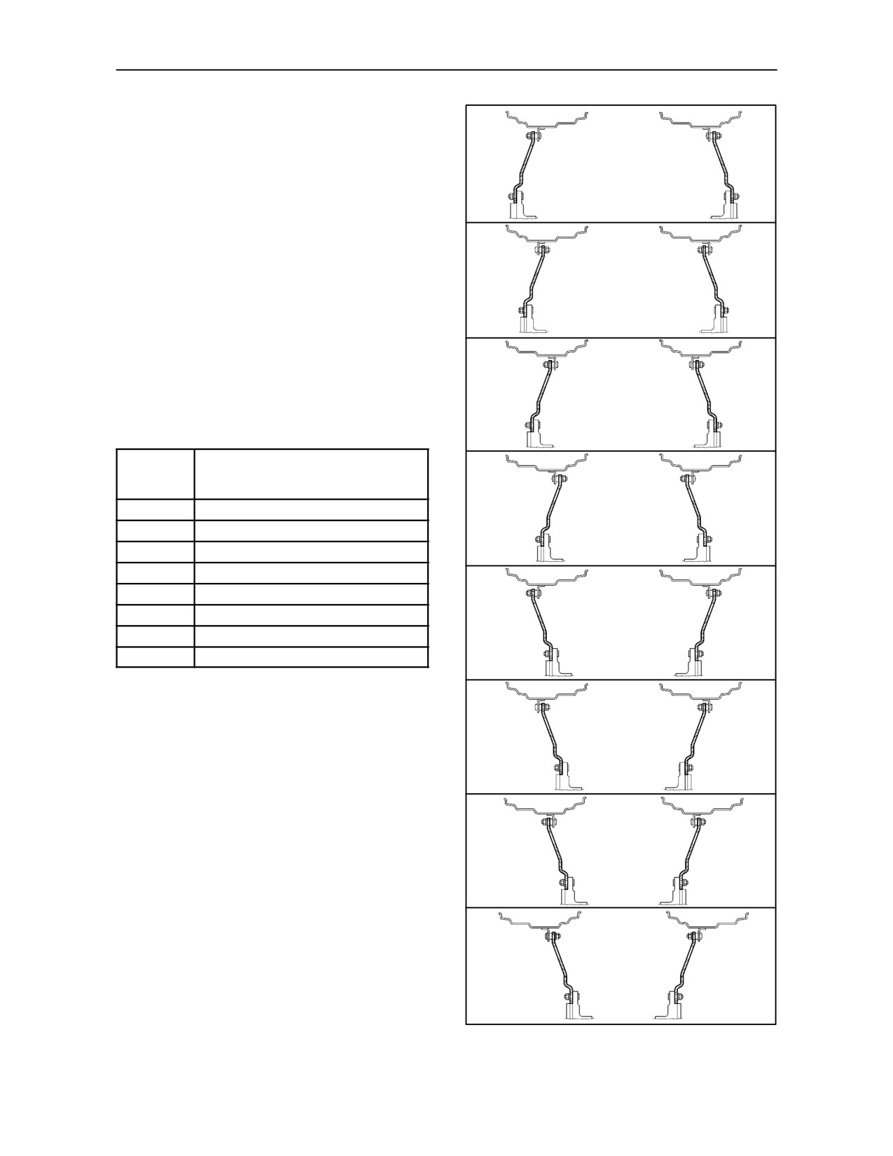
The type of centre disc installed will affect the track
setting. Identify the type of centre disc fitted to your
tractor wheels, then refer to the following table and
Figure 224 to see the wheel rim and disc positions
necessary to achieve the required track setting.
WARNING
223
Never operate the tractor with a loose wheel rim or
disc. Always tighten nuts to the specified torque and
at the recommended intervals.
3--128
SECTION 3 -- FIELD OPERATION
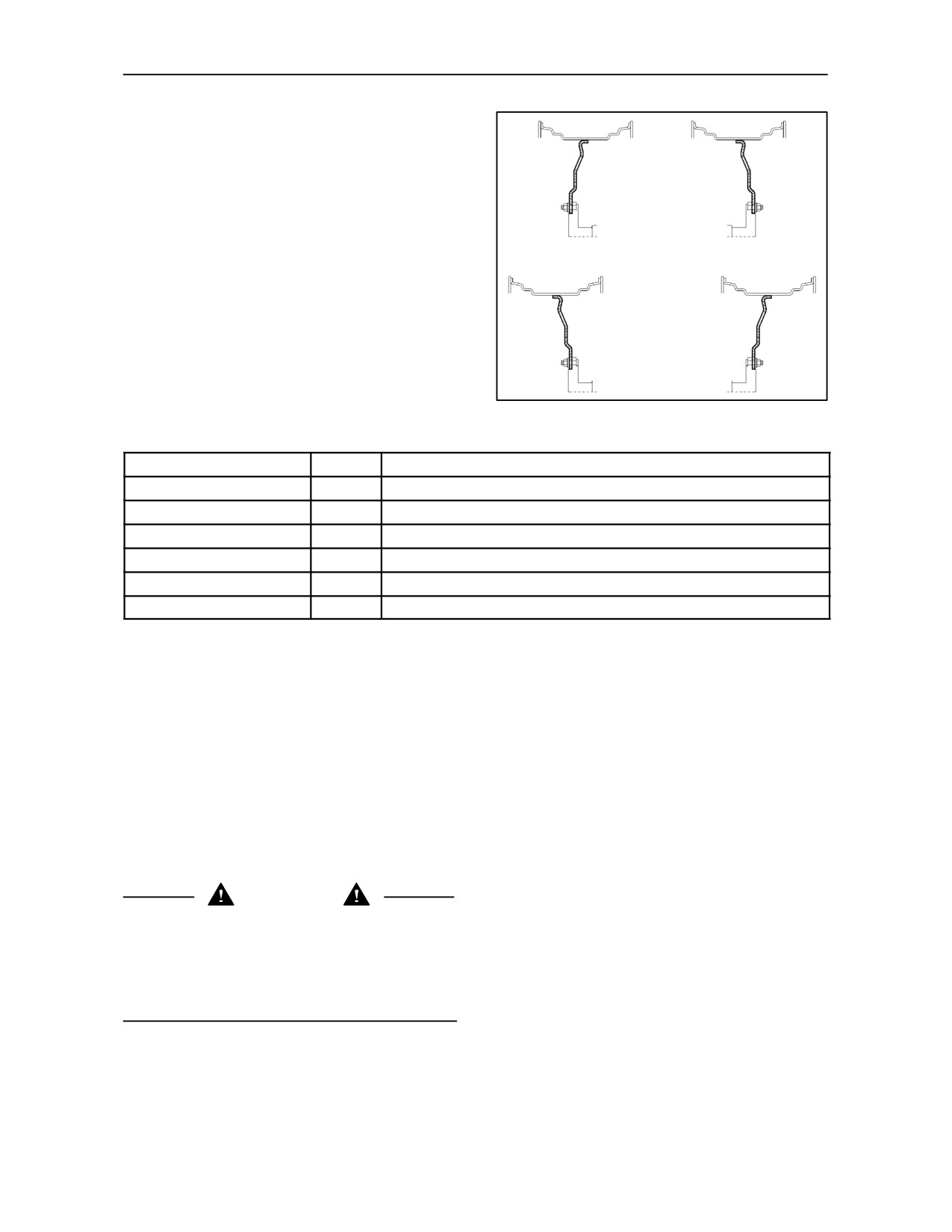
The sectioned drawings shown, illustrate the wheel
rim and disc positions relative to the hub at various
track settings.
A
IMPORTANT: When interchanging left and
right--hand wheel assemblies, ensure the “V” of the
tread at the top of the tyre remains pointing in the
direction of forward travel.
When refitting or adjusting a wheel, tighten the bolts
to the following torques then re-check after 50 hours
of operation and thereafter as required.
B
Rear disc to hub nuts
250 Nm (184 lbf. ft.)
Rear disc to rim nuts
M16 nuts
250 Nm (184 lbf. ft.)
Track Settings
C
Adjustable Rim (Types 1 and 2)
Track
All Models
setting
34” and 38” Wheels
Figure 224
Figures 221, 222
A
1412 mm (55.5 in.)
D
B
1510 mm (59.4 in.)
C
1614 mm (63.5 in.)
D
1710 mm (67.3 in.)
E
1812 mm (71.3 in.)
F
1910 mm (75.1 in.)
E
G
2014 mm (79.2 in.)
H
2110 mm (83.0 in.)
NOTE: With the larger tyre sizes, the narrower track
settings may not be attainable due to minimal
clearance between tyres and fenders or equipment.
The dimensions shown in the above chart relating
F
to Figure 224 are nominal and should be used as
a guide only. Track settings may vary dependent
upon wheel type and tyre size.
G
H
224
3--129
SECTION 3 -- FIELD OPERATION
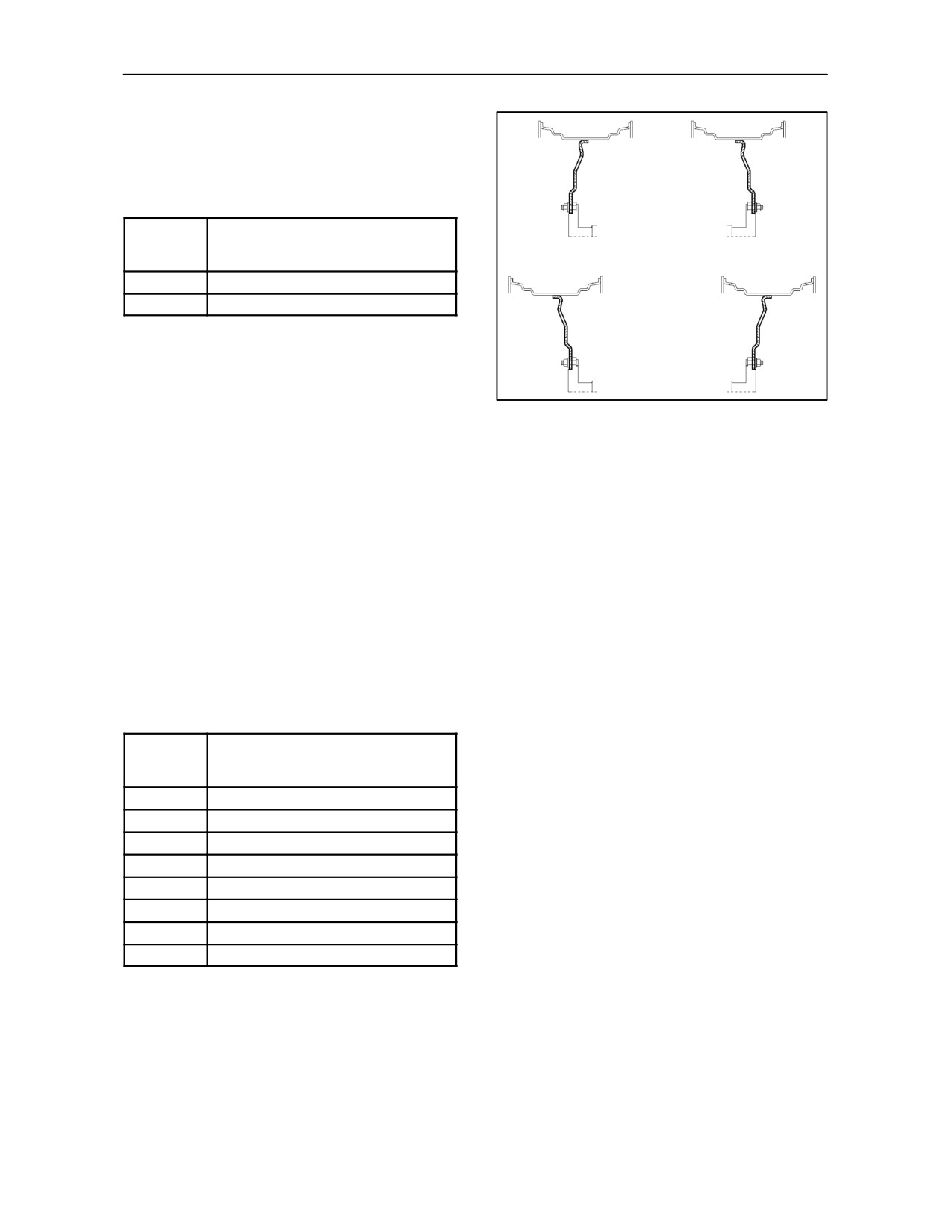
Fixed Rim (Type 3)
A track adjustment of approximately 50 mm (2.0in.)
each side, may be achieved by interchanging wheel
assemblies.
A
Track
Disc type 3
setting
(18.4 x 38 tyre)
Figure 225
Figure 223
A
1730 mm (68.1 in.)
B
1834 mm (72.2 in.)
NOTE: Depending on rim type, the above settings
B
may vary by approximately 10.0mm (0.4 in.).
225
TOBACCO AXLE
(North America only)
If your tractor has theoptional Tobaccoaxle, thenthe
track settings shown in the table on page 3--129 are
increased by 152 mm (6 in) by the addition of spacers
between the wheels and the rear axle flanges.
When refitting or adjusting a wheel, tighten the bolts
to the following torques then re-check after 50 hours
of operation and thereafter as required.
Disc to hub nuts
250 Nm (184 lbf. ft.)
Disc to rim nuts
250 Nm (184 lbf. ft.)
Track
Tobacco Axle
setting
34” and 38” Wheels
Figure 224
Figures 221, 222
A
1564 mm (61.5 in.)
B
1662 mm (65.4 in.)
C
1766 mm (69.5 in.)
D
1862 mm (73.3 in.)
E
1964 mm (77.3 in.)
F
2062 mm (81.1 in.)
G
2166 mm (85.2 in.)
H
2262 mm (89.0 in.)
3--130
SECTION 3 -- FIELD OPERATION
BAR AXLE (where fitted)
CAUTION
Your tractor is produced with lights that meet lighting
regulations when operating or travelling on the public
highway. If the wheel track setting is adjusted beyond
the initial factory position then you may be required
to reposition the lights or fit auxiliary lighting to
comply with legal requirements. Additionally, before
travelling on the highway, ensure that the overall
tractor width does not exceed the maximum
permitted in your country.
INTRODUCTION
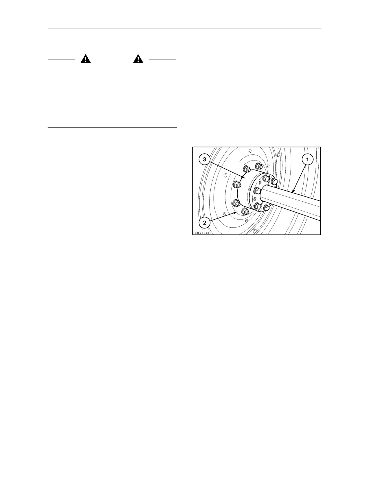
Tractors equipped with a bar axle may have fixed or
manual adjust wheels. The wheels are attached to a
cast iron hub (3) which is clamped to the bar axle (1).
After unclamping the hub, the wheel may be moved
along the bar to provide a range of track widths. A
range of 190 mm (7.5 in.) of movement per wheel, or
380 mm (15 in.) overall, is available with the 98 inch
axle.
Track width adjustment is effected by moving the
complete wheel/hub assemblies in or out on the axle
226
shaft. Reduce the track width by moving the wheel
towards the tractor, increase the width by moving the
wheel outwards.
Additionally, repositioning the wheel rim on the
centre disc or reversing the centre disc on the axle
hub will provide a wider range of adjustment.
Tractor wheels are very heavy so it is recommended
that you do not remove them to reposition the rims
on the disc unless the track setting required is
outside the slide range of the bar axle.
3--131
SECTION 3 -- FIELD OPERATION
MOVING A WHEEL ON THE AXLE SHAFT
Block the front wheels and jack up and support the
rear axle.
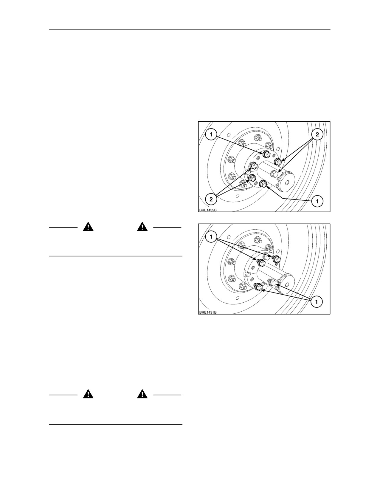
Adjustment of the track setting is achieved by sliding
the complete wheel/hub assembly on the axle shaft.
Loosenthetwocentrewedgebolts(1)Figure 227,
approximately 0.5 in. (12 mm). Remove the four
outer wedge bolts (2).
Clean the bolts and threaded holes in the wedges
before lubricating and installing the outer wedge
bolts at (1) Figure 228. These bolts are used as jack
bolts to push against the wedges. Tighten the jack
bolts evenly until the wedges loosen on the axle
shaft. The wheel assembly will now be free to slide
in or out on the axle shaft.
IMPORTANT: Do not use a torque greater than 300
ft.lbs.
(407 N⋅m) on the jack bolts. The use of
penetrating oil between the wedge and axle shaft will
be of benefit. If difficulty is experienced, place a shaft
protector over the end of the axle shaft and strike with
a hammer to ‘shock’ the wedge free.
227
WARNING
Take suitable precautions, including the use of safety
glasses, against the possibility of flying metal
particles.
Set the wheel to the desired position on the shaft.
Remove the jack bolts and replace them in the outer
holes (2) Figure 228.
Tighten all six wedge retaining bolts in increments
of 50 ft.-lbs. (68 Nm) until a final torque of 221 ft.-lbs.
(300 Nm) is achieved.
IMPORTANT: The wedge bolts must be tightened
228
evenly.
Repeat the procedure on the other wheel, making
sure that both rear wheels are the same distance
from the ends of the axle shafts.
NOTE: Check the torque of all six wedge retaining
bolts on each wheel after driving the tractor for 200
yards (200 m), after 1 hour and 10 hours operation
and thereafter at the 50-hour service intervals.
WARNING
Never operate the tractor with a loose wheel rim or
disc. Always tighten nuts to the specified torque and
at the recommended intervals.
3--132
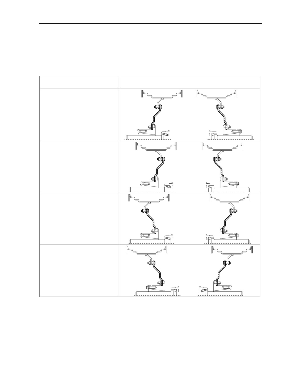
SECTION 3 -- FIELD OPERATION
WHEEL ADJUSTMENT
The sectioned drawings shown in Figures 229 and 230 illustrate the wheel rim and disc positions at various track
settings. In each table, two track width settings are quoted for each axle type. These are the minimum and
maximum achievable with both wheel assemblies moved fully in (toward the tractor) and fully out (away from
the tractor).
Track Adjustment
Rim and Disc Position
1524 -- 1830 mm (60 -- 72 in.)
1727 -- 2030 mm (68 -- 80 in.)
1930 -- 2235 mm (76 -- 88 in.)
2133 -- 2438 mm (84 -- 96 in.)
229
Wheels with steel centre disc bolted to flange on the rim
NOTE: With the larger width tyres, it may not be
NOTE: The track widths shown in Figure 229 are
possible to move the wheels to the narrower settings
nominal and may vary from that shown dependent on
due to limited clearance between the tyre and fender.
wheel and tyre size.
3--133
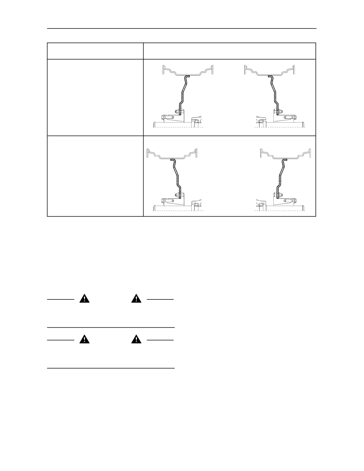
SECTION 3 -- FIELD OPERATION
Track Adjustment
Rim and Disc Position
1524 -- 2133 mm (72 -- 84 in.)
1625 -- 2235 mm (64 -- 88 in.)
230
Wheels with steel centre disc welded to flange on the rim
NOTE: The track widths in Figure 230 are nominal
When refitting or adjusting a wheel, tighten the bolts
and may vary from that shown dependent on wheel
to the following torques then re-check after 50 hours
and tyre size.
of operation and thereafter as required.
NOTE: With the larger width tyres, it may not be
IMPORTANT: When interchanging left and
possible to move the wheels to the narrower settings
right--hand wheel assemblies, ensure the “V” of the
due to limited clearance between the tyre and fender.
tread at the top of the tyre remains pointing in the
direction of forward travel.
CAUTION
Tractor wheels are very heavy. Handle with care and
Disc to hub nuts
ensure, when stored, that they cannot topple and
8 Stud, steel disc wheels
260 Nm (190 lbf. ft.)
cause injury.
Disc to rim nuts
Steel disc wheels
M16 nuts
240 Nm (177 lbf. ft.)
WARNING
Never operate the tractor with a loose wheel rim or
disc. Always tighten nuts to the specified torque and
at the recommended intervals.
3--134
SECTION 3 -- FIELD OPERATION
BALLASTING AND TYRES
Selecting Ballast
GENERAL
When tractor horsepower loads vary, the optimum
weight of the tractor will change. This means that
ballast may have to be added or removed to maintain
Maximum tractor performance is dependent upon
the best tractor performance. Proper ballast will
proper ballasting and tyre selection. Maximum
greatly improve tractor operation and ride.
efficiency will be achieved when tractor weight is
correct for the application.
The amount of ballast required is affected by:
The tyres selected for your tractor must be able to
• Weight of tractor
support the weight of the tractor and equipment and
must also be able to provide adequate traction to
• Soil and traction conditions
utilize the tractor horsepower and turn it into useful
drawbar horsepower.
• Type of implement: fully-mounted, semi-
mounted or trailed
Always maintain the correct air pressure in the tyre
to carry the load. Do not over inflate tyres.
• Working speed
NOTE: Radial tyres will work with lower air pressures
• Tractor horsepower load
and will show up to 20% sidewall deflection or bulge
when correctly inflated.
• Type and size of tyres
Factors Affecting Tyre Performance
• Tyre pressures
• Correct air pressure for the load
Do not use more ballast than needed. Excess ballast
should be removed when it is not required.
• Correct sidewall deflection
IMPORTANT: Only sufficient weight should be
added to provide traction and stability. Adding more
• Correct wheel slip
weight than necessary results in unnecessary loads
being imposed on the tractor and a higher fuel
• Correct tyre size for expected load
consumption. When adding weight, adhere to the
maximum tyre capacity loading stated in the tables
• Correct fill of liquid ballast
commencing on page 3--144. If further information or
assistance is required on tractor weighting consult
• Maintaining equal tyre pressure in both tyres on
your authorised dealer.
a given axle
3--135
SECTION
3
-- FIELD OPERATION
Too little ballast:
For optimum performance and efficiency, two wheel
drive tractors should be ballasted so that
approximately one third of the total tractor weight
• Rough ride
(less implement) is on the front wheels. Four wheel
drive tractors should be ballasted so the weight on
• Excessive wheel slip
the front wheels is approximately 40 -- 45% of the
total tractor weight.
• Power loss
Add additional front end ballast, as required, for
• Tyre wear
stability during operation and transport. Ballasting of
the front end may not always provide adequate
• Excessive fuel consumption
stability if the tractor is operated at high speed on
rough terrain. Reduce tractor speed and exercise
• Lower productivity
caution under these conditions.
Too much ballast:
When using front mounted implements it may be
necessary to add weight to the rear wheels to
maintain traction and stability.
• Higher maintenance costs
BALLASTING WITH FRONT AXLE
• Increased driveline wear
SUSPENSION
• Power loss
IMPORTANT: On tractors fitted with front axle
suspension, correct ballasting is essential to
• Increased soil compaction
optimise suspension operation, particularly when
using heavy rear mounted equipment. For this
• Excessive fuel consumption
application, sufficient front ballast must be added by
the use of wafer weights in preference to liquid
• Lower productivity
ballast in the tyres
In certain conditions, with insufficient front weight
added, suspension operation may become disabled
For maximum performance in heavy draft conditions
and error code 10007 displayed. Stop the tractor,
weight should be added to the tractor in the form of
switch off the engine and restart again to clear the
liquid ballast, cast iron weights or a combination of
error code and re--enable the suspension. If the error
both.
code re--occurs, then further front weight should be
added ensuring maximum axle and vehicle weights
Front end ballast may be required for stability and
are not exceeded.
steering control when weight is transferred from the
front to the rear wheels as rear mounted implement
Ballast Limitations
is raised by the tractor 3-point linkage.
Ballast should be limited by the tyre capacity or
When a rear mounted implement is raised to the
tractor capacity. Each tyre has a recommended
transport position, the weight on the front wheels
carrying capacity which should not be exceeded,
should be at least 20% of total tractor weight.
(see pages 3--144 and 3--145 ).
CAUTION
If a greater amount of weight is needed for traction,
Additional front ballast may be needed when
larger tyres should be used.
transporting large
3-point mounted equipment.
Always drive slowly over rough terrain, no matter
Ballast can be added by bolting on cast iron weights
how much front ballast is used.
or by adding liquid calcium chloride in the tyres.
Bolt-on cast iron weights are recommended because
they can easily be removed when not needed.
3--136
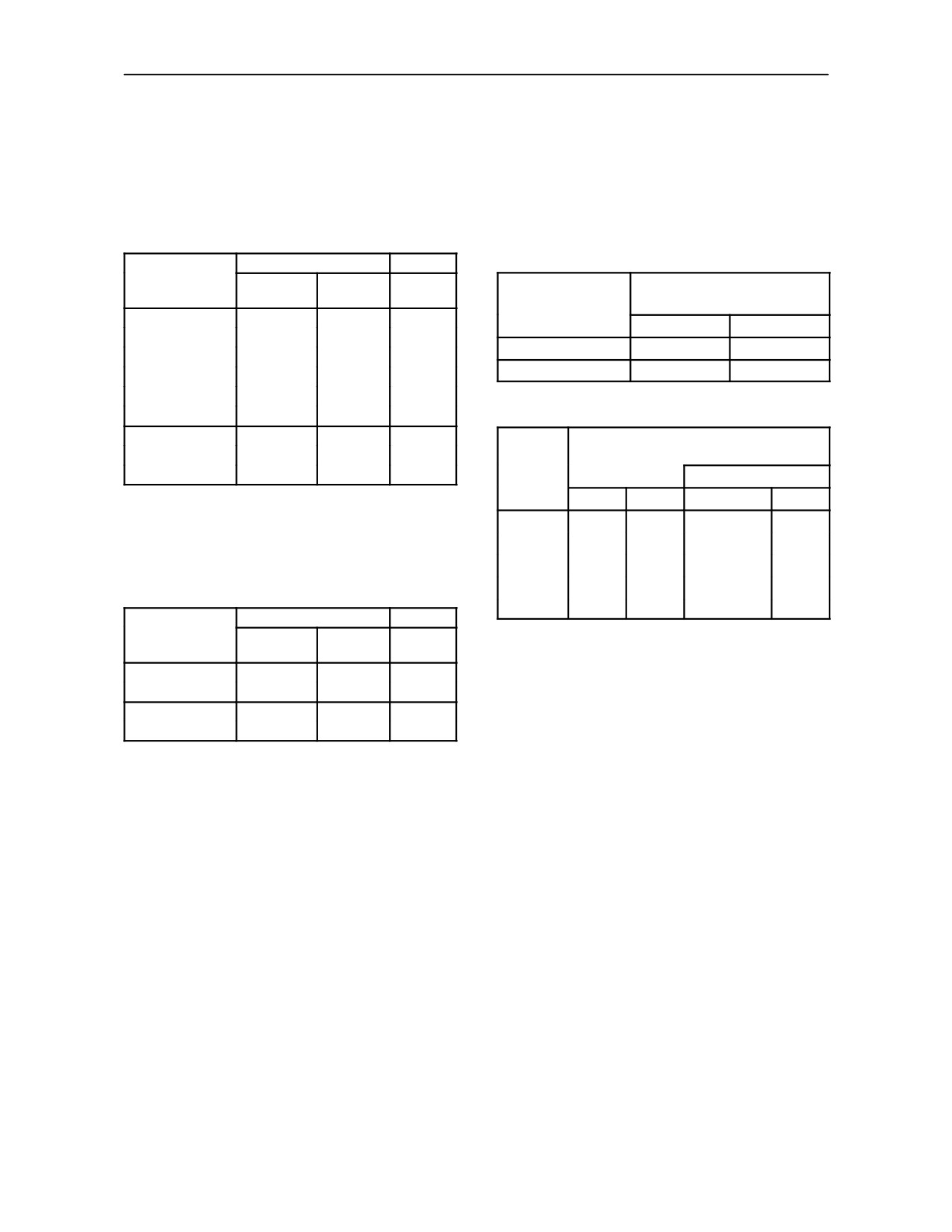
SECTION 3 -- FIELD OPERATION
TRACTOR WEIGHT INFORMATION
Restricted Operation
Maximum Gross Vehicle Weight
IMPORTANT: For intermittent operation, the front
axle loading (including loaded loader bucket) may be
The maximum axle loads and vehicle weights will
increased (see Restricted Operation), provided
differ by model, depending on the type and
that the ground speed does not exceed 8 km/h (5
combination of front and rear axles fitted to the
MPH) and the front track width settings are
tractor.
maintained within the limits shown:
Maximum Axle Load
G.V.W.
2WD Models
Total
Maximum Front Axle Loading
Front (kg)#
Rear (kg)
(kg)
(Restricted Operation)*
2WD Models
2449
(LF)
6260
(LR)
7500
kg
lb
2449
(LF)
6500
(HR)
7500
Standard Axle
5000
11022
2994
(HF)
6260
(LR)
7500
T6010/T6020
Heavy Duty Axle
5000
11022
2994
(HF)
7000
(HR)
8100
1361
(WD)
6260
(LR)
7500
* Maximum track setting 1829 mm. (72.0 in.).
1361
(WD)
7000
(HR)
8100
2449
(LF)
6500
(HR)
7500
Maximum Front Axle Loading
T6030/T6050
2994
(HF)
7000
(HR)
8100
4WD
(Restricted Operation)
Class
3
1361
(WD)
7000
(HR)
8100
Track Setting
Axle
kg
lb
mm
in
(LF) =
Light Duty front axle with six stud wheel
fixing at maximum 72” track setting.
T6010
6200
13668
1727 -- 2032
68 -- 80
(HF) = Heavy Duty front axle with eight stud
T6020
6200
13668
1727 -- 2032
68 -- 80
wheel fixing at maximum 72” track setting.
T6030
6200
13668
1727 -- 2032
68 -- 80
(WD) = Wide front axle with eight stud wheel
fixing.
T6050
6200
13668
1727 -- 2032
68 -- 80
T6070
6200
13668
1727 -- 2032
68 -- 80
Maximum Axle Load
G.V.W.
4WD Models
Total
Front (kg)#
Rear (kg)
(kg)
NOTE: Total axle weight is measured with only the
3600
6260
(LR)
7500
T6010/T6020
front or rear wheels on the scales inclusive of liquid
3600
7000
(HR)
8100
and cast iron ballast and with mounted equipment in
3600
7000
(HR)
8700
T6030/T6050
the raised position.
T6070
3600
7000
(HR)
8700
IMPORTANT: Do not exceed the tractor gross
vehicle weights shown. This can cause an overload
IMPORTANT: # Includes front mounted equipment
condition that may invalidate the warranty and may
or loader in the raised position but with no load in the
exceed the load rating of the tyres. The maximum
bucket.
recommended gross vehicle weight is the weight of
(LR) = Light Duty rear axle.
the tractor plus ballast plus any mounted equipment
(HR) = Heavy Duty rear axle.
such as sprayers, tanks etc. in the raised position.
(see page 3--138 for axle identification)
IMPORTANT: Braking regulations in some countries
may impose lower gross vehicle weight limits for road
transport than the figures quoted in the above tables.
3--137
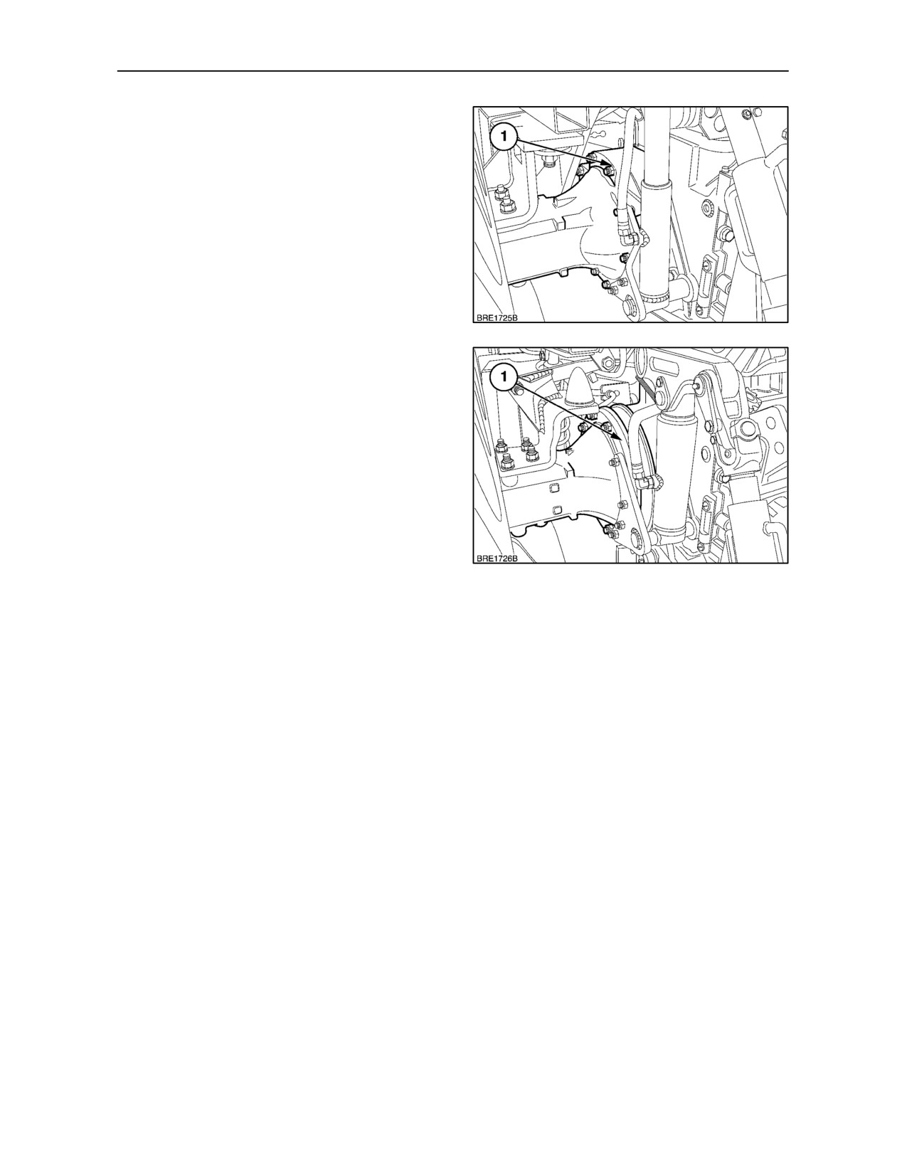
SECTION 3 -- FIELD OPERATION
REAR AXLE RECOGNITION
Light Duty Rear Axle
Your tractor may be fitted with a light duty, heavy duty
or bar type rear axle depending on specification. The
rear axles can be identified by the shape of the
planetary reduction housings (1) shown in the two
illustrations.
231
Heavy Duty and Bar Type Rear Axle
NOTE: Total rear axle weight is measured with only
the rear wheels on the scales inclusive of liquid and
cast iron ballast and with mounted equipment in the
raised position.
232
3--138
SECTION 3 -- FIELD OPERATION
CAST IRON WEIGHTS
(where fitted)
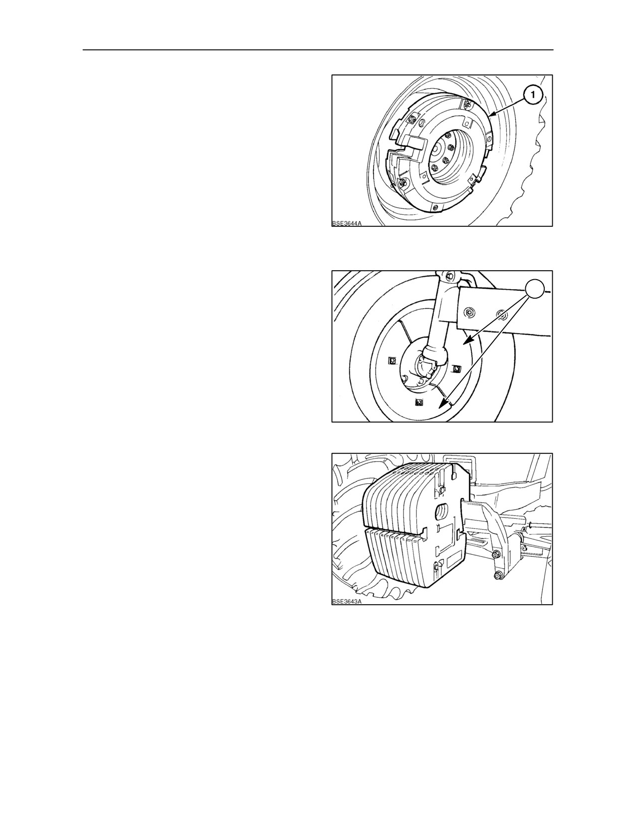
Rear wheel weights
Up to three cast iron weights (1), may be added to
each rear wheel.
With flanged axle: 6 x 45 kg (6 x 99 lb.) permitting a
maximum of 270 kg (594 lb.) to be carried.
With bar axle: 6 x 65 kg (6 x 143 lb.) permitting a
maximum of 390 kg (860 lb.) to be carried.
IMPORTANT: It is not recommended to fit rear
wheel weights on tractors operating at speeds in
233
excess of 40 k/mh (25 MPH).
Front wheel weights
1
For two wheel drive front wheels, segmented, cast iron
wheel weights (1), are available as an accessory. The
set of four (two per wheel) provides a total front wheel
ballast weight of 78 kg (172 lb.).
234
Front end wafer weights
Front end wafer weights are available in sets as
described in the following text.
45 kg (99 lb.) wafer weights are available in sets of
6,
10 and 18 which, together with the support
carrier and tow hook, weigh:
6 weights, including carrier
360 kg. (793 lb.)
and tow hook.
10 weights, including carrier
540 kg. (1190 lb.)
and tow hook.
235
18 weights, including carrier
900 kg. (1984 lb.)
and tow hook.
3--139
SECTION 3 -- FIELD OPERATION
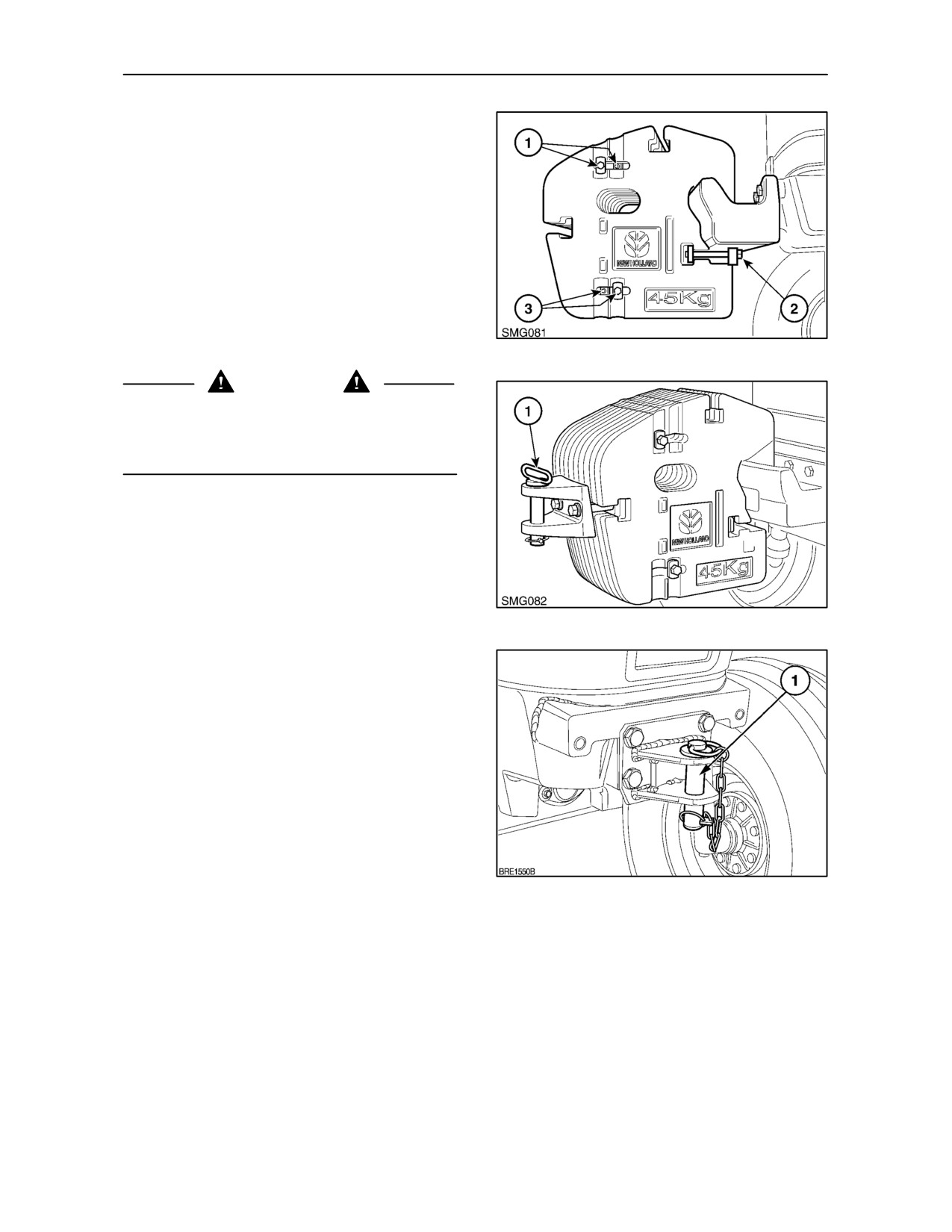
The weights are clamped together by means of the
long through bolts (1) and (3) and secured to the
carrier by the clamp bolts (2).
The weights may be removed as a complete set with
the aid of suitable lifting gear. Loosen the clamp bolts
(2) and slide the clamp assembly sideways out of the
weight pack. With a lifting bar passed through the
central hole, the complete weight set may now be
lifted off the carrier.
Alternatively, the weights can be removed
individually after loosening the clamp bolts and
removing all four through bolts (1) and (3).
236
WARNING
The tractor must not be operated unless all four
through bolts and the clamp bolts are in position with
the bolts tightened to 169 Nm (125 lbf.ft.). Recheck
the bolt torques after 50 hours of operation.
A towing facility is built into the weight carrier.
However, if the weights are installed a tow pin (1), is
available that clamps onto the front of the weight
pack.
237
If the front weights and weight carrier are not
installed, a tow pin is available for bolting directly to
the front axle support.
238
3--140
SECTION 3 -- FIELD OPERATION
LIQUID BALLAST
IMPORTANT: It is not recommended to use liquid
The figures in the table will give a 75% fill of the tyre.
This calcium chloride/water solution will give
ballast on tractors operating at speeds in excess of
protection from freezing down to an ambient
40 Km/h (25MPH) asride qualitymay beadversely
temperature of --50°C (--58°F).
affected.
WARNING
Filling the front and rear tyres with liquid ballast is a
When mixing the ballast solution it is imperative the
convenient method of adding weight. A solution of
calcium chloride flakes are added to the water and
calcium chloride and water is recommended. This
the solution stirred until the calcium chloride is
gives a low freezing point and provides a higher
dissolved.
density than plain water.
Never add water to calcium chloride as considerable
heat is generated. If the flakes should contact the
IMPORTANT: In some countries it is illegal to use
eyes, wash the eyes immediately with clean, cold
calcium chloride as a ballast solution for tyres.
water for at least 5 minutes. Consult a doctor as soon
Ensure that you comply with the legal requirements
as possible.
of your country. Use cast iron weights as an
alternative to liquid ballast.
The following tables show the quantity of calcium
chloride and water required for each tyre size option
and is based on 0.6 kg of calcium chloride per litre of
water.
Front Tyre Ballast
Tyre Size
Water
Calcium
Total Weight
Water
Calcium
Total Weight
Chloride
of solution
Chloride
of solution
per tyre
US
per tyre
Litres
kg.
kg.
gallons
lb.
lb.
11.4 -- 24
77
46
123
21
102
273
12.4R -- 24
94
56
150
25
124
331
13.6R -- 24
123
73
196
33
162
433
14.9R -- 24
151
90
241
40
176
471
13.6R -- 28
119
71
190
31
157
417
14.9R -- 28
170
102
272
45
224
599
16.9R -- 28
219
131
350
58
290
774
14.9R -- 30
174
104
278
46.0
231
616
380/70R -- 24
117
70
187
31
155
414
420/70R -- 24
149
89
238
39
197
526
380/70R -- 28
144
86
230
38
190
508
420/70R -- 28
166
99
265
44
219
585
440/65R -- 28
167
100
267
44
220
588
480/65R -- 28
200
120
320
53
264
705
480/70R -- 28
222
133
355
59
294
785
520/60R -- 28
210
126
336
56
278
742
540/65R -- 28
251
150
401
66
332
886
320/85R -- 34
107
64
171
28
142
379
NOTE: Liquid ballasting of front tyres on a two wheel drive installation is not recommended.
3--141
SECTION 3 -- FIELD OPERATION
Rear Tyre Ballast
Tyre Size
Water
Calcium
Total Weight
Water
Calcium
Total Weight
Chloride
of solution
Chloride
of solution
per tyre
US
per tyre
Litres
kg.
kg.
gallons
lb.
lb.
18.4R --
30
286
171
457
76
377
1007
12.4
--
32
123
73
196
33
163
436
16.9R --
34
270
162
432
71
357
952
18.4R --
34
292
175
467
77
386
1031
13.6R --
38
176
105
281
47
233
622
16.9R --
38
275
165
440
73
364
972
18.4R --
38
312
187
499
83
413
1102
20.8R --
38
429
257
686
113
567
1513
18.4R --
42
352
211
563
93
465
1241
14.9R --
46
245
147
392
65
324
865
480/70R --
34
248
148
396
66
328
875
520/70R --
34
307
184
491
81
406
1083
480/70R --
38
270
162
432
72
357
954
520/70R --
38
318
190
508
84
420
1121
540/65R --
38
316
189
505
84
418
1115
600/60R --
38
365
219
584
97
483
1289
600/65R --
38
419
257
670
111
554
1479
650/60R --
38
436
261
697
115
576
1538
650/65R --
38
510
306
816
135
674
1800
320/90R --
50
153
91
244
40
202
539
IMPORTANT: Only sufficient weight should be
WARNING
added to provide traction and stability. Adding more
Tractor wheels are very heavy. Handle with care and
weight than necessary results in unnecessary loads
ensure, when stored, that they cannot fall and cause
being imposed on the tractor and a higher fuel
injury.
consumption. When adding weight, adhere to the
Never operate the tractor with a loose wheel rim or
maximum tyre capacity loading stated in the tables
disc. Always tighten nuts to the specified torque and
commencing on page 3--144. If further information or
at the recommended intervals.
assistance is required on tractor weighting consult
your authorised dealer.
3--142
SECTION 3 -- FIELD OPERATION
TYRE CARE
Upon receiving your tractor, check the air pressure
•
After seating the beads, adjust inflation pressure
in the tyres and recheck every 50 hours or weekly.
to the recommended operating pressure.
When checking tyre pressures, inspect the tyres for
•
Do not re-inflate a tyre that has been run flat or
damaged tread and side walls.
seriously under-inflated until it has been
inspected for damage by a qualified person.
Inflation pressure affects the amount of weight that
a tyre may carry.
•
Torque wheel to axle nuts to specification after
re-installing the wheel. Check nut tightness daily
until torque stabilises.
See the Tyre Pressure and Load tables, pages 3--144
and 3--145. Do not exceed the load for the pressures
listed. Do not over or under inflate the tyres. If the tyre
•
Refer to tractor weighting section before adding
fitted to your tractor is not listed, consult your
ballast to the tyres.
authorised dealer for pressure and load information.
•
Ensure the jack is placed on a firm, level surface.
WARNING
Inflating or servicing tyres can be dangerous.
•
Ensure the jack has adequate capacity to lift your
Whenever possible, trained personnel should be
tractor.
called in to service or install tyres. In any event, to
avoid the possibility of serious or fatal injury, follow
•
Use jack stands or other suitable blocking to
the safety precautions below:
support the tractor while repairing tyres.
•
Do not put any part of your body under the tractor
• Never attempt tyre repairs on a public road or
or start the engine while the tractor is on the jack.
highway.
•
Never hit a tyre or rim with a hammer.
• Do not inflate a steering tyre (front tyre on a two
wheel drive tractor) above the manufacturer’s
•
Ensure the rim is clean and free of rust or
maximum pressure shown on the tyre or beyond
damage. Do not weld, braze, otherwise repair or
the maximum recommended by your authorised
use a damaged rim.
dealer or tyre supplier.
•
Do not inflate a tyre unless the rim is mounted on
• Never inflate a traction tyre (front tyre on a four
the tractor or is secured so that it will not move
wheel drive tractor or any rear tyre) over 2.8 bar
if the tyre or rim should suddenly fail.
(40 lbf/in2). If the bead does not seat on the rim
by the time this pressure is reached, deflate the
•
When fitting a new or repaired tyre, use a clip-on
tyre, relubricate the bead with a soap/water
valve adaptor with a remote gauge that allows
solution and re-inflate. Do not use oil or grease.
the operator to stand clear of the tyre while
Inflation beyond 2.8 bar with unseated beads
inflating it. Use a safety cage, if available.
may break the bead or rim with explosive force
sufficient to cause a serious injury.
3--143
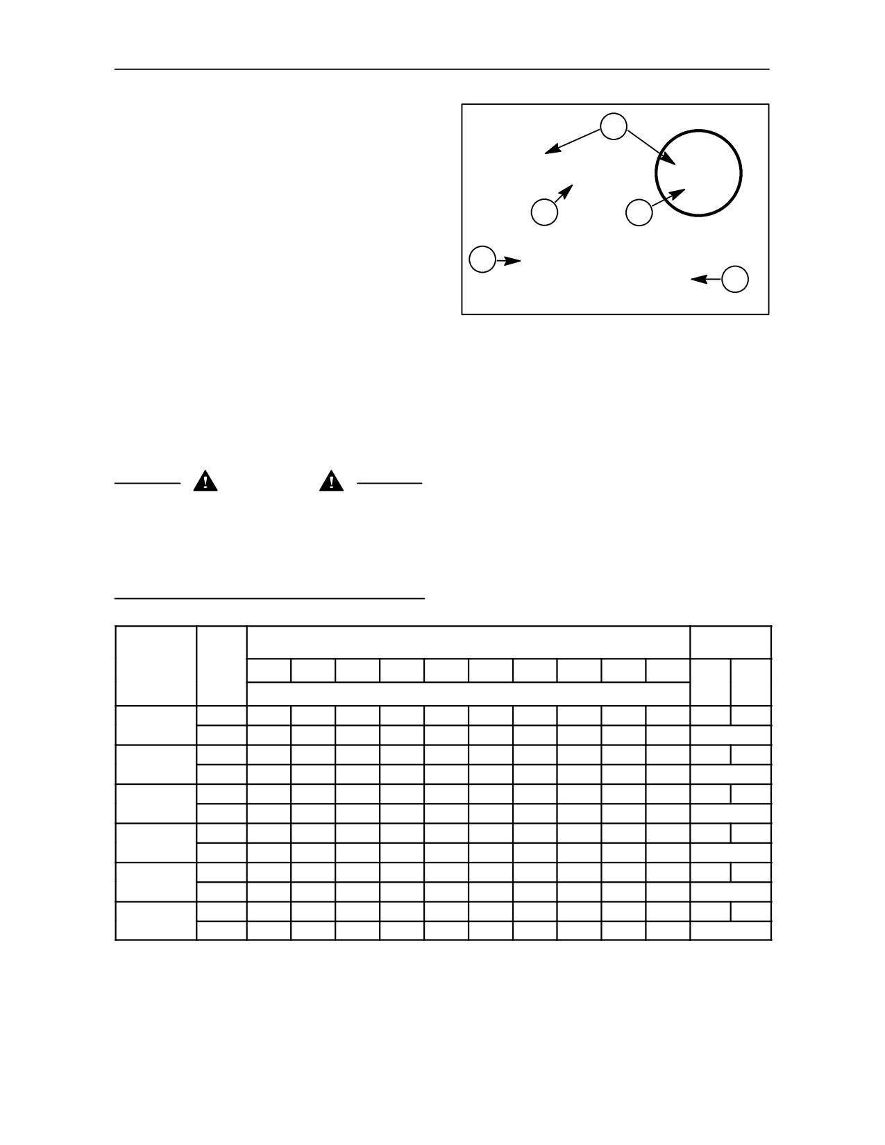
SECTION 3 -- FIELD OPERATION
TYRE PRESSURES AND PERMISSIBLE LOADS
1
Radial tyre performance is denoted by a Load Index
138
and Speed Symbol replacing the Ply Rating
141 A8
commonly found on cross ply tyres. Figure
239
B
shows typical markings to be found on the side wall
2
3
of radial ply tyres.
MAX LOAD AT 40 KM/H
NOTE: Radial tyres will have a speed symbol of ‘A8’
4
2575 KGS AT 1.6 BAR
and/or ’B’which identifies the maximum speed rating
for that tyre. Tyres marked with the A8 symbol are
REPLACES 10 P.R.
5
suitable for speeds up to 40km/h (25 MPH), those
marked with a ’B’ symbol may be operated at speeds
up to 50k/mh (31 MPH).
239
The maximum load that may be carried by the tyre is
1.
Load Index
dependent upon the Load Index shown on the side
2.
Speed Symbol for 40 km/h (25 MPH)
3.
Speed Symbol for 50 km/h (31 MPH)
wall. In the following charts the loads given are for
4.
Maximum load/inflation pressure at
individual tyres operated at speeds up to 40 or 50 km/h
40 km/h (25MPH)
(25 or 31 MPH). The two right--hand columns indicate
5.
Old ply rating mark
the maximum permissible load per tyre at speeds of
40 or 50 km/h (25 or 31 MPH).
WARNING
When operating at high road speeds, tyre pressures
and maximum load capacities advised by the tyre
manufacturer should be strictly adhered to. Consult
your authorised dealer or tyre supplier for the correct
pressures and loads for the tyres fitted to your
tractor.
Tyre Load
Inflation Pressure -- bar
Capacity @
Tyre
Load
1.0
1.2
1.4
1.6
1.8
2.0
2.2
2.4
2.6
2.8
Size
Index
40
50
Load Capacity per TYRE (kg) @ 30k/mh
k/mh
k/mh
125A8
1295
1415
1530
1650
--
--
--
--
--
--
1650
--
380/70 R24
122B
1295
1415
1530
1650
--
--
--
--
--
--
1650
123A8
1170
1275
1320
1400
--
--
--
--
--
--
1400
--
13.6R--28
120B
1285
1400
1450
1550
--
--
--
--
--
--
1550
142A8
1930
2095
2275
2430
--
--
--
--
--
--
2430
--
18.4R--30
139B
2120
2300
2500
2650
--
--
--
--
--
--
2650
145A8
2300
2500
2700
2900
--
--
--
--
--
--
2900
--
480/70 R38
145B
2300
2500
2700
2900
--
--
--
--
--
--
2900
153A8
--
--
--
--
2210
2410
2460
2865
3140
3350
3350
--
20.8R--38
150B
--
--
--
--
2430
2650
2900
3150
3450
3650
3650
148A8
--
--
--
--
--
--
2300
2725
2900
3150
3150
--
18.4R--42
148B
--
--
--
--
1800
2120
2300
2725
2900
3150
3150
IMPORTANT: The above table provides an example of the maximum load limitations that occur at various tyre
pressures on a representative range of rear tyre sizes available for your tractor. These figures are per tyre and
should be used for guidance only. For exact information regarding inflation pressures and loads for your particular
tyres, consult your authorised dealer.
3--144
SECTION 3 -- FIELD OPERATION
Tyre Load
Inflation Pressure -- lbf/in2
Capacity @
Tyre
Load
15
17
20
23
26
29
31
35
37
40
Size
Index
25
31
Load Capacity per TYRE (lbs.) @ 18.6 MPH
MPH
MPH
125A8
2854
3119
3373
3637
--
--
--
--
--
--
3637
--
380/70 R24
122B
2854
3119
3373
3637
--
--
--
--
--
--
3637
123A8
2579
2810
2910
3086
--
--
--
--
--
--
3086
--
13.6R--28
120B
2832
3086
3196
3417
--
--
--
--
--
--
3417
142A8
4255
4618
5015
5357
--
--
--
--
--
--
5357
--
18.4R--30
139B
4673
5070
5511
5842
--
--
--
--
--
--
5842
145A8
5070
5511
5952
6393
--
--
--
--
--
--
6393
--
480/70 R38
145B
5070
5511
5952
6393
--
--
--
--
--
--
6393
153A8
--
--
--
--
4872
5313
5423
6316
6922
7385
7385
--
20.8R--38
150B
--
--
--
--
5357
5842
6393
6944
7605
8046
8046
148A8
--
--
--
--
--
--
5070
6007
6393
6944
6944
--
18.4R--42
148B
--
--
--
--
3968
4673
5070
6007
6393
6944
6944
IMPORTANT: The above table provides an example of the maximum load limitations that occur at various tyre
pressures on a representative range of rear tyre sizes available for your tractor. These figures are per tyre and
should be used for guidance only. For exact information regarding inflation pressures and loads for your particular
tyres, consult your authorised dealer.
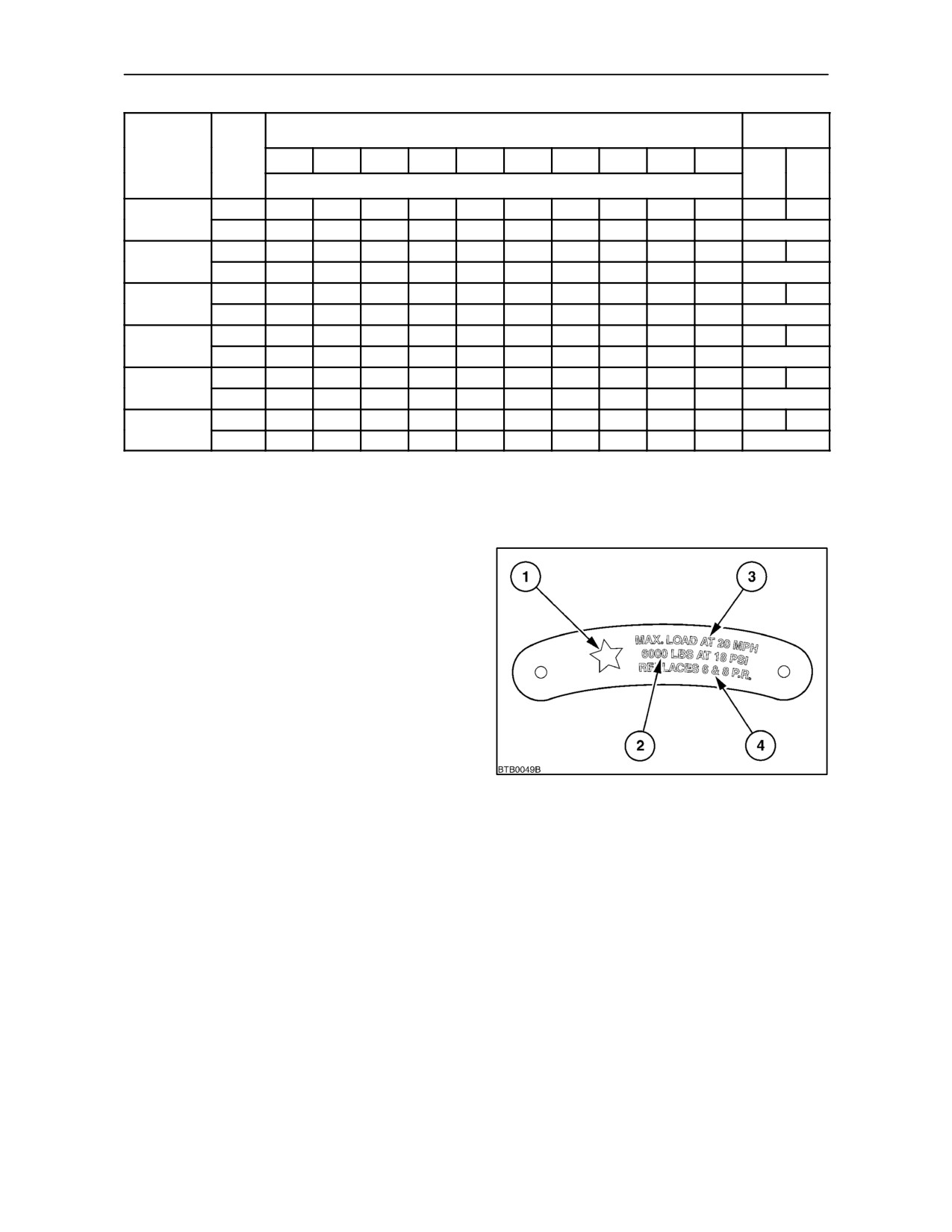
SYMBOL MARKED RADIAL TYRES
(North America Only)
Conventional sized radial agricultural tractor drive
tyres are marked with *, **,or *** symbols. The
maximum load rating for tyres marked with a * is
calculated at 18 psi inflation pressure. Tyres marked
with ** or *** have maximum load carrying capacities
at pressures of 24 psi and 30 psi respectively.
For information regarding specific inflation pressures
and load carrying capacities for the tyres fitted to
your tractor, consult your authorised dealer.
240
1. Load symbol
2. Maximum recommended load at marked pressure
3. Maximum load at 20 MPH
4. Previous ply ratings
3--145
SECTION 4
LUBRICATION AND MAINTENANCE
GENERAL INFORMATION
SAFETY PRECAUTIONS
INTRODUCTION
Read and observe all safety precautions listed in
‘Servicing the Tractor’ in the Introduction section at
the front of this Manual.
Section 4 provides the step by step requirements
necessary to maintain your new tractor in peak
condition. A lubrication and maintenance chart on
NOTE: Dispose of used filters and fluids properly.
page 4--7 provides a ready reference to these
requirements. If in doubt about any aspect of
CAUTION
lubrication and maintenance, consult your dealer.
Do not check, lubricate, service or make adjustments
to the tractor with the engine running.
CONTENTS
The subjects covered in this section are as listed
below. A full index is provided at the back of the book.
Subject
Page
DURING THE FIRST 50 HOURS OPERATION
General Information
4--1
In addition to the regular maintenance operations
First 50--hour service
4--2
listed, check the following items every 10 hours or
Fuelling
4--3
daily during the first 50 hours of operation of your
Guard Removal
4--5
new tractor:
Lubricants and Coolants
4--8
• Check transmission/rear axle/hydraulics oil level
Lubrication and Maintenance Chart
4--10
Servicing when warning lights illuminate
4--11
• Wheel nuts for tightness
10--hour/daily service
4--15
50--hour service
4--17
• Front axle hub oil levels (four wheel drive)
100--hour service
4--26
300--hour service
4--27
CHECKING OIL LEVELS
600--hour service
4--31
IMPORTANT: Park the tractor on level ground and,
1200--hour/12 month service
4--38
where applicable, extend all cylinders before
1200--hour/24 month service
4--43
checking oil levels. With some front/rear wheel
1800--hour service
4--50
combinations, it may be necessary to raise the front
Every 3 years
4--51
or rear of the tractor to ensure it is level before
checking the oil.
General Maintenance -- as required
4--52
4--1
SECTION 4 -- LUBRICATION AND MAINTENANCE
THE FIRST 50 HOUR SERVICE
At the first 50-hour service, ensure that the following
additional service operations are carried out. The
items are listed in the
‘First
50-Hour Service’
checklist in Section 9.
• Check engine oil level
• Change hydraulic oil filters (all models)*
• Check transmission/rear axle/hydraulics oil level
• Check FWD differential oil level
• Check FWD axle hub oil level
• Check and adjust parking brake
• Check all engine air intake connections
• Check torque of exhaust manifold bolts
• Inspect Poly V-belt
• Check and adjust compressor drive belt tension
(air operated trailer brakes--where fitted)
• Tighten all cooling system hose connections
• Check torque of safety cab or frame mounting
bolts
• Check torque of front end weight clamp bolts
(where fitted)
NOTE: Items listed in the first 50-hour check are
important. If not performed, early component failure
and reduced tractor life may result.
*Tractors with Variable Displacement Hydraulic
Pump only
IMPORTANT: At the First 50 Hour service the
hydraulic filter (2) MUST be changed for the larger
capacity service repacement filter. Do NOT replace
with one of the same size as this may reduce
hydraulic system performance.
Filter Dimensions
Length Diameter
Original (factory fit)
204mm
94.3mm
Service replacement filter
254mm
116.8mm
241
4--2