New Holland T6010, T6020, T6030, T6050, T6070 Delta and Plus Tractors. Operator's Manual - page 6
SECTION 3 -- FIELD OPERATION
• It is recommended that a temperature gauge,
Bleeding Remote Cylinders
where available, is installed in the remote circuit
when using hydraulic motors for continuous
When connecting a cylinder with trapped air, i.e., a
operation. If over-heating occurs, stop the
new cylinder, one that has been out of service or one
hydraulic motor until the oil cools. Ensure the flow
that has had the hoses disconnected, it will be
control setting is at maximum and the engine
necessary to bleed the cylinder to remove the air.
speed at a minimum, appropriate to machine
performance.
With the hoses connected to the remote control valve
couplers at the rear of the tractor, position the
If operating conditions are normal and high
cylinder with the hose end uppermost and extend
temperatures persist, install an oil cooler in the motor
and retract the cylinder seven or eight times using the
return circuit. The maximum recommended
remote control valve lever or joystick.
operating temperature of the oil is 110°C (230°F).
Your authorised dealer can supply a suitable oil
cooler and the necessary fittings or make the
Check the
rear axle oil level
before
and
after
installation for you.
operating a remote cylinder.
Operating Several Remote Valves
Simultaneously or Remote Valves and
Hydraulic Lift Simultaneously
NOTE: The hydraulic load-sensing system on your
tractor adjusts the oil flow according to the individual
flow control settings up to the maximum output
possible, dependent upon engine speed. The oil flow
will be relatively constant in the remote control valve
circuits if the flow control valves are used to regulate
the flow, thus providing constant operating speed for
hydraulic motors, etc., even if engine speed varies.
Maintain the engine speed above the minimum
required for simultaneous operation of all the
required circuits and vary ground speed by selection
of the appropriate gear ratio.
If operating two or more remote control valves
simultaneously or remote valves and the hydraulic
lift, all the flow control valves should be adjusted to
provide a partial flow. If not so adjusted, all the
available flow may be directed to the full flow circuit
when the pressure in that circuit is less than that of
the other circuits in use.
3--68
SECTION 3 -- FIELD OPERATION
ELECTRO--HYDRAULIC REMOTE
CONTROL VALVES (where fitted)
NOTE: The Electro--hydraulic remote valves are
only available in conjunction with the Enhanced
keypad.
The electro--hydraulic remote valves operate in a
similar manner to the mechanical valves previously
described. However, with these remote valves, a
number of additional automated functions are
available, supported by visual displays in the Dot
Matrix screen.
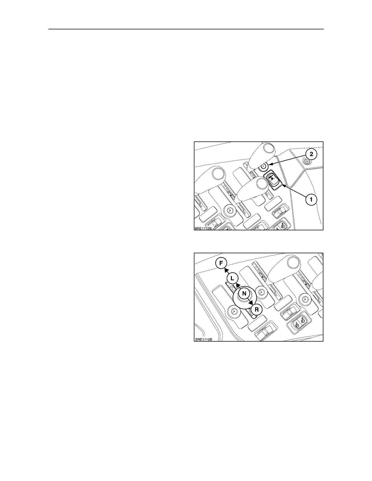
Remote Valve Isolator Switch
The remote valves cannot be operated unless the
system is energised using the isolator switch (1).
Depress the lower part of the switch to activate the
electrical circuit, depress the upper part to
de--activate. When activated, the amber warning
light (2) will be illuminated. The remote valve(s) are
now operational whenever the tractor engine is
running.
IMPORTANT:The isolator switch may be used to
immediately stop operation of the rear remote valves
by depressing the top of the switch. The isolator
switch will only control the remote valves, it has no
120
effect on three point linkage operation.
Control Levers
Each remote valve lever has four positions, extend,
neutral, retract, and float. In extend and retract
modes, the detented positions are used for timed
remote valve functions.
Pull the lever back from the neutral position, (N), to
the “extend” (Raise) position, (R). From neutral, push
forward to the “retract” (Lower) position, (L). Push
the lever fully forward to the Float position, (F). Float
will permit the cylinder to extend or retract allowing
equipment such as scraper blades to “float” or follow
the ground contour.
121
The “float” position is also used for retracting a
single-acting cylinder and is the OFF position for
hydraulic motors.
3--69
SECTION 3 -- FIELD OPERATION
CAUTION
Electro Hydraulic Remote Control Valves have
detented lever positions. It is not recommended
these control valves be used for front loader
operation. Consult your authorised dealer.
IMPORTANT: In the unlikely event that the remote
valve ceases to operate or responds incorrectly to
lever movements, the system will require the
attention of your authorised dealer.
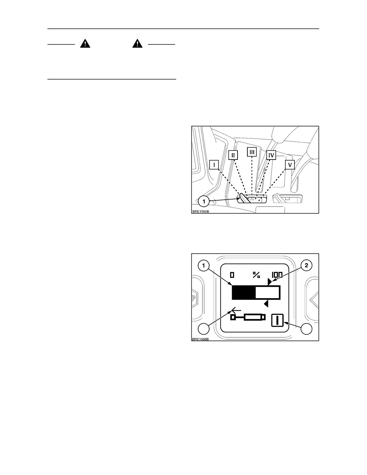
Each control lever has a ’rolling gate’ which is used
to select or lock--out individual remote valve
functions. Detents on the lever (1) will lock the ’gate’
in one of five positions.
I.
Neutral and Raise locked out: Lower and Float
functional. Move the lever into float before
selecting this position.
II. Raise detent locked out: Neutral, Lower and
Float functions operative.
III. All valve functions are operative.
IV. Float locked out: Raise, Neutral and Lower
122
functional.
V. Lever locked in neutral: No valve functions are
available.
Visual Displays
Depress the remote valve key on the keypad and the
following information will be displayed in the DMD for
each valve:
1. Momentary oil flow from the valve. The shaded
area represents the percentage of oil flow, this
will change as the flow increases or decreases.
2. Maximum flow rate (%) as set by the operator.
The extend/retract directional arrows represent
4
3
the maximum flow setting.
123
3. Number of the remote valve in operation.
4. Direction of cylinder movement, extend (Raise)
or retract (Lower). The direction of cylinder travel
is identified by the arrow.
3--70
SECTION 3 -- FIELD OPERATION
Setting the Maximum Flow Rate
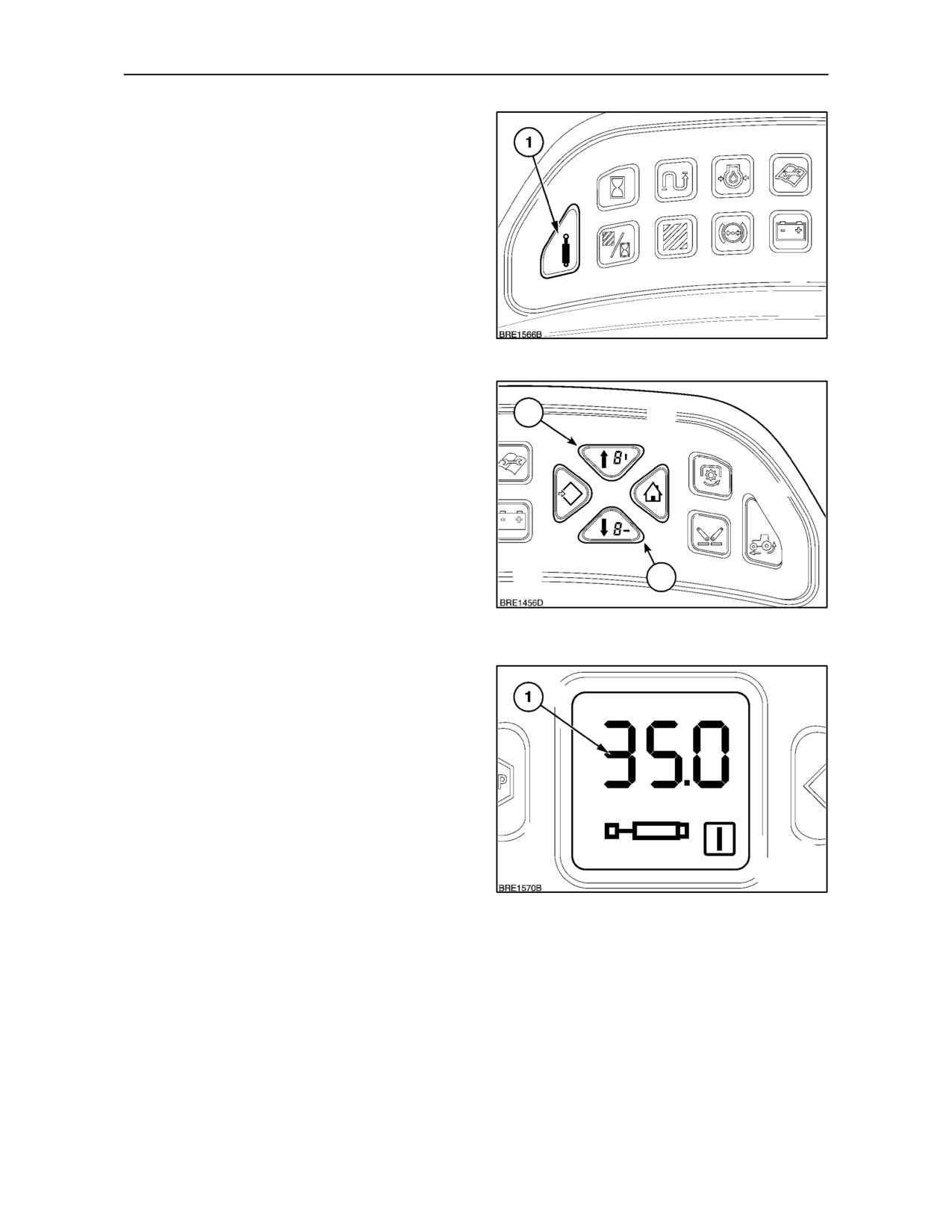
The maximum flow rate for each remote valve can be
set using the menu keys on the Enhanced keypad.
To adjust the remote valve flow rate, the key--start
must be switched ON.
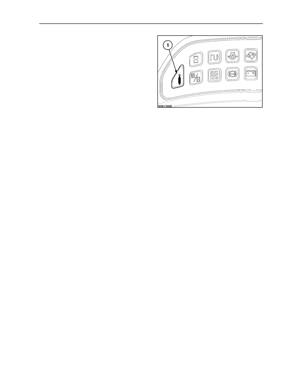
Using the remote valve key
(1), select the
appropriate valve (1, 2, 3, or 4).
124
With the selected valve number displayed in the
DMD, Use the MENU UP/DOWN keys (1 and 2), to
1
increase or decrease the maximum flow rate of the
selected valve. The flow rate will be stored in the
tractor control module until re--programmed, turning
the key--start off will not erase the setting.
NOTE: The remote valve flow rate setting (1),
Figure 126, will apply to both extend and retract
movements of the cylinder.
IMPORTANT: During remote valve set--up, a pause
2
of more than two seconds in key operation will exit
set--up and return to the previous setting, re--enter
125
set--up mode again to continue.
126
3--71
SECTION 3 -- FIELD OPERATION
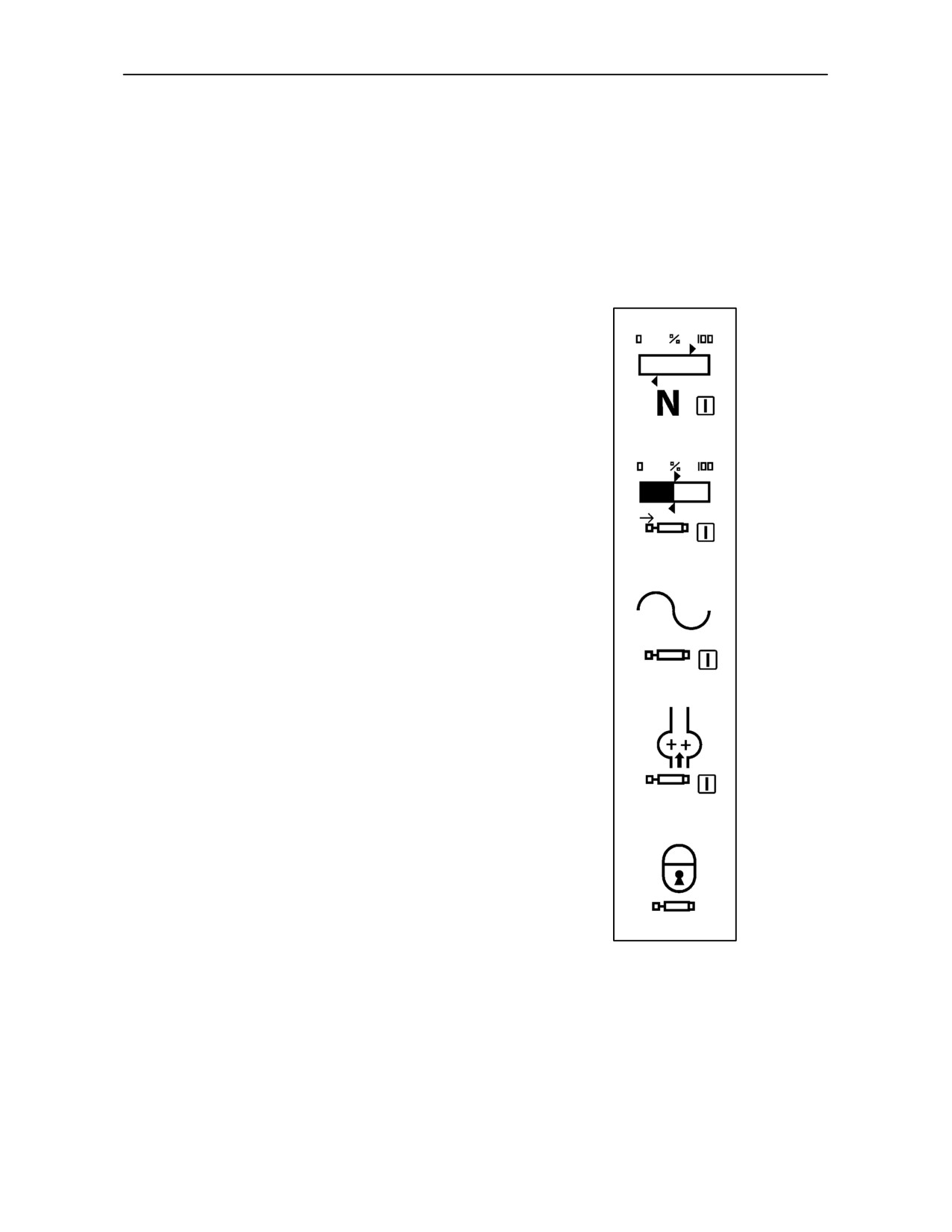
Additional Displays
As each of the electro--hydraulic remote valve
functions are selected, a corresponding visual
display will appear in the Dot Matrix Screen.
NOTE: The following illustrations relate to remote
valve number 1, see page 3--70 for details on remote
valve numbering.
1. Remote valve in neutral position.
2. Remote valve operating at maximum flow set
by the operator. The illustration shows cylinder
operating in retract mode.
3. Remote valve lever in ’float’ position.
4. Remote valve locked in hydraulic motor mode.
Retract and Float positions only available.
5. Electro--Hydraulic Remote Valve system
switched OFF. All valve functions
de--activated.
3--72
SECTION 3 -- FIELD OPERATION
Manual and Programmable Lever Operation
The Enhanced keypad is used to select and
programme the timed functions for each of the
electro--hydraulic remote valves. As each remote
valve is selected using the remote valve key (1), a
visual display of the valve functions will appear in the
Dot Matrix screen.
Depress the key once to activate the remote valve
display in the DMD. Repeated operation of the key
will cycle through each valve display individually.
127
Manual Operation
When used in manual mode, without the timer
function, the electronic remote valves will operate in
a similar way to the mechanical valves previously
described.
IMPORTANT:Care must be taken when operating in
the manual mode that the remote valve lever is not
left in the detented extend or retract positions when
using remote cylinders. When the cylinder has
reached the end of its stroke the control lever must
be returned to the neutral position manually. Failure
to observe this procedure will overheat the oil and
may lead to failure of hydraulic or driveline
components.
IMPORTANT: Never use the neutral position from
the extend or retract position to stop a hydraulic
motor. Sudden hydraulic lock up of the system may
cause extensive damage to the motor.
In manual mode, oil flow through each valve is
adjusted using the flow rate setting as previously
described.
3--73
SECTION 3 -- FIELD OPERATION
Timed Programme Operation
Timed programme operation is provided primarily for
operation of hydraulic cylinders. This feature allows
the operator to programme a time delay between
when the control levers are activated and when the
oil flow to the implement is stopped.
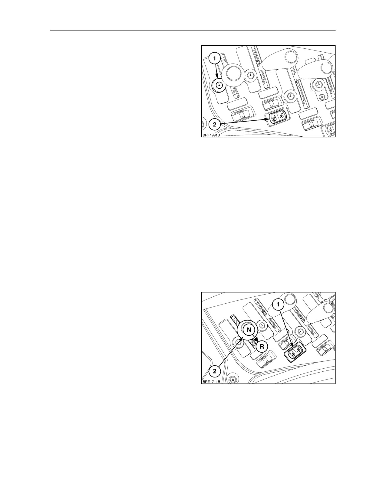
To operate the electronic remote valves in
programmed mode, depress the appropriate side of
timer control switch (2) as shown. When the switch
is depressed, the green light (1) adjacent to the
remote valve lever will start to flash. The system is
now in standby mode ready to accept a programme
128
sequence. The light will continue to flash for ten
seconds allowing the operator sufficient time to begin
the programming sequence. If a programme is not
started within this period, the system will
automatically de--activate, depress the timer control
switch again to re--start the sequence.
Programming a Double Acting Service
To programme the remote valves, first ensure the
cylinder hydraulic hoses are properly connected to
the appropriate rear remote valve. Start the tractor
engine and set at the normal operating speed in
which the cylinder is to be operated. This is important
as the programming of the control levers is based on
a time interval corresponding to the time it takes the
cylinder rod to extend and retract. Any change in
engine rpm will have an effect on hydraulic flow and
therefore the time taken for the cylinder to extend
and retract.
The timed period for control lever operation remains
the same regardless of oil flow, therefore consistent
operation is required for the system to function
correctly. Using the corresponding timer switch (1)
depress the switch so the light begins to flash. While
the light is flashing move control lever (2) to extend
the cylinder (R). At this point the light ceases to flash
and will remain on.
Hold the lever until the cylinder is extended to the
desired position and then return the lever to the
neutral position. When the lever is returned to the
neutral position the programming light will begin to
flash again indicating the retract phase of the cycle
should now be programmed.
129
3--74
SECTION 3 -- FIELD OPERATION
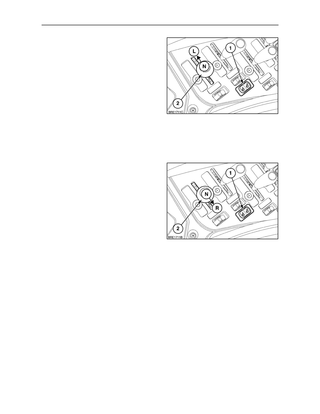
Operate the control lever (2) to retract the cylinder
(L), and the programming light will cease to flash and
remain on. Hold the lever until the cylinder has
completed the retract cycle and then return to the
neutral position. After the second phase has been
programmed the light will remain on.
After the second phase has been completed and the
lever has been returned to neutral, the programme
will be automatically stored.
Repeat the above sequence to programme the
remaining control levers if required.
130
Programming of the control lever can be performed
in either sequence, extend/retract, retract/extend or
for one movement only, extend or retract. The
maximum allowable time span for any timed
operation is 30 seconds.
Programming a Single Acting Service
To programme a single acting service carry out the
same set--up procedure as previously described for
a double acting service.
With the programme light flashing, move the remote
valve lever from neutral to the extend position (R).
When the cylinder has extended to the desired
position, manually return the lever to the neutral
position. To store the setting, depress the timer
switch. In single acting mode the sequence will NOT
be automatically stored.
131
A single acting service can be programmed to
operate in either extend or retract modes.
NOTE: When using a timed sequence for a single
acting service i.e. programmed in extend mode only,
the retract mode will not function until the programme
sequence has been deleted.
If the control lever is moved to the float position no
timed programme is possible and the control lever
must be returned to neutral manually.
3--75
SECTION 3 -- FIELD OPERATION
Setting Remote Valve Priority
A remote valve with oil flow priority will always take
precedence over other remote valves for hydraulic oil
flow. Irrespective of flow demand by the other valves,
the priority valve will always maintain a constant
output.
For implements requiring multiple remote valve
services, there may be a need for one of the valves
to have oil flow priority, i.e. to provide oil flow for a
hydraulic motor.
With Electro--Hydraulic remote valves, the operator
132
can select one remote valve as the priority valve.
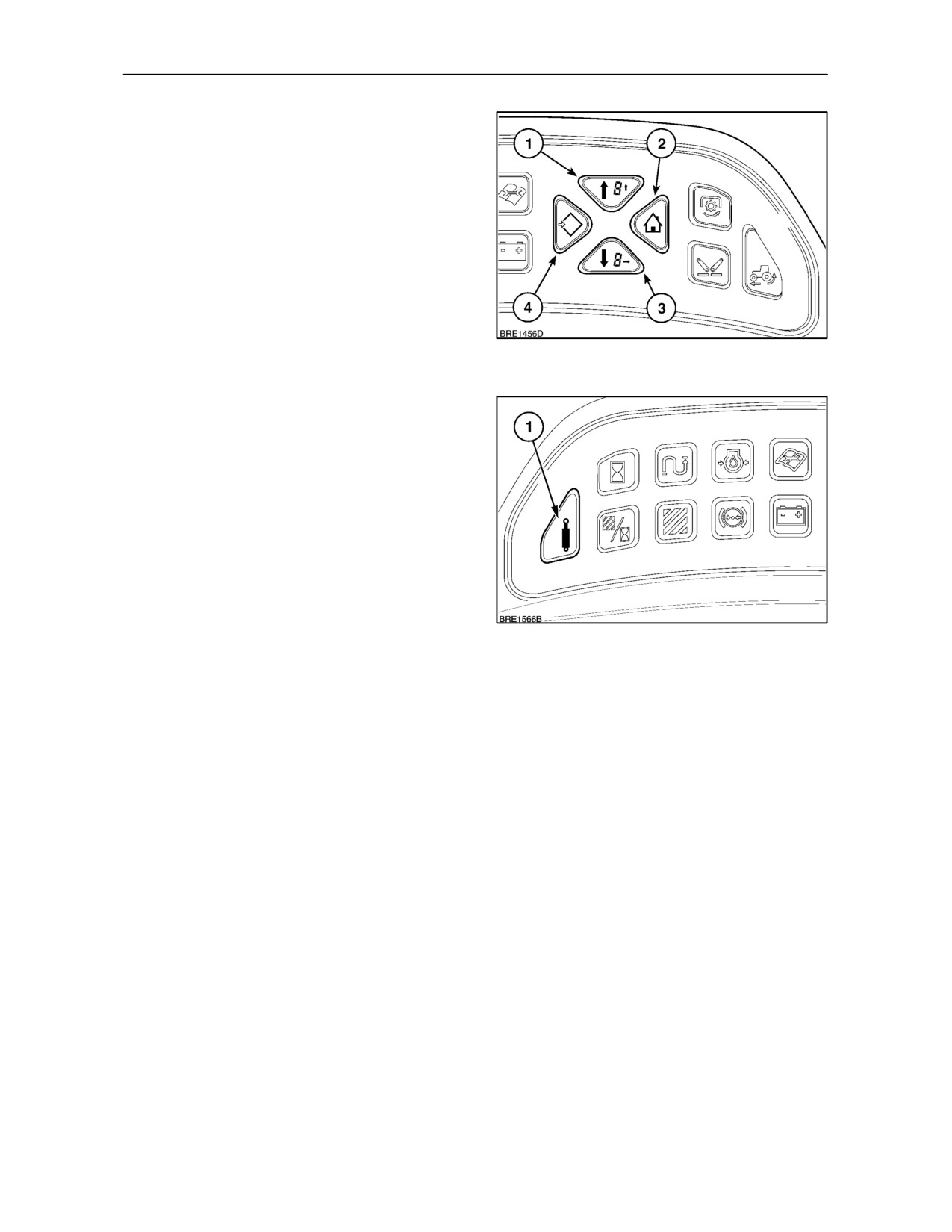
• With the key--start in the ON position, depress
and hold the Menu/Enter key (4) Figure 132, until
the central LCD display reads Ehrx (where ’x’ is
the current priority valve number).
NOTE: If a dash (- ) appears in the display, the
remote valves are not prioritised.
• After a few seconds the LCD display will change
to read PEhr.
• Momentarily depress the EHR remote valve key
(1) Figure 133, to select the valve required for
prioritisation. Depressing the key repeatedly will
133
scroll through the valve numbers.
• When the desired valve number is shown in the
display, depress the Exit/Cancel key
(2)
Figure 132, to exit set--up and return to the
previous display. The valve priority setting is now
memorised.
3--76
SECTION 3 -- FIELD OPERATION
Replaying a Timed Programme
Relieving System Pressure
The timed sequence begins as soon as the lever is
WARNING
placed in the extend or retract detent position. On
reaching the end of the timed period, oil flowing
Before connecting or disconnecting hydraulic hoses
through the remote valve will be halted, the remote
at the remote cylinders, relieve the pressure in the
valve lever should now be returned to the neutral
circuit by first starting the engine and then move the
position ready for the next operation. Throughout the
control levers fully forward to the “float” position.
replay sequence, the green warning light will remain
Then stop the engine. Make sure no one will be
illuminated.
injured by moving equipment when relieving
pressure in the system. Before disconnecting
cylinders or equipment, make sure the equipment or
Deleting Programmes
implement is supported securely.
Never work under equipment supported by a
To delete a programme, depress the programme
hydraulic device because it may drop if the control is
switch to de--activate timer operation. The light will
actuated (even with the engine stopped) or in the
extinguish and the memorised sequence will be
event of hose failure, etc. always use a secure
cleared from the programme in the memory.
support for equipment which must be serviced while
in the raised position. Make sure that oil contained
Recalling a Stored Programme
within the remote cylinders is clean and is of the
correct grade.
With the key--start on and all remote valve levers in
neutral, hold down the timer switch for the EHR
required. Keep the timer switch depressed until the
light illuminates and remains on, the previously
stored timer sequence is now re--activated.
IMPORTANT: At key--off (engine stop), electronic
programme settings made during tractor operation
are transferred from the operating memory to the
main memory. To provide sufficient time for the data
to transfer, allow a minimum of five seconds delay
before turning the key on again.
3--77
SECTION 3 -- FIELD OPERATION
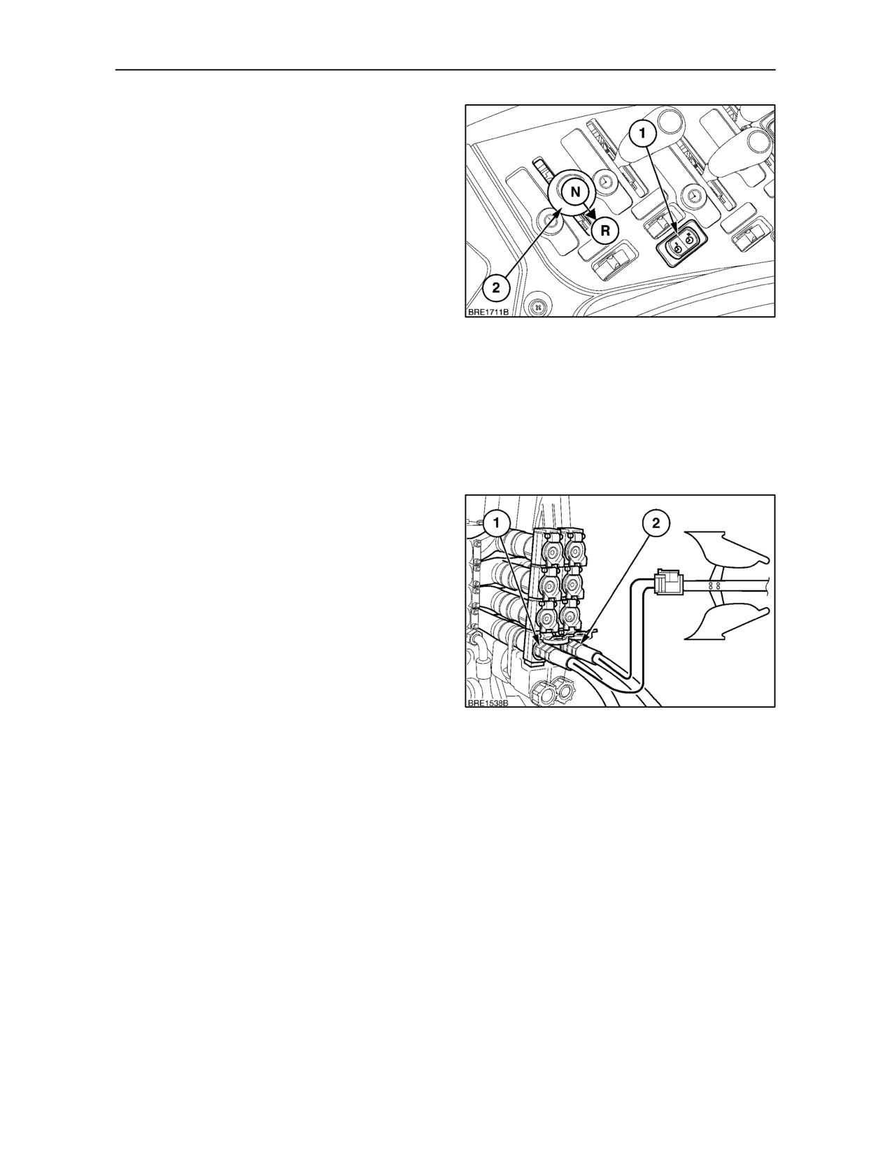
Connecting Single-Acting Cylinders
Connect the hose from a single-acting cylinder to the
extend (left--hand) coupler on the remote control
valve, as previously described.
To extend a single-acting cylinder, pull the control
lever back to the extend position (R).
Manually return the lever to the neutral position to
stop the cylinder when it has reached the desired
position.
(see page 3--75).
To retract a single-acting cylinder, move the lever
fully forward to the float (F) position.
134
NOTE: In single acting timer mode the remote lever
will lock in the extend position and will not
automatically return to the neutral position.
IMPORTANT: Always use the “float” position to
lower a single-acting cylinder. The “retract” position
is for double-acting cylinders only.
Connecting Double-Acting Cylinders
Connect the feed hose from a double-acting cylinder
to the left--hand coupler (1) on the remote control
valve and the return hose to the right--hand coupler
(2), as previously described. To extend a double-act-
ing cylinder, pull the control lever back to the extend
position.
To retract a double-acting cylinder, push the control
lever forward past neutral to the retract position.
Further forward movement of the lever will select
float which will allow the cylinder to extend or retract
freely. This feature is very helpful when carrying out
135
work with equipment such as scraper blades and
loaders.
NOTE: To prevent cylinders creeping under load,
always connect the hose from the load supporting
side of the cylinder to the left--hand coupler.
3--78

SECTION 3 -- FIELD OPERATION
Operating Continuous Flow Hydraulic
Equipment
Continuous flow hydraulic equipment (e.g., hydraulic
motors) should be connected to the lower (1st)
remote control valve couplers with the pressure hose
connected to the right--hand coupler and the return
hose connected to the low pressure return circuit
(see page 3--81, ’Return Oil Line’).
The oil flow should be adjusted to regulate the motor
speed. If the flow is too high, the 3-point hitch and
other remote valves may slow down or stop.
Controlling the flow in this way will ensure that the
hydraulic system will only supply the oil required by
the motor.
With the remote control valve lever fully forward in
the float (F) position, the motor will be stationary. The
hydraulic motor will operate if the lever is pulled back
to the retract position (Lower). To stop the motor,
move the lever from the lower position to the float
position. In the float position the motor will be able to
stop slowly, which will not damage the motor.
IMPORTANT: When operating continuous flow
equipment, the remote control valve lever must not
be moved rearward to the neutral (N) or raise (R)
positions as damage to the equipment may result.
Select position 1 on the rolling gate to lock out the
neutral and extend services (see page 3--70)
136
Observe the following to further protect the tractor
and equipment.
• Do not open any bypass valve in the equipment
or motor. Adjust the oil flow through the valve to
regulate the rate of flow or speed of the motor.
• To ensure optimum hydraulic oil cooling, operate
continuous flow equipment at the highest flow
setting and lowest engine speed that will give the
required machine performance and speed.
3--79
SECTION 3 -- FIELD OPERATION
Operating Several Remote Valves
Simultaneously or Remote Valves and
1
Hydraulic Lift Simultaneously
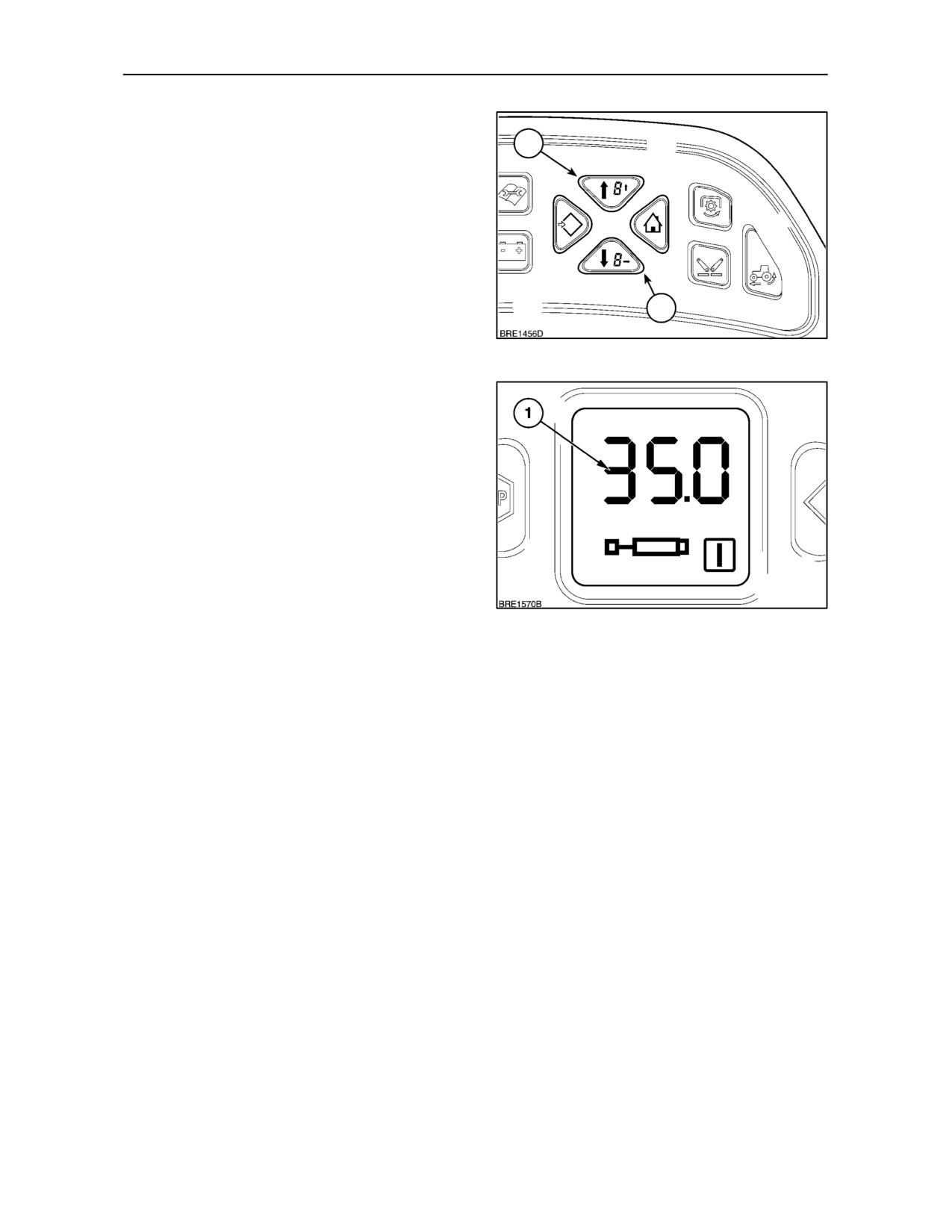
If operating two or more remote control valves
simultaneously or remote valves and the hydraulic
lift, the flow through the valves should be adjusted
using the enhanced keypad to provide a partial flow,
as previously described. If not so adjusted, all the
available flow may be directed to the full flow circuit
when the pressure in that circuit is less than that of
the other circuits in use.
2
NOTE: The oil flow (1), Figure 138, through remote
137
valve number one (lower valve) will always take
priority over the other valves. For equipment using
more than one remote valve, the hydraulic service
with the highest priority should be connected to valve
number one.
138
Bleeding Remote Cylinders
When connecting a cylinder with trapped air, i.e., a
new cylinder, one that has been out of service or one
that has had the hoses disconnected, it will be
necessary to bleed the cylinder to remove the air.
With the hoses connected to the remote control valve
couplers at the rear of the tractor, position the
cylinder with the hose end uppermost and extend
and retract the cylinder seven or eight times using the
remote control valve operating lever.
Check the rear axle oil level before and after
operating a remote cylinder.
3--80
SECTION 3 -- FIELD OPERATION
ADDITIONAL OIL SUPPLY FOR REMOTE
HYDRAULIC SERVICES
2
(Power Beyond Port, where fitted)
For implements or attachments requiring continuous
or high oil flows from the tractor hydraulic system,
provision is made to connect directly into the main
hydraulic circuit at the rear of the tractor.
To operate correctly the implement must be fitted
with a variable flow hydraulic system that will,
1
through a sensing line, control oil flow from the main
tractor hydraulic pump.
139
IMPORTANT: Before attempting to remove any
blanking plugs or attach pipework, switch OFF the
engine and ensure the areas around the plugs and
pipe connections are thoroughly clean to prevent
contamination of the tractor hydraulic system.
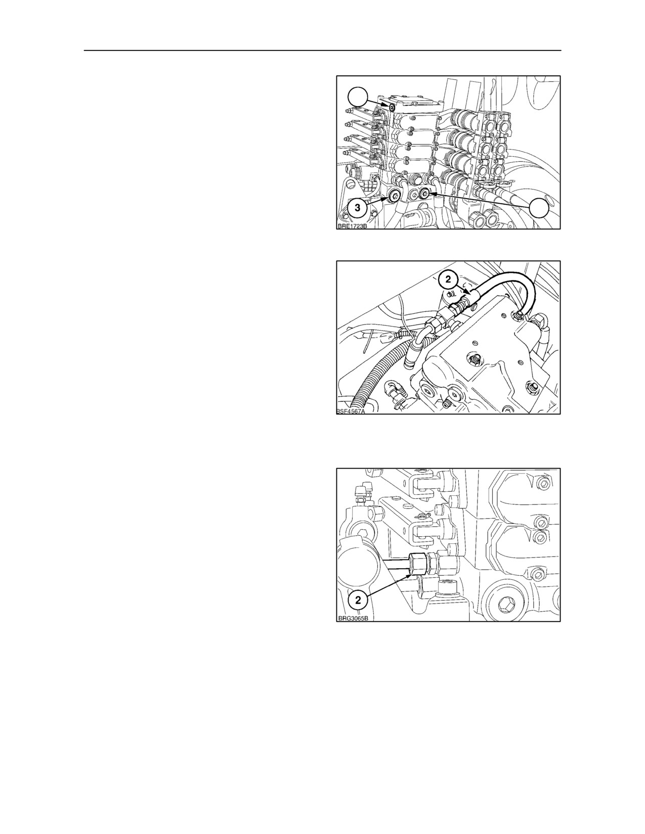
P -- Pressure Line (1)
To connect the implement pressure line, remove the
plug (1) from the external services ’power beyond’
port below the remote valve manifold. Using a
suitable connector, M22 x
1.5/15.5
(ISO 6149),
attach the implement supply line to this port. With the
implement control valve in neutral, a low standby
pressure of 21 to 24 bar (305 to 348 lbf. in.) will be
140
maintained in the pressure line connected to this
port.
LS -- Load Sensing (LS) Line (2)
Connect the sensing line from the M12 x 1.5/11.5
(ISO 6149) port (2), to the implement control valve.
It isthesensinglinewhichgeneratesandcontrolsthe
oil pressure and flow from the tractor hydraulic pump.
When an implement control valve is operated, the
low standby pressure from port ’P’, is diverted down
the sensing line to ’switch on’ the tractor hydraulic
pump. In operation, the load sensing line constantly
monitors pressure and flow to ensure supply never
exceeds demand.
LS Port Location (2)
141
1. Figure 139, with mechanically operated remote
valves and Electronic Draft Control.
2. Figure 140, with electronically operated remote
valves and Electronic Draft Control.
3. Figure 141, with mechanically operated remote
valves and Mechanical Draft Control.
3--81
SECTION 3 -- FIELD OPERATION
To connect the load sensing line from the implement
in Figures 140 and 141, a ’T’ piece will need to be
inserted in to the hydraulic line. Consult your
authorised dealer.
IMPORTANT: To ensure correct operation of the
system, the implement control valve, when in
neutral, must be capable of directing the pressure
from the sensing line back to sump through the return
line (3) to the tractor. The hydraulic system will then
return to the low pressure standby mode.
R -- Return Oil Line (3)
The return oil line from the implement control valves
should be connected to the M27 x 2/19 (ISO 6149)
port (3). This will permit the oil to return directly back
into the tractor hydraulic system.
NOTE: Ensure the hoses have a suitable capacity to
accomodate the required oil flow, and that both the
sensing line and hoses are sufficiently long enough
to allow for implement movement or articulation
when in work.
3--82
SECTION 3 -- FIELD OPERATION
THREE-POINT LINKAGE
IMPORTANT: Before transporting or operating
equipment, ensure that the flexible link ends (where
fitted) are locked in the operating position.
ATTACHING 3-POINT EQUIPMENT
1. With the engine stopped and parking brake
NOTE: Before attaching equipment, adjust lift rods
engaged, adjust the top link until the implement
and select the correct top link hole for the implement
mast pin can be inserted through the mast and
and work to be carried out.
top link. Ensure sufficient thread remains in the
adjuster tube to prevent the threaded ends from
Ensure that the telescopic stabilisers are installed
pulling out under load.
and correctly adjusted. Remove the swinging
drawbar if close-mounted equipment is being
2. Connect remote equipment, where applicable.
attached.
3. After attaching implement and before actual
IMPORTANT: Always select Position Control when
operation check that:
attaching equipment, transporting equipment, when
no equipment is attached or at any time when not
• No interference occurs with tractor components.
operating in Draft Control. With Mechanical Lower
Link Sensing hydraulics, set the Draft Control lever
• The top link does not contact the PTO guard with
fully forward. With Electronic Draft Control, turn the
the implement at its lowest position.
Position/Draft sensitivity knob fully anti-clockwise
IMPORTANT: Before operating PTO driven
Most equipment can be attached to your tractor as
equipment, check to make sure that the PTO
follows:
driveline will not over-extend so as to become
disengaged, bottom out or be at an excessive angle.
1. Position the tractor so that the lower link hitch
Ensure that the driveline shield does not contact the
points are level with and slightly ahead of the
PTO guard or drawbar. See ‘Attaching P.T.O.
implement hitch pins. Carefully inch the tractor
Driven Equipment’.
rearwards to align the tractor and implement
hitch points.
IMPORTANT: When attaching mounted or
semi-mounted equipment to the 3-point linkage or
2. Attach the implement to the lower links, as
when attaching trailed equipment to the drawbar or
described in ‘FLEXIBLE LINK ENDS’ on page
hitch, ensure that there is adequate clearance
3--89 or ‘QUICK HITCH’ on page 3--90.
between the implement and the tractor.
Semi-mounted or trailed equipment may interfere
WARNING
with the tractor rear tyres. If necessary, adjust
Engage the parking brake before leaving the tractor
steering stops (four wheel drive only) or stabilisers.
to make the connections. It is essential to have the
engine running to operate the external lift controls
when making lower link connections. If your tractor
does not have these switches or when making other
connections, stop the engine.
3--83
SECTION 3 -- FIELD OPERATION
Implement to Cab/Platform Clearance
• Set the lift rods in the front hole in the lower links.
This will reduce the lift height (dependent upon
the lift rod length).
WARNING
Some mounted and semi-mounted equipment may
• Lengthen the lift rods.
interfere with and damage the cab or platform. You
may be injured by broken glass or the cab ROPS may
be damaged if equipment interferes with the cab or
• Connect the top link to the upper hole in the top
platform.
link attachment bracket and use the lowest
possible equipment mast hole.
To prevent tractor damage, proceed as follows:
• Make only the minimum adjustments required to
clear the cab. If equipment performance is
• Attach the equipment as outlined previously.
unsatisfactory, it may be necessary to modify the
equipment, consult your authorised dealer.
• Check for adequate clearance by slowly raising
the equipment with the lift control lever in
Removing Equipment
Position Control. If any part of the equipment
comes closer than 100 mm (4 in.) to the cab,
When removing equipment, the procedure is the
adopt one of the following options:
reverse of attaching. The following information will
make disconnection easier and safer.
If your tractor has Mechanical Lower Link Sensing
hydraulics, adjust the height limiter cam to prevent
• Always park the equipment on a firm, level
excessive lift. If your tractor is equipped with
surface.
Electronic Draft Control, adjust the height limit
control knob to limit upward movement.
• Support equipment so that it will not tip or fall
when detached from the tractor.
If Draft Control is needed or if insufficient ground
clearance is obtained with adequate cab clearance,
• Always relieve all hydraulic pressure in remote
you can adjust the lift linkage, open the cab rear
cylinders by selecting the float position before
window, or modify the equipment to clear the cab.
disconnecting.
Linkage adjustments, while increasing cab
clearance, may have an adverse effect on the
When attaching mounted equipment to the
implement operating characteristics
three-point linkage, the following adjustments may
be made to ensure satisfactory operation:
3--84
SECTION 3 -- FIELD OPERATION
LIFT RODS, LOWER LINKS AND TOP LINK
Lower Links and Lift Rod Adjustment
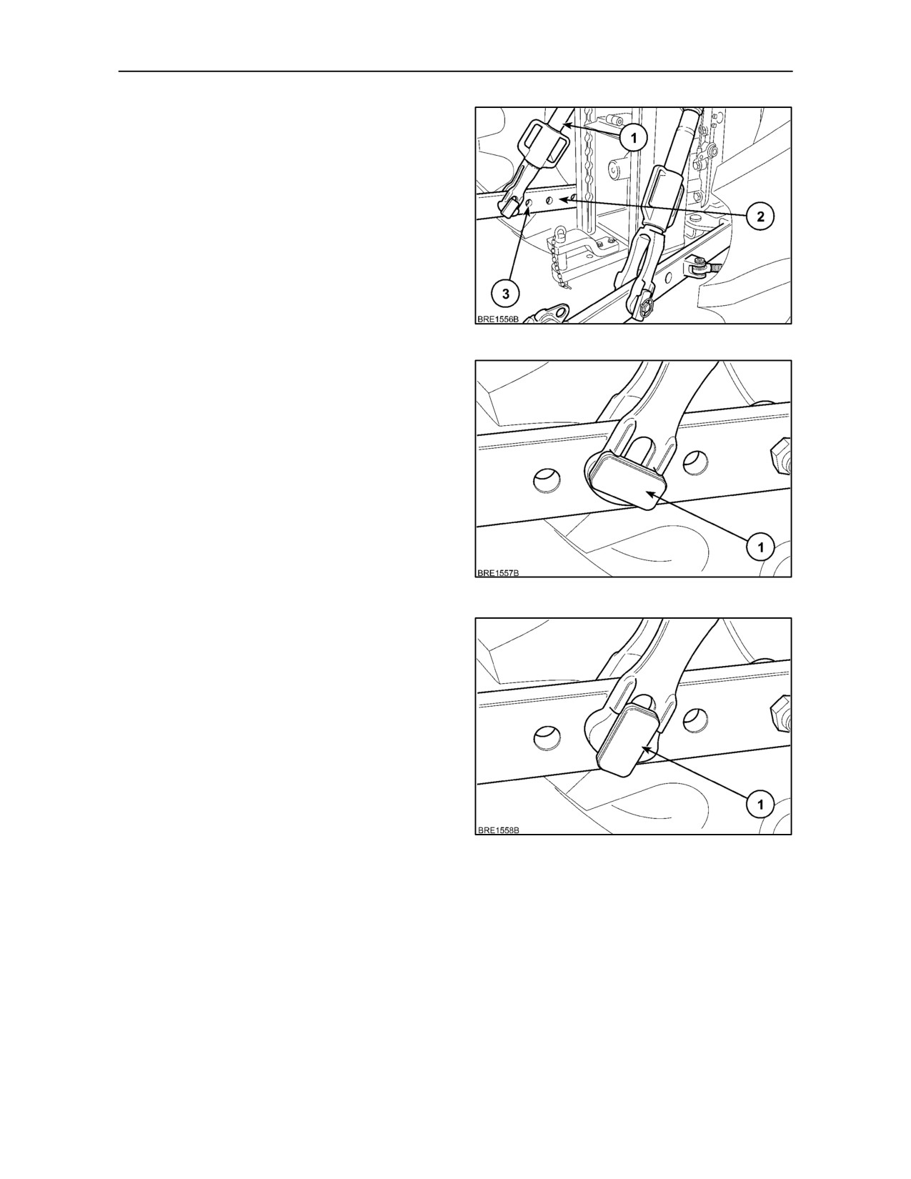
Each lower link (3) has three holes for attachment of
the lift rods. When the tractor leaves the factory, the
lift rods (1) are connected to the rear hole in each
lower link to give maximum lift capacity. If required,
attach the lift rods to the front hole (nearest the
tractor) for maximum lift height. The centre hole
offers a compromise between the optimum lift height
and lift capacity.
142
Both left and right-hand lift rods have a slot at the
lower end which is used to provide a limited amount
of float on the lower link arms. For normal operation
the rectangular plate on the securing pin (1) is
positioned so the lift arm remains fixed in relation to
the lower link arm.
143
If the securing pin (1) is rotated through 90° as
shown, this will allow an implement limited vertical
movement independent of the tractor which is a
useful feature for the operation of wide implements.
After carrying out the adjustment ensure the outer
retaining plate and spring clip are replaced and
securely locked.
Before disconnecting a lift rod from the lower link,
lower attached equipment to the ground, apply the
handbrake and stop the engine. Prior to removing the
securing pin ensure that attached equipment is
correctly supported and that no residual pressure
remains in the hydraulic system.
144
Move the hydraulic lift control lever backwards and
forwards several times, in order to remove residual
pressure, then move the lever fully forward.
With electronic draft control
(EDC) move the
hydraulic lift control lever to the fully lowered position
before switching off the engine.
3--85
SECTION 3 -- FIELD OPERATION
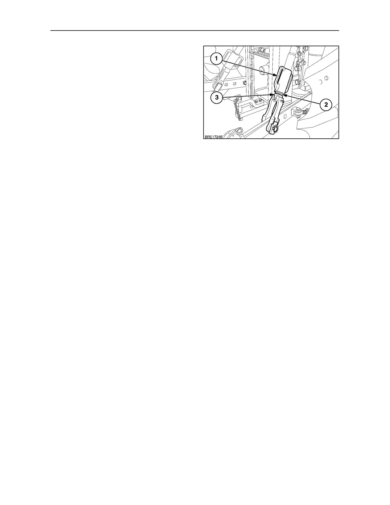
To increase or decrease lift rod length, rotate the
upper part of the lift rod by means of the handles on
the turnbuckle (1).
Before the turnbuckle can be rotated, it is necessary
to lift the turnbuckleto disengagethe slot (2) fromthe
lug (3) on the lower section of the lift rod. Rotate the
turnbuckle to lengthen or shorten the lift rod
assembly.
When adjustment is satisfactory, allow the
turnbuckle to lower into position. Ensure that the
turnbuckle is fully down and that the slot engages
with the lug to prevent unintentional rotation.
145
IMPORTANT: When attaching mounted or
semi-mounted equipment to the 3-point linkage or
when coupling trailed equipment to the drawbar or
automatic pick-up hitch, ensure that there is
adequate clearance between the implement and the
cab or rear window in any open position.
3--86
SECTION 3 -- FIELD OPERATION
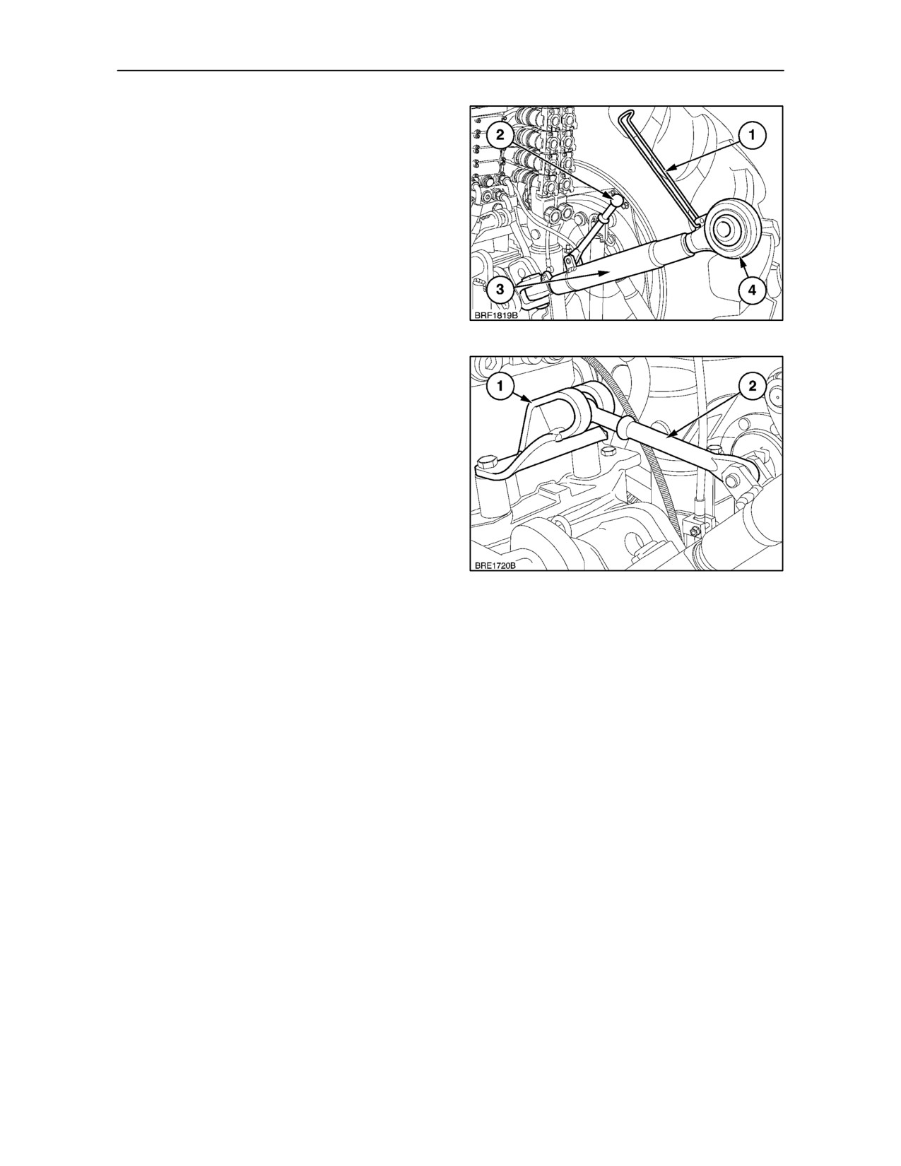
Top Link
The top link has a threaded centre section (3) , which,
when rotated, will shorten or lengthen the top link, as
required. Lift up the spring retainer (1) to allow the
centre section (3) to rotate. To ease adjustment, lift
the handle (2) and use it as a lever. Alternatively,
rotating the link end (4) will permit limited adjustment
of top link length.
To lock the sleeve after adjustment, push the spring
retainer down so that it holds the handle flush against
the sleeve.
146
When not in use, the top link can be removed and
stored or left in an upright position. Hook the ball end
of the handle (2), into the bracket (1) on the rear axle
housing, as shown.
147
3--87
SECTION 3 -- FIELD OPERATION
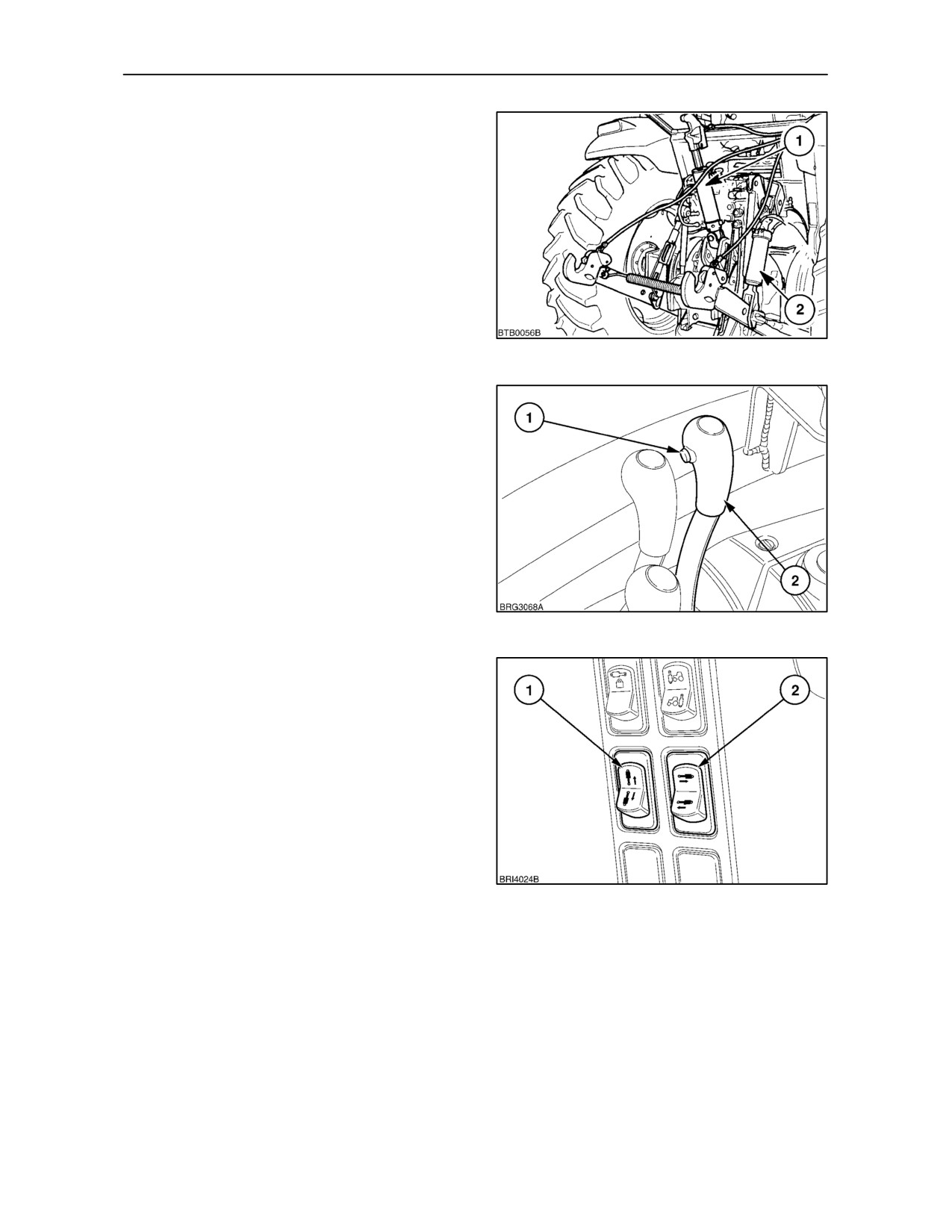
TOP LINK AND RIGHT-HAND LIFT ROD
(hydraulic adjust)
The hydraulic adjust top link
(1) is available in
conjunction with a hydraulic adjust right-hand lift rod
(2). Both the top link and the lift rod incorporate a
double--acting ram cylinder connected into No. IIII
remote control valve.
148
With Electro--Mechanical Operation
To lengthen the right-hand lift rod and move the lower
link downwards, pull No. IIII remote control valve
lever (2) towards you. Push the lever away from you,
past the neutral position to retract the cylinder and
shorten the right-hand lift rod.
To lengthen the top link, depress and hold in the
button (1) on No. IIII remote control valve lever (2)
and pull the lever towards you. Push the lever away
from you, past the neutral position to retract the
cylinder and shorten the top link assembly.
149
With Electronic Operation
Two switches located on the cab ’C’ pillar operate the
hydraulic top link and right--hand lift rod. Both
switches are spring centered and will return to the
neutral position when released.
Depress and hold the top of the left--hand switch (1)
to retract the top link, depress the bottom of the
switch to extend the link.
Depressing the top of the right--hand switch (2) will
retract the hydraulic cylinder and raise the link arm,
depress the bottom of the switch to extend the
150
cylinder and lower the link arm.
Automatic check valves on the top link and lift rod
cylinders will prevent them from ’creeping’.
3--88
SECTION 3 -- FIELD OPERATION
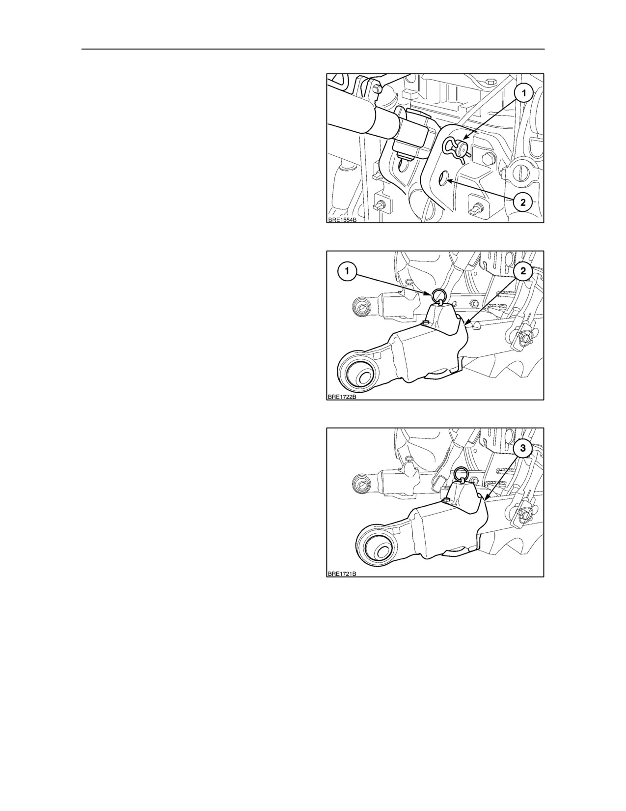
TOP LINK BRACKET
(Lower Link Sensing hydraulics only)
Draft loads are sensed by the lower links, therefore
the top link is attached to a bracket rigidly fixed to the
rear axle housing.
Two holes are provided in the bracket for attachment
of the top link. Insert the pin (1) through the upper
hole, as shown, for maximum lift capacity and the
greatest implement to cab clearance. Use the lower
hole (2) for the best ground penetration and greatest
implement to ground clearance (when the implement
is raised).
151
FLEXIBLE LINK ENDS (where fitted)
Pull the levers (1) up to release the link ends. With the
link ends released, connection to the implement will
be easier. The link end (2) is shown in the extended
position. The link end (3) is shown in the closed
(operating) position.
With both link ends extended, connect the link ends
to the equipment and secure with linchpins. Start the
engine and carefully inch the tractor rearwards until
both flexible link ends lock in the operating (closed)
position (3). Stop the engine and engage the parking
brake.
152
Attach the top link.
IMPORTANT: Before transporting or operating the
equipment, make sure the flexible link ends are
locked in the operating position. Remove the
drawbar if it interferes with close-mounted
equipment.
153
3--89
SECTION 3 -- FIELD OPERATION
QUICK HITCH
(where fitted)
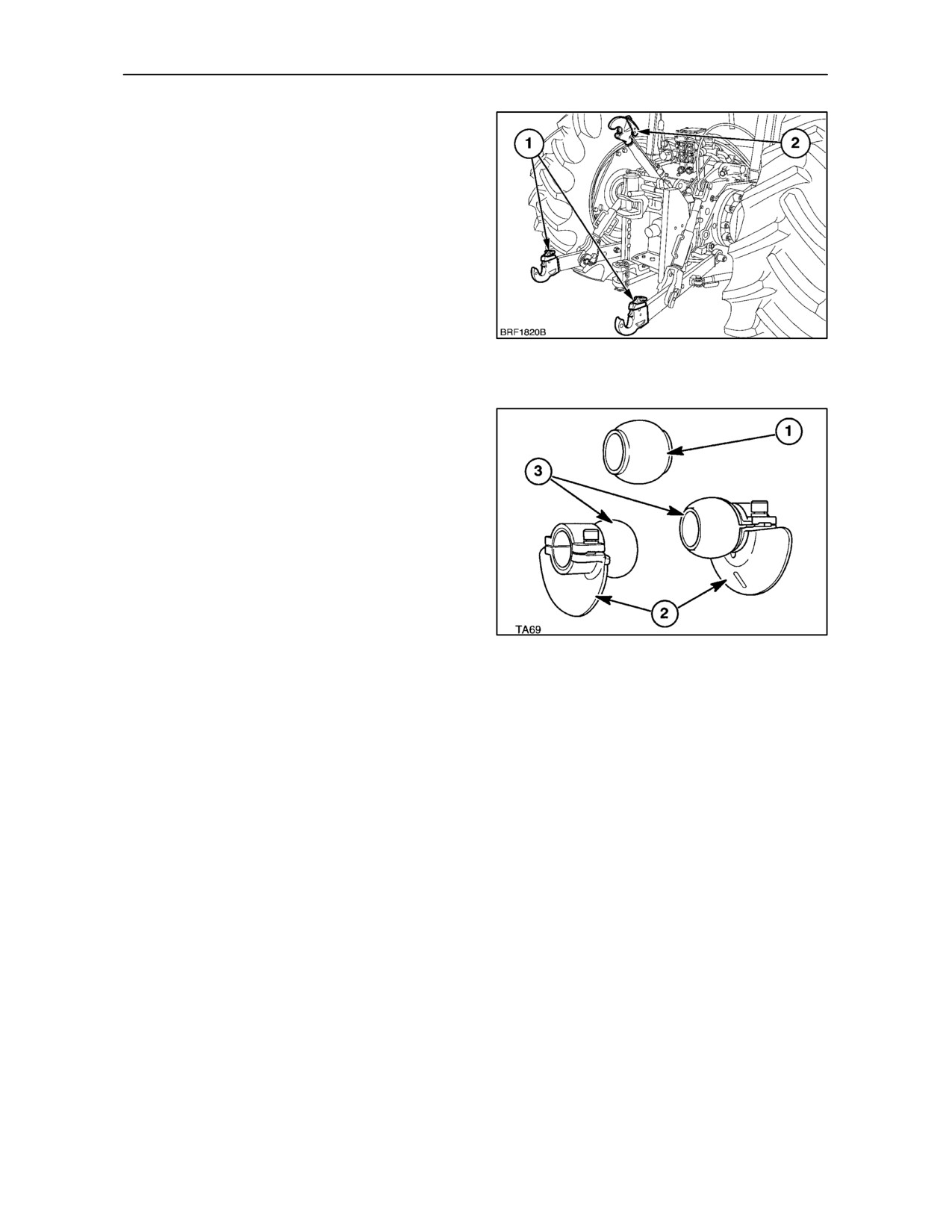
The quick hitch consists of an alternative pair of lower
links (1) and an adjustable top link (2). The lower links
and the top link have open claw ends that permit
rapid coupling and uncoupling of implements without
leaving the cab. The claws are equipped with
self-locking latches to ensure positive retention of
the tractor linkage to the implement. Cables are
provided for attachment to the latches.
An adjustable spacer spring is available as an
accessory. The spring maintains the lower links at
154
the width setting required to match that of the
implement.
Three ball-bushings are supplied for installation on the
implement, if required. The ball-bushing with projecting
lips (1) should be installed on the implement upper
hitch pin. The two plain ball-bushings (3) with their
detachable guides
(2) should be installed on the
implement lower hitch pins.
155
Coupling Implement to Tractor
Adjust the stabilisers to maintain the tractor lower links
at the correct distance apart so they align with the
ball-bushings installed on the implement lower hitch
pins. Alternatively, use the optional, adjustable spacer,
if available. The spacer consists of a closed spring, with
a rod screwed into one end. To adjust, remove the ‘R’
clip and disconnect the spacer rod from the bracket on
the right-hand lower link. Screw the rod into or out of
the spring to shorten or lengthen the assembly.
3--90
SECTION 3 -- FIELD OPERATION
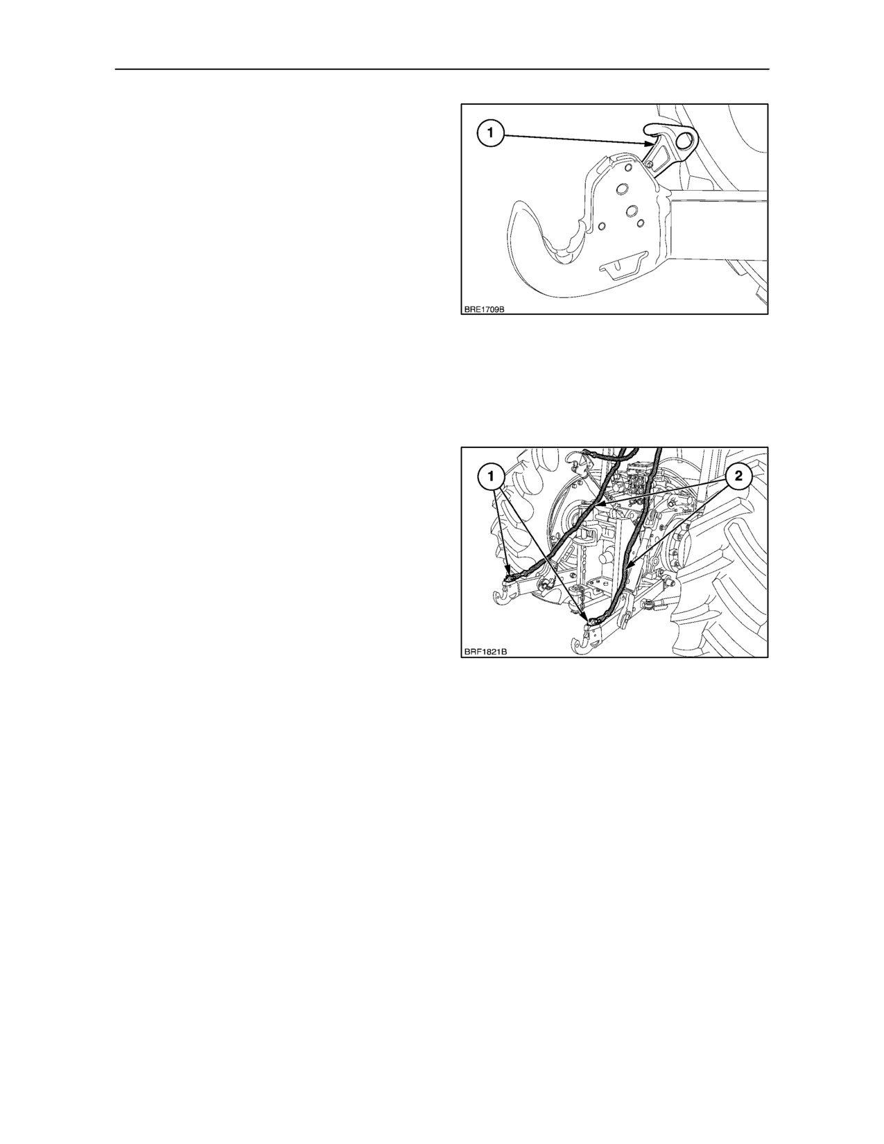
Place the top link in the transport position. With the
lower links fully lowered and the self-locking latches
(1) in the open position as shown, reverse the tractor
until the lower link claw couplers are beneath the
implement hitch pins. The combination of large claw
openings and the guides on the implement
ball-bushes make accurate alignment of tractor to
implement unnecessary.
Raise the lower links using the hydraulic lift lever until
the claw couplers engage the ball-bushes. An
audible click will be heard as the self-locking latches
engage the implement ball-bushes. Lower the top
link claw onto the upper implement ball-bush and
156
press down until the latch is heard to engage.
Increase or decrease top link length, as necessary.
The implement supports, where fitted, may now be
removed or retracted and the implement supported
on the 3-point linkage.
Uncoupling Implement from Tractor
Using the hydraulic lift control lever, fully lower the
implement to the ground ensuring that it cannot fall
when disconnected from the tractor. Use the
implement supports (where fitted).
Pull the release cable on the top link to release the
claw from the implement hitch.
Pull the release cable (2), on both lower links. The
lever will lock in position with the latch (1) retracted.
This will allow the links to clear the ball-bushings on
the implement lower hitch pins when the links are
157
lowered fully. Fully lower the lower links and drive the
tractor forward, clear of the implement.
NOTE: Ensure the release cables do not foul wheels,
or moving parts of the hydraulic linkage or
implement. When not in use, secure the cables to the
rubber strap on the rear right-hand side of the cab
frame.
3--91
SECTION 3 -- FIELD OPERATION
LINKAGE STABILISERS
TELESCOPIC STABILISERS
(round section type -- where fitted)
WARNING
Never operate steerable equipment unless the
telescopic stabilisers are correctly adjusted to
prevent excessive lateral movement.
Telescopic stabilisers control the sway of the lower
links and attached equipment when in work or when
being transported.
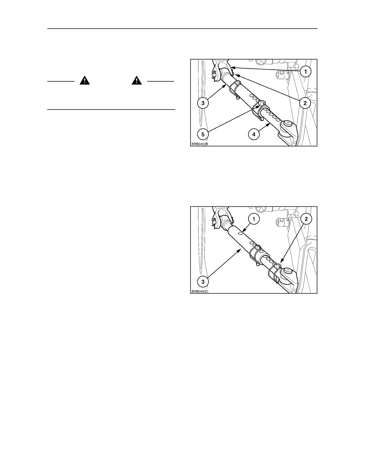
Each stabiliser consists of a round-section tube (3),
158
anchored by a pin (2) to a bracket (1) bolted to the
outer ends of the rear axle housing. A smaller
diameter inner section (4), attached to a bracket on
the lower links, is a loose, sliding fit within the outer
tube. The overall length of the stabiliser is
determined by the position of a pin (5) that passes
through holes in the tube and inner section.
The holes in the inner section and outer tube are
drilled at different centres so a wide range of
stabiliser settings may be achieved by passing the
pin through the most suitable pair of holes.
To adjust, attach the implement to the 3-point linkage
with the locating pin removed from both stabilisers.
When the implement is satisfactorily aligned, the
locating pins should be passed through any one of
the four holes in the outer tubes that align with one
of the holes in the sliding inner section. With the pins
inserted in this manner, both stabilisers will be locked
as rigid units and the implement will be prevented
from swaying both in work or when raised to the
159
transport position.
If the pin is removed from the front hole
(1)
Figure 159, the front end of the stabiliser (3) will be
allowed to telescope and a limited degree of sway will
be permitted. The unused pin should be re-inserted
in one of the spare holes (2) of the inner section for
safe storage.
IMPORTANT: Always ensure locking pin is replaced
in front stabiliser hole when no implement is
attached.
IMPORTANT: When setting the stabiliser length,
particularly if using the sway facility, ensure that
there is no possibility of the rear tyres fouling the
stabilisers or lower links.
3--92
SECTION 3 -- FIELD OPERATION
TELESCOPIC STABILISERS
(round section screw type -- where fitted)
WARNING
Never operate steerable equipment unless the
telescopic stabilisers are correctly adjusted to
prevent excessive lateral movement.
Telescopic stabilisers control the sway of the lower
links and attached equipment when in work or when
being transported.
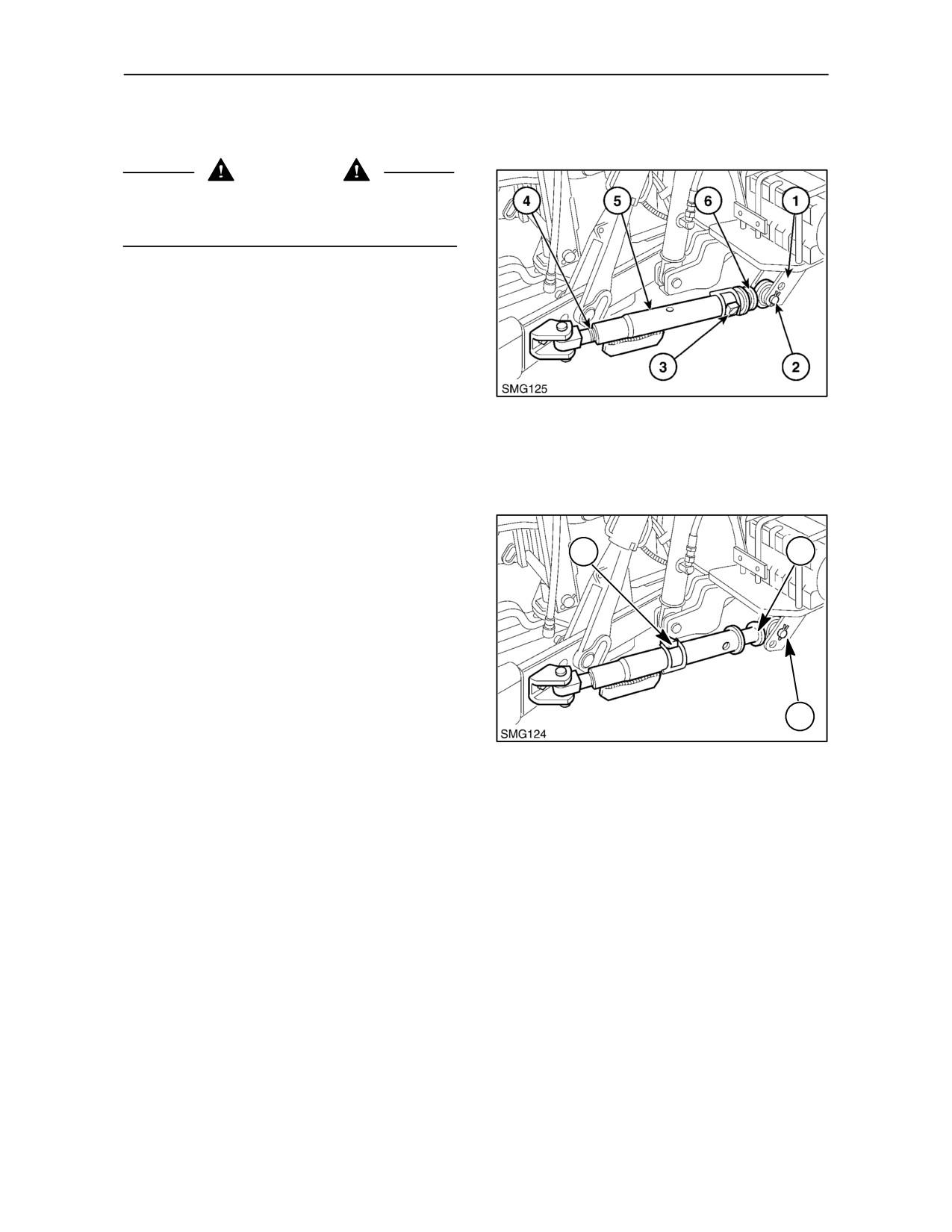
Each stabiliser consists of a tube (5), with a coupling
at each end. The front, sliding end (6) is attached to
a bracket (1) bolted to the outer end of the rear axle
housing. This coupling is a loose, sliding fit within the
160
tube. The overall length of the stabiliser is
determined by the position of a pin (3) that passes
through a hole in the tube. The rear end (4) is
attached to the 3--point linkage and is threaded to
provide fine adjustment.
To adjust, attach the implement to the 3-point linkage
with the locating pin removed from both stabilisers.
3
1
To remove the pin, pull back the securing clip. When
the implement is satisfactorily aligned, the locating
pin should then be passed through the holes and the
securing clip replaced. With the pin removed, the
tube may be rotated to provide fine adjustment and
the pin re-inserted.
With the pins inserted in the front holes, both
stabilisers will be locked as a rigid unit and the
implement will be prevented from swaying both in
2
work or or when raised to the transport position.
161
The front of each stabiliser is attached by a pin (2),
passing through holes in the mounting brackets. The
stabilisers are normally attached to the lower hole in
each bracket, to provide parallel lift.
IMPORTANT: The lower hole is the only hole to
which the stabilisers may be connected when locked
as a rigid unit, as described above, otherwise
damage to the lower links may occur when the
linkage is raised.
3--93
SECTION 3 -- FIELD OPERATION
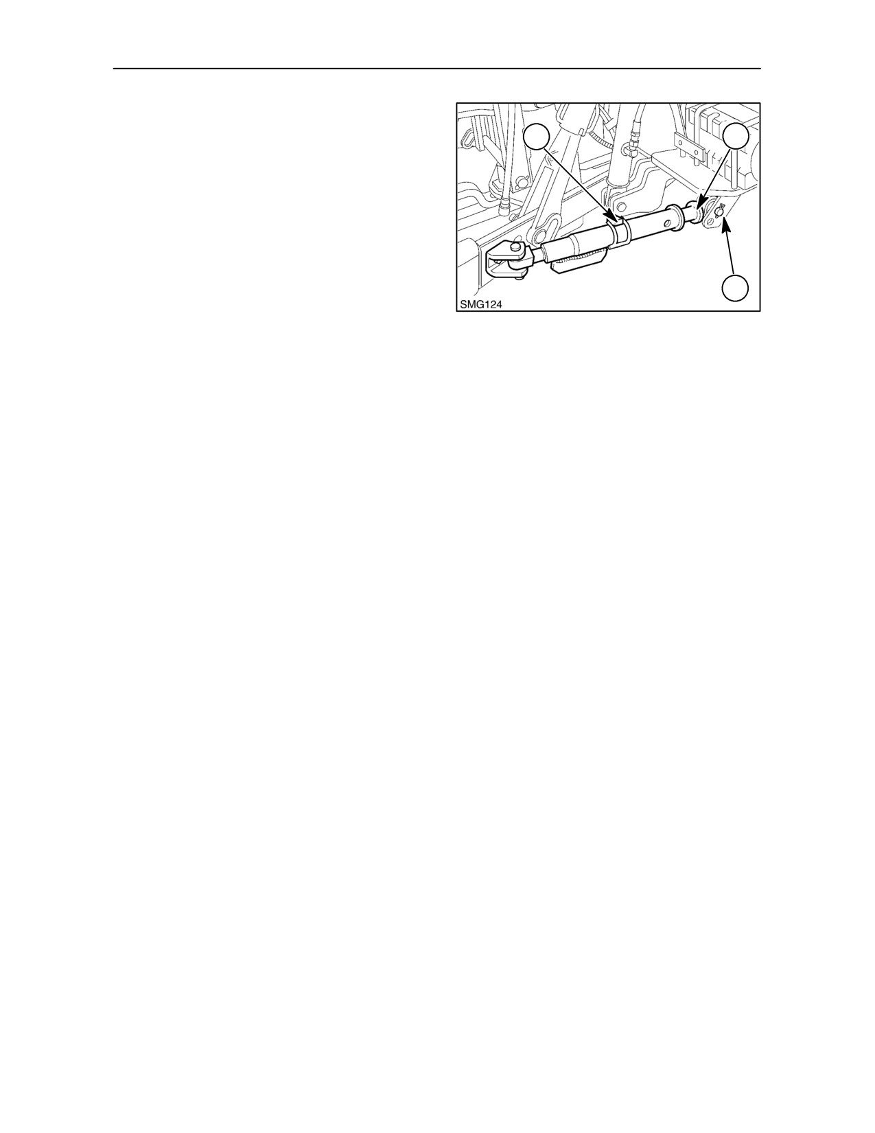
It may be desirable to allow equipment such as
ploughs etc., to sway from side to side.
3
1
If the pin is removed from the front hole, the front end
(1) of the stabiliser will be allowed to telescope and
a limited degree of sway will be permitted. The pin
should be re-inserted through the central hole, as
shown at (3) in Figure 161.
When the front of the stabiliser is attached to the
upper hole (2) in the front mounting bracket the
stabilisers will allow the implement to sway in work
2
with reduced sway when the implement is raised.
This feature provides greater implement control
162
when turning on the headlands of a field.
IMPORTANT: When setting the stabiliser length,
particularly if using the sway facility, ensure that
there is no possibility of the rear tyres fouling the
stabilisers or lower links.
3--94
SECTION 3 -- FIELD OPERATION
AUTOMATIC STABILISERS
Automatic stabilisers may be fitted in place of the
standard
telescopic
stabilisers,
described
previously.
WARNING
Never operate steerable equipment unless the
stabilisers are installed and correctly adjusted to
prevent excessive lateral movement.
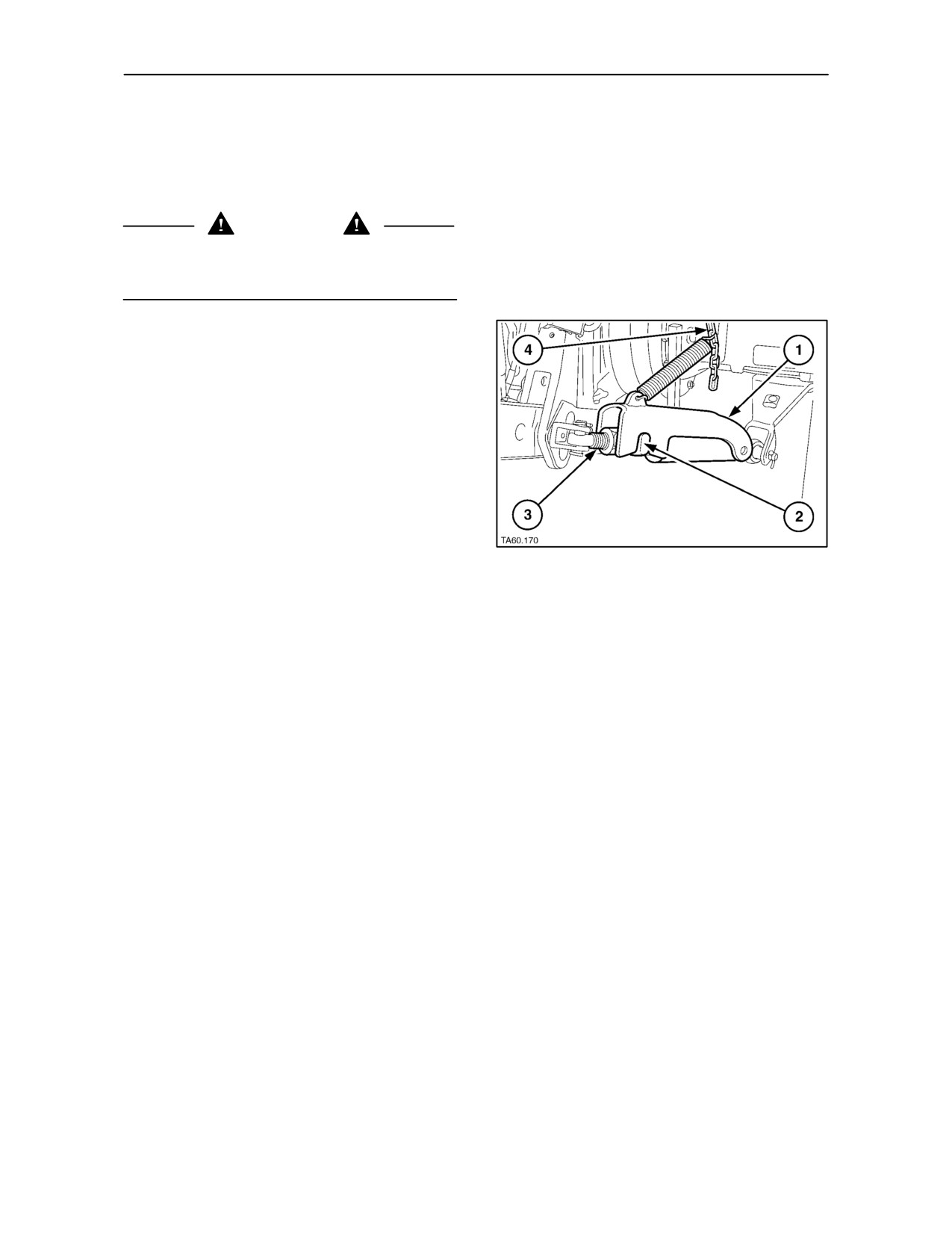
Each stabiliser consists of a telescopic tube
assembly internally threaded at the rear end. The
tube assembly is attached to a mounting bracket
bolted to the outer ends of the rear axle housing.
An externally threaded rod (3) is attached to the
lower links. The threaded rod engages with the
screwed thread in the tube assembly and the overall
length of the assembly is determined by screwing the
rod in or out, as required.
An adjustable chain (4) is attached, at one end, to
the rear fender and at the other end, via a spring,
to a hinged cover (1) on the telescopic part of the
stabiliser. A lug (2) on the telescopic part of the
163
stabiliser engages a notch in the cover.
When the chain is correctly adjusted it will be slack
when the lower links are raised from the operating
position, so allowing the cover to drop down over the
lug on the stabiliser. When the cover is down, as
shown, the stabiliser is locked at the preset length.
The lower links are, therefore, retained at a set
distance apart, preventing them
(and attached
equipment) from swaying.
However, when the 3--point hitch is lowered into the
work position, the chain becomes taut and lifts the
cover from the stabiliser allowing it to telescope
freely. The stabilisers (and implement) will then sway
when engaged in the ground. This feature is useful
as it provides greater implement control when turning
on the headlands of a field.
3--95
SECTION 3 -- FIELD OPERATION
Adjusting the Stabilisers
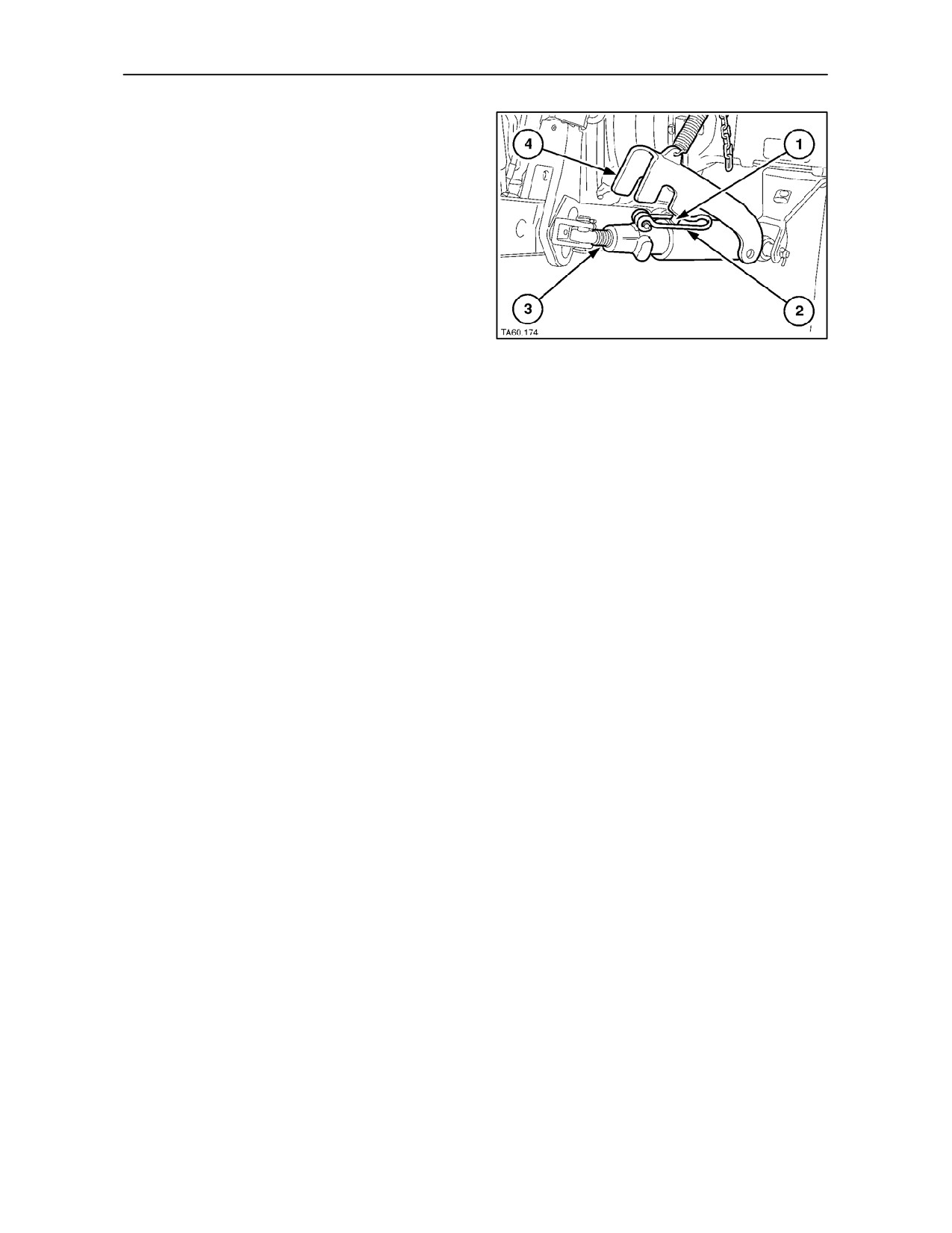
In practice, the implement should be attached to the
three--point linkage with the cover
(4) on both
stabilisers raised, so as to allow the stabilisers to
telescope freely.
Lift the locking/adjusting lever (2) up over the peg (1)
so that the lever is at right-angles to the stabiliser. Turn
the telescopic section, by means of the lever, so that
the threaded section (3) screws into or out of the
stabiliser. When the length is satisfactory, i.e., the notch
in the cover aligns with the lug on the stabiliser, lower
the lever back down over the peg and close the cover.
164
The chain should then be adjusted, by placing the
appropriate link over the attaching hook, so that the
cover on the stabiliser is lifted when the implement
is lowered into work.
IMPORTANT: When setting the stabiliser length to
provide sway, ensure that there is no possibility of the
rear tyres fouling the stabilisers or lower links.
3--96
SECTION 3 -- FIELD OPERATION
DRAWBARS AND TOWING ATTACHMENTS
NOTE: Before attaching trailed equipment to the
Always use a safety chain installed between the
tractor, read the following text carefully.
tractor and implement hitch when transporting
equipment on the highway. See page 3--101.
ATTACHING/DETACHING TRAILED
EQUIPMENT
Observe the following precautions for towing
equipment not equipped with brakes:
IMPORTANT: Regulations in some areas require
brakes on towed equipment when operating on the
• Do not tow equipment weighing more than twice
public highway. Before travelling on public roads,
the tractor weight.
make sure you comply with the legal requirements
for your country.
• Do not exceed 10 MPH (16 km/h) if towed
equipment weighs more than the tractor.
To attach the tractor to trailed equipment and
implements:
• Do not exceed 20 MPH (32 km/h) while towing
equipment that weighs less than the tractor.
1. Ensure that the implement is at draw bar height.
DRAWBAR SAFETY
2. Slowly inch rearwards to allow the drawbar and
implement hitch to align.
WARNING
Do not pull from the lower links with the links above
3. Apply the parking brake and stop the engine.
the horizontal position. Always use the drawbar,
pick-up hitch or lower links in the lowered position for
4. Insert the hitch pin and ensure that the retainer
pull-type work, otherwise the tractor may overturn
is in the latched position.
rearwards.
IMPORTANT: When attaching mounted or
semi-mounted equipment to the 3-point linkage or
when attaching trailed equipment to the drawbar or
NOTE: When supporting equipment on the drawbar
hitch, ensure that there is adequate clearance
ensure that the total weight on the rear axle does not
between the implement and the tractor.
exceed the maximum static downward load or the
Semi-mounted or trailed equipment may interfere
rear tyre load capacity, whichever is the lower (see
with the tractor rear tyres. If necessary, adjust
Tyre Pressures and Permissible Loads at the end of
steering stops (four wheel drive only) or linkage
Section 3).
stabilisers.
IMPORTANT: When transporting equipment on the
NOTE: For implements that require hitch extensions
highway it is recommended that a safety chain
or interfere with the tractor clevis, remove and store
having a tensile strength equal to the gross weight of
the clevis and hitch pin.
the implement be installed between the tractor and
implement hitch. See Safety Chain on page 3--101.
3--97
SECTION 3 -- FIELD OPERATION
SWINGING DRAWBARS
Two types of swinging drawbar are available. The
sliding type is illustrated in Figure 165. This drawbar
may be installed as part of a tow hitch or as an
independent unit.
The roller type, shown in Figure 168, is
recommended when heavy draft, trailed equipment
is used for extended periods. This drawbar is
mounted on rollers and offers additional turning ease
when compared with the sliding type.
Sliding Type Swinging Drawbar
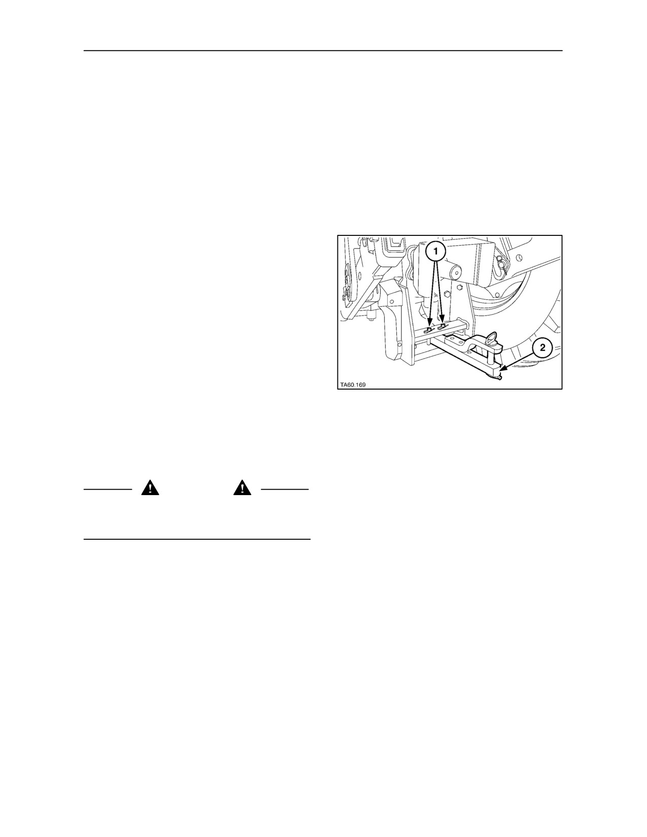
The drawbar (2) pivots about a single pin at the front
end so as to allow the rear of the drawbar to swing
the full width of the hanger. By inserting the swing
limiter pins (1) in the appropriate holes, restricted
movement of the drawbar is permitted. Alternatively,
the drawbar can be pinned in any one of three
positions by insertion of the pins in the appropriate
holes. In Figure 165, the drawbar is shown pinned in
the central position to prevent swinging.
Pin the drawbar to prevent swinging when pulling
equipment which requires accurate positioning and
165
when transporting equipment.
Allow the drawbar to swing when pulling ground
engaging equipment which does not require
accurate positioning. This will make steering and
turning easier.
WARNING
Always secure the drawbar to prevent swinging
when transporting equipment or when operating any
but ground engaging equipment.
The drawbar is adjustable for height and projection
relative to the end of the P.T.O. shaft. To vary the
height of the drawbar/implement hitch point, remove
the drawbar and invert it.
3--98
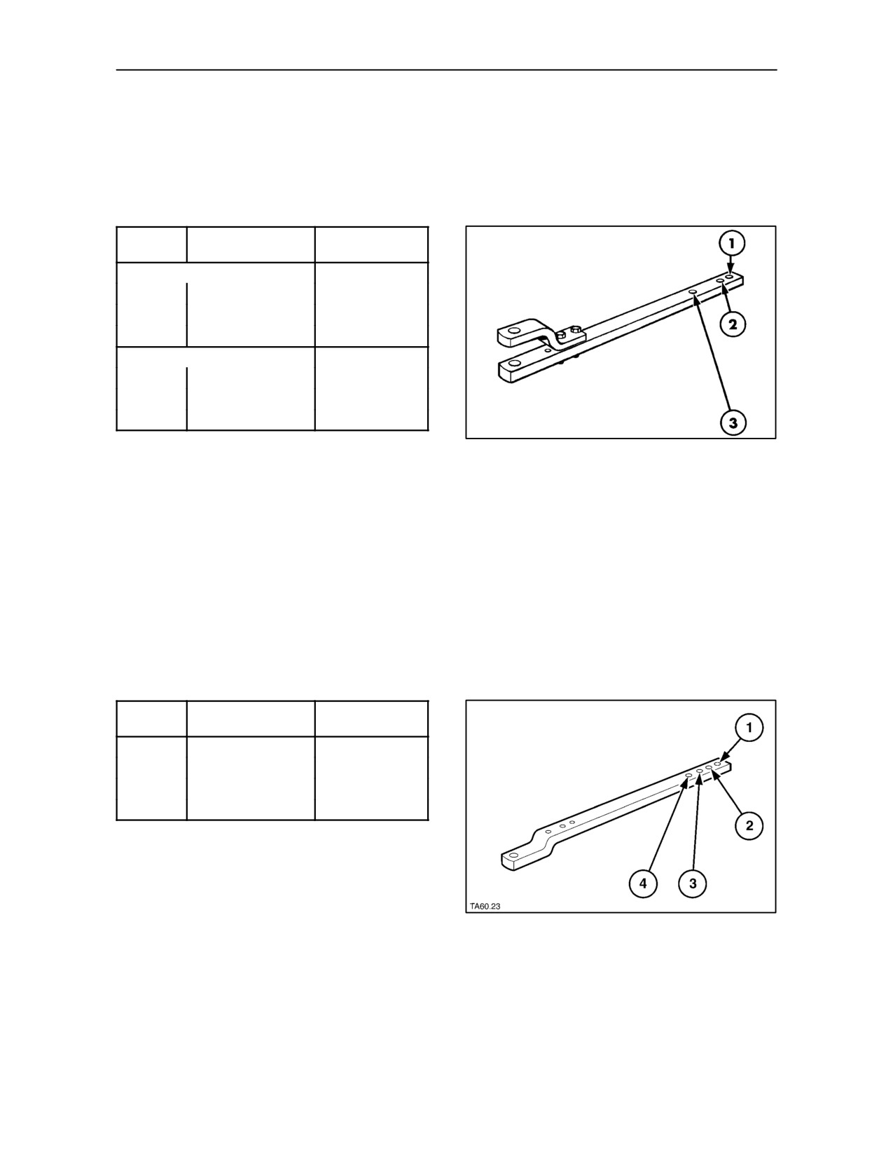
SECTION 3 -- FIELD OPERATION
All Countries Except North America
The front securing pin may be inserted in one of three
holes in the drawbar to vary the P.T.O. shaft to hitch
point distance. See Figure 166 and the following
table:
Hole (see
P.T.O Shaft to
Maximum Static
Fig. 166)
Drawbar Hitch Point
Downward Load
Drawbar clevis uppermost
1
406 mm (16 in.)
1140 kg (2513 lb.)
2
356 mm (14 in.)
1330 kg (2932 lb.)
3
243 mm (9.6 in.)
2040 kg (4497 lb.)
Drawbar clevis underneath
1
406 mm (16 in.)
1045 kg (2300 lb.)
2
356 mm (14 in.)
1225 kg (2700 lb.)
3
243 mm (9.6 in.)
1305 kg (2875 lb.)
Use of hole 1 is required for 1000 rev/min P.T.O.
166
operations and hole
2
for
540
rev/min P.T.O.
operations.
When towing equipment exerting high static
downward forces, such as two-wheeled trailers, etc.,
use the close-coupled position -- hole 3.
North America only
The front securing pin may be inserted in one of four
holes in the drawbar to vary the P.T.O. shaft to hitch
point distance. See Figure 167 and the following
table:
Hole (see
P.T.O Shaft to
Maximum Static
Fig. 167)
Drawbar Hitch Point
Downward Load
1
406 mm (16 in.)
1140 kg (2513 lb.)
2
356 mm (14 in.)
1330 kg (2932 lb.)
3
304 mm (12 in.)
1535 kg (3384 lb.)
4
228 mm (9 in.)
2040 kg (4497 lb.)
Use of hole 1 is required for 1000 rev/min P.T.O.
operations and hole
2
for
540
rev/min P.T.O.
operations.
When towing equipment exerting high static
downward forces, such as two--wheeled trailers,
167
etc., use the close-coupled positions -- holes 3 or 4.
3--99
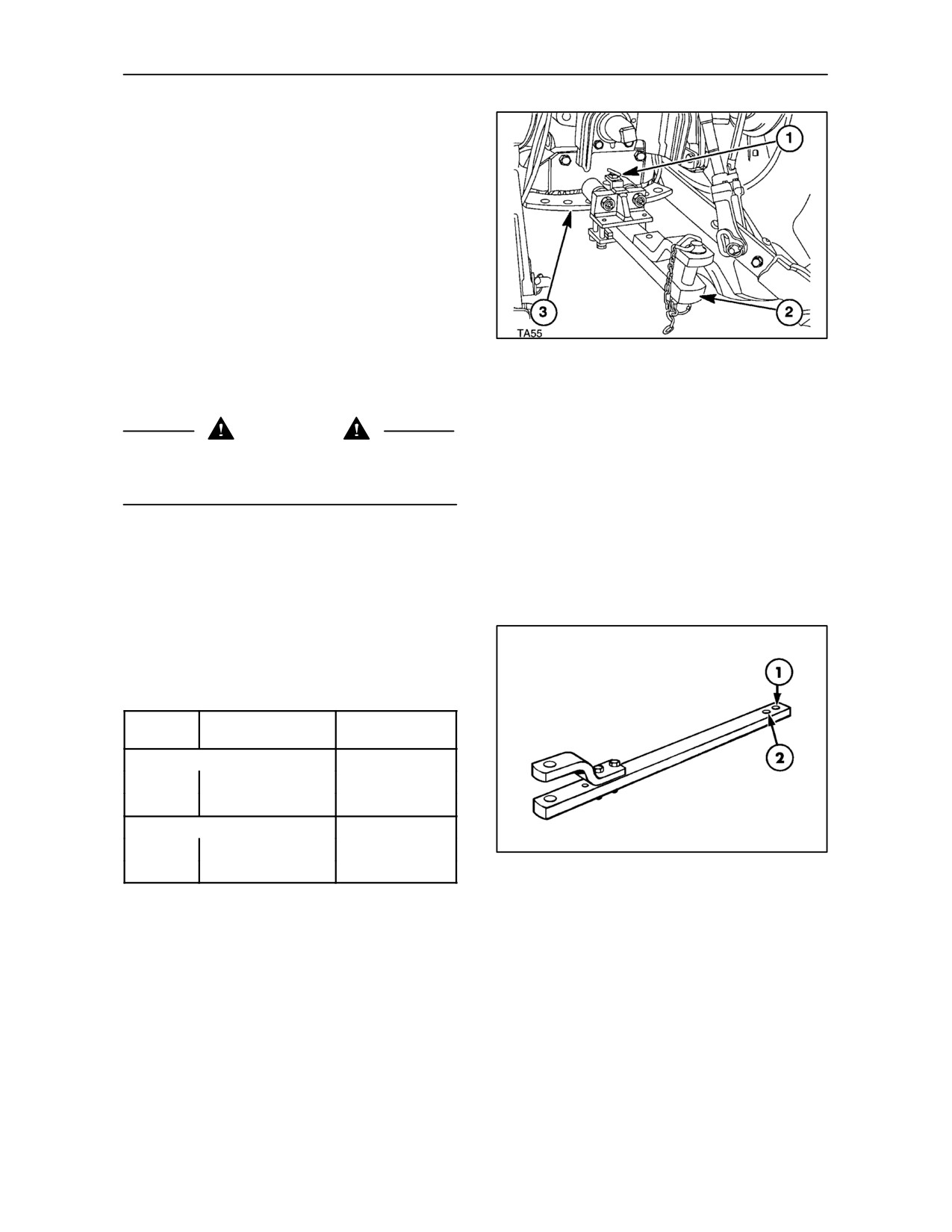
SECTION 3 -- FIELD OPERATION
Roller Type Swinging Drawbar
The drawbar (2) Figure 168, pivots about a single pin
at the front end so as to allow the rear of the drawbar
to swing the full width of the hanger. By inserting the
swing limiter pin (1) in the appropriate hole and
through the drawbar, the drawbar can be pinned in
any one of seven positions. Alternatively, the
drawbar may be allowed to swing the full width of the
hanger (3).
Pin the drawbar to prevent swinging when pulling
equipment which requires accurate positioning and
when transporting equipment. Allow the drawbar to
168
swing when pulling ground engaging equipment
which does not require accurate positioning. This will
make steering and turning easier.
WARNING
Always secure the drawbar to prevent swinging
when transporting equipment or when operating any
but ground engaging equipment.
The drawbar is adjustable for height and projection
relative to the end of the P.T.O. shaft. To vary the
height of the drawbar/implement hitch point, remove
the drawbar and invert it.
The front securing pin may be inserted in one of two
holes in the drawbar to vary the P.T.O. shaft to hitch
point distance. See Figure 169 and the following
table:
Hole (see
P.T.O Shaft to
Maximum Static
Fig. 169)
Drawbar Hitch Point
Downward Load
Drawbar clevis uppermost
1
406 mm (16 in.)
1360 kg (2995 lb.)
2
356 mm (14 in.)
1630 kg (3590 lb.)
Drawbar clevis underneath
1
406 mm (16 in.)
1045 kg (2303 lb.)
169
2
356 mm (14 in.)
1225 kg (2700 lb.)
Use of hole 1 is required for 1000 rev/min P.T.O.
operations and hole
2
for
540
rev/min P.T.O.
operations.
When towing equipment exerting high static
downward forces, such as two-wheeled trailers, etc.,
use hole 2.
3--100
SECTION 3 -- FIELD OPERATION
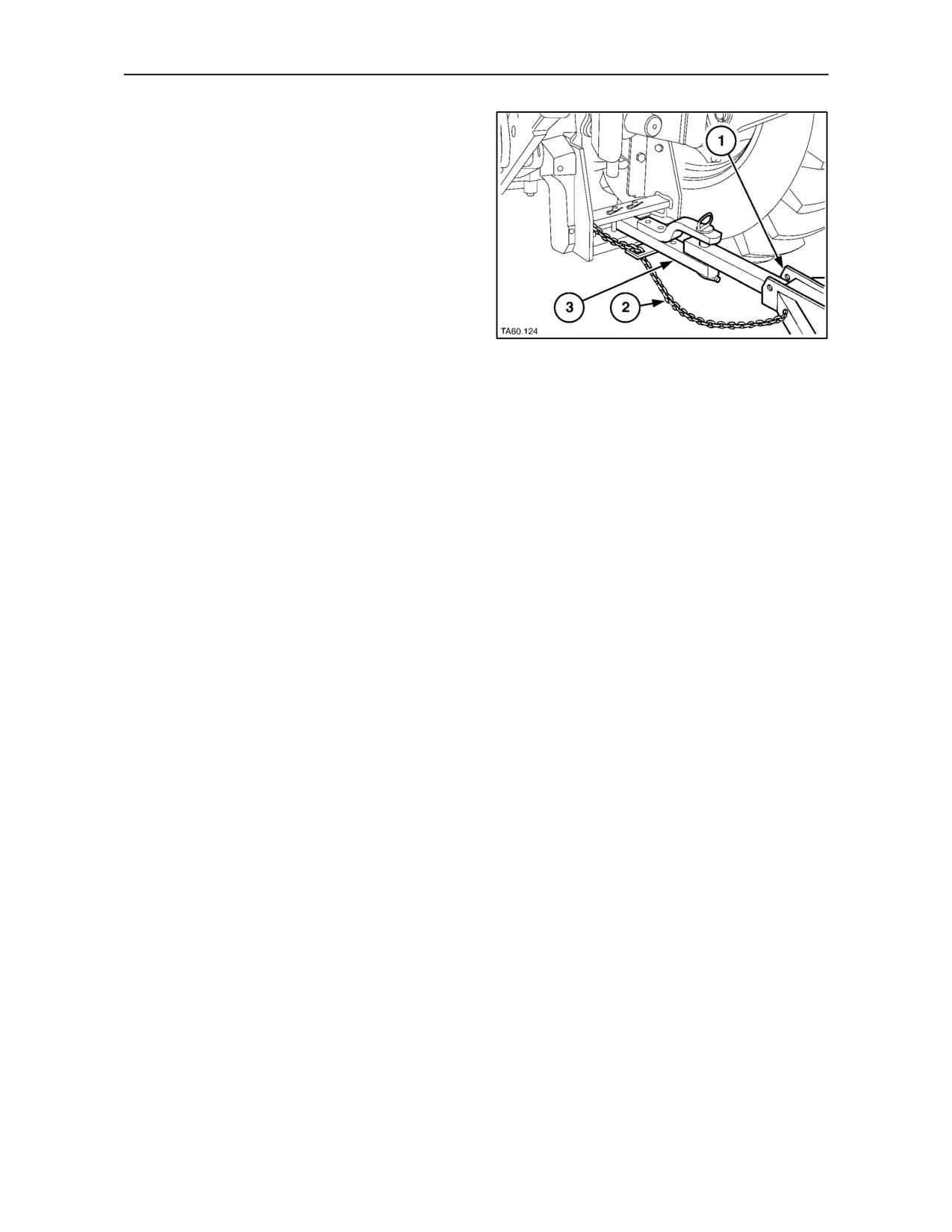
SAFETY CHAIN
When towing implements on public roads, use a
safety chain (2) with a tensile strength equal to or
greater than the gross weight of the implement to be
towed. This will control the implement (1) in case the
drawbar (3) and implement become disconnected.
After attaching the safety chain, make a trial run by
driving the tractor to the right and to the left for a short
distance to check the safety chain adjustment. If
necessary, re-adjust to eliminate a tight or loose
chain.
170
Check the implement operator’s manual for
implement weight and attaching hardware
specifications.
Safety chains, attaching hardware and chain guide
are available from your authorised dealer.
3--101
SECTION 3 -- FIELD OPERATION
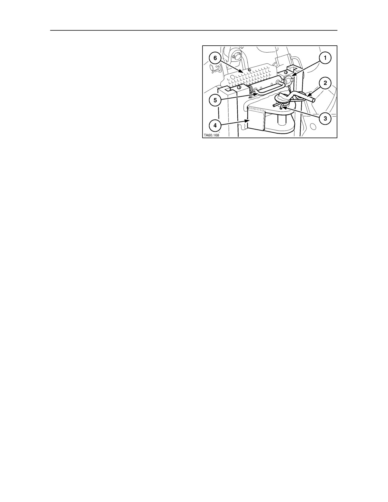
REAR TOW HITCH
Description
Various rear tow hitch options are available. All
versions consist of a fabricated steel frame bolted to
the rear axle centre housing. A tow pin is provided,
adjustable for height.
The slider type frame is shown in Figures 172
and 173. Rotating pins in the tow pin assembly
engage in notches in the frame to secure the tow pin
at the required height. With this type of frame, a
second, fixed tow pin (piton) is available as an option.
171
The piton is installed at the bottom of the assembly.
Four types of tow pin assembly are available :--
• Non-swivelling tow pin.
• Heavy duty non-swivelling tow pin.
See Figure 173.
• Swivelling tow pin -- manual operation.
See Figure 177.
• Swivelling tow pin -- auto operation.
See Figure 179.
A swinging drawbar may also be provided as part of
the assembly. See ‘Sliding Type Swinging Drawbar’
on page 3--98 for details of drawbar operation.
NOTE: The tow hitch is designed primarily for use
with four wheel trailers which do not place a heavy
downward load on the tow pin. Observe the
maximum static downward loads quoted in the text.
3--102
SECTION 3 -- FIELD OPERATION
Slider Frame with non-swivelling Tow Pins
(dealer installed accessory)
The tow hitches shown are equipped with a height
adjustable, non-swivelling, tow pin assembly. The
standard tow pin is shown in Figure 172. Figure 173
shows the heavy duty tow pin.
172
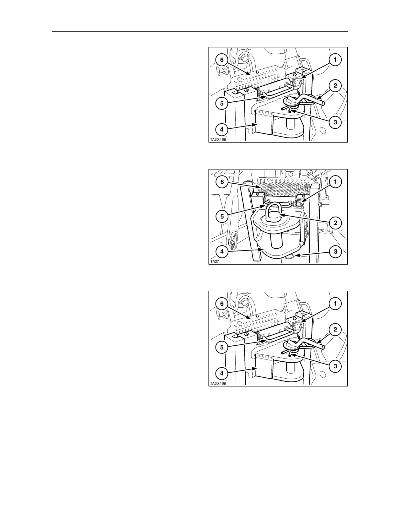
Remove the securing clip (1) and lift the handle (5) to
the vertical position. Lifting the handle will rotate the
pins and disengage them from the notches in the
frame. Using both hands on the handle (5) lift or lower
the tow pin assembly (4), as required. When at the
required height, support the tow pin with one hand and
lower the handle to the horizontal position, as shown
in Figures 172
and 173. The pins will rotate and
re-engage the notches in the frame. Lower the P.T.O.
guard (6).
173
To attach a trailer drawbar to the tow pin, remove the
‘R’ clip (3) from the tow pin and lift out using the
handle (2). Re-insert the tow pin so that it passes
through the eye of the trailer drawbar. Replace the ‘R’
clip.
NOTE: The static downward load on the tow pin must
not exceed the rear tyre load capacity or the following
values, whichever is lower. (See Tyre Pressures and
Permissible Loads at the end of Section 3).
Standard tow pin (Fig. 172)
1500 kg (3300 lb.)
Category D2 tow pin (Fig. 173)
2000 kg (4400 lb.)
174
3--103
SECTION 3 -- FIELD OPERATION
NOTE: A Category D3 tow pin (with housing) is
available as a dealer installed accessory. The static
downward load on the Category D3 tow pin should
not exceed 2500 kg (5500 lb.) or the rear tyre load
capacity, whichever is lower. (See Tyre Pressures
and Permissible Loads at the end of Section 3).
175
Slider Frame with Swivelling Tow Pins
The tow hitches shown are equipped with a height
adjustable, swivelling tow pin assembly with manual
or auto operation.
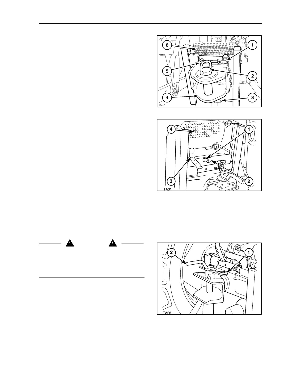
With reference to Figure 176, adjust the height of the
tow pin assembly, as follows:
Grasp the handle (2) with the right hand. Press and
hold in the button (1) to release the locking mechanism.
Pull the handle (3) down to the horizontal position with
the left hand and release the push button to lock the
handle (3) in the horizontal position. Lowering the
176
handle will rotate the pins and disengage them from the
frame. Using both handles, lift or lower the complete
tow pin assembly. When at the required height, hold in
the push button and lift the left-hand handle up to the
vertical position, as shown in Figure 176. The pins will
rotate and re-engage the notches in the frame. Lower
the P.T.O. guard (4).
WARNING
Before attaching a trailer, ensure that the pins are
fully engaged in the notches, i.e. the handle (3)
Figure 176, is in the vertical position. The tow pin
assembly must not rest on the P.T.O. guard or on the
bolt heads at the end of the slider guides.
To attach a trailer drawbar to the upper tow pin, see
the following text:
177
3--104
SECTION 3 -- FIELD OPERATION
Swivelling Tow Pin -- Manual Engagement
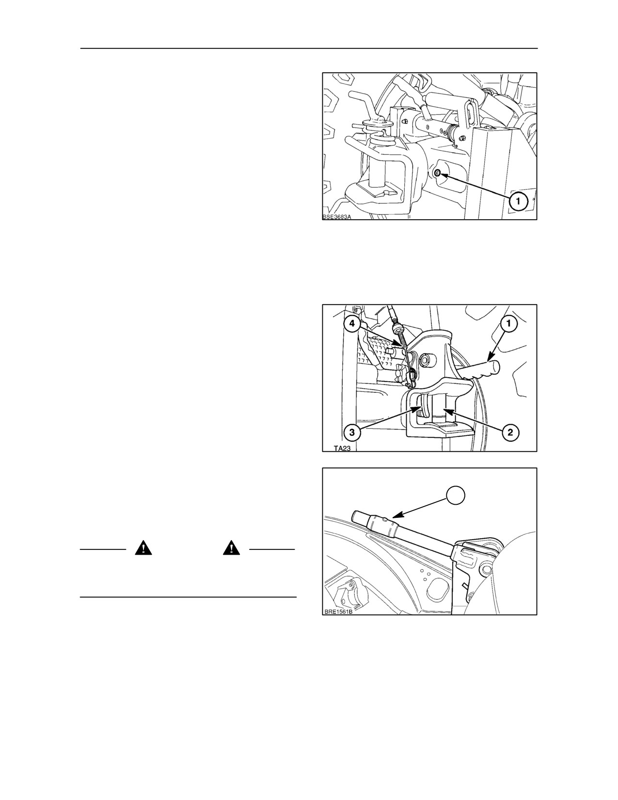
To attach a trailer drawbar to the tow pin, remove the
‘R’ clip (1) Figure 177, from the tow pin and lift out
using the handle (2). Re-insert the tow pin so that it
passes through the eye of the trailer drawbar.
Replace the ‘R’ clip.
The tow pin may be allowed to swivel after loosening
the socket-headed screw (1) Figure 178 on the side
of the tow pin assembly. This feature will permit a
trailer with a non-swivelling drawbar to articulate
relative to the towing tractor.
178
NOTE: The static downward load on the tow pin must
not exceed 2000 kg (4400 lb.) or the rear tyre load
capacity, whichever is lower. (See Tyre Pressures
and Permissible Loads at the end of Section 3).
Swivelling Tow Pin -- Auto Engagement
The tow pin (2) Figure 179, is spring-loaded in the
engaged (down) position, as shown. To attach a trailer
to the tow pin, lift the release lever (1) to the vertical
position to retract the tow pin up into it’s housing.
The release lever is connected by the cable (4) to a
handle in the cab. This will permit trailer attachment
without leaving the cab. To actuate the cable release
and retract the tow pin, slide the collar (1) upwards to
release the lock and then pull up the handle.
179
The pin will stay in the raised position until the trailer
drawbar is located beneath it. The eye of the drawbar
will contact the trip lever (3) Figure 179 and cause
1
the pin to drop down into the engaged position.
Alternatively, the tow pin will drop down into the
engaged position if the lever (1) is pulled down.
WARNING
Do not attempt to trip the lever by hand as the fingers
may be trapped by the action of the spring-loaded
tow pin.
180
3--105
SECTION 3 -- FIELD OPERATION
The tow pin may be allowed to swivel after loosening
the socket-headed screw (1) Figure 178 on the
underside of the tow pin assembly. This feature will
permit a trailer with a non-swivelling drawbar to
articulate relative to the towing tractor.
IMPORTANT: Do not allow the tractor tow pin to
swivel if the trailed equipment is equipped with a
swivelling tow pin connector.
NOTE: The static downward load on the tow pin must
not exceed 2000 kg (4400 lb.) or the rear tyre load
capacity, whichever is lower. (See Tyre Pressures
and Permissible Loads at the end of Section 3).
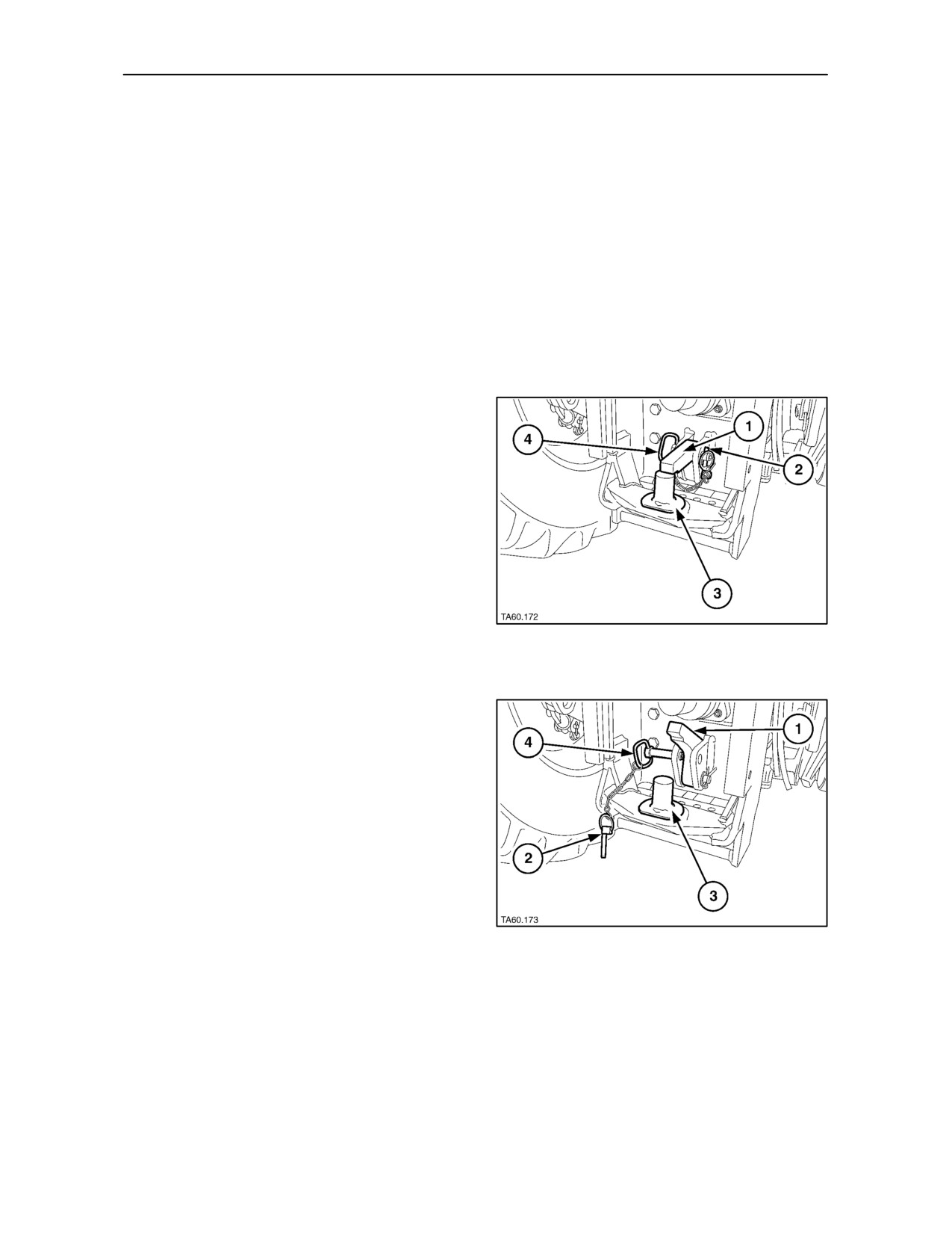
Fixed Tow Pin (Piton)
An optional fixed tow pin (piton) may be provided at
the bottom of the assembly.
To attach a trailer to the piton, remove the linch pin
(2) and withdraw the retaining pin (4). Lift the security
latch (1) and lower the eye of the trailer drawbar over
the piton (3). Drop the security latch down, re-insert
the retaining pin and secure with the linch pin. The
security latch will ensure that the trailer cannot
become accidentally detached from the piton
NOTE: The static downward load on the piton must
181
not exceed 3000 kg (6600 lb.) or the rear tyre load
capacity, whichever is lower. (See Tyre Pressures
and Permissible Loads at the end of Section 3).
182
3--106
SECTION 3 -- FIELD OPERATION
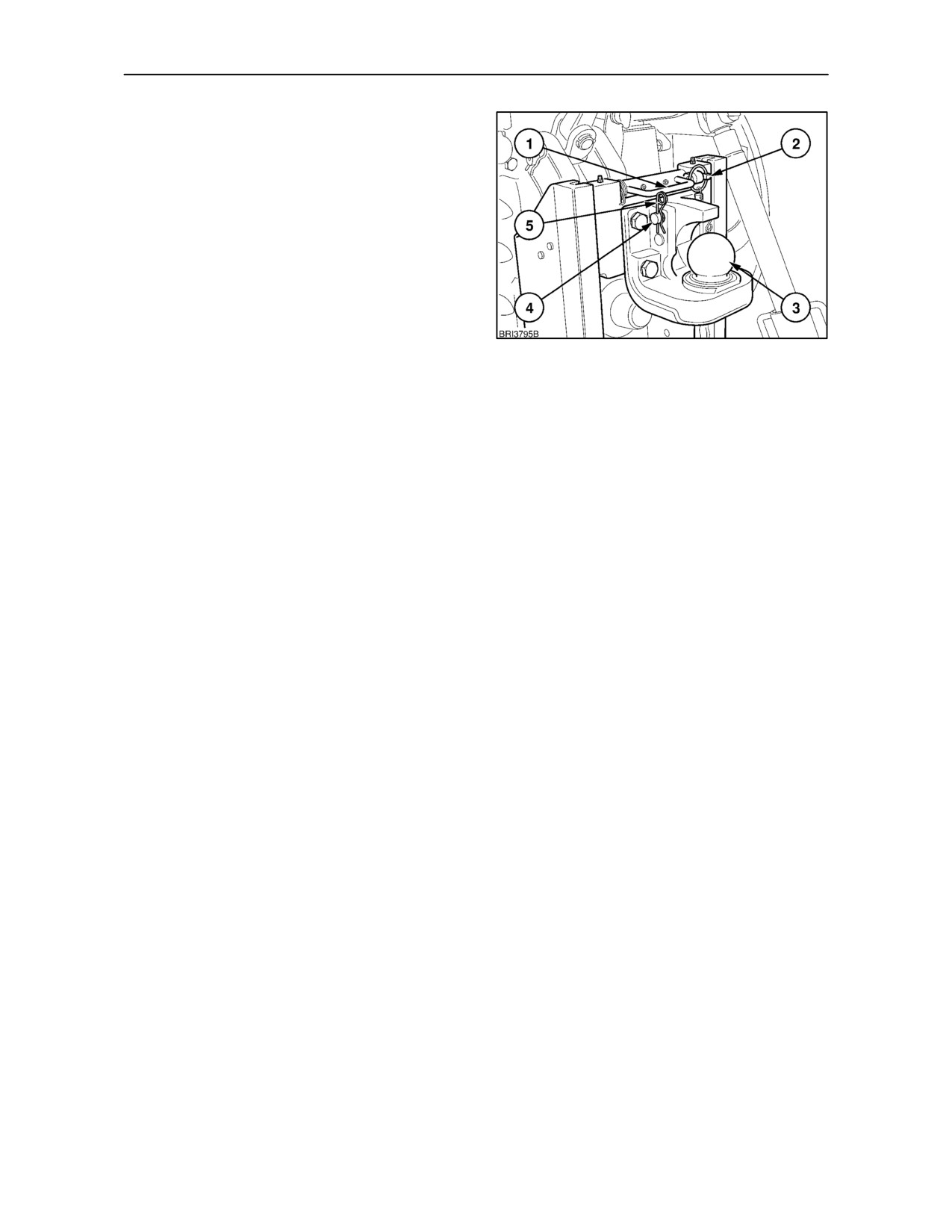
Slider Frame with K 80 Ball
The tow hitch shown is equipped with a height
adjustable, 80 mm ball assembly.
Remove the securing clip (2) and lift the handle (1) to
the vertical position. Lifting the handle will rotate the
pins and disengage them from the notches in the
frame. Using both hands on the handle, lift or lower the
tow ball assembly (3) as required. When at the required
height, support the tow ball with one hand and lower the
handle to the horizontal position. The pins will rotate
and re-engage the notches in the frame. Lower the
P.T.O. guard.
183
NOTE: When setting the height of the tow ball, it
should be adjusted to the lowest position relative to
the correct operating height of the implement
drawbar.
To attach a trailer, remove the ’R’ clip (5) and pull out
the locking pin (4). This will allow the security latch
to pivot forwards toward the tractor. When the
implement drawbar has been securely attached,
replace the locking pin so it passes through the
security latch and re--insert the ’R’ clip.
NOTE: The static downward load on the tow ball
must not exceed 3000 kg (6600 lb.) or the rear tyre
load capacity, whichever is lower.
(See Tyre
Pressures and Permissible Loads at the end of
Section 3).
3--107