New Holland T6010, T6020, T6030, T6050, T6070 Delta and Plus Tractors. Operator's Manual - page 4
SECTION 2 -- CONTROLS, INSTRUMENTS AND OPERATION
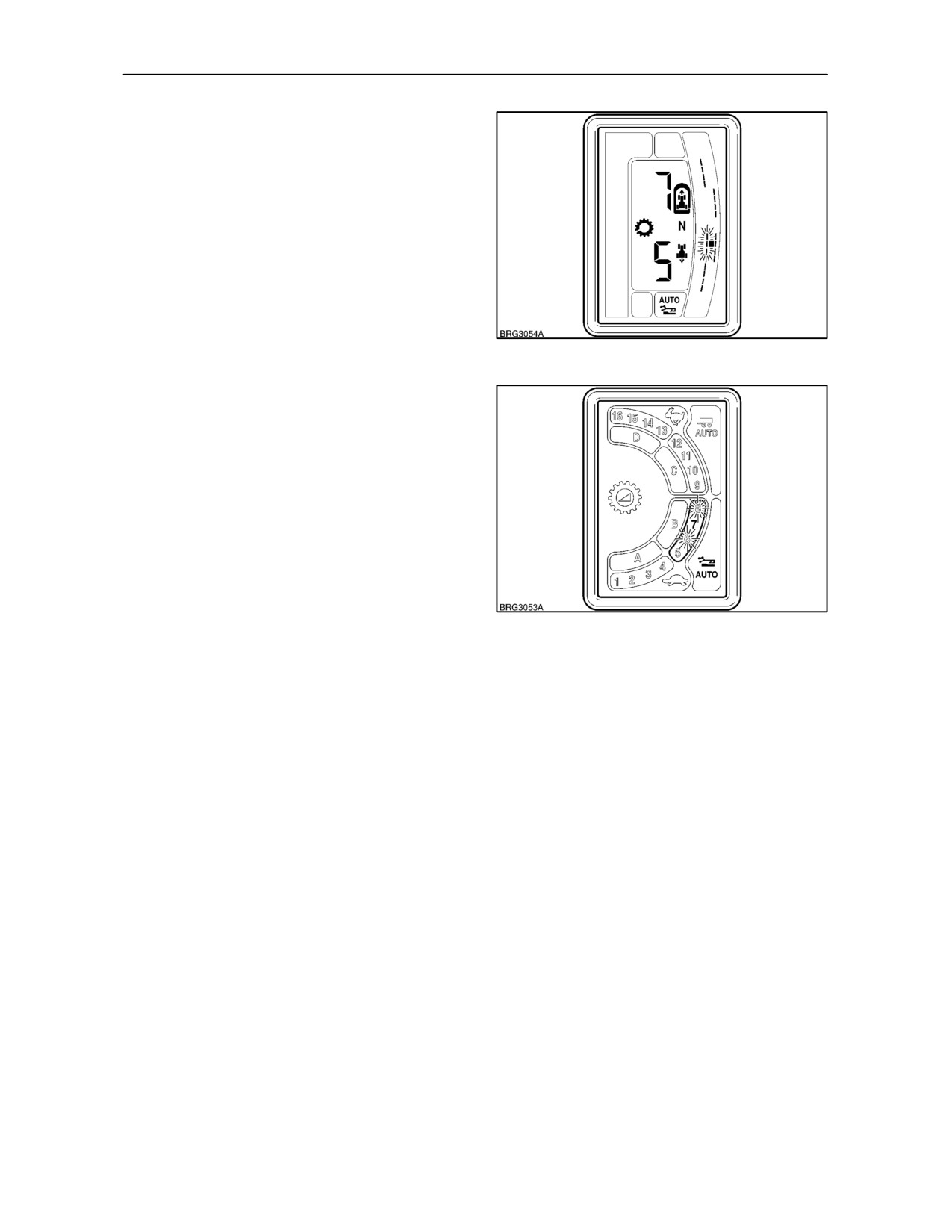
The Auto Shift gear span is shown in the
transmission display. Figures 142 and 143 show a 3
gear span of 6, 7 and 8. The currently selected gear
is 7th.
Digital Display: The span of gears will be
represented by flashing bars and the selected gear
by the solid block, see Figure 142.
LED Display: The span of gears will be identified by
flashing digits and the engaged gear by the
permanently lit digit, see Figure 143.
142
With Auto Shift in standby mode, the operator can
manually shift to any gear, even if it is outside the
current range of Auto Shift gears. Providing the
operator selects a gear within the current Auto Shift
range prior to exiting standby mode (i.e. lowering the
3--point hitch), then the Auto Shift function will be
resumed.
However, if the gear selected is outside the current
range when exiting standby, the Auto Shift function
will be cancelled.
If 8th gear is selected and the Auto Shift span is 5,
6 and 7, then the transmission will immediately
143
downshift to 7th gear on exiting standby mode.
If the Auto Shift span is 6, 7 and 8 and 5th gear is
selected on exiting the standby mode, then the
transmission will remain in 5th until conditions permit
a normal auto upshift to 6th gear. At this point the
original Auto Shift gear span of 6, 7, and 8 will be
re--instated.
2--94
SECTION 2 -- CONTROLS, INSTRUMENTS AND OPERATION
Auto Shifting in Road Gears
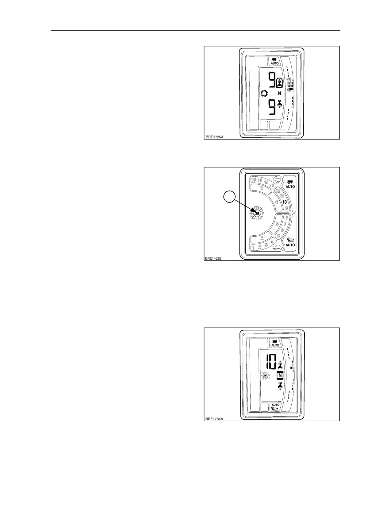
In Active Road, Auto Shift will make upshifts or
downshifts through gears 9--12 or 13--16. With the
main shift lever moved fully forward, momentarily
depress the Auto Shift button (1), the Active Road
symbol (trailer) will illuminate in the gear display to
confirm engagement.
The transmission will now make automatic shifts
through gears 9 to 12 or 13 to 16 dependant on the
range selected.
By depressing the Auto Shift button twice, Active
Road can be programmed to automatically upshift or
144
downshift through gears 9 to 16 including the range
change from 12th to 13th gear.
Changing the Shift Point
To suit different applications, the point at which the
transmission makes an automatic gear shift may be
adjusted from the default setting of 20%. Auto Shift
1
gear changes are related to an increase or decrease
in engine speed which can be set at 5, 10, 15, 20 or
25 percent.
NOTE: For transport operations the shift point will
automatically default to 20% if a lower figure has
been set. If the shift point is set at 25%, it will remain
at that setting.
With the shift point set at 10%, a transmission upshift
145
will occur every time the engine speed increases by
10%. Consequently, as the engine speed decreases
by the same amount, the transmission will make a
downshift.
It is recommended that during field operations the
shift point is set at a low percentage, and for road
transport applications, set at a higher figure.
To change the shift point, depress and hold the Auto
Shift button for at least one second. The current shift
point figure appears in the Display of Gears and the
’ramp’ symbol (1) begins to flash. Depress the Auto
Shift button repeatedly to scroll through the shift
points.
With the new shift point selected, release the Auto
Shift button and pause for five seconds. The new
setting will be memorised and the display will return
to normal.
IMPORTANT: At key--off (engine stop), electronic
programme settings made during tractor operation
are transferred from the operating memory to the
146
main memory. To provide sufficient time for the data
to transfer, allow a minimum of five seconds delay
before turning the key on again.
2--95
SECTION 2 -- CONTROLS, INSTRUMENTS AND OPERATION
Error Codes
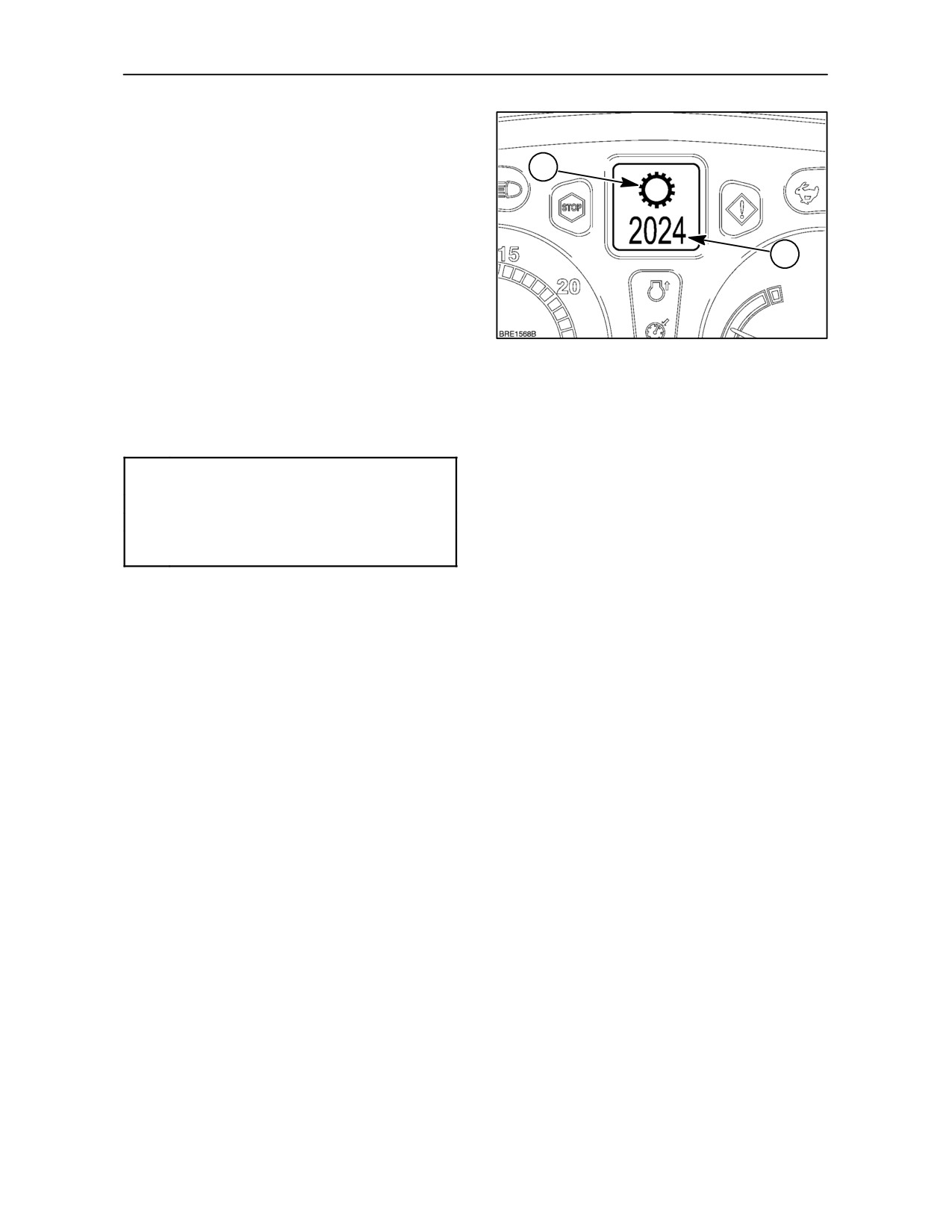
In the unlikely event of a fault occurring in the
transmission controls or electronic circuitry, the
1
malfunction symbol (1) and a four-digit error code
(2), will appear in the Dot Matrix Display.
The code indicates the faulty circuit or sensor and the
type of fault, e.g., open circuit, short circuit, etc. In
2
this event, the tractor will require the attention of your
authorised dealer.
Should a fault occur causing the tractor to become
disabled, contact your authorised dealer and report
the error code displayed.
147
There are a number of ’action reqired’ error codes
which can also appear in the Dot Matrix Display,
these are listed below.
Error
Code Fault
P
Park brake on.
N
Place the shuttle lever in neutral.
CP
Depress clutch pedal to enable
transmission (restore drive).
Transmission Calibration
Should transmission shifts become slow or jerky, the
clutches in the transmission may require
re--calibrating. Consult your authorised dealer.
2--96
SECTION 2 -- CONTROLS, INSTRUMENTS AND OPERATION
Creeper Gears (where fitted)
For operations requiring extra low ground speeds,
reduction gear sets (creeper gears) are available.
The reduction gear set is installed within the rear axle
assembly.
As the name implies, the reduction gear set has the
effect of reducing all the ratios within the main
transmission to provide an additional sixteen gears
in forward and reverse.
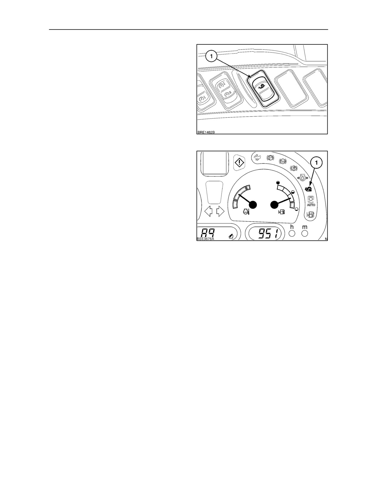
The creeper gears are selected by means of a rocker
switch (1) located on the right-hand control console.
148
With the engine running, clutch depressed and the
shuttle lever in neutral, apply and hold down the
tractor footbrakes. Momentarily depress the upper
part of the selector switch (1), Figure 148, to engage
the creeper gears.
The creep speed symbol (1), will appear flashing in
the transmission display. When the creep gears are
fully engaged the symbol will cease to flash and
become steady.
To disengage creeper gears, repeat the above
procedure and depress the selector switch again.
The creep speed symbol will cease to illuminate.
149
IMPORTANT: The creeper gears offer very low
ground speeds. Do not use the low gearing
advantage to apply excessive draft loads to the
tractor.
2--97

SECTION 2 -- CONTROLS, INSTRUMENTS AND OPERATION
GROUND SPEEDS in Km/h and (MPH) at Rated Engine Speed (2200 rev/min)
with 30 Km/h Transmission (16 x
16) and Creeper Speeds --Models with Light Duty Rear Axle*
Rear Tyre Size
Gear Ratio
Range
18.4R--34, 520/70R--34
FORWARD RATIOS
Standard Speeds
Creeper Speeds
F1
A
2.40
(1.50)
0.24
(0.15)
F2
A
2.94
(1.83)
0.29
(0.18)
F3
A
3.59
(2.24)
0.36
(0.22)
F4
A
4.39
(2.74)
0.44
(0.27)
F5
B
5.65
(3.52)
0.56
(0.35)
F6
B
6.90
(4.30)
0.69
(0.43)
F7
B
8.44
(5.26)
0.84
(0.52)
F8
B
10.31
(6.43)
1.02
(0.64)
F9
C
7.47
(4.66)
0.74
(0.46)
F10
C
9.12
(5.69)
0.91
(0.57)
F11
C
11.16
(6.96)
1.11
(0.69)
F12
C
13.63
(8.50)
1.35
(0.84)
F13
D
17.54
(10.94)
1.74
(1.09)
F14
D
21.43
(13.36)
2.13
(1.33)
F15
D
26.21
(16.35)
2.60
(1.62)
F16
D
32.02
(19.97)
3.18
(1.98)
REVERSE RATIOS
Standard Speeds
Creeper Speeds
R1
A
2.38
(1.48)
0.24
(0.15)
R2
A
2.90
(1.81)
0.29
(0.18)
R3
A
3.55
(2.21)
0.35
(0.22)
R4
A
4.34
(2.71)
0.43
(0.27)
R5
B
5.58
(3.48)
0.56
(0.35)
R6
B
6.82
(4.25)
0.68
(0.42)
R7
B
8.34
(5.20)
0.83
(0.52)
R8
B
10.19
(6.35)
1.01
(0.63)
R9
C
7.38
(4.60)
0.73
(0.46)
R10
C
9.01
(5.62)
0.90
(0.56)
R11
C
11.03
(6.88)
1.10
(0.68)
R12
C
13.47
(8.40)
1.34
(0.84)
R13
D
17.33
(10.81)
1.72
(1.07)
R14
D
21.18
(13.21)
2.11
(1.31)
R15
D
25.90
(16.16)
2.57
(1.61)
R16
D
31.65
(19.74)
3.15
(1.96)
*See page 3--138
2--98

SECTION 2 -- CONTROLS, INSTRUMENTS AND OPERATION
GROUND SPEEDS in Km/h and (MPH) at Rated Engine Speed (2200 rev/min)
with 30 Km/h Transmission (16 x
16) and Creeper Speeds -- Models with Heavy Duty Rear Axle*
Rear Tyre Size
Gear Ratio
Range
18.4R--38, 520/70R--38, 600/65R--38
FORWARD RATIOS
Standard Speeds
Creeper Speeds
F1
A
2.28
(1.42)
0.23
(0.14)
F2
A
2.78
(1.73)
0.28
(0.17)
F3
A
3.40
(2.12)
0.34
(0.21)
F4
A
4.15
(2.59)
0.41
(0.26)
F5
B
5.35
(3.33)
0.53
(0.33)
F6
B
6.53
(4.07)
0.65
(0.40)
F7
B
7.98
(4.98)
0.79
(0.50)
F8
B
9.75
(6.08)
0.97
(0.61)
F9
C
7.07
(4.41)
0.70
(0.44)
F10
C
8.63
(5.39)
0.86
(0.54)
F11
C
10.56
(6.58)
1.05
(0.65)
F12
C
12.90
(8.04)
1.28
(0.80)
F13
D
16.60
(10.35)
1.65
(1.03)
F14
D
20.28
(12.65)
2.02
(1.26)
F15
D
24.80
(15.47)
2.47
(1.54)
F16
D
30.30
(18.90)
3.01
(1.88)
REVERSE RATIOS
Standard Speeds
Creeper Speeds
R1
A
2.25
(1.40)
0.22
(0.14)
R2
A
2.75
(1.71)
0.27
(0.17)
R3
A
3.36
(2.10)
0.33
(0.21)
R4
A
4.11
(2.56)
0.41
(0.25)
R5
B
5.28
(3.29)
0.53
(0.33)
R6
B
6.45
(4.03)
0.64
(0.40)
R7
B
7.89
(4.92)
0.78
(0.49)
R8
B
9.64
(6.01)
0.96
(0.60)
R9
C
6.98
(4.36)
0.69
(0.43)
R10
C
8.53
(5.32)
0.85
(0.53)
R11
C
10.44
(6.51)
1.04
(0.65)
R12
C
12.75
(7.95)
1.27
(0.79)
R13
D
16.41
(10.23)
1.63
(1.02)
R14
D
20.05
(12.50)
1.99
(1.24)
R15
D
24.52
(15.29)
2.44
(1.52)
R16
D
29.96
(18.67)
2.98
(1.86)
*See page 3--138
2--99

SECTION 2 -- CONTROLS, INSTRUMENTS AND OPERATION
GROUND SPEEDS in Km/h and (MPH) at Rated Engine Speed (2200 rev/min) with 40 and 50
Km/h
Transmission (16 x 16 or 17 x 16) and Creeper Speeds -- Models with Light Duty Rear Axle*
Rear Tyre Size
Gear Ratio
Range
18.4R--34, 520/70R--34
FORWARD RATIOS
Standard Speeds
Creeper Speeds
F1
A
2.39
(1.49)
0.24
(0.15)
F2
A
2.94
(1.83)
0.29
(0.18)
F3
A
3.58
(2.23)
0.36
(0.22)
F4
A
4.39
(2.74)
0.44
(0.27)
F5
B
5.62
(3.51)
0.56
(0.35)
F6
B
6.90
(4.30)
0.69
(0.43)
F7
B
8.40
(5.24)
0.84
(0.52)
F8
B
10.30
(6.43)
1.02
(0.64)
F9
C
9.36
(5.84)
0.93
(0.58)
F10
C
11.48
(7.16)
1.14
(0.71)
F11
C
13.98
(8.72)
1.39
(0.87)
F12
C
17.15
(10.70)
1.71
(1.06)
F13
D
21.99
(13.72)
2.19
(1.36)
F14
D
26.98
(16.82)
2.68
(1.67)
F15
D
32.85
(20.49)
3.27
(2.04)
F16
D
40.29
(25.13)
4.01
(2.50)
F17
D
45.65
(28.36)
--
--
NOTE: Ratio F17 not available with 40 km/h transmission
NOTE: Creeper Speeds not available with 50 km/h transmission
REVERSE RATIOS
Standard Speeds
Creeper Speeds
R1
A
2.37
(1.48)
0.24
(0.15)
R2
A
2.90
(1.81)
0.29
(0.18)
R3
A
3.53
(2.20)
0.35
(0.22)
R4
A
4.34
(2.70)
0.43
(0.27)
R5
B
5.56
(3.47)
0.55
(0.34)
R6
B
6.82
(4.25)
0.68
(0.42)
R7
B
8.30
(5.18)
0.83
(0.51)
R8
B
10.89
(6.35)
1.01
(0.63)
R9
C
9.25
(5.77)
0.92
(0.57)
R10
C
11.35
(7.08)
1.13
(0.70)
R11
C
13.82
(8.62)
1.37
(0.86)
R12
C
16.95
(10.57)
1.69
(1.05)
R13
D
21.73
(13.56)
2.16
(1.35)
R14
D
26.66
(16.63)
2.65
(1.65)
R15
D
32.46
(20.25)
3.23
(2.01)
R16
D
39.82
(24.84)
3.96
(2.47)
*See page 3--138
2--100

SECTION 2 -- CONTROLS, INSTRUMENTS AND OPERATION
GROUND SPEEDS in Km/h and (MPH) at Rated Engine Speed (2200 rev/min) with 40 and 50
Km/h
Transmission (16 x 16 or 17 x 16) and Creeper Speeds -- Models with Heavy Duty Rear Axle*
Rear Tyre Size
Gear Ratio
Range
18.4R--38, 520/70R--38, 600/65R--38
FORWARD RATIOS
Standard Speeds
Creeper Speeds
F1
A
2.27
(1.41)
0.19
(0.12)
F2
A
2.78
(1.73)
0.23
(0.14)
F3
A
3.39
(2.11)
0.28
(0.17)
F4
A
4.15
(2.59)
0.34
(0.21)
F5
B
5.32
(3.32)
0.53
(0.33)
F6
B
6.53
(5.32)
0.65
(0.40)
F7
B
7.95
(4.96)
0.79
(0.49)
F8
B
9.75
(6.08)
0.97
(0.61)
F9
C
8.86
(5.53)
0.88
(0.55)
F10
C
10.87
(6.78)
1.08
(0.67)
F11
C
13.24
(8.26)
1.32
(0.82)
F12
C
16.24
(10.13)
1.61
(1.01)
F13
D
20.82
(12.98)
2.07
(1.29)
F14
D
25.54
(15.93)
2.54
(1.58)
F15
D
31.09
(19.39)
3.09
(1.93)
F16
D
38.14
(23.79)
3.79
(2.37)
F17
D
45.82
(28.47)
--
--
NOTE: Ratio F17 not available with 40 km/h transmission
NOTE: Creeper Speeds not available with 50 km/h transmission
REVERSE RATIOS
Standard Speeds
Creeper Speeds
R1
A
2.24
(1.40)
0.19
(0.12)
R2
A
2.75
(1.71)
0.23
(0.14)
R3
A
3.35
(2.09)
0.28
(0.17)
R4
A
4.10
(2.56)
0.34
(0.21)
R5
B
5.26
(3.28)
0.52
(0.33)
R6
B
6.45
(4.03)
0.64
(0.40)
R7
B
7.86
(4.90)
0.78
(0.49)
R8
B
9.64
(6.01)
0.96
(0.60)
R9
C
8.76
(5.46)
0.87
(0.54)
R10
C
10.74
(6.70)
1.07
(0.67)
R11
C
13.08
(8.16)
1.30
(0.81)
R12
C
16.05
(10.01)
1.60
(0.99)
R13
D
20.57
(12.83)
2.05
(1.28)
R14
D
25.24
(15.74)
2.51
(1.56)
R15
D
30.73
(19.17)
3.06
(1.91)
R16
D
37.70
(23.51)
3.75
(2.34)
*See page 3--138
2--101
SECTION 2 -- CONTROLS, INSTRUMENTS AND OPERATION
DIFFERENTIAL LOCK
Four wheel drive tractors have a differential lock
installed in the front and rear axles to lock all four
wheels together in conditions where wheel slip may
occur. Two wheel drive tractors have a differential
lock in the rear axle only.
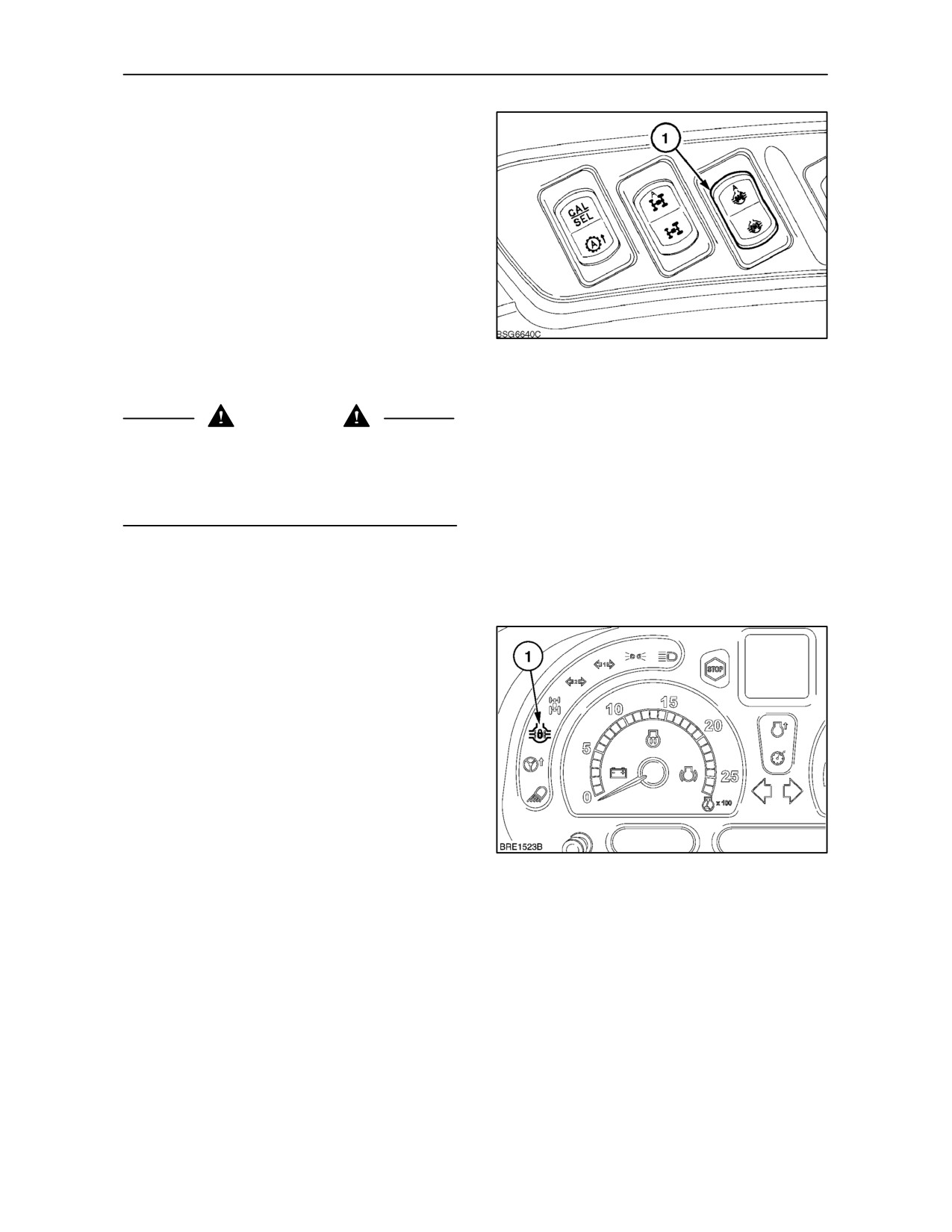
The differential locks are controlled by a spring
centered rocker switch on the console to the right of
the seat.
The differential lock(s) may be operated in manual
mode or automatic mode. To confirm mode selected,
150
the appropriate symbol on the switch will illuminate
when engaged.
WARNING
Avoid using the differential lock at speeds above
8km/h (5 MPH) and never at speeds above 15 km/h
(9 MPH) or at any time when turning the tractor.
When engaged, the differential lock will make
steering the tractor very difficult.
IMPORTANT: If wheel spin is encountered, reduce
engine speed before engaging the differential lock,
to avoid shock loads to the transmission.
Operating in Manual Mode
In slippery conditions, momentarily depress the
bottom of the switch (1) Figure 150 , to lock both
wheels together. The differential lock(s) will engage
and a warning light in the switch and on the
instrument panel (2) will light up.
When one or both brake pedals are applied or if the
switch is returned to the off
(central) position,
disengagement will occur and the warning lights in
the switch and instrument panel will go out.
Alternatively, depress the bottom of the switch again
to disengage the differential lock(s).
151
NOTE: The lock(s) will remain engaged until traction
at the wheels equalises.
2--102
SECTION 2 -- CONTROLS, INSTRUMENTS AND OPERATION
Operating in Automatic Mode (where fitted)
To engage both front and rear differential locks in
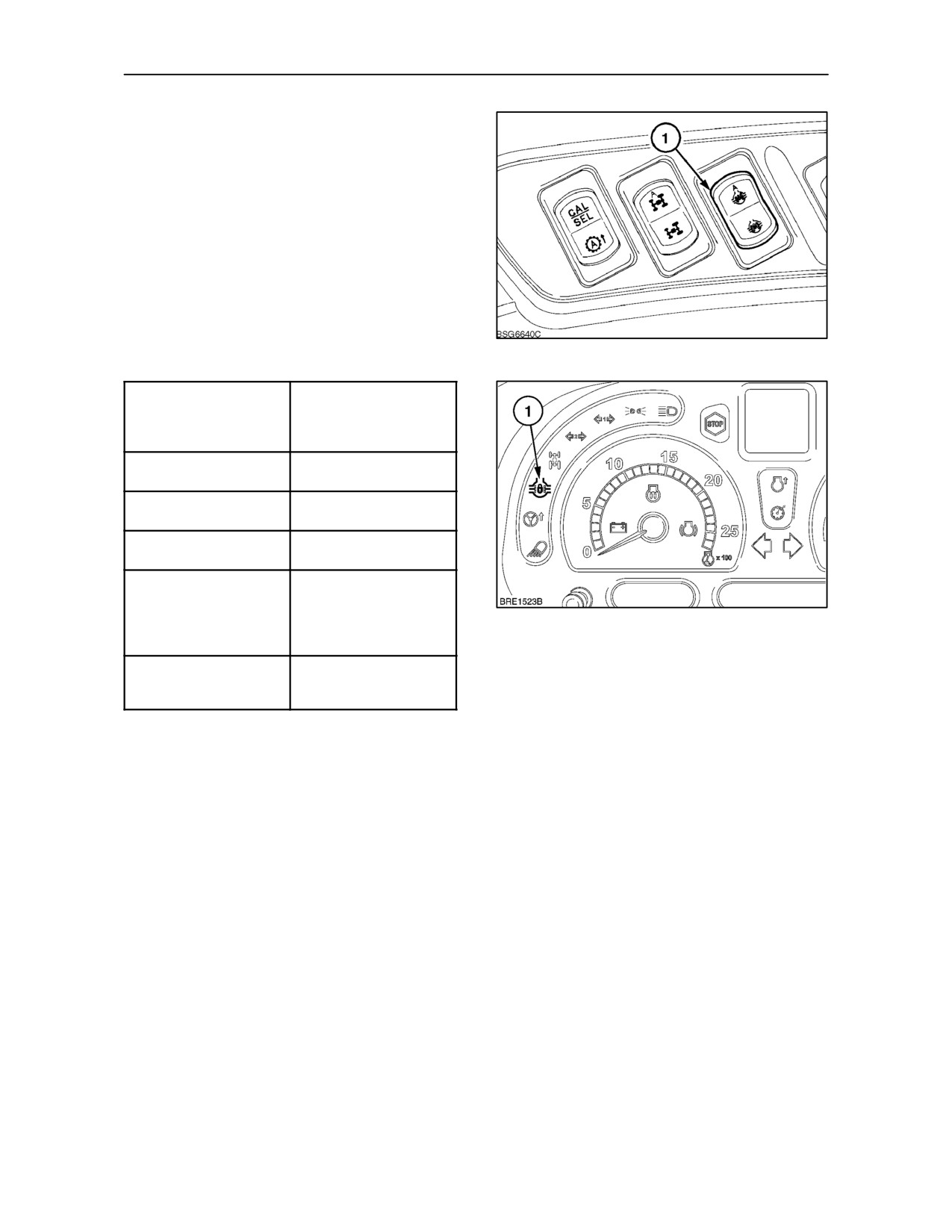
automatic mode, depress the top of the switch (1).
The warning light in the switch will illuminate. The
indicator light (1) Figure 153 on the instrument panel
will also illuminate but will only remain lit while the
differential locks are engaged.
In automatic mode, disengagement of the locks will
occur as follows:
152
Fast raise switch
Temporary
activated (to raise the
disengagement (will
rear 3--point hitch)
re--engage when 3--point
hitch is lowered
Either brake pedal is
Temporary
applied
disengagement
Both brake pedals are
Differential lock remains
applied simultaneously
engaged
Tractor speed exceeds
Differential locks will
15 Km/h (9 MPH)
permanently disengage
Front steering angle
Temporary
exceeds pre--set limits
disengagement (will
(where fitted)
re--engage when
153
steering angle is
reduced)
Momentarily depress the
Differential locks will
top of the differential lock
permanently disengage
rocker switch
NOTE: If the differential lock is active when the
key--start is turned off, it will remain active when the
key--start is switched on again.
2--103
SECTION 2 -- CONTROLS, INSTRUMENTS AND OPERATION
FOUR WHEEL DRIVE (where fitted)
Four wheel drive greatly improves traction in difficult
conditions. The drive to the front wheels is designed
to be engaged or disengaged with the tractor
stationary or moving.
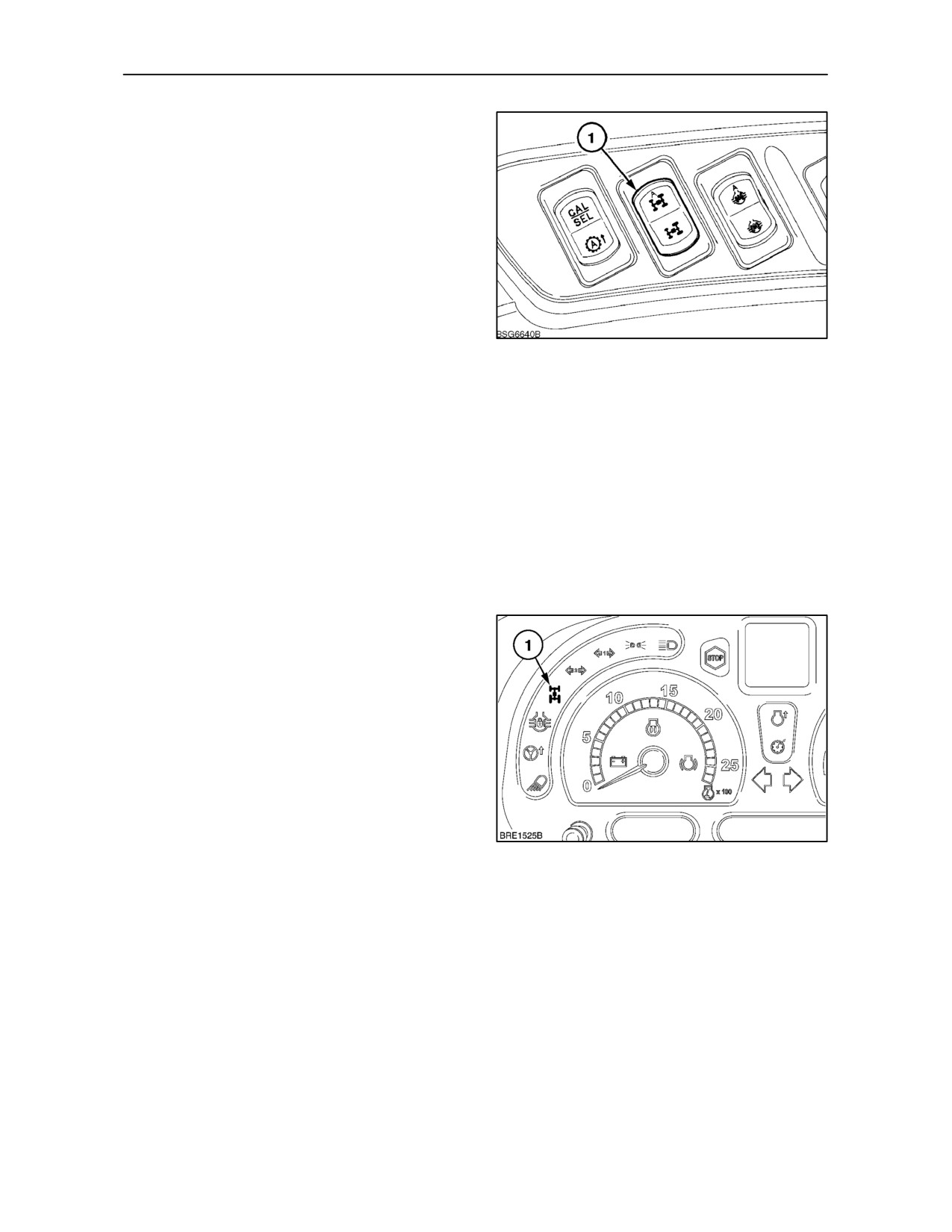
NOTE: The drive to the front wheels is actuated by
a three position rocker switch on the right--hand
control console. To confirm mode selected, the
appropriate symbol on the switch will illuminate when
engaged.
154
Operating in Manual Mode
Press the bottom of the switch to engage the drive to
the front wheels. Warning lights in the switch and
instrument panel will illuminate when four wheel drive
is engaged. To disengage four wheel drive return the
switch to the off (central) position.
NOTE: If four wheel drive is engaged when the
key--start is turned off, it will remain engaged when
the key--start is switched on again.
Operating in Automatic Mode (where fitted)
To engage automatic four wheel drive mode
momentarily depress the top of the four wheel drive
switch (1) Figure 154. The warning light in the switch
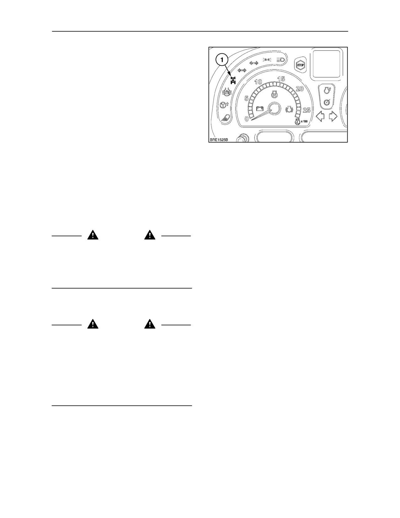
will illuminate. The indicator light (1) Figure 155 on
the instrument panel will also illuminate but will only
remain lit while four wheel drive is engaged.
Four wheel drive will remain permanently engaged
unless one of the following occurs:
• Wheel speed exceeds 20 Km/h (12.4 MPH).
Four wheel drive will re--engage when wheel
155
speed falls below 18 Km/h (11.1 MPH)
2--104
SECTION 2 -- CONTROLS, INSTRUMENTS AND OPERATION
NOTE: The following applies only to tractors fitted
with a steering angle sensor.
• Wheel speed falls below 10 Km/h (6.2 MPH) and
steering angle exceeds
30°
(21° with
SuperSteer). Four wheel drive will re--engage
when the steering angle is reduced.
• Wheel speed is between 10 and 20 Km/h (6.2
and 12.4 MPH) and steering angle exceeds 25°
(17° with SuperSteeer). Four wheel drive will
re--engage when the steering angle is reduced.
NOTE: The above steering angles are set during
156
manufacture, if an alternative angle setting is
required, consult your authorised dealer.
The indicator light (1) Figure 156 on the instrument
panel will also illuminate but will only remain lit when
four wheel drive is engaged.
NOTE: To avoid excessive tyre wear when travelling
on the public highway or any hard surface, it is
recommended that four wheel drive be disengaged.
WARNING
Tractors with four wheel drive engaged or
disengaged should not be allowed to overspeed by
towing or coasting downhill with clutch depressed or
transmission in neutral. This may cause loss of
control, personal injury to the operator or bystanders
or failure of the drive shaft.
NOTE: Keep the tractor in the same gear going
downhill as would be used when going uphill.
WARNING
Your tractor is equipped with very efficient,
hydraulically actuated rear wheel brakes. On four
wheel drive tractors the drive to the front axle is
automatically engaged, at speeds above 8.5 km/h
(5.2 MPH), when the brakes are applied, to provide
four wheel braking. Owners should be aware of the
effectiveness of four wheel braking which greatly
enhances braking performance. Care should be
taken during heavy braking, particularly if the rear of
the tractor is unballasted.
2--105
SECTION 2 -- CONTROLS, INSTRUMENTS AND OPERATION
TERRAGLIDE™ FRONT AXLE
SUSPENSION (where fitted)
The optional, self-levelling, front axle suspension will
provide improved stability, control, comfort and
traction. Terraglide is automatically activated each
time the tractor is started but will not function at
speeds below 1.5 k/mh (0.9 MPH).
When operating at speeds up to 12 k/mh (7.4 MPH),
the front axle suspension may be locked out if not
required. A warning light in the switch will indicate
lock out is engaged.
157
To lock out the suspension, press the top of the
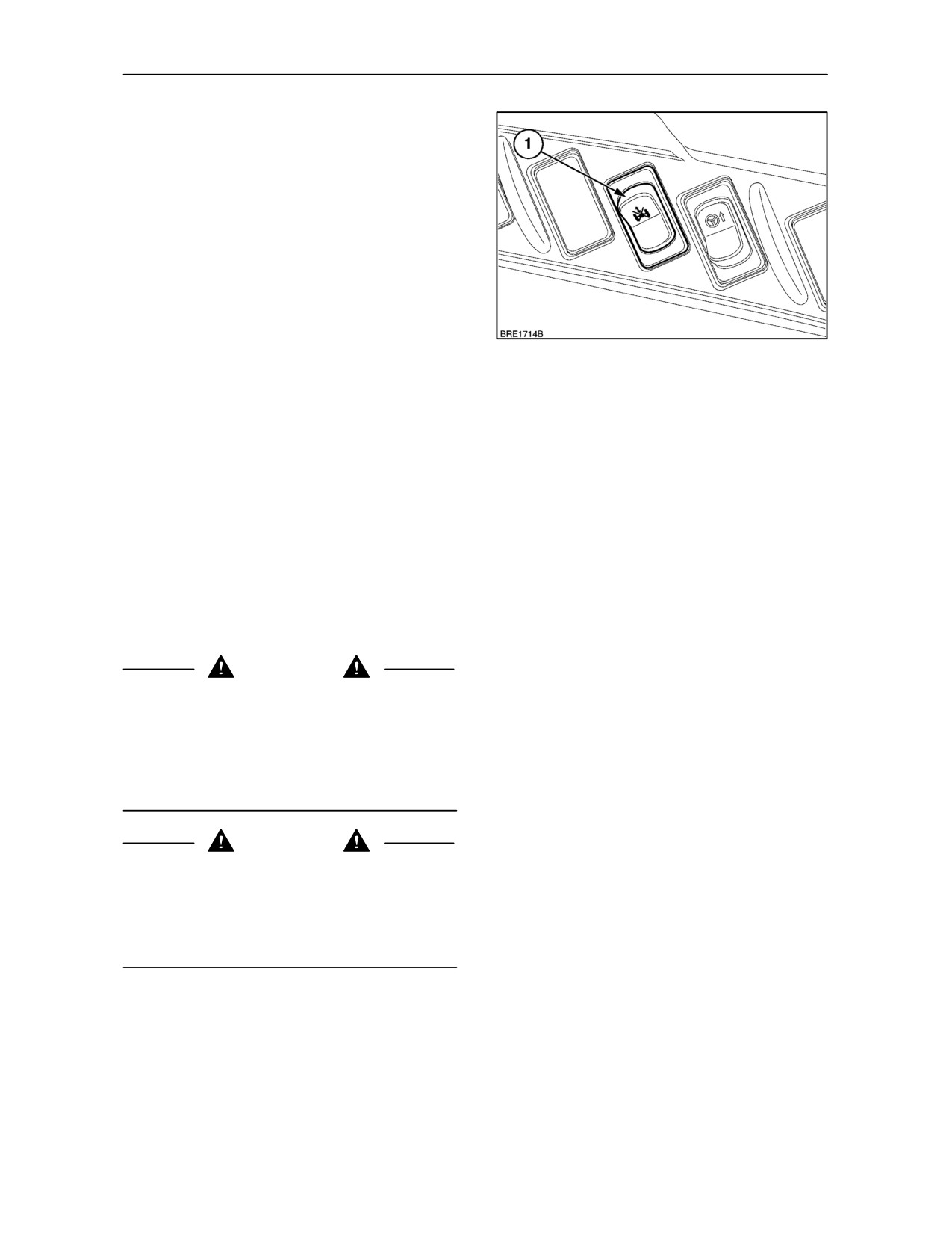
switch (1) on the right-hand control panel. Press the
top of the switch again to reactivate the suspension
facility.
At speeds above 12 k/mh (7.4 MPH), the suspension
will automatically re--engage, overriding axle lock
out. In this situation the warning light will remain on.
NOTE: Should the lock out switch warning light begin
to flash, this would indicate a malfunction of the
suspension system. Consult your authorised dealer.
IMPORTANT: See Ballasting and Tyres, page
3--136, regarding the use of front end weights with
front axle suspension.
WARNING
Hydraulic oil in the front axle suspension system
operates under very high pressure. Escaping
hydraulic oil under pressure can penetrate the skin
causing serious injury. Unqualified persons should
not attempt to disconnect any pipework in the front
axle hydraulic system. Failure to follow these
instructions can result in serious injury.
WARNING
If a transmission ratio is engaged, with the engine
running and the tractor supported on axle stands, the
self-levelling function of the suspension may cause
the axle to make corrections (move up and down).
The suspension should be locked out to maintain
stability.
2--106
SECTION 3
FIELD OPERATION
BEFORE OPERATING
CAUTION
Page
Subject
Before driving or operating the tractor, study the
safety precautions in Section 1 of this Manual.
Important Information
3--2
Boosting theTractor Battery
3--4
Read this section carefully for a thorough
Starting the Engine
3--5
understanding of operational requirements. Even if
you operate other tractors, you should thoroughly
Stopping the Engine
3--10
read this section of the manual and ensure that you
Fast Steer Operation
3--12
are familiar with the location and function of all the
features of the tractor.
Rear Power Take--Off
3--14
Front Power Take--Off and Hydraulic Lift
3--33
Do not start the engine or attempt to drive or operate
the tractor until you are fully accustomed with all the
Mechanical Lower Link Sensing Hydraulics
3--41
controls. It is too late to learn once the tractor is
Electronic Draft Control
3--47
moving. If in doubt about any aspect of operation of
the tractor, consult your authorised dealer.
Remote Control Valves
3--59
Electro--Hydraulic Remote Control Valves
3--69
See Section 4 for lubrication and maintenance
requirements. Tractor specifications will be found in
Additional Oil Supply for Remote Services
3--81
Section 8.
Three-point Linkage
3--83
This section is split into a number of different
Quick Hitch
3--90
subjects, as follows. A comprehensive index is
provided at the end of this manual.
Linkage Stabilisers
3--92
Drawbars and Towing Attachments
3--97
PROGRAMMING TRACTOR FUNCTIONS
Hydraulic Trailer Brakes
3--113
Your tractor utilises two memory facilities to control
Air--Operated Trailer Brakes
3--115
and memorise settings for the various electronic
functions. The operating memory temporarily stores
Front Wheel Track Adjustment
3--121
setting adjustments made while operating the tractor
Rear Wheel Track Adjustment
3--128
and these are uploaded to the main memory when
you key--off (engine stop).
Ballasting and Tyres
3--135
If you key--off and key--on again too quickly as data
is being uploaded, some of it may be lost or
corrupted.
If you have made changes to any memorised
settings while operating the tractor, pause for five
seconds between key--off and key--on to allow the
data to upload from the operating memory to the
main memory. Once uploaded, the new settings will
remain unchanged until they are re--programmed.
3--1
SECTION 3 -- FIELD OPERATION
RUNNING--IN PROCEDURE
PRE-OPERATION CHECKS
Your new tractor will provide long and dependable
Before operating the tractor, ensure that you are
service if given proper care during the 50 hour
thoroughly familiar with the location and operation of
running--in period and if serviced at the
the controls.
recommended intervals.
Perform all daily lubrication and maintenance
Avoid overloading the engine. Operating in too high
operations in accordance with Section 4.
a gear under heavy load may cause excessive
engine overloading. Overloading occurs when the
After completing the daily maintenance operations,
engine will not respond to a throttle increase.
perform a walk around visual inspection of the
Do not operate without a load on the engine. This can
tractor. Pay particular attention to the following
items:
be as harmful to the engine as overloading. Vary the
type of operation undertaken so that the engine is
subjected to heavy as well as light loads during the
• Fan belt for cracks
running--in period.
• Engine area for accumulation of debris
Use the lower gear ratios when pulling heavy loads
and avoid continuous operation at constant engine
• Hoses, lines and fittings for leaks or damage.
speeds. Operating the tractor in too low a gear with
a light load and high engine speed will waste fuel. You
• Tyres for damage
will save fuel and minimise engine wear by selecting
the correct gear ratio for each particular operation.
• Hardware for looseness
Check the instruments and warning lights frequently
and keep the radiator and various oil reservoirs filled
• Driveline and hydraulic pump areas for leaks or
to the recommended levels.
debris accumulation
Make any necessary repairs before using the tractor.
PRESSURE WASHING THE TRACTOR
Your tractor is equipped with a number of electronic
control units
(ECU’s) that are linked to various
sensors throughout the vehicle. The ECU’s control,
monitor, and provide information relating to engine,
transmission, P.T.O. and hydraulic functions.
It is very important therefore, when cleaning the
tractor body or chassis with a high pressure water jet,
that care should be taken not to aim the water jet
directly at any electrical component, wiring harness
or connector.
3--2
SECTION 3 -- FIELD OPERATION
TOWING THE TRACTOR
CARRYING THE TRACTOR ON A
TRANSPORTER
IMPORTANT: The tractor should only be towed a
short distance, such as out of a building. Do not tow
Transport the tractor with all four wheels on a flat bed
on roadways or as a method of transport.
trailer or truck. Securely chain the tractor to the
transporter.
IMPORTANT: If it is necessary to tow the tractor, all
IMPORTANT: Do not chain around the four wheel
gear levers must be moved to the neutral position
drive shaft, steering cylinders, front wheel drive axle
before stopping the engine otherwise damage to
or other components that could be damaged by
transmission components may occur during towing.
contacting the chain or by heavy loading.
If creeper gears (reduction gear set) are fitted, then
the selector control must be in the off position.
Use the drawbar or drawbar hanger for a rear tie
down point.
Use a strong chain when towing the tractor. Tow the
tractor from the rear using only the drawbar, rear tow
IMPORTANT: Cover the silencer outlet so that the
hitch or the three-point hitch. Tow the tractor from the
wind does not spin the turbocharger and damage the
front using the tow pin in the front weights or front
bearings. Turbocharger turbine freewheeling
support. Have an operator steer and brake the
(turning without engine running) must be avoided
tractor.
since lubrication will not be provided to the
turbocharger bearings.
To avoid damaging the transmission or other
Where road speeds in excess of 50 Km/h (31 MPH)
components that turn but are not lubricated during
are likely to occur when transporting the tractor, it is
towing, observe the following:
advisable to secure the high visibilty roof panel with
ties to prevent it from opening.
• Only tow a short distance
• Keep speed below 5 MPH (8 km/h)
• If possible, run the engine to provide lubrication
to the transmission and power steering.
CAUTION
Do not tow the tractor faster than 8 Km/h (5 MPH).
The steering is much slower and steering wheel
effort is much greater without the engine running.
WARNING
1
Do not use cables or rope to tow the tractor. If the
cable or rope breaks or slips, it may whip with
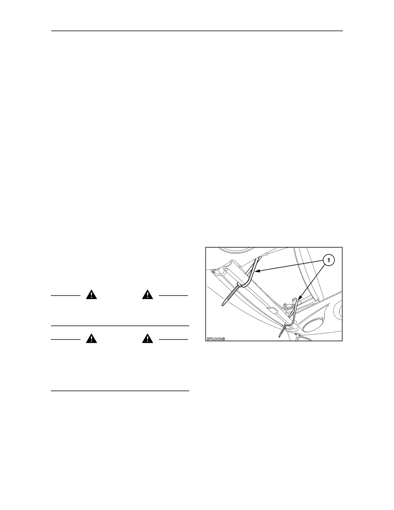
Secure both handles to the sunvisor support using
sufficient force to cause serious injury. When using
a flexible strap such as a cable tie (1) as shown in the
a chain, attach the chain with the hook open side
illustration above. Do not use wire or metal straps as
facing up. If the hook slips, it will drop down instead
these may damage the paintwork.
of flying up.
NOTE: Four wheel drive will be engaged if the engine
is not running, regardless of the position of the 4WD
activation switch.
3--3
SECTION 3 -- FIELD OPERATION
BOOSTING THE TRACTOR BATTERY
Using Remote Jump Terminals
WARNING
Always sit in the driver’s seat to operate the starter
motor. If the key-start switch is by-passed and the
tractor has been left in gear, sudden and unexpected
movement of the tractor or a tractor runaway may
result which could cause serious injury. Wear eye
1
protection when starting the tractor with jump leads
or when charging the battery.
If it is necessary to use jump leads (booster cables)
to start the tractor, use only heavy duty leads and
2
proceed as follows:
50032874
2
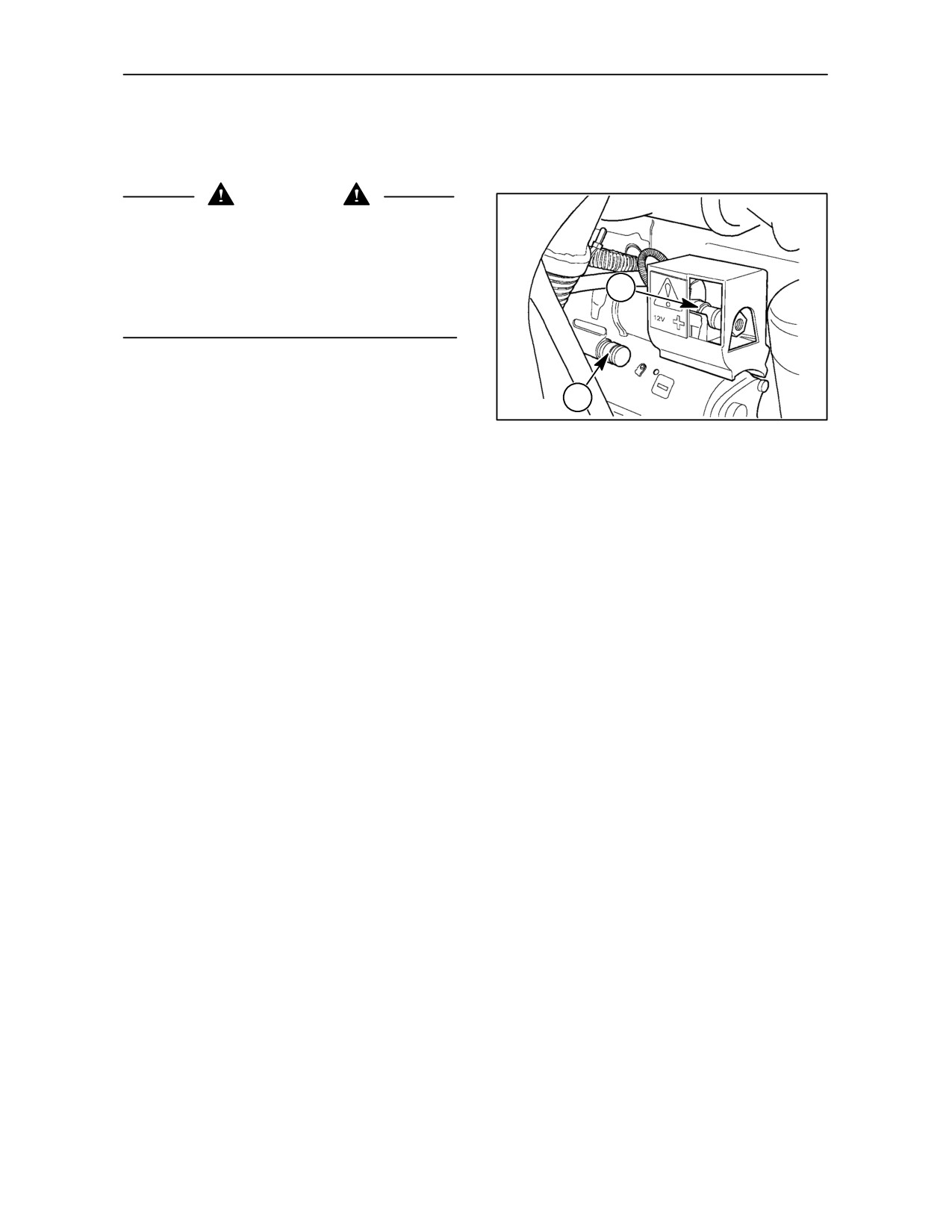
The remote jump terminals, installed on the
right-hand side of the engine, provide an easy
method of boosting the tractor battery without having
to remove the battery cover.
The positive terminal (1), is attached to the starter
solenoid, and is encased in a plastic housing.
The negative terminal (2) attaches to the upper
mounting bolt of the starter.
Connect one end of red jump lead, to the positive,
(+), remote jump terminal, (1), and the other end to
the positive, (+), terminal of the auxiliary battery.
Connect one end of black jump lead, to the negative,
(--), remote jump terminal,(2), and the other end to
negative, (--), terminal of auxiliary battery.
When the engine starts allow it to run at idle speed,
turn on all electrical equipment (lights, etc.) then
disconnect the jump leads in the reverse order to the
connecting procedure. This will help protect the
alternator from possible damage due to extreme load
changes.
3--4
SECTION 3 -- FIELD OPERATION
Turn off all electrical equipment not required and run
the tractor engine until the battery is fully charged.
IMPORTANT: When using an auxiliary battery to
start the engine, ensure that the polarity of the jump
leads is correct -- positive to positive, negative to
negative, otherwise the alternator may be damaged.
Only use an auxiliary battery if the tractor batteries
are discharged. Excessive amperage (above 1600
cca) may damage the starting motor. In the event of
the batteries being severely discharged, such that
terminal voltage is below 7 volts, recovery will require
a special charging procedure. See your authorised
dealer.
STARTING THE ENGINE
Before starting the engine, always carry out the
following procedure:
• Sit in the driver’s seat.
• Ensure that the parking brake is firmly applied.
• Ensure that all gearshift levers are in neutral.
• Ensure the shuttle lever is in neutral.
• Ensure that the P.T.O. knob is in the ‘off’ position.
• Place the remote control valve levers in the
neutral position.
• Move the hydraulic lift control lever fully forward.
WARNING
Check the area beneath the equipment to ensure
that no injury or damage will be caused when
equipment is lowered.
• Depress and hold the clutch pedal.
IMPORTANT: The high operating speed of the
turbo-charger makes it essential that adequate
lubrication is assured when the engine is started.
Therefore, idle the engine at
1000 rev/min for
approximately one minute before driving the tractor.
3--5
SECTION 3 -- FIELD OPERATION
THERMOSTART COLD START AID
(where fitted)
WARNING
Your tractor is equipped with an electronic cold
weather starting aid. Do not use ether with the cold
start aid installed. It will explode in the intake
manifold. If any difficulty is experienced when trying
to start your tractor in cold temperatures, consult
your authorised dealer.
The Thermostart, which is effective in ambient
temperatures down to --18° C (0° F), consists of a
heating element installed in the intake manifold.
When operated by the key--start switch, the
Thermostart will ignite fuel in the inlet manifold,
heating the indrawn air prior to entering the
combustion chamber.
A warning light on the instrument panel will illuminate
to confirm operation.
If
temperatures below
--18° C
(0° F) are
encountered, a block coolant heater is available as
an accessory. The block coolant heater is effective
in ambient temperatures down to --29° C (--20° F)
when used in conjunction with the Thermostart.
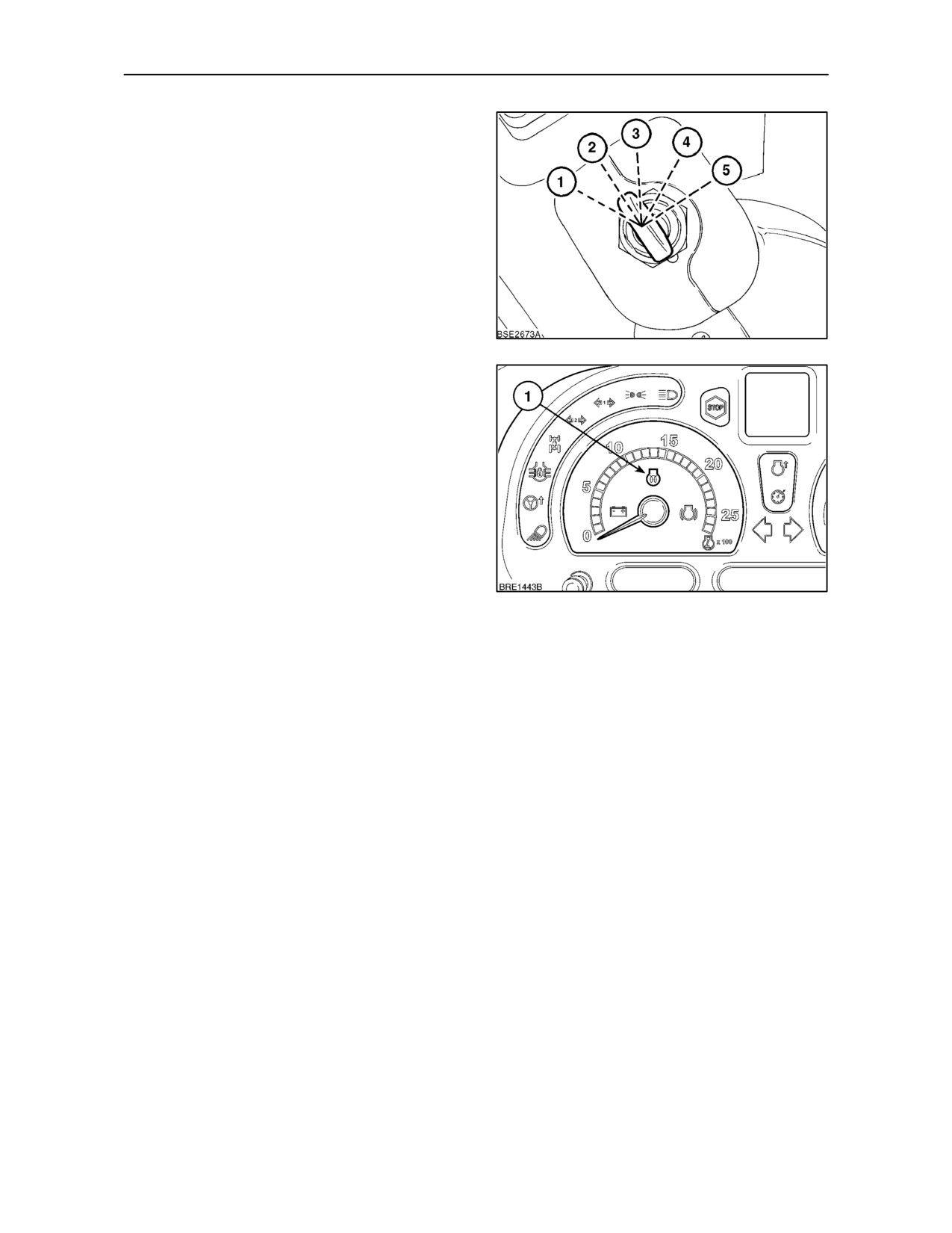
Key Start Switch (with Thermostart)
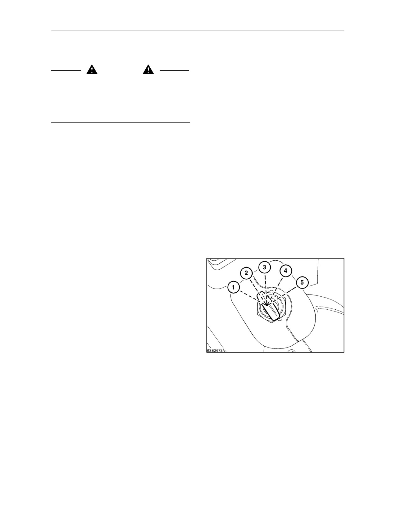
A five-position key-start switch is installed. The
key-start switch positions are as follows:
Position 1
Thermostart activated
Position 2
Off
Position 3
Accessories on
Position 4
Warning lights and instruments on
Position 5
Starter motor engaged
IMPORTANT: Never push or tow the tractor to start
the engine. Use an auxiliary battery and jump leads.
3
NOTE: Neutral start switches prevent operation of
the starting motor unless the shuttle lever is in the
neutral (N) position.
3--6
SECTION 3 -- FIELD OPERATION
Starting in cold weather (with cold engine)
• Open the hand throttle halfway and turn the
key-start switch anti--clockwise to position (1)
and hold.
• An indicator light (1) Figure 5, will illuminate to
show that the Thermostart heater is active.
• When the light extinguishes, turn the key fully
clockwise to position (5). Crank the engine until
it starts but do not operate the starting motor for
more than 60 seconds.
4
NOTE: Providing that the key is turned to the crank
position (5) within 3 seconds of the indicator light
going out, the Thermostart will be re--activated
during cranking.
• If the engine fails to start, repeat the foregoing
procedure. If the engine still fails to start, allow
the battery to recover for 4 -- 5 minutes then
repeat the procedure.
• When the engine starts, return the throttle to the
idle position and check that all warning lights
extinguish and gauge readings are normal.
5
Starting in warm weather or when the engine is
hot
• Open the hand throttle halfway and turn the
key-start switch fully clockwise to position (5) to
operate the starting motor. Crank the engine until
it starts but do not operate the starting motor for
more than 60 seconds.
NOTE: Once the starter motor has been operated,
it is necessary to return the key-start switch back to
the ‘off’ position before the starting motor can be
re-activated.
• Return the throttle to the idle position and check
that all warning lights extinguish and gauge
readings are normal.
3--7
SECTION 3 -- FIELD OPERATION
GRID HEATER COLD START AID
(where fitted)
WARNING
If your tractor is equipped with a Grid Heater
electronic cold weather starting device, do not use
ether as a starting aid. It will explode in the intake
manifold. If any difficulty is experienced when trying
to start your tractor in cold temperatures, consult
your authorised dealer.
The grid heater, which is effective in ambient
temperatures down to --18° C (0° F), consists of a
heating element installed in the intake manifold.
Operation of the grid heater is automatic when the
the engine coolant temperature falls to 0° (32° F ) or
below.
A warning light on the instrument panel will illuminate
to confirm operation.
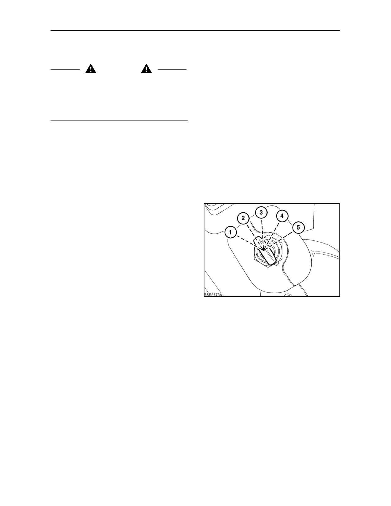
Key Start Switch (with Grid Heater)
A five-position key-start switch is installed. The
key-start switch positions are as follows:
Position 1
Not used
Position 2
Off
Position 3
Accessories on
Position 4
Warning lights, instruments and
Grid Heater on
Position 5
Grid heater on, starter motor
engaged
IMPORTANT: Never push or tow the tractor to start
6
the engine. Use an auxiliary battery and jump leads.
NOTE: Neutral start switches prevent operation of
the starting motor unless the shuttle lever is in the
neutral (N) position.
3--8
SECTION 3 -- FIELD OPERATION
Starting in cold weather (with cold engine)
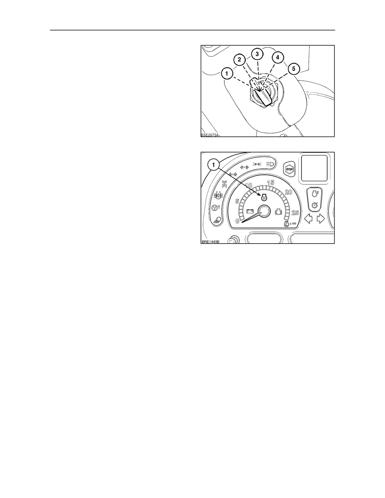
• Open the hand throttle halfway and turn the
key-start switch clockwise to position (4). An
indicator light
(1) Figure 8, on the instrument
panel will illuminate for 10 to 15 seconds to show
the grid heater has been activated.
• When the light extinguishes, turn the key fully
clockwise to position (5). Crank the engine until
it starts but do not operate the starting motor for
more than 60 seconds.
NOTE: If cranking is not carried out within
30
seconds of the light extinguishing, turn the key--start
7
tothe’off’position, pauseandre--start thesequence.
• If the engine fails to start, repeat the foregoing
procedure. If the engine still fails to start, allow
the battery to recover for 4 -- 5 minutes then
repeat the procedure.
• When the engine starts, return the throttle to the
idle position and check that all warning lights
extinguish and gauge readings are normal.
If
temperatures below
--18° C
(0° F) are
encountered, a block coolant heater is available as
an accessory. The block coolant heater is effective
in ambient temperatures down to --29° C (--20° F)
when used in conjunction with the grid heater.
8
Starting in warm weather or when the engine is
hot
• Open the hand throttle halfway and turn the
key-start switch fully clockwise to position (5) to
operate the starting motor. Crank the engine until
it starts but do not operate the starting motor for
more than 60 seconds.
NOTE: Once the starter motor has been operated,
it is necessary to return the key-start switch back to
the ‘off’ position before the starting motor can be
re-activated.
• Return the throttle to the idle position and check
that all warning lights extinguish and gauge
readings are normal.
3--9
SECTION 3 -- FIELD OPERATION
STOPPING THE ENGINE
IMPORTANT: Before stopping, idle the engine at
1000 rev/min for approximately one minute. This will
allow the turbo--charger and manifold to cool and
prevent possible distortion of components.
To stop the engine, carry out the following procedure:
• Sit in the driver’s seat.
• Close the throttle.
• Ensure that the parking brake is firmly applied.
• Ensure that all gearshift levers are in neutral.
• Ensure the P.T.O. is disengaged.
• Place the remote control valve levers in the
neutral position.
• Lower 3 point hitch mounted equipment to the
ground.
• Turn the key--start switch off -- position (2).
AUTOMATIC ENGINE SHUTDOWN
(where fitted)
Automatic engine shutdown is standard on tractors
equipped with the optional Enhanced Keypad.
The system monitors four key areas that are critical
to the safe operation of engine and driveline and, in
the unlikely event that one or more of these reaches
a critical level, the engine will be shut down.
• Engine oil pressure falls below safe limits.
• Engine coolant temperature exceeds safe limits.
• Driveline oil pressure falls below safe limits.
• Driveline oil temperature rises above safe limits.
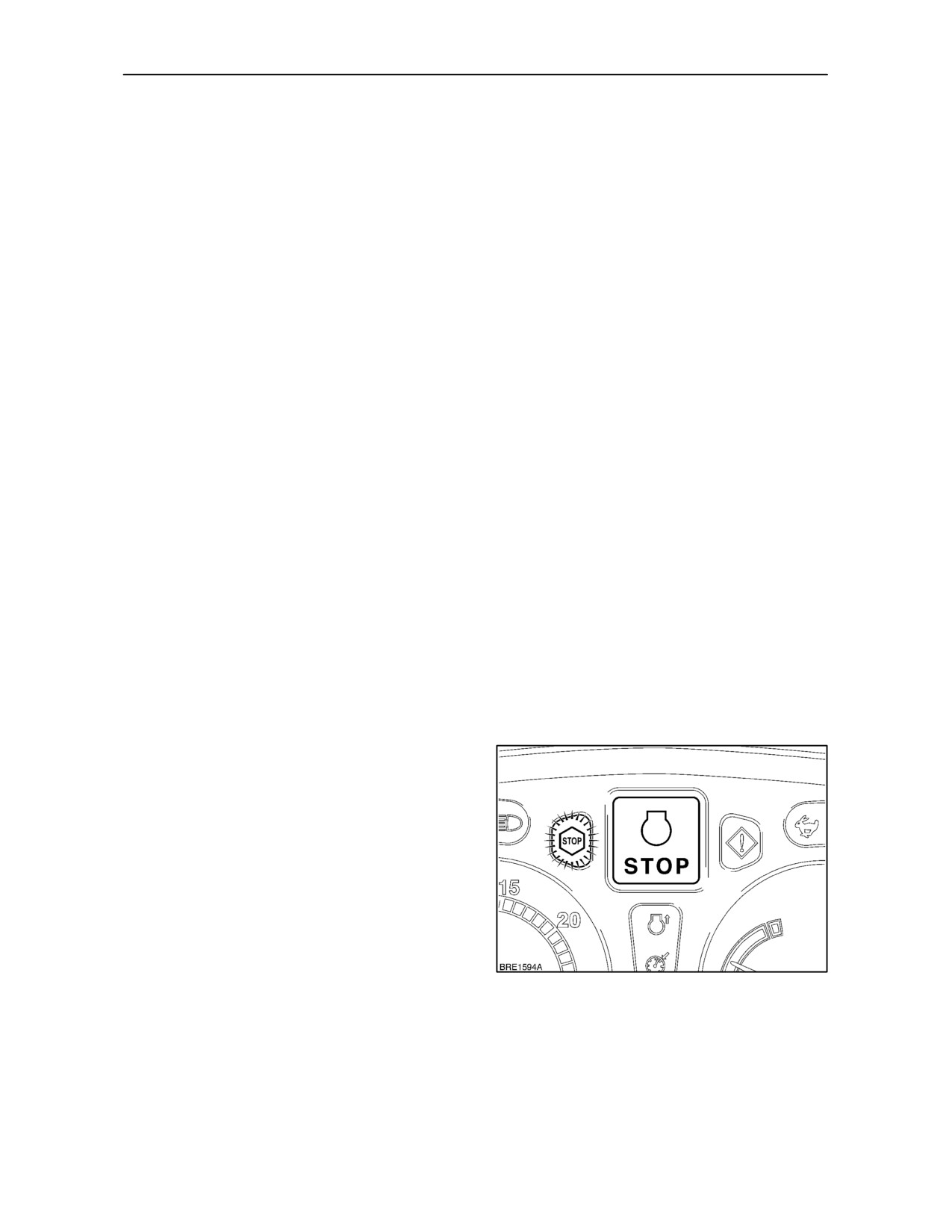
Prior to engine shutdown the red Stop light will start
to flash and the critical alarm will sound. In addition,
the engine fault warning and malfunction symbols
will flash alternately in the Dot Matrix Display. If, after
30 seconds, the operator has not stopped the
engine, the automatic shutdown feature will be
activated and the engine will be shut down.
9
3--10
SECTION 3 -- FIELD OPERATION
After the engine has shut down, the red Stop light will
remain on but the alarm will cease to sound. Both
engine and malfunction symbols will continue to flash
alternately.
The automatic engine shutdown function may be
programmed by your authorised dealer to operate in
one of three modes:
1. No engine shutdown. In this mode the engine is
not capable of automatic shutdown.
2. Always engine shutdown. The engine will
shutdown at any time if one or more of the
monitored conditions reaches a critical level.
3. Stationary engine shutdown. The engine will
shutdown only during stationary operations if
one or more of the monitored conditions reaches
a critical level.
IMPORTANT: Before attempting to start an engine
that has automatically shutdown, check for, and
rectify, the fault that caused the engine to be
stopped.
3--11
SECTION 3 -- FIELD OPERATION
FAST STEER (where fitted)
The optional Fast Steer system is designed to
provide fast steering response when required i.e.
when operating with a front loader.
From the straight ahead position, Fast Steer will
provide full right or left hand steering lock with less
than a 10° movement of the steering wheel.
IMPORTANT: Before travelling on the public
highway Fast Steer must be de--activated and
normal steering re--instated. To check normal
steering operation, turn the wheel fully from lock to
10
lock before starting your journey.
NOTE: Fast Steer will not operate if the tractor speed
is above 10 K/mh (6.2 MPH).
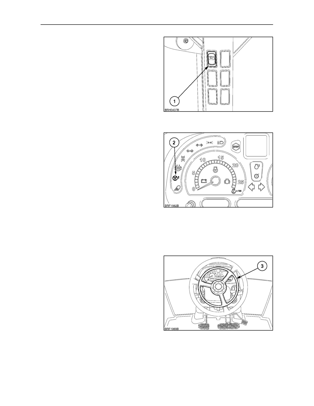
To activate the Fast Steer function, depress the
isolator switch (1). A warning light in the switch will
illuminate to confirm activation.
To operate Fast Steer, depress and hold the centre
ring (3) on the steering wheel, to disengage, release
the ring. With the centre ring depressed, the indicator
light (2) will illuminate on the instrument panel. It will
extinguish when the centre ring is released.
NOTE: If the isolator switch (1) is left in the ’ON’
11
position at engine key--off, then Fast Steer will be
de--activated at key--on. The isolator switch warning
light will not illuminate and the indicator light (2) will
flash if the centre ring is depressed. To re--activate
Fast Steer turn the isolator switch ’OFF’ and then
’ON’.
Fast Steer can only be operated if the following three
conditions are met.
1. The isolator switch is in the ON position and the
switch warning light is illuminated.
2. The speed of the tractor is below 10 K/mh
(6.2 MPH)
3. The transmission oil temperature is above 5° C.
NOTE: Attempting to use the Fast Steer function
without meeting all the above conditions, will cause
the indicator light (2) to flash.
12
3--12
SECTION 3 -- FIELD OPERATION
NOTE: If tractor speed exceeds 10 K/mh (6.2 MPH)
with Fast Steer in operation, it will be disengaged and
the indicator light (2) will flash.
NOTE: Where the transmission oil temperature is
low and Fast Steer is to be used, it is recommended
to turn the steering wheel twice, from full lock to full
lock, before commencing Fast Steer operation.
Fast Steer will be disabled if a fault occurs. Should
the system become disabled, an audible warning will
sound and an error code will appear in the Dot Matrix
Display. If the fault is of a critical nature, the ’STOP’
warning lamp will also flash on the instrument panel,
13
consult your authorised dealer.
To re--activate Fast Steer, turn the isolator switch (1)
’OFF’, correct the fault, and then turn the isolator
switch ’ON’.
IMPORTANT: To promote safe operation of Fast
Steer, it is advised that the operator become familiar
with the system before operating in the field.
3--13
SECTION 3 -- FIELD OPERATION
REAR POWER TAKE--OFF
Description
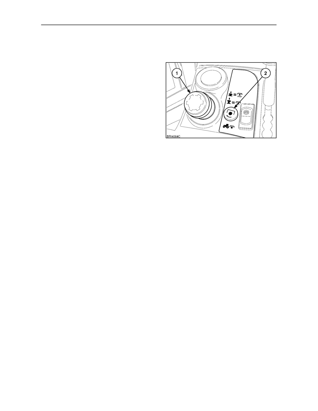
The P.T.O. is engaged and disengaged by means of
a knob (1) on the right-hand console. The adjacent
warning light (2) will illuminate when the P.T.O. is
engaged.
Four types of rear P.T.O. system are available,
dependent upon tractor model and country.
a) Two--speed P.T.O. with inter-changeable output
shafts.
b) Two--speed,
shiftable
P.T.O.
with
inter--changeable output shafts and the option of
fender--mounted switches for stationary P.T.O.
14
work.
c) Three--speed,
shiftable
P.T.O.
with
inter-changeable output shafts and the option of
fender-mounted switches for stationary P.T.O.
work.
d) Three--speed ground drive P.T.O., available in
conjunction with three speed shiftable P.T.O.
above.
An automatic ‘soft start’ facility is provided on all
models to permit easy start up of heavy, high inertia,
P.T.O.--driven equipment.
Soft start modulates P.T.O. clutch torque over the
first 5 seconds of engagement to provide a slower,
gradual take up of the drive.
NOTE: Soft start only operates at engine speeds of
1800 rev/min and below. Above this speed, normal
P.T.O. engagement will occur.
3--14
SECTION 3 -- FIELD OPERATION
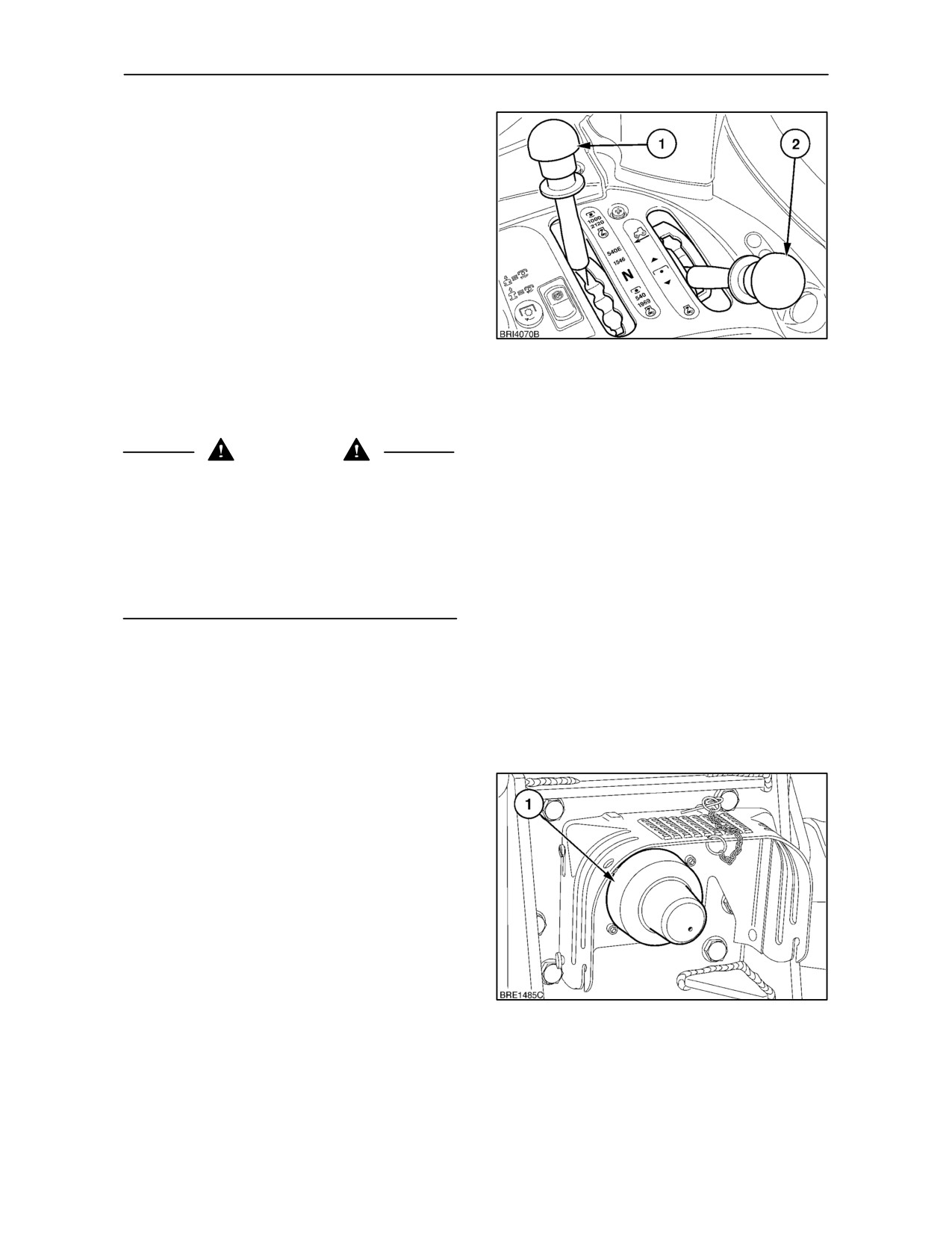
With shiftable P.T.O., a range lever is provided. The
lever is used to select one of two or three P.T.O.
speed ranges to provide power or economy. The
range lever (1), is located at the rear of the right-hand
console.
Ground drive P.T.O. is available, in conjunction with
3--speed, shiftable P.T.O., on all models. As
suggested by the name, ground drive P.T.O. speed
is directly related to rotation of the rear wheels rather
than engine speed. When ground drive P.T.O. is
installed, a second lever (2) is provided.
Three ground speed ranges are provided, selected
15
by means of the P.T.O. range lever (1). The lever (2)
is used to select ground drive.
ATTACHING P.T.O. DRIVEN EQUIPMENT
CAUTION
Before attaching or detaching equipment or
changing the P.T.O. shaft:
• Firmly apply the parking brake.
• Ensure that all gearshift levers are in neutral.
• Disengage the P.T.O. (knob fully down) and wait
until the P.T.O. and equipment stops. Switch off
the engine before getting off the tractor.
With the engine stopped, the P.T.O. brake is released
and the shaft may be turned by hand to aid
implement shaft alignment.
Mount or hitch the equipment to the tractor as
outlined in THREE--POINT LINKAGE on page 3--83.
The P.T.O. guard serves as a support for drive-line
shields used with P.T.O.-driven equipment and
provides for your safety. Do not modify the guard. A
plastic P.T.O. cap (1) is also supplied and should
always be installed over the shaft when the P.T.O. is
not in use.
16
3--15
SECTION 3 -- FIELD OPERATION
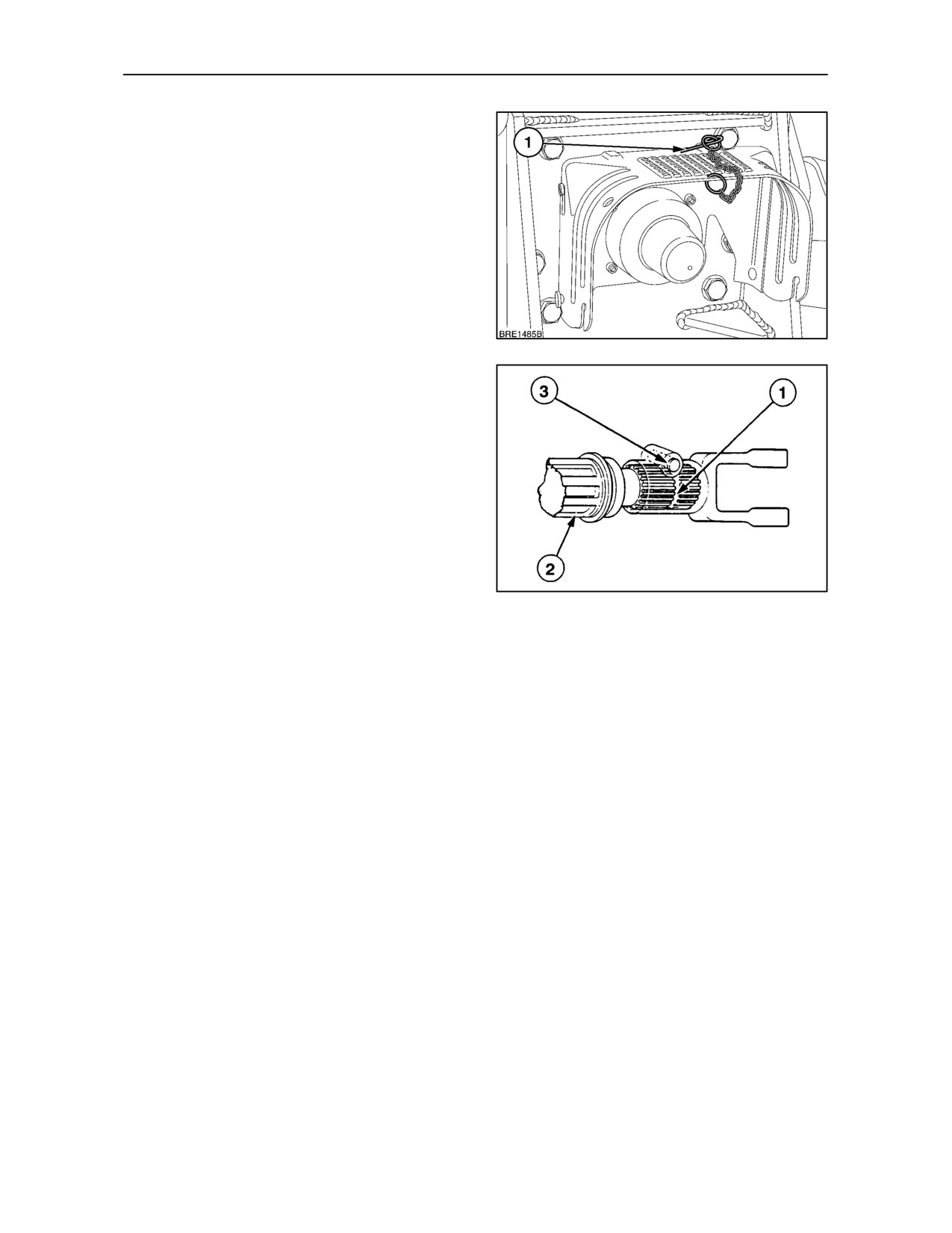
A flip-up P.T.O. guard is fitted as standard. Remove
the ’R’ clip (1) from the locating pin and slide the
guard upwards to clear the pin. Rotate the guard to
gain access to the P.T.O. shaft. A second locating pin
allows the guard to be fixed at 45° if required.
To connect P.T.O.-driven equipment to the P.T.O.
shaft, tilt the guard up for access. Pull the plastic cap
from the shaft and store it in the tractor toolbox.
NOTE: Tractors with slider type, vertically adjustable
drawbars have a flip--up P.T.O. guard plate fixed to
the slider frame. See ’Slider Frame Drawbars’ in
Section 7.
17
Attach the implement to the P.T.O. shaft, ensuring
that the implement driveshaft coupler lock pin (3) or
detent balls engage the groove in the P.T.O. shaft (2).
If the coupler does not have a locking arrangement,
pin the coupler to the shaft. Lower the flip-up guard
and replace the ’R’ clip.
IMPORTANT: After attaching mounted equipment,
carefully raise and lower using Position Control and
check clearances and P.T.O. shaft slide range and
articulation. When attaching trailed equipment,
ensure that the drawbar is correctly set.
18
3--16
SECTION 3 -- FIELD OPERATION
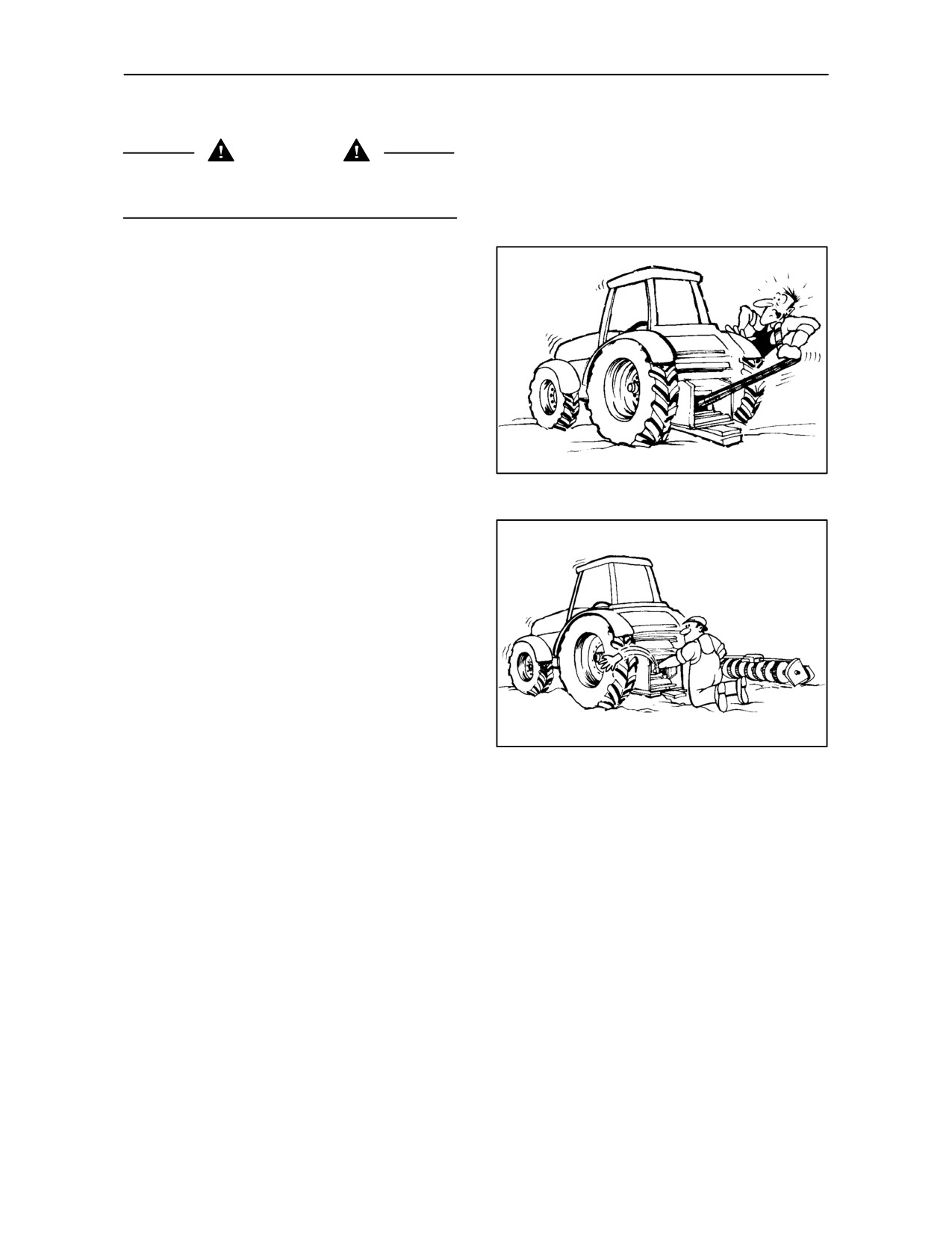
P.T.O. OPERATING PRECAUTIONS
WARNING
Whenever operating P.T.O. equipment, observe the
following precautions:
•
Check that you are using the correct P.T.O.
speed for the implement. Follow the instructions
in the equipment operator’s manual.
•
Ensure that the P.T.O. guard is installed when
using P.T.O. driven equipment.
•
Do not wear loose clothing when operating
P.T.O. driven equipment.
•
Firmly apply the parking brake, place all
gearshift levers in neutral and block all four
wheels before operating any stationary P.T.O.
equipment.
19
•
Do not approach, clean or adjust P.T.O. driven
equipment while the tractor engine is still
running. Disengage the P.T.O. (knob fully down)
and wait until the P.T.O. and equipment stops.
Switch off the engine before getting off the
tractor.
•
With the engine stopped, the P.T.O. brake is
released and the shaft may be turned by hand to
aid the installation or removal of the implement
P.T.O. shaft.
20
3--17
SECTION 3 -- FIELD OPERATION
TWO and THREE--SPEED P.T.O. SYSTEMS
General Information
Generally speaking, P.T.O. driven equipment not
having a high power requirement is designed to run
at 540 P.T.O. rev/min and will have a 6--spline female
coupling. A P.T.O. shaft speed of 540 rev/min is
obtained at an engine speed of 1970 rev/min.
Equipment having a high power requirement is
designed to operate at 1000 P.T.O. rev/min and will
be provided with a 21--spline female coupling. With
the 21--spline shaft installed, run the engine at 2120
rev/min to provide a P.T.O. speed of 1000 rev/min.
Equipment that requires very low power to operate
may be run in the alternative P.T.O. speed range at
a lower engine speed with a consequent reduction in
fuel consumption and engine wear.
Tractors with 3--speed P.T.O. have the advantage of
running low power 540 P.T.O. driven equipment at a
reduced engine speed by selecting 540E on the
lever. See page 3--24 for P.T.O. and engine speeds.
IMPORTANT: Implements with a high power
requirement should be operated with the
1000
rev/min. P.T.O. (21--spline shaft). If it is necessary to
use the 6--spline shaft (at 540 rev/min.) to operate
implements having a power requirement of more
than
75
horsepower, then it is strongly
recommended that the implement is fitted with a slip
clutch to avoid damage to the P.T.O. output shaft and
other tractor components.
NOTE: When required, change the P.T.O. shaft to
suit the operation and equipment in use, as
described under ‘Changing the P.T.O. Output Shaft’
on page 3--31 .
3--18
SECTION 3 -- FIELD OPERATION
TWO--SPEED P.T.O. WITH REVERSIBLE
OUTPUT SHAFT (where fitted)
Tractors with a reversible shaft P.T.O. system will be
supplied with a single output shaft having 6 and 21
splines.
Operating
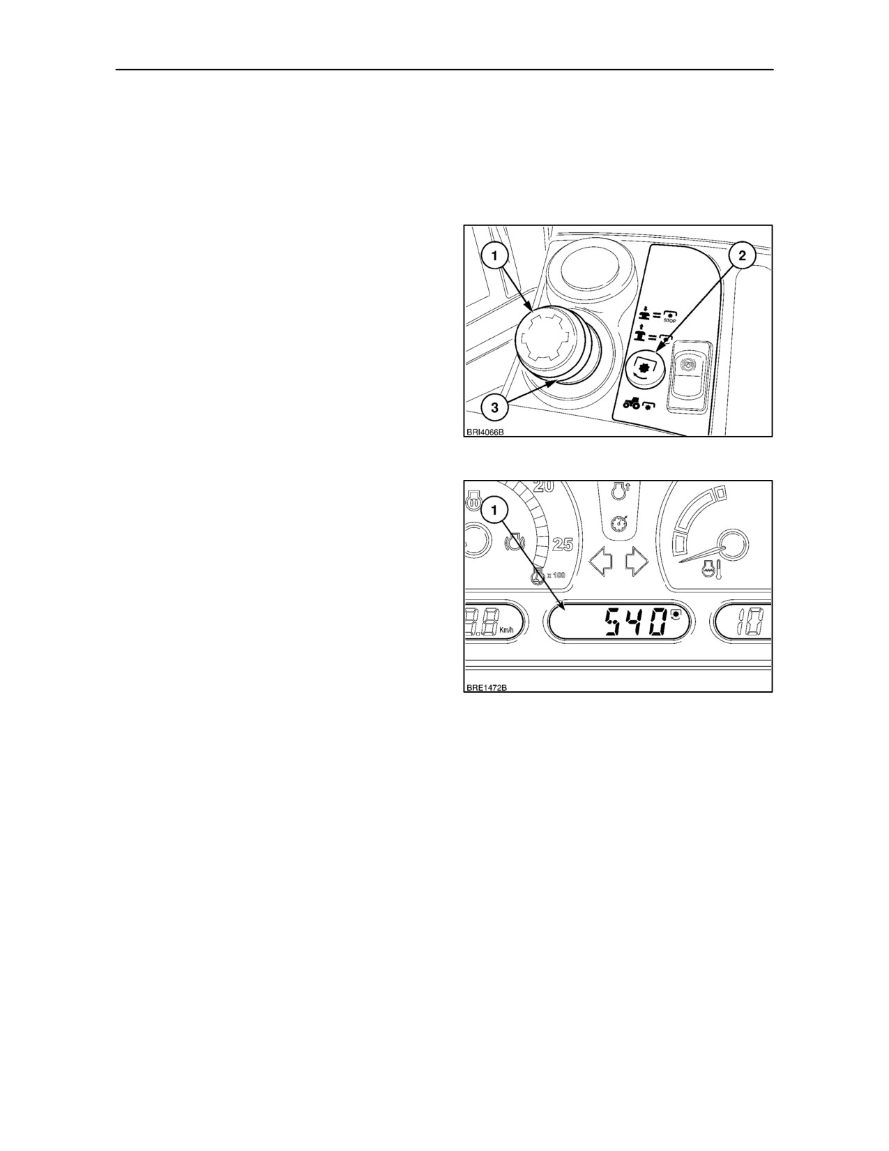
With the engine running at 1000 rev/min., press the
knob (1) and lift the collar (3) and knob up to engage
the P.T.O. The knob will remain up while the P.T.O.
is engaged and the adjacent warning light (2) will be
illuminated.
IMPORTANT: To avoid shock loads to the P.T.O.,
reduce engine speed to approximately 1000 rev/min
when engaging the P.T.O.
21
Open the throttle to obtain the required engine/P.T.O.
speeds. The P.T.O. speed can be displayed in the
central LCD on the instrument panel (1).
NOTE: The light (2) Figure 21, will be illuminated
when the P.T.O. is engaged. If overspeeding of the
P.T.O. occurs (P.T.O. speed exceeds 630 rev/min)
the light will flash for 5 seconds, then remain steady.
When the 1000 rev/min/shaft is in use, the light may
also flash (but may be ignored) as P.T.O. shaft speed
passes through the 630 rev/min range. The light will
flash again at 1170 P.T.O. rev/min to indicate that
overspeeding has occurred in the 1000 rev/min
P.T.O. range.
22
Press the knob firmly down to disengage the P.T.O.
3--19
SECTION 3 -- FIELD OPERATION
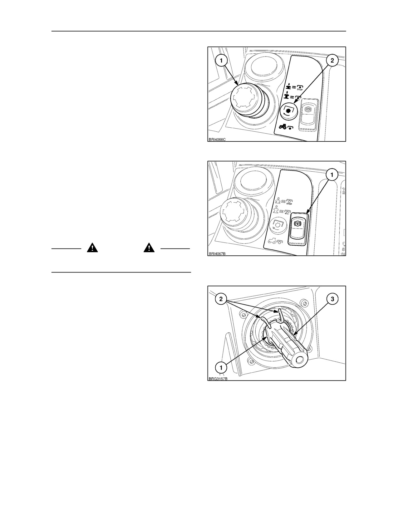
NOTE: If the engine is stopped, the P.T.O. will not
operate when the engine is restarted until the P.T.O.
knob (1) is reset. Return the control knob manually
to the ‘off’ position (by pressing the knob down) then
re-engage the P.T.O., as previously described.
23
IMPORTANT: An automatic P.T.O. brake is installed
to stop shaft rotation quickly when the P.T.O. is
disengaged. To avoid overstressing the P.T.O.
brake, slow down the implement by reducing engine
speed before disengaging the P.T.O. This is
particularly important with implements having a high
inertia. Such implements should, ideally, be
equipped with an overrun clutch. To avoid damage to
the brake when operating high inertia implements,
hold down the switch (1), to disengage the brake and
allow the implement to come to rest naturally.
DANGER
To avoid inadvertent movement of the implement,
24
disengage the P.T.O. after each use.
CHANGING THE P.T.O. SHAFT SPEED
IMPORTANT: Before changing the speed of the
output shaft, switch off the P.T.O., stop the engine
and apply the handbrake.
Using a suitable tool, compress the lugs on the circlip
and remove it from the P.T.O. housing. Carefully
withdraw the output shaft.
NOTE: To aid removal, rotate the circlip until the lugs
(2), align with the flat on the P.T.O. shaft (1).
Thoroughly clean the P.T.O. shaft before re--inserting
25
it into the housing. Ensure the number of splines on
the shaft (3), correspond to those on the implement
drive shaft.
Replace the circlip ensuring it engages fully with the
groove in the P.T.O. housing.
IMPORTANT: After re--fitting, rotate the circlip 180°
in the housing so the lugs are opposite the flat on the
output shaft.
3--20
SECTION 3 -- FIELD OPERATION
TWO--SPEED, SHIFTABLE P.T.O.
(where fitted)
A 6--spline P.T.O. output shaft of 1.375 in. (34.9 mm)
diameter is supplied, designed to operate at 540
rev/min.
Dependent upon tractor specification, an alternative
21--spline shaft of 1.375 in. (34.9 mm) diameter,
designed to operate at 1000 rev/min., may also be
supplied with the tractor or is available from your
dealer.
Operating
Before engaging the P.T.O., select a P.T.O. ratio, as
follows:
With 6--spline shaft installed
• WiththetractorstationaryandtheP.T.O.control
knob in the disengaged position, select the
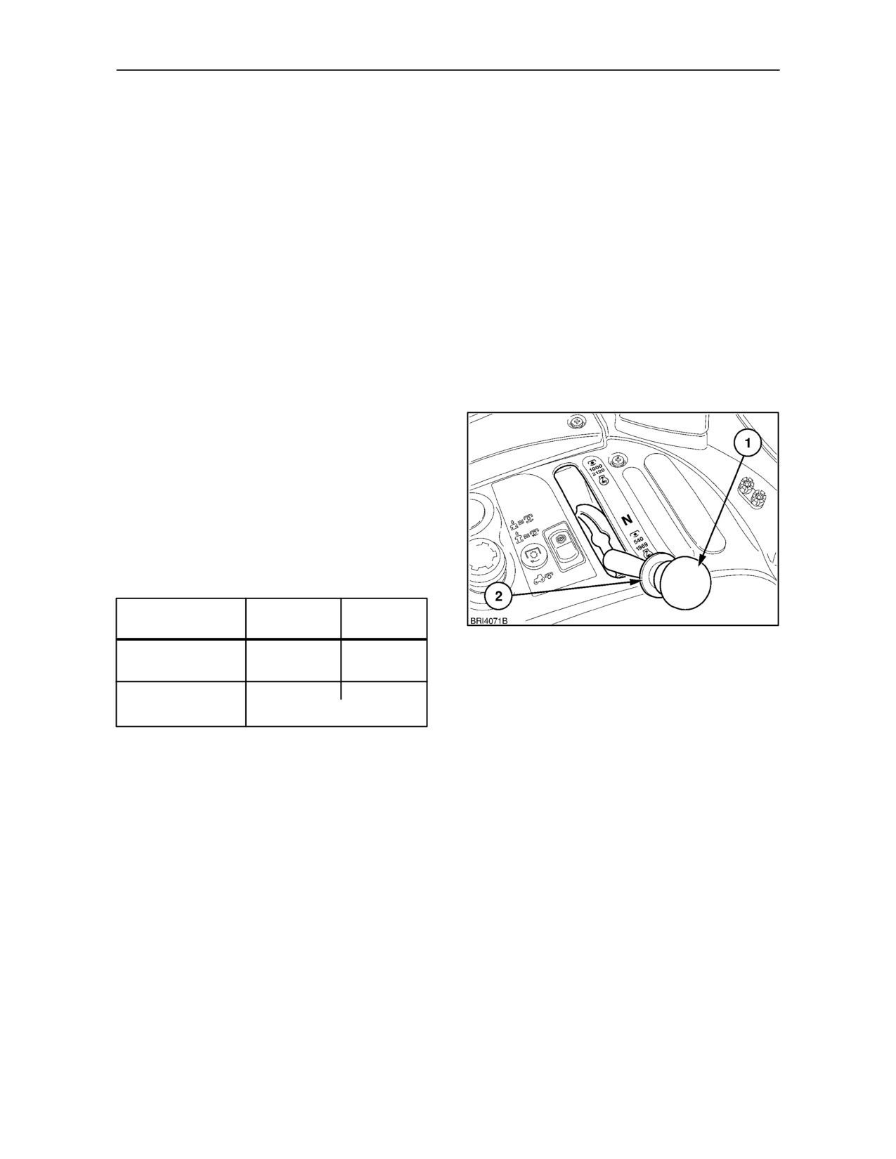
required speed by means of the range lever (1).
Lift the spring-loaded collar (2) beneath the knob
and move the lever to engage the power or
economy range.
Engine and P.T.O. shaft speeds are as follows:
Range Lever
Engine Speed
P.T.O. Speed
Position
(rev/min)
(rev/min)
26
Fully rearward
1970
540
(6--spline shaft)
Fully forward
1145
540
(6--spline shaft)
(light operations only)
IMPORTANT: The P.T.O. range lever cannot be
moved until the spring-loaded collar beneath the
knob is lifted. This feature is incorporated to prevent
inadvertent selection of the economy range which
could result in overspeeding of a P.T.O. driven
implement.
3--21
SECTION 3 -- FIELD OPERATION
With 21--spline shaft installed
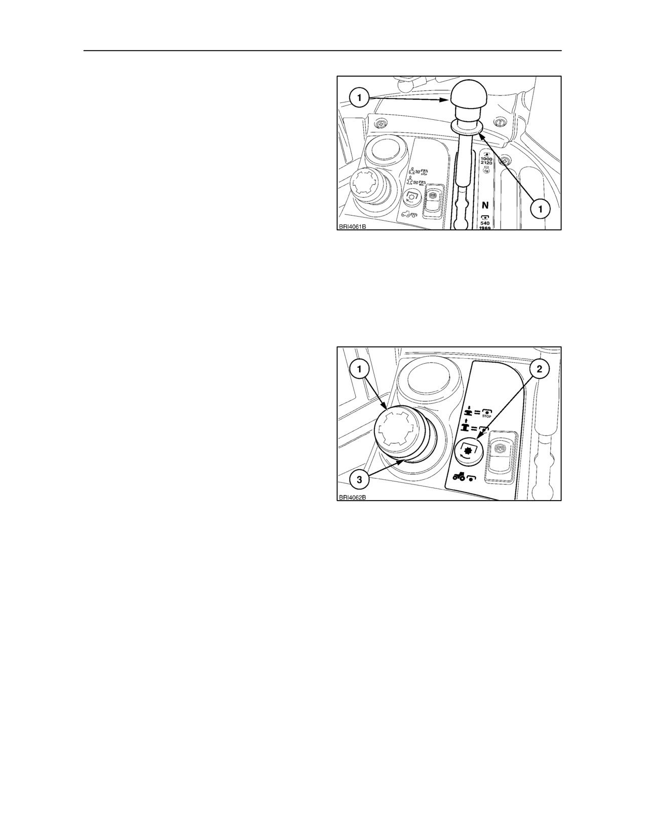
• WiththetractorstationaryandtheP.T.O.control
knob in the disengaged position, lift the
spring-loaded collar (2), beneath the knob, and
move the lever (1) fully to the right. This will
provide a P.T.O. speed of 1000 rev/min at 2120
engine rev/min.
NOTE: The P.T.O. range lever should always be in the
2120 position when the 21--spline shaft is installed. If
you only ever operate with a 21--spline shaft, leave the
range lever in this position.
27
With 6-- or 21--spline shaft installed
IMPORTANT: To avoid shock loads to the P.T.O.,
reduce engine speed to approximately 1000 rev/min
when engaging the P.T.O., then increase engine
speed by means of the throttle to obtain the required
P.T.O. speed.
With the engine running at 1000 rev/min. or less,
press the knob (1) and lift the collar (3) and knob up
to engage the P.T.O. The knob will remain up while
the P.T.O. is engaged and the adjacent warning light
(2) will be illuminated.
To disengage the P.T.O., press the P.T.O. control
knob (1), down.
NOTE: If the engine is stopped, the P.T.O. will not
operate when the engine is restarted until the P.T.O.
knob is reset. Return the control knob manually to the
‘off’ position
(by pressing the knob down) then
re-engage the P.T.O., as previously described.
28
IMPORTANT: Although the P.T.O. may be engaged
or disengaged with the tractor moving or stationary,
do not attempt to change from one P.T.O. speed
range to another unless the tractor is stationary and
the P.T.O. disengaged -- control knob (1), fully down.
3--22
SECTION 3 -- FIELD OPERATION
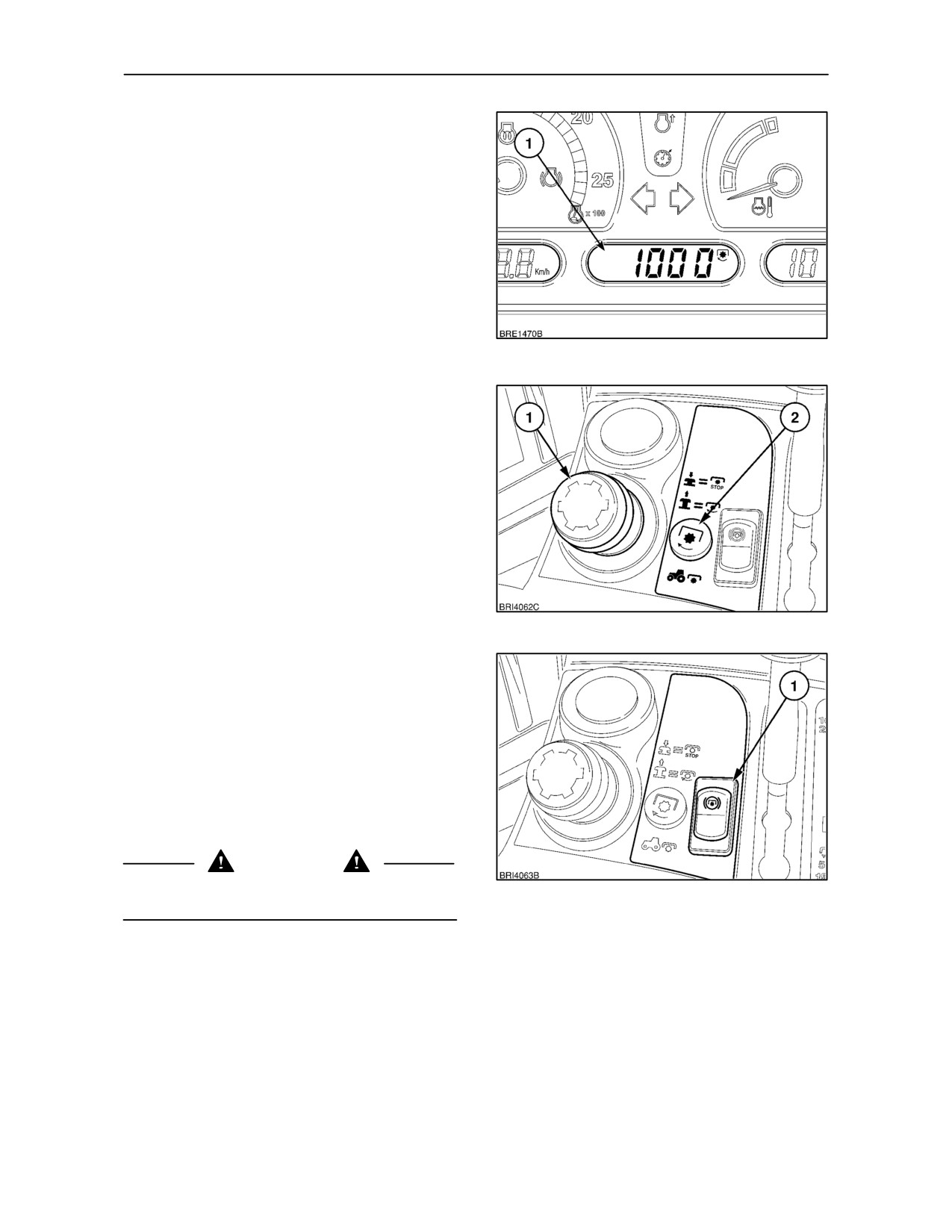
NOTE: The P.T.O. shaft speed (1) may be displayed
in the central LCD if required.
29
NOTE: If overspeeding of the P.T.O. occurs (i.e.
P.T.O. speed exceeds 630 rev/min) the light (2) will
flash for 5 seconds, then remain steady. When the
1000 rev/min shaft is in use, the light may also flash
(but may be ignored) as P.T.O. shaft speed passes
through the 630 rev/min range. The light will flash
again at
1170
P.T.O. rev/min to indicate that
overspeeding has occurred in the 1000 rev/min
P.T.O. range.
30
IMPORTANT: An automatic P.T.O. brake is installed
to stop shaft rotation quickly when the P.T.O. is
disengaged. To avoid overstressing the P.T.O.
brake, slow down the implement by reducing engine
speed before disengaging the P.T.O. This is
particularly important with implements having a high
inertia. Such implements should, ideally, be fitted
with an overrun clutch. To avoid damage to the brake
when operating high inertia implements, hold down
the switch (1), to disengage the brake and allow the
implement to come to rest naturally.
DANGER
To avoid inadvertent movement of the implement,
31
disengage the P.T.O. after each use.
3--23
SECTION 3 -- FIELD OPERATION
THREE--SPEED, SHIFTABLE P.T.O.
(where fitted)
A 6--spline P.T.O. output shaft of 1.375 in. (34.9 mm)
diameter is supplied, designed to operate at 540
rev/min.
Dependent upon tractor specification, an alternative
21--spline shaft of 1.375 in. (34.9 mm) diameter,
designed to operate at 1000 rev/min., may also be
supplied with the tractor or is available from your
dealer.
Operating
Before engaging the P.T.O., select a P.T.O. ratio, as
32
follows:
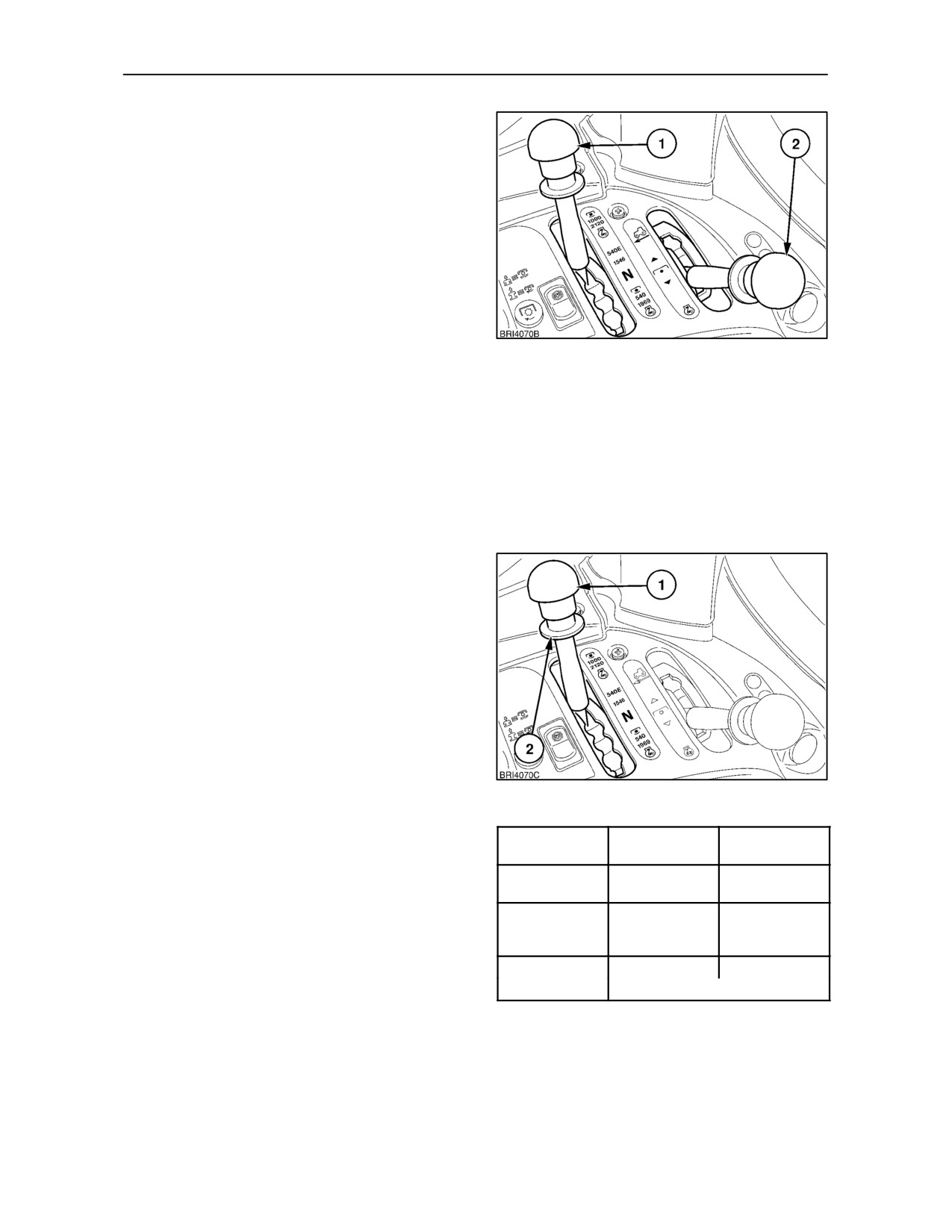
IMPORTANT: If your tractor has the optional ground
drive P.T.O., an additional lever (2) is provided. To
prevent damage to the P.T.O. driveline, ensure that
this lever is moved fully to the left, as shown, before
operating the engine-driven P.T.O.
(The forward
position is used to engage ground drive P.T.O.).
With 6--spline shaft installed
• WiththetractorstationaryandtheP.T.O.control
knob in the disengaged position, select the
required speed by means of the range lever (1).
Lift the spring-loaded collar (2) beneath the knob
and move the lever fully to the right to engage
1000 speed, to the intermediate position for 540
Economy, and fully to the left for standard 540
speed.
IMPORTANT: The P.T.O. range lever cannot be
moved until the spring-loaded collar beneath the
knob is lifted. This feature is incorporated to prevent
inadvertent selection of the economy range which
could result in overspeeding of a P.T.O. driven
33
implement.
Operating
Range Lever
Engine Speed
P.T.O. Speed
Position
(rev/min)
(rev/min)
NOTE: The 3-speed P.T.O. range lever has a neutral
Fully rearward
1970
540
position, denoted by the letter ‘N’. See Figure 33.
(6--spline shaft)
Intermediate
1546
540
Engine and P.T.O. shaft speeds are as follows:
position
(6--spline shaft)
Fully forward
1145
540
(6--spli
ne shaft)
(light operations only)
3--24
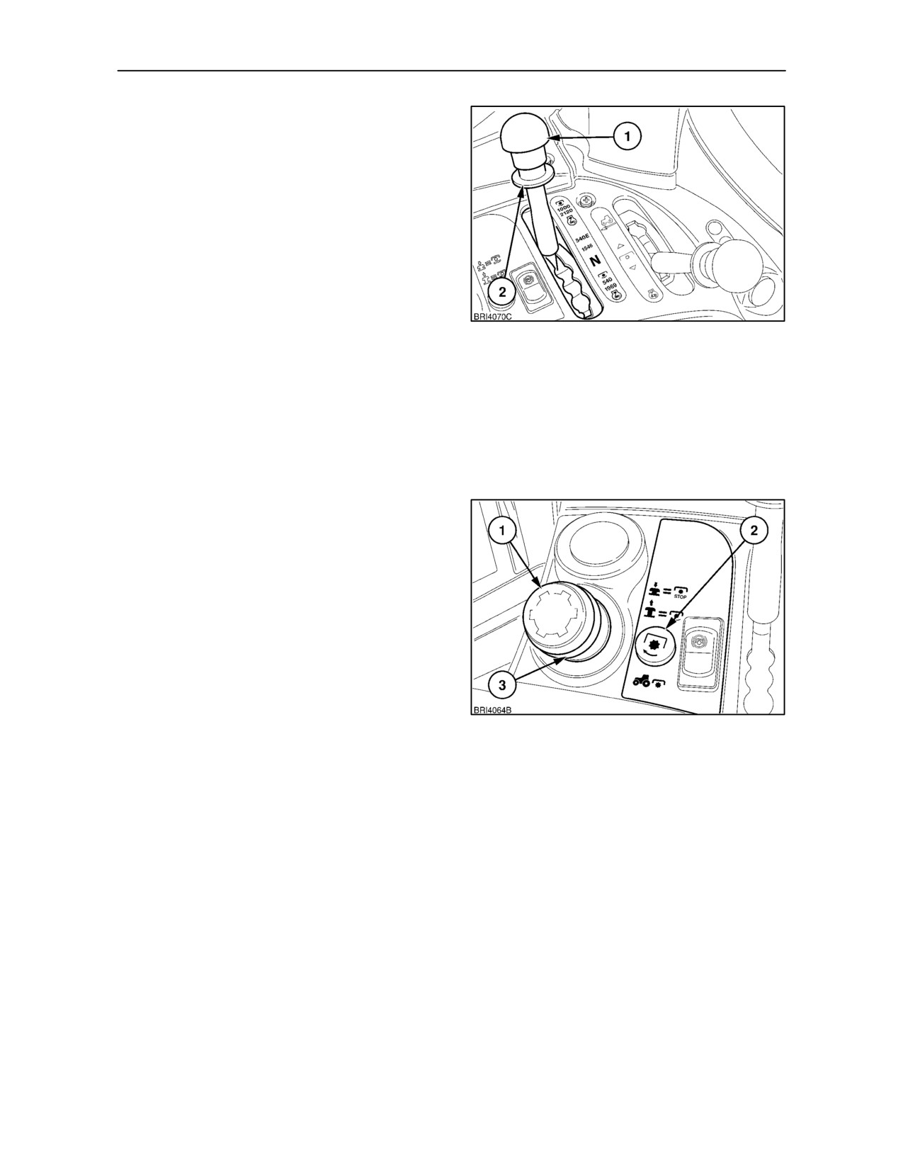
SECTION 3 -- FIELD OPERATION
With 21--spline shaft installed:
• WiththetractorstationaryandtheP.T.O.control
knob in the disengaged position, select the
required speed by means of the range lever (1).
Lift the spring-loaded collar (2) beneath the knob
and move the lever fully to the right. This will
provide a P.T.O. speed of 1000 rev/min at 2120
engine rev/min.
NOTE: The P.T.O. range lever should always be in this
position when the 21--spline shaft is installed.
34
With 6-- or 21--spline shaft installed
IMPORTANT: To avoid shock loads to the P.T.O.,
reduce engine speed to approximately 1000 rev/min
when engaging the P.T.O., then increase engine
speed by means of the throttle to obtain the required
P.T.O. speed.
With the engine running at 1000 rev/min. or less,
press the knob (1) and lift the collar (3) and knob up
to engage the P.T.O. The knob will remain up while
the P.T.O. is engaged and the adjacent warning light
(2) will be illuminated.
To disengage the P.T.O., press the P.T.O. control
knob (1) down.
NOTE: If the engine is stopped, the P.T.O. will not
operate when the engine is restarted until the P.T.O.
knob is reset. Return the control knob manually to the
‘off’ position
(by pressing the knob down) then
re-engage the P.T.O., as previously described.
35
IMPORTANT: Although the P.T.O. may be engaged
or disengaged with the tractor moving or stationary,
do not attempt to change from one P.T.O. speed
range to another unless the tractor is stationary and
the P.T.O. disengaged -- control knob (1), fully down.
3--25
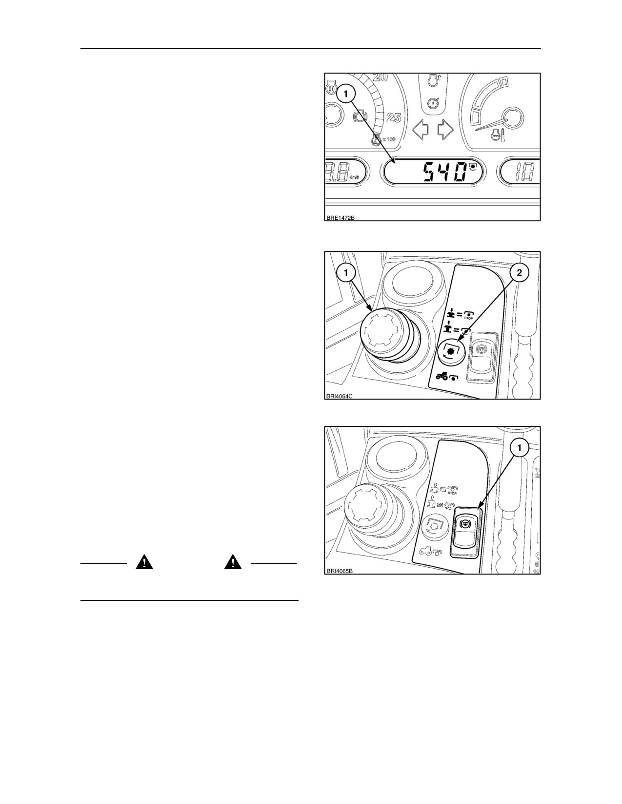
SECTION 3 -- FIELD OPERATION
NOTE: The P.T.O. shaft speed (1) may be displayed
in the central LCD if required.
36
NOTE: If overspeeding of the P.T.O. occurs (i.e.
P.T.O. speed exceeds 630 rev/min) the light (2), will
flash for 5 seconds, then remain steady. When the
1000 rev/min shaft is in use, the light may also flash
(but may be ignored) as P.T.O. shaft speed passes
through the 630 rev/min range. The light will flash
again at
1170
P.T.O. rev/min to indicate that
overspeeding has occurred in the 1000 rev/min
P.T.O. range.
37
IMPORTANT: An automatic P.T.O. brake is installed
to stop shaft rotation quickly when the P.T.O. is
disengaged. To avoid overstressing the P.T.O.
brake, slow down the implement by reducing engine
speed before disengaging the P.T.O. This is
particularly important with implements having a high
inertia. Such implements should, ideally, be fitted
with an overrun clutch. To avoid damage to the brake
when operating high inertia implements, hold down
the switch (1), to disengage the brake and allow the
implement to come to rest naturally.
DANGER
To avoid inadvertent movement of the implement,
38
disengage the P.T.O. after each use.
3--26
SECTION 3 -- FIELD OPERATION
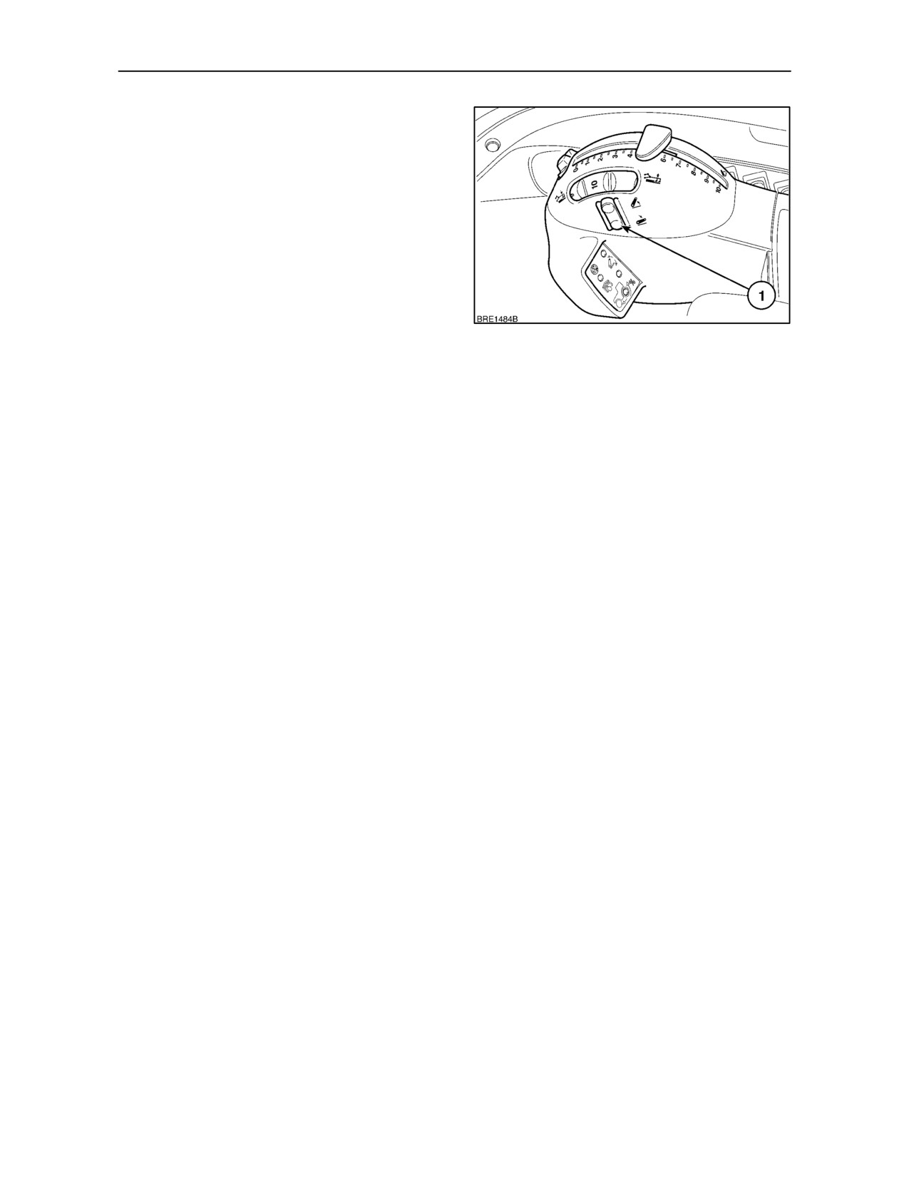
AUTO P.T.O. FUNCTION (where fitted)
With Electronic Draft Control
The Auto P.T.O. function provides automatic
engagement or disengagement of the rear P.T.O.
drive when using the EDC raise/lower switch (1).
Operating the switch to raise the implement will
automatically disengage P.T.O. drive. Lowering the
implement with the switch will re--engage P.T.O.
drive.
The height at which the P.T.O. is engaged or
disengaged can be set using the following method.
39
IMPORTANT: The tractor must be stationary and the
P.T.O. switched off before attempting this procedure.
• With the engine running and the P.T.O. switched
off, operate the lift control to capture the hitch.
• Depress and hold the P.T.O. switch for
2
seconds. The central display will show
’u’
followed by two figures, for example, ’u38’. The
figure 38 representing the current height of the
hitch.
• Raise the hitch to point at which the P.T.O. is to
disengage. Depress the P.T.O. switch once, the
central display will show ’d xx’ (where ’xx’ is the
current height of the hitch).
• Lower the hitch to the point where the P.T.O. is
to re--engage and depress the P.T.O. switch
again. The central display will show ’End’ for two
seconds and then return to the option selected
prior to entering set--up mode.
Providing the tractor is stationary and the P.T.O. is
disengaged, this procedure can be carried out at any
time. The new settings will remain in the memory until
re--programmed.
3--27