New Holland T6010, T6020, T6030, T6050, T6070 Delta and Plus Tractors. Operator's Manual - page 3
SECTION 2 -- CONTROLS, INSTRUMENTS AND OPERATION
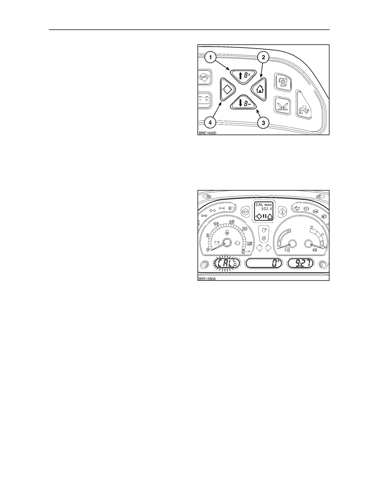
Manual Calibration with Enhanced Keypad
(where fitted)
• With the key--start in the ON position, depress
and hold the Menu/Enter button
(2) for
3
seconds. The DMD will read SETUP_MENU,
this will change to CAL after 2 seconds. Depress
the Enter key and CAL manual will appear.
• Depress the Menu/Enter key again to change the
DMD display to CAL_Man_000.0. (The figure
000.0 may differ if a calibration number has
previously been entered). CAL will flash in the
speed display. Using the Digit Select key (↓)
98
move the cursor to the first digit to be set, enter
the number using the Digit Value key (↑). CAL
will appear in the speed display and start to flash.
Repeat the procedure to set the remaining
calibration figures that correspond to the size of
rear tyre fitted to your tractor.
IMPORTANT: When entering new tyre rolling
circumference figures, use metric values
(centimetres) with Km/h speedometer reading and
Imperial values (inches) with MPH reading, see table
on page 2--55.
• Depress the Exit/Cancel key twice to store the
setting and return to the main menu screen,
depress again to exit set up and return to the
original display.
99
2--54
SECTION 2 -- CONTROLS, INSTRUMENTS AND OPERATION
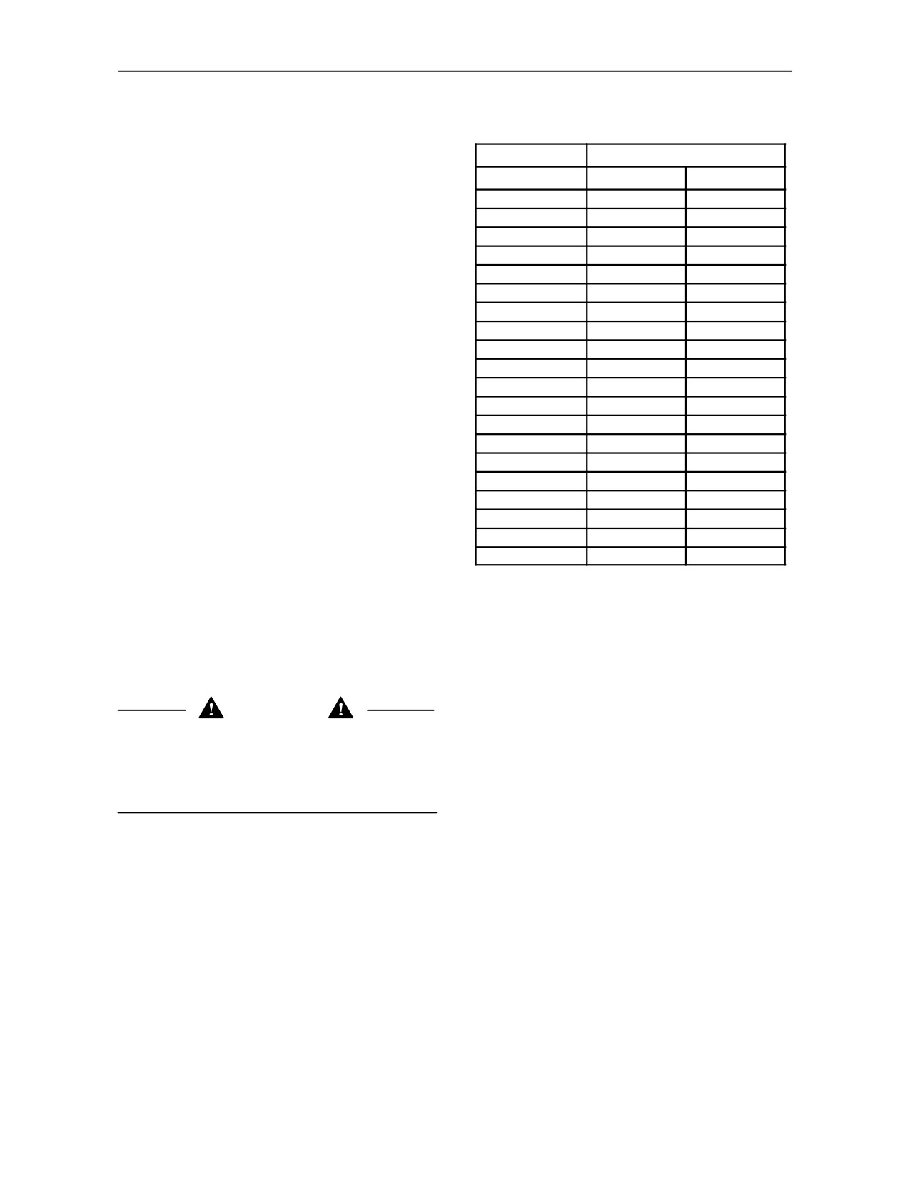
Ground Speed Calibration Numbers
Rear Tyre Rolling Circumferences
The rolling circumference for any given tyre size will
Tyre Size
Tyre Rolling Circumference
vary depending on tyre manufacturer. The figures
Centimetres
Inches
shown in the table are an average based on rolling
circumference data supplied by several
18.4R --
30
461.2
181.6
manufacturers. To obtain an accurate figure for your
12.4 --
32
406.9
160.2
rear tyres, consult your authorised dealer or tyre
16.9R --
34
473.1
186.3
supplier.
18.4R --
34
494.7
194.8
13.6R --
38
465.6
183.3
If the size of tyre on your tractor is not listed, then the
16.9R --
38
503.4
198.2
road speed calibration may be carried out using one
of the following procedures.
18.4R --
38
525.6
206.9
20.8R --
38
549.3
216.3
Carry out the Auto calibration as previously
18.4R --
42
552.7
217.6
described or measure the rear tyre rolling
14.9R --
46
554.2
218.2
circumference.
480/70R --
34
474.5
186.8
520/70R --
34
490.6
193.1
1. To measure the rolling circumference of the rear
480/70R --
38
506.5
199.4
tyre, park the tractor on a level surface and make
540/65R --
38
501.5
197.4
a vertical chalk mark on the sidewall where the
520/70R --
38
525.6
206.9
tyre tread contacts the ground. Make a second
chalk mark on the ground aligning with the mark
600/65R --
38
523.7
206.2
on the tyre.
650/60R --
38
510.8
201.1
650/65R --
38
544.5
214.4
2. Slowly drive the tractor forward until the rear
580/70R --
38
549.7
216.4
wheel has made one revolution and the chalk
320/90R --
50
560.3
220.6
mark on the sidewall is again in contact with the
ground. Mark the ground again and measure the
distance between the two chalk marks.
IMPORTANT: If your tractor is equipped with the
optional slip control feature, then the ground speed
displayed is a true speed as sensed by a radar unit,
calibration is therefore not required.
WARNING
The radar ground speed sensor emits a low intensity
microwave signal which will not cause any ill effects
in normal use. Although the signal intensity is low, do
not look directly into the face of the sensor while in
operation so as to avoid eye damage.
2--55
SECTION 2 -- CONTROLS, INSTRUMENTS AND OPERATION
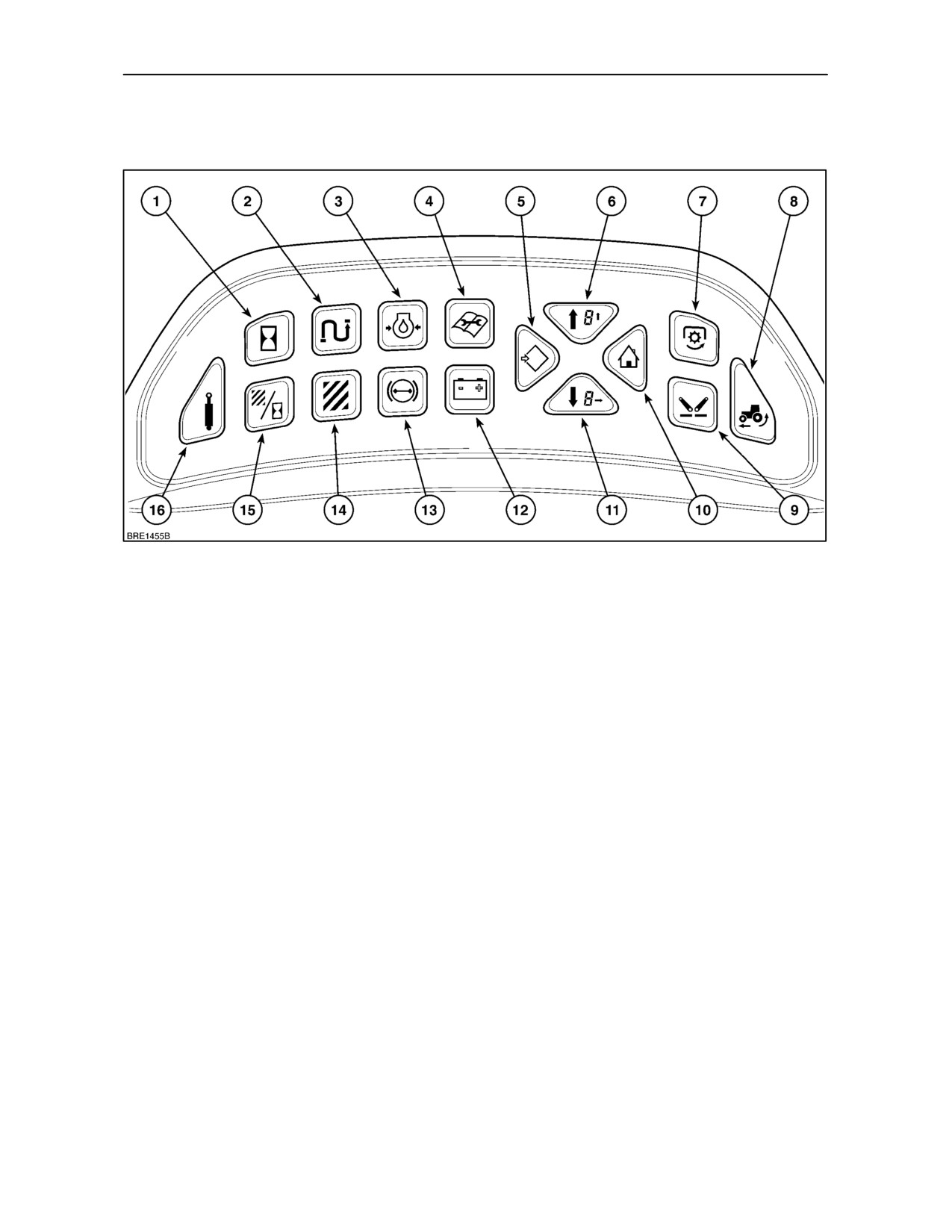
ENHANCED KEYPAD and
PERFORMANCE MONITOR (where fitted)
100
The enhanced keypad consists of 16 buttons or
3. Engine Oil Pressure (D). This key will display the
’keys’ that select, control or programme various
engine oil pressure bargraph (where fitted).
functions and displays in the central and dot matrix
screens. Keys 5, 6, 10 and 11 are used to set--up and
4. Programmed Maintenance Reminder (D). The
programme many of the enhanced keypad functions.
maintenance schedule key provides two levels of
reminder identified as ’Heavy’ and Light.
Unless otherwise described, depress the keys once
5. Menu Enter (D). Depress to select set--up and
to obtain the appropriate display. A symbol will
programming modes.
appear in the display to confirm the function
selected.
6. Menu Scroll Up or Digit Value (D). Depress this
key repeatedly to scroll upwards through the
Legend:
(D) = Dot Matrix Disply
menu or change the value of a number.
(C) = Centre Digital Display
7. P.T.O. Speed (C). Depress once to display rear
1. Hourmeter (D). Touch the key to view total
Power Take Off speed, press again and hold for
number of hours that the tractor has operated.
3 seconds to show front P.T.O. speed (where
The hours recorded should be used as a guide to
fitted).
the service intervals for the tractor.
8. Rear Wheel Slip (C). The level of rear wheel slip
2. Odometer (D). The odometer provides a visual
will appear as a one or two digit percentage (%)
record of the distance travelled in kilometres or
figure (with radar option only).
miles depending on the ground speed unit
selected. Two displays are available, ’1’ and ’2’.
2--56
SECTION 2 -- CONTROLS, INSTRUMENTS AND OPERATION
ENHANCED KEYPAD and
PERFORMANCE MONITOR (continued)
101
9. Linkage Height Position (C). Depress once to
14. Area Accumulator (D). The total area worked will
display the rear linkage height, press again and
be displayed in hectares or acres depending on
hold for 3 seconds to show front linkage height
the ground speed unit selected.
(where fitted). The display will show a figure
between ’0’ (fully lowered) and ’100’ (maximum
15. Area Per Hour Forecaster (D). Touch this key
raised position).
and the area/hour symbol will display together
with a forecast of the area that will be worked in
10. Exit/Cancel (D). Use this key to Exit or cancel
one hour if the current rate of work is continued.
set--up and programming modes.
NOTE: If the radar option is not installed, area per
11. Menu Scroll Down or Digit Select (D). Depress
hour calculations are based on axle speed and are
this key to scroll downwards through the menu or
subject to inaccuracies caused by any wheel slip that
select an alternative digit in the Dot Matrix
may occur.
Display.
16. Remote Valve Operation (D). The display will
12. Battery Voltage (D). With the engine running,
show the flow rate through each valve as a
touch the key to display the battery symbol
percentage
(%), the direction of cylinder
together with a digital display of the battery
movement (extend or retract) and the number of
voltage.
the valve selected.
(See Electronic Remote
Control Valves in Section 3).
13. Trailer Brake Air Pressure
(D). Depress to
display the trailer brake air pressure bargraph.
2--57
SECTION 2 -- CONTROLS, INSTRUMENTS AND OPERATION
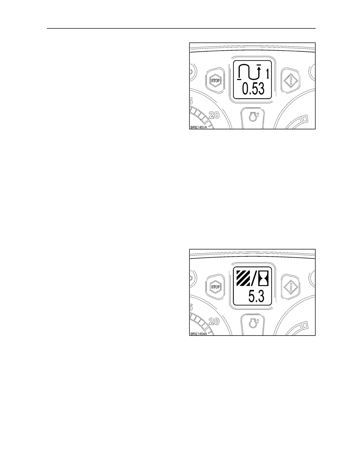
Odometer (Distance Record)
The odometer provides a visual record of the
distance travelled in kilometres or miles depending
on the ground speed unit selected.
Two displays are available, ’1’ and ’2’. ’1’ may be
used for individual journey distances and
’2’ to
provide a total for all journeys travelled. Both ’1’ and
’2’ may be reset to zero.
Touch the key once to select reading ’1’, touch again
to select reading ’2’. Keeping the key depressed for
more than
3 seconds will re--set the selected
102
odometer to zero.
The journey distance in the display (3) will appear in
steps of:
0 to 19.999 Km/Miles
0.001 Km/Miles
20 to 199.99 Km/Miles
0.01 Km/Miles
200 to 1999.9 Km/Miles
0.1 Km/Miles
2000 to 19999 Km/Miles
1.0 Km/Miles
NOTE: If the radar option is not installed, distance
calculations are based on axle rotation and are
subject to inaccuracies caused by any wheel slip that
may occur.
Area per Hour Forecaster
Touch the AREA/HOUR key (1). The ‘AREA/HOUR’
symbol will display, together with a forecast (2) of the
area that will be worked in one hour if the current rate
of work is continued.
The area per hour will appear in steps of 0.01
Ha/Acre.
NOTE: If the radar option is not installed, area per
hour calculations are based on axle speed and are
subject to inaccuracies caused by any wheel slip that
may occur.
103
2--58
SECTION 2 -- CONTROLS, INSTRUMENTS AND OPERATION
Area Accumulator
NOTE: Before activating the area accumulator
function ensure the correct implement width has
been entered into the TPM memory.
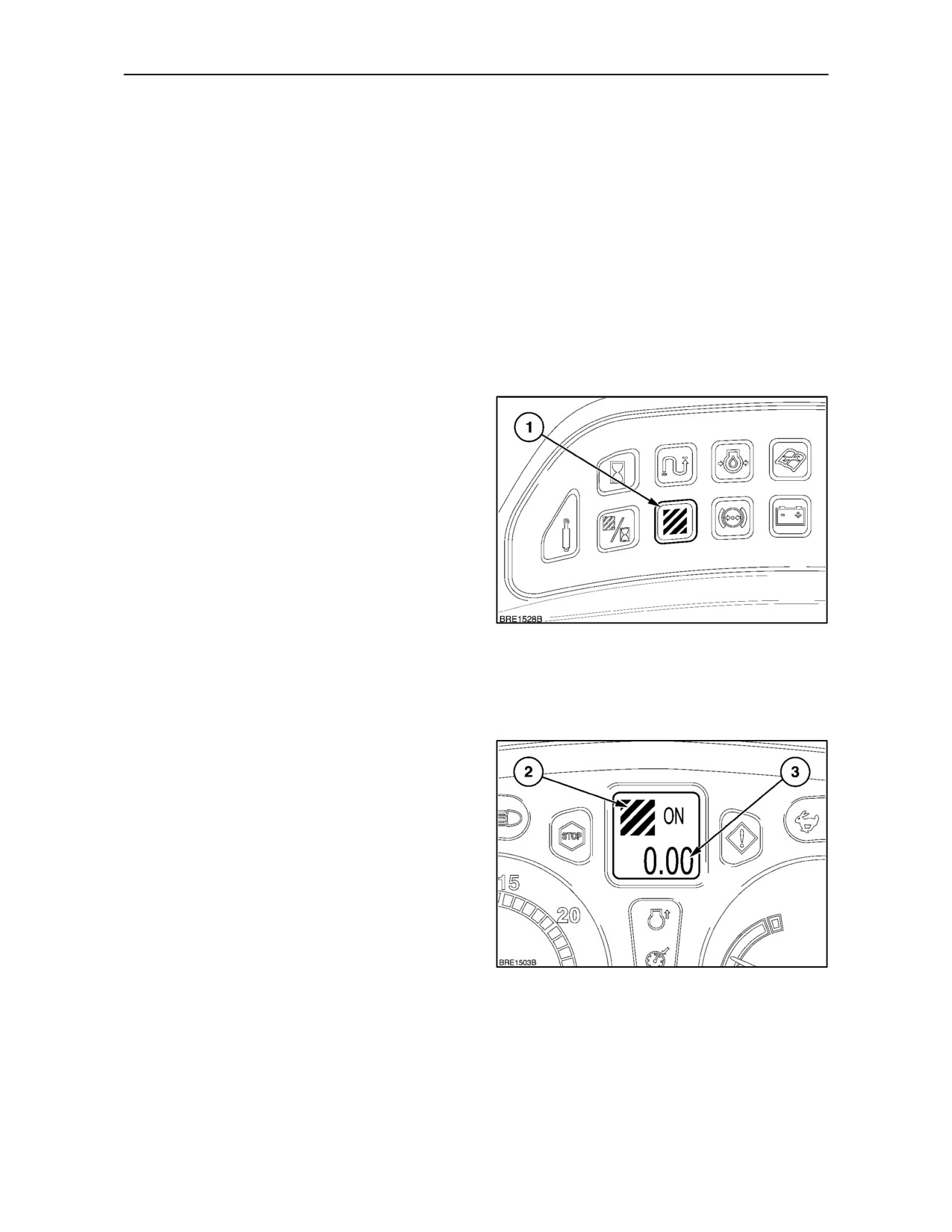
The accumulated area (total area worked) can be
displayed by depressing the AREA key
(1).
Depending on the unit set in the tractor speed display
(K/mh or MPH) the reading will be in hectares or
acres.
Depress the area accumulator key repeatedly to
toggle through the three displays in the dot matrix
screen:
1. OFF. The area accumulator is off.
2. ON. Area accumulator on. Area will be
accumulated as the tractor moves irrespective of
the position of the implement.
3. A.
Area accumulation will start recording
when the tractor moves and the implement is
lowered. It will stop accumulating when the
implement is raised.
The area accumulator symbol (2) will appear in the
display along with the area figure.
104
With trailed equipment, area accumulation may be
temporarily interrupted, for example, at the
headland, by means of a switch connected into the
implement status socket
(where fitted). See
‘Electrical Power Panel’ on page 2--21.
The area measurement in the display (3) will appear
in steps of:
0 to 199.99 Ha/acre
0.01 Ha/acre
200 to 1999.9 Ha/acre
0.1 Ha/acre
2000 to 19999 Ha/acre
1.0 Ha/acre
Area accumulation can be reset to zero at any time
by selecting OFF and holding down the AREA key (1)
Figure 104, until the display returns to zero.
NOTE: If the radar option is not installed, area per
hour calculations are based on axle speed and are
105
subject to inaccuracies caused by any wheel slip that
may occur.
2--59
SECTION 2 -- CONTROLS, INSTRUMENTS AND OPERATION
PROGRAMMING THE DISPLAYS
WARNING
The radar ground speed sensor, located in front of
the right-hand footsteps, emits a low intensity
microwave signal which is completely safe in normal
use. Although the signal intensity is low, do not look
directly into the face of the sensor while in operation
so as to avoid eye damage.
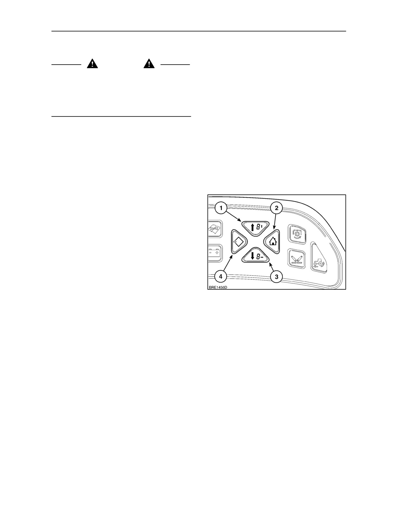
Programming Keys
Four keys are used to select, change or memorise
the various functions related to the performance
monitor and enhanced keypad. All programme
information will appear in the Dot Matrix Display
(DMD) along with the relevant symbol for the function
selected.
1.
Menu Up/Digit Value Key. Use this key to scroll
upwards through the function menu or to
increase the value of a selected digit during a
calibration procedure. Values will increase by
one each time the key is depressed.
2.
Exit/Cancel Key. Depress this key to exit the
calibration mode. The key may be used at any
time during a set--up procedure to cancel and exit
the calibration mode, however, information not
saved will be lost.
3.
Menu Down/Digit Select Key. In the calibration
mode depress this key to scroll downwards
through the menu or to select a digit for
106
re--calibration. Each time the key is depressed
the flashing cursor showing the current digit
selected will move one space to the right.
4.
Menu Enter Key. Depress this key for 3 seconds
to enter the programme mode, SETUP/MENU
will appear initially in the display. After 2 seconds
the display will change to read CAL. This will be
accompanied by the Menu Up/Down arrows and
the Menu Enter symbol.
When the appropriate function screen has been
selected, depress the Menu/Enter key again to
access the calibration mode.
2--60
SECTION 2 -- CONTROLS, INSTRUMENTS AND OPERATION
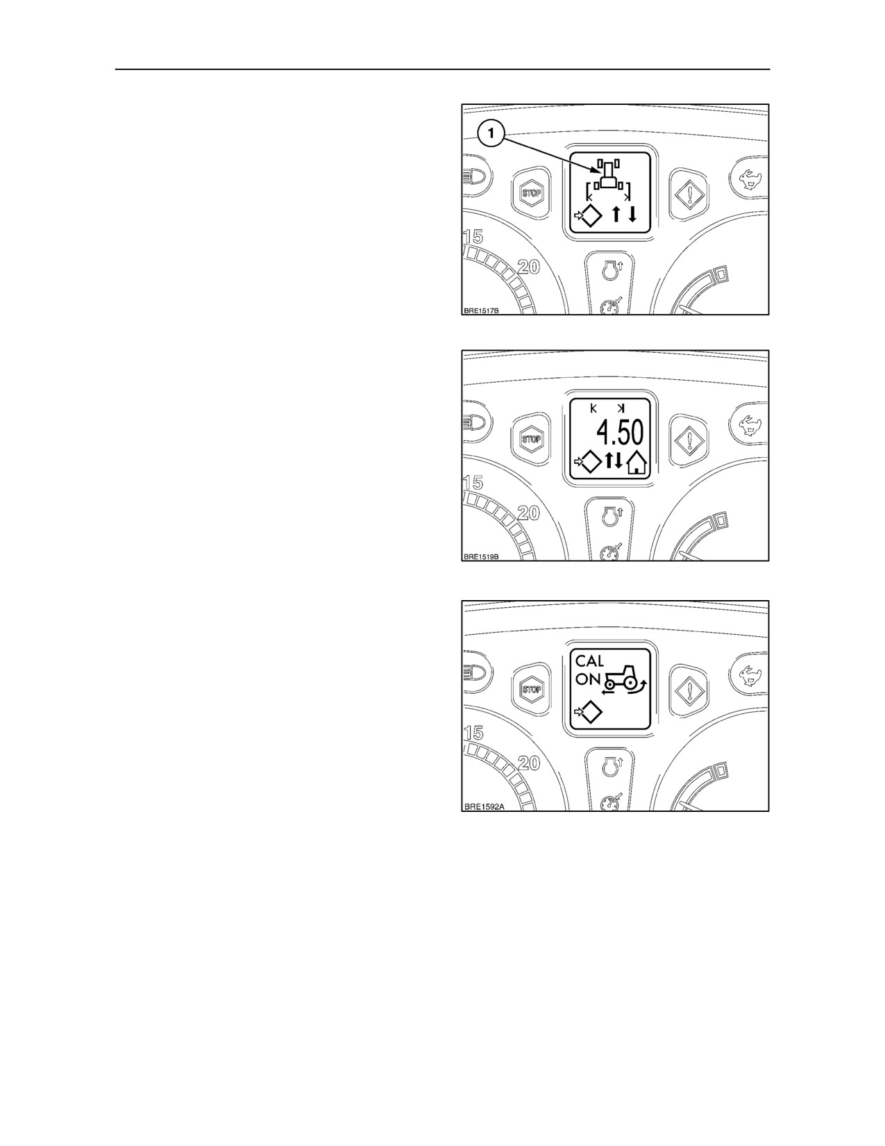
Setting the Implement Width
In order that the micro-processor may calculate the
cumulative area, the working width of the implement
must be entered into the memory. For example, to
enter an implement working width of 4.5 metres
(14.76 ft.) carry out the following procedure.
• With the key--start in the ON position, depress
and hold the Menu/Enter key for 3 seconds. The
DMD will read SETUP_MENU, this will change
to CAL after
2
seconds. Using the Menu
Up/Down keys, scroll through the menu until the
implement width symbol is displayed.
107
• Depress the Menu/Enter key again to select the
set--up screen, a flashing cursor will appear at
the first number to be set. Using the Digit Value
key enter ’0’ then move the cursor one space to
the right with the Digit Select key and enter ’4’.
Move the cursor to the right of the decimal point
and enter ’5’. The reading displayed should now
be 04.50 mtrs (14.76 ft.).
• Touch the Menu/Enter key to store the setting
and return to the main menu.
NOTE: The micro--processor cannot calculate the
area worked unless the correct implement width is
entered.
108
Calibrating for Wheel Slip
(where fitted)
Before setting the slip alarm point, a zero wheel slip
factor has to be determined. This calibration must be
carried out on a hard level surface where wheel slip
is unlikely to occur.
NOTE: The Electronic Draft Control auto slip
function (see EDC operation) will not operate unless
this procedure is carried out.
• With the tractor stationary and the engine
running, depress and hold the Menu/Enter key
for
3
seconds. The DMD will read
109
SETUP_MENU, this will change to CAL after 2
seconds. Using the Menu/Enter key, scroll
through the menu until the wheel slip symbol is
displayed.
• Drive the tractor at a constant speed above 5
Km/h (3.1 MPH). When a steady speed has been
reached, depress the Menu Enter key, CAL ON
will appear in the display. After a short distance
touch the Menu Enter key again, the display will
change to CAL OK.
• Touch the Menu/Enter key to store the setting
and return to the main menu.
2--61
SECTION 2 -- CONTROLS, INSTRUMENTS AND OPERATION
Setting the Slip Alarm Point
NOTE: If the optional radar unit is not installed, the
slip alarm function will be omitted from the display.
The slip alarm point may be set as a one or two digit
figure that, if exceeded, will cause an audible alarm
to sound. To set a wheelslip limit of 15%carry out the
following procedure.
• With the key--start in the ON position, depress
and hold the Menu/Enter key for 3 seconds. The
DMD will read SETUP_MENU, this will change
to CAL after
2
seconds. Using the Menu
110
Up/Down keys, scroll through the menu until the
wheel slip symbol (1) is displayed.
• Depress the Menu/Enter key again to select the
set--up screen, a flashing cursor will appear at
the first number to be set. Using the Digit Value
key enter ’1’, move the cursor to the right with the
Digit Select key and, with the Digit Value key,
enter ’5’. The slip alarm point is now set at 15%.
• Touch the Menu/Enter key to memorise the
setting and return to the main menu.
If wheelslipexceedsthepre--set limit,theslipsymbol
will appear in the DMD and the amber warning light
will illuminate on the instrument console.
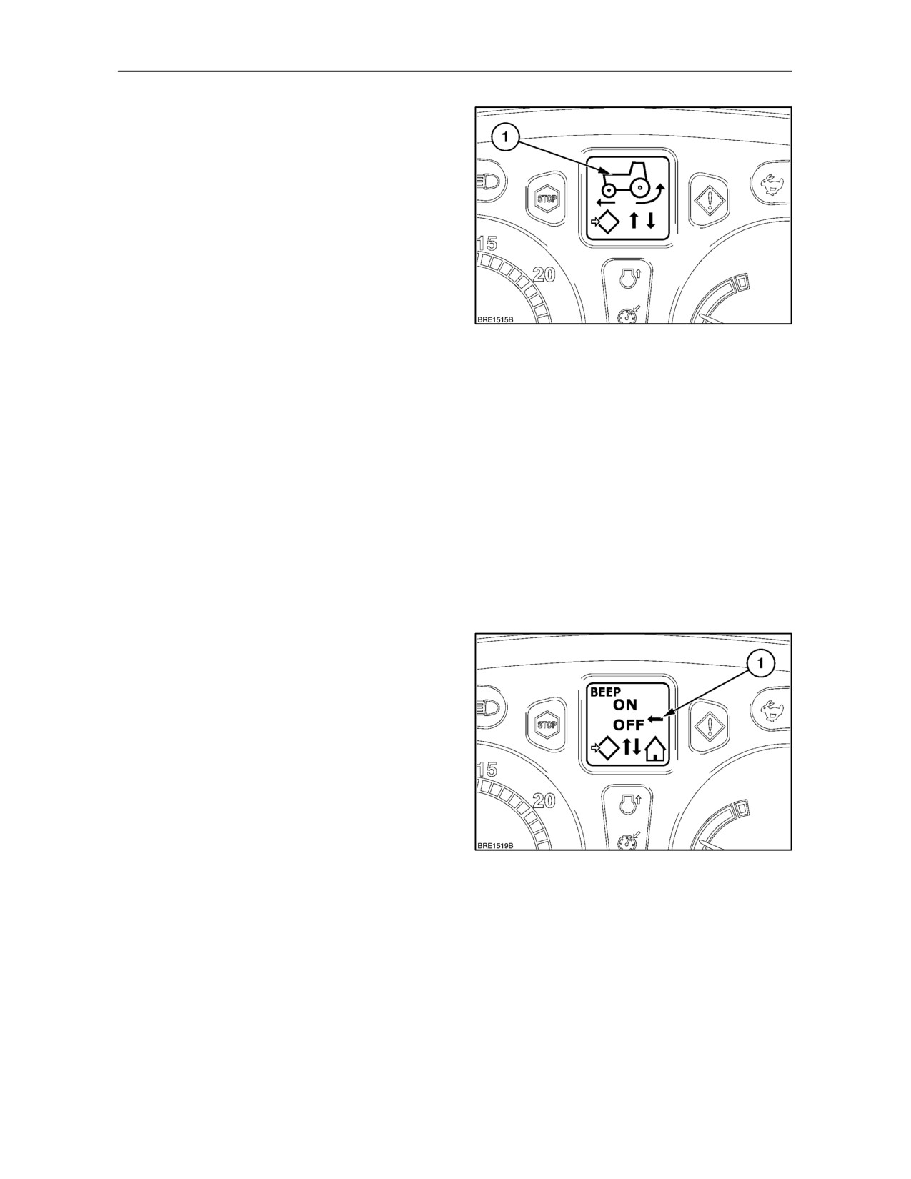
Audible Beep -- ON/OFF
Each time one of the keys is pressed, an audible
’beep’ sound will be heard. The beep can be switched
off if required.
• With the key--start in the ON position, depress
and hold the Menu/Enter key for 3 seconds. The
DMD will read SETUP_MENU, this will change
to CAL after
2
seconds. Using the Menu
Up/Down keys, scroll through the menu until
BEEP ON/OFF is displayed.
• Depress the Menu/Enter key again to select the
111
set--up screen. Using the Menu Up/Down keys,
align the arrow (1) with ON or OFF as required.
• Touch the Menu/Enter key to store the setting
and return to the main menu. Depress the
Exit/Cancel key to return to the original display.
2--62
SECTION 2 -- CONTROLS, INSTRUMENTS AND OPERATION
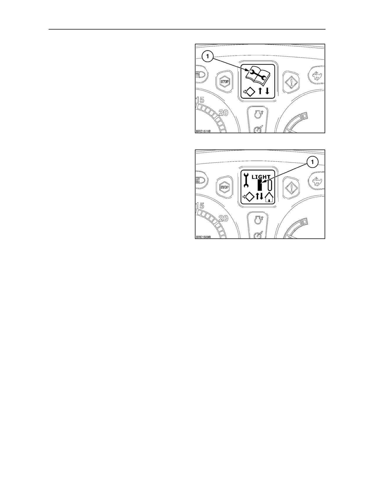
Programming the Service Reminder
The service reminder function allows the operator to
programme two service interval reminders using the
Enhanced Keypad. The following procedure is the
same for LIGHT and HEAVY service intervals.
• With the key--start in the ON position, depress
and hold the Menu/Enter key for 3 seconds. The
DMD will read SETUP_MENU, this will change
to CAL after
2
seconds. Using the Menu
Up/Down keys, scroll through the menu until the
service reminder symbol
(1) appears in the
display.
112
Setting a Light Service Reminder
• Depress the Menu/Enter key again to select the
Service Reminder sub--menu. Using the Menu
Up/Down keys display
’LIGHT’, touch the
Menu/Enter key and a flashing cursor (1) will
appear at the first number to be set. Using the
Digit Value key enter the first number to be set,
move the cursor one space to the right with the
Digit Select key and, with the Digit Value key,
enter the second digit, repeat for the third digit.
The display will now read LIGHT -- -- -- (where ------
will be the selected hours).
113
• Touch the Menu/Enter key to memorise the
setting and return to the main menu. Depress the
Exit/Cancel key to return to the original display.
The service reminder is now set for the selected
period.
Two hours before the service is due the Light Service
symbol and the hours remaining will appear in the
DMD at ’key--on’ and will remain displayed for 4
seconds after the engine is started.
2--63
SECTION 2 -- CONTROLS, INSTRUMENTS AND OPERATION
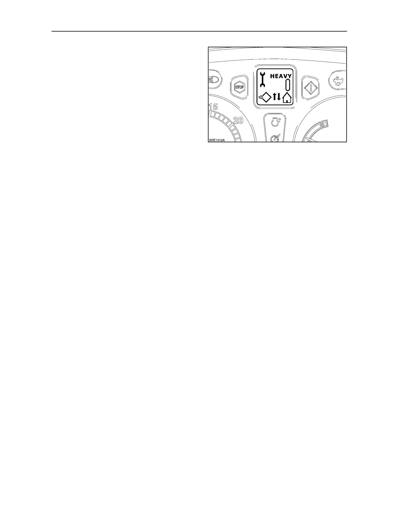
Setting a Heavy Service Reminder
Select HEAVY on the main menu and repeat the
procedure used for setting the LIGHT service
reminder.
Ten hours before the service is due the Heavy
Service symbol and the hours remaining will appear
in the DMD at ’key--on’ and will remain displayed for
4 seconds after the engine is started.
114
Time Expiry Warnings
As the time to service expires, the relevant symbol
will appear hourly in the display for 20 seconds. The
number of hours remining before the service will also
be shown and this will be accompanied by the Amber
warning light. When time to service has expired, only
the symbol will appear hourly in the display.
If required, the service time countdown may be
terminated by re--setting the Service Reminder
interval to zero or by changing the period until the
next service is due.
2--64
SECTION 2 -- CONTROLS, INSTRUMENTS AND OPERATION
TRANSMISSION OPERATION
Your tractor may be fitted with one of three
transmission options dependent on country and
specification.
12 x 12 Synchro Command
This transmission offers 12 forward and reverse
synchromesh gears selected by two shift levers
conveniently placed to the right of the driver. The
forward and reverse synchronised shuttle is
operated by a lever to the left of the steering column.
24 x 24 Dual Command
Operating in a similar manner to the 12 x 12, Dual
Command offers the additional benefit of a
hydraulically engaged underdrive for each of the
basic 12 gears. This provides 24 forward and reverse
ratios. Underdrive may be engaged on the move
without depressing the clutch pedal. A clutchless
shuttle function is also featured on the Dual
Command transmission.
16 x 16 (17 x 16) Electro Command
The Electro Command transmission has
4
powershift gears and four range gears providing 16
forward and reverse ratios. On 50 Km/h models, an
additional gear provides 17 forward ratios. When
operated simultaneously, the powershift and range
change buttons will provide clutchless changes on
the move through ratios 1--8 and 9--16 (17).
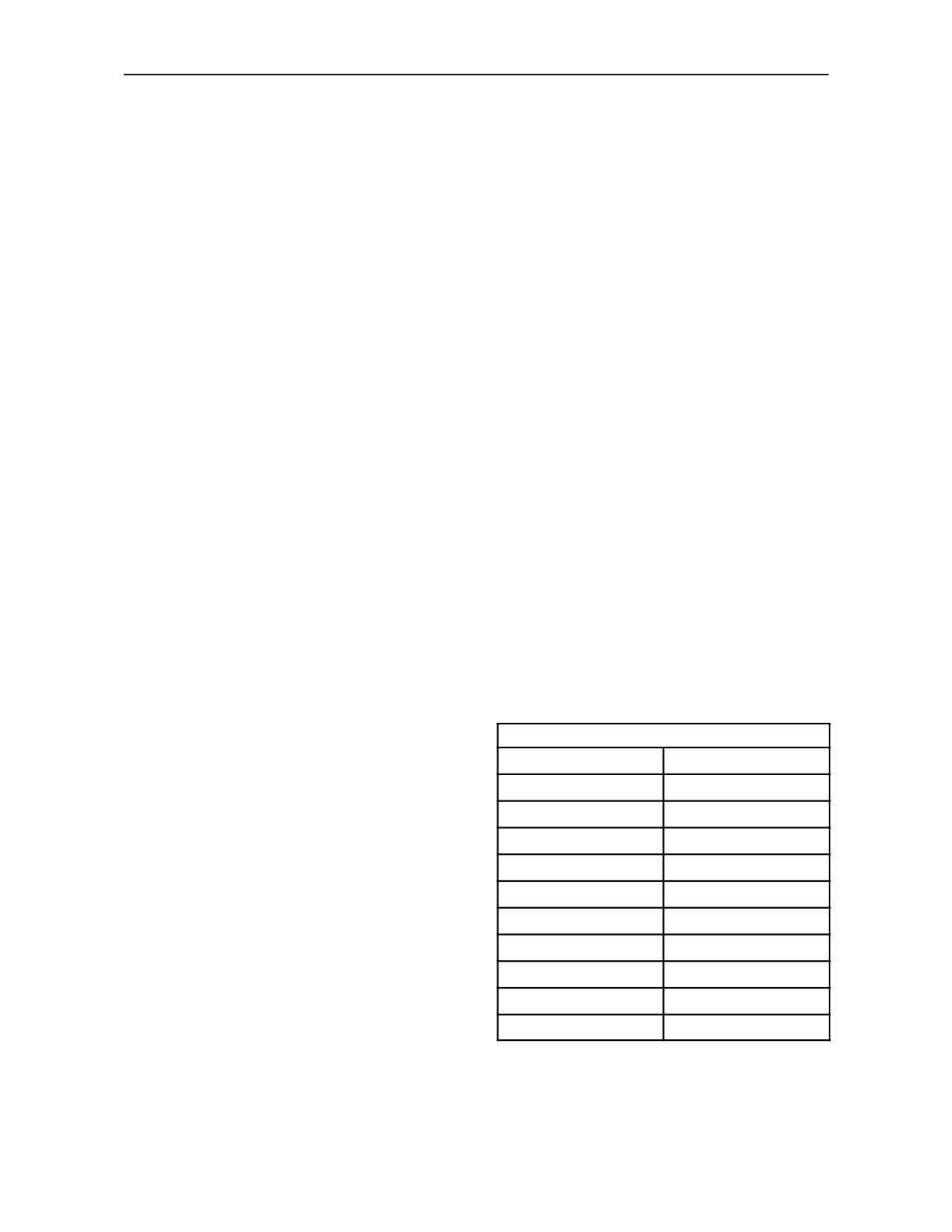
Ground Speeds
MPH/K/mh Conversion Chart
K/mh → MPH
MPH → K/mh
Ground speeds are displayed in the LCD on the
left-hand side of the instrument panel. However, as
5 → 3.1
5 → 8.0
a guide, ground speed charts for specific tyre sizes
10 → 6.2
10 → 16.0
are provided at the end of each transmission section.
15 → 9.3
15 → 24.1
If the rear tyres of your tractor are of a different size
20 → 12.4
20 → 32.1
to those shown in the charts, it may be necessary to
re--calibrate the speedometer as previously
25 → 15.5
25 → 40.2
described.
30 → 18.6
30 → 48.2
35 → 21.7
35 → 56.3
40 → 24.8
45 → 27.9
50 → 31.0
2--65
SECTION 2 -- CONTROLS, INSTRUMENTS AND OPERATION
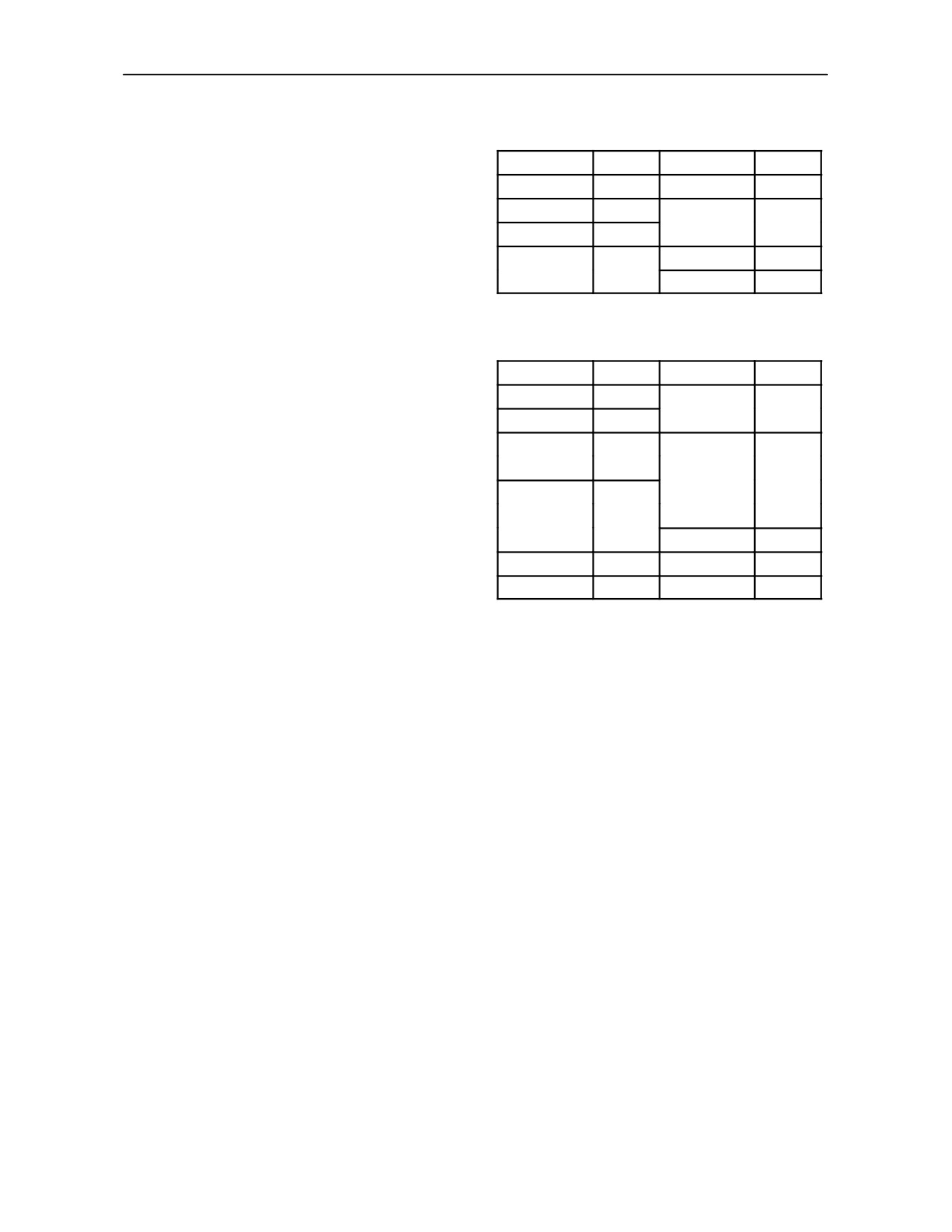
Ground Speed Conversion Chart
Models with Light Duty Rear Axle
The size of the rear tyres on your tractor may vary
Tyre Size
Factor
Tyre Size
Factor
from those shown in the ground speed charts. When
18.4R--30
0.935
480/70R--34
0.968
an alternative size of tyre is fitted, multiply the
ground speeds shown in the charts by the conversion
12.4--32
0.839
480/70R--38
1.032
factors shown:
16.9R--34
0.968
540/65R--38
1.032
13.6R--38
0.968
----
----
16.9R--38
1.032
----
----
All Models with Heavy Duty Rear Axle
Tyre Size
Factor
Tyre Size
Factor
18.4R--30
0.879
480/70R--34
0.909
12.4--32
0.788
520/70R--34
0.939
16.9R--34
0.909
480/70R--38
0.970
18.4R--34
0.939
540/65R--38
0.970
13.6R--38
0.909
650/60R--38
1.000
16.9R--38
0.970
650/65R--38
1.061
20.8R--38
1.061
320/90R--50
1.061
18.4R--42
1.061
----
----
14.9R--46
1.079
----
----
2--66
SECTION 2 -- CONTROLS, INSTRUMENTS AND OPERATION
12 x 12 SYNCHRO COMMAND TRANSMISSION
This transmission offers 12 gear ratios in forward and
reverse. Operation is by means of the main shift lever,
range lever and a forward/reverse shuttle lever.
An optional reduction gear set (creeper gears) offers
a further 8 ratios, forward and reverse.
IMPORTANT: Do not change gear or operate the
shuttle lever without depressing the clutch pedal.
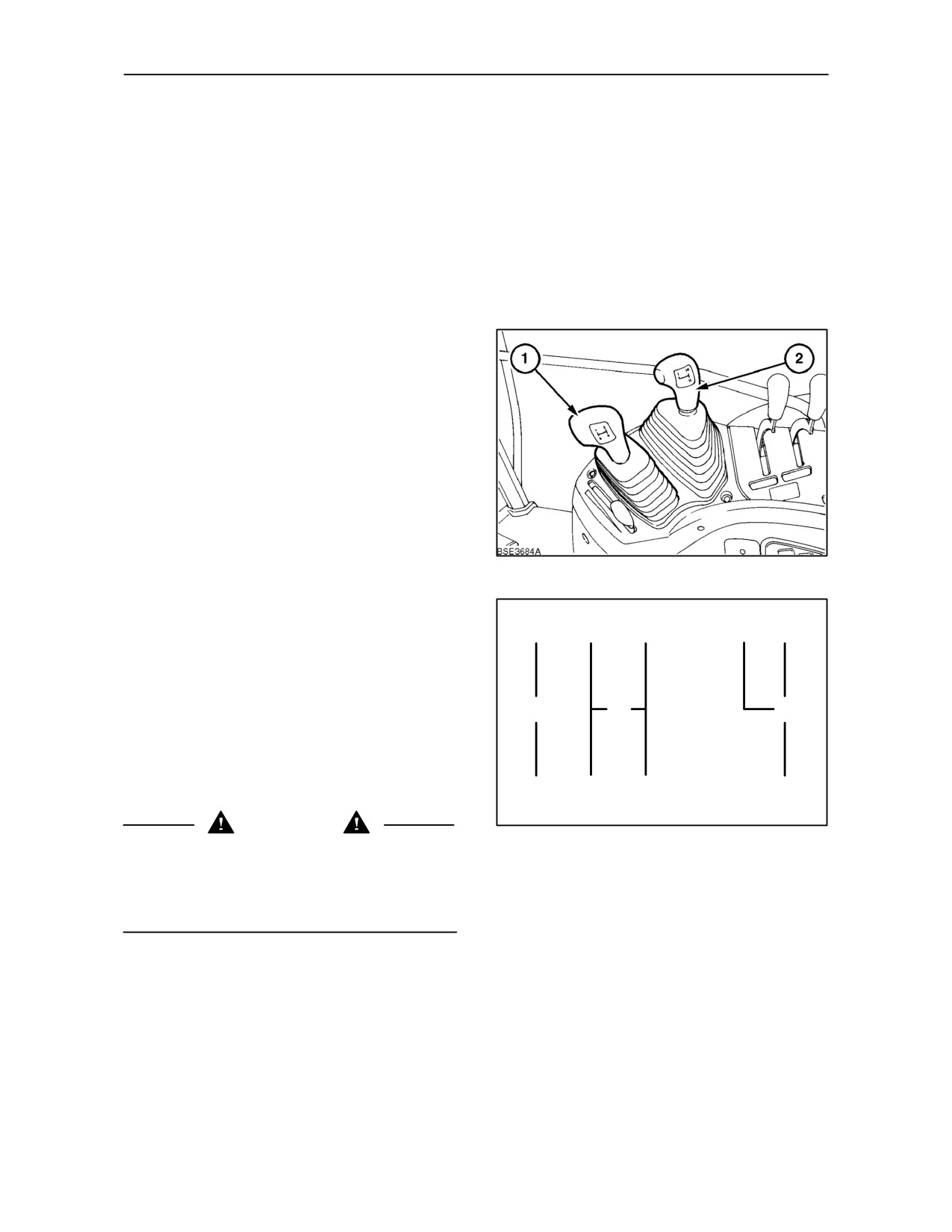
Main Shift Lever
The main shift lever (1) operates in a conventional
H-pattern and, in conjunction with the clutch pedal,
is used to select any of four gear ratios, whether the
tractor is stationary or moving.
IMPORTANT: To avoid premature wear, do not use
the clutch pedal as a footrest.
Range Lever
The right-hand lever (2) is the range lever which, in
conjunction with the clutch pedal, is used to select
115
any one of three ranges (I -- the lowest speed range,
II-- medium range and III -- the highest speed range).
This has the effect of tripling the number of gears,
F
1
3
I
III
both in forward and reverse, from 4 to 12. The design
of the transmission permits easy changes between
the medium and high ranges while the tractor is
moving. Stop the tractor to change between the
medium and low ranges.
N
N
N
IMPORTANT: If it is necessary to tow the tractor, the
range lever must be in the neutral position
otherwise damage to transmission components may
R
2
4
II
occur.
WARNING
116
To prevent inadvertent tractor movement, take care
to avoid accidental contact with the gearshift levers.
Always stop the engine, firmly apply the parking
brake and place all gear shift levers in neutral before
leaving the tractor.
2--67
SECTION 2 -- CONTROLS, INSTRUMENTS AND OPERATION
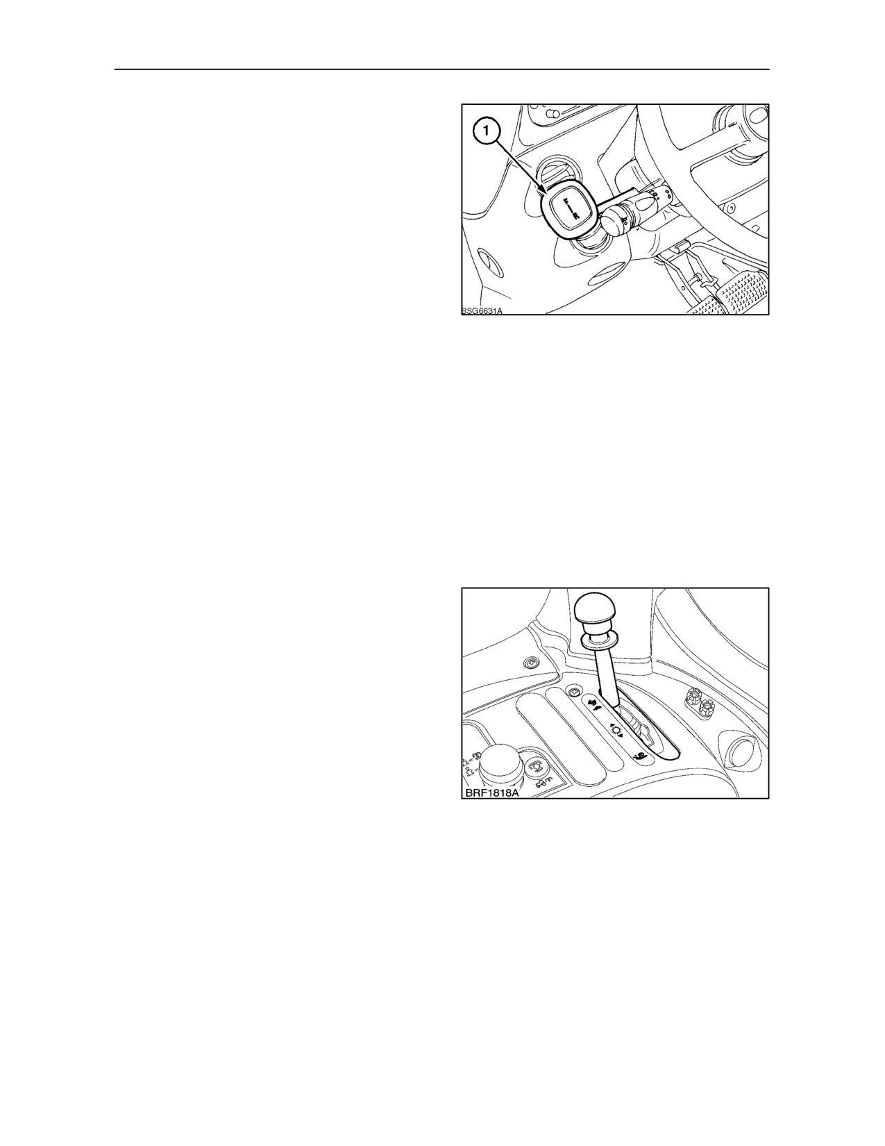
Shuttle Lever
The shuttle lever (1) is used to select forward or
reverse travel when any one of the twelve gears is
engaged, provided that the clutch pedal is
depressed. To reverse the direction of travel, reduce
engine and tractor speed to a minimum, depress the
clutch and move the shuttle lever rearwards. Re-
engage the clutch and increase engine speed, as
required.
NOTE: An interlock mechanism prevents movement
of the shuttle lever unless the clutch pedal is
depressed.The starting motor will not operate unless
117
the shuttle lever is in neutral and the clutch pedal is
depressed.
IMPORTANT: Fully depress the clutch pedal when
changing gear. Partially depressing the clutch pedal
when changing gear may result in damage to
transmission components. Also, when changing
down on the move, select the next consecutive gear
in order to avoid damage to the clutch and/or
overspeeding of the engine.
NOTE: When operating in temperatures below --18° C
(0° F) with cold transmission oil, avoid shuttle
operations, as far as practicable, until the oil has
warmed up.
Creeper Gears (where fitted)
For operations requiring extra low ground speeds,
reduction gear sets (creeper gears) are available.
As the name implies, the reduction gear set has the
effect of reducing all the ratios within the main
transmission to provide an additional twelve gears in
forward and reverse.
Creeper gear selection is denoted by the illumination
of the creeper gear symbol in the instrument panel.
118
2--68
SECTION 2 -- CONTROLS, INSTRUMENTS AND OPERATION
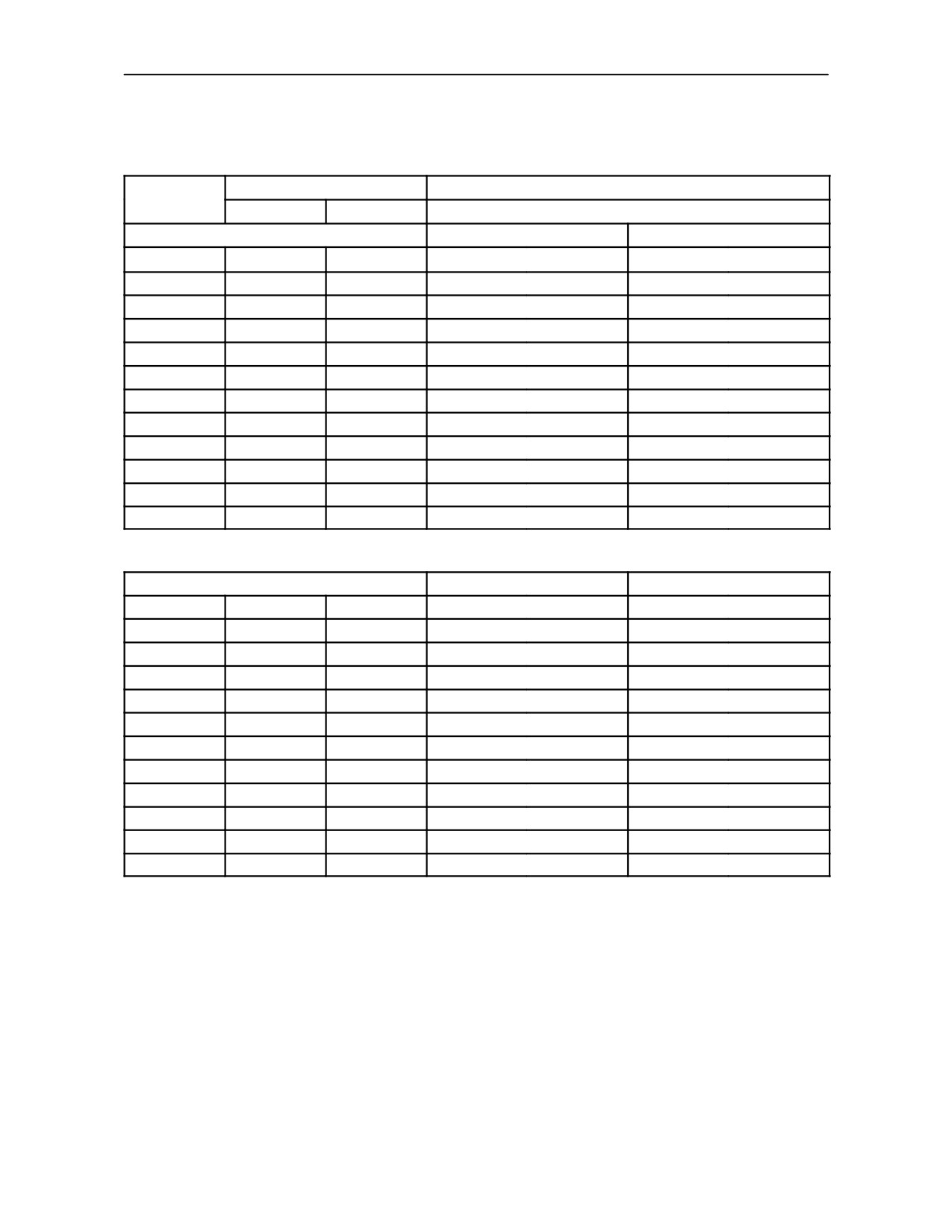
GROUND SPEEDS in Km/h and (MPH) at Rated Engine Speed (2200 rev/min)
with 30 Km/h 12 x 12 Transmission and Creeper Speeds -- Models with Light Duty Rear Axle*
Shift Lever Positions
Rear Tyre Size
Gear Ratio
Range lever
Main lever
18.4R--34, 520/70R--34
FORWARD RATIOS
Standard Speeds
Creeper Speeds
F1
L
1
2.12
(1.32)
0.21
(0.13)
F2
L
2
3.09
(1.92)
0.31
(0.19)
F3
L
3
4.19
(2.61)
0.42
(0.26)
F4
L
4
6.45
(4.03)
0.64
(0.40)
F5
M
1
4.80
(3.00)
0.48
(0.30)
F6
M
2
6.99
(4.36)
0.70
(0.43)
F7
M
3
9.49
(5.92)
0.94
(0.59)
F8
M
4
14.62
(9.12)
1.45
(0.91)
F9
H
1
10.58
(6.60)
1.05
(0.66)
F10
H
2
15.40
(9.60)
1.53
(0.95)
F11
H
3
20.90
(13.04)
2.08
(1.30)
F12
H
4
32.22
(20.09)
3.20
(2.00)
REVERSE RATIOS
Standard Speeds
Creeper Speeds
R1
L
1
3.44
(2.14)
0.34
(0.21)
R2
L
2
5.00
(3.12)
0.50
(0.31)
R3
L
3
6.79
(4.23)
0.68
(0.42)
R4
L
4
10.46
(6.53)
1.04
(0.65)
R5
M
1
7.79
(4.86)
0.77
(0.48)
R6
M
2
11.33
(7.07)
1.13
(0.70)
R7
M
3
9.73
(9.59)
1.53
(0.95)
R8
M
4
23.70
(14.78)
2.36
(1.47)
R9
H
1
10.85
(6.77)
1.08
(0.67)
R10
H
2
15.79
(9.85)
1.57
(0.98)
R11
H
3
21.44
(13.37)
2.13
(1.33)
R12
H
4
33.04
(20.61)
3.29
(2.05)
*See page 3--138
2--69
SECTION 2 -- CONTROLS, INSTRUMENTS AND OPERATION
GROUND SPEEDS in Km/h and (MPH) at Rated Engine Speed (2200 rev/min)
with 30 Km/h 12 x 12 Transmission and Creeper Speeds -- Models with Heavy Duty Rear Axle*
Shift Lever Positions
Rear Tyre Size
Gear Ratio
18.4R x 38, 520/70R--38
Range lever
Main lever
600/65R--38
FORWARD RATIOS
Standard Speeds
Creeper Speeds
F1
L
1
2.01
(1.25)
0.17
(0.10)
F2
L
2
2.92
(1.82)
0.25
(0.15)
F3
L
3
3.96
(2.47)
0.34
(0.21)
F4
L
4
6.11
(3.81)
0.52
(0.32)
F5
M
1
4.55
(2.84)
0.39
(0.24)
F6
M
2
6.62
(4.13)
0.57
(0.35)
F7
M
3
8.98
(5.60)
0.77
(0.47)
F8
M
4
13.84
(8.63)
1.19
(0.73)
F9
H
1
10.02
(6.25)
0.99
(0.61)
F10
H
2
14.58
(9.09)
1.44
(0.89)
F11
H
3
19.79
(12.34)
1.96
(1.21)
F12
H
4
30.50
(19.02)
3.03
(1.88)
REVERSE RATIOS
Standard Speeds
Creeper Speeds
R1
L
1
2.06
(1.28)
0.28
(0.17)
R2
L
2
3.00
(1.87)
0.40
(0.24)
R3
L
3
4.07
(2.54)
0.55
(0.34)
R4
L
4
6.27
(3.91)
0.85
(0.52)
R5
M
1
4.70
(2.93)
0.63
(0.39)
R6
M
2
6.79
(4.23)
0.92
(0.57)
R7
M
3
9.21
(5.75)
1.25
(0.77)
R8
M
4
14.20
(8.85)
1.94
(1.20)
R9
H
1
10.27
(6.41)
1.02
(0.63)
R10
H
2
14.95
(9.32)
1.48
(0.91)
R11
H
3
20.29
(12.66)
2.01
(1.24)
R12
H
4
31.28
(19.51)
3.10
(1.92)
*See page 3--138
2--70
SECTION 2 -- CONTROLS, INSTRUMENTS AND OPERATION
GROUND SPEEDS in Km/h and (MPH) at Rated Engine Speed (2200 rev/min)
with 40 Km/h 12 x 12 Transmission and Creeper Speeds --Models with Light Duty Rear Axle*
Shift Lever Positions
Rear Tyre Size
Gear Ratio
Range lever
Main lever
18.4R--34, 520/70R--34
FORWARD RATIOS
Standard Speeds
Creeper Speeds
F1
L
1
2.12
(1.32)
0.21
(0.13)
F2
L
2
3.11
(1.94)
0.31
(0.19)
F3
L
3
4.44
(2.77)
0.44
(0.28)
F4
L
4
6.45
(4.03)
0.64
(0.40)
F5
M
1
5.33
(3.32)
0.53
(0.33)
F6
M
2
7.80
(4.87)
0.78
(0.48)
F7
M
3
11.14
(6.95)
1.11
(0.69)
F8
M
4
16.21
(10.11)
1.61
(1.01)
F9
H
1
12.89
(8.04)
1.43
(0.89)
F10
H
2
18.89
(11.78)
2.10
(1.31)
F11
H
3
26.97
(16.82)
3.00
(1.87)
F12
H
4
39.25
(24.48)
4.36
(2.72)
REVERSE RATIOS
Standard Speeds
Creeper Speeds
R1
L
1
2.17
(1.34)
0.22
(0.13)
R2
L
2
3.19
(1.98)
0.32
(0.20)
R3
L
3
4.55
(2.82)
0.45
(0.28)
R4
L
4
6.62
(4.11)
0.66
(0.41)
R5
M
1
5.51
(3.42)
0.54
(0.34)
R6
M
2
8.00
(4.97)
0.80
(0.50)
R7
M
3
11.43
(7.10)
1.14
(0.71)
R8
M
4
16.63
(10.33)
1.65
(1.03)
R9
H
1
13.22
(8.21)
1.47
(0.92)
R10
H
2
19.37
(12.03)
2.15
(1.34)
R11
H
3
27.67
(17.19)
3.07
(1.92)
R12
H
4
40.26
(25.01)
4.47
(2.79)
*See page 3--138
2--71
SECTION 2 -- CONTROLS, INSTRUMENTS AND OPERATION
GROUND SPEEDS in Km/h and (MPH) at Rated Engine Speed (2200 rev/min)
with 40 Km/h 12 x 12 Transmission and Creeper Speeds -- Models with Heavy Duty Rear Axle*
Shift Lever Positions
Rear Tyre Size
Gear Ratio
18.4R--38, 520/70R--38
Range lever
Main lever
600/65R--38
FORWARD RATIOS
Standard Speeds
Creeper Speeds
F1
L
1
2.01
(1.25)
0.20
(0.12)
F2
L
2
2.94
(1.83)
0.29
(0.18)
F3
L
3
4.20
(2.62)
0.42
(0.26)
F4
L
4
6.11
(3.81)
0.61
(0.38)
F5
M
1
5.04
(3.14)
0.50
(0.31)
F6
M
2
7.39
(4.61)
0.73
(0.46)
F7
M
3
10.55
(6.58)
1.05
(0.65)
F8
M
4
15.35
(9.57)
1.53
(0.95)
F9
H
1
12.21
(7.61)
1.21
(0.76)
F10
H
2
17.88
(11.15)
1.78
(1.11)
F11
H
3
25.53
(15.93)
1.97
(1.23)
F12
H
4
37.16
(23.17)
3.69
(2.30)
REVERSE RATIOS
Standard Speeds
Creeper Speeds
R1
L
1
2.06
(1.28)
0.21
(0.13)
R2
L
2
3.02
(1.88)
0.30
(0.19)
R3
L
3
4.31
(2.69)
0.43
(0.27)
R4
L
4
6.27
(3.91)
0.62
(0.39)
R5
M
1
5.21
(3.25)
0.51
(0.32)
R6
M
2
7.57
(4.72)
0.75
(0.47)
R7
M
3
10.82
(6.75)
1.08
(0.67)
R8
M
4
15.74
(9.82)
1.57
(0.98)
R9
H
1
12.52
(7.81)
1.25
(0.78)
R10
H
2
18.34
(11.44)
1.82
(1.14)
R11
H
3
26.19
(16.33)
2.03
(1.26)
R12
H
4
38.11
(23.77)
3.79
(2.36)
*See page 3--138
2--72
SECTION 2 -- CONTROLS, INSTRUMENTS AND OPERATION
24 x 24 DUAL COMMAND TRANSMISSION
Dual Command transmission has an hydraulically
operated clutch pack allowing the operator to select
underdrive in any forward or reverse gear while on
the move. This effectively increases torque by 22%,
reduces tractor speed by approximately 18%.
An optional reduction gear set (creeper gears) offers
a further 8 ratios, forward and reverse.
Main Shift Lever
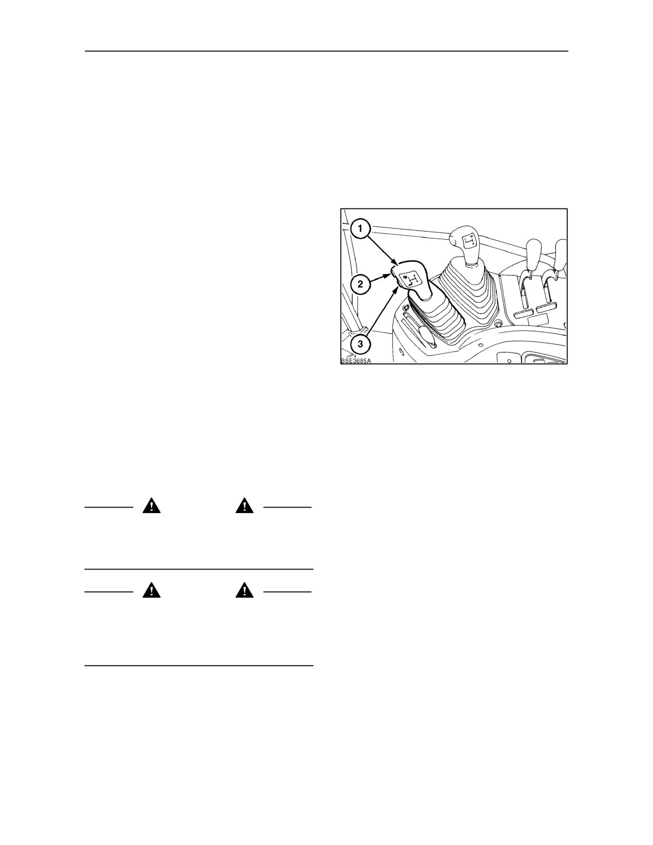
The main transmission lever (1) is provided with
electrical push buttons to actuate the Dual
Command function. Operation and function is
otherwise identical to the 12 x 12 transmission.
Underdrive is hydraulically engaged, the valve being
actuated by a solenoid controlled by push buttons (2)
and (3) on the main gear shift lever.
Press the lower switch (3) to engage Underdrive
(tortoise symbol). Press the upper switch (2) (hare
symbol) to disengage Dual Command and return to
119
direct drive.
When direct drive is engaged, the green indicator
light on the instrument panel, which has a ‘hare’
symbol, illuminates to indicate that Dual Command
is in direct drive.
IMPORTANT: A tractor with Dual Command
transmission must not be tow-started. See ‘Starting
the Tractor with Jump Leads’ in section 3.
WARNING
Always engage the parking brake before
dismounting from the tractor. Dual Command will not
prevent the tractor from rolling when the engine is
shut off.
WARNING
To prevent inadvertent tractor movement, take care
to avoid accidental contact with the gearshift levers.
Always stop the engine, firmly apply the parking
brake and place all gear shift levers in neutral before
leaving the tractor.
2--73
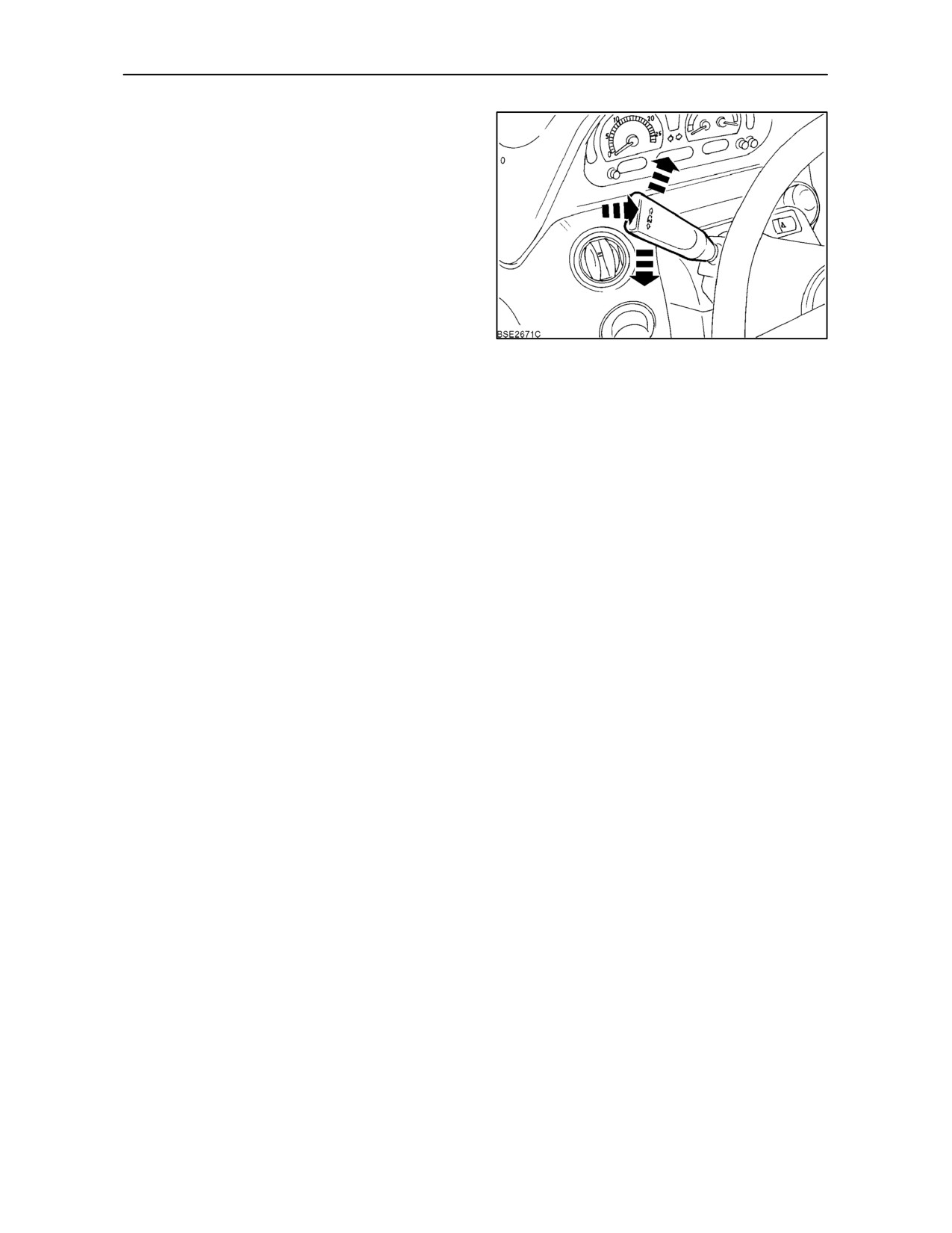
SECTION 2 -- CONTROLS, INSTRUMENTS AND OPERATION
Shuttle Lever
Selection of forward or reverse travel is by means of
an electrically operated shuttle lever, located to the
left of the steering wheel. The lever is spring-loaded
to prevent inadvertent movement, lift to select
forward or reverse drive. It is not necessary to
depress the clutch pedal when actuating the shuttle
lever.
To change from forward to reverse motion, apply the
brakes to slow the tractor, move the shuttle lever fully
rearward, and control tractor speed by means of the
throttle.
120
NOTE: Forward or reverse drive cannot be engaged
unless the operator is in the tractor seat. Additionally,
if the vehicle is moved in either direction with the
handbrake engaged, an audible alarm will be heard.
IMPORTANT: To reduce clutch damage caused by
shuttle shifting in too high a gear or at too high a
speed, a warning bleeper will be heard and the
symbol ‘N’ will flash in the instrument panel when
tractor speed is greater than 9 Km/h (5 MPH).
Auto Take Off
The Auto Take Off feature permits the operator to
NOTE: The Auto Take Off function will be disabled
engage drive without using the clutch pedal by simply
if the vehicle is at rest with the shuttle lever in the
moving the shuttle lever from neutral to the forward
neutral position and the operator leaves the seat.
or reverse position.
Should Auto Take Off be disabled for any reason, the
operator should carry out the following procedure to
The Auto Take Off function is automatically enabled
re--enable this function.
under normal starting conditions. i.e. operator in the
driving seat, clutch pedal depressed, shuttle lever in
While sitting in the seat, release the handbrake and
neutral.
cycle the clutch pedal. The vehicle will then move off
in the direction selected on the shuttle lever.
After selecting the chosen gear ranges, simply move
the shuttle lever to the forward or reverse position
Once enabled, the Auto Take Off function will
without depressing the clutch pedal. The Auto Take
continue to function as long as the operator remains
Off function will provide a controlled start from rest.
in the seat.
2--74
SECTION 2 -- CONTROLS, INSTRUMENTS AND OPERATION
Creeper Gears (where fitted)
For operations requiring extra low ground speeds,
reduction gear sets (creeper gears) are available.
The reduction gear set has the effect of reducing all
the ratios within the main transmission to provide an
additional twenty four gears in forward and reverse.
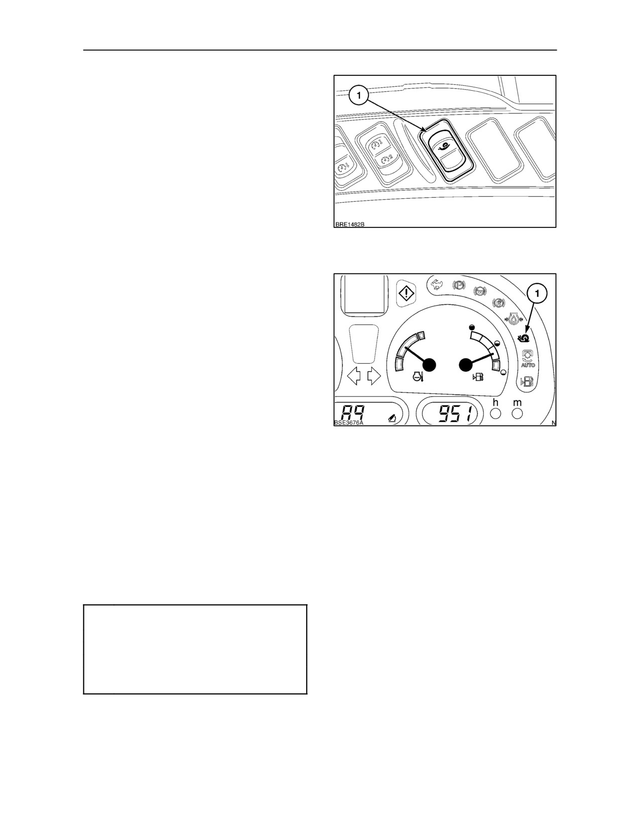
The creeper gears are selected by means of a rocker
switch (1) located on the right-hand control console.
With the engine running, clutch depressed and the
shuttle lever in neutral, apply and hold down the
121
tractor footbrakes. Momentarily depress the lower
part of the selector switch (1), Figure 121, to engage
the creeper gears.
The creep speed symbol (1) Figure 122, will appear
in the Instrument panel.
To disengage creeper gears, repeat the above
procedure and depress the selector switch again.
The creep speed symbol will cease to illuminate.
IMPORTANT: The creeper gears offer very low
ground speeds. Do not use the low gearing
advantage to apply excessive draft loads to the
tractor.
122
Error Codes
Transmission Calibration
Should a fault occur in the transmission controls,
Should transmission shifts become slow or jerky, the
causing the tractor to become disabled, an error
clutches in the transmission may require
code will be displayed in the instrument panel. If this
re--calibrating. Consult your authorised dealer.
should happen, contact your authorised dealer and
report the error code displayed.
There are a number of ’action reqired’ error codes
which can also appear in the Dot Matrix Display,
these are listed below.
Error
Code Fault
P
Park brake on, release brake lever.
N
Place the shuttle lever in neutral.
C
Wheel speed too high for creeper gears.
CP
Depress clutch pedal to enable
transmission (restore drive).
2--75
SECTION 2 -- CONTROLS, INSTRUMENTS AND OPERATION
GROUND SPEEDS in Km/h and (MPH) at Rated Engine Speed (2200 rev/min)
with 30 Km/h Transmission (24 x 24) and Creeper Speeds -- Models with Light Duty Rear Axle*
Shift Lever Positions
Rear Tyre Size
Gear Ratio
Range
Hi / Lo
18.4R--34
Main lever
lever
Button
520/70R--34
FORWARD RATIOS
Standard Speeds
Creeper Speeds
F1
L
1
Low
1.73
(1.08)
0.15
(0.10)
F2
L
1
High
2.12
(1.32)
0.19
(0.12)
F3
L
2
Low
2.52
(1.57)
0.22
(0.14)
F4
L
2
High
3.09
(1.92)
0.27
(0.17)
F5
L
3
Low
3.42
(2.14)
0.30
(0.19)
F6
L
3
High
4.19
(2.61)
0.37
(0.23)
F7
L
4
Low
5.28
(3.29)
0.47
(0.29)
F8
L
4
High
6.45
(4.03)
0.57
(0.36)
F9
M
5
Low
3.93
(2.45)
0.35
(0.22)
F10
M
5
High
4.80
(3.00)
0.42
(0.26)
F11
M
6
Low
5.71
(3.56)
0.51
(0.31)
F12
M
6
High
6.99
(4.36)
0.62
(0.39)
F13
M
7
Low
7.76
(4.84)
0.69
(0.43)
F14
M
7
High
9.49
(5.92)
0.84
(0.52)
F15
M
8
Low
11.95
(7.46)
1.06
(0.66)
F16
M
8
High
14.62
(9.12)
1.29
(0.81)
F17
H
9
Low
8.65
(5.40)
0.77
(0.48)
F18
H
9
High
10.58
(6.60)
0.94
(0.58)
F19
H
10
Low
12.59
(7.85)
1.11
(0.69)
F20
H
10
High
15.40
(9.60)
1.36
(0.85)
F21
H
11
Low
17.09
(10.66)
1.51
(0.94)
F22
H
11
High
20.90
(13.04)
1.85
(1.15)
F23
H
12
Low
26.34
(16.43)
2.33
(1.45)
F24
H
12
High
32.22
(20.09)
2.85
(1.78)
*See page
3--138
2--76
SECTION 2 -- CONTROLS, INSTRUMENTS AND OPERATION
GROUND SPEEDS in Km/h and (MPH) at Rated Engine Speed (2200 rev/min)
with 30 Km/h Transmission (24 x 24) and Creeper Speeds --Models with Light Duty Rear Axle*
Shift Lever Positions
Rear Tyre Size
Gear Ratio
Range
Hi / Lo
18.4R--34
Main lever
lever
Button
520/70R--34
REVERSE RATIOS
Standard Speeds
Creeper Speeds
R1
L
1
Low
1.79
(1.12)
0.16
(0.10)
R2
L
1
High
2.19
(1.37)
0.19
(0.12)
R3
L
2
Low
2.61
(1.63)
0.23
(0.14)
R4
L
2
High
3.19
(1.99)
0.28
(0.18)
R5
L
3
Low
3.54
(2.21)
0.31
(0.20)
R6
L
3
High
4.33
(2.70)
0.38
(0.24)
R7
L
4
Low
5.46
(3.40)
0.48
(0.30)
R8
L
4
High
6.67
(4.16)
0.59
(0.37)
R9
M
5
Low
4.06
(2.53)
0.36
(0.22)
R10
M
5
High
4.97
(3.10)
0.44
(0.27)
R11
M
6
Low
5.91
(3.69)
0.52
(0.33)
R12
M
6
High
7.23
(4.51)
0.64
(0.40)
R13
M
7
Low
8.02
(5.00)
0.71
(0.44)
R14
M
7
High
9.81
(6.12)
0.87
(0.54)
R15
M
8
Low
12.36
(7.71)
1.09
(0.68)
R16
M
8
High
15.12
(9.43)
1.34
(0.83)
R17
H
9
Low
8.95
(5.58)
0.79
(0.49)
R18
H
9
High
10.94
(6.83)
0.97
(0.60)
R19
H
10
Low
13.02
(8.12)
1.15
(0.72)
R20
H
10
High
15.92
(9.93)
1.41
(0.88)
R21
H
11
Low
17.67
(11.02)
1.56
(0.97)
R22
H
11
High
21.62
(13.48)
1.91
(1.19)
R23
H
12
Low
27.24
(16.99)
2.41
(1.50)
R24
H
12
High
33.31
(20.78)
2.94
(1.84)
*See page
3--138
2--77
SECTION 2 -- CONTROLS, INSTRUMENTS AND OPERATION
GROUND SPEEDS in Km/h and (MPH) at Rated Engine Speed (2200 rev/min)
with 30 Km/h Transmission (24 x 24) and Creeper Speeds -- Models with Heavy Duty Rear Axle*
Shift Lever Positions
Rear Tyre Size
Gear Ratio
Range
Hi / Lo
18.4R--38, 520/70R--38
Main lever
lever
Button
600/65R--38
FORWARD RATIOS
Standard Speeds
Creeper Speeds
F1
L
1
Low
1.64
(1.02)
0.16
(0.10)
F2
L
1
High
2.01
(1.25)
0.20
(0.12)
F3
L
2
Low
2.39
(1.49)
0.24
(0.15)
F4
L
2
High
2.92
(1.82)
0.29
(0.18)
F5
L
3
Low
3.24
(2.02)
0.32
(0.20)
F6
L
3
High
3.96
(2.47)
0.39
(0.25)
F7
L
4
Low
4.99
(3.12)
0.50
(0.31)
F8
L
4
High
6.11
(3.81)
0.61
(0.38)
F9
M
5
Low
3.72
(2.32)
0.37
(0.23)
F10
M
5
High
4.55
(2.84)
0.45
(0.28)
F11
M
6
Low
5.41
(3.37)
0.54
(0.34)
F12
M
6
High
6.62
(4.13)
0.66
(0.41)
F13
M
7
Low
7.34
(4.58)
0.73
(0.46)
F14
M
7
High
8.98
(5.60)
0.89
(0.56)
F15
M
8
Low
11.32
(7.06)
1.12
(0.70)
F16
M
8
High
13.84
(8.63)
1.38
(0.86)
F17
H
9
Low
8.19
(5.11)
0.81
(0.51)
F18
H
9
High
10.02
(6.25)
1.00
(0.62)
F19
H
10
Low
11.92
(7.43)
1.19
(0.74)
F20
H
10
High
14.58
(9.09)
1.45
(0.90)
F21
H
11
Low
16.18
(10.09)
1.61
(1.00)
F22
H
11
High
19.79
(12.34)
1.97
(1.23)
F23
H
12
Low
24.93
(15.55)
2.48
(1.55)
F24
H
12
High
30.50
(19.02)
3.03
(1.89)
*See page
3--138
2--78
SECTION 2 -- CONTROLS, INSTRUMENTS AND OPERATION
GROUND SPEEDS in Km/h and (MPH) at Rated Engine Speed (2200 rev/min)
with 30 Km/h Transmission (24 x 24) and Creeper Speeds -- Models with Heavy Duty Rear Axle*
Shift Lever Positions
Rear Tyre Size
Gear Ratio
Range
Hi / Lo
18.4R--38, 520/70R--38
Main lever
lever
Button
600/65R--38
REVERSE RATIOS
Standard Speeds
Creeper Speeds
R1
L
1
Low
1.70
(1.06)
0.17
(0.11)
R2
L
1
High
2.08
(1.29)
0.21
(0.13)
R3
L
2
Low
2.47
(1.54)
0.25
(0.15)
R4
L
2
High
3.02
(1.88)
0.30
(0.19)
R5
L
3
Low
3.35
(2.09)
0.33
(0.21)
R6
L
3
High
4.10
(2.56)
0.41
(0.25)
R7
L
4
Low
5.17
(3.22)
0.51
(0.32)
R8
L
4
High
6.32
(3.94)
0.63
(0.39)
R9
M
5
Low
3.84
(2.40)
0.38
(0.24)
R10
M
5
High
4.70
(2.93)
0.47
(0.29)
R11
M
6
Low
5.59
(3.49)
0.56
(0.35)
R12
M
6
High
6.84
(4.27)
0.68
(0.42)
R13
M
7
Low
7.59
(4.74)
0.75
(0.47)
R14
M
7
High
9.29
(5.79)
0.92
(0.58)
R15
M
8
Low
11.70
(7.30)
1.16
(0.73)
R16
M
8
High
14.31
(8.93)
1.42
(0.89)
R17
H
9
Low
8.47
(5.28)
0.84
(0.53)
R18
H
9
High
10.36
(6.46)
1.03
(0.64)
R19
H
10
Low
12.32
(7.69)
1.23
(0.76)
R20
H
10
High
15.07
(9.40)
1.50
(0.93)
R21
H
11
Low
16.73
(10.43)
1.66
(1.04)
R22
H
11
High
20.46
(12.76)
2.03
(1.27)
R23
H
12
Low
25.78
(16.08)
2.56
(1.60)
R24
H
12
High
31.53
(19.67)
3.14
(1.96)
*See page
3--138
2--79
SECTION 2 -- CONTROLS, INSTRUMENTS AND OPERATION
GROUND SPEEDS in Km/h and (MPH) at Rated Engine Speed (2200 rev/min)
with 40 Km/h Transmission (24 x 24) and Creeper Speeds -- Models with Light Duty Rear Axle*
Shift Lever Positions
Rear Tyre Size
Gear Ratio
Range
Hi / Lo
18.4R--34
Main lever
lever
Button
520/70R--34
FORWARD RATIOS
Standard Speeds
Creeper Speeds
F1
L
1
Low
1.73
(1.08)
0.17
(0.11)
F2
L
1
High
2.12
(1.32)
0.21
(0.13)
F3
L
2
Low
2.54
(1.58)
0.25
(0.16)
F4
L
2
High
3.11
(1.94)
0.31
(0.19)
F5
L
3
Low
3.63
(2.26)
0.36
(0.22)
F6
L
3
High
4.44
(2.77)
0.44
(0.28)
F7
L
4
Low
5.28
(3.29)
0.52
(0.33)
F8
L
4
High
6.45
(4.03)
0.64
(0.40)
F9
M
5
Low
4.35
(2.72)
0.43
(0.27)
F10
M
5
High
5.33
(3.32)
0.53
(0.33)
F11
M
6
Low
6.38
(3.98)
0.63
(0.40)
F12
M
6
High
7.80
(4.87)
0.78
(0.48)
F13
M
7
Low
9.11
(5.68)
0.91
(0.56)
F14
M
7
High
11.14
(6.95)
1.11
(0.69)
F15
M
8
Low
13.25
(8.27)
1.32
(0.82)
F16
M
8
High
16.21
(10.11)
1.61
(1.01)
F17
H
9
Low
10.54
(6.58)
1.05
(0.65)
F18
H
9
High
12.89
(8.04)
1.28
(0.80)
F19
H
10
Low
15.44
(9.63)
1.54
(0.96)
F20
H
10
High
18.89
(11.78)
1.88
(1.17)
F21
H
11
Low
22.05
(13.76)
2.19
(1.37)
F22
H
11
High
26.97
(16.82)
2.68
(1.67)
F23
H
12
Low
32.09
(20.02)
3.19
(1.99)
F24
H
12
High
39.25
(24.48)
3.90
(2.43)
*See page
3--138
2--80
SECTION 2 -- CONTROLS, INSTRUMENTS AND OPERATION
GROUND SPEEDS in Km/h and (MPH) at Rated Engine Speed (2200 rev/min)
with 40 Km/h Transmission (24 x 24) and Creeper Speeds -- Models with Light Duty Rear Axle*
Shift Lever Positions
Rear Tyre Size
Gear Ratio
Range
Hi / Lo
18.4R--34
Main lever
lever
Button
520/70R--34
REVERSE RATIOS
Standard Speeds
Creeper Speeds
R1
L
1
Low
1.79
(1.12)
0.18
(0.11)
R2
L
1
High
2.19
(1.37)
0.22
(0.14)
R3
L
2
Low
2.63
(1.64)
0.26
(0.16)
R4
L
2
High
3.21
(2.00)
0.32
(0.20)
R5
L
3
Low
3.75
(2.34)
0.37
(0.23)
R6
L
3
High
4.59
(2.86)
0.46
(0.28)
R7
L
4
Low
5.46
(3.40)
0.54
(0.34)
R8
L
4
High
6.67
(4.16)
0.66
(0.41)
R9
M
5
Low
4.50
(2.81)
0.45
(0.28)
R10
M
5
High
5.51
(3.43)
0.55
(0.34)
R11
M
6
Low
6.60
(4.11)
0.66
(0.41)
R12
M
6
High
8.07
(5.03)
0.80
(0.50)
R13
M
7
Low
9.42
(5.88)
0.94
(0.58)
R14
M
7
High
11.52
(7.19)
1.15
(0.71)
R15
M
8
Low
13.71
(8.55)
1.36
(0.85)
R16
M
8
High
16.76
(10.46)
1.67
(1.04)
R17
H
9
Low
10.90
(6.80)
1.08
(0.68)
R18
H
9
High
13.33
(8.32)
1.33
(0.83)
R19
H
10
Low
15.97
(9.96)
1.59
(0.99)
R20
H
10
High
19.53
(12.18)
1.94
(1.21)
R21
H
11
Low
22.81
(14.22)
2.27
(1.41)
R22
H
11
High
27.89
(17.40)
2.77
(1.73)
R23
H
12
Low
33.19
(20.70)
3.30
(2.06)
R24
H
12
High
40.59
(25.32)
4.04
(2.52)
*See page
3--138
2--81

SECTION 2 -- CONTROLS, INSTRUMENTS AND OPERATION
GROUND SPEEDS in Km/h and (MPH) at Rated Engine Speed (2200 rev/min)
with 40 Km/h Transmission (24 x 24) and Creeper Speeds -- Models with Heavy Duty Rear Axle*
Shift Lever Positions
Rear Tyre Size
Gear Ratio
Range
Hi / Lo
18.4R--38, 520/70R--38
Main lever
lever
Button
600/65R--38
FORWARD RATIOS
Standard Speeds
Creeper Speeds
F1
L
1
Low
1.64
(1.02)
0.16
(0.10)
F2
L
1
High
2.01
(1.25)
0.20
(0.12)
F3
L
2
Low
2.40
(1.50)
0.24
(0.15)
F4
L
2
High
2.94
(1.83)
0.29
(0.18)
F5
L
3
Low
3.43
(2.14)
0.34
(0.21)
F6
L
3
High
4.20
(2.62)
0.42
(0.26)
F7
L
4
Low
4.99
(3.12)
0.50
(0.31)
F8
L
4
High
6.11
(3.81)
0.61
(0.38)
F9
M
5
Low
4.12
(2.57)
0.41
(0.26)
F10
M
5
High
5.04
(3.14)
0.50
(0.31)
F11
M
6
Low
6.04
(3.77)
0.60
(0.37)
F12
M
6
High
7.39
(4.61)
0.73
(0.46)
F13
M
7
Low
8.62
(5.38)
0.86
(0.53)
F14
M
7
High
10.55
(6.58)
1.05
(0.65)
F15
M
8
Low
12.55
(7.83)
1.25
(0.78)
F16
M
8
High
15.35
(9.57)
1.53
(0.95)
F17
H
9
Low
9.98
(6.22)
0.99
(0.62)
F18
H
9
High
12.21
(7.61)
1.21
(0.76)
F19
H
10
Low
14.62
(9.12)
1.45
(0.91)
F20
H
10
High
17.88
(11.15)
1.78
(1.11)
F21
H
11
Low
20.88
(13.02)
2.08
(1.29)
F22
H
11
High
25.53
(15.93)
2.54
(1.58)
F23
H
12
Low
30.38
(18.95)
3.02
(1.88)
F24
H
12
High
37.16
(23.17)
3.69
(2.30)
*See page
3--138
2--82
SECTION 2 -- CONTROLS, INSTRUMENTS AND OPERATION
GROUND SPEEDS in Km/h and (MPH) at Rated Engine Speed (2200 rev/min)
with 40 Km/h Transmission (24 x 24) and Creeper Speeds -- Models with Heavy Duty Rear Axle*
Shift Lever Positions
Rear Tyre Size
Gear Ratio
Range
Hi / Lo
18.4R--38, 520/70R--38
Main lever
lever
Button
600/65R--38
REVERSE RATIOS
Standard Speeds
Creeper Speeds
R1
L
1
Low
1.70
(1.06)
0.17
(0.11)
R2
L
1
High
2.08
(1.29)
0.21
(0.13)
R3
L
2
Low
2.49
(1.55)
0.25
(0.15)
R4
L
2
High
3.04
(1.90)
0.30
(0.19)
R5
L
3
Low
3.55
(2.21)
0.35
(0.22)
R6
L
3
High
4.34
(2.71)
0.43
(0.27)
R7
L
4
Low
5.17
(3.22)
0.51
(0.32)
R8
L
4
High
6.32
(3.94)
0.63
(0.39)
R9
M
5
Low
4.26
(2.66)
0.42
(0.26)
R10
M
5
High
5.21
(3.25)
0.52
(0.32)
R11
M
6
Low
6.24
(3.89)
0.62
(0.39)
R12
M
6
High
7.64
(4.76)
0.76
(0.47)
R13
M
7
Low
8.92
(5.56)
0.89
(0.55)
R14
M
7
High
10.91
(6.80)
1.08
(0.68)
R15
M
8
Low
12.97
(8.09)
1.29
(0.80)
R16
M
8
High
15.87
(9.90)
1.58
(0.98)
R17
H
9
Low
10.32
(6.44)
1.03
(0.64)
R18
H
9
High
12.62
(7.87)
1.26
(0.78)
R19
H
10
Low
15.12
(9.43)
1.50
(0.94)
R20
H
10
High
18.49
(11.53)
1.84
(1.15)
R21
H
11
Low
21.59
(13.47)
2.15
(1.34)
R22
H
11
High
26.41
(16.47)
2.63
(1.64)
R23
H
12
Low
31.41
(19.59)
3.12
(1.95)
R24
H
12
High
38.42
(23.97)
3.82
(2.38)
*See page
3--138
2--83
SECTION 2 -- CONTROLS, INSTRUMENTS AND OPERATION
ELECTRO COMMAND TRANSMISSION
This transmission offers 16 or 17 forward, and 16
reverse ratios. An optional reduction gear set
(creeper gears) offers a further 16 ratios, forward and
reverse.
In the following text, operational information is based
on the 16 x 16 transmission (30 and 40 Km/h).
However, the
17 x 16 transmission
(50
Km/h)
functions in exactly the same way.
IMPORTANT: When travelling at high road speeds
with trailed or semi--mounted equipment attached to
the tractor, ensure the equipment is rated for 50K/mh
operation in respect to its construction, brakes and
tyres.
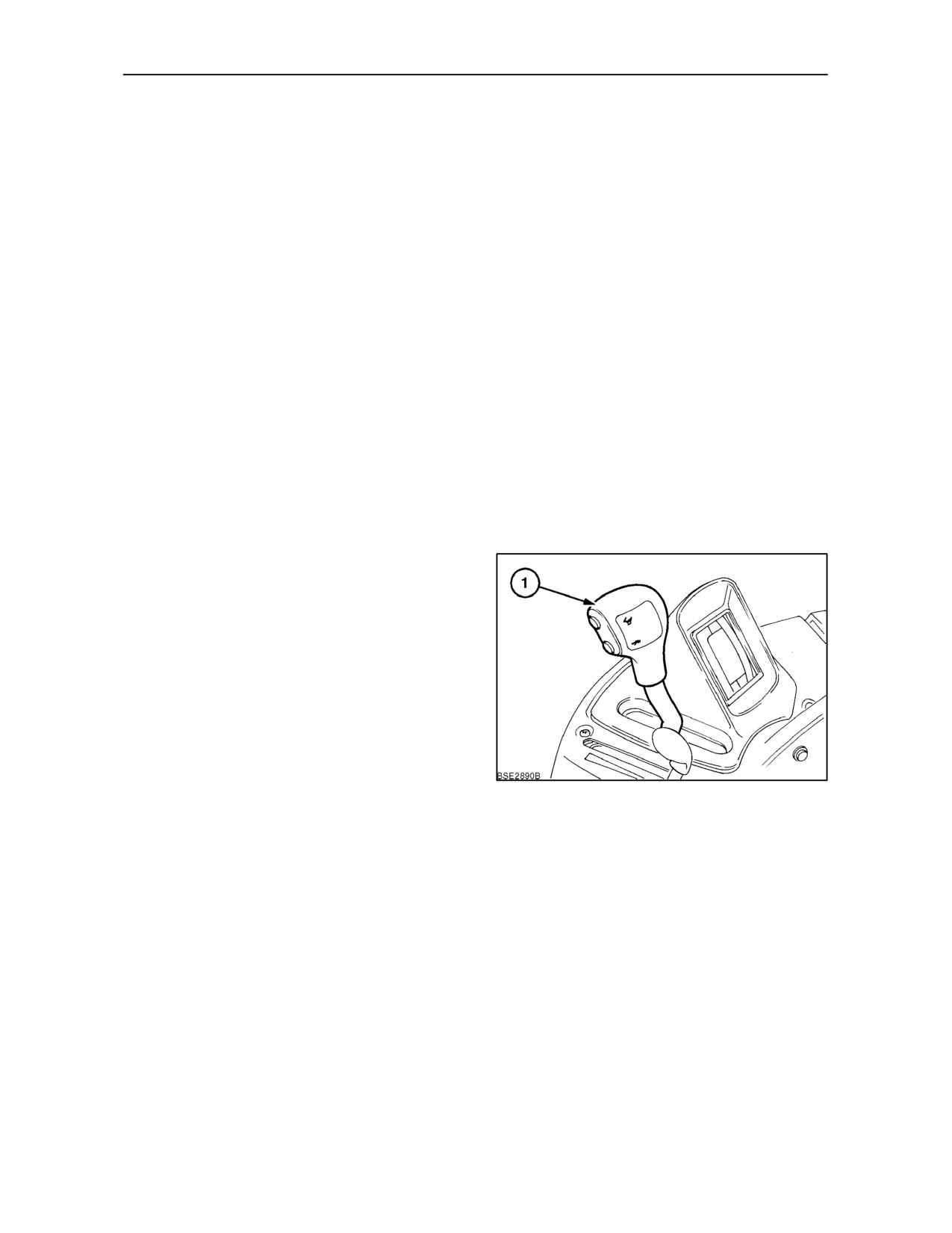
The transmission is controlled by means of a main
shift lever, two powershift buttons and a range
change button. A shuttle lever mounted to the left of
the steering wheel selects forward or reverse drive.
Transmission and throttle controls are colour-coded
orange.
This transmission provides four powershift gears in
each of the four intermediate ranges A (1--4), B
(5--8), C (9--12), and D (13--16). Clutchless shifts
between gears 4 and 5, 12 and 13 are made by using
the range button in conjunction with the powershift
buttons. Range shifts between Low and High (8th.
and 9th. gears), can only be made with the clutch
pedal fully depressed.
Main Shift Lever
The main shift lever (1), is used to select both range
gears and main gears. When selecting High or Low
ranges (moving the lever forwards or rearwards) the
123
clutch pedal must always be depressed.
With the shuttle lever in neutral and clutch pedal fully
depressed, move the main shift lever rearward into
the Low (field) range. In this range, powershift gears
1--4 or 5--8 can be selected. Move the lever fully
forward to select powershift gears 9--12 or 13--16 in
the High range. To engage neutral, move the lever to
the mid position.
2--84
SECTION 2 -- CONTROLS, INSTRUMENTS AND OPERATION
NOTE: With the tractor stationary and the shuttle
lever in forward or reverse drive, moving the main
shift lever from neutral without first depressing the
clutch pedal will result in the drive not being engaged.
Error code ‘N’ will appear in the transmission display
and an audible alarm will sound. Depress the clutch
pedal and shift the shuttle lever to neutral to clear the
display and re-engage the drive.
NOTE: To avoid power losses due to internal friction,
place both gearshift lever and the shuttle lever in
neutral when performing stationary operations.
124
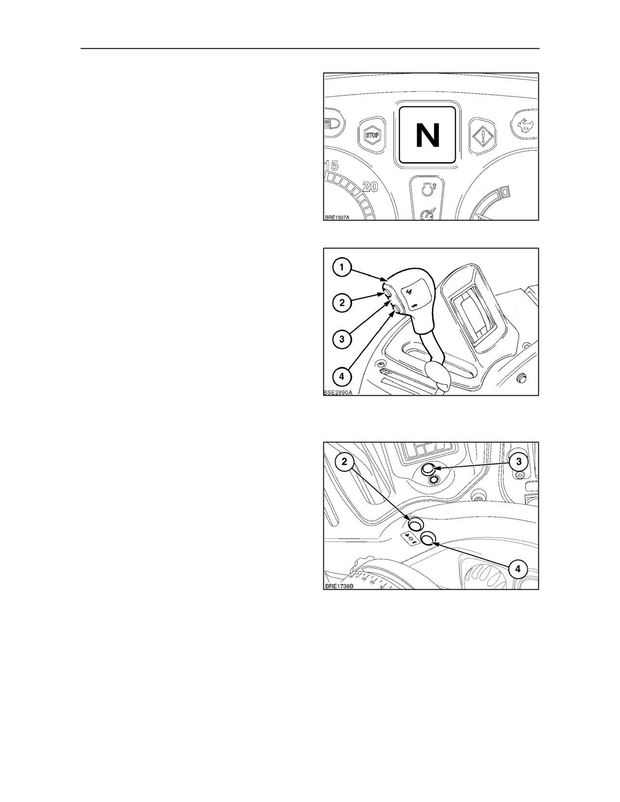
The shift lever (1), incorporates two electrical push
buttons that are used to make instantaneous up or
down powershifts. Button (2) is depressed to make
upward changes, button (4) for downward changes.
It is not necessary to use the clutch pedal to make a
powershift.
For convenience, a duplicate set of shift buttons are
located on the right--hand control panel, see
Figure 126.
To make an upward change between gears 4 and 5
hold in the intermediate range change button (3) and
depress the upshift button (2),. The change will be
125
indicated in the gear display. Use the same
procedure to change from gear 12 to 13.
Downward changes are made using the same
procedure but depressing the downshift button (4).
If preferred, the clutch pedal may be used instead of
the intermediate range change button.
NOTE: Attempting to shift from one range to another
without using the range change button or clutch
pedal will cause the audible alarm to sound.
When the main shift lever is moved forward from
neutral or from any gear within the 1--8 range, 9th.
gear will always be selected.
Conversely, if the lever is moved rearward from
126
neutral or from the 9--16 range with the tractor
moving, the speed matching function will select the
most suitable gear between 5th and 8th. To select an
alternative gear, maintain pressure on the clutch
pedal and use the powershift buttons to engage a
different gear, then release the clutch pedal.
2--85
SECTION 2 -- CONTROLS, INSTRUMENTS AND OPERATION
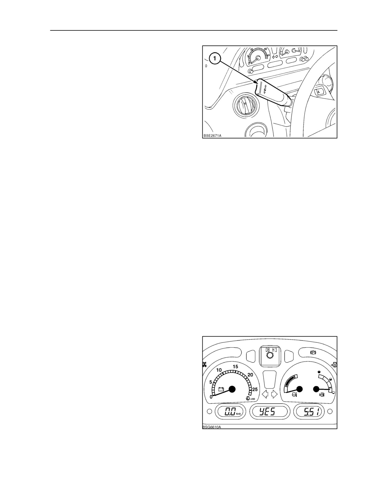
Shuttle Lever
Selection of forward or reverse travel is by means of
an electrically operated shuttle lever (1), located to
the left of the steering wheel. The lever is
spring-loaded to prevent inadvertent movement, lift
toward the steering wheel before selecting forward or
reverse drive. It is not necessary to depress the
clutch pedal when operating the shuttle lever.
NOTE: Forward or reverse drive cannot be engaged
unless the operator is in the tractor seat. Additionally,
if the vehicle is moved in either direction with the
handbrake engaged, an audible alarm will be heard
127
and ’P’ will be displayed in the Dot Matrix and Digital
Gear Displays (where fitted).
NOTE: To avoid power losses due to internal friction,
place both gearshift lever and the shuttle lever in
neutral when performing stationary operations.
To reduce clutch damage caused by shuttle shifting
in too high a gear or at too high a speed, the tractor
will slow using engine braking and the transmission
will then downshift to the lowest gear within the
selected intermediate range before changing
direction.
Shuttle Mode
During normal shuttle operations the same gear is
used for both forward and reverse. However, if 13th
gear or above is selected, the shuttle gear will be 9th.
With Shuttle Mode selected, the electronic control
unit for the transmission is able to memorise shuttle
gear combinations within a range of gears. To
activate Shuttle Mode, carry out the following
procedure.
• With the key start off, move the shuttle lever to
the reverse position. Depress and hold the
transmission upshift button and turn the key start
on. Do not start the engine.
• The transmission symbol and DB H3 will appear
in the dot matrix display and the centre LCD will
show ’no’ or ’YES’. Release the upshift button.
•
’no’ indicates memory function is disabled, ’YES’
shows the memory function is activated.
• Use the upshift and downshift buttons to toggle
between ’no’ and ’YES’. With the appropriate
128
selection made, turn the key start off and return
the shuttle lever to neutral.
2--86
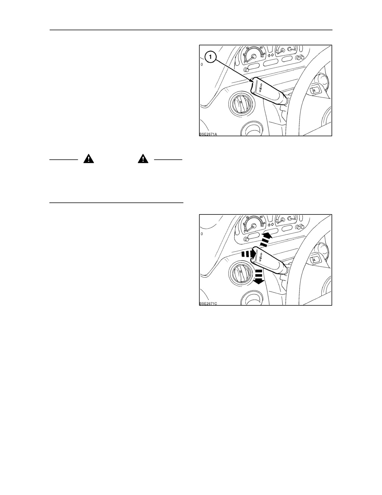
SECTION 2 -- CONTROLS, INSTRUMENTS AND OPERATION
Setting the Forward/Reverse Shuttle Gear
Start the engine and, with the clutch pedal
depressed, place the shuttle lever (1) in the forward
position. Do not release the clutch pedal. Using the
upshift/downshift buttons, set the forward gear.
Move the shuttle lever into reverse and repeat the
procedure to set the reverse gear. With the forward
and reverse gears set, return the shuttle lever to
neutral and release the clutch pedal. Shuttle Mode is
now activated.
NOTE: Selecting the shuttle gear with the lever in
neutral will result in the same ratio being set for both
129
forward and reverse.
WARNING
To prevent inadvertent tractor movement, always
stop the engine, place the shuttle lever in neutral and
firmly apply the parking brake before leaving the
tractor. The transmission will not prevent the tractor
from rolling when the engine is shut off.
Auto Take Off
The Auto Take Off feature permits the operator to
engage drive without using the clutch pedal by simply
moving the shuttle lever from neutral to the forward
or reverse position.
The Auto Take Off function is automatically enabled
under normal starting conditions. i.e. operator in the
driving seat, clutch pedal depressed, shuttle lever in
neutral.
After selecting the appropriate gear ranges with the
main shift lever simply move the shuttle lever to the
forward or reverse position without depressing the
130
clutch pedal. The Auto Take Off function will provide
a controlled start from rest.
NOTE: The Auto Take Off function will be disabled
if the vehicle is at rest with the shuttle lever in the
neutral position and the operator leaves the seat.
Should Auto Take Off be disabled for any reason, the
operator should carry out the following procedure to
re--enable this function.
While sitting in the seat, release the handbrake and
cycle the clutch pedal. The vehicle will then move off
in the direction selected on the shuttle lever.
Once enabled, the Auto Take Off function will
continue to function as long as the operator remains
in the seat.
2--87
SECTION 2 -- CONTROLS, INSTRUMENTS AND OPERATION
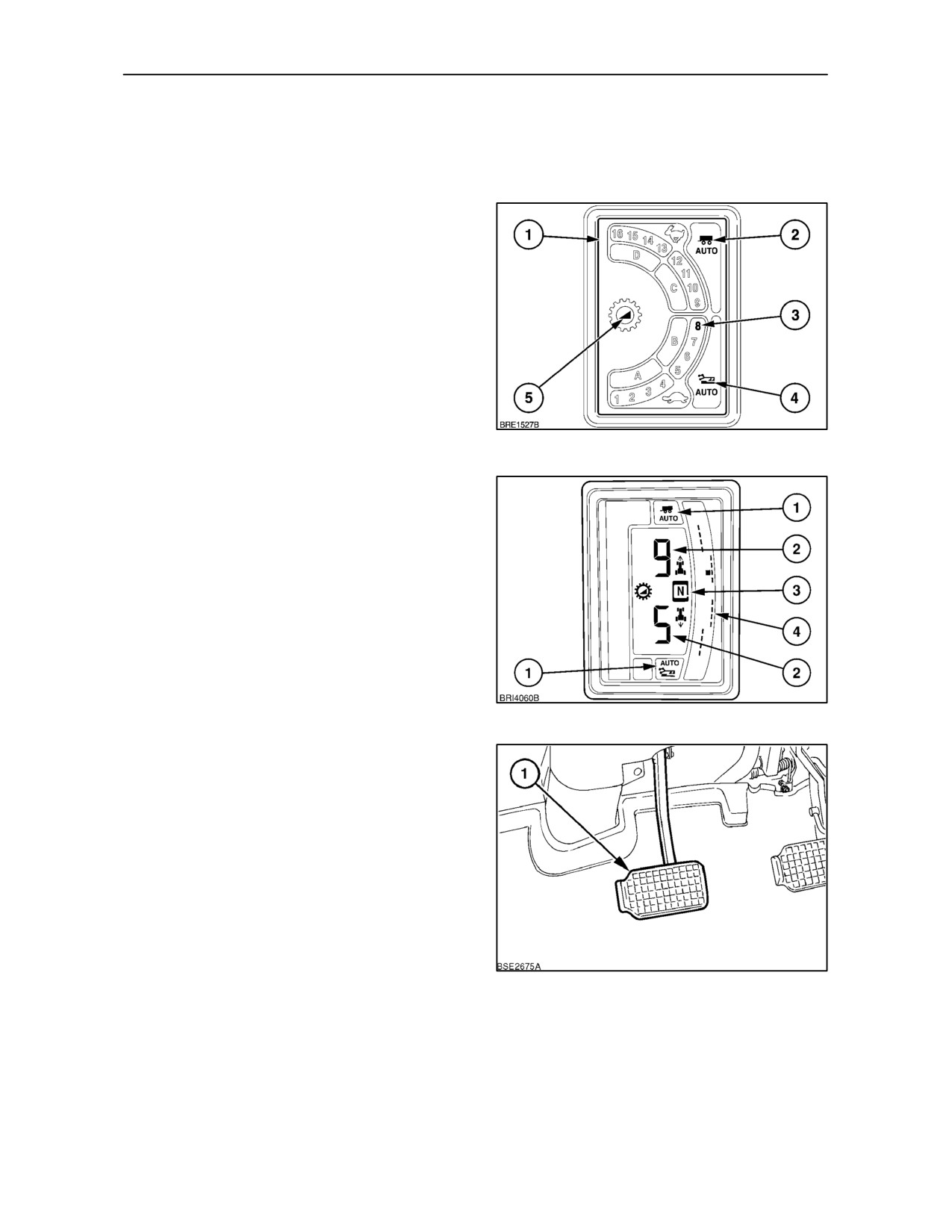
Gear Displays
Dependent upon tractor specification, two types of
gear display may be fitted.
LED Gear Display
An illuminated display (1), to the right of the main shift
lever indicates the gear selected.
As each gear is selected, the appropriate number (3)
will be illuminated in the display. With Auto Shift
engaged, the symbols for Active Road (2) and Active
Field (4) will also be illuminated. When changing the
Auto Shift point, symbol (5) will flash during the
programming procedure.
NOTE: Auto Shift is an option and may not be fitted
to your tractor.
131
Digital Gear Display
The digital display provides a comprehensive range
of information that includes:
Field and road Auto Shift (1) symbols.
Forward and reverse gears (2). The display
shows the current forward gear and the
corresponding reverse or ’shuttle’ gear.
Shuttle lever position. Forward, neutral and
reverse (3).
Gear span for each range (4).
132
Clutch Pedal
It is not necessary to use theclutch pedal(1) tomake
a powershift or when shuttle shifting
(changing
direction between forward and reverse). Use of the
clutch is recommended for positioning the tractor
when attaching equipment or operating in confined
spaces when the low gears are not slow enough, at
moderate/low engine speeds, to give precise control.
IMPORTANT: To avoid premature clutch wear, do
not use the clutch pedal as a footrest.
NOTE: There may be occasions when error codes
133
’N’ or ’CP’ flash in the Dot Matrix and Digital Gear
Displays (where fitted). Should this occur, move
shuttle lever to neutral (’N’) or cycle the clutch pedal
(’CP’) to clear the error.
2--88
SECTION 2 -- CONTROLS, INSTRUMENTS AND OPERATION
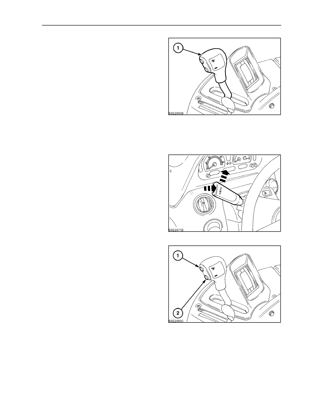
Driving the Tractor
With the main shift and shuttle levers in neutral,
depress the clutch pedal and start the engine.
NOTE: A neutral start switch prevents operation of
the starting motor unless the shuttle lever is in neutral
and the clutch pedal is depressed.
For forward travel, with the engine idling, depress the
clutch pedal and move the range lever (1), forward
to the High range or rearward to the Low range, as
required.
134
When the tractor is initially started and the main shift
lever placed in gear, the electronic control will
automatically select the appropriate powershift ratio
for a smooth pull away, as follows:
Gear Lever Positions
Ratio Selected
Field range (Low), 1 to 8
5th. gear
Road range (High), 9 to 16
9th. gear
For forward travel, with the engine idling, pull the
shuttle lever, toward the steering wheel, against light
spring-pressure, and move it up. It is not necessary
to depress the clutch pedal.
IMPORTANT: To select 14th gear or above, the
tractor must be travelling at a suitable speed before
the higher gears will engage. 14th gear or above
cannot be engaged when the tractor is stationery.
135
Once moving, press the upshift button (1), three
times and gears 6,
7 and 8 will be selected in
sequence. Alternatively, hold the button in and the
transmission will make sequential gear changes at
1.75 second intervals until the button is released or
8th. gear is reached. Use the downshift button (2) in
the same manner to make down shifts.
IMPORTANT: Downshifts of either one or more
gears, cannot be made if the tractor engine speed is
too high. To downshift, reduce tractor speed
(and
therefore engine speed) before attempting to
downshift.
136
IMPORTANT: Always use the clutch pedal when
changing between ranges 8th and 9th gears.
NOTE: When operating in temperatures below --18°
C (0° F) with cold transmission oil, avoid excessive
shuttle operations until the oil has warmed up.
2--89
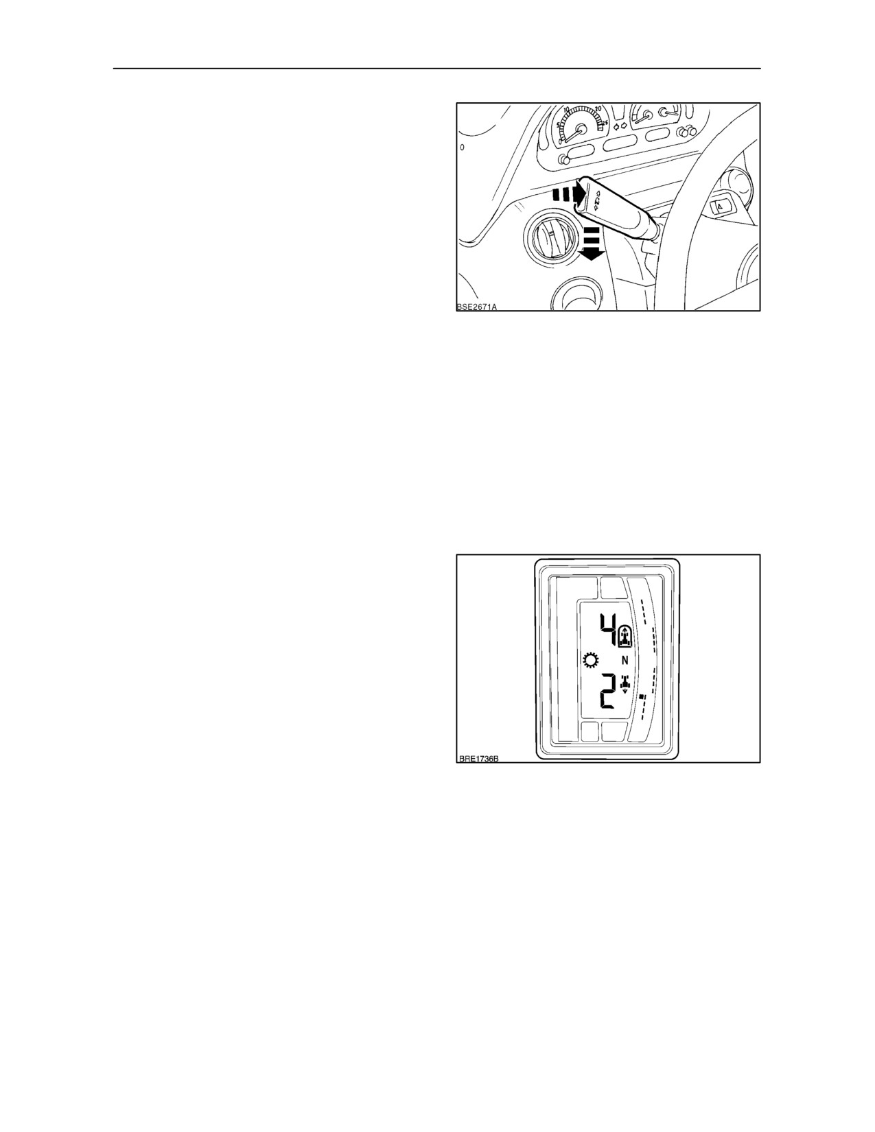
SECTION 2 -- CONTROLS, INSTRUMENTS AND OPERATION
To reverse the direction of travel pull the shuttle lever
toward the steering wheel, then move it down.
Transmission output speed and clutch pack
engagement are automatically monitored to take up
the drive smoothly in the opposite direction. Control
tractor speed by means of the throttle.
NOTE: If, for example, 3rd. gear is selected in
forward travel, then the same ratio will be selected
when the shuttle lever is moved to the reverse travel
position.
If it is necessary to hillstart with a heavy trailer in low
range then, when 8th. speed is reached, change to
137
the high range, the transmission will automatically
select the lowest ratio (9th.) in the high range.
When starting off in the highest range, the
transmission will always try to set off in 9th. gear. If
required, this feature may be overridden and a higher
gear selected by partially releasing the clutch then
powershifting up to the required gear before the
clutch ‘bite’ point is reached.
IMPORTANT: A tractor with electronic transmission
cannot be tow-started and must not be towed other
than to remove it from a field or onto a trailer or truck.
Changing the Shuttle (reverse) Gear
(Digital Gear Display Only)
For certain applications it may be beneficial to
change the reverse gear ratio from the one normally
selected when shuttling i.e. 4th forward gear will be
matched by 4th reverse gear. If required, a reverse
ratio up to three gears higher, or lower, may be set
providing they are within the same range.
To select an alternative reverse ratio to the default
gear i.e. 4th, move the shuttle lever into reverse and,
with the tractor moving select 2nd gear using the
downshift button. The transmission will now
automatically select
2nd gear when moving the
138
shuttle lever into reverse.
This procedure may be applied in gear ranges 1--4
and 5--8. When moving from one range to another,
either upwards or downwards, the default reverse
gear will always be selected until the operator
chooses an alternative ratio.
When operating in the higher ratios 13--16, the
default reverse gear will always be 9th unless a lower
ratio is selected by the operator.
2--90
SECTION 2 -- CONTROLS, INSTRUMENTS AND OPERATION
Speed Matching
Speed matching will normally only permit a downshift
to a lower gear. It will however, select a higher gear
if the the engine attempts to overspeed.
When travelling on the road in High range, gears 13
to 16, the transmission will automatically select a
gear to match engine speed to road speed if the
following method is adopted:
To downshift: Decrease engine speed, depress the
clutch pedal while simultaneously increasing engine
speed by pressing the foot throttle further down.
When the clutch pedal is released, the transmission
will automatically select a lower gear (provided 13th.
speed is not already selected) matching engine
speed to road speed.
NOTE: When operating in Auto Shift high range, the
lowest downshift gear will become 9th, see text on
Auto Shift.
In high range, the operator can manually select
another gear without affecting the speed matching
function.
With the range lever placed in low, speed matching
will operate down to 5th gear.
NOTE: The speed matching function will be disabled
if the operator manually selects a gear when in the
low range.
2--91
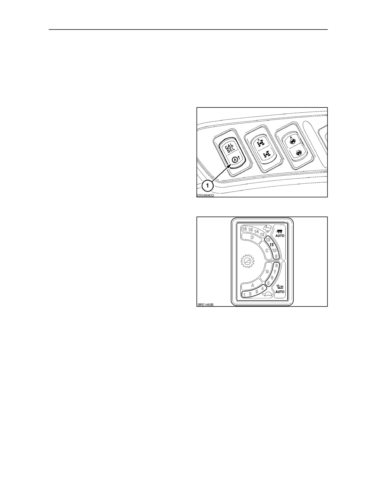
SECTION 2 -- CONTROLS, INSTRUMENTS AND OPERATION
Auto Shift Function
(Active Electro Command Only)
With Auto Shift engaged, the transmission on your
tractor is able to make automatic gearshifts, both up
and down, within a 4 gear span based on speed and
load. This can be extended to an 8 gear auto shift in
the high range for road use.
Auto Shifting in Active Field Gears
In Active Field, auto shifts can be made within gear
spans 1--4 or 5--8. With the main shift lever in the low
range (lever fully rearward), momentarily depress
the Auto Shift button (1). The Active Field symbol
(plough) will appear in the gear display and the Auto
switch will illuminate to confirm engagement.
Moving off in
1st gear, the transmission will
automatically upshift through gears 2 and 3 until 4th
gear is engaged. To Auto Shift through gears 5 to 8,
select 5th gear using the range change button and
depress the Auto Shift button again, the transmission
139
will now automatically upshift through gears 5 to 8.
As the tractor speed reduces, or the load on the
engine increases, the transmission will automatically
downshift to a lower gear.
If necessary, Active Field can be extended to include
gears 9 to 12. To engage, move the main shift lever
fully forward to select any gear in the 9 to 12 range,
then depress the Auto Shift button again. To confirm
engagement, both Active Field and Active Road
symbols will illuminate.
In ranges 1--4, 5--8 and 9--12, Auto Shift may be
linked to 3--point hitch operation. Raising the 3--point
hitch with the fast raise switch will put Auto Shift into
140
standby mode, lowering the hitch will re--activate the
Auto Shift function.
NOTE: If the 3--point hitch was in the raised position
when the Auto Shift function was activated and has
not been moved, then Auto Shift will operate without
lowering the hitch.
Auto Shift will also enter standby mode if the clutch
pedal is depressed or the shuttle lever is moved from
the forward drive position.
To cancel Auto Shift press and release the switch or
operate the upshift or downshift button.
NOTE: When using engine braking to slow the
tractor, operating the upshift or downshift buttons will
not disable Auto Shift unless the selected gear is
outside the Auto Shift range.
2--92
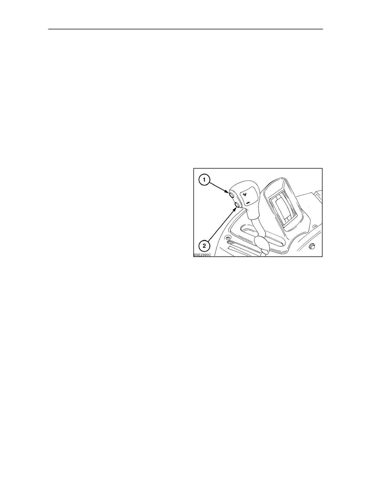
SECTION 2 -- CONTROLS, INSTRUMENTS AND OPERATION
Changing the Active Field Auto Shift Gear
Span
In some field operations it may be beneficial to
reduce the number of Auto Shift gears in the span to
provide a more consistent tractor speed or engine
speed.
The Active Field Auto Shift function normally
operates within a four gear span, such as 1--4, 5--8
or 9--12. However, the number of auto shifts within a
selected range may be reduced from a 4 gear span
to a 3, or a 2 gear span as required.
NOTE: All adjustments to the Auto Shift span must
be made with the tractor moving and the relative Auto
Shift range selected.
NOTE: Changes made to the Auto Shift gear span
will not be retained at key--off.
Reducing the gear span upper limit: Increase
tractor speed until the current Auto Shift upper gear
is engaged then momentarily depress the downshift
button (2). The transmission will downshift one gear
which becomes the new upper limit Auto Shift gear.
To reduce the span further, depress the downshift
button again.
Raising the gear span upper limit: Increase
tractor speed until the upper gear is engaged then
momentarily depress the upshift button
(1).
141
Providing the currently engaged gear is not the
highest in the range, the transmission will upshift to
the next gear. This becomes the new Auto Shift
upper limit gear.
Reducing the gear span lower limit: Slow the
tractor until the lowest Auto Shift gear is engaged and
depress the downshift button (2) once. Providing the
currently engaged gear is not the lowest in the range,
the transmission will downshift one gear. This
becomes the new lower limit Auto Shift gear.
Raising the gear span lower limit: Reduce tractor
speed until the lowest Auto Shift gear is engaged and
momentarily depress the upshift button (2). The
transmission will upshift one gear, this becomes the
new lower limit Auto Shift gear.
2--93