New Holland T6010, T6020, T6030, T6050, T6070 Delta and Plus Tractors. Operator's Manual - page 1
T6010
T6020
T6030
T6050
T6070
Delta and Plus Tractors
OPERATOR’S MANUAL
Electro-magnetic Interference (EMC)
This tractor complies strictly with the European Regulations on electro-magnetic
emissions. However, interference may arise as a result of add-on equipment which
may not necessarily meet the required standards. As such interference can result in
serious malfunction of the unit and/or create unsafe situations, you must observe the
following:
• Ensure that each piece of non-New Holland equipment fitted to the tractor bears
the CE mark.
• The maximum power of emission equipment (radio, telephones, etc.) must not
exceed the limits imposed by the national authorities of the country where you
use the tractor.
• The electro-magnetic field generated by the add-on system should not exceed
24 V/m at any time and at any location in the proximity of electronic components.
Failure to comply with these rules will render the New Holland warranty null and void.
CONTENTS
Title
Page
Section 1 -- General Information and Safety
To the Owner
1--1
End User Licence Agreement Terms
1--2
Product Identification
1--3
Ecology and the Environment
1--6
Safety Precautions
1--7
Safety Decals
1--14
International Symbols
1--19
Airborne Noise Emission
1--20
Section 2 -- Controls, Instruments and Operation
Cab
2--7
Seats
2--25
Handbrake, Throttle and Foot Controls
2--32
Instrument Console
2--34
Analogue/Digital Instruments
2--37
Synchro Command Transmission (12 x 12)
2--67
Dual Command Transmission (24 x 24)
2--73
Electro Command Transmission (16 x 16)
2--84
Differential Lock and Four Wheel Drive
2--102
Section 3 -- Field Operation
Important Information
3--2
Using Jump Leads (Booster Cables)
3--4
Starting the Engine
3--5
Stopping the Engine
3--10
Fast Steer
3--12
Rear Power Take--Off
3--14
Front Power Take--Off and Hydraulic Lift
3--33
Mechanical Lower Link Sensing Hydraulics
3--41
Electronic Draft Control
3--47
Remote Control Valves
3--59
Electro--Hydraulic Remote Control Valves
3--69
Three--point Linkage
3--83
Quick Hitch
3--90
Linkage Stabilisers
3--92
Drawbars and Towing Attachments
3--97
Hydraulic Trailer Brakes
3--113
Air-Operated Trailer Brakes
3--115
Front Wheel Track Adjustment
3--121
Rear Wheel Track Adjustment
3--128
Ballasting and Tyres
3--135
Section 4 -- Lubrication and Maintenance
General Information
4--1
Guard Removal
4--5
Lubrication and Maintenance Chart
4--10
Servicing: When Warning Lights Illuminate
4--11
10--hour/daily service
4--14
50--hour service
4--17
100--hour service
4--27
300--hour service
4--27
600--hour service
4--31
1200--hour/12 month service
4--38
1200--hour/24 month service
4--43
1800--hour service
4--50
Every 3 years
4--51
General Maintenance -- as required
4--52
Section 5 -- Fault Finding
Introduction
5--1
Engine
5--2
Transmission -- 12 x 12 Synchro Command
5--5
Transmission -- 24 x 24 Dual Command
5--6
Transmission -- 16 x 16 (17 x 16) Electro Command
5--7
Hydraulics
5--8
Three-point lift
5--9
Brakes
5--10
Cab
5--10
Electrical
5--11
Section 6 -- Vehicle Storage
6--1
Section 7 -- Accessories
Engine Coolant Immersion Heater
7--2
Transmission Oil Heater
7--2
40 Amp Socket and Cable
7--3
Auxiliary Headlights
7--3
Battery Isolator Switch
7--4
Loader Subframe and Control Valve (Joystick)
7--5
Section 8 -- Specification
General Dimensions
8--2
Vehicle Weights
8--6
Lubricant and Fluid Capacities
8--8
Engine
8--9
Fuel System
8--9
Cooling System
8--10
Transmission Options
8--10
Brakes
8--11
Rear Power Take-Off
8--11
Front Power Take-Off
8--12
Steering
8--12
Maximum Operating Angle
8--12
Hydraulic System
8--13
Rear Three-Point Lift
8--14
Remote control valves
8--20
Front Power Lift
8--20
Front Remote Valves
8--21
Electrical Equipment
8--21
Hardware Torque Tables
8--22
Section 9 -- First 50--hour Service Forms
9--1
Section 10 -- Index
10--1
SECTION 1
GENERAL INFORMATION AND SAFETY
TO THE OWNER
SAFETY
GENERAL
Pages 1--7 to 1--13 inclusive list the precautions to
be observed to ensure your safety and the safety of
This Manual has been prepared to assist you in the
others. Read the safety precautions and follow the
correct procedure for running--in, driving and
advice offered before operating the tractor.
operating and for the maintenance of your new
tractor. Read this Manual carefully. Your tractor is
FIRST 50 HOUR SERVICE
intended for use in normal and customary
agricultural applications.
In Section 9, at the back of this Manual, you will find
the 50--hour service reports.
If at any time you require advice concerning your
tractor, do not hesitate to contact your authorised
After you have operated the tractor for 50 hours, take
dealer. He has factory trained personnel, genuine
your tractor, together with this Manual, to your dealer.
manufacturers’ parts and the necessary equipment
He will then perform the factory recommended 50
to carry out all your service requirements.
hour service and complete the service report sheets
(pages 9--1 and 9--3). The first sheet (page 9--1) is the
Your tractor has been designed and built to give
dealer’s copy and should be removed by the dealer
maximum performance, economy and ease of
after the service has been carried out. The second
operation under a wide variety of operating
sheet
(page
9--3) is your copy of the service
conditions. Prior to delivery, the tractor was carefully
performed. Ensure that you and the dealer sign
inspected, both at the factory and by your dealer to
both copies.
ensure that it reaches you in optimum condition. To
maintain this condition and ensure trouble--free
SERVICE PARTS
operation, it is important that the routine services, as
specified in Section 4 of this Manual, are carried out
at the recommended intervals.
It should be pointed out that genuine parts have been
examined and approved by the Company. The
installation and/or use of
‘non-genuine’ products
OPERATORS MANUAL STORAGE
could have negative effects upon the design
characteristics of your tractor and thereby affect it’s
A storage pocket for the Operators Manual can be
safety. The Company is not liable for any damage
found on the rear of the seat. The manual should be
caused by the use of ‘non--genuine’ parts and
kept in this pocket at all times when not in use.
accessories. Only genuine New Holland
replacement parts should be used. The use of
CLEANING THE TRACTOR
non-genuine parts may invalidate legal approvals
associated with this product.
Your tractor is a state-of-the-art machine with
sophisticated, electronic controls. This should be
It is prohibited to carry out any modifications to the
borne in mind when cleaning the tractor, particularly
tractor unless specifically authorised, in writing, by
if using a high pressure washer. Even though every
the After Sales Service department of the Company.
precaution has been taken to safeguard electronic
components and connections, the pressure
generated by some of these machines is such that
WARRANTY
complete protection against water ingress cannot be
guaranteed.
Your tractor is warranted according to legal rights in
your country and the contractual agreement with the
When using a high pressure washer, do not stand too
selling dealer. No warranty shall, however, apply if
close to the tractor and avoid directing the jet at
the tractor has not been used, adjusted and
electronic components, electrical connections,
maintained according to the instructions given in the
breathers, seals, filler caps, etc. Never direct a cold
Operator’s Manual.
water jet at a hot engine or exhaust.
1--1
SECTION 1 -- GENERAL INFORMATION AND SAFETY
END USER LICENCE AGREEMENT TERMS
•
You have acquired a device (”DEVICE”) that includes Software licensed by CHN America LLC from Microsoft
Licensing, GP or its affiliates (”MS”). Those installed software products of MS origin, as well as associated
media, printed materials, and “online” or electronic documentation (”SOFTWARE”) are protected by
international intellectual property laws and treaties. The SOFTWARE is licensed, not sold. All rights reserved.
•
IF YOU DO NOT AGREE TO THIS END USER LICENSE AGREEMENT (”EULA”0, DO NOT USE THE
DEVICE OR COPY THE SOFTWARE. INSTEAD, PROMPTLY CONTACT CNH AMERICA LLC FOR
INSTRUCTIONS ON RETURN OF THE UNUSED DEVICE(S) FOR A REFUND. ANY USE OF SOFTWARE
INCLUDING BUT NOT LIMITED TO USE ON THE DEVICE, WILL CONSTITUTE YOUR AGREEMENT TO
THIS EULA (OR RATIFICATION OF ANY PREVIOUS CONSENT.)
•
GRANT OF SOFTWARE LICENSE. This EULA grants you the following license:
--
You may use the SOFTWARE only on the DEVICE.
--
NOT FAULT TOLERANT. THE SOFTWARE IS NOT FAULT TOLERANT. CNH AMERICA LLC HAS
INDEPENDENTLY DETERMINED HOW TO USE THE SOFTWARE IN THE DEVICE, AND MS HAS
RELIED UPON CNH AMERICA LLC TO CONDUCT SUFFICIENT TESTING TO DETERMINE THAT
THE SOFTWARE IS SUITABLE FOR SUCH USE.
--
NO WARRANTIES FOR THE SOFTWARE. THE SOFTWARE is provided “AS IS” and with all faults. THE
ENTIRE RISK AS TO SATISFACTORY QUALITY, PERFORMANCE, ACCURACY AND EFFORT
(INCLUDING LACK OF NEGLIGENCE) IS WITH YOU. ALSO, THERE IS NO WARRANTY AGAINST
INTERFERENCE WITH YOUR ENJOYMENT OF THE SOFTWARE OR AGAINST INFRINGEMENT. IF
YOU HAVE RECEIVED ANY WARRANTIES REGARDING THE DEVICE OR THE SOFTWARE,
THOSE WARRANTIES DO NOT ORIGINATE FROM, AND ARE NOT BINDING ON, MS.
--
No Liability for Certain Damages. EXCEPT AS PROHIBITED BY LAW, MS SHALL HAVE NO
LIABILITY FOR ANY INDIRECT, SPECIAL, CONSEQUENTIAL OR INCIDENTAL DAMAGES
ARISING FROM OR IN CONNECTION WITH THE USE OR PERFORMANCE OF THE SOFTWARE.
THIS LIMITATION SHALL APPLY EVEN IF ANY REMEDY FAILS OF ITS ESSENTIAL PURPOSE. IN
NO EVENT SHALL MS BE LIABLE FOR ANY AMOUNT IN EXCESS OF U.S. TWO HUNDRED AND
FIFTY DOLLARS (U.S. $250.00)
--
Limitations on Reverse Engineering, Decompilation, and Disassembly. You may not reverse
engineer, decompile, or disassemble the SOFTWARE, except and only to the extent that such activity
is expressly permitted by application law notwithstanding this limitation.
--
SOFTWARE TRANSFER ALLOWED BUT WITH RESTRICTIONS. You may permanently transfer
rights under this EULA only as part of a permanent sale or transfer of the DEVICE, and only if the recipient
agrees to this EULA. If the SOFTWARE is an upgrade, any transfer must also include all prior versions
of the SOFTWARE.
--
EXPORT RESTRICTIONS. You acknowledge that SOFTWARE is subject to U.S. export jurisdiction. You
agree to comply with all applicable international and national laws that apply to the SOFTWARE,
including the U.S. Export Administration Regulations, as well as end--user, end--use and destination
restrictions issued by U.S. and other governments. For additional information see
1--2
SECTION 1 -- GENERAL INFORMATION AND SAFETY
PRODUCT IDENTIFICATION
The tractor and major components are identified
using serial numbers and/or manufacturing codes.
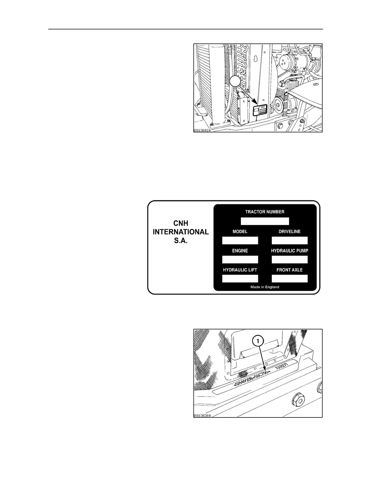
Tractor identification data must be supplied to the
dealer when requesting parts or service and will also
1
be needed to aid in identifying the tractor if it is ever
stolen.
The following provides the locations of the
identification data.
1
Vehicle Identification Plate
The vehicle identification plate,
(1) Figure
1 is
located on the left-hand radiator support. Record the
information on the sample identification plate
provided below.
2
Tractor Identification
The serial number and model identification
information is stamped on the top of the front support
(1). These numbers are also repeated on the vehicle
identification plate reproduced above.
3
1--3
SECTION 1 -- GENERAL INFORMATION AND SAFETY
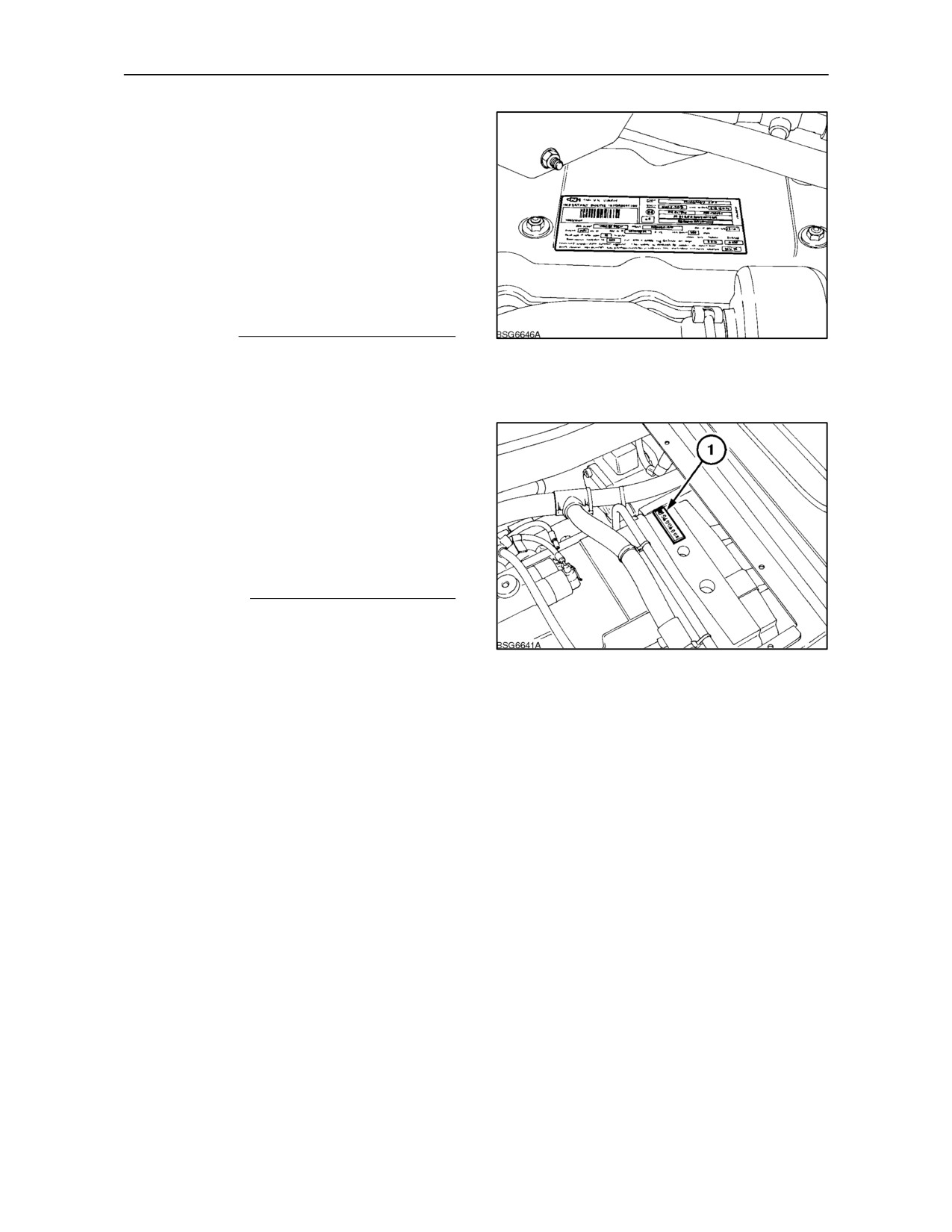
Engine Identification
The engine serial number and date code are
stamped on the engine identification plate.
The identification plate is located on top of the engine
attached to the valve cover. The plate also provides
information on engine adjustments and compliance
with Emission Regulations where required.
Record the information below for quick reference.
Engine Serial No.
4
Driveline Identification
The serial number plate (1) is located on top of the
transmission casing. Access to the number can be
gained by removing the plate in the floor of the cab
as shown in the illustration. This number is repeated
on the vehicle identification plate. Record the
information below for quick reference.
Driveline Serial No.
5
1--4
SECTION 1 -- GENERAL INFORMATION AND SAFETY
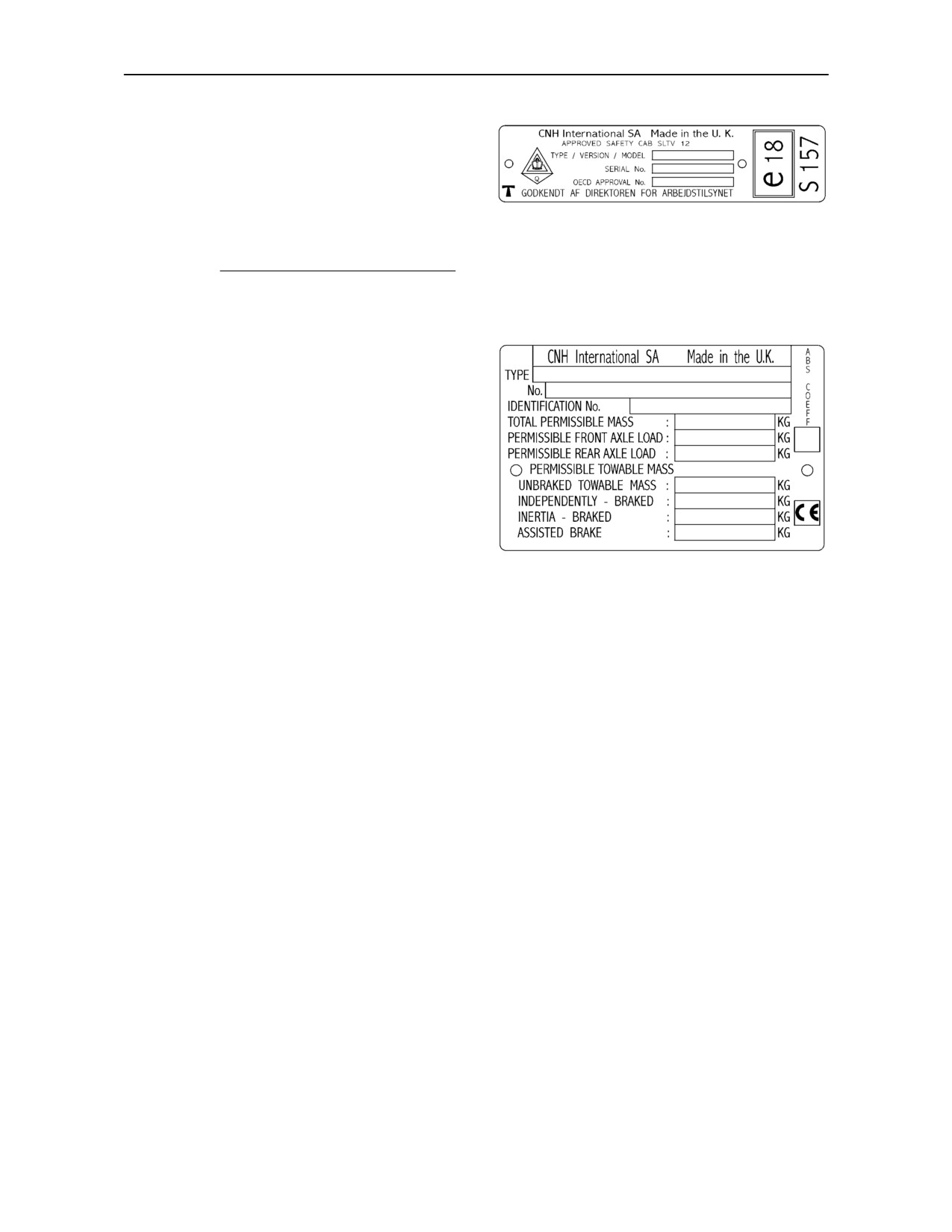
Cab Identification
The cab serial number and other information is on the
OECD certification plate. This plate can be found on
the right--hand side of the cab trim panel, below the
rear window. Record the cab serial number below for
6
quick reference.
Cab Serial No.
Vehicle Weight Information
The Vehicle Weighting Plate provides important
information on tractor and towed equipment weight
combinations. This plate can be found on the
right--hand side of the cab trim panel, below the rear
window.
The figures shown are the maximum permissible
weights and should not be exceeded, to do so may
affect the safe operation of the tractor.
7
1--5
SECTION 1 -- GENERAL INFORMATION AND SAFETY
ECOLOGY AND THE ENVIRONMENT
Soil, air and water are vital factors of agriculture and
4.
Avoid spillage when draining off used engine
life in general. Where legislation does not yet rule the
coolant mixtures, engine, gearbox and hydraulic
treatment of some of the substances which are
oils, brake fluids, etc. Do not mix drained brake
required by advanced technology, common sense
fluids or fuels with lubricants. Store them safely
should govern the use and disposal of products of a
until they can be disposed of in a proper way to
chemical and petrochemical nature.
comply with local legislation and available
resources.
The following are recommendations which may be of
assistance:
5.
Modern coolant mixtures, i.e. antifreeze and
other additives, should be replaced every two
• Become acquainted with and ensure that you
years. They should not be allowed to get into the
understand the relative legislation applicable to
soil but should be collected and disposed of
your country.
safely.
• Where no legislation exists, obtain information
6.
Do not open the air-conditioning system yourself.
from suppliers of oils, filters, batteries, fuels, anti
It contains gases which should not be released
freeze, cleaning agents, etc., with regard to their
into the atmosphere. Your dealer or air
effect on man and nature and how to safely store,
conditioning specialist has a special extractor for
use and dispose of these substances.
this purpose and will have to recharge the system
Agricultural consultants will, in many cases, be
anyway.
able to help you as well.
7.
Repair any leaks or defects in the engine cooling
HELPFUL HINTS
or hydraulic system immediately.
1. Avoid filling tanks using unsuitable containers or
8.
Do not increase the pressure in a pressurised
inappropriate pressurised fuel delivery systems
circuit as this may lead to the components
which may cause considerable spillage.
exploding.
2. In general, avoid skin contact with all fuels, oils,
9.
Protect hoses during welding as penetrating
acids, solvents, etc. Most of them contain
weld splatter may burn a hole or weaken them,
substances which can be harmful to your health.
causing the loss of oils, coolant, etc.
3. Modern oils contain additives. Do not burn
contaminated fuels and/or waste oils in ordinary
heating systems.
1--6
SECTION 1 -- GENERAL INFORMATION AND SAFETY
SAFETY PRECAUTIONS
A careful operator is the best operator. Most accidents
THE TRACTOR
can be avoided by observing certain precautions. To
help prevent accidents, read and take the following
1.
Read the Operator’s Manual carefully before
precautions before driving, operating or servicing the
using the tractor. Lack of operating knowledge
tractor. Equipment should be operated only by those
can lead to accidents.
who are responsible and instructed to do so.
2.
Only allow properly trained and qualified persons
PRECAUTIONARY STATEMENTS
to operate the tractor.
Throughout this Manual you will see text, preceded
3.
To prevent falls, use the handrails and step plates
by the words NOTE, ATTENTION, IMPORTANT,
when getting on and off the tractor. Keep steps
CAUTION, WARNING or DANGER. Such text has
and platform clear of mud and debris.
the following significance:
4.
Replace all missing, illegible or damaged safety
MACHINE SAFETY
decals.
NOTE: This text stresses a correct operating
5.
Keep safety decals free of dirt or grime.
technique or procedure.
ATTENTION: This text warns the operator of potential
machine damage if a certain procedure is not followed.
IMPORTANT: This text informs the reader of
something that he needs to know to prevent minor
machine damage if a certain procedure is not
followed.
PERSONAL SAFETY
CAUTION
The word CAUTION is used where a safe
behavioural practice, according to operating and
maintenance instructions and common safety
6.
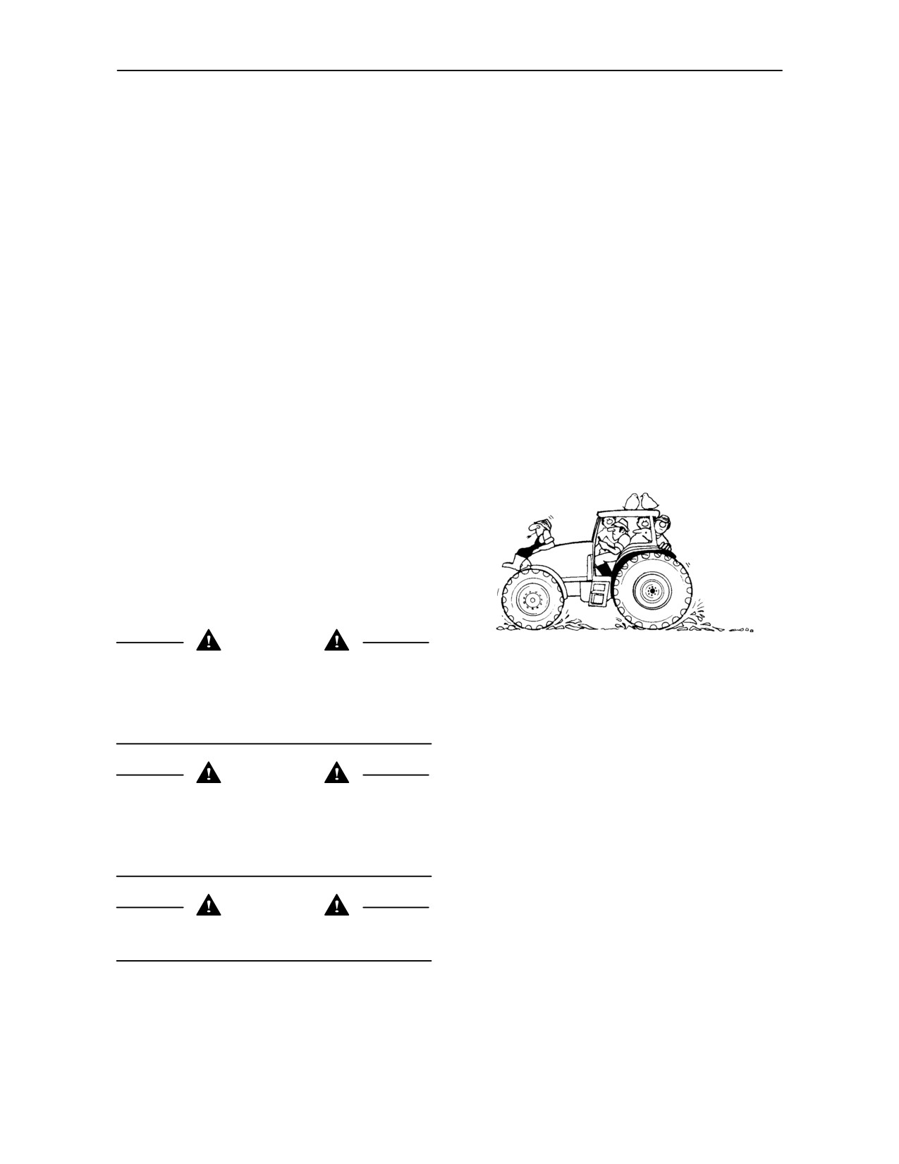
Do not permit anyone but the operator to ride on
practices will protect the operator and others from
the tractor except for driver training or instruction.
accident involvement.
When used for these purposes an additional seat
may be fitted in the cab. Passengers should not
be carried on the tractor at any time.
WARNING
The word WARNING denotes a potential or hidden
7.
Keep children away from the tractor and farm
hazard which could possibly cause serious injury. It
machinery at all times.
is used to warn operators and others to exercise due
care and attention to avoid a surprise accident with
8.
Do not modify or alter or permit anyone else to
machinery.
modify or alter the tractor or any of its
components or any tractor function without first
consulting your dealer.
DANGER
The word DANGER denotes a forbidden practice in
9.
Install all guards before starting the engine or
connection with a serious hazard.
operating the tractor.
Failure to follow the CAUTION, WARNING and
DANGER instructions may result in serious bodily
injury or even death.
1--7
SECTION 1 -- GENERAL INFORMATION AND SAFETY
DRIVING THE TRACTOR
1.
Always sit in the driver’s seat while starting or
driving the tractor.
2.
When driving on public roads, have
consideration for other road users. Pull in to the
side of the road occasionally to allow any
following traffic to pass. Do not exceed the legal
speed limit set in your country for agricultural
tractors.
3.
Use a rotating beacon and/or Slow Moving
Vehicle warning when driving on public roads to
indicate that the vehicle is slow moving and is a
8.
Keep the tractor in the same gear when going
possible hazard.
downhill as would be used when going uphill. Do
not coast or freewheel down hills.
4.
Dip the tractor lights when meeting a vehicle at
9.
For safe operation any towed vehicle whose total
night. Make sure the lights are adjusted to
weight exceeds that of the towing tractor must be
prevent blinding the driver of an oncoming
equipped with a braking system that complies
vehicle.
with the legal requirements of that country.
5.
Reduce speed before turning or applying the
10. Never apply the differential lock when turning.
brakes. Brake both wheels simultaneously when
When engaged, the differential lock will prevent
making an emergency stop. Ensure that both
the tractor from turning.
brake pedals are locked together when travelling
at road speeds or when on public roads to ensure
11. Always check overhead clearance, especially
correct operation of trailer brakes, balanced
when transporting the tractor. Watch where you
operation of the tractor brakes and four wheel
are going, especially at row ends, on roads and
braking (4WD tractors only).
around trees and low overhanging obstacles.
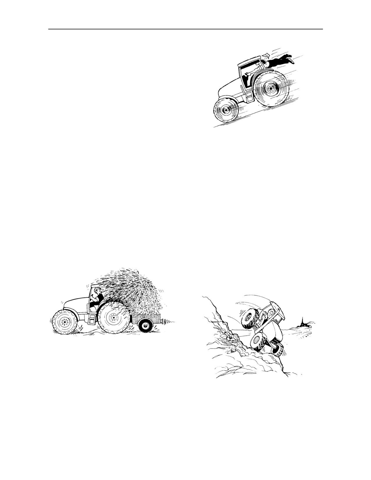
12. To avoid overturns, drive the tractor with care and
at speeds compatible with safety, especially
when operating over rough ground, when
crossing ditches or slopes and when turning
corners.
6. On four wheel drive tractors, the drive to the front
axle is automatically engaged, to provide four
wheel braking, when both footbrakes are
applied. Owners should be aware of the
effectiveness of four wheel braking which greatly
13. Use extreme caution when operating on steep
enhances braking performance. Appropriate
slopes.
care should be exercised during fierce braking.
14. If the tractor becomes stuck or the tyres are
7. Use extreme caution and avoid hard application
frozen to the ground, reverse the tractor out to
of the tractor brakes when towing heavy loads at
prevent overturning.
road speeds.
1--8
SECTION 1 -- GENERAL INFORMATION AND SAFETY
OPERATING THE TRACTOR
1. Apply the parking brake, place the P.T.O. control
in the ‘OFF’ position, the lift control lever in the
down position, the remote control valve levers in
the neutral position and the transmission levers
in neutral before starting the tractor.
2. Do not start the engine or operate controls (other
than externally located hydraulic lift or P.T.O.
switches, if fitted) while standing beside the
tractor. Always sit in the tractor seat when
starting the engine or operating the controls.
3. Do not bypass the transmission and P.T.O.
8.
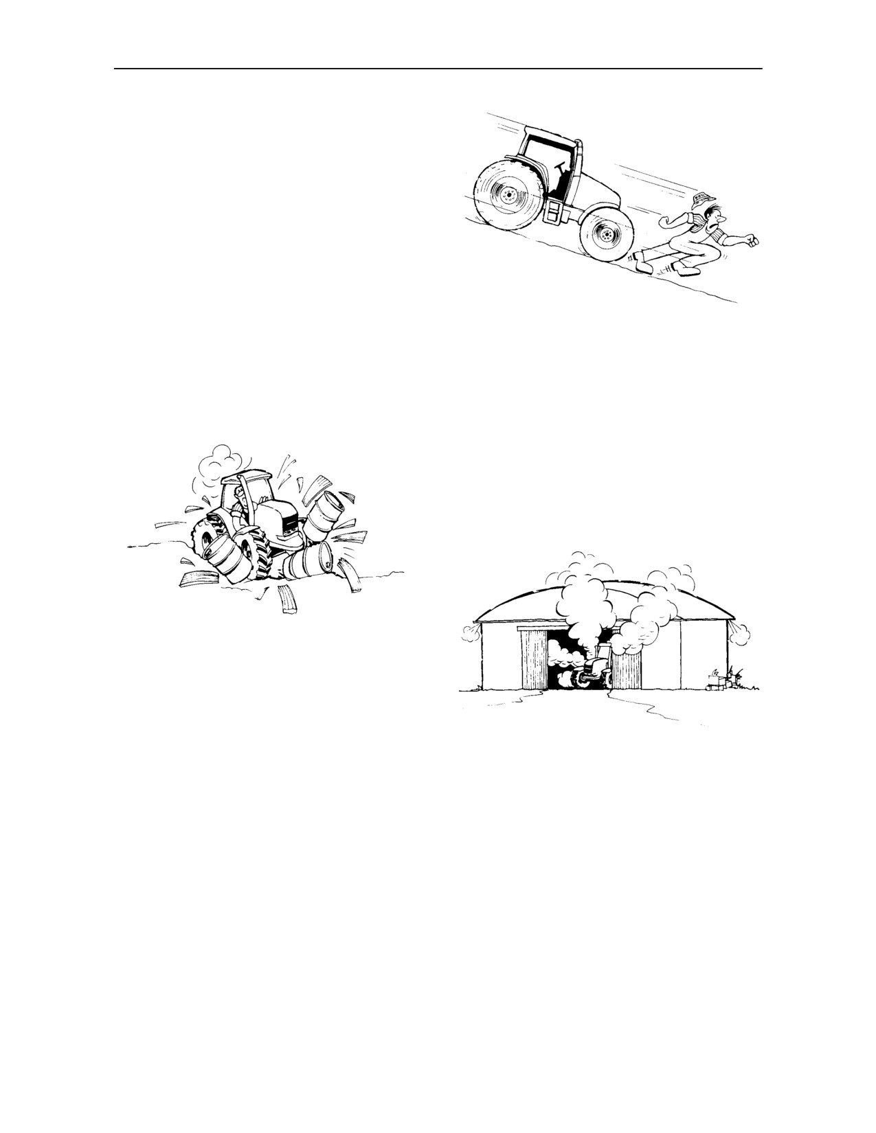
Do not park the tractor on a steep incline.
neutral start switches. Consult your authorised
dealer if your neutral start controls malfunction.
9.
The cab is designed to provide the minimum
Use jump leads only in the recommended
noise level at the operator’s ears and meets or
manner. Improper use can result in a tractor
exceeds applicable standards in this respect.
runaway.
However, noise (sound pressure level) in the
workplace can exceed 85 dB(A) when working
between buildings or in confined spaces, with
cab windows open. Therefore, it is
recommended that operators wear suitable ear
protectors when operating in high noise level
conditions.
4. Avoid accidental contact with the gear shift levers
while the engine is running. Unexpected tractor
movement can result from such contact.
5. Do not get off the tractor while it is in motion.
6. If the power steering or engine ceases operating,
10. Do not run the tractor engine in an enclosed
stop the tractor immediately as the tractor will be
building without adequate ventilation. Exhaust
more difficult to control.
fumes are toxic and can cause death.
7. Before leaving the tractor, park the tractor on
11. Pull only from the pick-up hitch, swinging
level ground, apply the parking brake, lower
drawbar or the lower link drawbar in the lowered
attached implements to the ground, disengage
position. Use only a drawbar pin that locks in
the P.T.O. and stop the engine.
place. Pulling from the tractor rear axle or any
point above the axle may cause the tractor to
overturn.
1--9
SECTION 1 -- GENERAL INFORMATION AND SAFETY
12. Always select Position Control when attaching
OPERATING THE P.T.O.
equipment and when transporting equipment. Be
sure hydraulic couplers are properly mounted
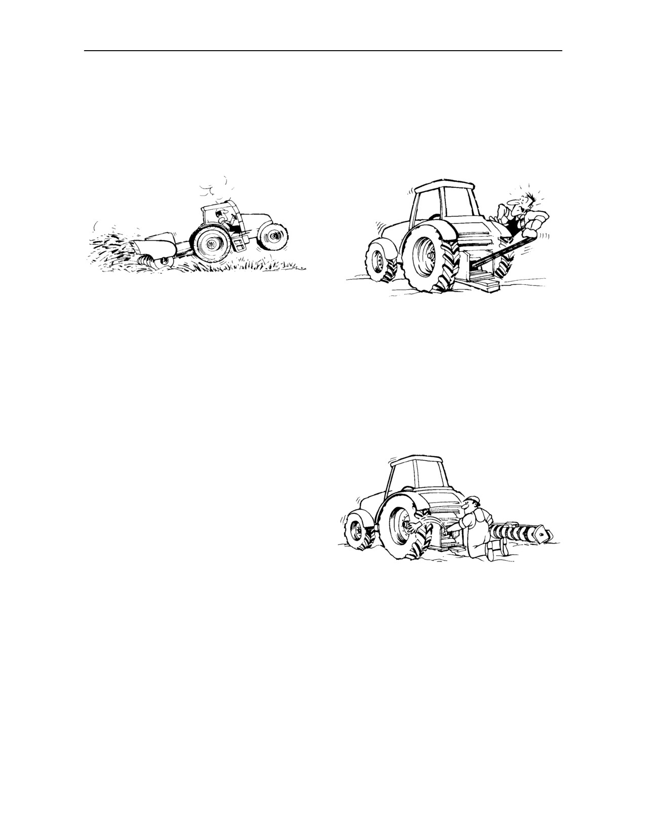
1. When operating P.T.O.- driven equipment, shut
and will disconnect safely in case of accidental
off the engine, switch off the P.T.O. and wait until
detachment of the implement.
the P.T.O. stops before getting off the tractor and
disconnecting the equipment.
13. If the front end of the tractor tends to rise when
heavy implements are attached to the
2.
Do not wear loose clothing when operating the
three--point hitch, install front end or front wheel
power take-off or especially when near rotating
weights. Do not operate the tractor with a light
equipment.
front end.
3.
When operating stationary P.T.O.-driven
14. Engage the clutch slowly when driving out of a
equipment, always apply the tractor parking
ditch, gully or up a steep hillside. Disengage the
brake and block the rear wheels front and back.
clutch promptly if the front wheels rise off the
ground.
15. Ensure any attached equipment or accessories
are correctly installed, are approved for use with
the tractor, do not overload the tractor and are
operated and maintained in accordance with the
instructions issued by the equipment or
accessory manufacturer.
16. Remember that your tractor, if abused or
incorrectly used, can be dangerous and become
a hazard both to the operator and to bystanders.
Do not overload or operate with attached
equipment which is unsafe, not designed for the
particular task or is poorly maintained.
4.
To avoid injury, do not clean, adjust, unclog or
17. Do not leave equipment in the raised position
service P.T.O. driven equipment when the tractor
when the vehicle is stopped or unattended.
engine is running. Ensure that the P.T.O. is
switched off.
18. Do not drive equipment near open fires.
5.
Make sure the P.T.O. guard is in position at all
times and always replace the P.T.O. cap when
19. Always wear a protective mask when working
the P.T.O. is not in use.
with toxic spray chemicals. Follow the directions
on the chemical container.
1--10
SECTION 1 -- GENERAL INFORMATION AND SAFETY
SERVICING THE TRACTOR
Unqualified persons should not remove or
attempt to adjust a pump, injector, nozzle or any
other part of the fuel injection or hydraulic
systems. Failure to follow these instructions can
result in serious injury.
• Do not use your hand to check for leaks. Use a
piece of cardboard or paper to search for leaks.
• Stop the engine and relieve pressure before
connecting or disconnecting lines.
1.
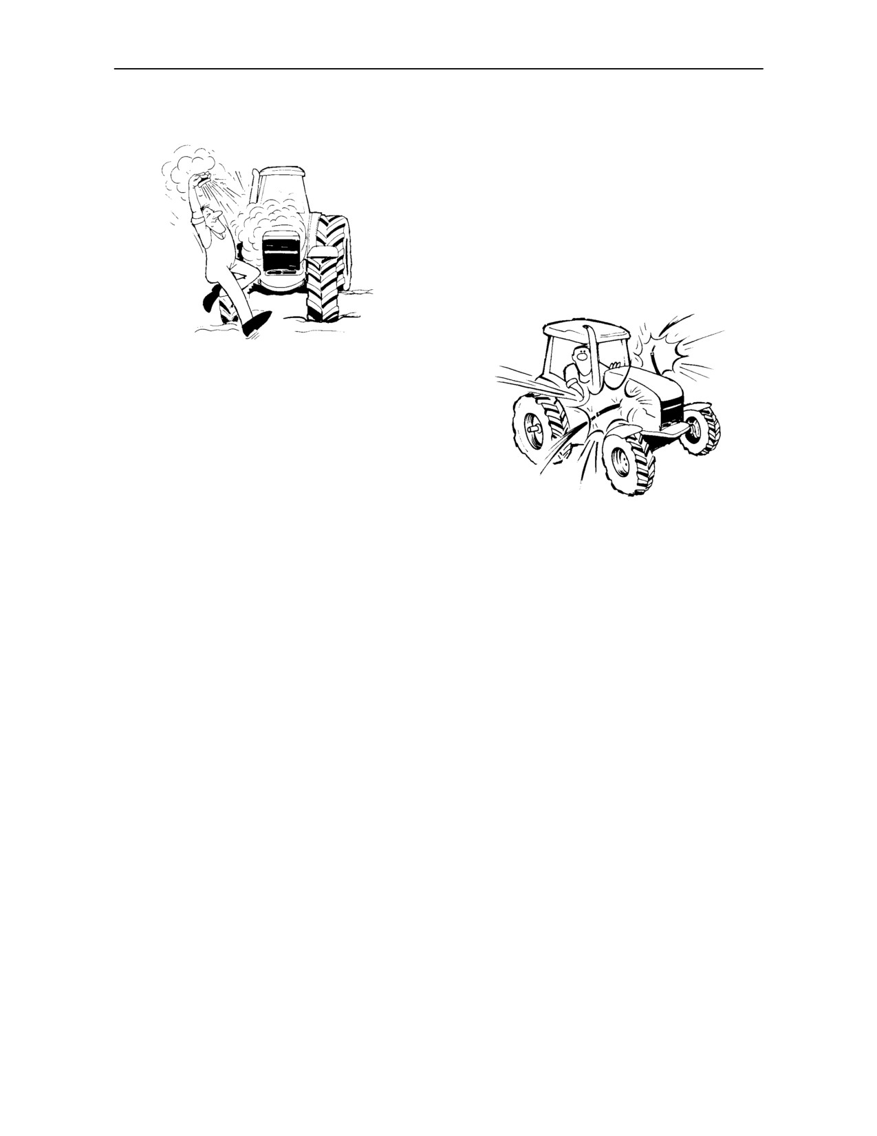
The cooling system operates under pressure
which is controlled by the expansion tank cap. It
is dangerous to remove the cap while the system
is hot. Always turn the cap slowly to the first stop
and allow the pressure to escape before
removing the cap entirely. Never remove the cap
from the top of the radiator unless the expansion
tank pressure cap has first been removed.
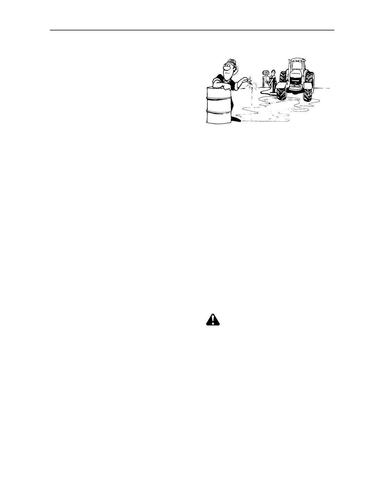
2.
Do not smoke while refuelling the tractor. Keep
any type of open flame away.
•
Tighten all connections before starting the
engine or pressurising lines.
3.
Keep the tractor and equipment, particularly
brakes and steering, maintained in a reliable and
•
If fluid is injected into the skin obtain medical
satisfactory condition to ensure your safety and
attention immediately or gangrene may result.
comply with legal requirements.
8.
Do not modify or alter or permit anyone else to
4.
To prevent fire or explosion, keep open flames
modify or alter the tractor or any of its
away from battery or cold weather starting aids.
components or any tractor function without first
To prevent sparks which could cause explosion,
consulting an authorised dealer.
use jumper cables according to instructions.
9.
Continuous long term contact with used engine
5.
Do not attempt to service the air conditioning
oil may cause skin cancer. Avoid prolonged
system. It is possible to be severely frost bitten or
contact with used engine oil. Wash skin promptly
injured by escaping refrigerant. Special
with soap and water.
equipment and instruments are required to
service the air conditioning system. See your
10. Keep equipment clean and properly maintained.
authorised dealer for service.
11. Dispose of all drained fluids and removed filters
6.
Stop the engine before performing any service
properly.
on the tractor.
12. Tractor wheels are very heavy. Handle with care
7.
Hydraulic fluid and fuel oil in the injection system
and ensure, when stored, that they cannot topple
operate under high pressure. Escaping hydraulic
and cause injury.
fluid or fuel oil under pressure can penetrate the
skin causing serious injury.
1--11
SECTION 1 -- GENERAL INFORMATION AND SAFETY
DIESEL FUEL
1.
Under no circumstances should gasoline,
alcohol or blended fuels be added to diesel fuel.
These combinations can create an increased fire
or explosive hazard. In a closed container such
as a fuel tank these blends are more explosive
than pure gasoline. Do not use these blends.
2.
Never remove the fuel cap or refuel with the
engine running or hot.
3.
Do not smoke while refuelling the tractor or when
standing near fuel. Keep any type of open flame
away.
4.
Maintain control of the fuel filler pipe nozzle when
filling the tank.
5.
Do not fill the fuel tank to capacity. Fill only to the
bottom of the filler neck to allow room for
expansion.
6.
Wipe up spilled fuel immediately.
7.
Always tighten the fuel tank cap securely.
8.
If the original fuel tank cap is lost, replace it with
an approved cap. A non--approved cap may not
be safe.
9.
Never use fuel for cleaning purposes.
10. Arrange fuel purchases so that summer grade
fuels are not held over and used in the winter.
WHENEVER YOU SEE THIS SYMBOL
IT MEANS: ATTENTION!
BECOME ALERT! YOUR SAFETY IS INVOLVED!
1--12
SECTION 1 -- GENERAL INFORMATION AND SAFETY
OPERATOR PROTECTIVE STRUCTURE
WARNING
Your machine is equipped with an operator
Protective Structure, such as: a Roll Over Protective
Structure
(ROPS) or Falling Object Protective
Structure (FOPS) or Cab with ROPS. A ROPS may
be a cab frame or a two--posted or four--posted
structure used for the protection of the operator to
minimise the possibility of serious injury.
The Protective Structure is a special safety
component of your machine.
DO NOT attach any device to the Protective
Structure for pulling purposes. DO NOT drill holes to
the Protective Structure.
The Protective Structure and interconnecting
components are a certified system. Any damage,
fire, corrosion or modification will weaken the
structure and reduce your protection. If this occurs,
the Protective Structure MUST be replaced so that
it will provide the same protection as a new Protective
Structure. Contact your dealer for Protective
Structure inspection and replacement.
After an accident, fire, tip or roll over, the following
MUST be performed by a qualified technician before
returning the machine to field or job site operation.
• The Protective Structure MUST be replaced.
• The mounting or suspension for the Protective
Structure, operator seat and suspension, seat
belts and mounting components and wiring
within the operator’s protective system MUST be
carefully inspected for damage.
• All damaged parts MUST be replaced.
DO NOT WELD, DRILL HOLES, ATTEMPT TO
STRAIGHTEN OR REPAIR THE PROTECTIVE
STRUCTURE. MODIFICATION IN ANY WAY CAN
REDUCETHESTRUCTURALINTEGRITY OFTHE
STRUCTURE WHICH COULD CAUSE DEATH OR
SERIOUS INJURY IN THE EVENT OF FIRE, TIP,
ROLL OVER, COLLISION OR ACCIDENT.
1--13
SECTION 1 -- GENERAL INFORMATION AND SAFETY
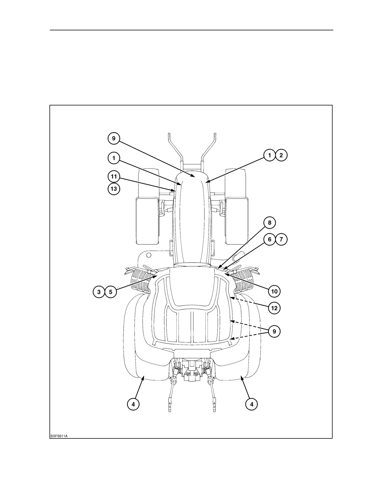
SAFETY DECALS
The decals reproduced on the following pages were installed on your tractor in the positions indicated in the drawings
below. They are intended for your safety and for those working with you. Please take this Manual and walk around
your tractor, noting the location of the decals and their significance. Review the decals and operating instructions
detailed in this Manual with the machine operators. Keep the decals clean and legible. If they become damaged or
illegible, obtain replacements from your authorised dealer.
1--14
SECTION 1 -- GENERAL INFORMATION AND SAFETY
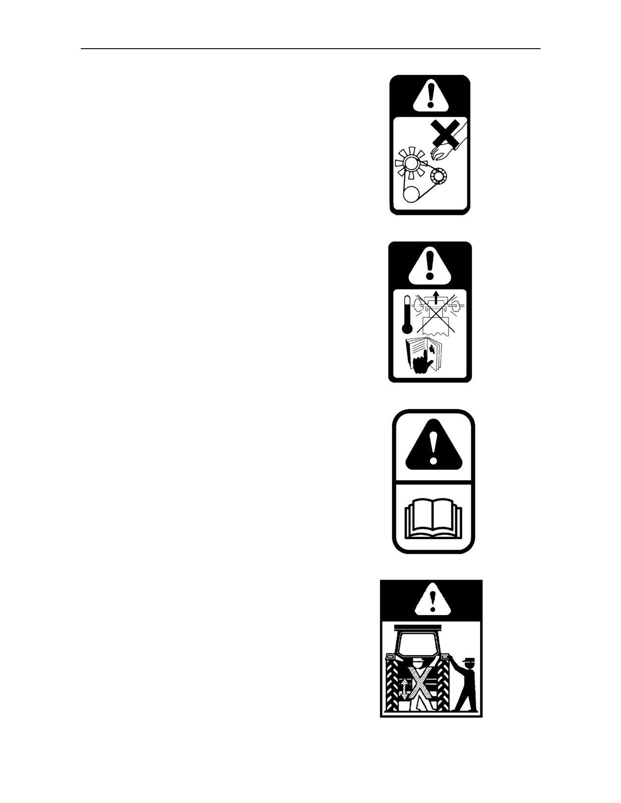
1. Location:
Left and right-hand side of fan guard
To prevent serious injury, keep hands and clothing
away from rotating fan and drive belt.
Part No. 81871830
2. Location:
Right--hand side of radiator
Warning! Pressurised cooling system. Allow to cool
then remove cap carefully. Using a cloth, turn cap to
the first stop and allow pressure to subside before
removing cap completely.
Part No. 5194556
3. Location:
Left--hand ’A’ pillar, inside cab
General warning. Read and understand all the
warning notes printed in this Operator’s Manual. In
particular, see pages 1--7 to 1--13 inclusive.
Part No. 82001826
4. Location:
Rear of both fenders (with external power
controls only)
To avoid injury, do not stand on the implement or
between the implement and tractor while operating
the external lift or P.T.O. controls.
Part No. 83982553
1--15
SECTION 1 -- GENERAL INFORMATION AND SAFETY
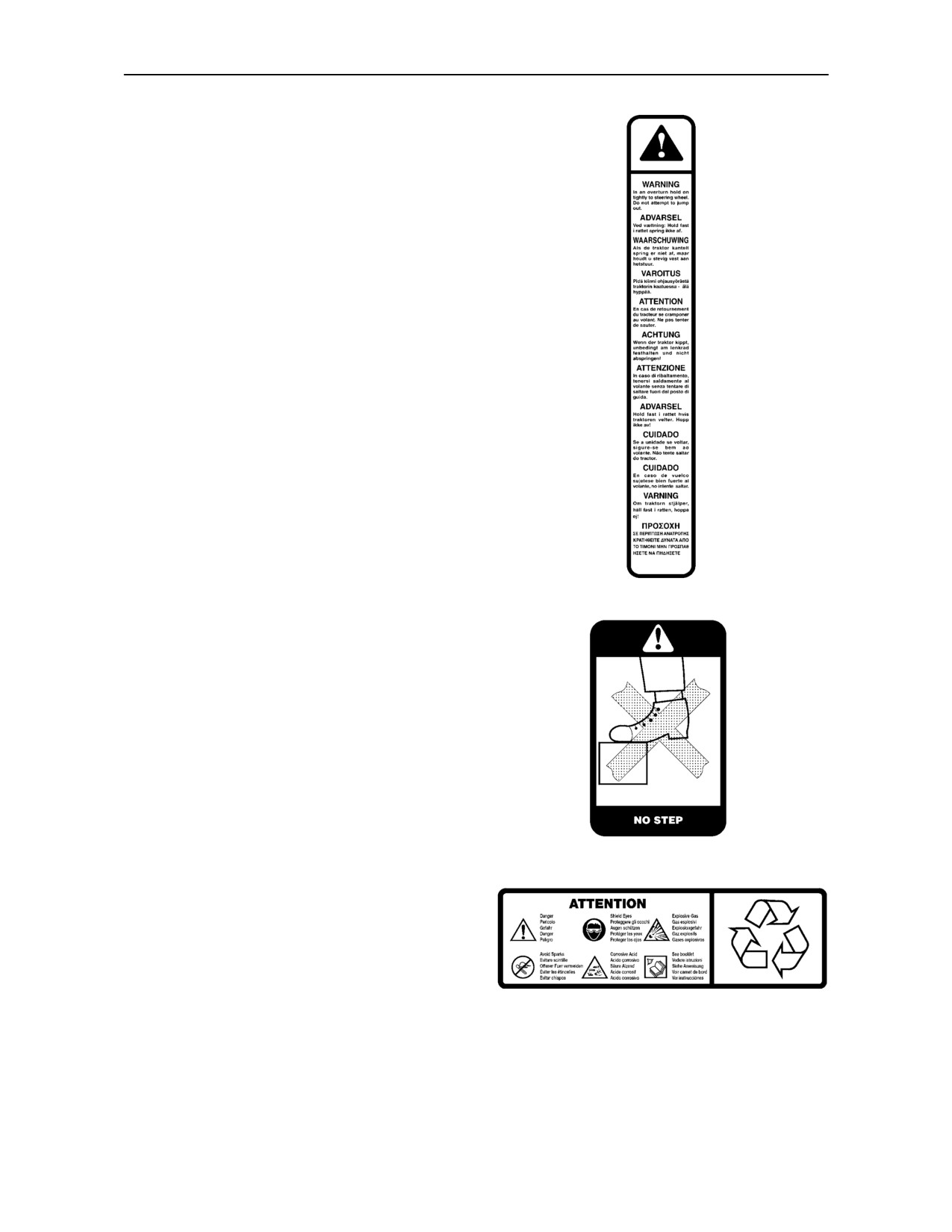
5. Location:
Left--hand ‘A’ pillar inside the cab
In an overturn, hold on tightly to the steering wheel.
Do not attempt to jump out.
Part No. 82016113
6. Location:
Top of toolbox
Do not stand on toolbox.
Part No. 82010947
7. Location:
Top of battery
Danger! Corrosive acid. Explosive gas. Wear eye
protection. Avoid producing sparks. See Operator’s
Manual.
1--16
SECTION 1 -- GENERAL INFORMATION AND SAFETY
8. Location:
Radar sensor mounting bracket
To avoid possible eye damage from micro-wave
signals emitted by the radar sensor, do not look
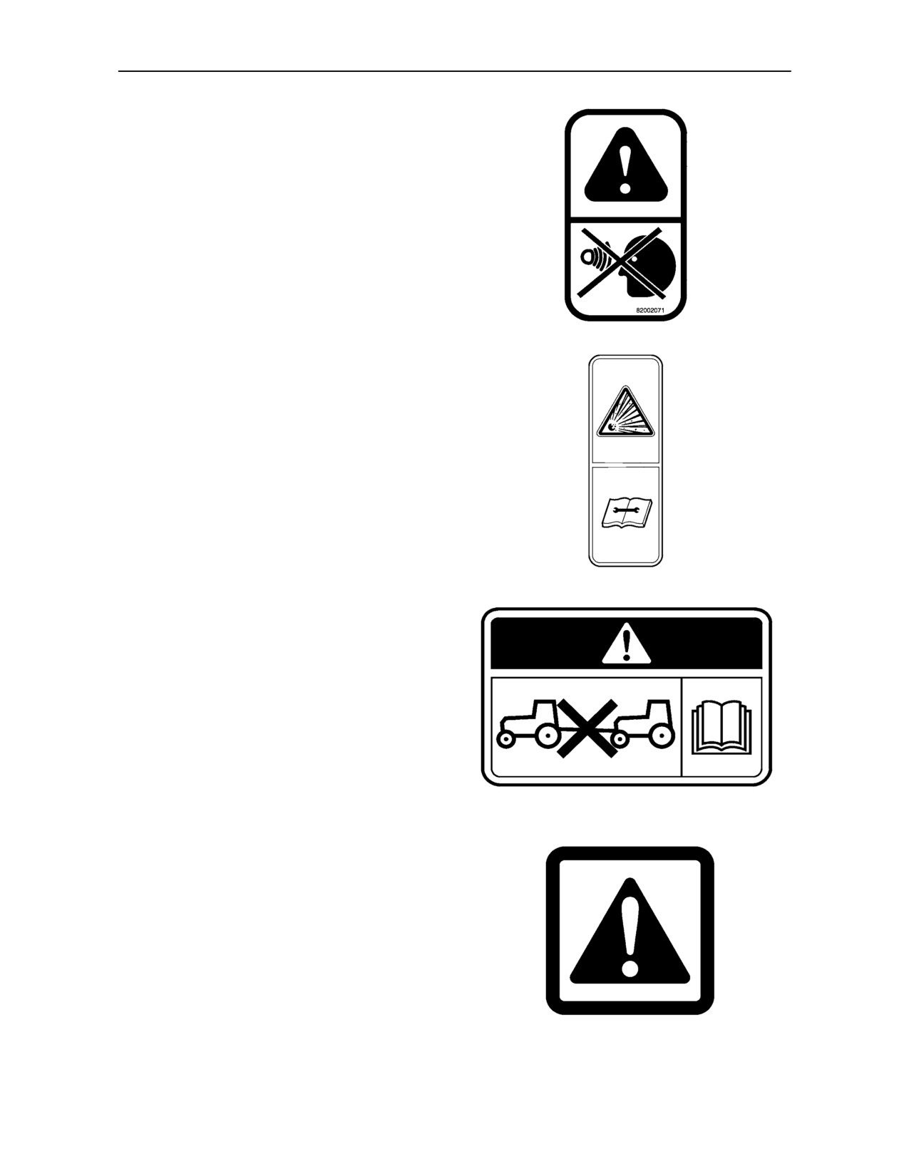
directly into the sensor face.
Part No. 82002071
9. Location:
Hydraulic Accumulator/s
Caution! High pressure hydraulic/gas accumulator.
Follow service manual instructions for removal or
repair.
Part No. 82029751
10.Location:
Location: Right--hand ’A’ pillar inside cab
Caution! Read Operator’s Manual. before attempting
to tow.
Part No. 82030522
11.Location:
Air conditioning compressor
Warning! Fluid under pressure, do not disconnect
any lines. Read Operator’s Manual.
Part No. 83946774
1--17
SECTION 1 -- GENERAL INFORMATION AND SAFETY
12.Location:
Right--hand control console
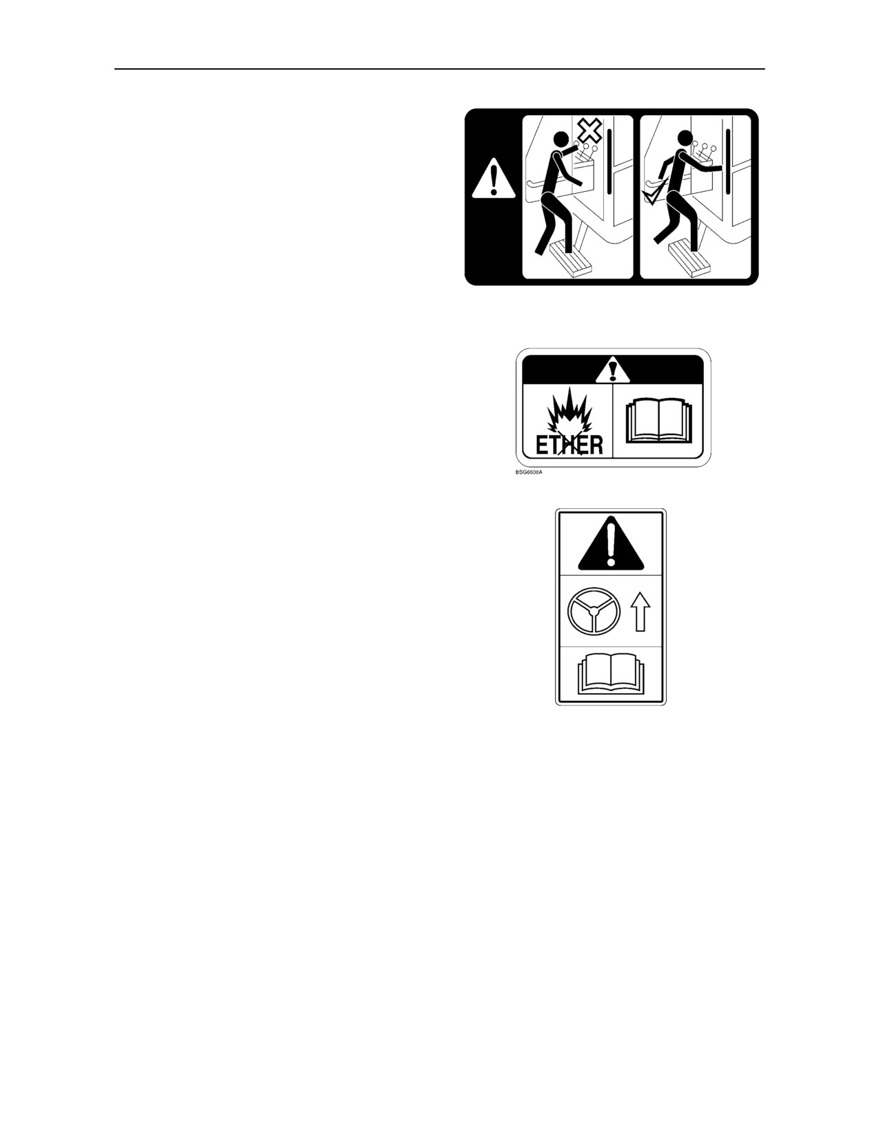
Caution! Always use grab handles when entering or
leaving the platform/cab.
Part No. 81871702
13.Location:
Left--hand side of radiator
Warning! Heater Grid cold start aid. Do not use ether
or risk of explosion will occur.
Part No. 87802167
14.Location:
Right--hand ’A’ pillar inside cab
Warning! De--activate Fast Steer system before
travelling on the highway. Read Operator’s Manual.
Part No. 87331567
1--18

SECTION 1 -- GENERAL INFORMATION AND SAFETY
INTERNATIONAL SYMBOLS
As a guide to the operation of your tractor, various universal symbols have been utilised on the instruments,
controls, switches, and fuse box. The symbols are shown below with an indication of their meaning.
Thermostart
Radio
P.T.O.
Position
starting aid
Control
Keep alive
Draft
Alternator
memory
N
Transmission
Control
KAM
charge
in neutral
Accessory
Turn signals
Creeper
socket
Fuel level
gears
Implement
Turn signals
Automatic
Slow or
socket
--one trailer
Fuel shut-off
low setting
%age
Turn signals
slip
Engine speed
--two trailers
Fast or high
(rev/min x 100)
setting
Front wind-
Hitch raise
screen
(rear)
Ground
Hours recorded
wash/wipe
speed
Hitch lower
Rear wind-
(rear)
Engine oil
screen
Differential
pressure
wash/wipe
lock
Hitch height
limit (rear)
Heater temp-
Rear axle
Engine coolant
erature control
oil tem-
temperature
perature
Hitch height
limit (front)
Heater fan
Coolant
Transmission
level
oil pressure
Hitch dis-
abled
Air conditioner
FWD
Tractor lights
Hydraulic and
engaged
Air filter
transmission
blocked
filters
Headlamp
FWD dis-
main beam
Parking
engaged
Remote
brake
valve extend
Headlamp
Brake fluid
Remote
Warning!
dipped beam
level
valve retract
Trailer
Hazard
Remote
Work lamps
brake
warning lights
valve float
Malfunction!
Stop
Roof
Variable
See Operator’s
lamps
beacon
control
Manual
Warning!
Pressurised!
Malfunction! (alter-
Horn
Corrosive
Open carefully
native symbol)
substance
1--19
SECTION 1 -- GENERAL INFORMATION AND SAFETY
AIRBORNE NOISE EMISSION
In accordance with E.E.C. directives, the noise levels of tractors covered by this manual are as follows:
Tractors with Cabin and Fixed Windscreen
with Air Cleaner Extraction System
Noise level at operators ear
Drive by noise level
Closed(1)
Open(2)
Model Transmission
Annex II*
Annex II*
Annex IV**
T6010
All Transmissions
70.0 dB(A)
75.0 dB(A)
80.0 dB(A)
T6020
All Transmissions
70.0 dB(A)
75.0 dB(A)
80.0 dB(A)
T6030
All Transmissions
73.0 dB(A)
79.0 dB(A)
84.0 dB(A)
T6050
All Transmissions
73.0 dB(A)
79.0 dB(A)
84.0 dB(A)
T6070
All Transmissions
73.0 dB(A)
79.0 dB(A)
84.0 dB(A)
Tractors with ROPS and Canopy
with Air Cleaner Extraction System
Noise level at operators ear
Drive by noise level
Closed(1)
Open(2)
Model Transmission
Annex II*
Annex II*
Annex IV**
T6010
All Transmissions
n/a
85.0 dB(A)
80.0 dB(A)
T6020
All Transmissions
n/a
85.0 dB(A)
80.0 dB(A)
T6030
All Transmissions
n/a
85.0 dB(A)
84.0 dB(A)
T6050
All Transmissions
n/a
85.0 dB(A)
84.0 dB(A)
* Test results are in accordance with directive 77/311/EEC Annex II.
Maximum noise level at the operators ear with:
1) all cab windows and doors closed, tractor off load
2) rear window and roof hatch open, tractor off load.
** Test results are in accordance with directive 74/151/EEC Annex VI.
1--20
SECTION 1 -- GENERAL INFORMATION AND SAFETY
In accordance with E.E.C. directives, the noise levels of tractors covered by this manual are as follows:
Tractors with Cabin and Fixed Windscreen
without Air Cleaner Extraction System
Noise level at operators ear
Drive by noise level
Closed(1)
Open(2)
Model Transmission
Annex II*
Annex II*
Annex IV**
T6010
All Transmissions
72.0 dB(A)
77.0 dB(A)
81.0 dB(A)
T6020
All Transmissions
72.0 dB(A)
77.0 dB(A)
81.0 dB(A)
T6030
All Transmissions
73.0 dB(A)
79.0 dB(A)
84.0 dB(A)
T6050
All Transmissions
73.0 dB(A)
79.0 dB(A)
84.0 dB(A)
T6070
All Transmissions
73.0 dB(A)
79.0 dB(A)
84.0 dB(A)
Tractors with ROPS and Canopy
without Air Cleaner Extraction System
Noise level at operators ear
Drive by noise level
Closed(1)
Open(2)
Model Transmission
Annex II*
Annex II*
Annex IV**
T6010
All Transmissions
n/a
86.0 dB(A)
81.0 dB(A)
T6020
All Transmissions
n/a
86.0 dB(A)
81.0 dB(A)
T6030
All Transmissions
n/a
85.0 dB(A)
84.0 dB(A)
T6050
All Transmissions
n/a
85.0 dB(A)
84.0 dB(A)
* Test results are in accordance with directive 77/311/EEC Annex II.
Maximum noise level at the operators ear with:
1) all cab windows and doors closed, tractor off load
2) rear window and roof hatch open, tractor off load.
** Test results are in accordance with directive 74/151/EEC Annex VI.
1--21
SECTION 2
CONTROLS, INSTRUMENTS AND OPERATION
BEFORE OPERATING
PROGRAMMING TRACTOR FUNCTIONS
CAUTION
Your tractor utilises two memory facilities to control
and memorise settings for the various electronic
Before driving or operating the tractor, study the
functions. The operating memory temporarily stores
safety precautions in Section 1 of this Manual.
setting adjustments made while operating the tractor
and these are uploaded to the main memory when
you key--off (engine stop).
Read this section thoroughly. It details the location
and operation of the various instruments, switches
and controls on your tractor. Even if you operate
If you key--off and key--on again too quickly as data
other tractors, you should thoroughly read this
is being uploaded, some of it may be lost or
section of the manual and ensure that you are
corrupted.
familiar with the location and function of all the
features of the tractor.
If you have made changes to any memorised
settings while operating the tractor, pause for five
Do not start the engine or attempt to drive or operate
seconds between key--off and key--on to allow the
the tractor until you are fully accustomed with all the
data to upload from the operating memory to the
controls. It is too late to learn once the tractor is
main memory. Once uploaded, the new settings will
moving. If in doubt about any aspect of operation of
remain unchanged until they are re--programmed.
the tractor, consult your authorised dealer.
Subject
Page
Pay particular attention to the recommendations for
running-in to ensure that your tractor will give the
Cab
2--7
long and dependable service for which it was
designed.
Seats
2--25
This section is split into various subjects, as follows.
Handbrake, Throttle and Foot Controls
2--32
Where a feature requires setting up and running
adjustments in the field, detailed instructions will be
Instrument Console
2--34
found in Section 3, Field Operation. Instructions for
the operation of various optional accessories will be
Analogue/Digital Instruments
2--37
found in Section 7.
Transmission Operation
2--65
Lubrication and maintenance requirements will be
found in Section 4. Tractor specifications are listed in
Section 8.
Synchro Command Transmission
(12 x 12)
2--67
A comprehensive index is provided at the end of this
book.
Dual Command Transmission
(24 x 24)
2--73
Electro Command Transmission
(16 x 16 and 17 x 16)
2--84
Differential Lock and Four Wheel Drive
2--102
Front Axle Suspension
2--106
2--1
SECTION 2 -- CONTROLS, INSTRUMENTS AND OPERATION
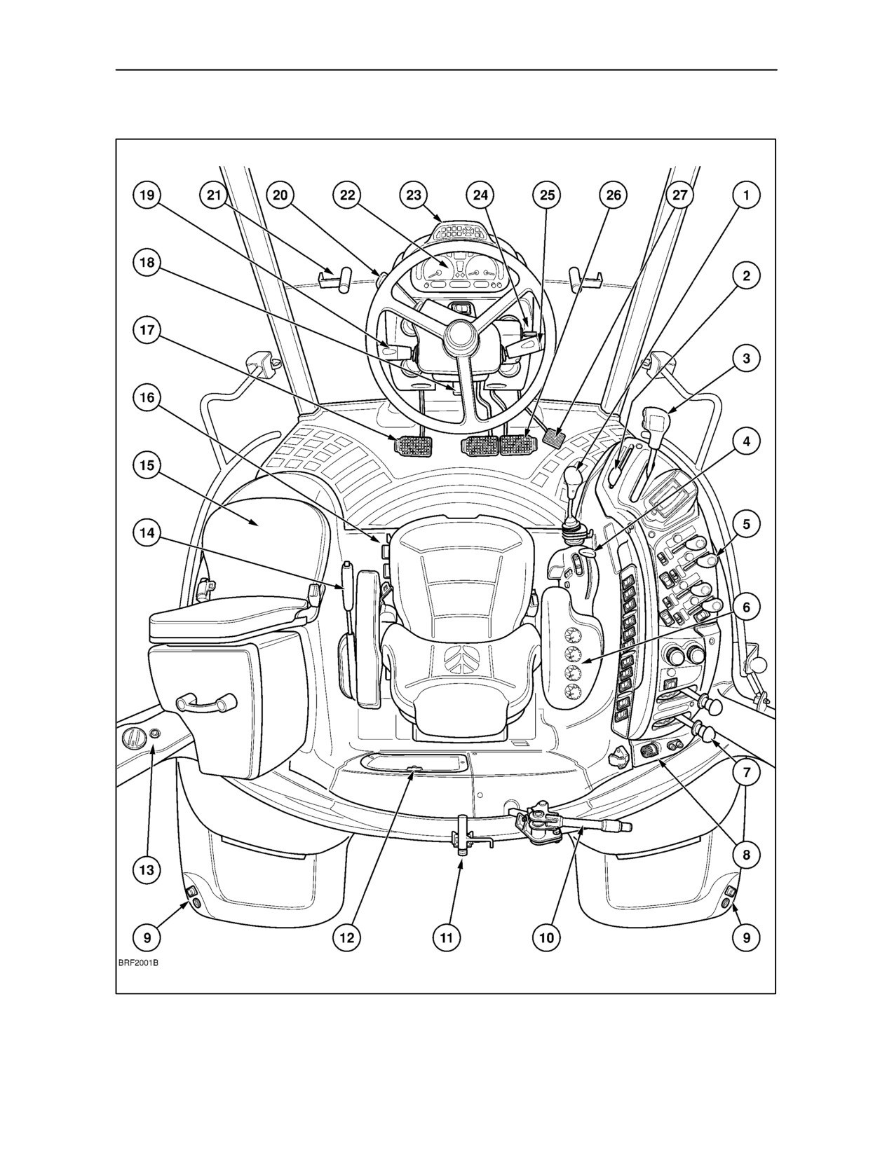
CAB AND PLATFORM CONTROLS
1
General View of Tractor Controls -- With Cab
2--2
SECTION 2 -- CONTROLS, INSTRUMENTS AND OPERATION
Key to Figure 1
Page Nos. for Reference
1.
Joystick control
3--34, 3--60
2.
Hand throttle
2--33
3.
Transmission controls
12x12 Synchro Command transmission
2--67
24x24 Dual Command transmission
2--73
16x16 (17x16) Electro Command transmission
2--84
4.
Hydraulics controls
Mechanical Lower Link sensing
3--41
Electronic Draft Control
3--47
5.
Remote control valve levers
Manual operation
3--59
Elecro--Hydraulic operation
3--69
6.
EDC panel
3--48
7.
P.T.O. controls
Front
3--33
Rear
3--14
8.
Electrical power panel
2--21
9.
External controls (where fitted)
3--point hitch
3--46, 3--57
Rear P.T.O
3--31
10. Release handle
Automatic pick--up hitch
3--108
Tow hitch
3--105
11. Rear window locking handle
2--10
12. Cab air recirculation filter
2--14
13. Cab climate controls (’C’ pillar)
2--13
14. Parking brake
2--32
15. Instructional seat
2--31
16. Seat controls
2--25
17. Clutch/inching pedal
2--32, 2--88
18. Steering column adjustment
2--34
19. Multi--function switch
2--35
20. Shuttle lever
2--68, 2--74, 2--86
21. Front window locking handle (where fitted)
2--10
22. Instrument panel
2--37
23. Enhanced keypad (where fitted)
2--56
24. Key--start switch
3--6
25. Wash/wipe control
2--36
26. Foot brakes
2--33
27. Foot throttle
2--32
2--3
SECTION 2 -- CONTROLS, INSTRUMENTS AND OPERATION
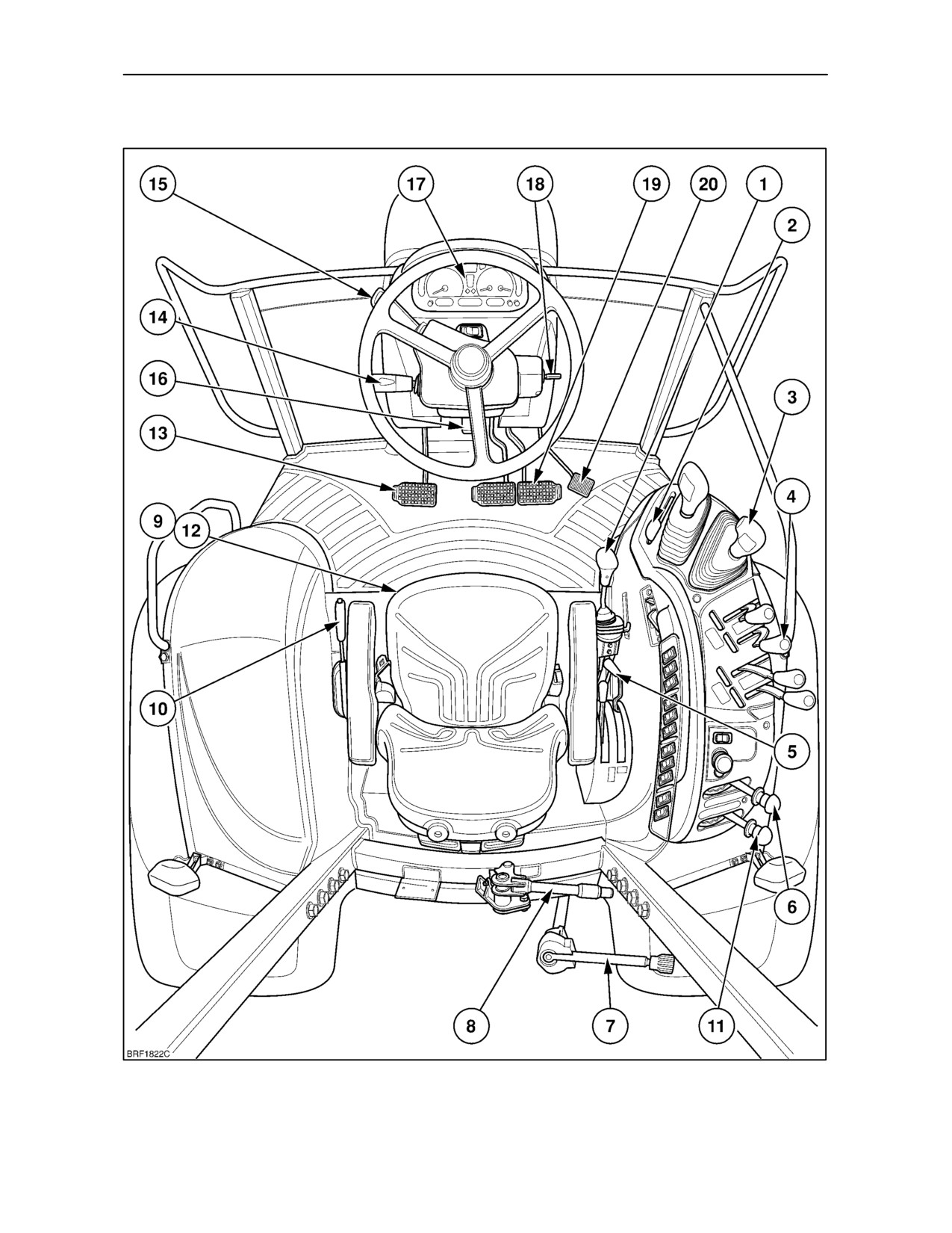
PLATFORM CONTROLS
2
General View of Tractor Controls -- Less Cab
2--4
SECTION 2 -- CONTROLS, INSTRUMENTS AND OPERATION
Key to Figure 2
Page Nos. for Reference
1.
Joystick control
3--34, 3--60
2.
Hand throttle
2--33
3.
Transmission controls
12x12 Synchro Command transmission
2--67
24x24 Dual Command transmission
2--73
16x16 Electro Command transmission
2--84
4.
Remote control valve levers
Manual operation
3--59
Electro--Hydraulic operation
3--69
5.
Hydraulics controls
Mechanical Lower Link sensing
3--41
Electronic Draft Control
3--47
6.
P.T.O. controls
Front
3--33
Rear
3--14
7.
External controls (where fitted)
3--point hitch
3--46, 3--57
Rear P.T.O
3--31
8.
Release handle
Automatic pick--up hitch
3--108
Tow hitch
3--105
9.
Seat height adjuster
2--25
10. Parking brake
2--32
11. Creep speed selector (12x12 transmission)
2--68
12. Seat controls
2--25
13. Clutch/inching pedal
2--32
14. Multi--function switch
2--35
15. Shuttle lever
2--68, 2--74, 2--86
16. Steering column adjustment
2--34
17. Instrument panel
2--37
18. Key start switch
3--6
19. Foot brakes
2--33
20. Foot throttle
2--32
2--5
SECTION 2 -- CONTROLS, INSTRUMENTS AND OPERATION
ROLL OVER PROTECTIVE STRUCTURE
(ROPS) (where fitted)
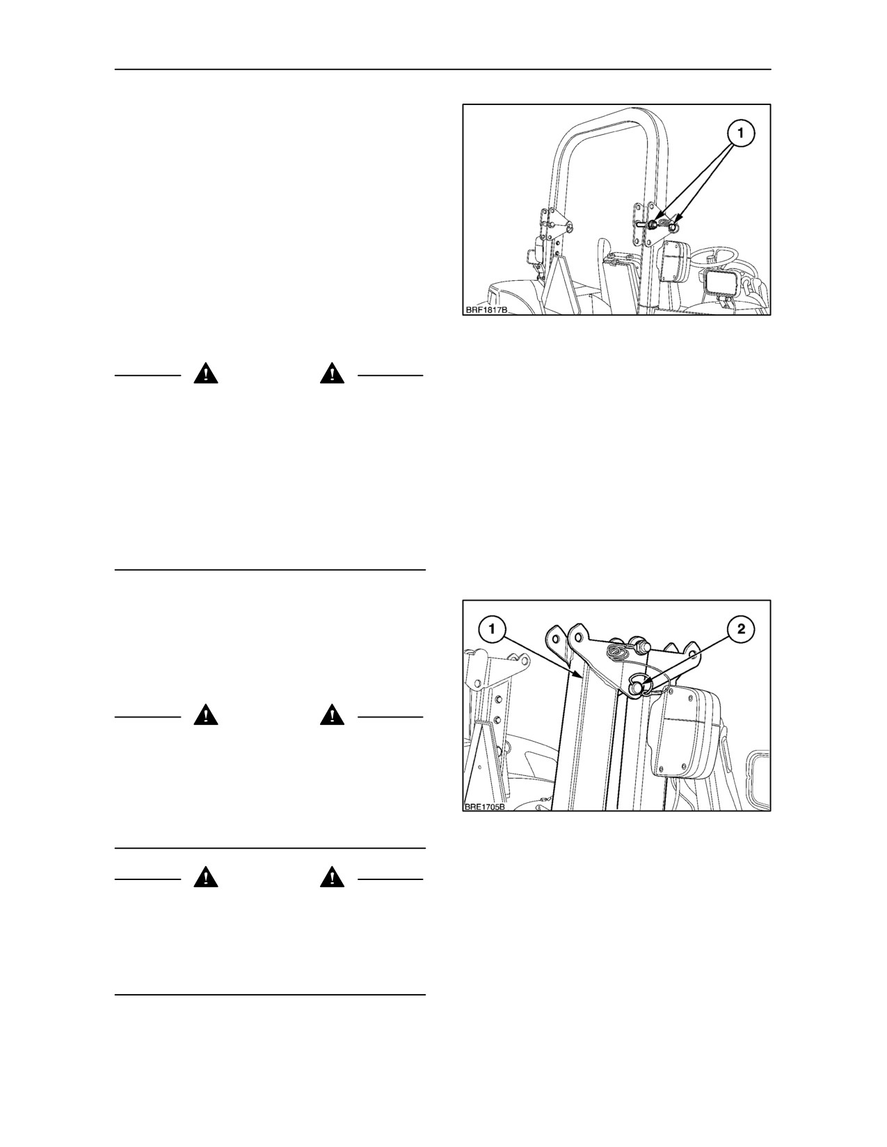
The roll bar
(ROPS) is designed to be folded
rearwards for use in low clearance operations. When
in the normal, upright, operating position it is secured
by two locking pins (1).
The ROPS is shown folded in the low clearance
position in Figure 2.
The ROPS must always be maintained in a
serviceable condition.
NOTE: Do not attempt to fold the ROPS if a canopy
1
is fitted.
WARNING
When improperly operated, a tractor can roll over.
For low clearance use only, the roll bar may be
lowered. No protection is provided when the tractor
is operated with the roll bar in the lowered position.
Always raise the roll bar immediately after low
clearance use. When the tractor is being driven from
a low clearance job, the roll bar should be in the
raised position. Always use the seat belt when the roll
bar is raised. Seat belts save lives when they are
used. Do not use the seat belt when the roll bar is
lowered.
To fold the roll bar to the low clearance position,
unclip the linch pin and remove the locking pin (2)
from both sides of the roll bar. Lower the upper
section of the roll bar (1) rearwards and insert the
locking pin in the lower hole, as shown. Secure both
locking pins with the linch pins.
WARNING
Do not attach chains or ropes to the ROPS for pulling
purposes as the tractor may tip backwards. Always
pull from the tractor drawbar. Be careful when driving
through door openings or under low overhead
objects. Make sure that there is sufficient overhead
clearance for the ROPS. Lower the ROPS, if
2
necessary.
WARNING
If the machine has rolled over or the ROPS has been
in some other type of accident (such as hitting an
overhead object during transport), you must replace
the damaged ROPS components to get as much
protection as you had originally. DO NOT TRY TO
WELD OR STRAIGHTEN THE ROPS.
2--6
SECTION 2 -- CONTROLS, INSTRUMENTS AND OPERATION
CAB (where fitted)
NOTE: The controls on tractors without a cab, from
the instrument console down, are very similar to
those with a cab. Even if your tractor does not have
a cab, you should still read the following text to gain
an understanding of the function and use of the
controls.
Introduction
The cab on your tractor has been designed to provide
operator protection, comfort and convenience.
Inside, the trim panels, roof, and floor are insulated
to reduce noise to a minimum.
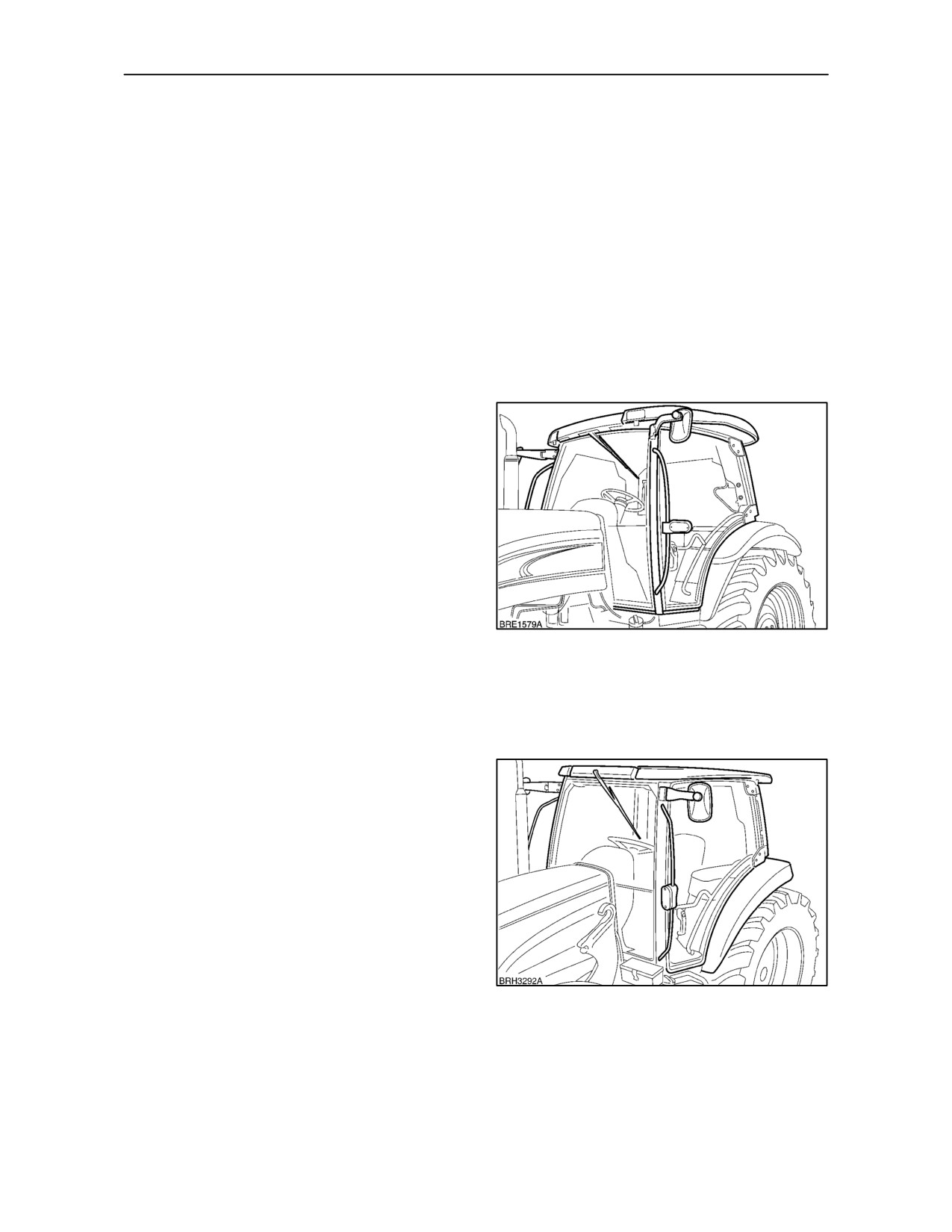
Two wide opening doors permit entry to the cab from
either side, aided by convenient grab handles and
footsteps with anti-slip treads. The doors and rear
window are fitted with gas struts to hold them in the fully
open position. Additionally, the rear window may be
retained in the partially open position for increased
ventilation.
Standard Cab
Standard cab features include a fresh air
heater/defroster, high visibility roof panel, front and rear
wash/wipe, sun visor, tinted glass, interior light and
exterior courtesy lights, cigarette lighter, storage
3
facilities, interior/exterior rear view mirrors and a choice
of comfortable seats.
Options include air-conditioning, radio, opening front
windscreen and extending exterior rear view mirrors.
Low Profile Cab
When fitted with the optional low roof, the overall cab
height is reduced by approximately 2.15 cm. (5.5 in.)
allowing operation in areas of restricted height. The
standard specification with low roof includes fixed
high visibility roof panel, air conditioning and a
pre--wired
disposition
for
the
optional
radio/cassette/CD player.
4
2--7
SECTION 2 -- CONTROLS, INSTRUMENTS AND OPERATION
External Door Handle
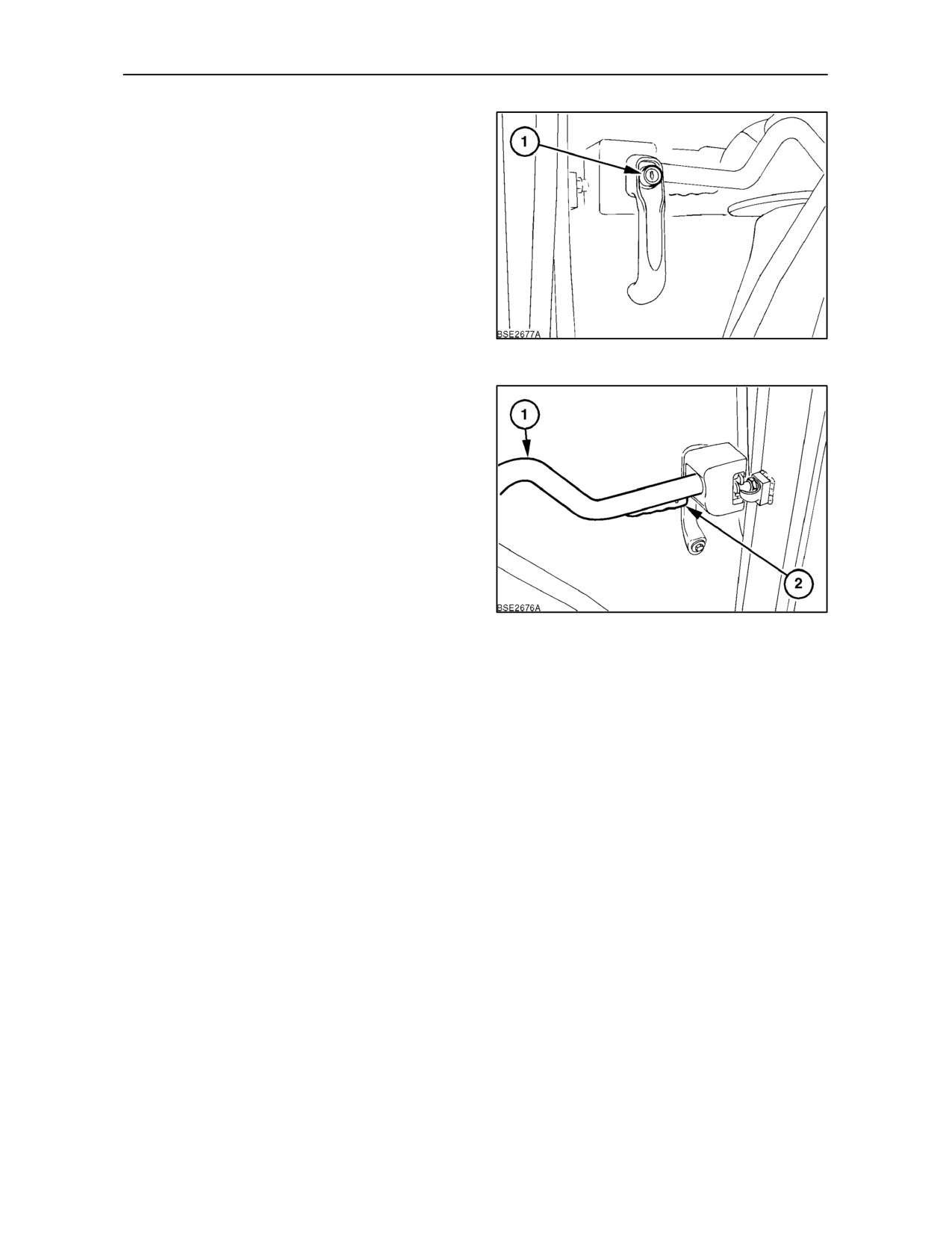
Each door has an external handle with a push button
(1). The door may be locked from the outside using
the key provided.
5
Interior Door Handle
To open a door from inside the cab, squeeze up the
trigger (2) on the underside of the grab handle (1).
Use the grab handle to push the door open.
6
2--8
SECTION 2 -- CONTROLS, INSTRUMENTS AND OPERATION
Entering and Exiting the Cab
Wherever possible, the cab should be entered from
the left side.
WARNING
Do not grasp the gear levers when entering the cab
from the right-hand side. Use only the grab handles
provided on the frame and door.
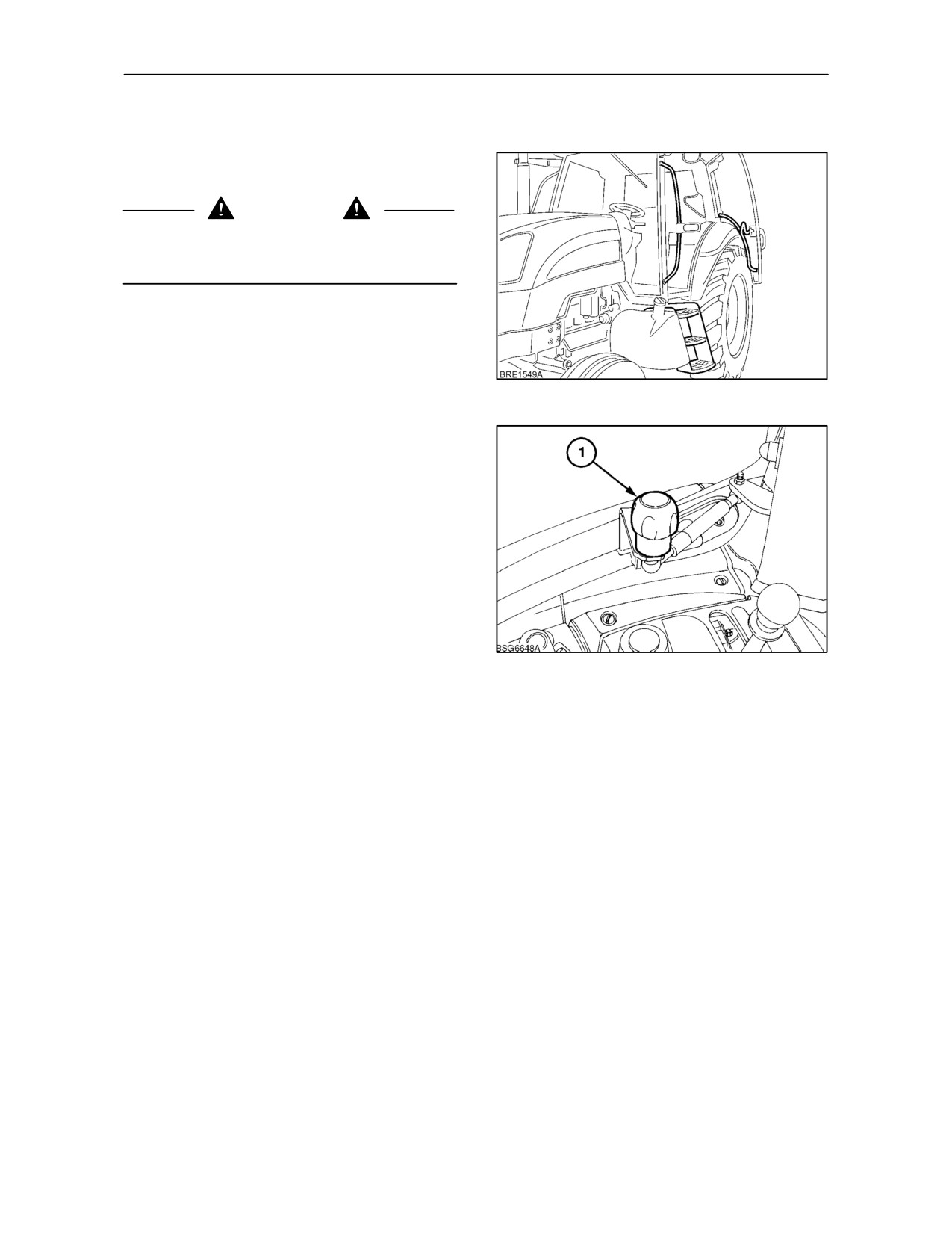
To enter the cab, face the door, then open it. Place
one foot on the lowest step plate and, using the grab
handles on the ‘A’ post and inside the door, climb the
steps and enter the cab.
7
Sit in the seat and, where fitted, pull the door closed
using the knob (1). Fasten the seat belt, if fitted.
To exit the cab, release the seat belt, open the door,
grasp the grab handles, back out of the cab and
descend the steps using the grab handles.
8
2--9
SECTION 2 -- CONTROLS, INSTRUMENTS AND OPERATION
Rear Window
The rear window may be locked in the closed position
or retained in the partially open or fully open
positions.
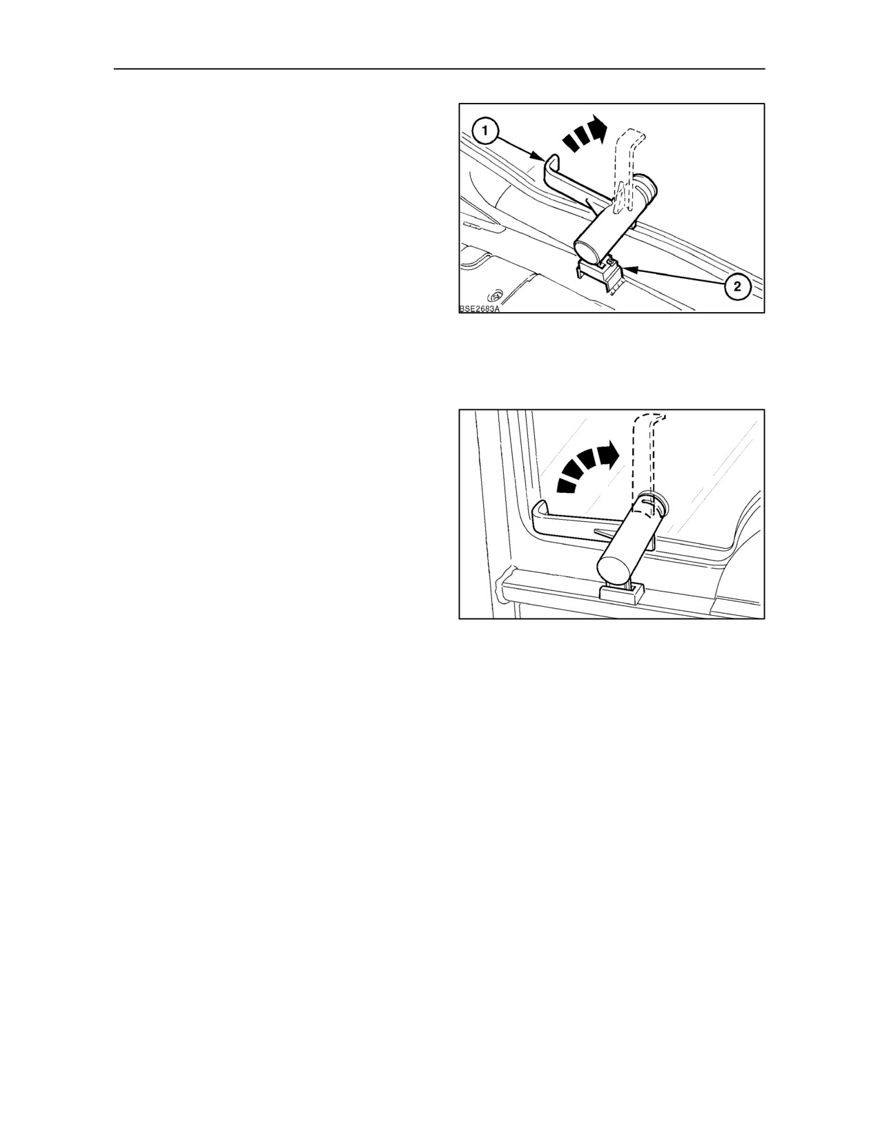
To open the window, lift the central locking handle (1)
up to the vertical position. Allow the window to open
a little then push the handle down so that the locking
tongue engages the slot
(2) in the framework.
Alternatively, the window may be allowed to swing
fully open supported by two gas-filled struts.
IMPORTANT: Retain control of the window when
9
opening it fully. Do not allow it to swing open freely.
Using the grab handle, pull the window closed and
push the handle down to lock the window.
Opening Front Windscreen (where fitted)
The front windscreen may also be locked in the
closed position or retained in the partially open or
fully open positions.
IMPORTANT: Retain control of the window when
opening it fully. Do not allow it to swing open freely.
To close the windscreen, pull on both handles
equally. Push the locking handles down to lock in
position.
10
2--10
SECTION 2 -- CONTROLS, INSTRUMENTS AND OPERATION
High Visibility Roof Panel -- Standard Cab
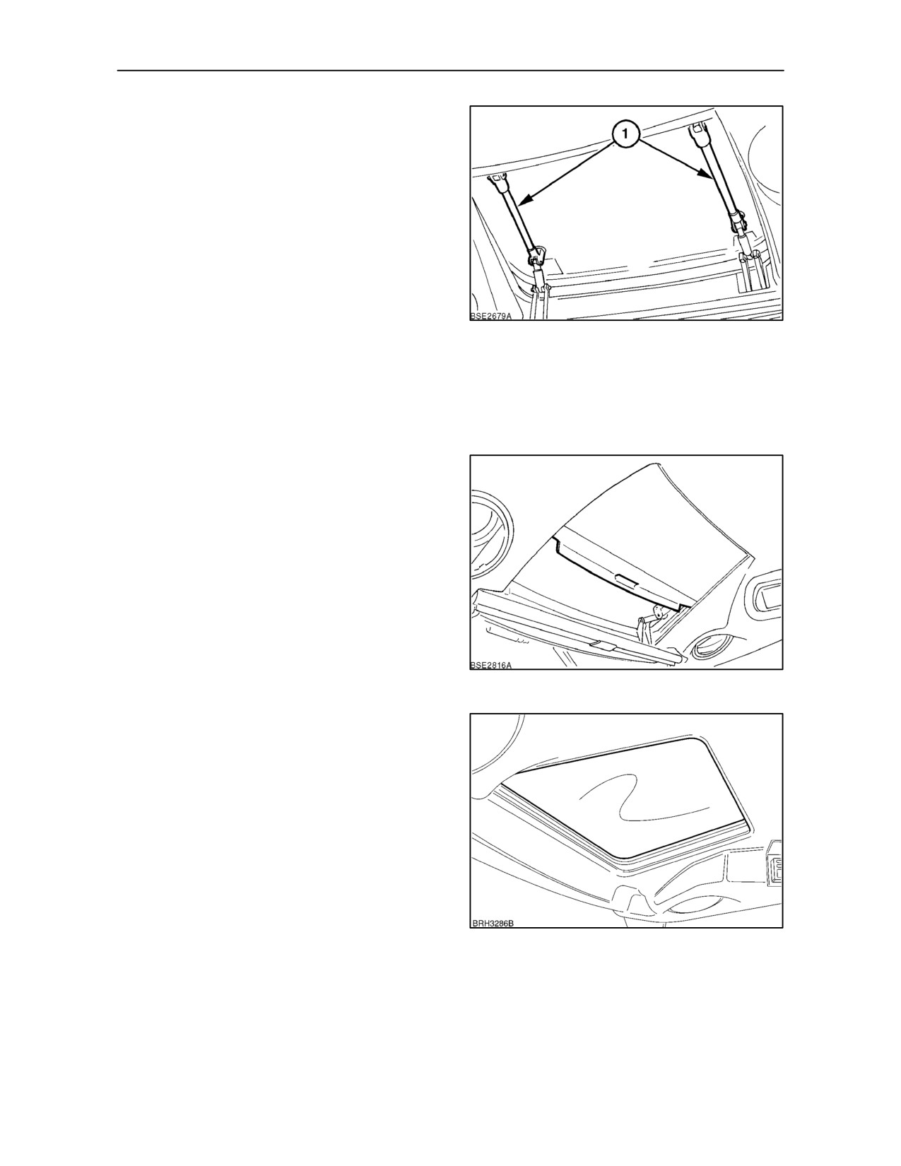
The high visibility roof panel provides the operator
with a view to the bucket or grab when the loader is
in the raised position.
For extra ventilation the roof panel may be tilted to
one of three positions. Using the grab handles (1),
push up at the front or rear to angle the panel.
Alternatively, pushing up in the centre of the grab
handles will fully open the panel.
To close the panel, grasp both handles and pull the
panel down, the spring action of the handles will hold
11
the panel in the closed position.
NOTE: When transporting the tractor on a truck or
trailer at speeds above 50 K/mh (31 MPH) ensure the
roof panel is secured to prevent accidental opening.
See page 3--3 for more information.
The sliding panel may be adjusted to reduce glare or
can be fully closed if required.
12
High Visibility Roof Panel -- Low Profile Cab
The high visibility roof panel on low roof cabs is of a
fixed type and cannot be tilted.
13
2--11
SECTION 2 -- CONTROLS, INSTRUMENTS AND OPERATION
Sun Visor -- Standard Cab
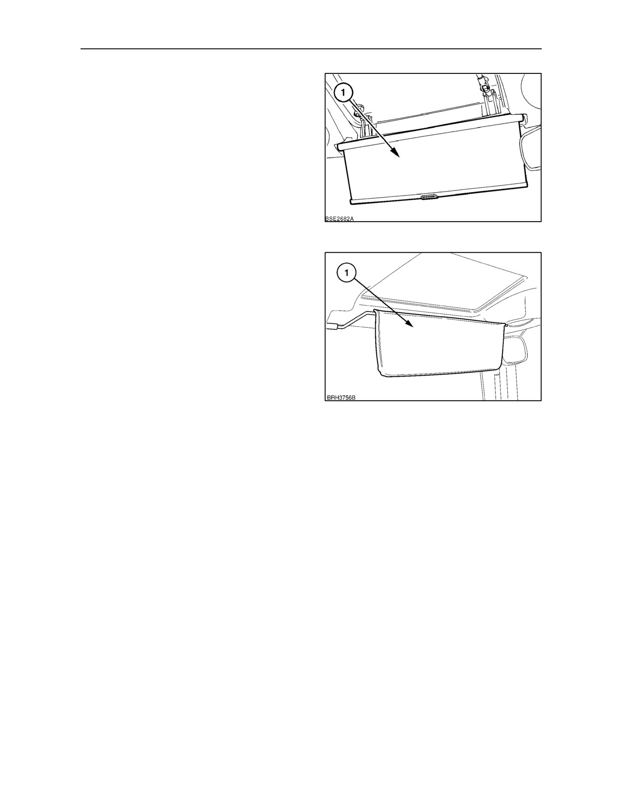
Pull down the sun visor (1) to protect the driver’s eyes
from the glare of the sun. The visor will remain in the
chosen position. Push the visor up to retract.
14
Sun Visor -- Low Profile Cab
The sun visor (1) can be used to protect the driver’s
eyes from the glare of the sun or to shade the interior
of the cab from strong sunlight coming through the
high visibility roof panel. Rotate downwards for glare
protection, upwards to shade the cab interior.
15
2--12
SECTION 2 -- CONTROLS, INSTRUMENTS AND OPERATION
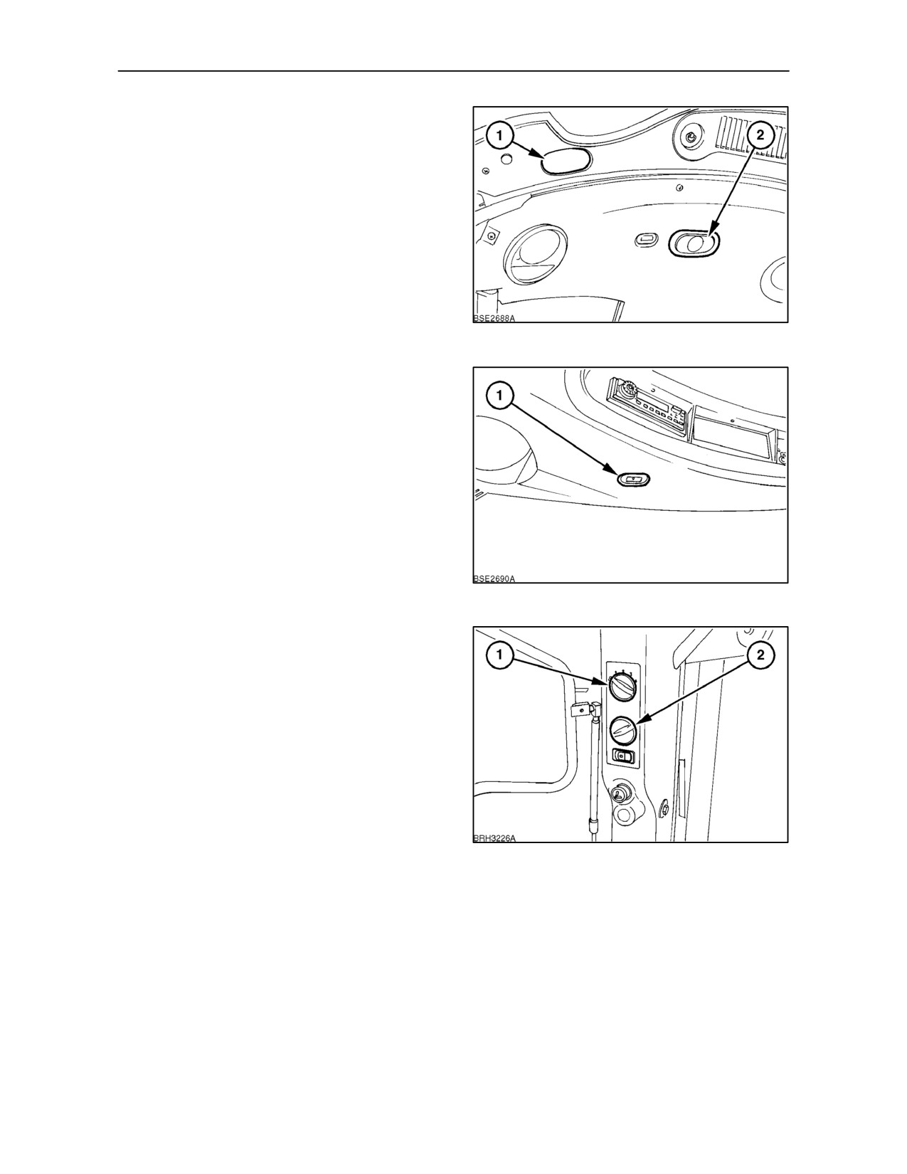
Interior Light
The interior light (2), has three operating positions.
Depress the front and the light will remain on,
depress the rear and the light will illuminate when
either of the doors are opened.
Where fitted, the courtesy light
(1), operates in
conjunction with the interior light. This light provides
illumination of the step area when the door is opened.
When the switch is in the central position, the light is
off, irrespective of the position of the doors.
16
Console Light
The light (1) provides a soft glow to the gear levers
and hydraulic console. The light is illuminated when
the tractor lights are turned on. On cabs with the
standard roof a second light is provided on the
left--hand side to illuminate the drinks holder and
storage box.
17
Heater Temperature Control
Turn the knob
(2) clockwise to increase the
temperature of the air from the heater. Turn fully
anti-clockwise to obtain unheated air from the heater
vents.
Blower Control
A 4-speed blower is installed for the heater (and air
conditioner, where fitted). Turn the switch
(1)
clockwise to the first position for low speed. Further
rotation of the switch in a clockwise direction will
increase the fan speed.
18
With the windows closed, the blower may be used to
pressurise the cab to exclude dust etc. Provided that
the cab air filters are serviced correctly, maximum
pressurisation and optimum dust exclusion may be
achieved by operating the blower at maximum fan
speed.
2--13
//////////////////////////////////////////