New Holland T6010, T6020, T6030, T6050, T6070 Delta and Plus Tractors. Operator's Manual - page 2
SECTION 2 -- CONTROLS, INSTRUMENTS AND OPERATION
Air Recirculation
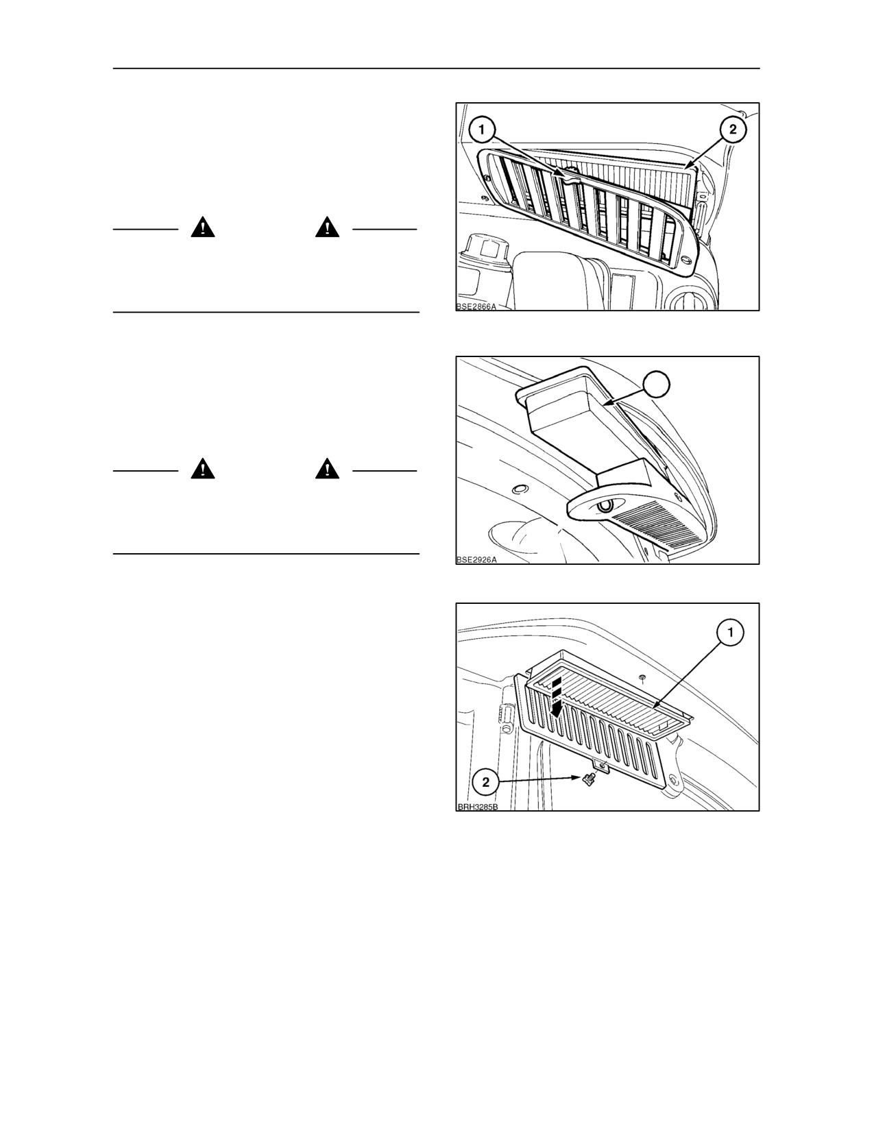
The cab ventilation system has three filters, two
external filters through which fresh air is drawn into
the cab, and one internal air re--circulation filter (2).
Move the slider control (1) fully to the right for
maximum air re--circulation.
WARNING
The cab air filter is designed to remove dust from the
air but will not exclude chemical vapour. Follow the
chemical manufacturer’s directions regarding
protection from hazardous chemicals.
19
Cab Air Filters
1
When operating with pesticides, both internal
(re--circulation) and external cab air filters (1), may
be replaced with special charcoal filters. Consult
your authorised dealer.
CAUTION
Use only genuine New Holland filter elements when
renewing cab air filters. When replacing used filters,
follow local regulations in the disposal of
contaminated elements.
20
Safety Precautions
Although it is possible to pressurise the cab interior
to reduce ingress of chemical vapour, the
recommended safety procedures, as stipulated by
the chemical manufacturer, should be observed at all
times.
Protective clothing worn when filling the sprayer with
pesticides or when carrying out external
adjustments, should be removed and stored away
carefully before re--entering the tractor cab.
To prevent build--up of chemical residue inside the
cab, the interior trim and floor covering should be
21
wiped clean with a damp cloth on a regular basis.
2--14
SECTION 2 -- CONTROLS, INSTRUMENTS AND OPERATION
Cab Pressurisation Monitor (where fitted)
To improve protection against chemical vapours
entering the cab when spraying, the blower can be
used, in conjunction with charcoal filters, to raise the
air pressure inside the cab above that of the external
air pressure. Whilst this differential is maintained,
chemical vapours should not enter the cab. Ensure
all cab apertures are fully closed. To monitor the
internal pressure, a gauge is mounted inside the cab.
Cab Air Pressurisation Gauge
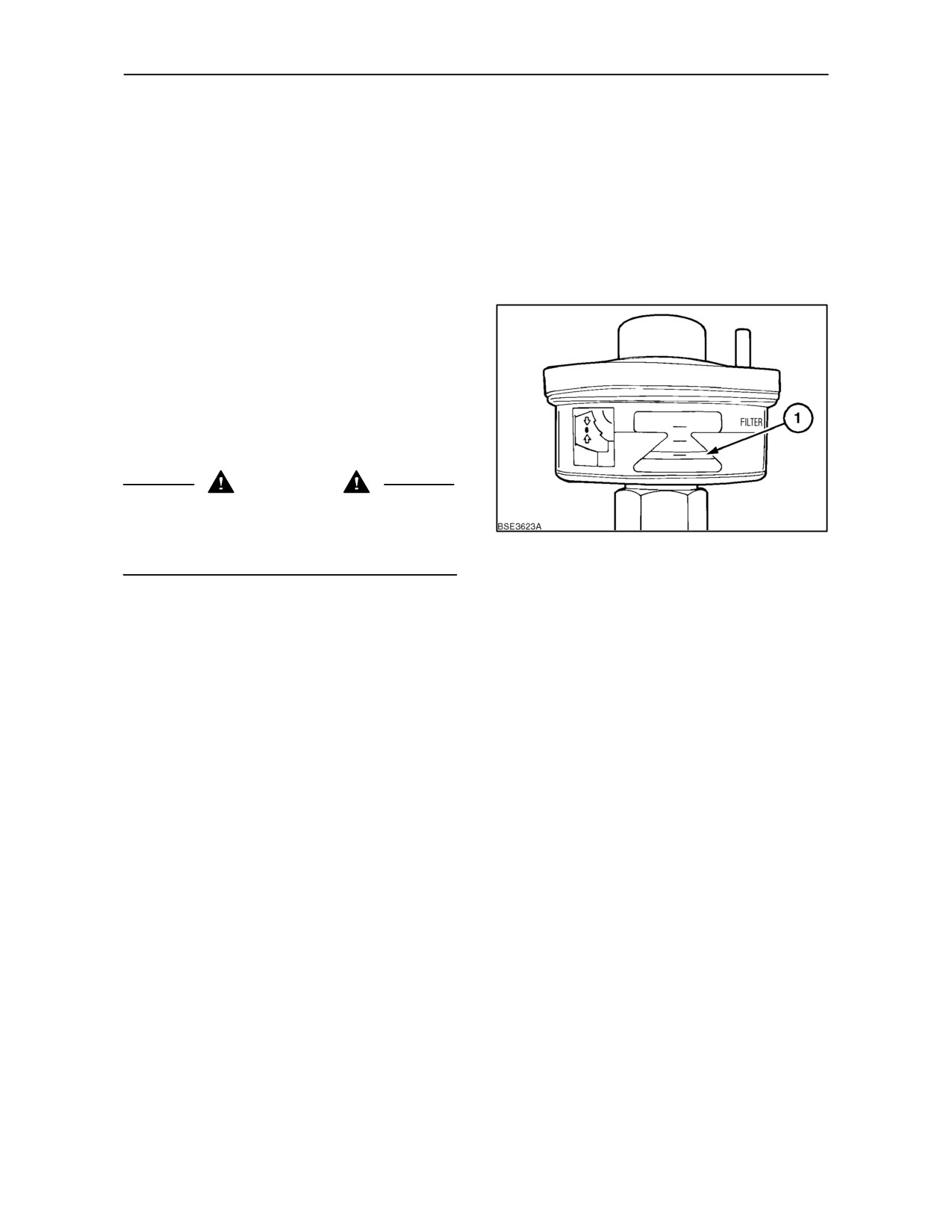
Observe the reading on the pressure gauge. If the
lower edge (1) of the yellow indicator centres in the
green area you have an adequate differential
between the internal and external air pressure.
Adjust the blower speed to maintain that reading. If
the yellow indicator rises into the red area, increase
blower speed to raise the internal cab pressure.
CAUTION
If, during spray operations, the lower edge of the
yellow indicator enters the red section of the gauge,
carry out the checks below and follow the chemical
22
manufacturers recommendations for safe operation.
With the blower in the off position the yellow indicator
should move into the red area. If the indicator does
not register correctly, the gauge should be replaced
before operating with chemical spray equipment.
If the blower is unable to maintain the correct
pressure inside the cab then the following checks
should be made to determine the cause.
1. Check blower is on maximum speed.
2. Ensure all doors, windows and roof panel are
fully closed.
3. Check external air filters for blockage or
restriction.
4. Examine all cab aperture seals for damage.
5. Check sealing around linkages and levers where
they pass through the cab panels.
If, after all the checks have been made the cab
interior pressure cannot be maintained, consult your
authorised dealer.
2--15
SECTION 2 -- CONTROLS, INSTRUMENTS AND OPERATION
Adjustable Air Vents
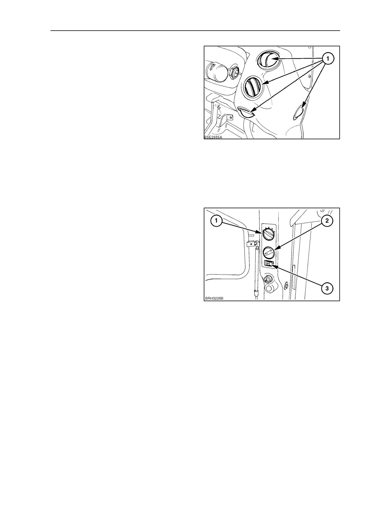
Adjustable air vents are provided throughout the cab
for even distribution of heated or cooled air. Vents are
located each side of the operators seat and on the
instrument console. Each vent may be
independently adjusted to direct the air flow (with the
blower control actuated) onto the side windows or the
operator. The two vents located on the upper part of
the instrument console may be adjusted to demist
the windscreen.
To open the circular vents (1) each side of the
instrument console, press one side of the disc and
23
then turn it, as required, to direct the air flow.
Lift the tag on the rectangular vents to open, and then
adjust for air flow and direction as required.
Air Conditioner Switch
(where fitted)
Depress the switch (3), to activate the air conditioner
compressor and lower the temperature of the air
within the cab. The air conditioner will only operate
with the blower (1) switched on.
IMPORTANT: The air conditioning system uses
R134A refrigerant. Do not mix with other refrigerants.
To quickly reduce in cab temperature operate the air
conditioner with the blower speed set to maximum
and the heater control fully off. When the air has
cooled sufficiently, adjust the blower control to
maintain the desired temperature. The windows and
doors should remain closed.
24
Under certain conditions, it may be desirable to
operate both the air conditioner and heater together,
e.g. to demist the windscreen and interior door glass
on a cold morning. (The air conditioner, as well as
cooling, also removes moisture from the air). Run the
engine to normal operating temperature, turn the
heater temperature control (2) and blower control (1)
to the maximum settings (fully clockwise). Turn on
the air conditioner (3) and adjust the air vents to
direct the air flow, as required.
2--16
SECTION 2 -- CONTROLS, INSTRUMENTS AND OPERATION
When the windows are clear, turn the air conditioner
off and adjust the heater controls to maintain the
desired cab air temperature.
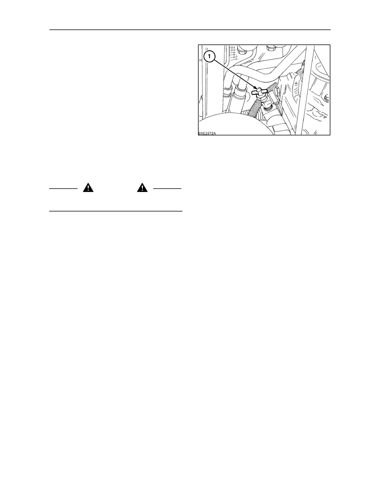
NOTE: At the start of the warm season, when the
heater is no longer required, it is recommended that
you close the heater shut-off valve (1), located at the
rear of the cylinder head.
IMPORTANT: Run the engine at idle speed for at
least 3 minutes after switching on the air conditioner,
if the air conditioner has been out of use for more
than 30 days.
25
IMPORTANT: Always turn the air conditioner off
when cooled or de-humified air is not required. For
proper operation of the air conditioner, ensure that the
cab air filters are serviced regularly. See section 4.
WARNING
The refrigerant used in the air conditioner system
has a boiling point of --12° C (10° F).
• Never expose any part of the air conditioner
system to a direct flame or excessive heat
because of the risk of fire or explosion.
• Never disconnect or disassemble any part of the
air conditioner system. Escaping refrigerant will
cause frostbite. Allowing refrigerant to escape
into the atmosphere is illegal in many countries.
• If refrigerant should contact the skin, use the
same treatment as for frostbite. Warm the area
with your hand or lukewarm water at 32 -- 38° C
(90 --100° F). Cover the area loosely with a
bandage to protect the affected area and to
prevent infection. Consult a doctor immediately.
• If refrigerant should contact the eyes, wash the
eyes immediately with cold water for at least 5
minutes. Consult a doctor immediately.
NOTE: It is the normal function of the air conditioner
to extract water from the air. Drain hoses lead from
the air conditioner unit to a point beneath the cab. Do
not be concerned if a pool of water collects beneath
the drain hose outlets when the engine is stopped.
2--17
SECTION 2 -- CONTROLS, INSTRUMENTS AND OPERATION
Radio/Cassette/CD Player
(where fitted)
With Standard Cab
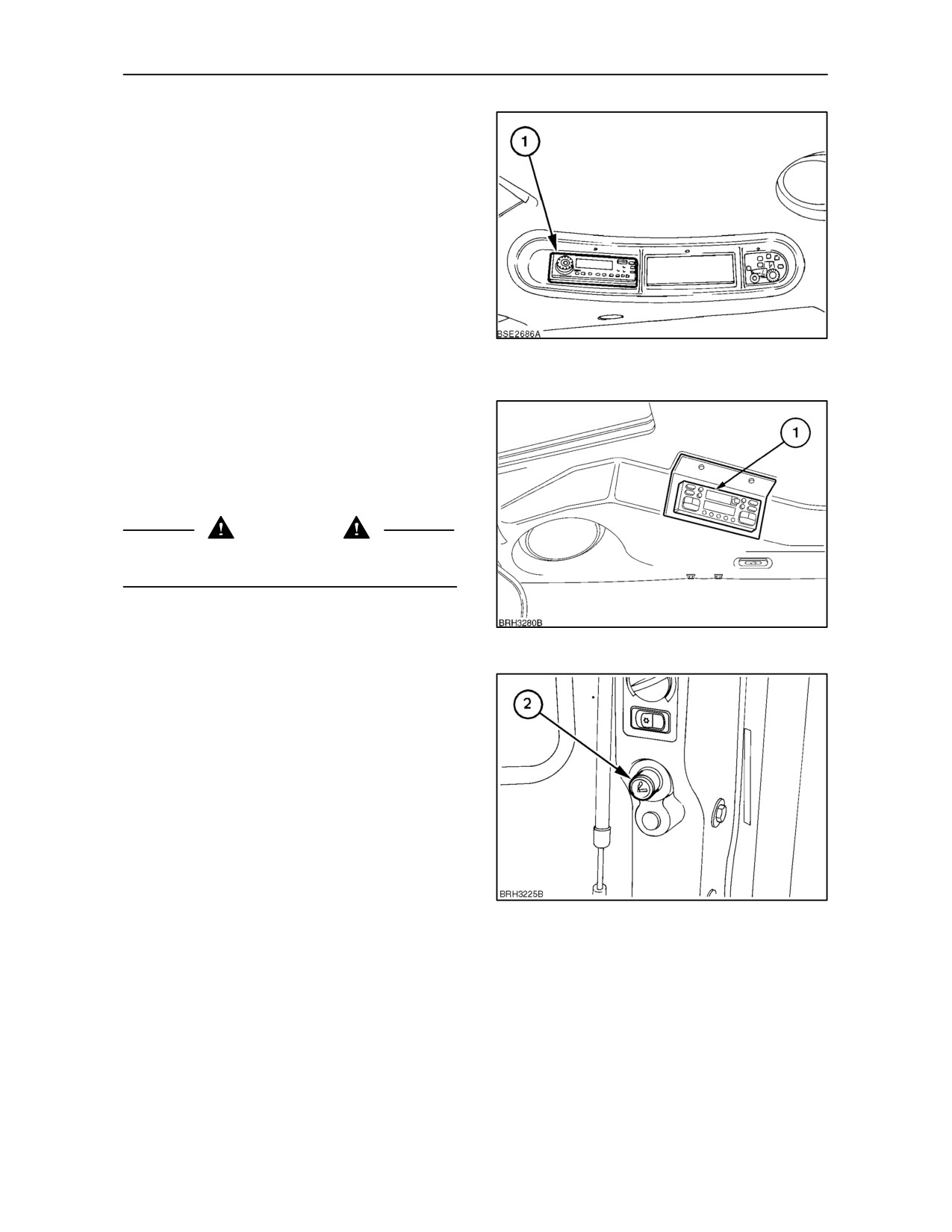
The cab is pre-wired and has two speakers installed
in the roof (four speakers are available as a dealer
installed accessory). A choice of self-seeking
AM/FM stereo radio/cassette or radio/CD players (1)
are also available as a dealer installed accessory.
Separate operating instructions will be supplied with
the radio.
NOTE: The radio will only operate with the key-start
26
switch in the on or accessories position.
With Low Profile Cab
The dealer installed radio/cassette or radio/CD
player (1) is located in the cab roof to the right of the
driver. Separate operating instructions will be
supplied with the unit.
WARNING
Ensure the aerial is positioned so it cannot touch
overhead power lines.
27
Cigar/cigarette lighter
Press the lighter button (1) fully in to activate. When
the electrical element has reached the correct
temperature, it will pop out ready for use.
28
2--18
SECTION 2 -- CONTROLS, INSTRUMENTS AND OPERATION
Work Lamp and Beacon Switch Panel
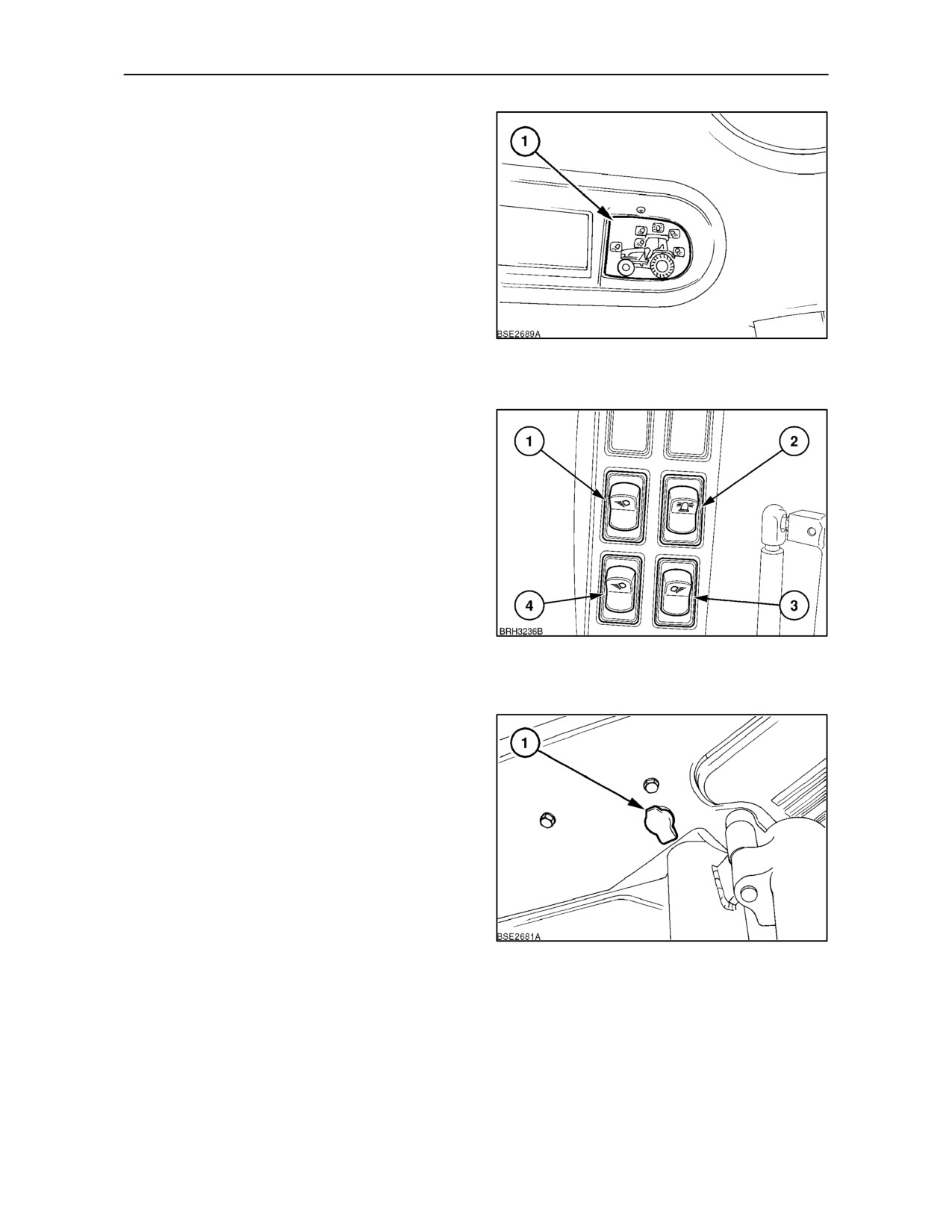
NOTE: The work lamps will only operate with the
tractor lights switched on.
With Standard Cab
The switches are located on a panel mounted in the
roof console (1). Individual switches control the front
and rear work lamps and the rotating beacon (where
fitted). Depress the switches once to illuminate,
depress again to turn the lamps off.
When the key-start switch is turned on, the switches
29
will be internally illuminated. The light intensity will
increase as each switch is activated.
With Low Profile Cab
The worklamp and beacon switches are located on
the right--hand cab ’C’ pillar. Depress the lower part
of the switch to operate the light.
1. Grab rail mounted worklamps
2. Roof beacon
3. Rear worklamps
4. Front lower worklamps (engine hood)
NOTE: Do not adjust a fender-mounted, rear work
lamp to point fully downwards. The heat generated
30
by the work lamp may distort the plastic housing of
the rear lamp cluster.
Beacon Power Socket
Two power sockets for the rotating beacon are
provided at the rear of the cab, one on each side.
31
2--19
SECTION 2 -- CONTROLS, INSTRUMENTS AND OPERATION
In Cab Storage
(where fitted)
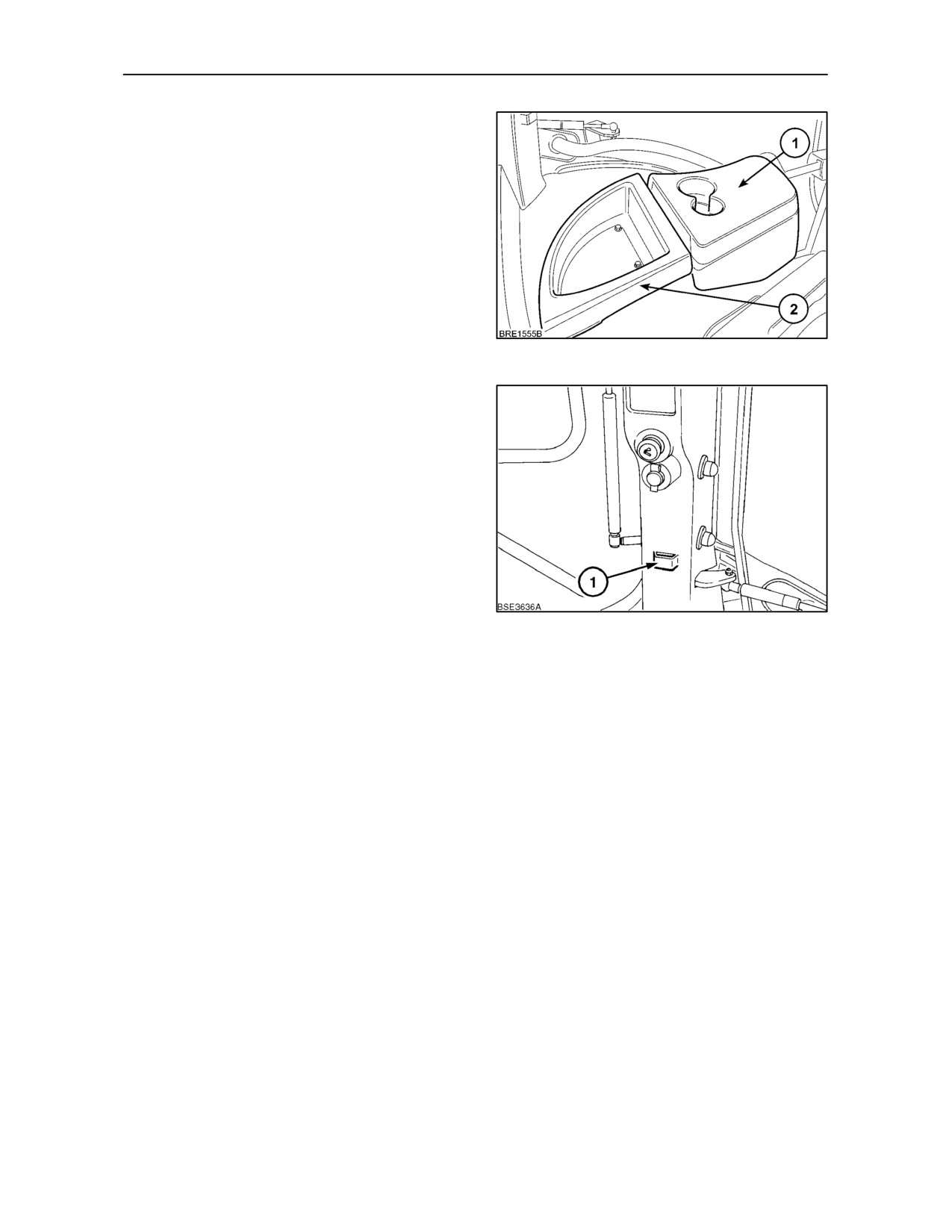
A storage box with a hinged lid (1) is located on the
left-hand side of the cab. The lid also incorporates a
drinks holder.
A recessed tray (2) is provided to the rear of the
storage box to hold small tools, oddments, etc.
32
Mobile Telephone Usage
A storage bracket (1) is provided on the left--hand
cab ’C’ pillar for a mobile telephone. Auxiliary power
for the telephone may be taken from the cigarette
lighter socket above.
33
2--20
SECTION 2 -- CONTROLS, INSTRUMENTS AND OPERATION
ELECTRICAL POWER CONNECTORS
INTERNAL POWER CONNECTORS
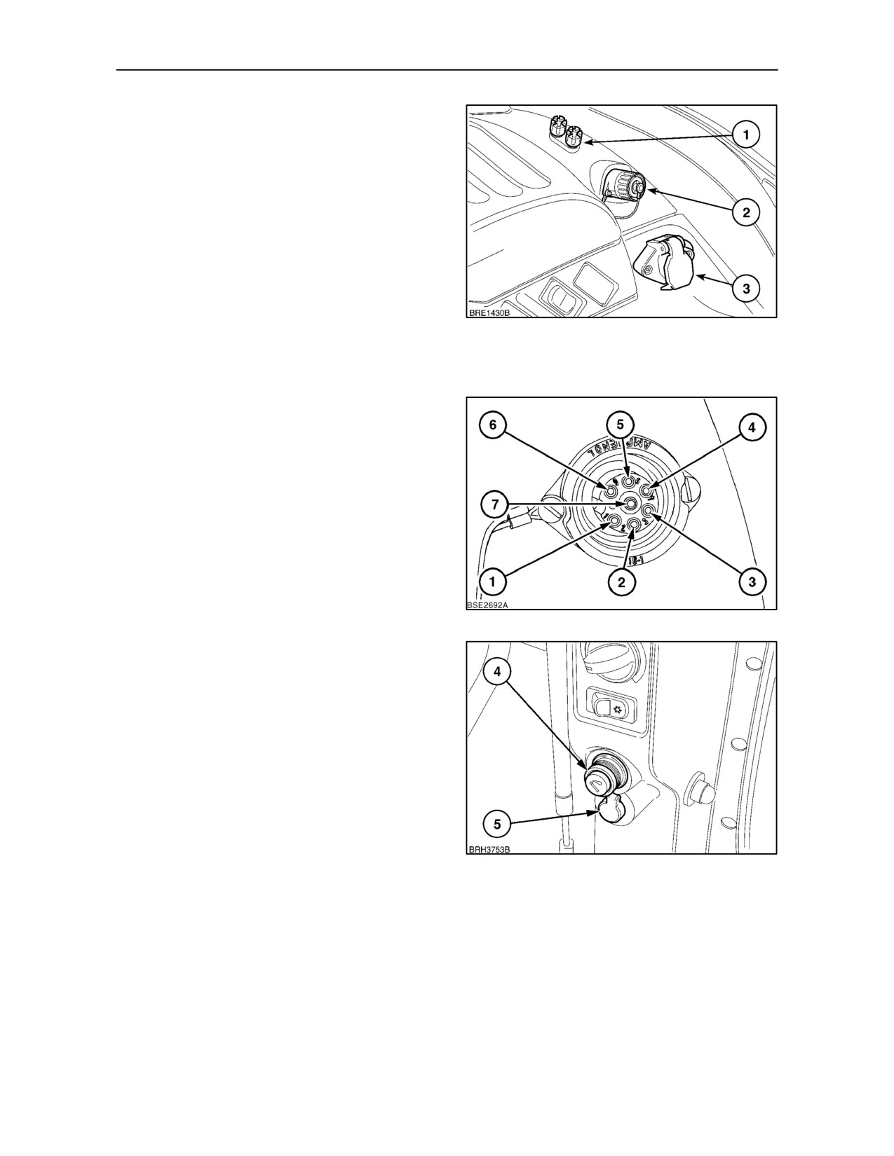
Depending on tractor specification there are a
number of electrical power connectors provided for
various applications. These are as follows:
1.
8 amp Screw terminals. The red terminal is
positive, the black terminal negative.
2.
7 Pole Din/ISO implement socket (with radar
option only) provides the information below.
34
3.
30
amp ISO/JD implement power socket.
Provides constant and key--start switched live
feeds.
7 Pole Din/ISO Implement Socket Connectors
Pin 1. True ground speed. (Radar Sensed)
Pin 2. Theoretical ground speed.
(Wheel Sensed)
Pin 3. Rear P.T.O. speed.
Pin 4. Rear 3--point hitch, in work/out of work.
Pin 5. Not used
Pin 6. 5 amp power supply.
Pin 7. Common ground connection.
35
4. Cigarette lighter/auxiliary power socket for
mobile telephone or cooler box (where fitted).
5.
8 amp Single pole auxiliary power socket. Live
with key--start in ’on’ position.
IMPORTANT: To ensure that terminals and
connecting cables do not get excessively hot when
loaded with near maximum current it is important to
make secure, tight connections to prevent
overheating and damage. Ensure that equipment is
connected to the terminals with cables of suitable
gauge and insulation thickness and fitted with
appropriate terminal connectors.
36
2--21
SECTION 2 -- CONTROLS, INSTRUMENTS AND OPERATION
Diagnostic Socket
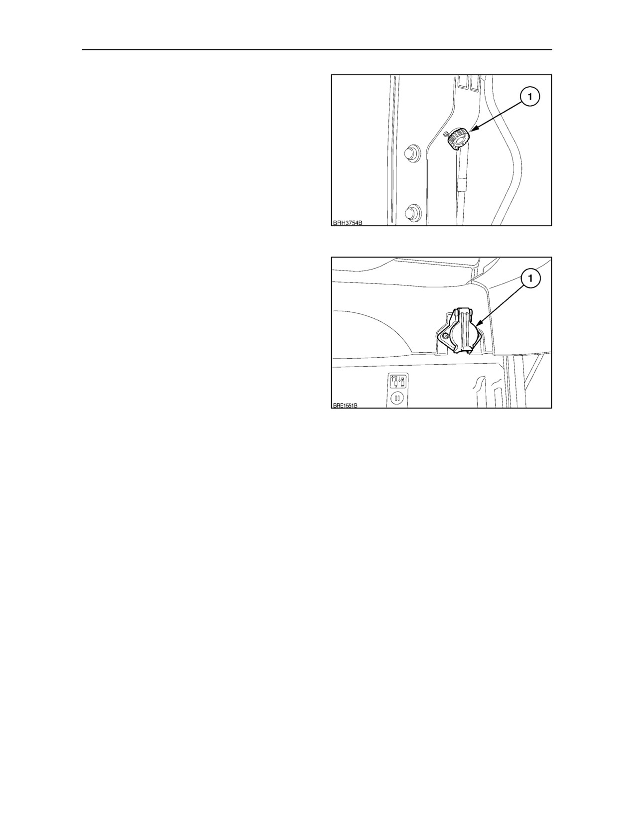
IMPORTANT: The multi--pin socket (1) on the cab ’C’
pillar is for use by an authorised dealer for connecting
diagnostic equipment to the tractor electronic
circuits. DO NOT attempt to connect any user
electronic equipment to this socket or damage may
be caused to the tractor electronic systems or control
units.
37
EXTERNAL POWER CONNECTORS
Four Pin Implement Socket
A 4-pin, 40 amp socket (1) is standard on all tractors
with cab. (See Section 7 for adaptor cable).
NOTE: The 4-pin socket provides power up to 40
amps. However, operator’s should be aware that the
screw terminals (4) Figure
34, share the same 40
amp fuse. The combined output of the 4-pin socket
and the screw terminals is, therefore, limited to 40
amps.
38
2--22
SECTION 2 -- CONTROLS, INSTRUMENTS AND OPERATION
Seven Pin Electrical Power Outlet
(except North America)
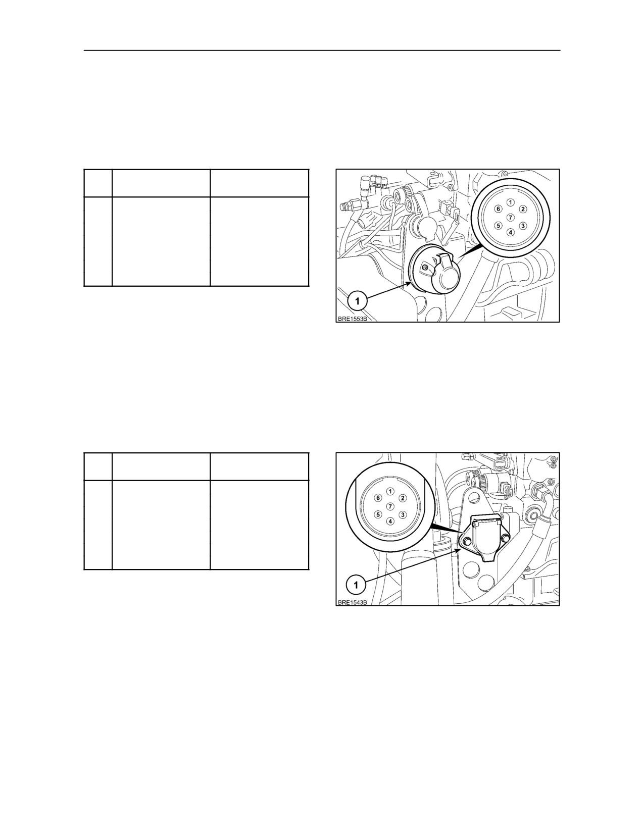
A standard 7-pin trailer lighting socket (1), is provided
and is mounted at the rear of the tractor. With
reference to the picture inset, the socket connections
(viewed from the front of the socket) are as follows:
Pin
No.
Wire Colour
Circuit
1.
Yellow
L.H. Turn Signal
2.
Not Used
--
3.
Black
Earth (Ground)
4.
Green
R.H. Turn Signal
5.
Blue
R.H. Parking Light
6.
Red
Brake Lights
7.
Brown
L.H. Parking Light
39
Seven Pin Electrical Power Outlet
(North America only)
A standard SAE 7-pin connector (1) is provided, to
operate the electrical system on implements and
trailers. With reference to the picture inset, the pin
connections (viewed from the front of the socket) are
as follows:
Pin
No.
Wire Colour
Circuit
1.
Black
Earth (Ground)
2.
Blue
R.H. Parking Light
3.
Yellow
L.H. Turn Signal
4.
Red
Brake Lights
5.
Green
R.H. Turn Signal
6.
Brown
L.H. Parking Light
7.
Not Used
--
40
2--23
SECTION 2 -- CONTROLS, INSTRUMENTS AND OPERATION
Cable and Harness Routing
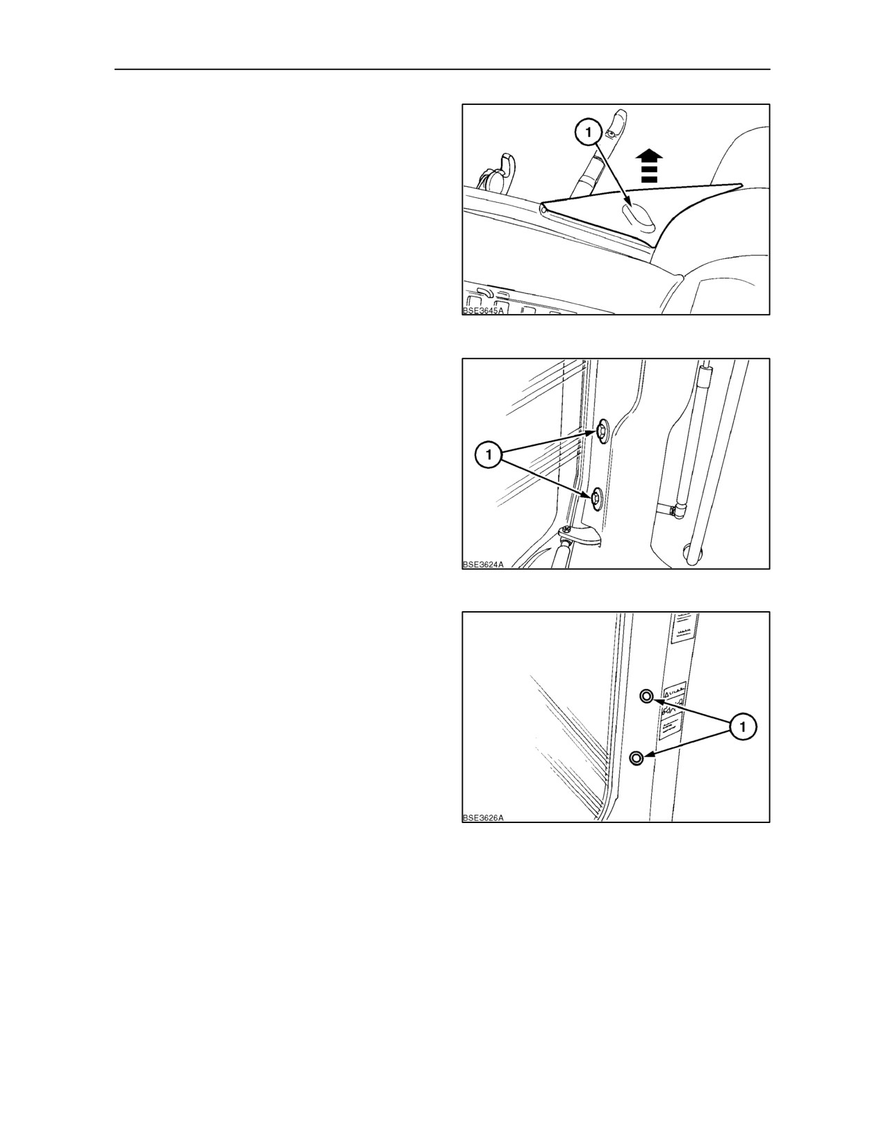
So the operating cable from the monitor may be
conveniently routed to the equipment, a small
aperture is provided in the filler plate each side of the
lower rear window frame. By making a small incision
in the rubber at (1), cables or wiring can be easily
routed through the filler plate.
41
Implement Monitor Installation
To facilitate installation of an implement monitor, two
mounting points are provided:
To meet SAE standards, captive bolts (1), protected
by plastic covers, are provided on the the right-hand
cab ’C’ pillar.
It is recommended that a bracket be screwed to the
‘C’ pillar to mount the monitor. A suitable bracket is
available from your authorised dealer.
42
An alternative monitor mounting position
(1) is
provided on the inner face of the right-hand ‘A’ pillar.
43
2--24
SECTION 2 -- CONTROLS, INSTRUMENTS AND OPERATION
SEATS
The seat installed on your tractor has a
comprehensive range of adjustments. Before
operating the tractor, it is important to adjust the seat
to the most comfortable position. See the following
text and appropriate illustration to identify the seat
installed in your tractor.
The seats shown have weight indicators registering
in kilos. A conversion chart from kg to lb is provided
for your convenience.
50 kg = 110 lb
90 kg = 198 lb
60 kg = 132 lb
100 kg = 220 lb
70 kg = 154 lb
110 kg = 245 lb
80 kg = 176 lb
120 kg = 265 lb
Standard Mechanical Seat (where fitted)
Seat height is adjustable in four positions. A release
handle (1), is located centrally, on the back of the
seat. Lift the release handle with one hand and lift or
lower the seat with the other. The seat will lock at the
selected height when the handle is released.
The suspension is adjusted by means of a folding
crank handle (1) Figure 45, on the front of the seat
frame. Sit in the seat and turn the handle until your
approximate weight, in kilos, is indicated in the
window (2).
44
The lever (3) controls seat travel. Lift the lever and
slide the seat forward or backward, as required.
When the lever is released, the seat will lock in the
position selected.
Folding armrests are provided. If not required, the
armrests may be raised to the vertical position.
45
2--25
SECTION 2 -- CONTROLS, INSTRUMENTS AND OPERATION
Deluxe Mechanical Seat (where fitted)
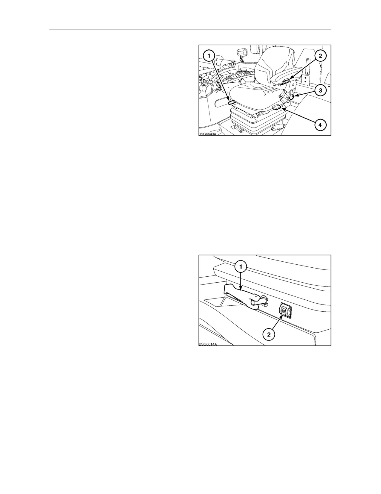
Lift the travel adjustment lever (1) and move the seat
forward or backward, as required. The seat will lock
in position when the lever is released.
There is a knurled wheel (2) on the underside of each
armrest. Turn the wheel to alter the angle of the
armrest.
If not required, both armrests may be lifted to the
vertical position.
The backrest may be tilted to suit the operator. Lift
46
the lever (3) on the left-hand side of the seat frame
and adjust the inclination of the backrest.
To facilitate observation of an implement attached to
the rear of the tractor, the seat may be allowed to
swivel. Adjustment is available as follows:
(a) Lock in one position 10° to the left of centre.
(b) Lock in one of two positions at 10° and 20°, to the
right of centre.
Lift the lever (4) and rotate the seat, as required. The
seat will lock in position when the lever is released.
Turn the crank handle (1) to adjust the suspension
until your approximate weight, in kilos, is indicated in
the window
(2). Turn the handle clockwise to
increase suspension stiffness to suit a heavier
operator and provide a firmer ride. Turn the handle
anti-clockwise and the seat suspension will become
softer.
The seat height is adjustable in three positions. With
the seat in the lowest position, grasp either side of the
seat cushion and lift the seat bodily until it locks in the
intermediate position. Lift the seat further and it will
lock in the maximum height position. To lower the
seat, lift the seat bodily to the fullest extent, to trip the
47
mechanism, then allow the seat to lower.
A storage pouch is provided on the back of the seat.
2--26
SECTION 2 -- CONTROLS, INSTRUMENTS AND OPERATION
Air Suspension Seat
(where fitted)
The air suspension seat provides a full range of
adjustments for driver comfort including an
electrically controlled air suspension system which
can be adjusted to suit individual operator weight.
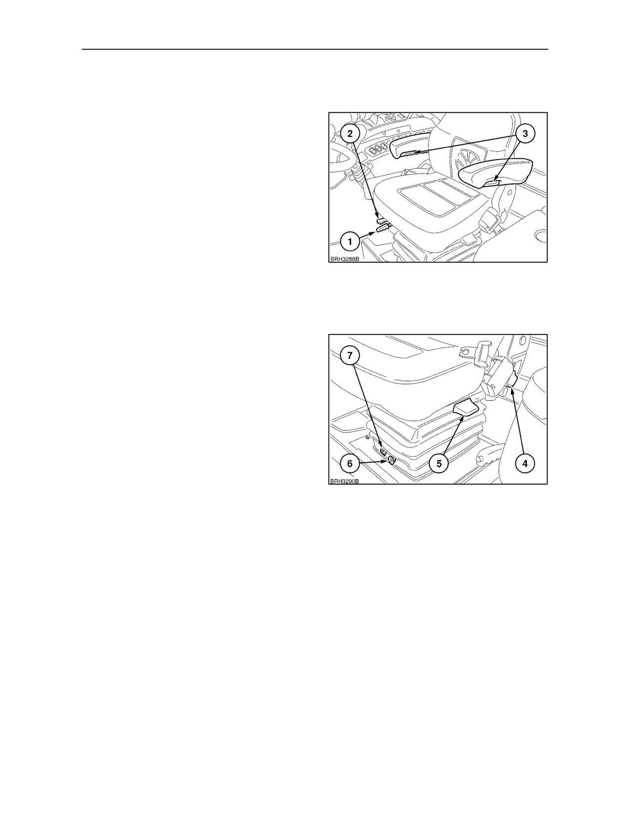
Lift the travel adjustment lever (1) to move the seat
forward or backward.
The seat is permitted a limited, spring controlled
fore/aft movement (float) when the travel isolator
lever (2) is moved to the left. Moving the lever to the
right will lock isolator movement.
The adjusters (3) on the underside of the armrests
48
may be turned to alter the angle of the armrests. Turn
them clockwise to raise the front of the armrests, turn
anti-clockwise to lower. Both armrests may be raised
to the vertical position if required.
The backrest may be tilted to suit the operator. Lift
the lever (4) on the left-hand side of the seat frame
and adjust the inclination of the backrest. The
backrest will lock in position when the lever is
released.
To facilitate observation of an implement attached to
the rear of the tractor, the seat may be rotated to the
left or right. Lift the lever (5) and rotate the seat as
desired. From the straight ahead position there are
two positions to the right and one to the left. Release
the catch to lock the seat.
Adjustments to the air suspension are made by
49
operating the air pump control button (6), a weight
indicator (7) will show the optimum setting for the
seat suspension.
A storage pouch is provided on the back of the seat.
The seat can be fitted with an optional upper back
support where required, consult your authorised
dealer.
2--27
SECTION 2 -- CONTROLS, INSTRUMENTS AND OPERATION
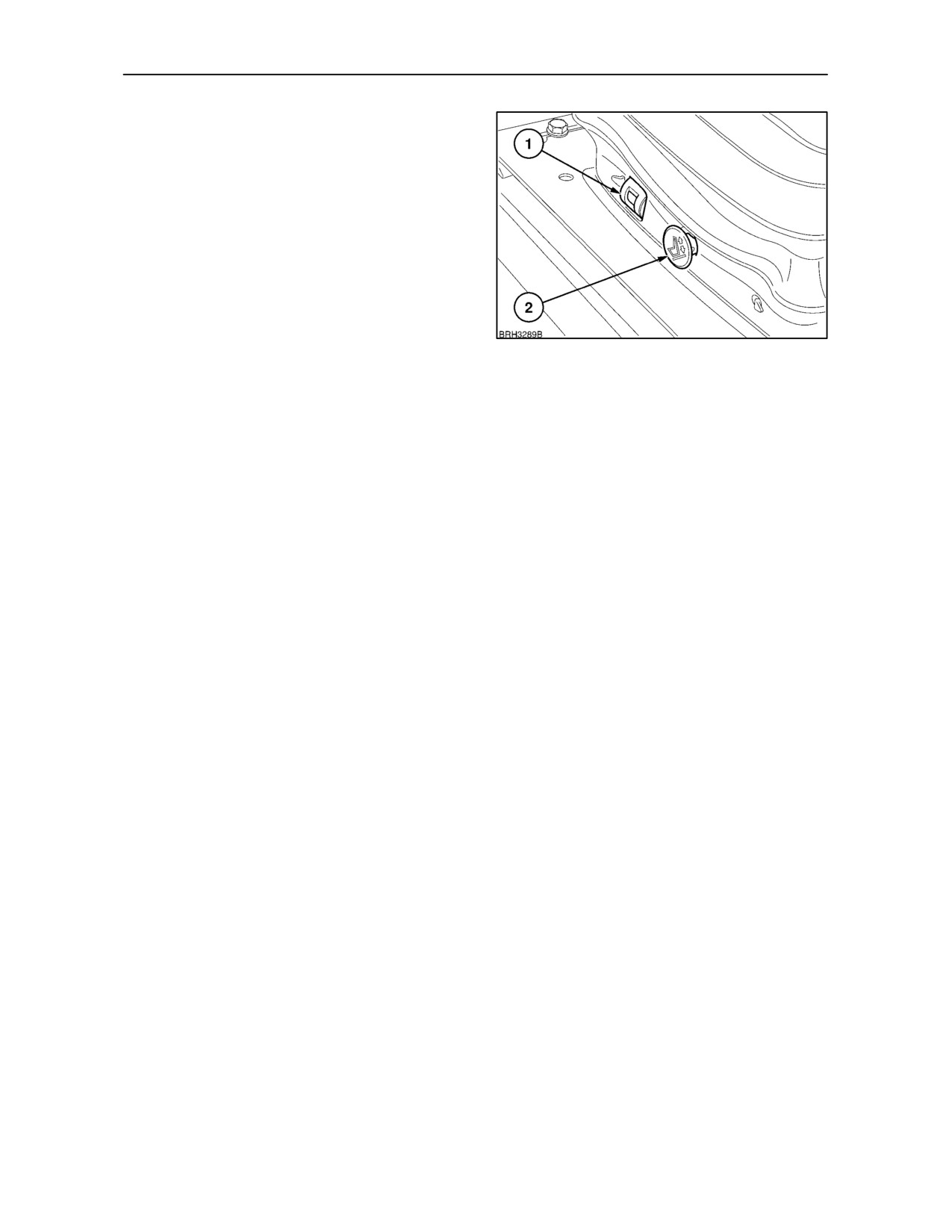
To set the initial suspension and ride height, first fully
lower the seat. Pull out the air pressure control (2)
and hold until all the residual pressure has been
released.
Further adjustments are now made with the key-start
switch turned on (warning lights illuminated).
Sitting in the seat, push--in and hold the control (2),
the air compressor will start to pressurise the
suspension. As the seat height increases, observe
the weight indicator (1), this will change from yellow
to green. When the indicator is completely green
release the control. To make further height
50
adjustments, operate the air compressor control, as
required, to raise or lower the seat.
NOTE: For optimum suspension performance, the
weight indicator should always be set in the green
segment with the tractor stationary and the operator
in the seat.
2--28
SECTION 2 -- CONTROLS, INSTRUMENTS AND OPERATION
Deluxe Air Suspension Seat
(where fitted)
The deluxe air suspension seat has electrically
controlled suspension. To make the initial
suspension adjustment, sit in the seat and hold the
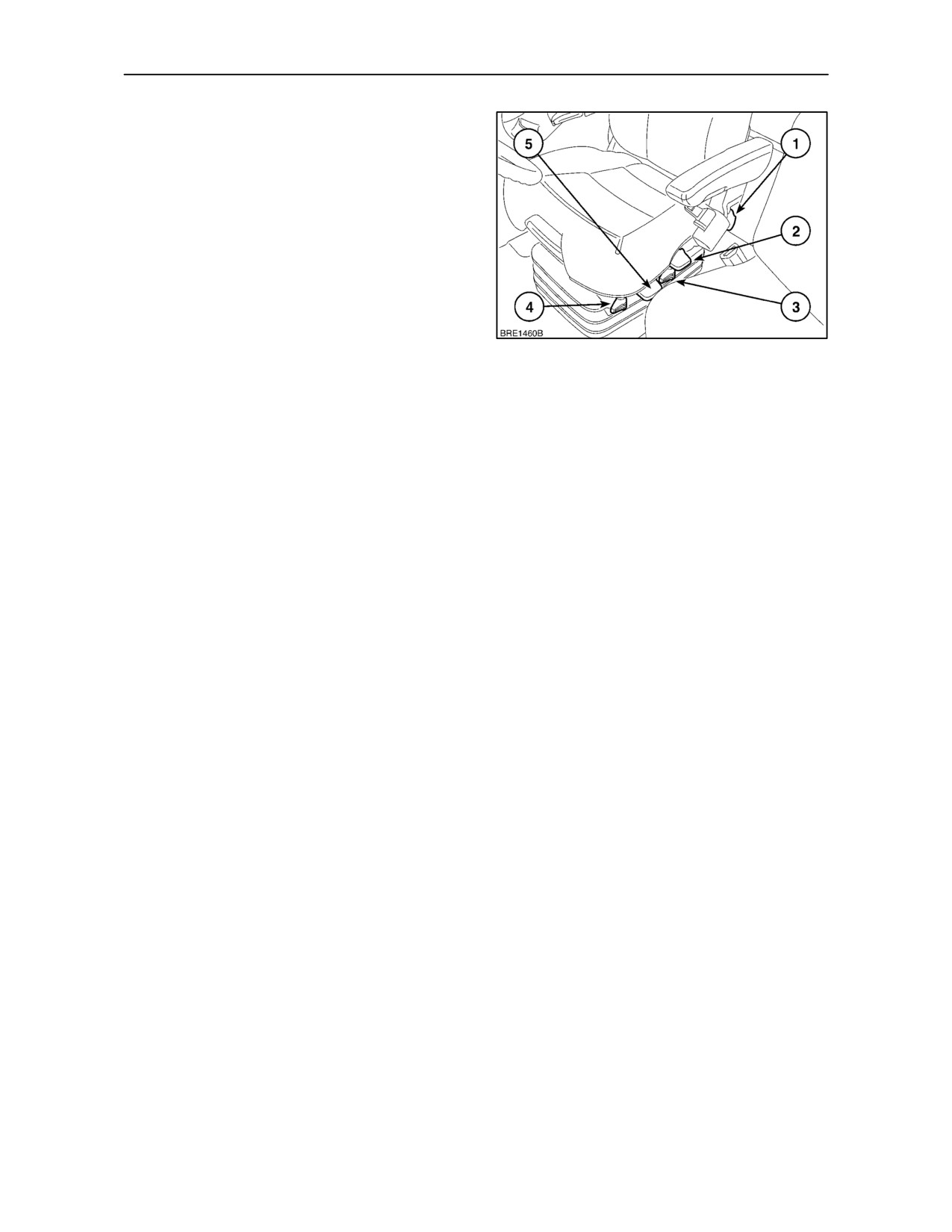
lever (2) down until the seat has fully lowered.
Further seat suspension and ride height adjustments
are made with the key-start switch turned on. Sit in
the seat and lift and release the lever (2). A servo will
raise the seat, automatically adjust to your weight
and stop when the optimum suspension setting is
reached. To make further height adjustments, hold
51
the lever up or down, as required, to raise or lower the
seat. When the lever is released, the seat will stop at
the height selected.
This setting will be maintained every time the
key-start switch is turned on or until such time as the
setting is re-adjusted.
The backrest may be tilted to suit the operator. Lift
the lever (1) on the left-hand side of the seat frame
and adjust the inclination of the backrest. The
backrest will lock in position when the lever is
released.
There are five damping settings for the suspension.
Bounce up and down in the seat while swivelling the
knob (3) from fully rearward (hard) to fully forward
(soft). Correct adjustment of the suspension, ride
height and damping, will provide the optimum in ride
comfort.
The seat is permitted a limited, spring controlled
fore/aft movement (float) when the travel isolator
knob (4) is swivelled to point rearward. Swivelling the
knob to point forward will lock the isolator movement.
To facilitate observation of an implement attached to
the rear of the tractor, the seat may be rotated to the
left or right. Lift the lever (5) and rotate the seat as
desired. From the straight ahead position there are
two positions to the right and one to the left. Release
the catch to lock the seat.
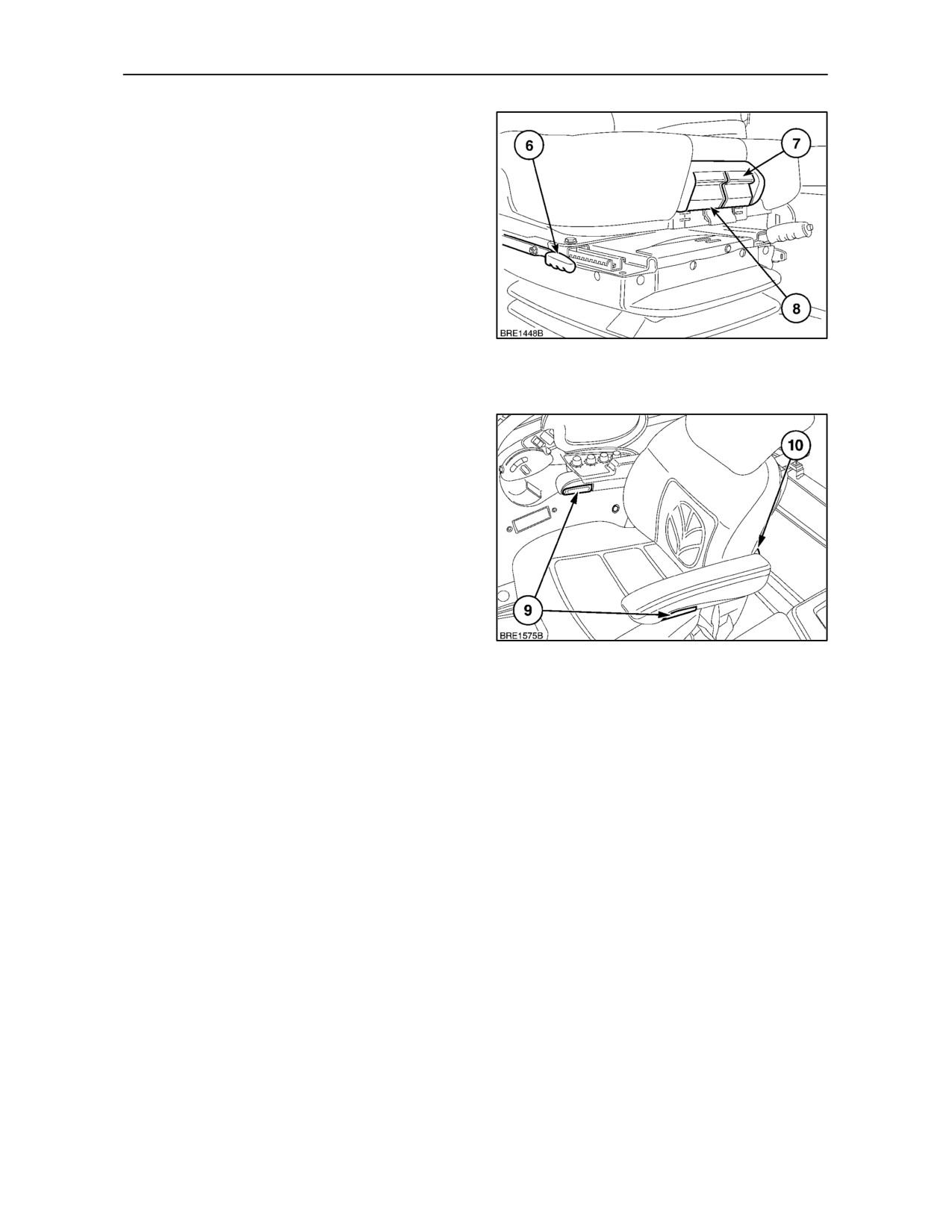
2--29
SECTION 2 -- CONTROLS, INSTRUMENTS AND OPERATION
Lift the travel adjustment lever (6) and move the seat
forward or backward, as required. The seat will lock
in position when the lever is released.
For optimum comfort, the seat cushion may be
adjusted for height and reach.
To move the seat cushion forwards or rearwards, pull
up the catch (8), grasp the cushion and move to the
desired position. Release the catch to lock.
To adjust the height, lift and hold the release catch (7)
and then pull up or push down on the front of the seat
cushion. Release the catch to lock. Cushion
52
adjustments are most easily achieved with the
operator out of the seat.
The adjusters (9) on the underside of the armrests
may be turned to alter the angle of the armrests. Turn
them clockwise to raise the front of the armrests, turn
anti-clockwise to lower. Both armrests may be raised
to the vertical position if required.
The seat has a built-in lumbar support actuated by
handwheel (10) and on the left-hand side of the
backrest. Turn the wheel clockwise to increase
lumbar support or anti-clockwise to decrease.
To adjust the height of the upper back support pad on
top of the backrest, grasp the pad and raise or lower
as desired. The pad has a number of positions in
53
which it will lock. Slowly move the pad until a faint
’click’ is heard, the pad will now remain in this
position.
A storage pouch is provided on the back of the seat.
2--30
SECTION 2 -- CONTROLS, INSTRUMENTS AND OPERATION
SEAT BELT AND OPERATOR PRESENCE
SWITCH (where fitted)
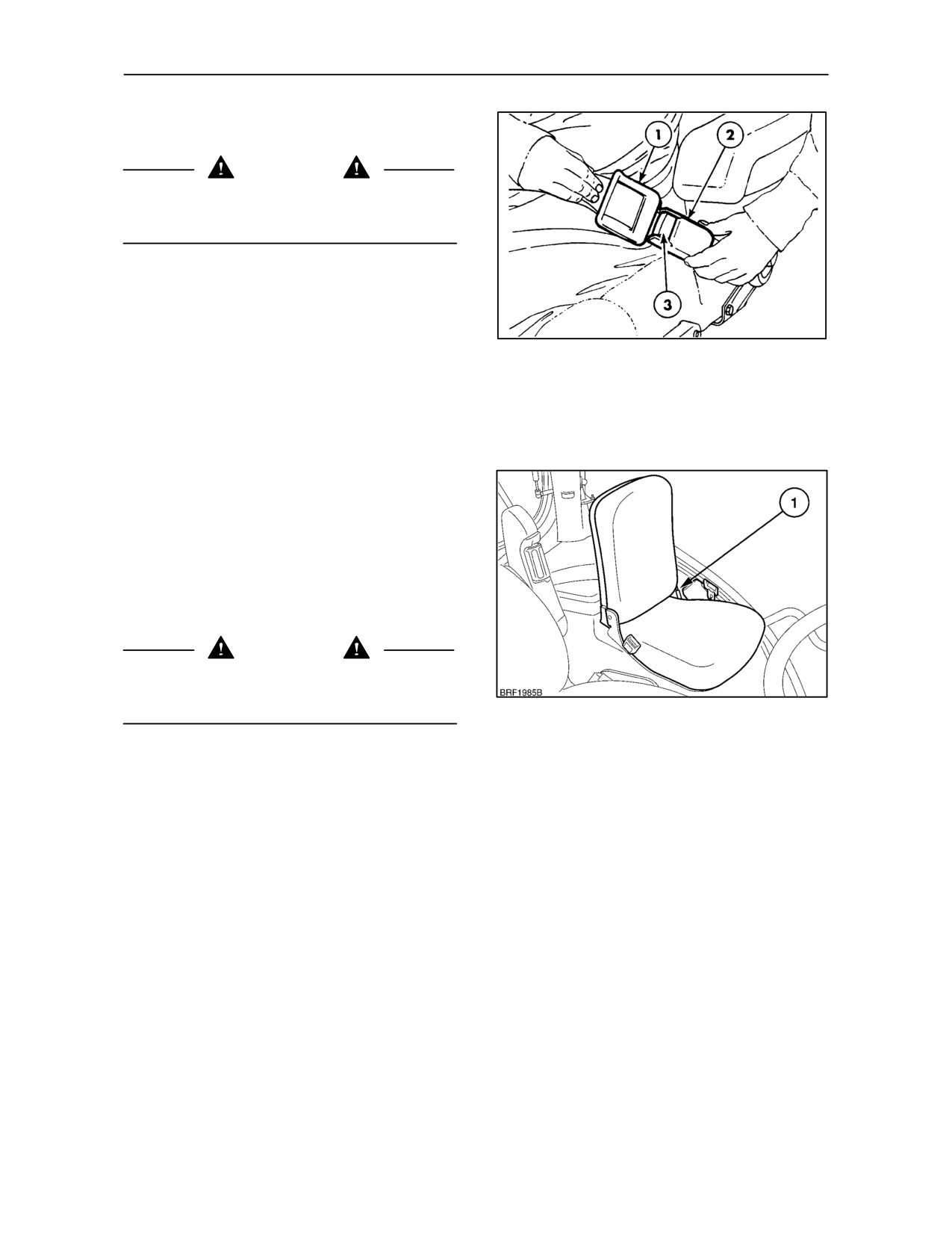
WARNING
Always use the seat belt with a safety cab or ROPS
frame installed. Do not use a seat belt if the tractor
is not equipped with a safety cab or ROPS.
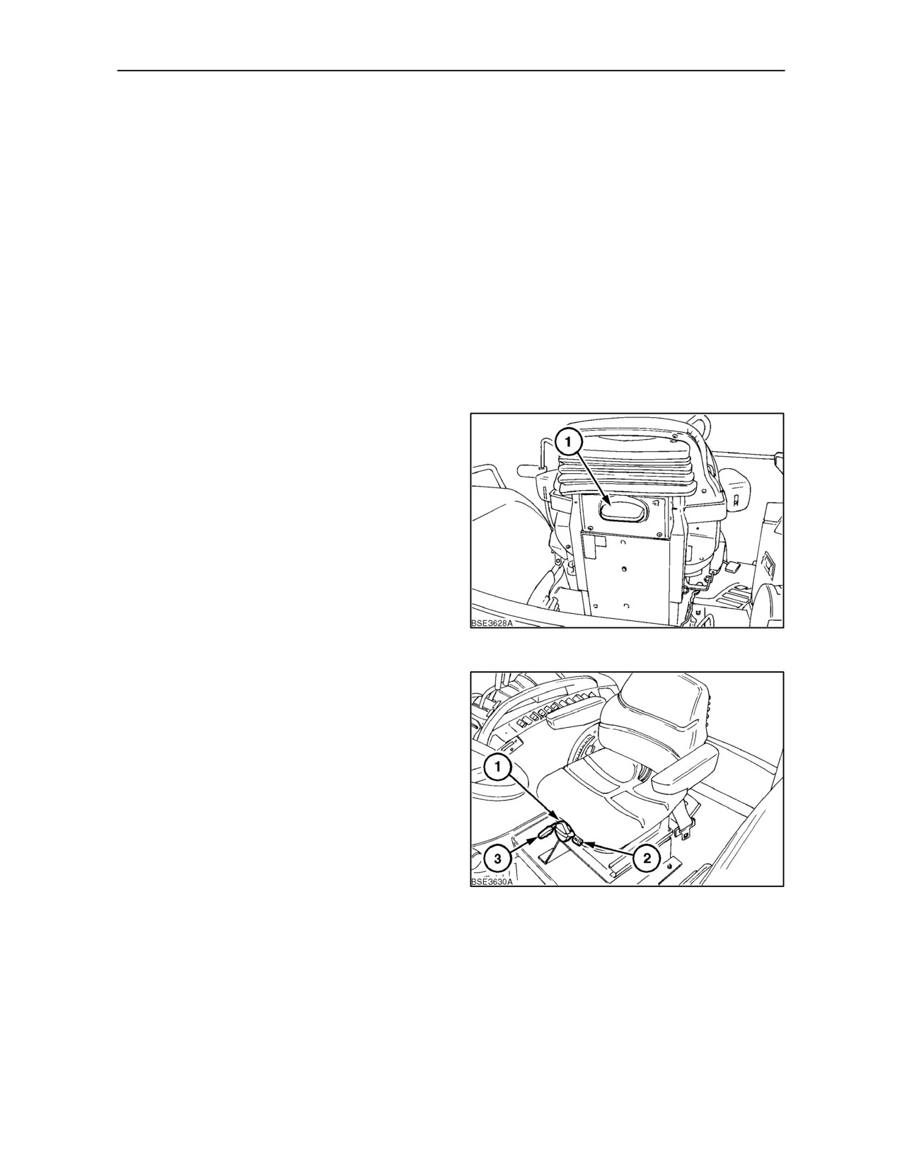
To fasten the belt, pull the belt from the reel and push
the tongue (1) into the buckle end (2) until a ‘click’
indicates it is properly engaged. Press the red
release button (3) on the buckle and remove the
tongue from the buckle.
54
The operator presence switch, installed beneath the
seat, is connected to an audible alarm which will
sound if the operator leaves the seat with the P.T.O.
engaged.
INSTRUCTIONAL SEAT
(where fitted)
A folding instructional seat is available where local
legislation permits. To raise the seat backrest, lift to
the upright position. The seat will be retained in the
upright position by the gas strut
(1). When not
required fold the upper part of the seat down to reveal
the drinks holder.
WARNING
Always use the seat belt with a safety cab or ROPS
frame installed. Do not use a seat belt if the tractor
is not equipped with a safety cab or ROPS.
55
IMPORTANT: The fold down seat is fitted for
operator training or instructional purposes only, it is
not intended for passenger conveyance.
Passengers should not be carried in the cab at any
time.
2--31
SECTION 2 -- CONTROLS, INSTRUMENTS AND OPERATION
HAND BRAKE, THROTTLE AND FOOT
PEDALS
Handbrake
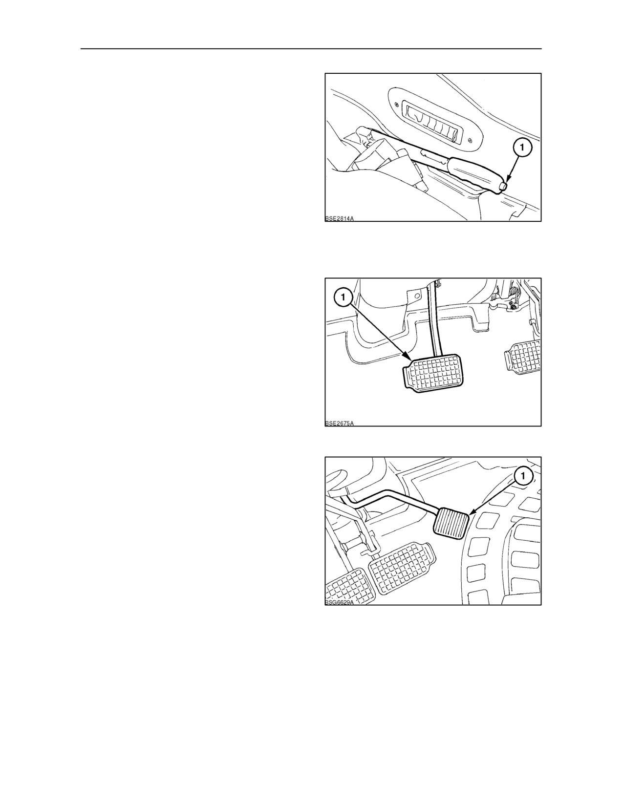
A conventional handbrake lever is installed to the left
of the driver’s seat.
To apply the handbrake, pull the lever up. A warning
light will illuminate in the instrument panel when the
handbrake is applied. To release, ease the lever up
further, depress the button (1) on the end and lower
the lever fully.
56
IMPORTANT: Ensure that the handbrake is fully
released before driving off.
Clutch/Inching Pedal
When the clutch pedal (1) is depressed the drive
between the engine and transmission will be dis-
engaged. Use the pedal to transfer engine power
smoothly to the driving wheels when moving off from
a standstill. See
‘TRANSMISSION’ later in this
section for further details.
NOTE: To avoid premature wear, do not use the
clutch pedal as a footrest.
57
Foot Throttle
The foot throttle (1) may be used independently of
the hand throttle to control the speed of the tractor.
It isrecommendedthat youuse thefoot throttlewhen
driving on the highway.
NOTE: When the foot throttle is released, engine
speed will reduce to the level set by the hand throttle.
When using the foot throttle, set the hand throttle to
the minimum speed position (lever fully rearward).
58
2--32
SECTION 2 -- CONTROLS, INSTRUMENTS AND OPERATION
Hand Throttle
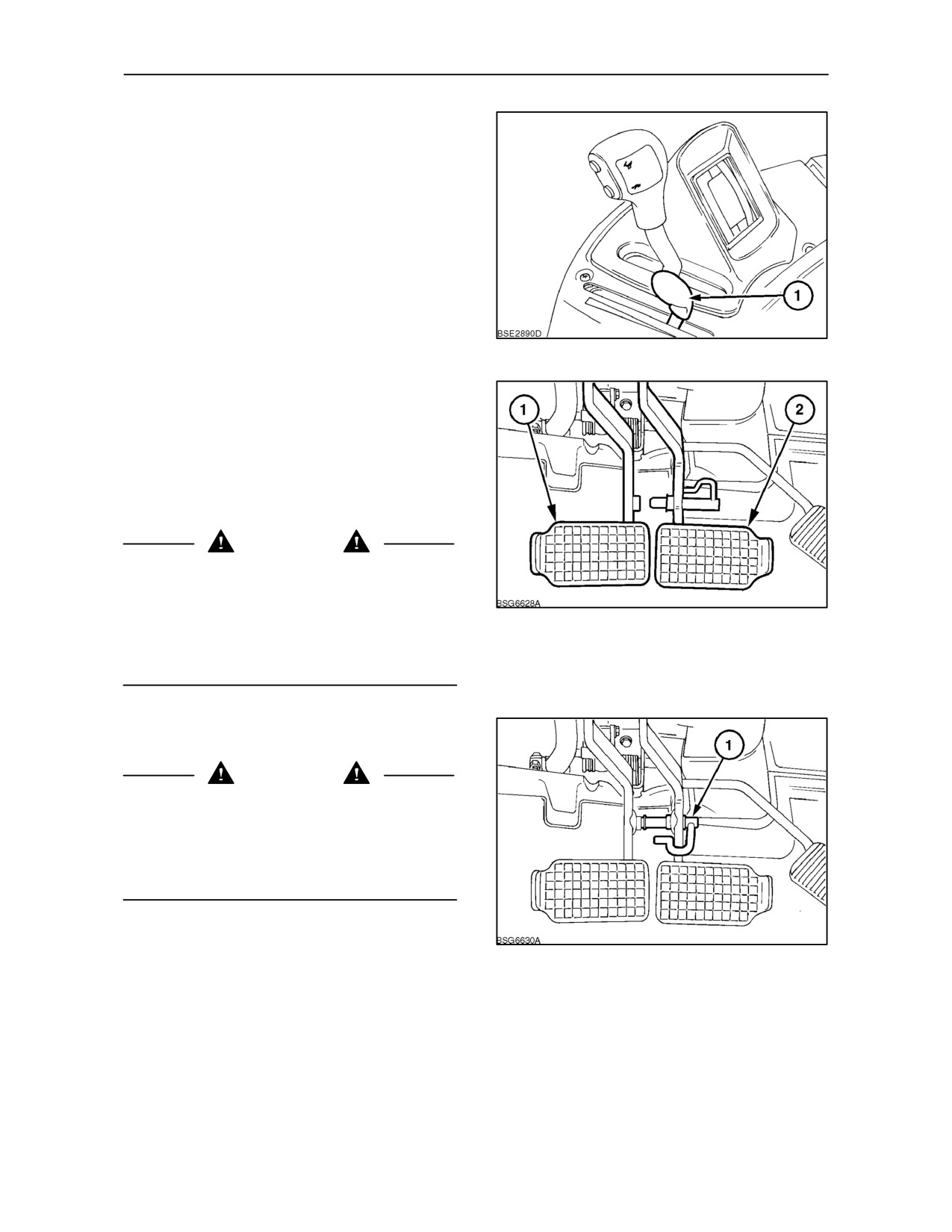
The hand throttle (1) may be used independently of
the foot throttle to control the speed of the tractor.
Move the throttle lever forward to increase engine
speed.
IMPORTANT: Always return the hand throttle to the
idle position when using the foot throttle for road
transport applications.
59
Footbrakes
The brakes are actuated by the two footpedals (1)
and (2). When operating in the field they may be
unlocked and operated independently, to aid turning
in confined spaces. When independent braking is not
required, ensure both pedals are locked together to
provide normal braking.
WARNING
On four wheel drive tractors the drive tothe front axle
is automatically engaged at speeds above 8.5 km/h
(4 MPH) when the brakes are applied to provide four
wheel braking. Owners should be aware of the
60
effectiveness of four wheel braking which greatly
enhances braking performance. Appropriate care
should be exercised during heavy braking.
IMPORTANT: Hydraulic trailer brakes will only
operate when both brakes are applied.
WARNING
For your safety, always lock the brake pedals
together when travelling at transport speeds or if a
hydraulically braked trailer is attached to the tractor.
To lock the pedals together, engage the locking pin
in the right pedal and swivel the latch (1), over the left
pedal support to lock, as shown.
61
2--33
SECTION 2 -- CONTROLS, INSTRUMENTS AND OPERATION
INSTRUMENT CONSOLE
The following text describes the use of the various
switches and controls, etc., mounted on the
instrument console and steering column.
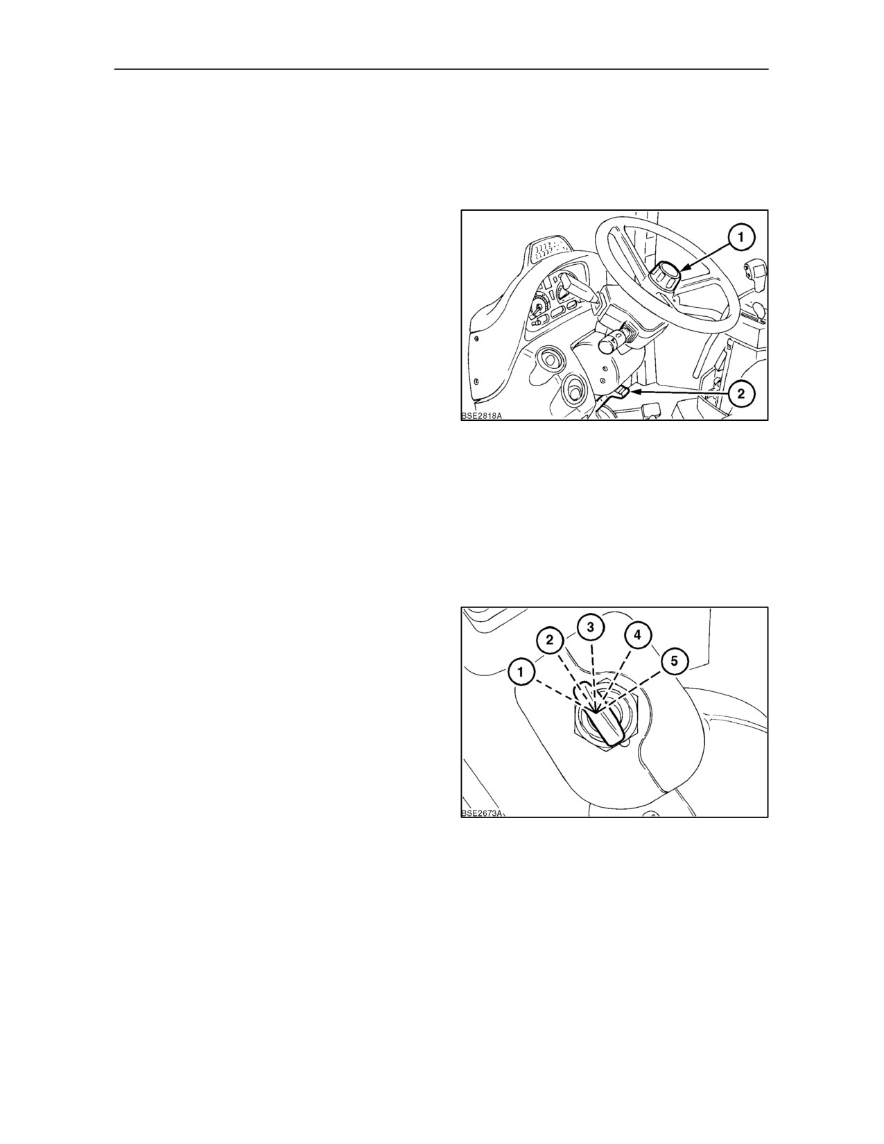
Steering Column Tilt Adjustment
The steering column on your tractor may be tilted and
telescoped. Pull the end of the clamp lever (2) up
(toward you). Move the steering column/wheel to the
most convenient position and return the clamp lever
to the fully down position to lock the steering column
assembly.
Height Adjustment (where fitted)
To alter the steering column height, loosen the centre
boss
(1) on the steering wheel by turning
anti--clockwise. Move the steering wheel to the most
62
covenient position and re--tighten the centre boss.
IMPORTANT: Your tractor is equipped with
hydrostatic power steering. Never hold the steering
wheel at full left or right lock (wheels against the
steering stops) for more than 10 seconds or for more
than a total of 10 seconds in any one minute. Failure
to observe this precaution may result in damage to
steering system components.
Key-start Switch
The key-start switch activates the grid heater cold
start device, accessories and the starting motor. See
‘Starting the Engine’ in Section 3.
63
2--34
SECTION 2 -- CONTROLS, INSTRUMENTS AND OPERATION
Multi-function Switch
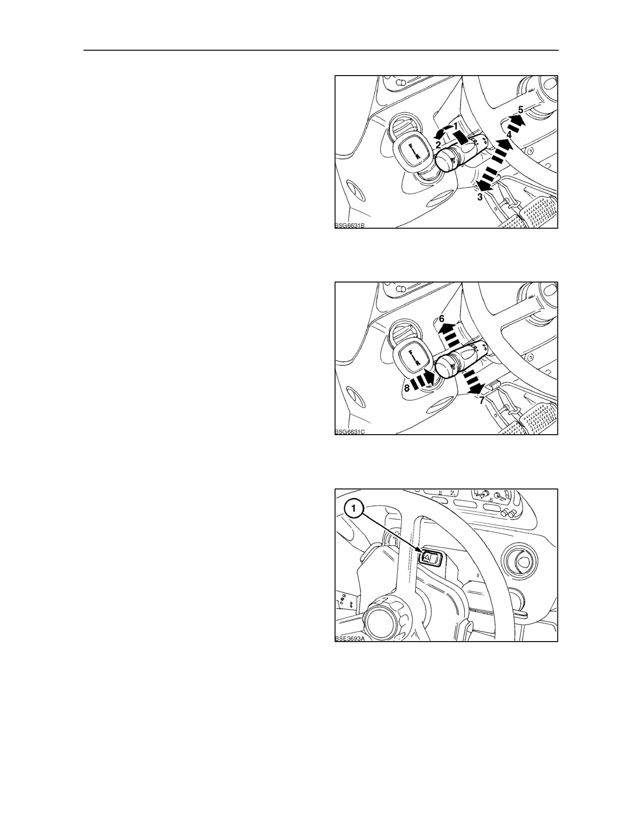
The stalk-type switch is mounted on the left-hand
side of the steering column. The switch controls the
tractor lights, horn and turn signals.
The centre of the stalk switch rotates. With reference
to Figure 64, turn the switch away from you, to
position 1, to turn on the instrument and position
lights. Turn the switch to position 2 to select the
headlights.
With the headlights on, push the stalk away from you,
position 3, to change from dipped to high beam. Pull
the stalk toward you, position 4, to change back to
64
dipped beam. With high beam selected, the blue
indicator light on the instrument panel is illuminated.
With the headlights off, pull the stalk towards you,
position
5, against spring pressure, to flash the
headlight high beam. The stalk will return to the
central position when released.
Move the stalk to position 6 to operate the right turn
signals, position 7 will activate the left turn signals.
Indicator lights on the instrument panel will also flash
when the turn signals are actuated. A warning buzzer
will sound if the indicators are not cancelled within 20
seconds.
NOTE: The turn signals will only operate with the
key-start switch turned on.
65
Press in the end of the stalk, position 8, to sound the
horn.
Hazard Warning Lights Switch
Press the left-hand side of the switch (1) to operate
all the turn signals simultaneously. The switch will
flash with the turn signals.
66
2--35
SECTION 2 -- CONTROLS, INSTRUMENTS AND OPERATION
Windscreen Wipe/Wash Control
(tractors with cab only)
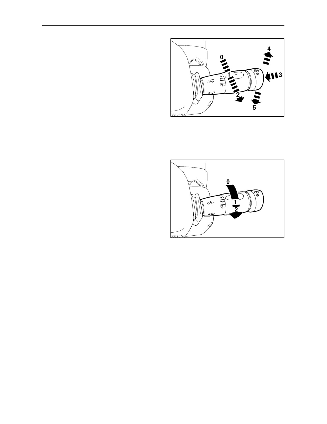
The stalk-type control on the right-hand side of the
steering column controls the front and rear screen
wipe and wash functions.
With the key-start switch on, move the stalk
rearward, to position
1 and the front wiper will
operate at the slower of the two wiper speeds, move
to position 2 for the faster speed. Press in the end of
the stalk, position 3, to operate the electric screen
wash.
67
From the centre
’off’ position move the stalk
downward to position 5 for intermittent front wipe,
move the stalk upward against spring pressure for
single sweep operation, position 4. On release, the
switch will return to the off position.
To operate the rear screen wiper, rotate the centre
collar anti--clockwise to position 1 for intermittent
rear wipe and to position 2 for rear screen wash. The
switch will return automatically to the intermittent
mode when released.
NOTE: Windscreen washer jets are mounted in the
cab frame, immediately beneath the roof. Insert a pin
into the jet nozzle to adjust the angle of the jet.
68
2--36
SECTION 2 -- CONTROLS, INSTRUMENTS AND OPERATION
ANALOGUE/DIGITAL INSTRUMENTATION
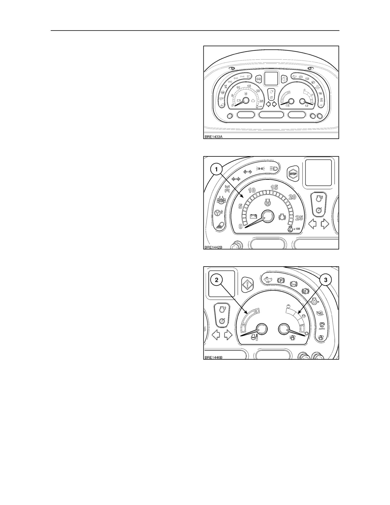
The instrument panel consists of three analogue
gauges , three liquid crystal displays (LCD’s) and a
dot matrix display (DMD).
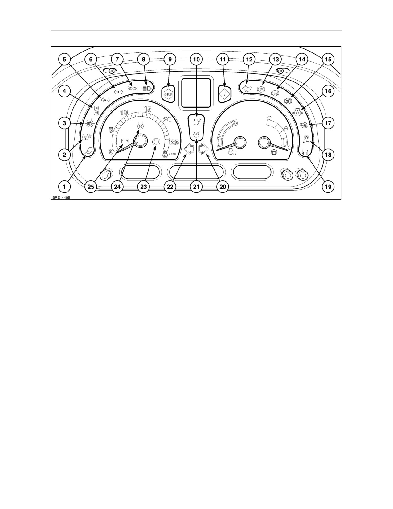
In addition to the gauges and LCD displays there are
25
coloured lights providing other operating
information or warning of system malfunction.
The lower left button on the instrument panel controls
the intensity of back lighting for the LCD’s and dot
matrix displays, the two right--hand buttons adjust
the digital clock.
69
GAUGES
Engine Tachometer
The tachometer (1) indicates engine revolutions per
minute. Each division on the scale represents 100
rev/min., therefore with the needle indicating ‘20’ the
engine is running at 2000 rev/min.
70
Engine Coolant Temperature Gauge
The temperature gauge
(2)
indicates the
temperature of the engine coolant. If the needle
enters the upper (red) section of the gauge while the
engine is running, stop the engine and investigate
the cause.
Fuel Level Gauge
The gauge (3) indicates the level of fuel in the tank
and is only operative with the key-start switch turned
on. See Section 8 for fuel capacities.
71
2--37
SECTION 2 -- CONTROLS, INSTRUMENTS AND OPERATION
72
INDICATOR AND WARNING LIGHTS
The coloured indicator lights provide operating
4. Four wheel drive -- Light will illuminate when the
information or give warning of system malfunction.
drive to the front wheels is engaged.
Illumination of a warning light may be accompanied
5. Trailer turn signal
-- Light will flash with
by an audible alarm. Refer to Alarm Functions on
tractor/trailer turn signals when a second trailer
page 2--46
is attached.
Indicator and Warning Lights
6. Trailer turn signal
-- Light will flash with
tractor/trailer turn signals when a trailer is
NOTE: All indicator and warning lights will illuminate
attached
for a short period at
’key--on’ as the electrical
systems carry out a self diagnostic check.
7. Parking lights -- Light will illuminate when the
tractor lights are switched on.
1. Not used.
8. Headlight high beam -- Light will illuminate when
the tractor lights are switched to high beam.
2. Fast Steer -- Light will illuminate when fast steer
function is activated.
9. Red Stop light -- If Stop light comes on stop the
tractor immediately and investigate the cause. A
3. Differential lock -- Light will illuminate when the
warning symbol will appear in the Dot Matrix
differential lock is engaged.
Display to confirm the location of the fault.
2--38
SECTION 2 -- CONTROLS, INSTRUMENTS AND OPERATION
73
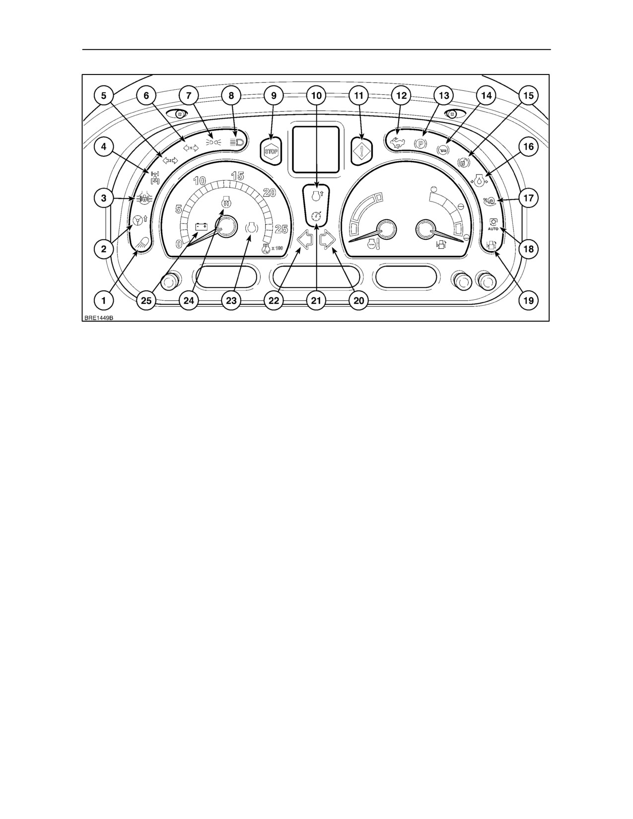
Indicator and Warning Lights (continued)
10. Not used.
14. Trailer brake pressure (Italy only) -- Light will
illuminate to indicate that hydraulic oil pressure
11. Amber Warning light -- Illumination of this light will
to the trailer brake circuit is low. Stop the tractor
be accompanied by a warning symbol in the Dot
and investigate the cause.
Matrix Display. Stop the tractor and investigate
the cause.
15. Brake pedals not latched -- Light will illuminate to
show when pedal latch is unlocked (Japan only).
12. Direct drive indicator
(Dual Command
transmission only)
-- Light will illuminate to
16. Engine oil pressure low
-- Steady light
indicate transmission is in direct drive.
accompanied by the Red Stop light will indicate
low engine oil pressure. Stop the engine and
13. Parking brake -- Light will flash with key-start
investigate the cause.
switch on and parking brake applied. If the
key-start switch is turned off and the parking
17. Creeper gears
-- Light will illuminate when
brake not applied, or the operator leaves the seat
creeper gears are engaged.
without applying the handbrake, a warning
buzzer will sound for approximately 10 seconds
or until the handbrake is applied.
2--39
SECTION 2 -- CONTROLS, INSTRUMENTS AND OPERATION
74
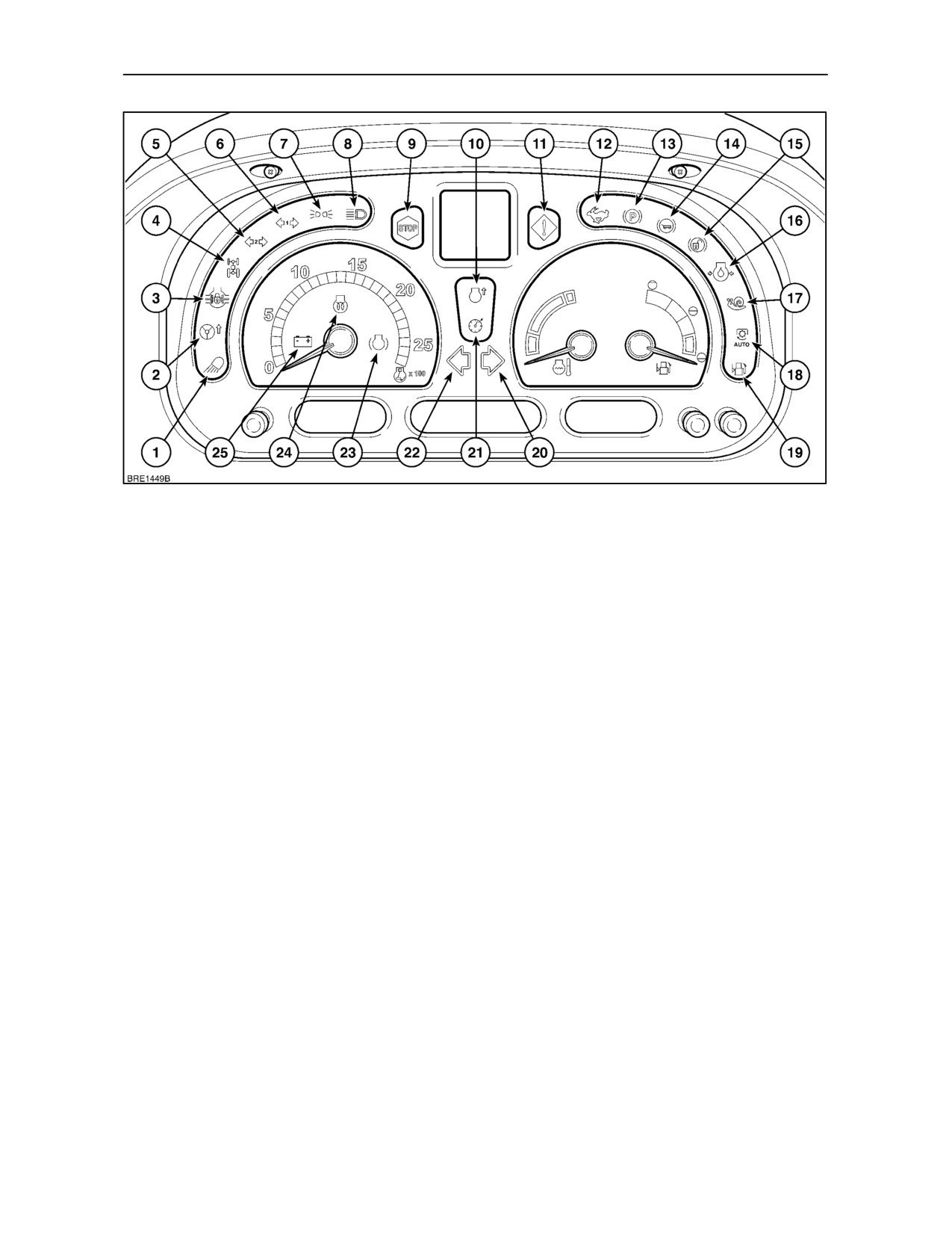
Indicator and Warning Lights (continued)
18. Auto P.T.O. function -- The light will illuminate
21. Not used.
when the Auto P.T.O. function is enabled. Each
22. Left turn indicator -- Light will flash with tractor
time the implement is raised with Auto P.T.O.
left-hand turn signal. Intermittent alarm will
activated, the light will flash. When the
sound if indicator is not cancelled after
20
implement is lowered into work the light will
seconds (5 minutes with tractor stationary).
cease to flash and become steady.
23. Not used.
19. Fuel level low -- Light will be illuminated when the
tractor requires re--fuelling. See Section 8 for fuel
24. Cold start device -- Light will illuminate when the
capacities.
grid heater is activated using the key--start
switch.
20. Right turn indicator -- Light will flash with tractor
right-hand turn signal. Intermittent alarm will
25. Alternator
-- Light continuously illuminated
sound if indicator is not cancelled after
20
indicates that the alternator is not charging the
seconds (tractor moving) or 5 minutes (tractor
battery.
Stationary).
2--40
SECTION 2 -- CONTROLS, INSTRUMENTS AND OPERATION
LIQUID CRYSTAL DISPLAYS
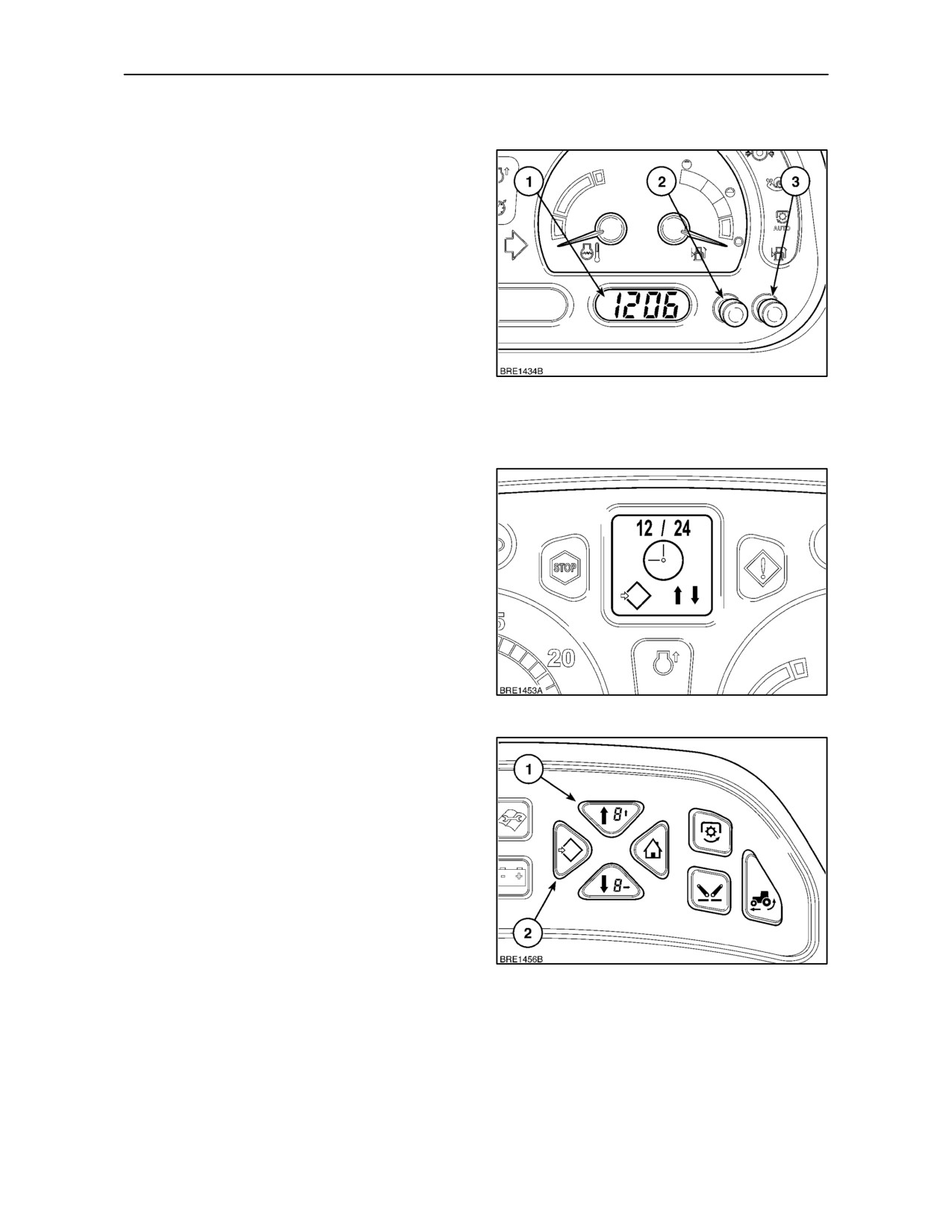
Clock
A digital clock (1) is installed on the right--hand side
of the instrument panel.
To adjust the time display turn the key--start on,
depress and hold the Hour or Minute button until the
read out starts to Flash. To advance the hour,
depress the ’H’ button (2). Each time the button is
depressed the time will advance by
1
hour.
Alternatively, hold in the button and the display will
advance automatically. Release the button when the
time setting is correct.
75
Repeat the procedure using the ’M’ button (3) for the
minute display. To memorise the setting do not touch
either button for 10 seconds.
Changing the display with ’H’ and ’M’ buttons
The clock is set at the factory to display a 12 hour
reading. To change to a 24 hour reading, depress and
hold both ’H’ and ’M’ buttons with the key--start off.
Turn the key--start on and continue to hold both
buttons for three seconds, the clock will change to
show a 24 hour display. Repeat the procedure to
change back to a 12 hour reading. Turn the key--start
off to store the setting.
76
Changing the display with Enhanced Keypad
(where fitted)
With the key--start in the ON position, depress and
hold the Menu/Enter key (2) for 3 seconds. The DMD
will read SETUP MENU, this will change to CAL after
2 seconds. Using the Menu Up key (1), scroll through
the menu until the clock symbol appears in the
display accompanied by 12 / 24, Figure 76.
Depress the Menu/Enter key again and the display
will change to show an arrow pointing to 12 or 24.
Using the Menu Up/Down keys move the arrow up or
down to the setting required and then depress the
77
Menu/Enter key to save and return to the main menu.
2--41
SECTION 2 -- CONTROLS, INSTRUMENTS AND OPERATION
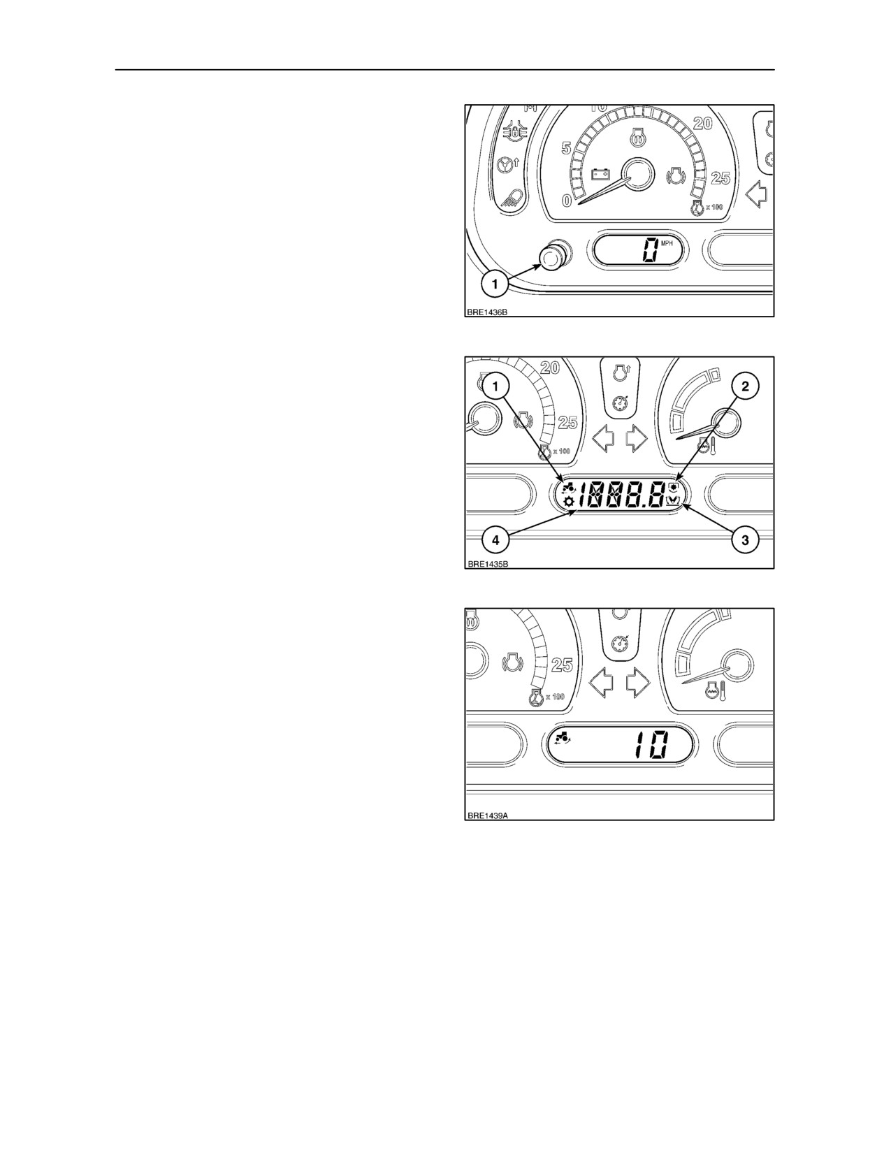
Dimming Control
The brightness of the liquid crystal (LCD) and dot
matrix displays (DMD) may be varied by using the
dimming control button (1). Momentarily depressing
the button will alter the backlighting in steps. Depress
and hold the button to cycle through the full range of
backlighting from low to high intensity. Release the
button when the required setting is obtained.
78
Centre LCD
The information displayed in the centre LCD, will vary
depending on tractor specification. Use the CAL/SEL
switch or Enhanced Keypad (where fitted) to toggle
between the displays.
The following information may be displayed in the
centre LCD.
1. Rear wheel slip (with radar option only)
2. Power Take Off speed (front or rear)
3.
3--point hitch position (front or rear)
79
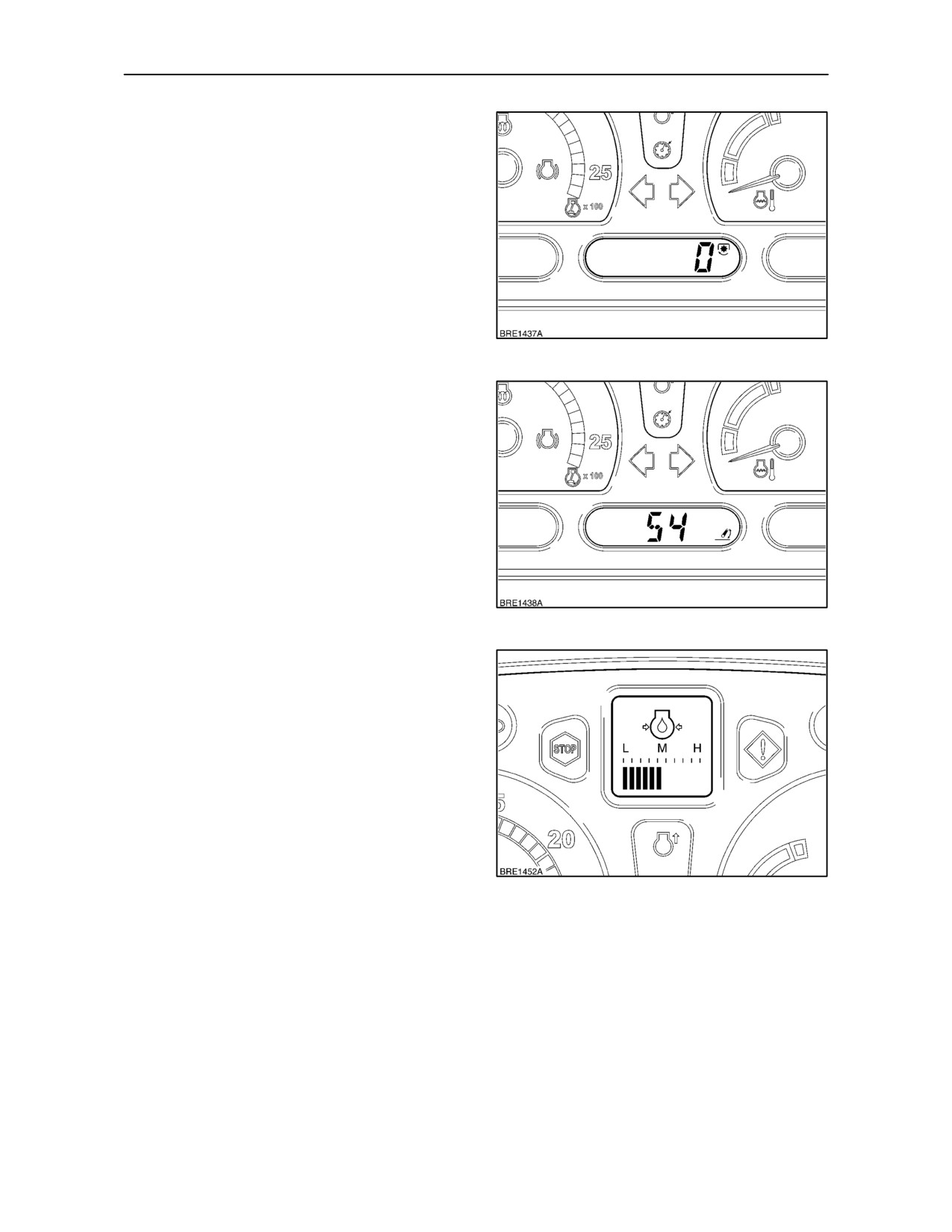
Rear Wheel Slip
If yourtractor isequipped withoptional groundspeed
radar, the percentage (%) of rear wheel slip may be
displayed. The slip figure is calculated from
information provided by the transmission speed
sensor (theoretical ground speed) and the radar (true
ground speed).
80
2--42
SECTION 2 -- CONTROLS, INSTRUMENTS AND OPERATION
Power Take Off Speed
When operating the rear Power Take Off the display
may be used to monitor the output shaft speed. Use
the CAL/SEL button or Enhanced Keypad (where
fitted), to select either rear P.T.O. speed or front
P.T.O. speed (where fitted).
81
3--Point Hitch Position
If your tractor is equipped with Electronic Draft
Control (EDC) the display may be used to show the
position of the 3--point hitch (and implement) by
means of numbers ranging from ’0’ (fully lowered
position) to ’100’ (maximum lift height).
When a front hitch is installed, the display may be
used to show the height of the front lift arms. ’0’ will
represent the fully lowered position,
’100’ the
maximum lift height.
82
DOT MATRIX DISPLAY
A number of tractor operating and set--up functions
may be shown in the Dot Matrix Display (DMD). To
select a function use the CAL/SEL button or the
Enhanced Keypad (where fitted). A symbol will
appear to confirm the function selected.
NOTE: See page NO TAG for an explanation of
warning and advisory symbols.
If an error occurs in the instrument panel or tractor
systems circuits, a malfunction warning symbol will
appear in this display accompanied by an error code.
83
Consult your authorised dealer.
2--43
SECTION 2 -- CONTROLS, INSTRUMENTS AND OPERATION
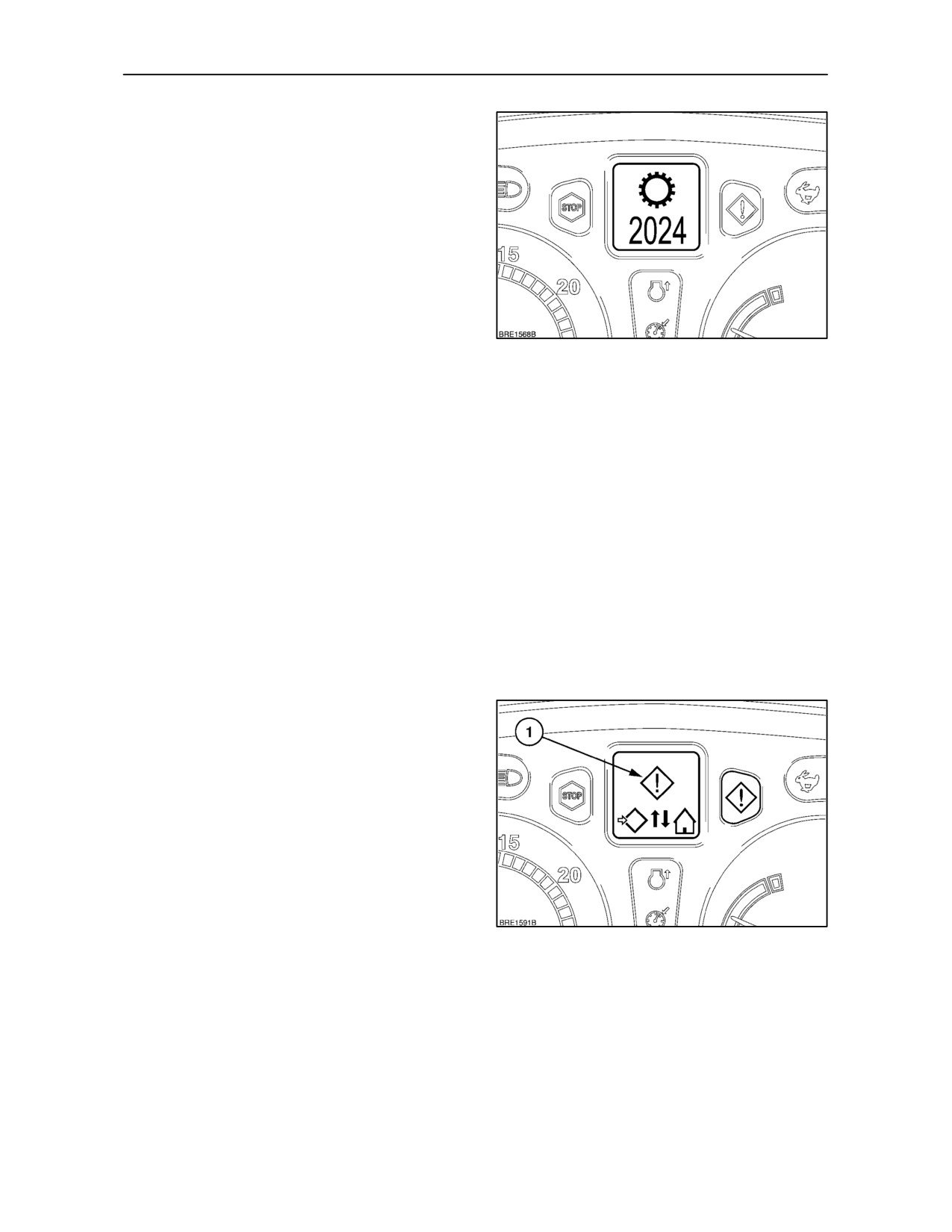
Error Codes
The advanced electronics on your tractor are able to
detect a malfunction or error occuring in key areas
such as engine, transmission, electrical and
hydraulic systems. Should a malfunction or error
occur, a symbol will appear in the DMD with a four
digit error code. This may be accompanied by the
illumination of a warning light and an audible alarm
depending on the severity of the fault. Consult your
authorised dealer.
Active and Non Active Warnings
84
In addition to the error codes previously described,
there are a number warning symbols that may
appear in the Dot Matrix Display. These symbols will
be accompanied by either a Red (critical) or Amber
(non--critical) warning light.
Critical symbols appearing with a Red warning light
will remain permanently displayed until the tractor is
stopped and the fault rectified.
Non critical symbols accompanied by the Amber light
will be displayed for five seconds before the DMD
defaults to the symbol previously shown. The amber
warning light will continue to illuminate.
By using the CAL/SEL button, or the Enhanced
Keypad where fitted, active warnings that are not
permanently displayed may be recalled.
Using the CAL/SEL button
• Depress and hold the CAL/SEL button for three
seconds to enter SETUP MENU, after two
seconds the display will change to CAL. Using
the clock set buttons H and M to toggle the
display, select the the active warning symbol (1),
Figure 85.
• Depress the CAL/SEL button and the active
symbol will be replaced with a symbol
corresponding to the fault detected.
• If more than one warning symbol has been
85
stored, the display will cycle through each one in
turn. After the fault symbols have been
displayed, the screen will default back to the
active warning symbol.
• Momentarily depress the dimming button to exit
the display.
2--44
SECTION 2 -- CONTROLS, INSTRUMENTS AND OPERATION
Using the Enhanced Keypad
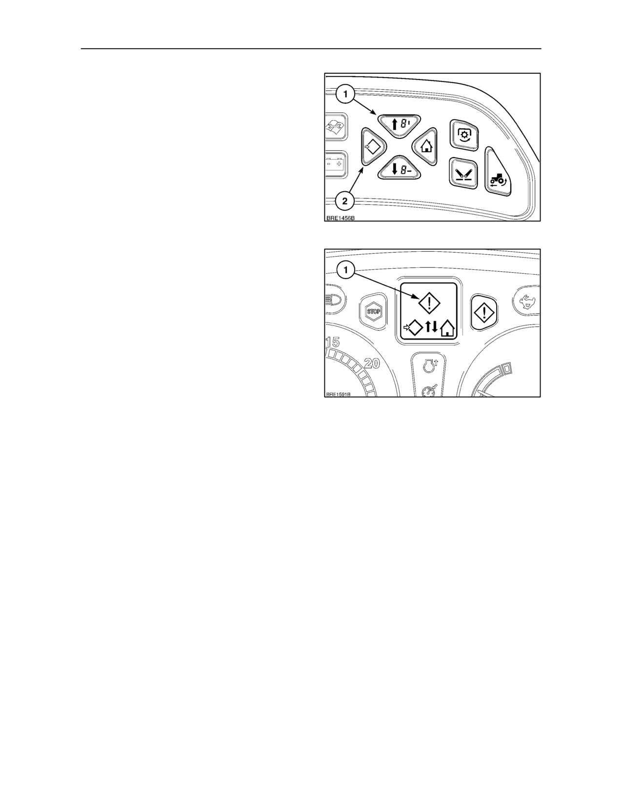
• With the key--start in the ON position, depress
and hold the Menu/Enter key (2) for 3 seconds.
The DMD will read SETUP MENU, this will
change to CAL after 2 seconds. Using the Menu
Up key (1), scroll through the menu until the
active warning symbol
(1) Figure 87, is
displayed.
• By momentarily depressing the Menu/Enter key
again, the active symbol will be replaced with a
symbol corresponding to the fault detected.
86
• If more than one non--active symbol has been
stored, the display will cycle through each one in
turn. After the fault symbols have been
displayed, the screen will default back to the
active warning symbol.
Touch the Exit/Cancel key to exit and return to the
original display.
87
2--45
SECTION 2 -- CONTROLS, INSTRUMENTS AND OPERATION
ALARM FUNCTIONS
Illumination of a warning light may be accompanied
Action Required
by an audible alarm. Depending on the severity of the
malfunction, an alarm will sound as follows.
A two pulse alarm will sound for 1 second to advise
the operator that a certain action is required. The
alarm will continue to be present until the operator
Critical Alarm
carries out the appropriate action or the tractor
Alarm will sound continually accompanied by the red
engine is switched off.
warning light. The tractor must be stopped
immeadiately. The alarm will sound until the fault is
General Alarm
corrected or the engine switched off.
A general alarm will sound if the operator attempts to
Non Critical Alarm
carry out an inappropriate action i.e.
driving
the
tractor with the parking brake applied.
A5secondcontinuousalarmwillbeaccompaniedby
the amber warning light. A failure or error has
occurred but the operator may continue work. The
fault should be rectified as soon as possible.
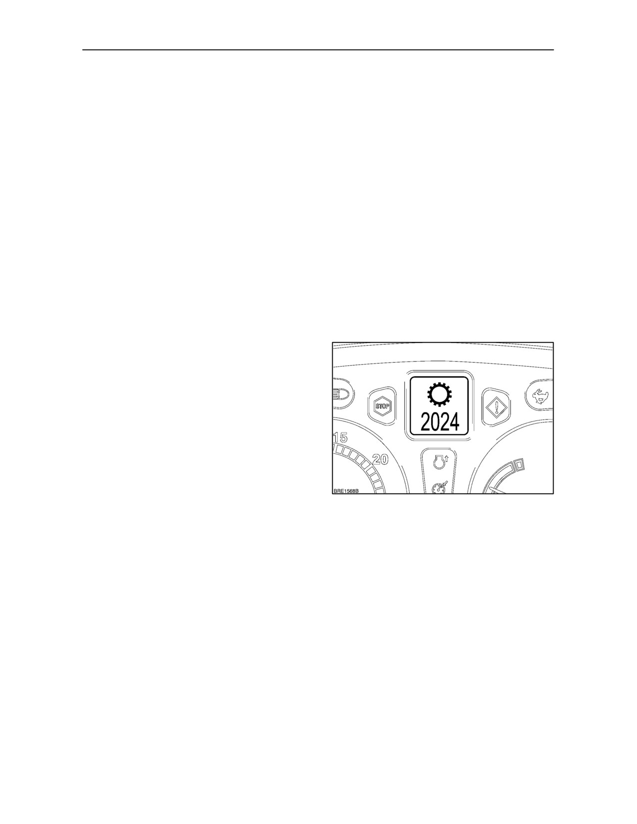
WARNING and ADVISORY SYMBOLS
There are a number of warning/advisory symbols
that may appear in the Dot Matrix Display. The
symbols can be categorised into four main groups.
1. Warning. These symbols advise of a fault that is
critical to the operation of the tractor. Stop the
tractor as soon as possible, investigate the
cause and rectify the fault.
2. Maintenance. These symbols tell the operator
there is a concern relating to the basic functions
of the tractor, ie. low fuel, low coolant level etc.
3. System Fault. The system fault symbols relate
88
to an operational fault in one or more of the
tractors main components, either electrical or
mechanical. May be accompanied by a four digit
fault code. Consult your authorised dealer.
4. Advisory. The advisory symbols are not
detrimental to the operation of the tractor but
should not be ignored. Take appropriate action
where necessary.
2--46
SECTION 2 -- CONTROLS, INSTRUMENTS AND OPERATION
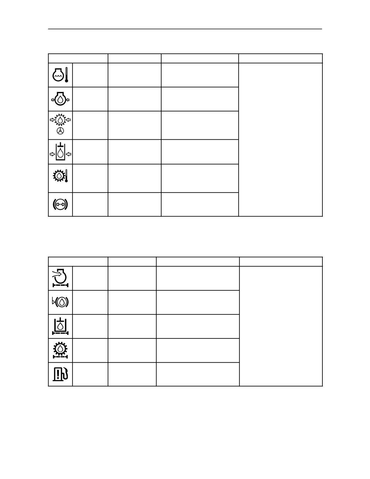
DOT MATRIX SYMBOLS -- WARNING
SYMBOL / DISPLAY
ALARM
FAULT
ACTION
Engine coolant temperature
Symbol
Critical
too high. Accompanied by
flashing
RED warning light.
Engine oil pressure low.
Symbol
Critical
Accompanied by RED
flashing
warning light.
These symbols advise of a
Transmission/power steering
fault that is critical to the
Symbol
oil pressure low.
operation of the tractor.
Critical
flashing
Accompanied by RED
warning light.
Stop the tractor as soon as
possible, investigate the cause
Hydraulic system charge
and rectify the fault.
Symbol
Critical
pressure low. Accompanied
flashing
by RED warning light.
If the fault cannot be easily
rectified, consult your
Transmission oil
Non critical
authorised dealer.
Symbol
temperature too high.
(AMBER).
flashing
Accompanied by RED* or
Critical (RED).
AMBER* warning light.
Air brake pressure low.
Symbol
Non critical
Accompanied by AMBER
flashing
warning light.
* RED warning light, tractors with auto engine shut down.
*AMBER warning light, tractors without auto engine shut down.
DOT MATRIX SYMBOLS -- MAINTENANCE
SYMBOL / DISPLAY
ALARM
FAULT
ACTION
Engine air filter blocked.
Symbol
Non critical
Accompanied by AMBER
flashing
warning light.
Brake fluid level low.
These symbols advise of a
Symbol
Non critical
Accompanied by AMBER
fault that may be critical to the
flashing
warning light.
operation of the tractor.
Hydraulic oil filter blocked.
Stop the tractor as soon as
Symbol
Non critical
Accompanied by AMBER
possible, investigate the cause
flashing
warning light.
and rectify the fault.
Transmission oil filter blocked.
If the fault cannot be easily
Symbol
Non critical
Accompanied by AMBER
flashing
rectified, consult your
warning light.
authorised dealer.
Water contamination in fuel.
Symbol
Non critical
Accompanied by AMBER
flashing
warning light.
2--47
SECTION 2 -- CONTROLS, INSTRUMENTS AND OPERATION
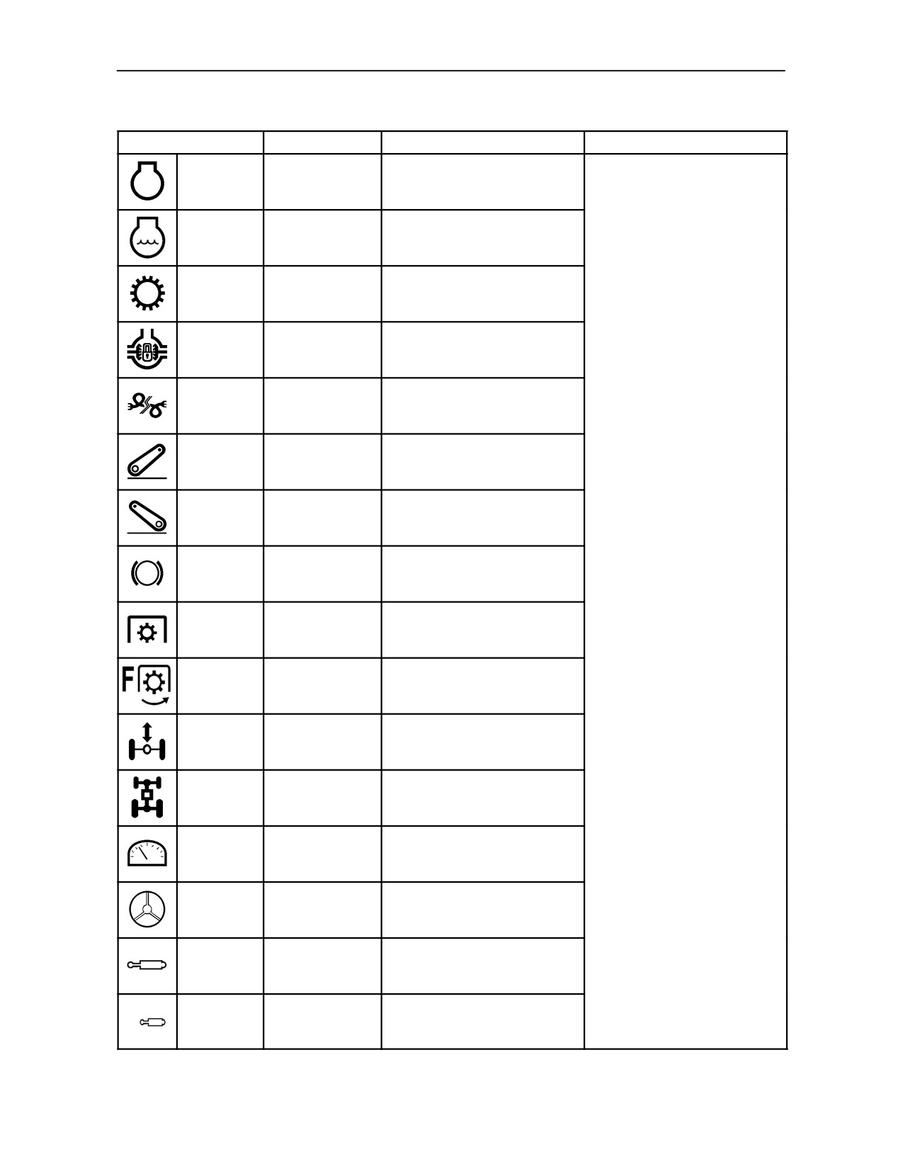
DOT MATRIX SYMBOLS -- SYSTEM FAULT
SYMBOL / DISPLAY
FAULT CODE
AREA of FAULT
ACTION
Symbol ON
3------
Engine
Symbol ON
n/a
Engine cooling system
Symbol ON
2------
Transmission
Symbol ON
7------
Differential lock
Symbol ON
n/a
CAN BUS malfunction
Symbol ON
1------
Electronic draft control
The system fault symbols
Symbol ON
9------
Front 3--point hitch
relate to an operational fault in
one or more of the tractors
main components, either
Symbol ON
n/a
Braking system
electrical, mechanical or
hydraulic.
The appearance of a fault
Symbol ON
5------
Rear P.T.O. system
symbol may be accompanied
by a four digit fault code.
Consult your authorised
Symbol ON
8------
Front P.T.O. system
dealer.
Symbol ON
10----
Front suspension
Symbol ON
6------
Front wheel drive
Instrument panel electrical
Symbol ON
14----
fault
Symbol ON
15----
Fast Steer system
Symbol ON
4------
Rear electronic remote valves
F
Symbol ON
45----
Front electronic remote valves
2--48
SECTION 2 -- CONTROLS, INSTRUMENTS AND OPERATION
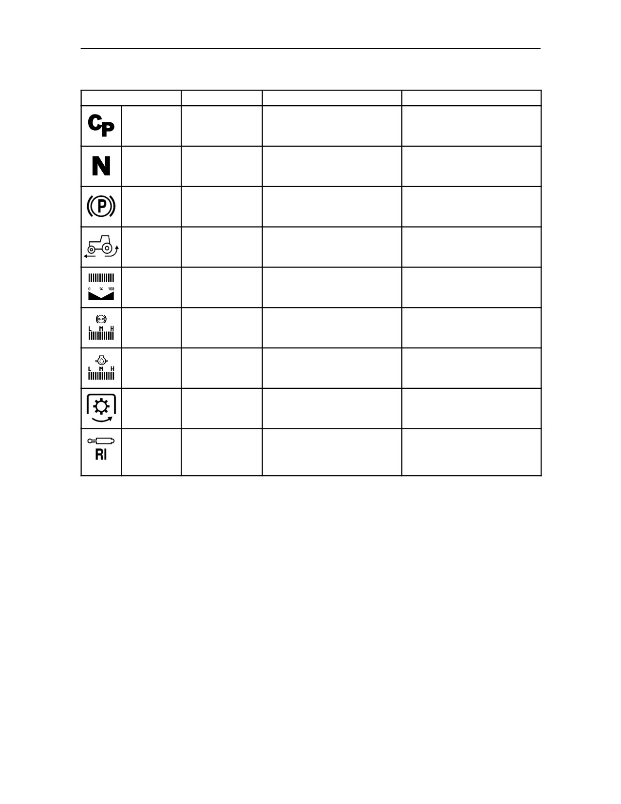
DOT MATRIX SYMBOLS -- ADVISORY
SYMBOL / DISPLAY
ALARM
CAUSE
ACTION
Symbol ON
Action required
Clutch pedal not depressed.
Cycle clutch pedal.
Symbol ON
Action required
Shuttle lever in drive.
Place shuttle lever in neutral.
Symbol ON
Action required
Parking brake applied.
Release parking brake.
Wheel slip limit exceeded.
Symbol ON
Non critical
Accompanied by AMBER
Reduce implement draft load.
warning light.
Adjust backlighting to required
Symbol ON
None
DMD backlighting level.
level.
See ’Warning’ symbols for air
Symbol ON
Critical
Air brake system pressure.
brake pressure.
See ’Warning’ symbols for
Symbol ON
Craitical
Engine oil pressure level.
engine oil pressure.
Rear P.T.O. engaged, operator
Critical or non
If accompanied by critical
Symbol ON
not present. Accompanied by
critical
alarm apply parking brake.
AMBER warning light.
EHR remote valve not
functioning, insufficient oil flow
Reduce oil flow requirements
Symbol ON
Action required
available. (May also show R2,
to other services.
R3, R4).
2--49
SECTION 2 -- CONTROLS, INSTRUMENTS AND OPERATION
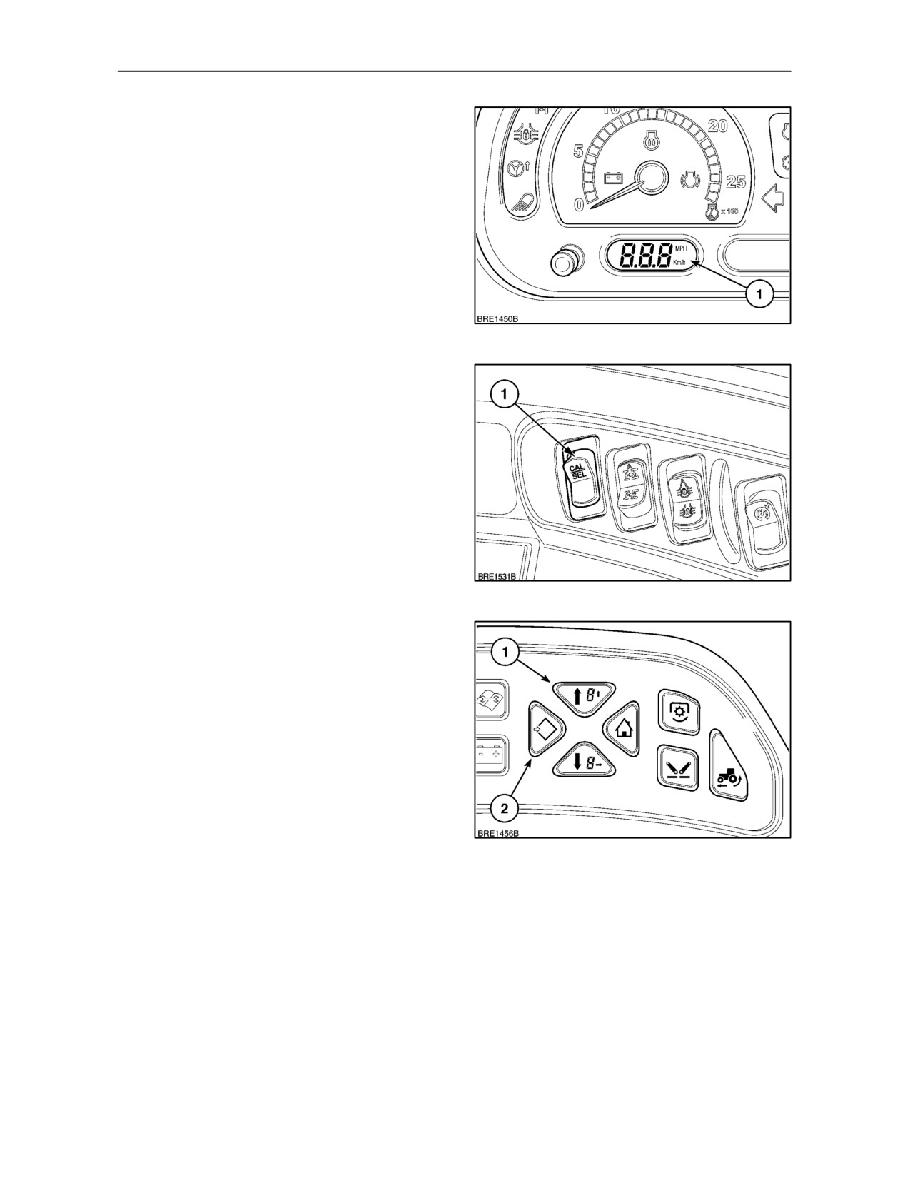
Tractor Ground Speed Display
The lower left--hand LCD provides a permanent
display of ground speed
(1) in km/h or MPH
dependent upon the country in which the tractor is to
be used. If required, the display may be changed to
read an alternate ground speed unit from that set at
the factory.
NOTE: If the tractor rear tyre size is changed, the
ground speed display may require re--calibrating to
suit the radius of the new tyre.
NOTE: Illustration shows all displays activated.
89
Changing the Ground Speed Units
Using the CAL/SEL Button
• With the key--start switch in the OFF position,
depress and hold in the CAL/SEL button (1) and
turn the key-start switch ON. The Km/h MPH
symbols will appear flashing in the display.
Release the button.
• Press the CAL/SEL button again to toggle between
Km/h and MPH. When the required ground speed
unit is displayed turn off the key--start to store the
selected speed unit in the memory.
90
Using the Enhanced Keypad
(where fitted)
• With the key--start in the ON position, depress
and hold the Menu/Enter key (2) for 3 seconds.
The DMD will read SETUP MENU, this will
change to CAL after 2 seconds. Using the Menu
Up key (1), scroll through the menu until the
Km/h MPH screen appears.
• Momentarily depress the Menu/Enter key (2)
and, using the Menu Up/Down keys, select the
required speed reading. To store the setting and
return to the main menu depress the Menu/Enter
91
key again. Depress the Exit/Cancel key to return
to the original display.
2--50
SECTION 2 -- CONTROLS, INSTRUMENTS AND OPERATION
Calibrating the Ground Speed Display
Should you wish to install alternative rear tyre
equipment that would provide a radius difference of
more than 13 mm (0.5 in), then the electronic control
module should be re--calibrated to display an
accurate ground speed figure. To re--calibrate use
one of the following methods:
IMPORTANT: If your tractor is equipped with the
optional slip control feature, then the ground speed
displayed is a true speed as sensed by a radar unit,
calibration is therefore not required.
• Ensure that the tyre pressures are correct for the
load being carried.
(See Tyre Load/Inflation
tables in Section 3 of this manual).
• Select a stretch of dry, firm, level ground
(preferably concrete) and carefully measure out
a distance of exactly 100.0 m (328 feet). Mark the
start and finish of this measured distance with a
bold chalk line.
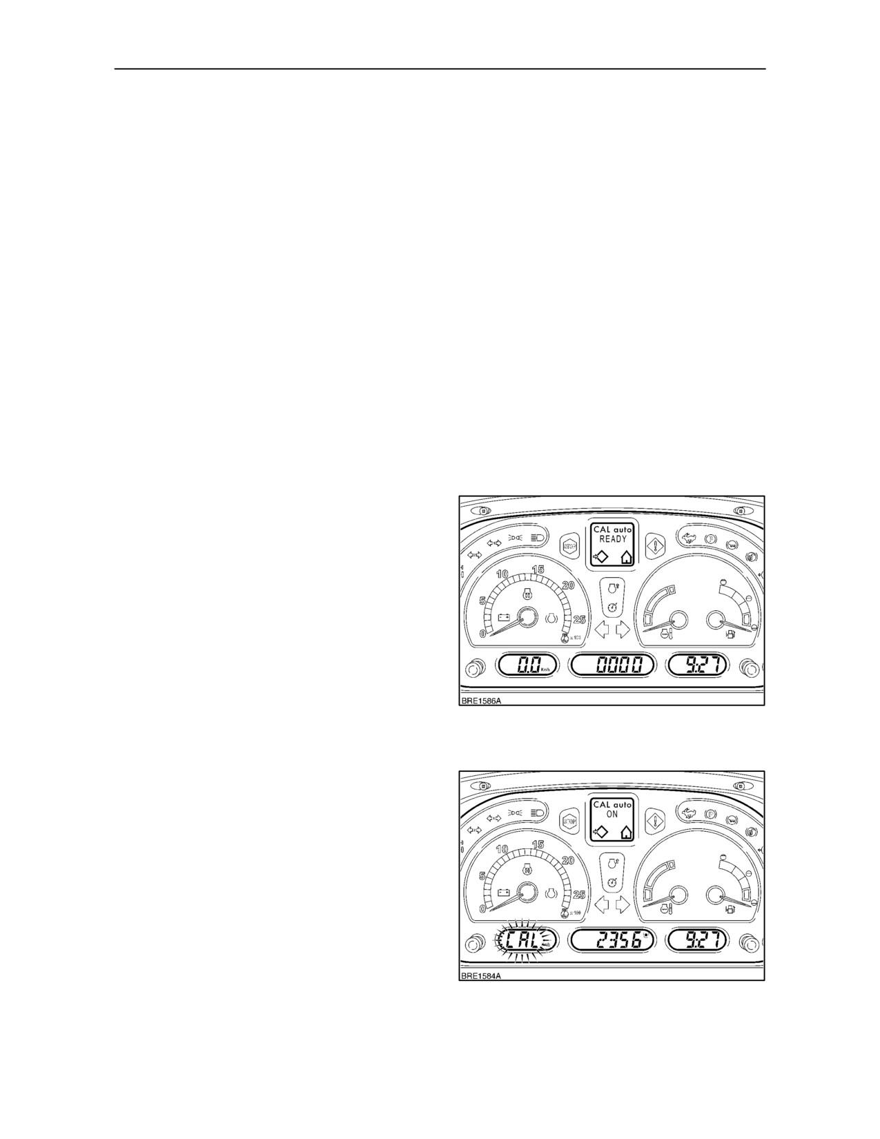
Auto Calibration with CAL/SEL Button
• Park the tractor a short distance from the start
line and, with the engine running, depress and
hold the CAL/SEL button for 3 seconds to enter
the calibration mode. SETUP_MENU will appear
in the Dot Matrix Display. After approximately
two seconds the display will change to CAL.
Depress the CAL/SEL button again to enter the
calibration mode. Using the clock Hour button
select CAL auto. Depress the CAL/SEL button
to confirm selection of CAL auto, the central
LCD display will read 0000.
NOTE: The set up procedure may be cancelled at
92
any time by depressing the LCD dimmer control
button or by turning the key--start off.
• Select a suitable transmission ratio to provide a
speed above 3 km/h (1.8 MPH) and drive up to
the start line, CAL auto READY will appear in the
display. As the centre of the front tyres passes
over the start line, press and release the
CAL/SEL button. CAL will flash in the speed
display, CAL auto ON will appear in the DMD and
the central LCD will show a four digit figure that will
increase as the tractor moves forward.
NOTE: If the calibration procedure is incorrectly
performed i.e. speed below 3 Km/h (1.8 MPH), CAL
KO will appear in the display, depress CAL/SEL to
restart sequence.
93
2--51
SECTION 2 -- CONTROLS, INSTRUMENTS AND OPERATION
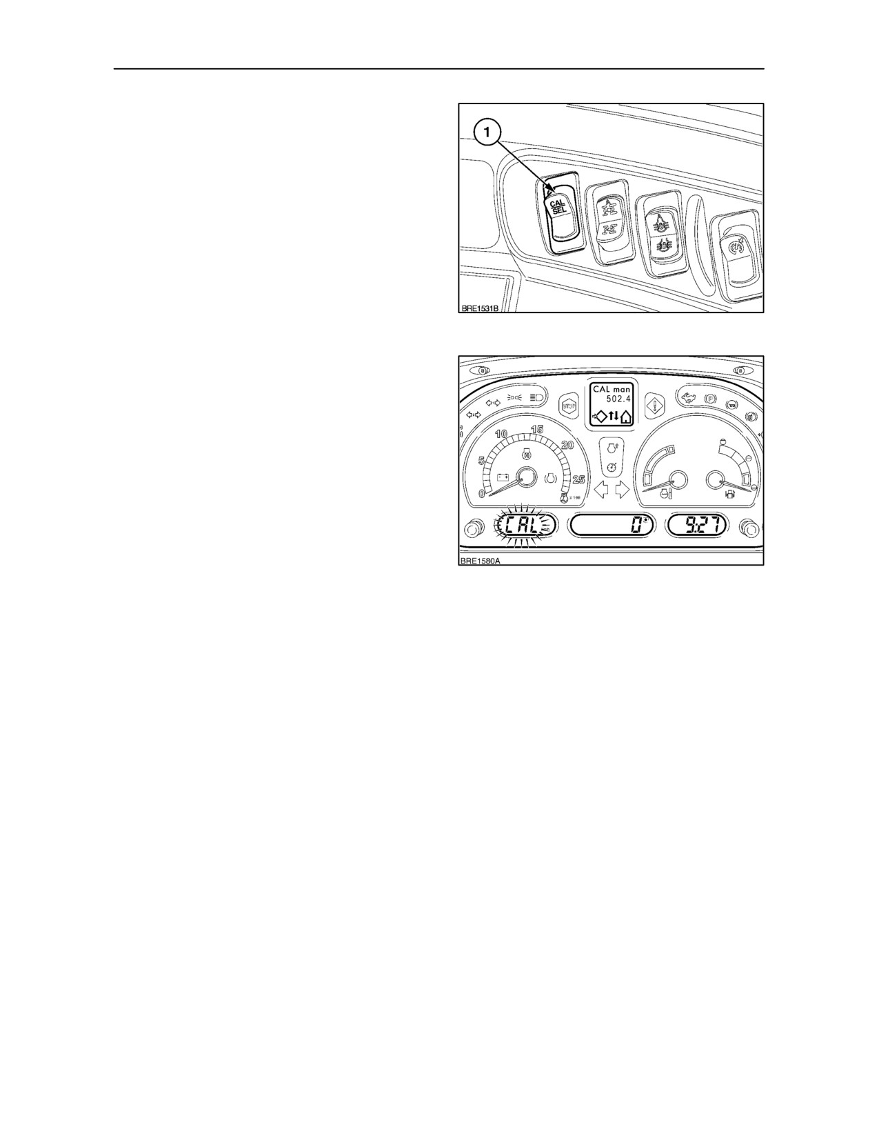
• As the centre of the front tyres passes over the
finish line, press and release the CAL/SEL button
(1) again, CAL auto OK will appear in the Dot
Matrix Display. Depress the CAL/SEL button again
select CAL display. Turn off key--start to save the
setting.
94
Manual Calibration with CAL/SEL Button
The manual calibration allows the operator to set the
rolling circumference of the rear tyre
(if known)
without the need to drive over a measured distance.
• With the tractor stationary and the key--start on,
depress and hold the CAL/SEL button for 3
seconds to display SETUP_MENU. After
2
seconds this will change to CAL. Depress the
CAL/SEL button again to select CAL
man_000.0. (The figure 000.0 may differ if a
calibration number has previously been
entered). CAL will flash in the speed display.
95
NOTE: The set up procedure may be cancelled at
any time by depressing the LCD dimmer control
button or by turning the key--start off.
IMPORTANT: When entering new tyre rolling
circumference figures, use metric values
(centimetres) with Km/h speedometer reading and
Imperial values (inches) with MPH reading, see table
on page 2--55.
• By depressing the ’h’ and ’m’ clock buttons, the
rolling circumference of the rear tyre may be
entered into the numerical display (000.0).
• Depress the ’h’ button to select the first digit to be
changed, repeated operation of the ’h’ button will
cycle the cursor through all the digits in turn. To
alter the value of the digit selected, momentarily
depress the ’m’ button until the correct figure is
shown.
• With the new rolling circumference figure
entered into the display, depress the CAL/SEL
button again to display CAL. Turn the Key--start
off to save the setting.
2--52
SECTION 2 -- CONTROLS, INSTRUMENTS AND OPERATION
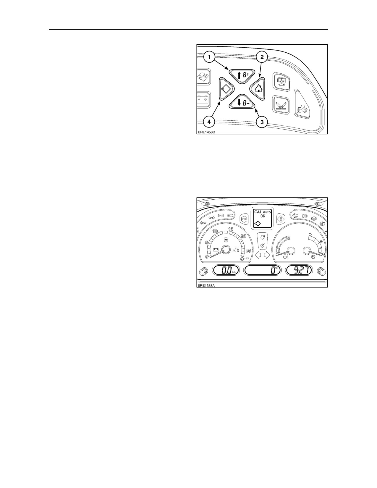
Auto Calibration with Enhanced Keypad
(where fitted)
• With the the tractor stationary and the engine
running, depress and hold the Menu/Enter key
(4) for
3
seconds. The DMD will read
SETUP_MENU, this will change to CAL after 2
seconds. Depress the Enter key again and CAL
manual will appear. Using the Menu Up key (1),
scroll through the menu until CAL auto is
displayed.
• Depress the Menu/Enter key again and CAL
auto READY will appear in the DMD. Select a
suitable transmission ratio to provide a forward
96
speed above 3 km/h (1.8 MPH). As the centre of
the front tyres passes over the start line, press
and release the Menu/Enter key. The speed
display will start to flash CAL and the central LCD
will show a four digit figure that will increase as the
tractor moves forward. The DMD will change to
display CAL auto ON.
• As the centre of the front tyres passes over the
finish line, press and release the Menu/Enter
key. CAL auto OK will appear in the Dot Matrix
Display. Depress the Menu/Enter key to store the
setting. Press and release the Exit/Cancel key (2)
Figure 96, to return to the original display.
97
2--53