New Holland T6010, T6020, T6030, T6050, T6070 Delta and Plus Tractors. Operator's Manual - page 5
SECTION 3 -- FIELD OPERATION
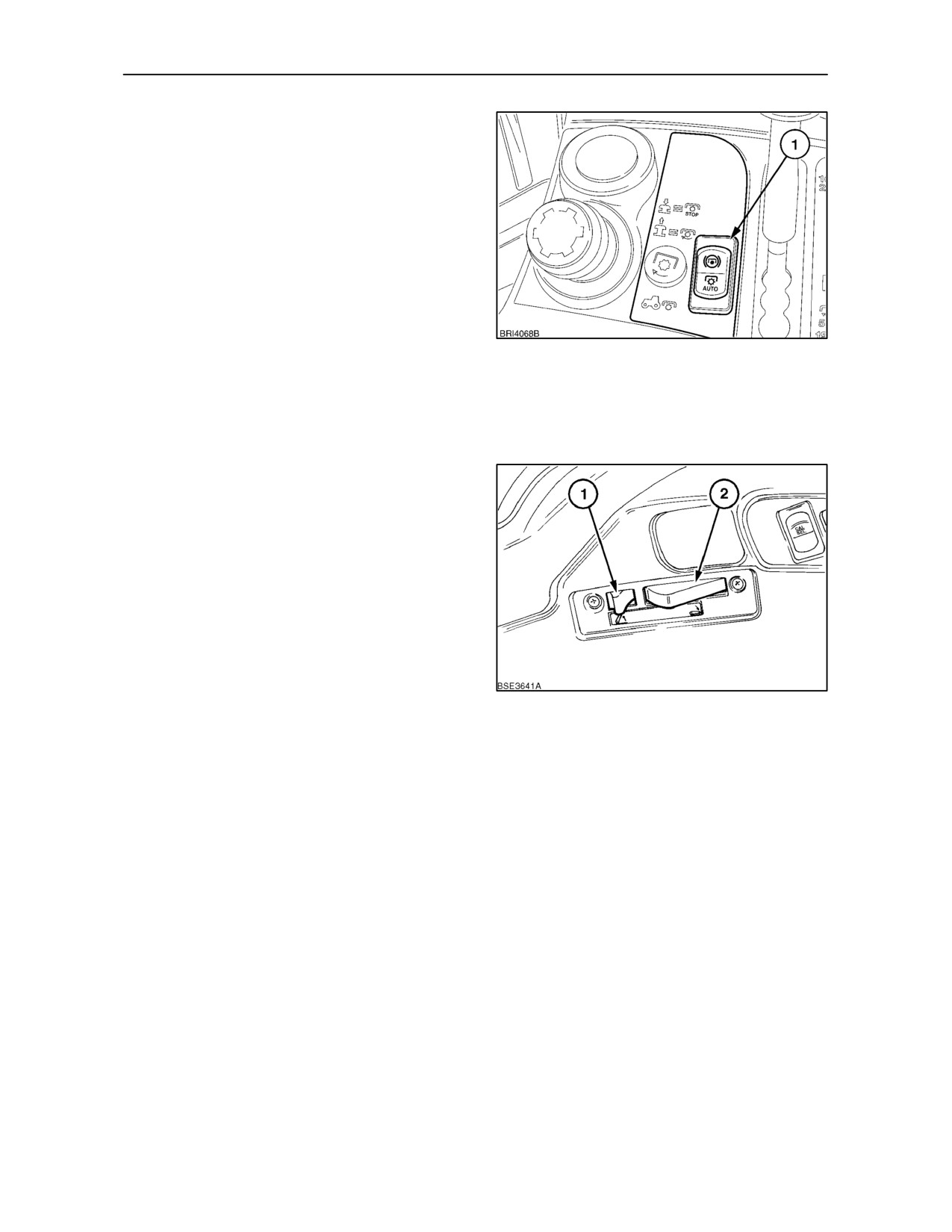
To activate the Auto function, engage the P.T.O. as
previously described and then depress and hold the
AUTO side of the switch (1), for more than one
second. The Auto P.T.O. lamp on the instrument
panel will illuminate to confirm activation.
With the 3 point hitch in the lowered position and the
P.T.O. engaged, the Auto lamp will remain on.
Raising the implement will disconnect P.T.O. drive
and cause the Auto lamp to flash. Lowering the
implement will re--engage P.T.O. drive, the Auto lamp
will cease to flash and will remain on.
Depressing the Auto P.T.O. switch again will
40
de--activate the function and the Auto lamp will
extinguish.
NOTE: The Auto P.T.O. function will be de--activated
every time the key start is switched off.
With Mechanical Draft Control
The P.T.O. will be disengaged one second after the
fast raise switch (1) is moved rearwards to the raise
position. P.T.O. drive will re--engage one second
after the hitch lowering switch (2) is fully depressed
to lower the 3--point hitch.
41
3--28
SECTION 3 -- FIELD OPERATION
Auto P.T.O. De--Activation
With either Electronic Draft Control or Mechanical
Draft Control, Auto P.T.O. will be de--activated should
one or more of the following occur:
• The tractor speed is above 0.5 Km/h (0.3 MPH)
with the 3 point hitch in the raised position for
more than 2 minutes.
• With the 3 point hitch raised, the tractor speed
falls below 0.5 Km/h (0.3 MPH), or the tractor is
stationary for more than 10 seconds with the
3--point hitch in the raised position.
• If oneof theexternalswitchesforP.T.O.or3point
hitch are operated.
• The P.T.O. is switched off using the internal or
external switches.
• Operating both internal and external P.T.O.
switches simultaneously.
• Ground drive P.T.O. is selected.
• The operator leaves the seat for more than 2
minutes with Auto P.T.O. activated and the 3
point hitch in the raised position.
To re--activate Auto P.T.O., clear the error and
re--engage the function as previously described.
NOTE: The Auto P.T.O. function will be de--activated
every time the key start as switched off.
3--29
SECTION 3 -- FIELD OPERATION
GROUND DRIVE P.T.O. (where fitted)
Three-speed ground drive P.T.O. is available on all
models in conjunction with the
3-speed
engine-driven, shiftable P.T.O. previously described.
Ground drive P.T.O. speed is directly related to
rotation of the rear wheels rather than engine speed.
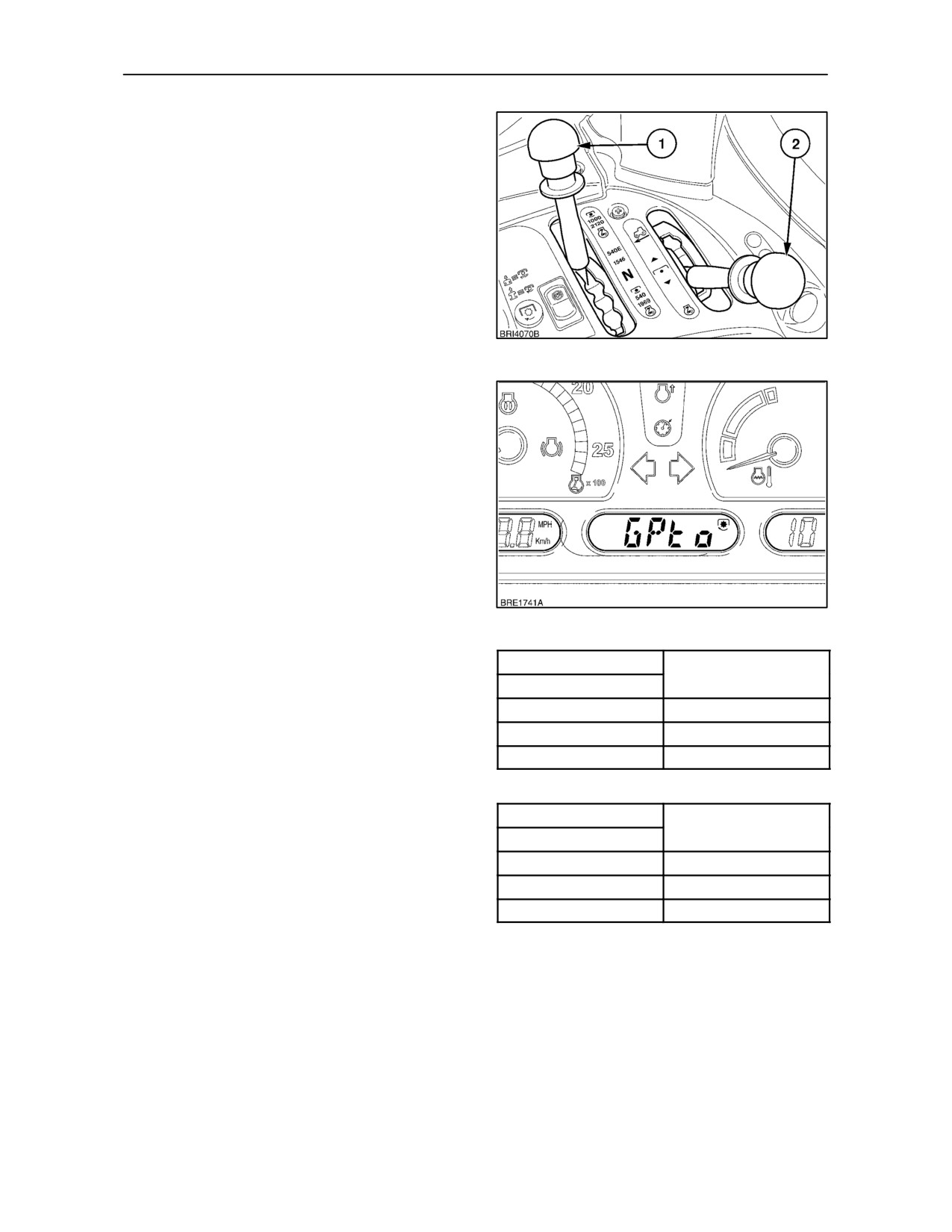
Three speed ranges are provided, selected by
means of the P.T.O. range lever (1). An additional
lever (2) is provided to select ground drive.
42
To engage ground drive P.T.O:
With the tractor stationary, ensure that the engine
P.T.O. is disengaged by pressing the selector knob
down. With reference to Figure 42, move the lever
(1), to the required P.T.O. speed range and then
select ground drive with selector lever
(2).
Engagement of ground drive will be confirmed by the
appearance of ’GPto’ in the central LCD display.
NOTE: To aid smooth engagement of ground drive
P.T.O., depress and hold both brake pedals whilst
moving the selector lever.
43
Fully depress the clutch pedal, select a transmission
Light duty axle
P.T.O. shaft revolution
gear and open the throttle to increase engine speed.
per wheel
revolution
Lever position
Allow the clutch pedal to rise. Initial movement of the
clutch pedal will cause the tractor to move and the
540 range engaged
8.83 : 1
P.T.O. shaft (and attached equipment) to rotate.
540E range engaged
11.24 : 1
1000 range engaged
15.19 : 1
The speed of rotation of the P.T.O. shaft is directly
related to rotation of the rear wheels. Shaft
revolutions for each revolution of the rear wheels are
as shown in the table on the right.
Heavy duty axle
P.T.O. shaft revolution
per wheel
revolution
Lever position
NOTE: Selecting ground drive with the engine P.T.O.
540 range engaged
9.93 : 1
function engaged will automatically disable engine
P.T.O. drive. To re--enable engine P.T.O. drive, move
540E range engaged
12.65 : 1
the selector lever to the engine drive position,
1000 range engaged
17.08 : 1
disengage and then re--engage the main P.T.O.
switch.
3--30
SECTION 3 -- FIELD OPERATION
CHANGING THE P.T.O. OUTPUT SHAFT
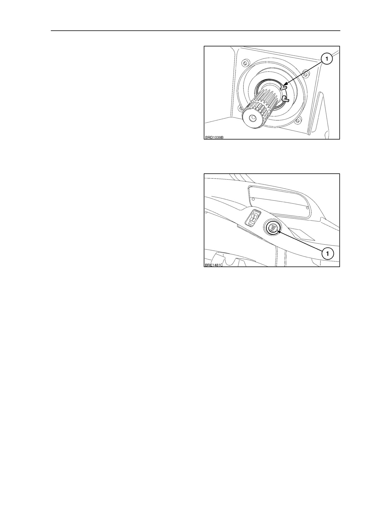
Using a suitable tool, compress and remove the
circlip
(1) from the P.T.O. housing and carefully
withdraw the P.T.O. stub shaft.
With the shaft removed, check the ’O’ ring seal in the
P.T.O. housing for any damage. Replace ’O’ ring if
worn or damaged.
Thoroughly clean the replacement stub shaft before
inserting it into the housing. Replace the circlip
ensuring it engages fully with the groove in the P.T.O.
housing.
44
Protect the removed shaft by wrapping in a clean
cloth and place in the tool box.
EXTERNAL P.T.O. CONTROLS
(where fitted)
An optional, fender-mounted P.T.O. switch (1), may
be installed on both rear fenders to aid alignment of
the P.T.O shaft splines with equipment and facilitate
stationary P.T.O. operations.
With the engine running, touch the switch
momentarily to cause the P.T.O. shaft to index round
to align the shaft splines. If the switch is pressed for
less than 5 seconds, the shaft will stop turning when
the switch is released.
45
Press and hold in the switch for more than 5 seconds
and the P.T.O. will operate continuously. Press the
switch again to stop the P.T.O. Alternatively, the
P.T.O. may be stopped by means of the in-cab
controls, as previously described.
NOTE: The warning light, on the P.T.O. control
panel, will illuminate when the P.T.O. is engaged,
momentarily or permanently.
NOTE: The P.T.O. may be engaged or disengaged
from the fender switch, whether the in-cab control is
in the on or off position.
NOTE: Simultaneous operation, within two seconds,
of in cab and external P.T.O. controls will result in an
error code showing in the central LCD. A 10 second
delay will also occur before P.T.O. control operation
will recommence.
NOTE: The soft start function will operate
irrespective of whether the P.T.O. is engaged from
inside the cab or from a fender switch.
3--31
SECTION 3 -- FIELD OPERATION
CAUTION
Before leaving the tractor to operate the external
Power Take Off switches:
• Move the gearshift levers to neutral.
• Disengage the P.T.O.
• Apply the parking brake.
With the engine running, move the hand throttle lever
to the low idle position (fully rearwards).
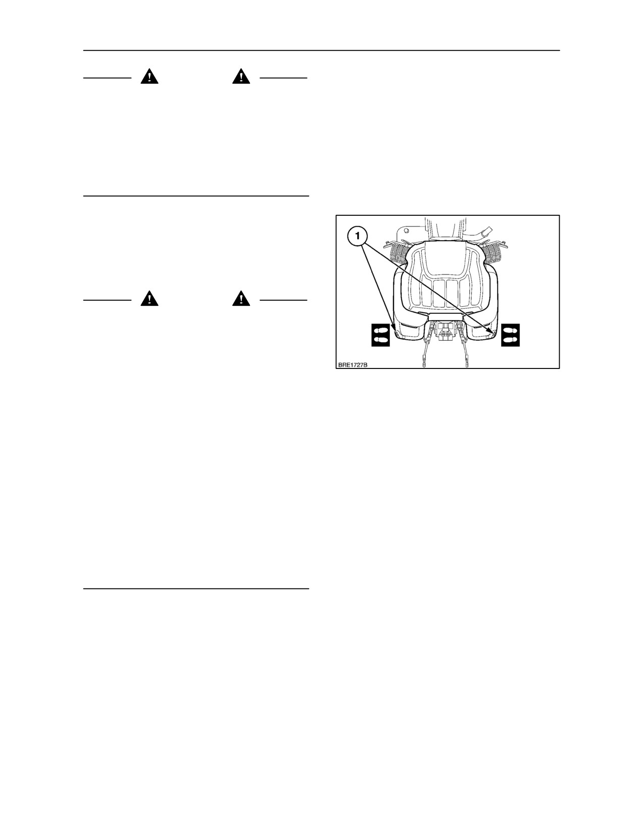
The operator must only activate the external Power
Take Off switches (1) while standing to the side of the
tractor (outboard of the rear tyres). To avoid damage
to implement or tractor, operation of the in cab and
external P.T.O. switches should not be carried out
simultaneously.
WARNING
Before using the external Power Take Off switches,
ensure that no person or object is in the area of the
implement, 3-point linkage or P.T.O.shaft.
Never operate the external switches while standing:
• Directly behind the tractor or tyres.
46
• Between the lower links.
• On or near the implement.
• Never extend arms, legs, any part of the body or
any object into the area near the 3-point linkage,
P.T.O. shaft or implement while operating the
external switch.
• Never have an assistant working the opposite set
of controls.
• When moving to the opposite set of controls,
move around the tractor or implement.
• Do not cross between the implement and tractor.
3--32
SECTION 3 -- FIELD OPERATION
FRONT P.T.O. AND THREE--POINT HITCH
(where fitted)
Tractors with four wheel drive may be equipped with
an engine-driven P.T.O. and front hydraulic lift.
These features are available as a factory installed
option or dealer installed accessory.
FRONT P.T.O.
The front power take--off (P.T.O.) transfers engine
power directly to front-mounted equipment via a 6
spline shaft. The P.T.O. shaft rotates anti-clockwise
(as viewed from the front).
NOTE: A 21 spline shaft is available as a dealer
installed accessory.
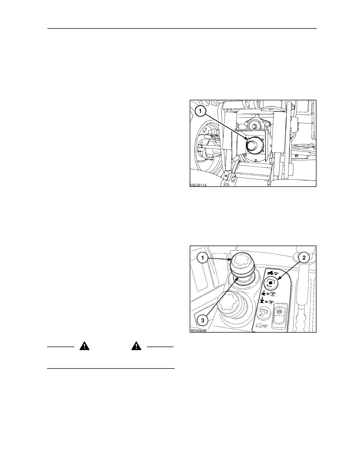
A plastic cap (1) is provided over the P.T.O. shaft. Pull
the cap to remove.
NOTE: With the engine stopped, the P.T.O. brake is
47
released and the shaft may be turned by hand to aid
implement shaft alignment.
The front P.T.O. is electro--hydraulically operated
and is activated by a selector knob on the right-hand
console, similar to the rear P.T.O.
With the engine running at 1000 rev/min. or less,
press the knob (1) and lift the collar (3) and knob up
to engage the P.T.O. The knob will remain up while
the P.T.O. is engaged and the adjacent warning light
(2) will be illuminated. Open the throttle to increase
engine speed to 2120 rev/min and provide a P.T.O.
shaft speed of 1000 rev/min. To disengage the
P.T.O., press the P.T.O. selector knob (1), down.
NOTE: If the engine is stopped, the P.T.O. will not
operate when the engine is restarted until the P.T.O.
knob is reset. Return the selector knob manually to
the ‘off’ position (by pressing the knob down) then
re-engage the P.T.O., as previously described.
48
DANGER
To avoid inadvertent movement of the implement,
disengage the P.T.O. after each use.
3--33
SECTION 3 -- FIELD OPERATION
FRONT THREE--POINT HITCH
(where fitted)
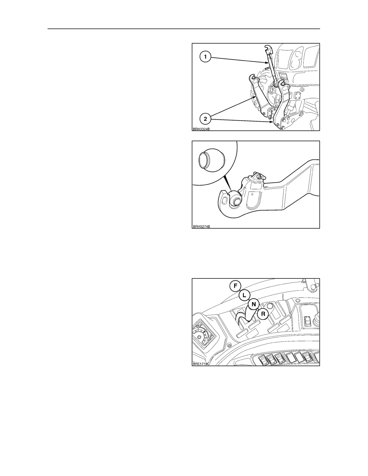
The optional front hitch consists of an adjustable top
link (1) and a pair of folding lower links (2). The top
link and the lower links have open claw ends that
permit rapid coupling and uncoupling of implements.
The claws are equipped with self-locking latches to
ensure positive retention of the tractor linkage to the
implement.
49
Three ball-bushings are supplied for installation on the
implement, if required.
50
Operating the Front Linkage
The front hitch may be controlled through the rear
remote valves, or by a dedicated mid-mounted twin
spool remote valve.
-- with mechanical rear remote valves:
Using valves I or II at the rear of the tractor, operation
of the front hitch may be controlled via the remote
valve levers.
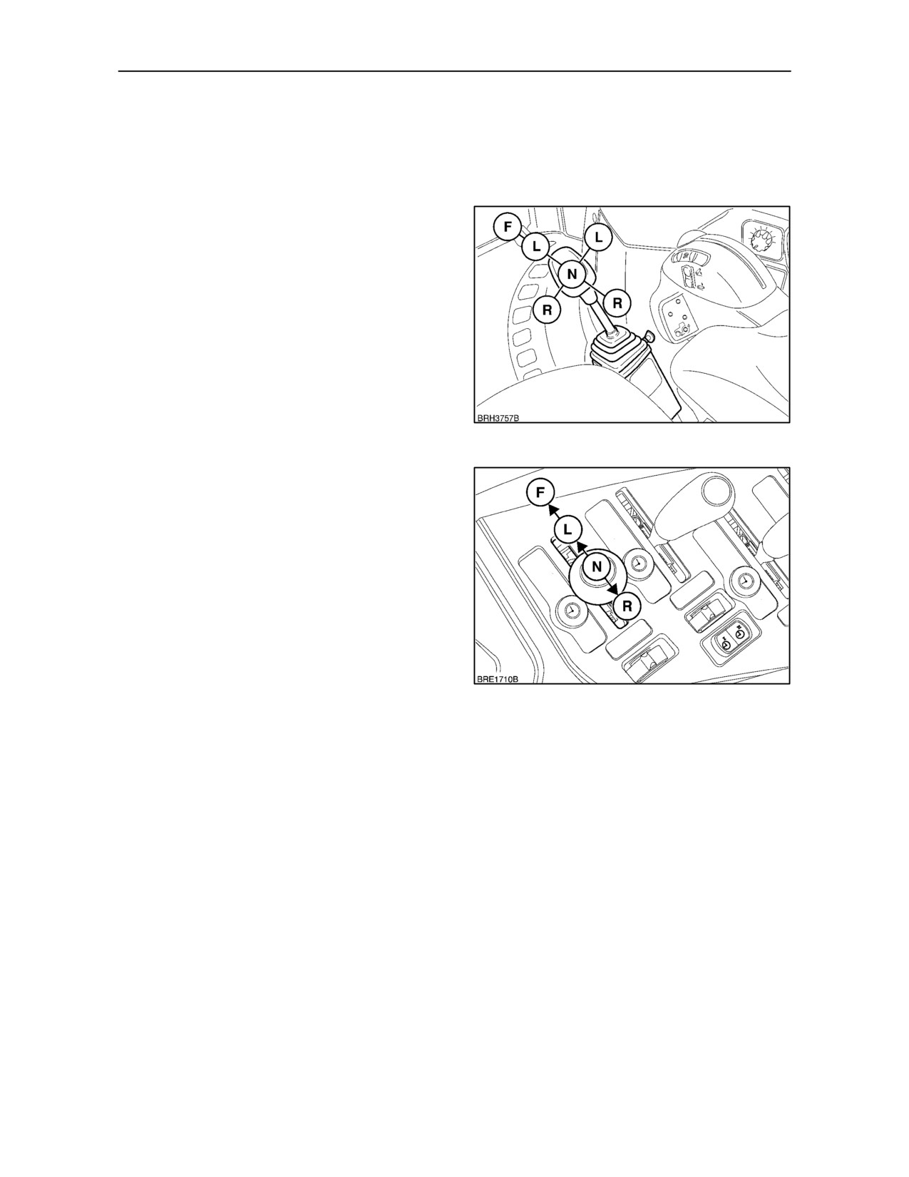
With the front linkage connected to valve number I,
pull the lever rearwards (R) to raise the front linkage.
Move the lever to (N) to halt linkage movement, the
linkage will maintain its height position. Select (L) to
lower the linkage. With the lever in the float position
(F), the linkage can move up and down (float)
allowing the implement to follow the ground
contours.
51
3--34
SECTION 3 -- FIELD OPERATION
If the implement requires additional hydraulic
services, these may be connected to any unused
remote valve. However, for convenience, it is
recommended the second valve (II) is used for this
purpose.
As an alternative, the levers operating remote valves
I and II may be replaced by a joystick located in a
forward position on the right--hand side of the
operators seat.
IMPORTANT: With the joystick operating the rear
remote valves, a float position (F) is available by
moving the lever fully to the right. This function is not
available when operating with a mid--mounted
2--spool remote valve.
52
-- with Electro Hydraulic remote valves:
Electro Hydraulic valves may be used to operate the
front hitch using the remote valve lever or electronic
joystick (where fitted). The Electro Hydraulic levers
function in a similar way to the mechanical levers.
The standard default valve to operate the hitch will
always be valve number IIII. However, it is possible
to set the default to alternative remote valve if
required.
The default valve (IIII) is programmed to operate in
conjunction with the front hitch height limiter. If an
53
alternative valve is used, the height limiter will not
function until the new valve has been programmed.
To reset the default valve, the tractor must be
stationary with the parking brake applied, ensure all
hydraulic lines are disconnected from the remote
valve couplings.
3--35
SECTION 3 -- FIELD OPERATION
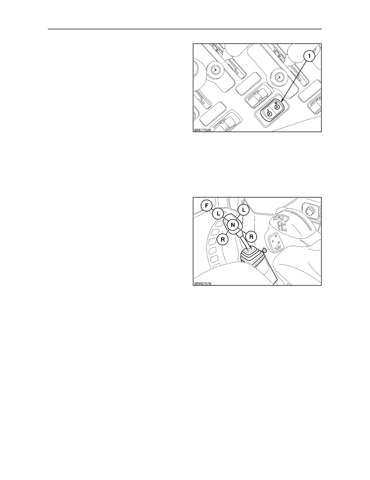
• Ensure all EHR timer switches (1), are in the off
position.
• Turn the key--start on, but do not start the engine.
• Depress the timer switch for remote valve No.1
then, within five seconds, depress the timer
switch for valve No. 2.
•
’FEhr’ will appear in the Dot Matrix Display, after
two seconds this will change to show the current
default valve, for example ’Ehr4’.
• Choose the new default valve and depress the
timer switch for that valve three times, the display
will change to show the new selection, for
54
example ’Ehr1’.
• Turn the key--start off, the new default valve for
front linkage operation is now memorised.
NOTE: For programming procedures on EHR
remote valves, see page 3--66.
With twin spool mid mounted remote valve:
(where fitted)
The optional mid mount remote valve is controlled by
a joystick located on the right--hand side of the seat.
The mid mount valve provides two additional double
acting services, one of which may be utilised to
operate the front hitch.
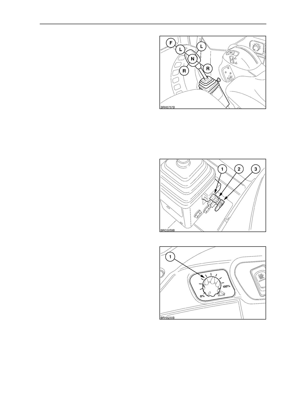
Pull the joystick rearwards
(R) to raise the
implement. When the hydraulic lift reaches the
height set by the height limit rotary control the
joystick will return automatically to neutral
(N).
Alternatively, the hydraulic lift will stop raising when
55
the joystick is manually returned to the neutral
position. Moving the joystick fully rearward against
spring pressure will provide a faster rate of lift.
Pushing the joystick forward to the ‘lower’ position (L)
will cause the implement to lower to the ground at a
controlled rate of descent.
Further forward movement of the joystick will select
‘float’ (F) which will allow the cylinder to extend or
retract freely. When in the float position, pushing the
joystick fully forward against spring pressure will
slow the movement of the cylinder.
NOTE: Always use the ’float’ position to lower a
single--acting cylinder. The ’lower’ position is for
double--acting cylinders only.
3--36
SECTION 3 -- FIELD OPERATION
The joystick may also be moved laterally, (R) and (L),
to provide oil flow for equipment connected to the
optional front couplers.
NOTE: With the joystick operating the rear remote
valves, a float (F) position is available by moving the
lever fully to the right. This float facility is not
available when operating with a mid--mounted
2--spool remote valve.
The joystick has the added advantage of being able
to operate two cylinders simultaneously by moving it
diagonally.
56
IMPORTANT: When operating with a hydraulic
motor always use ‘lower’ and ’float’ positions to
control motor rotation. To stop the motor, move the
lever from the ‘lower’ (drive) position to the ‘float’
position. The motor will then slow to a gradual halt
and not stop abruptly which may cause internal
damage to the motor.
The joystick safety lock lever is used to prevent
accidental operation of the remote valve(s).
The safety lock on the joystick has three positions:
1. Fully out.
All joystick movements available.
2. Mid Position. Lateral movement locked out.
3. Fully in.
All joystick movements locked.
57
Setting the Height of the Front Hitch
Height limit control is provided by a rotary knob (1) on
the right-hand console. Fully clockwise is maximum
height. Turn anti-clockwise for minimum height.
NOTE: The height limit setting is affected by the oil
flow through the system. For example, if the flow
control setting is set to maximum and engine speed
is high then hitch height may be up to 100 mm (4 in.)
higher than would be achieved if engine speed and
oil flow rate were low.
58
3--37
SECTION 3 -- FIELD OPERATION
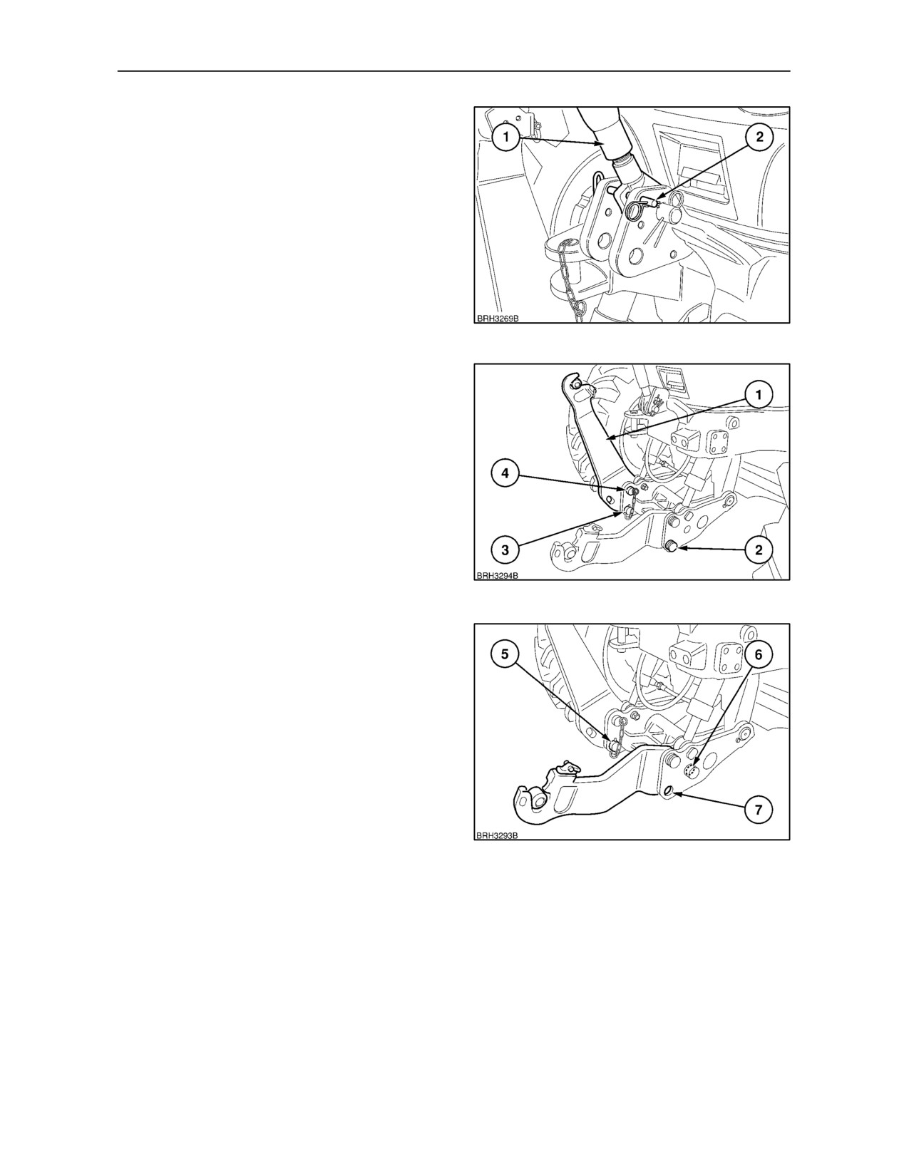
Transport Position
The top link and lower links should be placed in the
transport position when not in use. Raise the top link
(1) to the vertical position and secure by inserting the
lock pin (2) through the top link and anchor bracket.
Secure the pin with the spring clip as shown.
59
Each lower link pivots about the pivot bolt (2). The
pivot bolt should not be removed unless it is required
to remove the lower links. Extract the lower pin (3)
from the link assembly and raise the lower link (1) to
the vertical position, as shown. Insert the pin through
the upper hole in the inner link arm when the holes
in the inner and outer links (4) are correctly aligned.
Before operating the tractor ensure both pins are
secured with lynch--pins.
60
To convert to the working position, remove the
lynch--pin, pull out the pin (5) and manually lower the
link arm down to the operating position, as shown.
Install the removed pin in one of the holes (6) or (7),
as required.
When installed in the rear hole (6) as shown, the
lower link will be locked as a rigid unit. If the pin is
installed in the front hole (7), the lower link will be
allowed to move up and down freely (float) through
a range of approx. 75 mm (3 in). Secure the pin with
the lynch--pin.
Repeat on the other lower link, ensuring that both
61
lower links are set up the same, i.e., both are locked
as rigid units or both are allowed to float.
3--38
SECTION 3 -- FIELD OPERATION
NOTE: With the lower links pinned in the float
position, the left and right-hand sides of the
implement can move up and down independently to
allow for operation on uneven surfaces. In addition,
the remote control valve float function will allow the
whole implement to move up or down as it passes
over uneven ground.
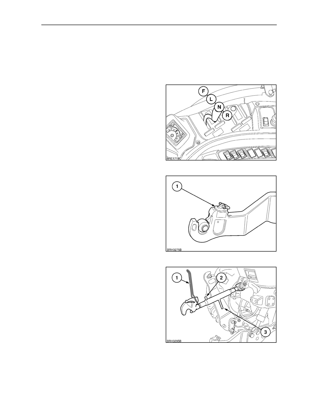
Coupling Implement to Tractor
Start the engine. Move the remote valve lever or
joystick (where fitted) from neutral (N) to lower (L)
until the link arms are just clear of the ground.
Position the tractor so that the open claw ends are
beneath the implement hitch pins.
62
Slowly move the remote valve lever or joystick
rearward to raise the lower links until the claw
couplers engage the ball-bushings. An audible click
will be heard as the self-locking latches engage the
ball-bushings on the implement. The lift control
should be returned to the neutral position before the
lower links start to lift the implement from the ground.
IMPORTANT: Before operating the tractor, ensure
the release latches (1), are fully retracted into the link
end.
63
Attach the top link to the implement, adjusting to the
correct length by rotating the threaded centre section
using the handle (3) as leverage. To prevent the
centre section from rotating while in work, place the
locking latch (1) over the pin (2) or adjuster handle
(3). The top link has a similar claw end to the lower
links. Lower the top link claw onto the upper
implement ball-bush and press down until the latch
is heard to engage.
The implement supports, where fitted, may now be
removed or retracted and the implement supported
on the front linkage.
64
3--39
SECTION 3 -- FIELD OPERATION
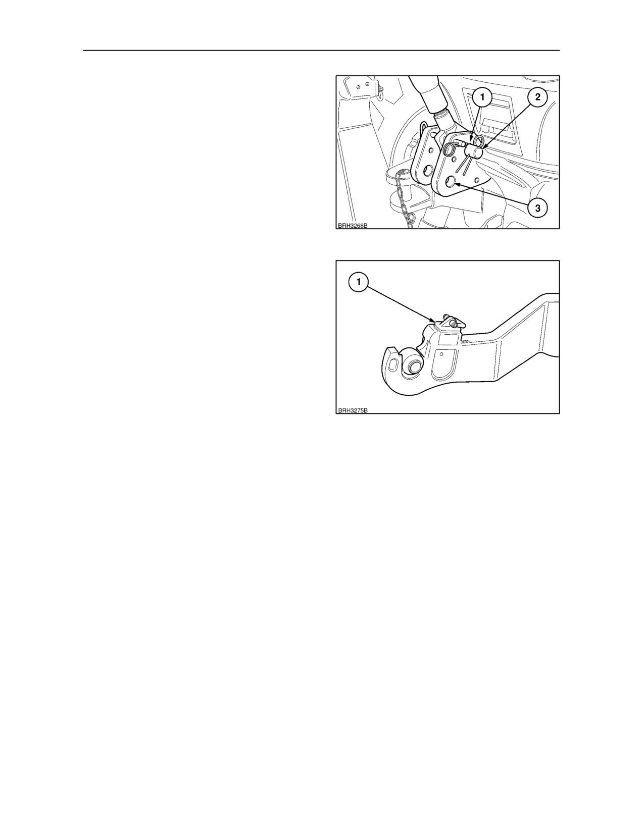
The top link is connected to the bracket with the pin
(2) secured by the spring pin. Two holes are provided
in the top link bracket for location of the top link. Use
the top hole (1), as shown, for maximum lift capacity.
Use the lower hole (3), to provide the greatest
implement height, when raised.
65
Uncoupling Implement from Tractor
Using the remote lever or joystick, lower the
implement to the ground, ensuring that it cannot fall
when disconnected from the front hitch. Use the
implement supports (where fitted).
Pull back the lever on the top link to release the claw
from the implement upper hitch pin.
Pull the ring (1) on both lower links fully rearwards.
The lever will lock in position with the latch retracted.
This will allow the links to clear the ball-bushings on
the implement lower hitch pins when the links are
66
lowered fully.
Fully lower the lower links using the remote lever or
joystick and reverse the tractor clear of the
implement.
3--40
SECTION 3 -- FIELD OPERATION
MECHANICAL LOWER LINK SENSING
HYDRAULICS (where fitted)
Your tractor is equipped with an hydraulic system
providing accurate and sensitive control over a wide
range of operating conditions. Two systems are
employed, dependent upon the specification level of
your tractor.
The basic hydraulic system, as discussed in this
section of the Manual, is a mechanically controlled
system that offers Position Control and Draft Control
sensed through the lower links of the 3-point linkage.
67
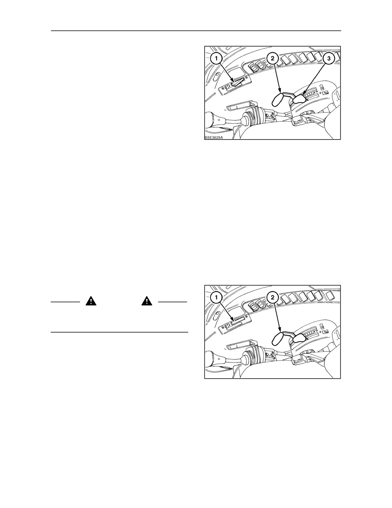
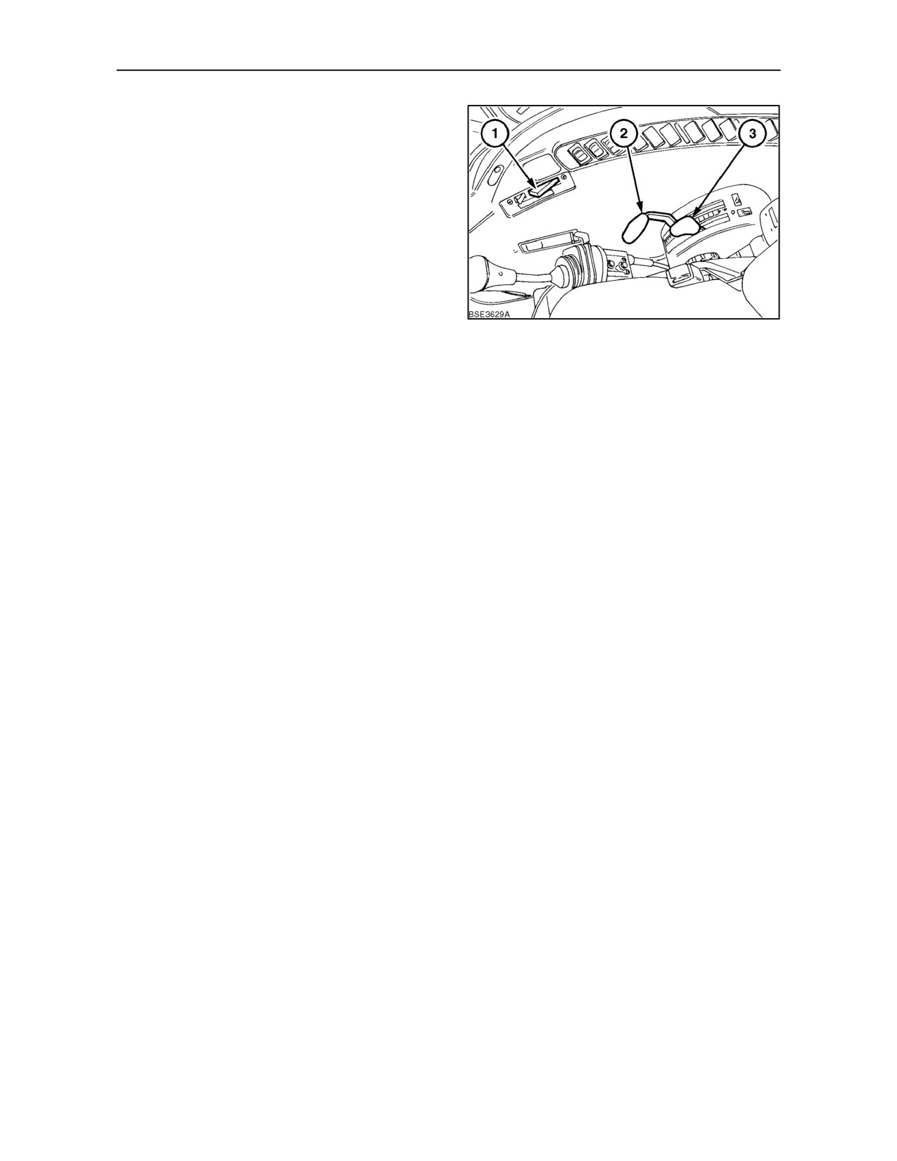
The system is controlled by the Draft Control lever (3)
the Position Control lever (2) and the fast raise button
(1). The fast raise button will fully raise the 3--point
linkage (and attached implement) independently of
the Position or Draft Control levers.
Position Control provides accurate and sensitive
control of implements, such as sprayers, rakes,
graders, etc., that operate above the ground. Once
set, the position of the lower links will remain at a
constant height unless adjusted using the lift control
lever.
Draft Control is most suitable for mounted
implements operating in the ground. Changes in the
working depth or changes in soil resistance cause
the draft loading on the implement to increase or
decrease.
Pre--operation Checks
CAUTION
Before starting the engine, always ensure that the
fast raise button (1) is pushed in, as shown, to
prevent inadvertent raising of the 3--point linkage.
IMPORTANT: Some mounted or semi--mounted
equipment may interfere with, and damage the cab.
To avoid the possibility of cab damage, check for
adequate clearance by slowly raising the equipment
using the Position Control lever (2). If any part of
the equipment comes closer than 100 mm (4 in.) to
68
the cab, stop raising. Stop the engine, lower
equipment to the ground and adjust the height limiter
cam.
3--41
SECTION 3 -- FIELD OPERATION
Height Limiter Cam
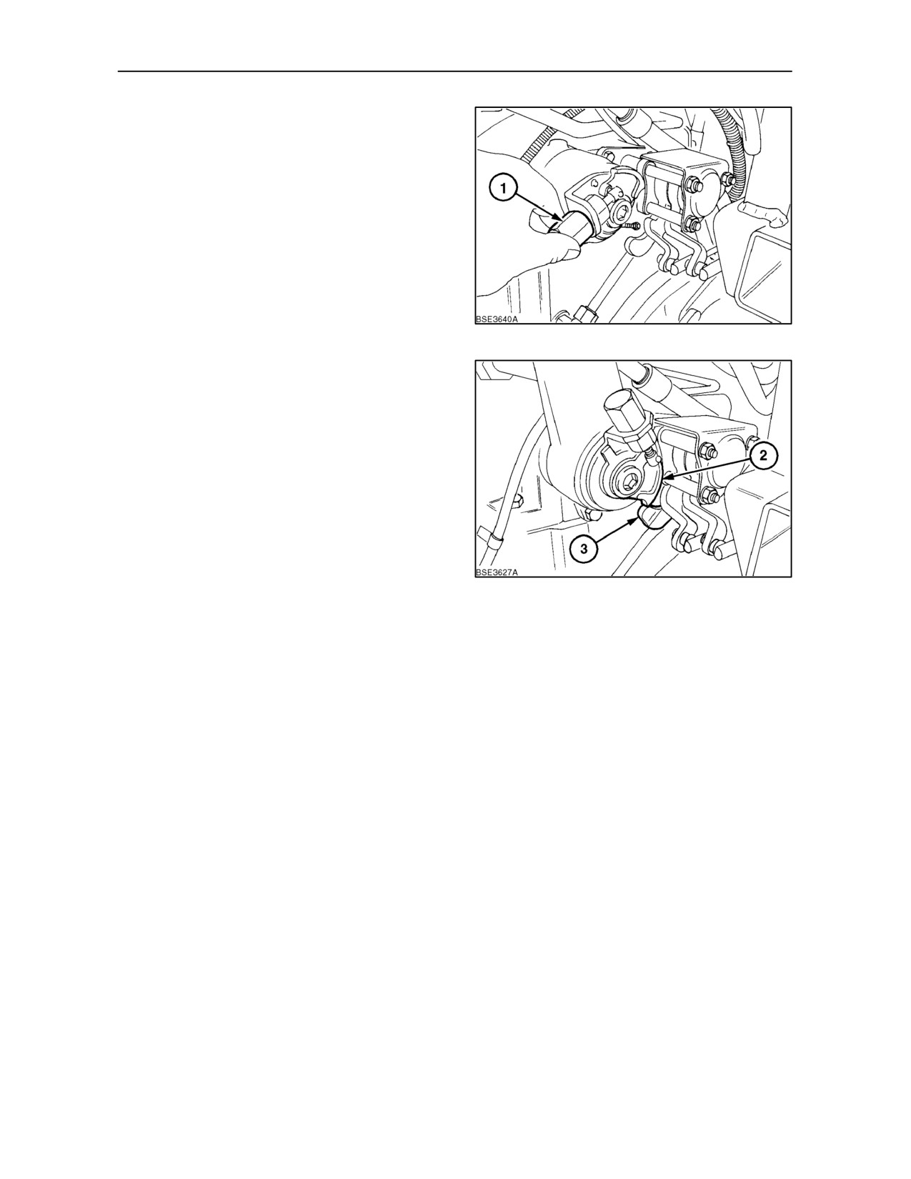
The height limiter cam is on the right-hand end of the
hydraulic rocker shaft. Turn the cam adjuster (1)
clockwise to decrease implement height, turn
anti--clockwise to increase implement height. The
cam adjuster is self locking and will remain in position
once set.
69
The cam (2) is shown in contact with the lever (3) at
the maximum height position. To achieve full lift
height, turn the cam adjuster fully anti--clockwise
until the cam is clear of the lever when the lower links
are in the fully raised position.
NOTE: The height limiter cam only affects operation
of the fast raise button. When the cam comes into
contact with the lever, it cancels the signal from the
fast raise button and stops the 3-point linkage from
raising further.
Repeat the previous step to check for implement to
cab clearance. If clearance is inadequate, move the
70
cam further in a clockwise direction. When clearance
is satisfactory, proceed to operate.
3--42
SECTION 3 -- FIELD OPERATION
POSITION CONTROL OPERATION
IMPORTANT:Always set the system to Position
Control at any time when not actually operating in
Draft Control, such as when attaching or transporting
equipment or when no equipment is attached.
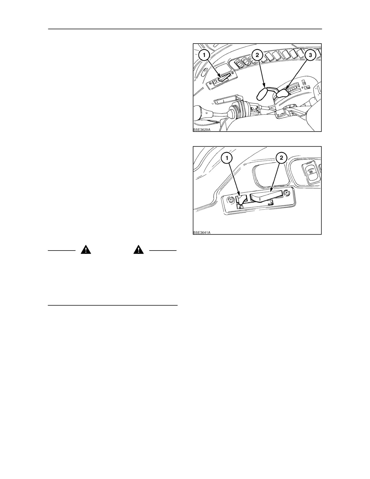
Move the Draft Control lever (3), fully forward in the
quadrant. Set the required implement height/depth
using the Position Control lever (2). Pull the lever
back to raise the implement, push forward to lower.
Implement height/depth is relative to the position of
the lever in the quadrant.
71
To raise the implement at the end of each pass, or
whenever required, move the latch (1) rearward to
release the fast raise button. The button (2) will pop
out, as shown and the
3--point linkage
(and
implement) will raise to full lift height (as determined
by the height limiter cam setting) without the need to
move the Position Control lever.
To lower the implement, simply press the fast raise
button (2) fully in, as shown, and the implement will
lower to the height/depth set by the Position Control
lever.
72
CAUTION
When transporting equipment on the
3--point
linkage, raise the implement using the Position
Control lever. The hydraulic system will maintain the
equipment at the height set by the Position Control
lever and prevent the equipment lowering and
becoming damaged, damaging the road surface or
causing personal injury.
3--43
SECTION 3 -- FIELD OPERATION
DRAFT CONTROL OPERATION
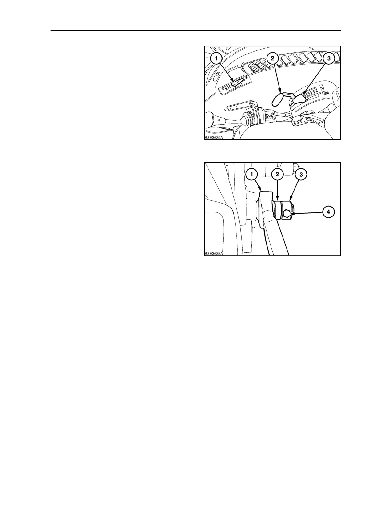
When starting work, move the Position Control lever
(2) fully forward and lower the implement into work
using the Draft Control lever (3). Push the lever
forward to increase the draft loading. Pull rearwards
to reduce the draft loading. In most circumstances
forward movement of the lift control lever will
increase implement depth and rearward movement
will reduce the depth.
Once set, the tractor hydraulic system will
automatically adjust the implement depth to maintain
an even pull on the tractor and so reduce wheel slip
73
to a minimum.
Observe the implement as it pulls through the soil. If
the hydraulic system reaction (vertical movement of
the implement) is too great or too frequent then
system sensitivity may be reduced by adjustment of
the sensor bar spacers.
To move a spacer, remove the nut and bolt (1), end
stop (2), lower link (3) and spacer (4). Re-install the
spacer first, followed by the lower link and end stop.
Secure the end stop with the nut and bolt. Tighten the
nut securely.This is the most sensitive position,
recommended for light implements or light draft
loads.
74
To reduce system sensitivity, move the spacers at
each end of the sensor bar to the outside of the lower
links as shown in Figure 74. This is the least sensitive
position, recommended for heavier implements or
heavy draft conditions.
As with Position Control operation, use the fast raise
button to raise and lower the 3--point linkage (and
implement) at the end of each pass. Do not move the
Draft Control lever as this will affect the previously
determined setting.
3--44
SECTION 3 -- FIELD OPERATION
Combined Position and Draft Control
Operation
When starting work, lower the implement to the
required depth by means of the Draft Control lever
(3), as previously described. Observe the implement
as it pulls through the soil.
When the implement stabilises at the required depth,
ease the Position Control lever (2) back until the lift
arms tend to rise. The lift linkage is now operating in
Draft Control but the implement is prevented, by the
Position Control function, from sinking too far when
the draft load reduces.
75
Float Operation
To operate with the lift in float mode move the Draft
and Position Control levers fully forward. This will
enable the lift arms to move up and down freely
allowing the implement to follow the ground
contours.
3--45
SECTION 3 -- FIELD OPERATION
EXTERNAL HYDRAULIC POWER LIFT
CONTROL
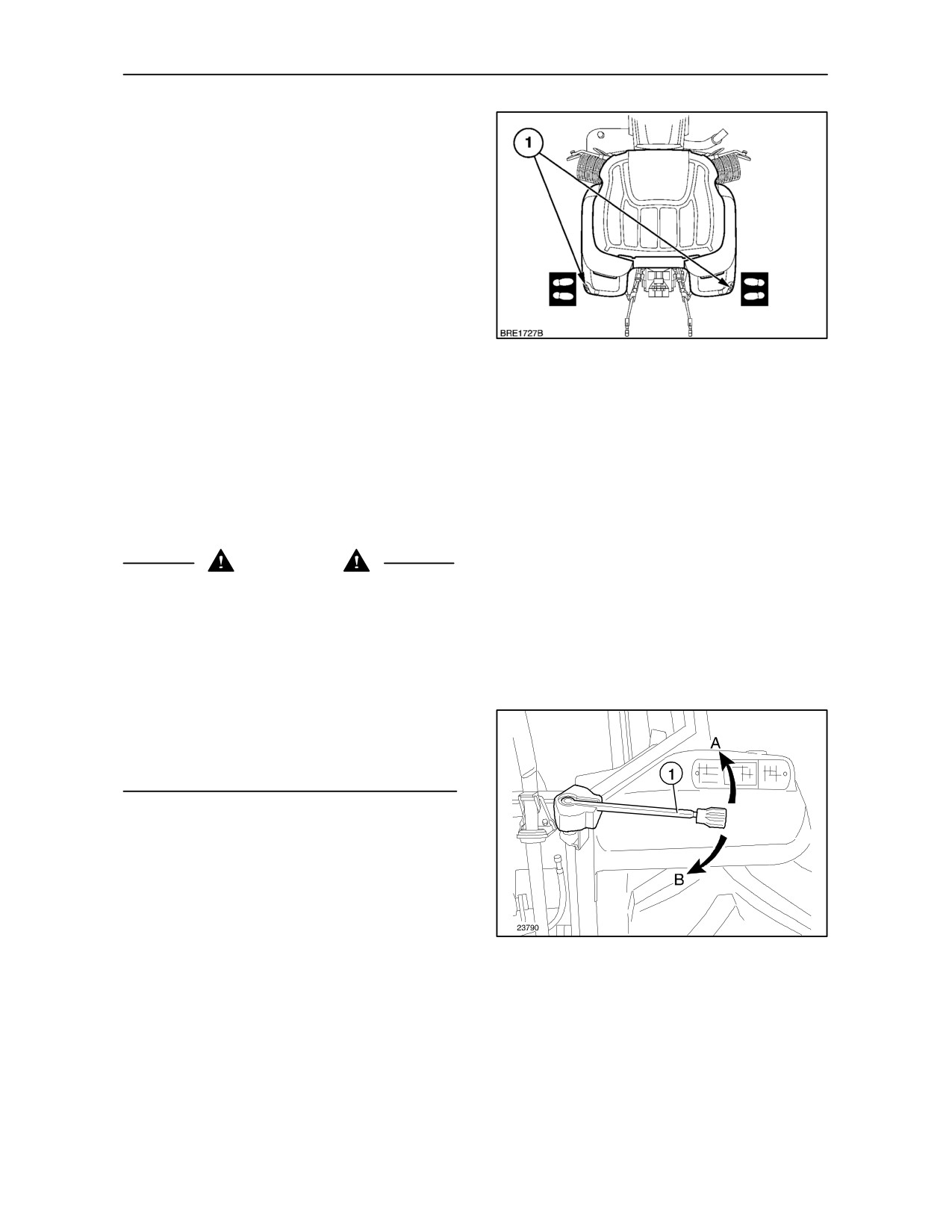
To aid the connection of implements, an external
power lift control lever is provided inboard of the rear
right-hand fender.
Before leaving the tractor to operate the external
power lift control:
• Apply the parking brake
• Move the gearshift levers to neutral
76
• Disengage the P.T.O.
• Move the Draft Control lever fully forward
• Move the hand throttle lever to the low idle
position (fully rearwards)
IMPORTANT: The operator must only activate the
external power lift control lever while standing to the
right of the tractor, outboard of the rear tyre (the
shaded area in Figure 76 ).
WARNING
Before using the external hydraulic power lift control,
ensure that no person or object is in the area of the
implement or 3--point linkage. Never extend arms,
legs, any part of the body or any object into the area
of the 3--point linkage or implement.
Never operate the external power lift control while
standing:
• Directly behind the tractor or tyres
• Between the lower links
• On or near the implement
To operate the external lift control, extract the lever
from its housing and locate in the top of the lift control
mechanism as shown.
Move the lever upwards (anti--clockwise) to raise the
3--point linkage.
Move the lever downwards (clockwise) to lower the
77
3--point linkage.
3--46
SECTION 3 -- FIELD OPERATION
ELECTRONIC DRAFT CONTROL
(where fitted)
NOTE: Depending on tractor specifiication, some of
the Electronic Draft Control features shown in this
section may not be fitted.
This system described here is known as Electronic
Draft Control. This electronically controlled hydraulic
system senses changes in the draft loading via
sensors in the lower link pins of the 3--point linkage
and changes in the position of the linkage via a
sensor on the cross shaft. The system functions in
Position Control or Draft Control.
Position Control provides accurate control of
implements, such as sprayers, rakes, graders, etc.,
that operate above the ground. Once implement
height has been set, the system will maintain the
selected position irrespective of any external forces
acting upon it.
Draft Control is designed for mounted or
semi-mounted implements operating in the ground.
Changes in soil resistance cause the draft loading on
the implement to increase or decrease.
Draft Control Operational Notes
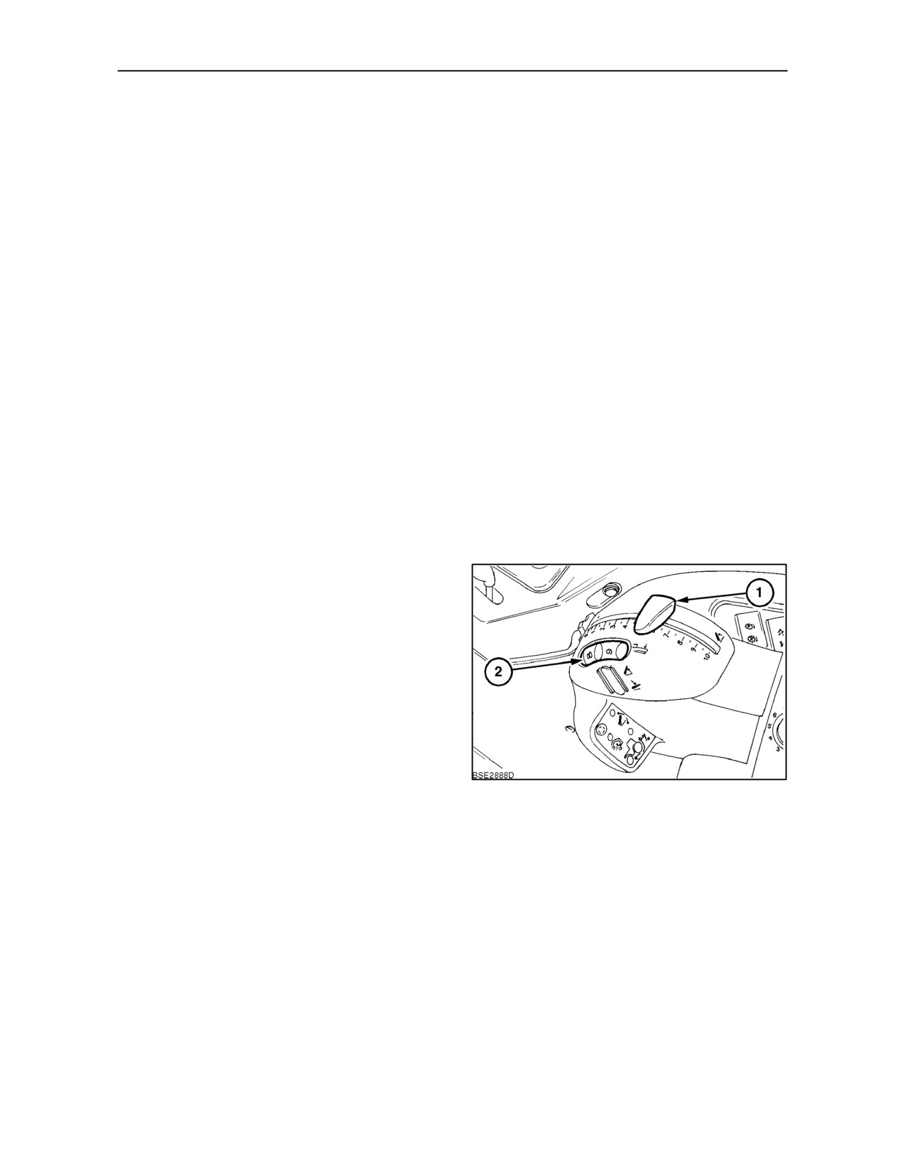
Draft control sets the working depth in the soil by
maintaining a constant draft load. If the Position
Control lever (1), is set just below the normal Draft
Control working depth, it will prevent the implement
from ‘diving’ or working too deep if an area of soft or
light soil is encountered.
Position Control will override draft control when the
Position Control lever is moved above the working
depth set by the draft loading wheel (2). Therefore,
the Position Control lever can be used to lift the
implement out of the ground, from the normal Draft
78
Control working depth, without changing the Draft
Control setting.
This function can be useful when a gradual lift out is
required. The thumbwheel stop can be set so that the
Position Control lever can be returned quickly to a
lower limit position just below the normal Draft
Control working depth.
The raise/lower switch would normally be used to
raise or lower an implement during a work cycle.
3--47
SECTION 3 -- FIELD OPERATION
Control Pod
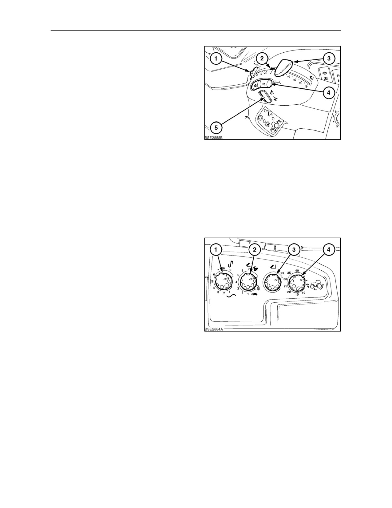
The thumbwheel (1), when rotated, will move the
adjustable stop (2).
The position control lever
(3), is used to set
implement height, when operating in Position
Control. Use it to set the maximum implement depth
when operating in Draft Control.
The draft loading wheel (4), determines the draft load
and therefore implement working depth by setting a
force on the draft sensitivity pins. Selecting position
10
will provide maximum load and therefore
79
maximum implement depth.
The raise/lower switch (5) Figure 79, is a three
position, spring centered switch that enables the
operator to rapidly raise the implement to the position
set by the height limit control and to lower the
implement back down to the working depth/height
set by the Position or Draft Controls, without
disturbing the settings. The switch also provides for
faster ground engagement, if required. For detailed
information, see text on page 3--54.
EDC Panel
The draft sensitivity control (1), is used to make the
system more sensitive or less sensitive to changes
in draft loading. Maximum sensitivity is obtained by
rotating the control fully clockwise.
The drop rate control (2), adjusts the speed at which
the three--point linkage drops during the lowering
cycle. Position 1 selects the slowest drop and is
denoted by the tortoise symbol, position 7 provides
the fastest rate of drop.
The height limit control knob (3), limits the height to
80
which the linkage may be raised. Adjust this knob to
avoid the possibility of a large implement damaging
the tractor when fully raised.
The slip limit control knob (4), available only with the
optional radar sensor unit, enables the operator to
select a wheel slip threshold, above which the
implement will raise until wheel slip returns to the set
level.
3--48
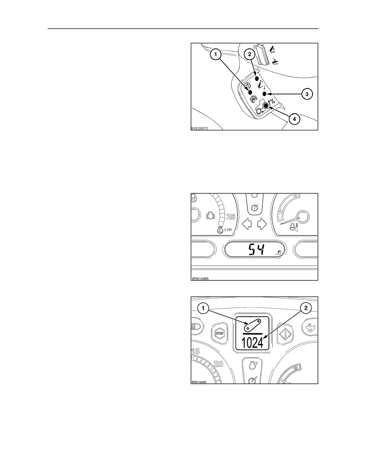
SECTION 3 -- FIELD OPERATION
Indicator Lights
The malfunction warning light
(1), serves two
purposes:
-- Flashing light means that there is a malfunction
in the system circuits. This will be accompanied by
the hitch error symbol appearing in the Dot Matrix
Display.
-- Steady light signifies ‘hitch disabled’. Again, the
‘hitch disabled’ warning is repeated in the Dot Matrix
Display with the hitch symbol.
The indicator lights (2) and (3), operate when the
position control lever is used to raise or lower the
81
implement or as lift and lower corrections occur
during normal tractor operation. The lower light (3)
will illuminate when the 3--point linkage lowers. The
upper light (2) will illuminate when the linkage raises.
A slip limit ‘on’ indicator (4), illuminates when the
wheel slip limit control is activated.
Hitch Position Display
The digital display in the instrument panel indicates
the position of the lower links over a scale of ‘0’ to
‘100’. A display of ‘0’ indicates that the links are fully
lowered. ‘100’ indicates they are fully raised. Select
the display using the CAL/SEL switch or the
Enhanced keypad (where fitted).
82
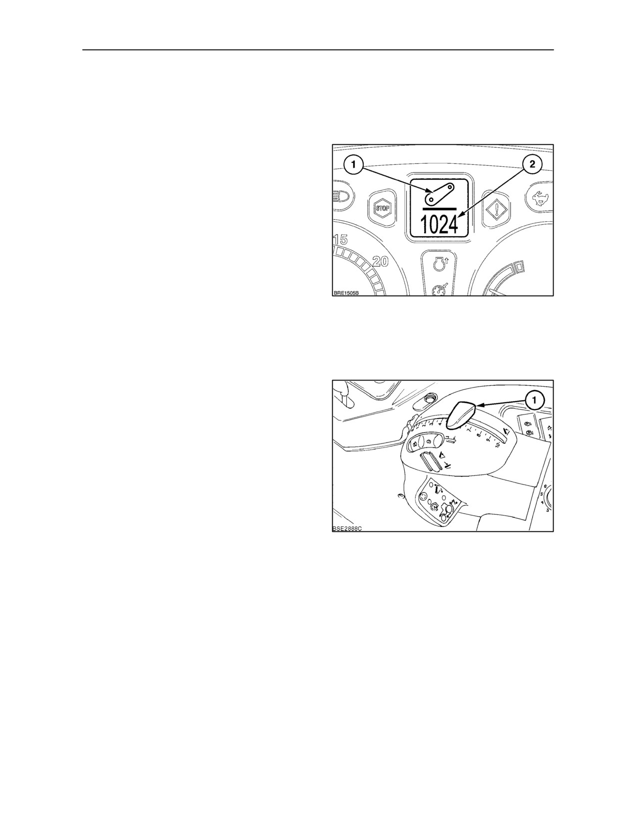
Malfunction Warning Light
In the unlikely event that a fault occurs in the EDC,
the malfunction warning light (1) Figure 81, will start
toflash. Thewarninglight will beaccompanied bythe
appearance of the hitch symbol (1), and error code
(2), in the Dot Matrix Display.
83
3--49
SECTION 3 -- FIELD OPERATION
The code indicates the tractor circuit or sensor in
which the fault lies and the type of fault, e.g. short
circuit, open circuit, sensor failure, etc. In this event
your tractor will require the attention of your
authorised dealer.
A steady malfunction warning light signifies ‘hitch
disabled’ which is repeated in the Dot Matrix Display
by the apperance of the hitch symbol (1) and error
code ’1024’ (2).
The ‘hitch disabled’ warning light signifies that the
position control setting does not correspond to the
position of the lower links with the result that the
lower links cannot be raised or lowered using the
in-cab controls. The ‘hitch disabled’ warning will
display if:
• The Position Control lever has been moved with
the engine stopped.
84
• One of the external power lift switches has been
operated to raise or lower the three-point linkage.
See ‘External Hydraulic Power Lift Controls’ on
page 3--57.
To put the Position Control lever back into phase with
the lower links, place the raise/lower switch in the
central position and, with the engine running, move
the Position Control lever
(1) slowly forward or
rearward, as required, until the position of the lever
matches the linkage height. The ‘hitch disabled’
warning light will go out and the hitch error symbol will
disappear from the Dot Matrix Display. The 3--point
linkage will now raise or lower normally.
85
3--50
SECTION 3 -- FIELD OPERATION
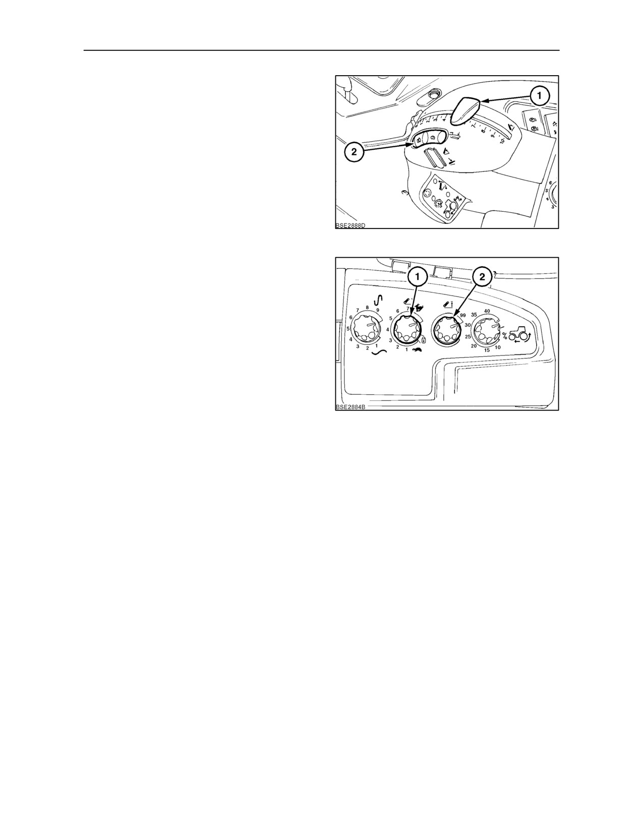
PRE--OPERATION SETTINGS
Attach the implement to the 3--point linkage.
Turn the draft loading wheel (2) fully forward to
position 10 -- this is the Position Control setting.
Start the engine and, using the Position Control lever
(1), raise the implement in stages, ensuring that
there is at least 100 mm (4 in.) clearance between the
implement and any part of the tractor. Note the digital
display reading on the instrument panel. If the
reading is less than ‘99’ it means that the implement
is not fully raised.
86
Adjust the height limit control knob (2) to prevent the
linkage being raised further and so avoid the
possibility of the implement damaging the tractor
when fully raised.
When the raise/lower switch or the Position Control
lever is used to raise the implement, it will only raise
to the height set by the height limit control, as
determined in the previous step.
Adjust the rate of drop, to suit the size and weight of
the attached implement, by rotating the drop rate
control knob (1). Turn the knob clockwise to speed up
the drop rate or anti-clockwise to slow down the drop
87
rate.
IMPORTANT: When first setting the implement up
for work, keep the drop rate control knob in the slow
drop position (‘tortoise’ symbol).
When the raise/lower switch is used to lower the
implement, it will lower at a controlled rate as
determined in the previous step.
3--51
SECTION 3 -- FIELD OPERATION
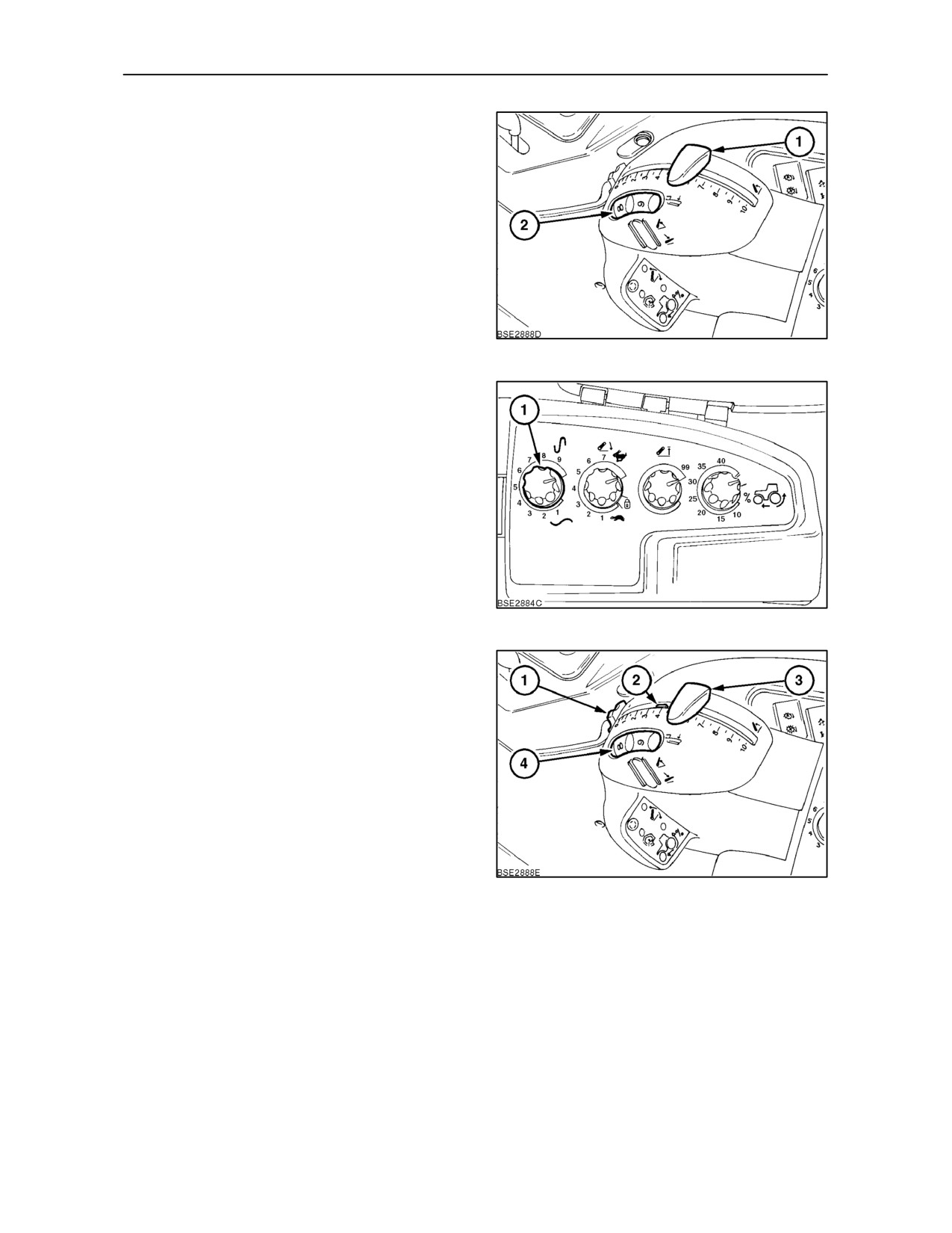
DRAFT CONTROL OPERATION
To operate in Draft Control adjustment of several
controls is necessary to suit the implement and field
conditions.
The draft loading wheel (2), determines implement
depth by setting a required force on the draft sensing
pins Set the wheel to the mid-position (position 5)
prior to commencing work.
88
The position of the draft sensitivity knob
(1),
determines the sensitivity of the system. Set the
knob to the mid-position before entering the field.
89
Drive the tractor into the field and lower the
implement into work by moving the Position Control
lever (3), forward. Use the Position Control lever to
set the maximum depth and so prevent ‘diving’ when
areas of light soil are encountered. Set the required
implement working depth by rotating the draft loading
wheel (4).
Rotate the thumbwheel (1) to move the adjustable
stop (2) against the Position Control lever so that the
selected setting may be quickly found.
90
3--52
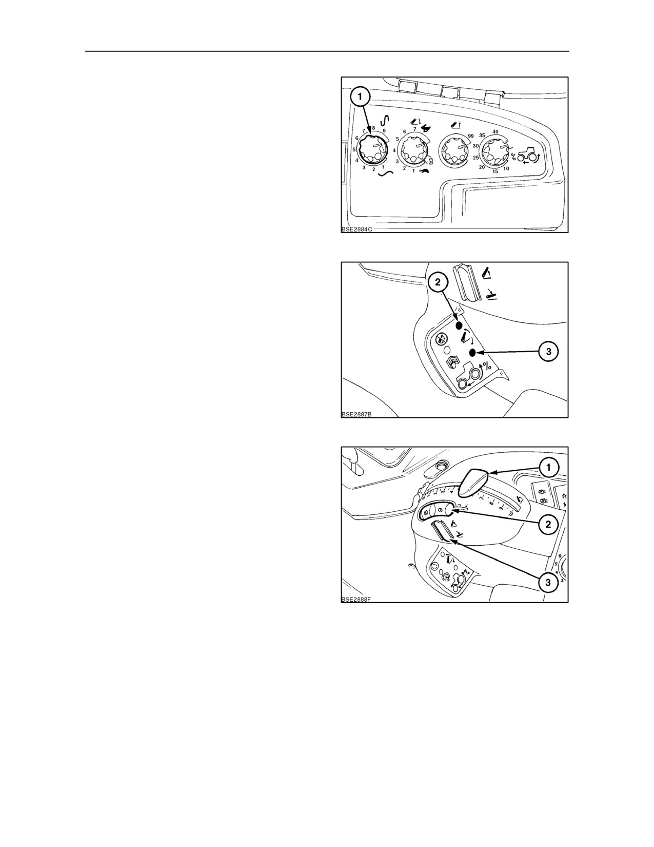
SECTION 3 -- FIELD OPERATION
Observe the implement as it pulls through the soil
and adjust the draft sensitivity knob (1), until the
tendency to raise or lower, due to variations in soil
resistance, is satisfactory. Once set, the tractor
hydraulic system will automatically adjust implement
depth to maintain an even pull (draft load) on the
tractor.
The optimum setting will be achieved by observing
the movement indicator lights (2) and (3). The upper
light (2) will illuminate every time the system raises
the implement as normal draft corrections occur. The
lower light (3) will illuminate as the implement lowers.
91
Turn the draft sensitivity knob (1) slowly clockwise.
The system will respond with smaller, quicker
movements as will be seen by both the indicator
lights flickering. At this point, turn the knob slightly
anti-clockwise until either of the indicator lights
flashes once every 2 or 3 seconds or, as required, to
suit the soil conditions.
Once the required working conditions have been
established there is no need to move the position
control lever again until the work in hand is
completed.
92
Upon reaching the headland, momentarily depress
the top of the raise/lower switch (3) to quickly lift the
implement to the position set by the height limit
control knob. When re-entering the working area,
momentarily depress the lower part of the switch and
the implement will descend at the rate set by the drop
rate control knob and stop when it reaches the depth
set by the draft loading wheel (2).
During the raise cycle, momentarily depressing the
top of the raise/lower switch will pause implement lift.
Depress the top of the switch again to resume the
cycle.
93
Depressing the lower part of the switch during the
lowering cycle will also pause implement drop.
3--53
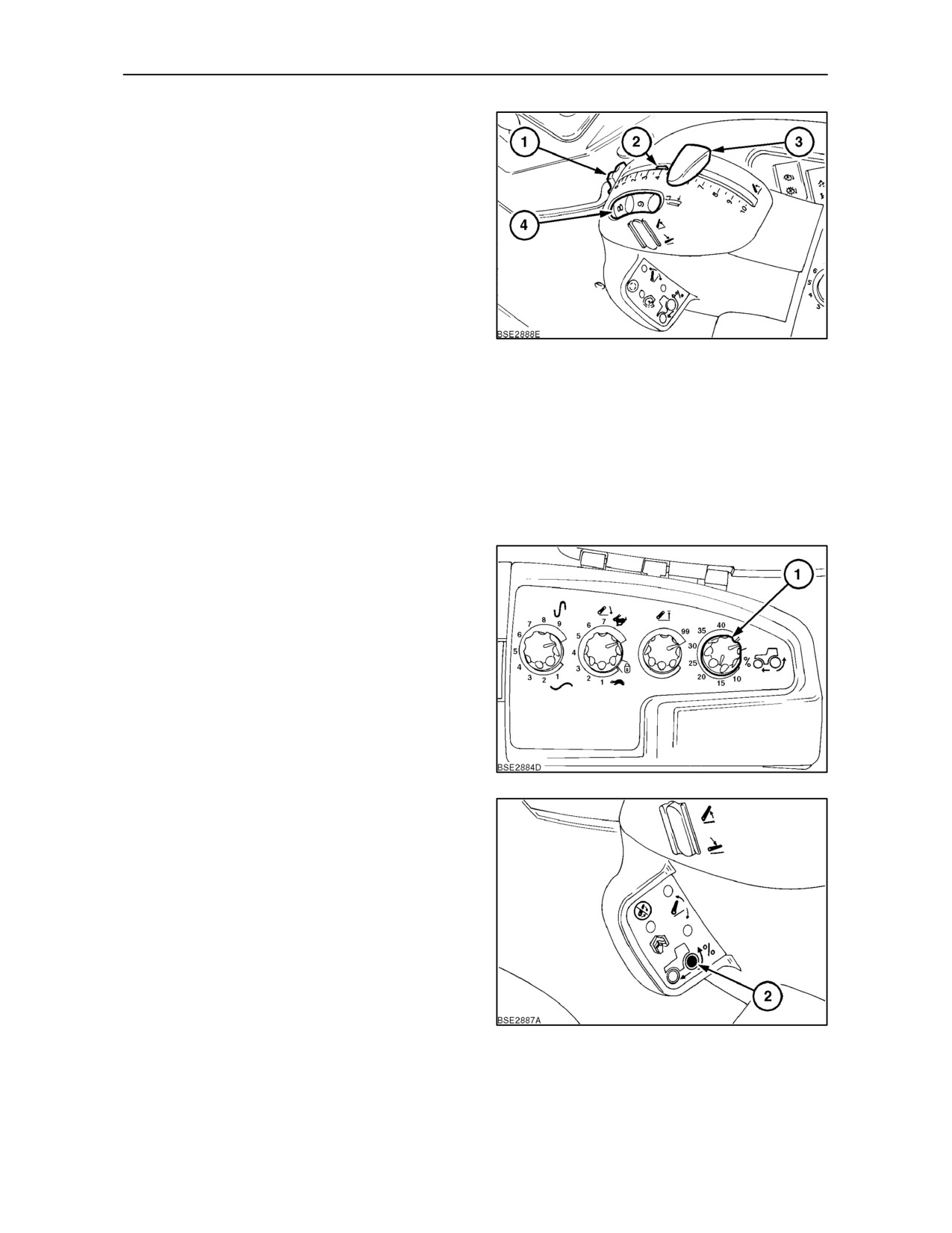
SECTION 3 -- FIELD OPERATION
Faster implement penetration may be required, for
example, after turning at a narrow headland. Also,
some implements are reluctant to penetrate,
particularly if the ground is heavy. Press and hold the
bottom of the raise/lower switch
(4) and the
implement will lower at the rate set by the drop rate
control knob, until it contacts the ground. The drop
rate and the Position Control settings will then be
overridden and the implement will quickly penetrate
the ground, rising to the preset working depth when
the switch is released.
Alternatively, the adjustable stop may be used to set
the implement depth. When the required implement
94
depth has been established, rotate the thumbwheel
(1). This will move the stop (2) so that it is against the
front edge of the position control lever (3). Whenever
the implement is raised, using the Position Control
lever, it will always return to the same working depth
when the lever is moved forward to contact the stop.
NOTE: If required, the Position Control may be
eased sideways (to the left), in order to bypass the
stop, to lower the implement further.
The slip limit control knob (1), available only with the
optional radar sensor unit, enables the operator to
select a wheel slip threshold, above which the
implement will raise until wheel slip returns to the
preset level. The system overrides the normal Draft
and Position Control sensing signals of the
hydraulics so care must be taken not to select too low
or too high a slip limit. Setting the slip limit to a very
low level, unobtainable in wet conditions, may have
a detrimental effect on the work rate/depth.
95
The slip limit ‘on’ indicator (2) will illuminate when slip
control is activated and the implement is raising to
restore the selected slip rate. The knob is detented
at the ‘off’ position (knob fully clockwise).
96
3--54
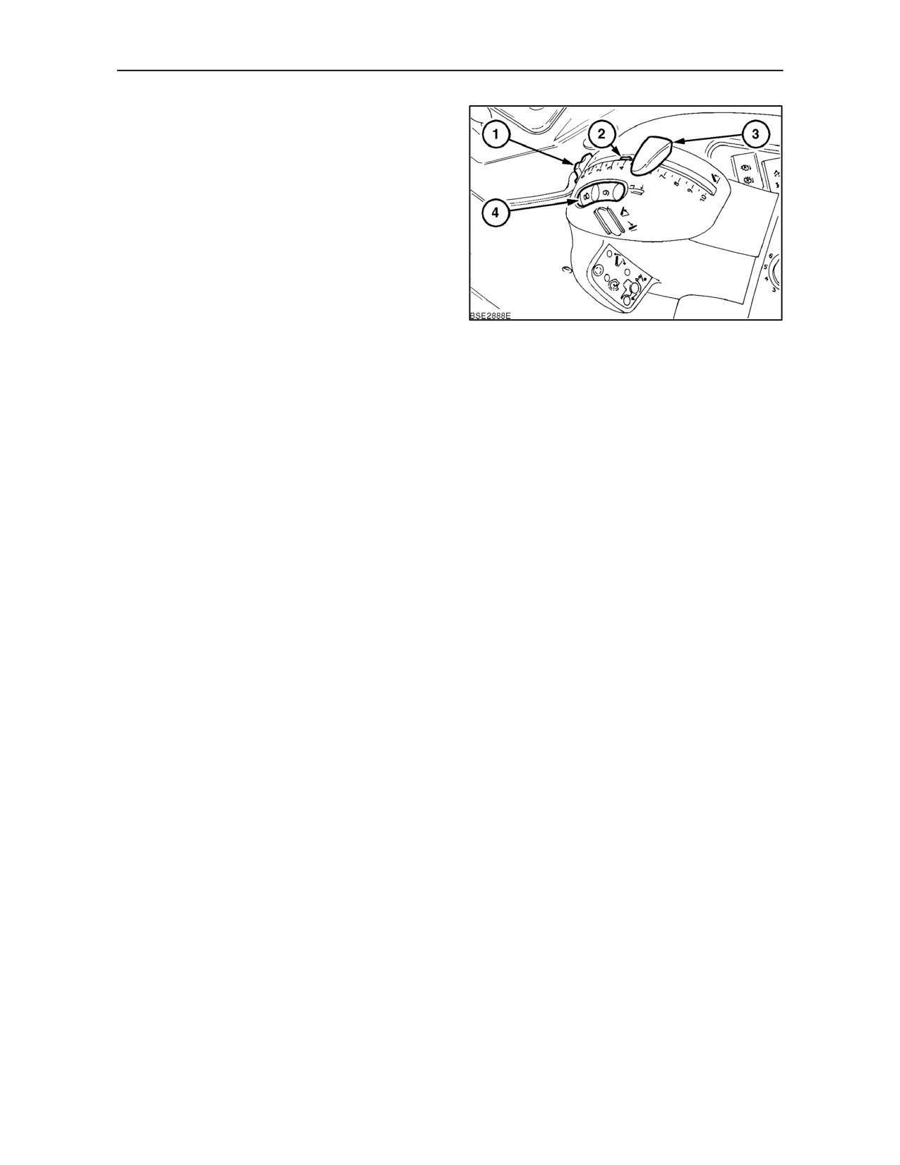
SECTION 3 -- FIELD OPERATION
POSITION CONTROL OPERATION
To operate in Position Control, the draft loading
wheel (4) should, ideally, be rotated fully forward to
position 10.
Use the Position Control lever (3) to raise and lower
the 3--point linkage. The implement will raise and
stop at the height set by the height limit control knob.
NOTE: The rate of lift will be adjusted automatically.
If a large movement of the position control lever is
made then the lower links will respond by moving
rapidly. As the links approach the position set by the
97
Position Control lever, implement movement will be
slower.
When the implement is at the required working
height, use thumbwheel (1) to set the adjustable stop
(2) against the Position Control lever (3). Every time
the Position Control lever is moved, it may be quickly
returned to it’s original position, against the stop, to
maintain the required implement height.
If it isrequiredtoraisetheimplementat theheadland,
momentarily depress the top of the raise/lower
switch (5), to lift the implement to the position set by
the height limit control knob. When re-entering the
work area, depress the lower part of the switch and
the implement will return to the height originally set
by the Position Control lever (3).
3--55
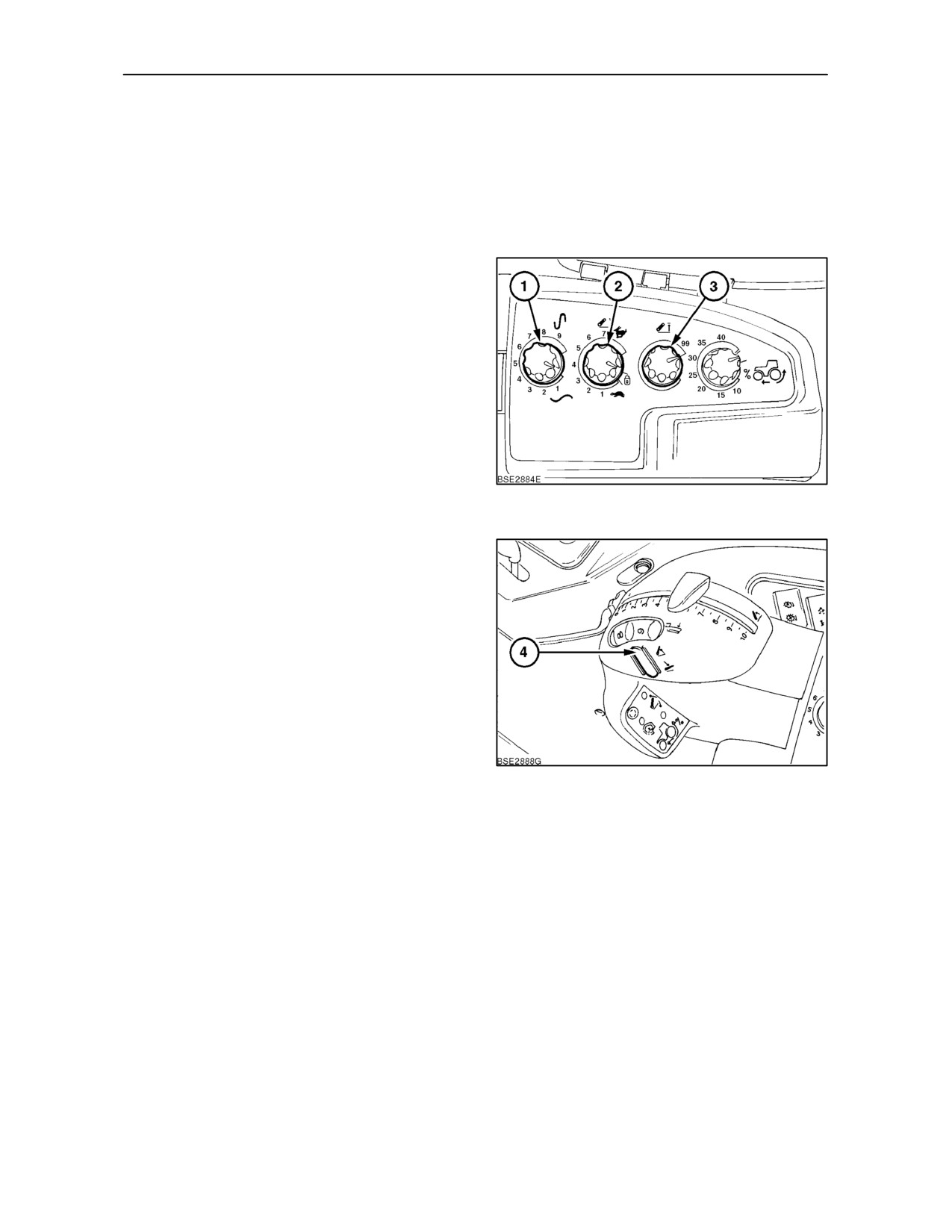
SECTION 3 -- FIELD OPERATION
TRANSPORT LOCK
When transporting equipment on the 3-point linkage,
turn the drop rate control knob (2), fully anti-clockwise
to the transport lock position (padlock symbol). This will
prevent the implement from accidentally lowering and
damaging the road surface.
DYNAMIC RIDE CONTROL
When transporting equipment on the 3-point linkage,
implement bounce can lead to lack of steering control
at transport speeds. With Ride Control selected,
when the front wheels hit a bump, causing the front
of the tractor to rise, the hydraulic system will
immediately react to counter the movement and
minimise implement bounce to provide a smoother
ride.
To engage Ride Control, turn the draft sensitivity
knob (1), fully anti-clockwise. Using the raise/lower
switch (4) Figure 99, raise the implement to the
98
height set by the height limit control (3).
Turn the drop rate control knob
(2) fully
anti-clockwise to the transport lock position (padlock
symbol).
Ride Control will only operate at speeds above 8 kph
(5 MPH). When tractor speed exceeds 8 kph (5 MPH),
the implement will drop by 4 -- 5 points (as displayed
on the instrument panel) as the hydraulic system
makes corrections to counteract implement bounce.
When tractor speed falls below 8 kph (5 MPH) the
implement will raise again to the height set by the
height limit control and Ride Control will become
inoperative.
99
3--56
SECTION 3 -- FIELD OPERATION
EXTERNAL HYDRAULIC POWER LIFT
CONTROLS (where fitted)
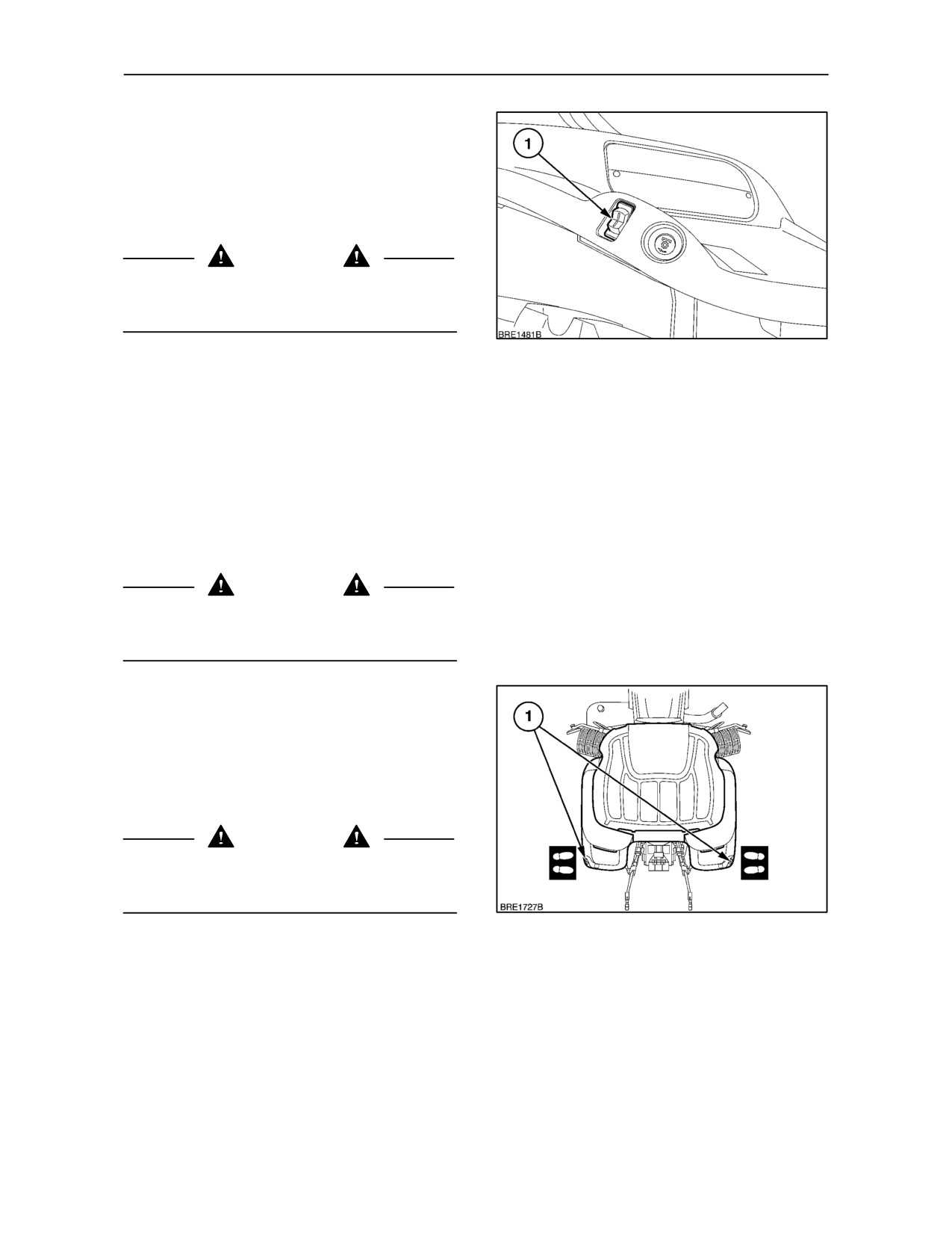
An external, rocker type switch (1) is provided on
each rear fender assembly. The switches are of a
three-position design, spring-loaded to return to the
central, off position.
WARNING
Do not stand on or near the implement or between
the implement and tractor when operating the
external hydraulic power lift controls.
100
Before leaving the tractor to operate the external
switches:
• Move the gearshift levers to neutral.
• Disengage the P.T.O.
• Apply the parking brake.
With the engine running, move the hand throttle lever
to the low idle position (fully rearwards).
WARNING
Before using the external hydraulic power lift
switches, ensure that no person or object is in the
area of the implement or 3-point linkage.
Never operate the external switches while standing:
• Directly behind the tractor or tyres.
• Between the lower links.
• On or near the implement.
WARNING
Never extend arms, legs, any part of the body or any
object into the area near the 3-point linkage or
implement while operating the external switch.
101
3--57
SECTION 3 -- FIELD OPERATION
Never have an assistant working the opposite set of
controls. When moving to the opposite set of
controls, move around the tractor or implement. Do
not cross between the implement and tractor.
The operator must only activate the external
switches while standing to the side of the tractor
(outboard of the rear tyres).
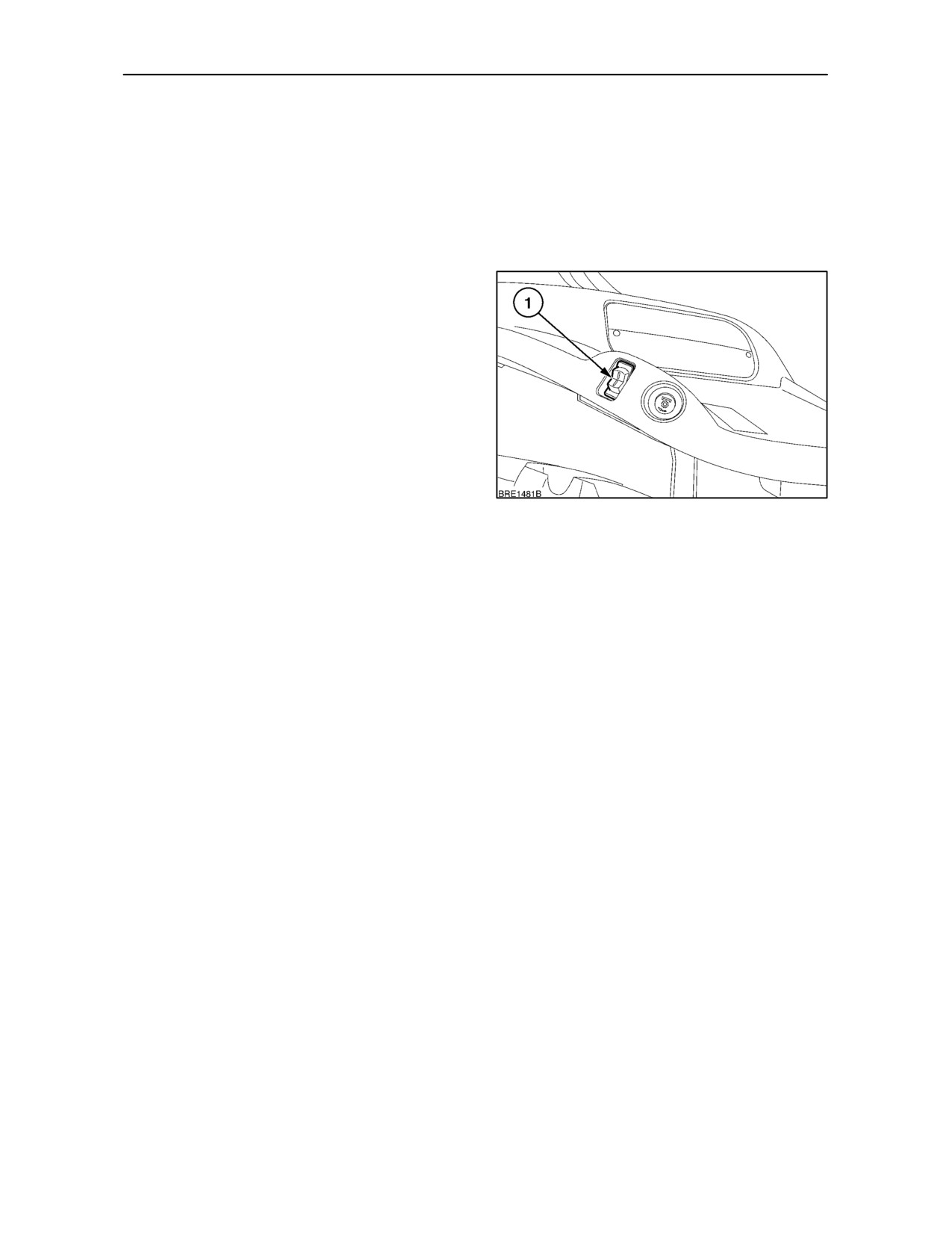
Pressing the upper part of the rocker switch (1) will
cause the lift linkage to raise slowly. Pressing the
lower part will cause the linkage to lower. When the
lower links align with the implement, release the
switch and attach the implement to the 3-point
linkage in the normal way.
To transfer control of the hydraulic power lift back to
the lift control lever, move the lift control lever fully
rearwards and push forward again, more slowly. The
‘hitch enabled’ symbol will display in the instrument
panel, indicating that the 3-point linkage is in phase
with the lift control lever (see page 3--50).
102
IMPORTANT: When control of the 3-point linkage is
transferred back to the lift control lever, an attached
implement may raise fully and damage the rear of the
cab. Operator’s should be aware of this and take
appropriate action to stop raising before full lift height
is reached. Adjust the height limit control knob as
described under Position Control Operation.
3--58
SECTION 3 -- FIELD OPERATION
HYDRAULIC REMOTE CONTROL VALVES
WARNING
Hydraulic fluid escaping under pressure can
penetrate the skin causing serious injury. If any fluid
is injected into the skin, obtain medical attention
immediately or gangrene may result.
• Do not use your hand to check for leaks. Use a
piece of cardboard or paper.
• Stop the engine and relieve pressure before
connecting or disconnecting hydraulic lines.
• Tighten all connections before starting the
engine or pressurising lines.
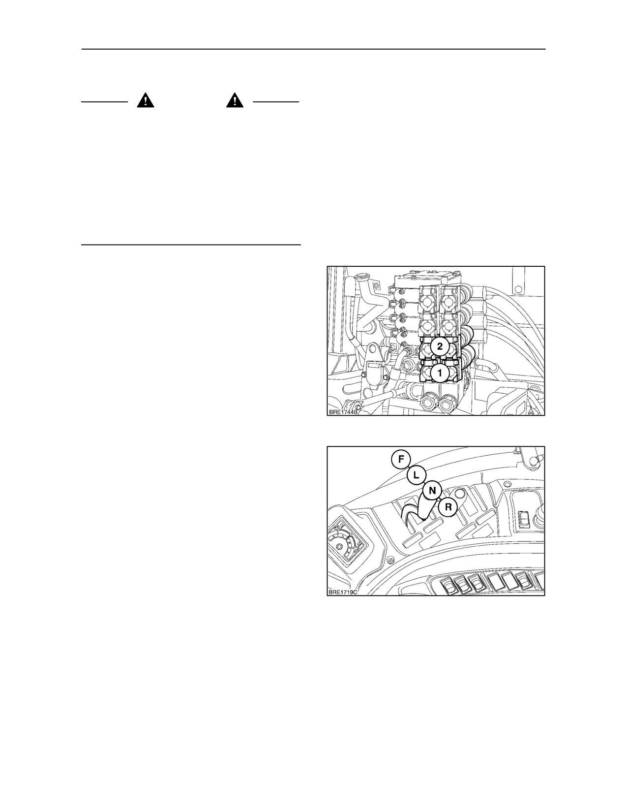
Hydraulic remote control valves are available to
operate external hydraulic cylinders, motors etc. All
models have two valves as standard, installed at the
rear of the tractor adjacent to the top link.
On tractors with four valves, the first and second
valves may be controlled by levers or by a 4--way
joystick control mounted to the right of the operator’s
seat.
Each control lever is coloured to correspond to the
colour marking on the remote valve.
103
Control Levers
Each valve is controlled by a separate lever providing
four operating positions, raise (R), neutral (N), lower
(L) and float (F). The levers and their respective
valves are colour coded for identification.
Move the lever rearward from the neutral position
and the cylinder will extend to raise the implement.
Push the lever forward, past neutral, to retract or
lower the cylinder. Pushing it fully forward, beyond
the ‘retract’ position, will select
‘float’ which will
permit the cylinder to extend (raise) or retract (lower)
freely, thereby allowing equipment such as scraper
104
blades to ‘float or follow the ground contour.
3--59
SECTION 3 -- FIELD OPERATION
Joystick Control (where fitted)
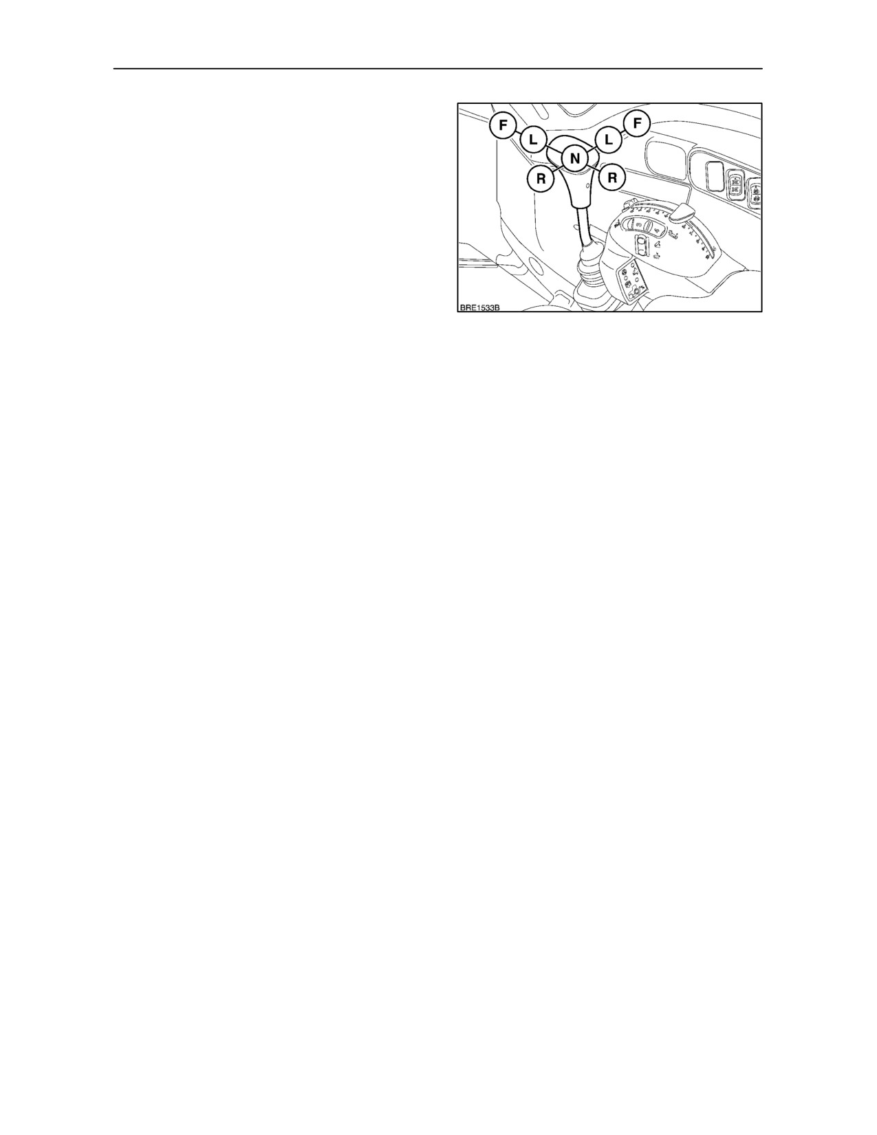
The joystick (1), actuates valves I and II, operating
in a cross pattern.
Moving the joystick backwards and forwards in a
straight line actuates valve No. I.
Moving the joystick sideways in a straight line
actuates valve No. II.
Moving the joystick diagonally will actuate both
valves simultaneously. By applying directional bias,
one valve can be made to actuate at a faster or
105
slower rate than the other.
Move the joystick rearward from the neutral position
and the cylinder connected to valve No. I will extend
to raise the implement. Push the joystick forward,
past neutral, to retract (lower) the cylinder. Pushing
it fully forward, beyond the ‘retract’ position, will
select ‘float’ which will permit the cylinder connected
to remote control valve No. I to extend or retract
freely, thereby allowing equipment such as scraper
blades to ‘float or follow the ground contour.
Move the joystick to the left from the neutral position
and the cylinder connected to valve No. II will extend
to raise the implement. Move the joystick to the right,
past neutral, to retract the cylinder. Move the it fully
to the right, beyond the ‘retract’ position, will select
‘float’ which will permit the cylinder connected to
remote control valve No. II to extend or retract freely.
The joystick and it’s respective valves are colour
coded for identification.
3--60
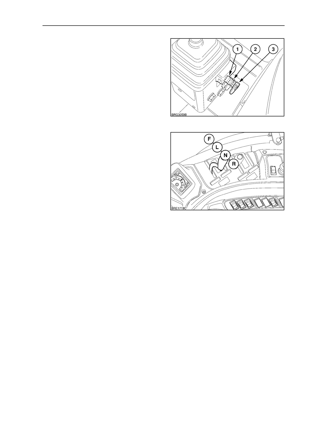
SECTION 3 -- FIELD OPERATION
Joystick Lock
The lever lock provides selective control of the
joystick. With the lock pushed fully in, position (1), the
joystick is fixed in neutral and the remote valves
cannot be operated, either by accident or by choice.
If the lock is pulled fully out, position (3), valves I and
II may be operated independently or together by
moving the joystick control in the appropriate
direction.
Intheintermeadiateposition (2), lateral movement of
the joystick that operates valve II is locked.
106
Joystick or Lever Controls
The extend (raise), neutral, retract (lower) and float
positions are identified by symbols on a decal next to
the joystick and/or control levers.
A detent will hold the joystick/lever in the selected
extend or retract position until the remote cylinder
reaches the end of the stroke when the control lever
will automatically return to neutral. Alternatively, the
lever may be returned to neutral manually. The lever
will not return automatically from the float position.
NOTE: Do not hold the joystick/lever in the extend or
107
retract position once the remote cylinder has
reached the end of the stroke as this will cause the
relief valve to ‘blow’. Forcing oil through the relief
valve for extended periods will overheat the oil and
may lead to failure of hydraulic and driveline
components.
3--61
SECTION 3 -- FIELD OPERATION
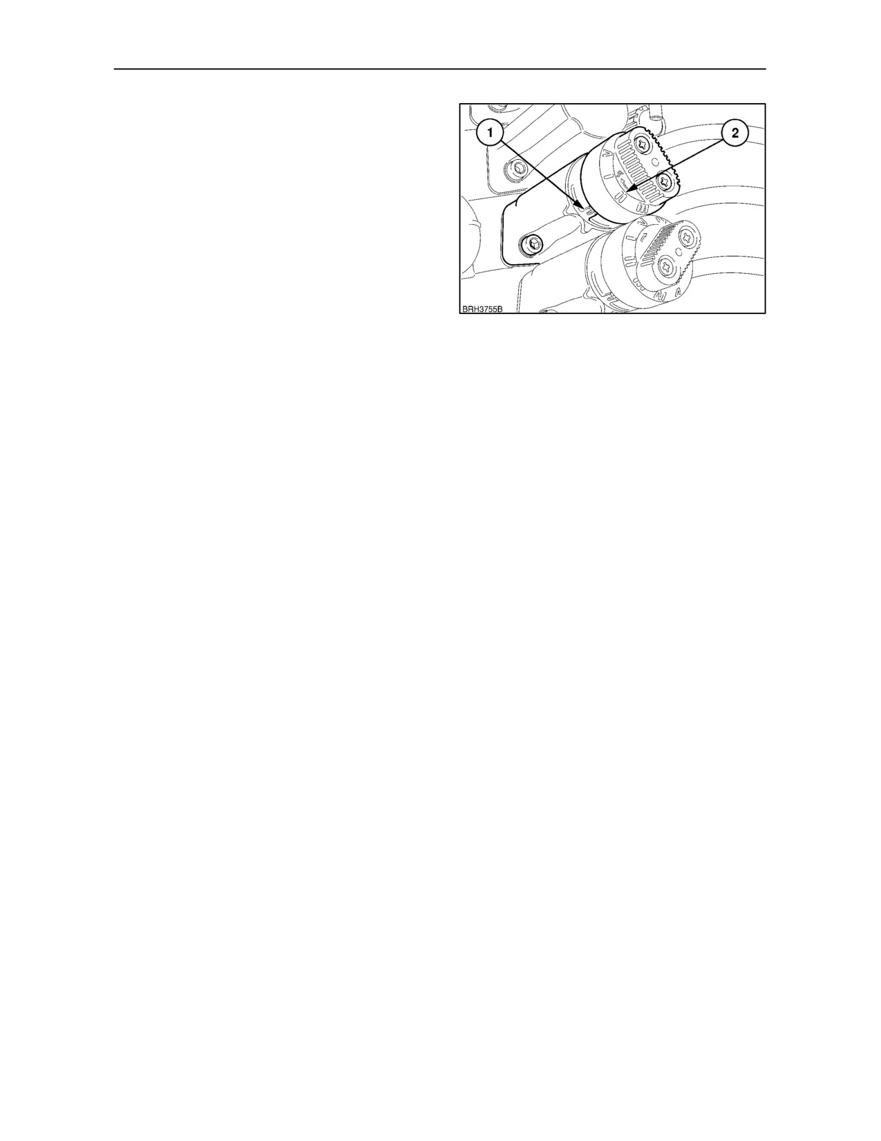
Configurable Detent Operation
(where fitted)
Your tractor may be fitted with two remote valves
having configurable detents. The rotary control (1),
is used to select one of five detent settings.
To select a setting, rotate the control until the number
(2), on the end cap, aligns with the mark (1), on the
valve body.
NOTE: If the number on the rotary control is not
aligned correcty with the reference mark on the valve
body, the performance of the valve may be affected.
108
Before turning the selector, ensure any residual
pressure in the hydraulic system is exhausted. To do
this, stop the tractor engine, cycle the remote valve
lever through all positions and then place the lever in
neutral.
Each position offers the follwing functions:
I.
Raise (R), Neutral (N), Lower (L) and Float (F)
*To select position 5, place the remote valve lever in
positions available.
neutral, select position I or IV then move the lever to
Detent position in Float only.
the Float position. With the lever in Float select
No lever auto return to neutral (kick out).
position V.
II. Raise, Neutral and Lower positions only.
To de--select position V, put the remote valve lever
No Float facility.
into float, turn the selector control to position I or IV
No detent positions available.
and then move the remote valve lever to neutral. It
No lever auto return to neutral (kick out).
is now possible to select positions I to IV.
III. Raise, Neutral, Lower and Float positions
IMPORTANT: To prevent inadvertent movement of
available.
attached equipment when starting the tractor engine,
Detents in Raise, Lower and Float.
ensure the remote valve levers are in the correct
Lever auto return to neutral (kick out) in Raise
position before operating the key--start switch:
and Lower positions.
With the selector in positions I to IV -- Neutral
With the selector in position V -- Float
IV. Raise, Neutral, Lower and Float positions
available.
Detents in Raise, Lower and Float.
No lever auto return to neutral (kick out).
V. *Raise and Float positions available.
Detents in Raise and Float.
No lever auto return to neutral (kick out).
3--62
SECTION 3 -- FIELD OPERATION
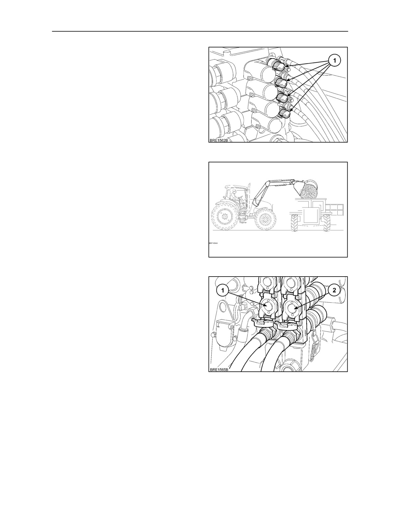
Flow Control
The flow control valve (1), meters the flow of oil to the
remote cylinder and thus controls the rate of
response of the cylinder. Rotate the flow control
anti--clockwise to increase the oil flow to the
implement, rotate clockwise to reduce the oil flow.
For flow rates, see Section 8 -- Specifications.
109
Operating with a Front Loader
If your tractor is fitted with a non New Holland front
loader, the rear remote valves may be used to
provide the hydraulic power.
For loader control it is recommended that remote
valves 1 and 2 are fitted with a joystick and converted
to non detent operation (position 1 with adjustable
detents).
See Accessories, Section 7 for details on Zero
Detent kits for non adjustable remote valves
110
Remote Valve Couplers
Each remote control valve has a pair of1/2 in.
quick-disconnect, female couplers. These are of a
self--sealing/locking design but will allow remote
cylinder hoses to pull free if the implement should
become disconnected from the tractor. The raise (lift)
coupler (1), is on the left--hand side, the lower (drop)
coupler (2), on the right--hand side.
The flip--up covers are colour coded black, brown,
blue and green to corresponding to the control levers
in the cab.
111
3--63
SECTION 3 -- FIELD OPERATION
Connecting Remote Cylinders
WARNING
Before connecting or disconnecting hydraulic hoses
at the remote cylinders, stop the engine and relieve
the pressure in the circuit by moving the remote
control valve lever(s) or joystick fully forward to the
‘float’ position then back to neutral. Never work under
or allow anyone near raised equipment as it will drop
when relieving pressure in the system.
WARNING
Before disconnecting cylinders or equipment ensure
the equipment or implement is supported securely.
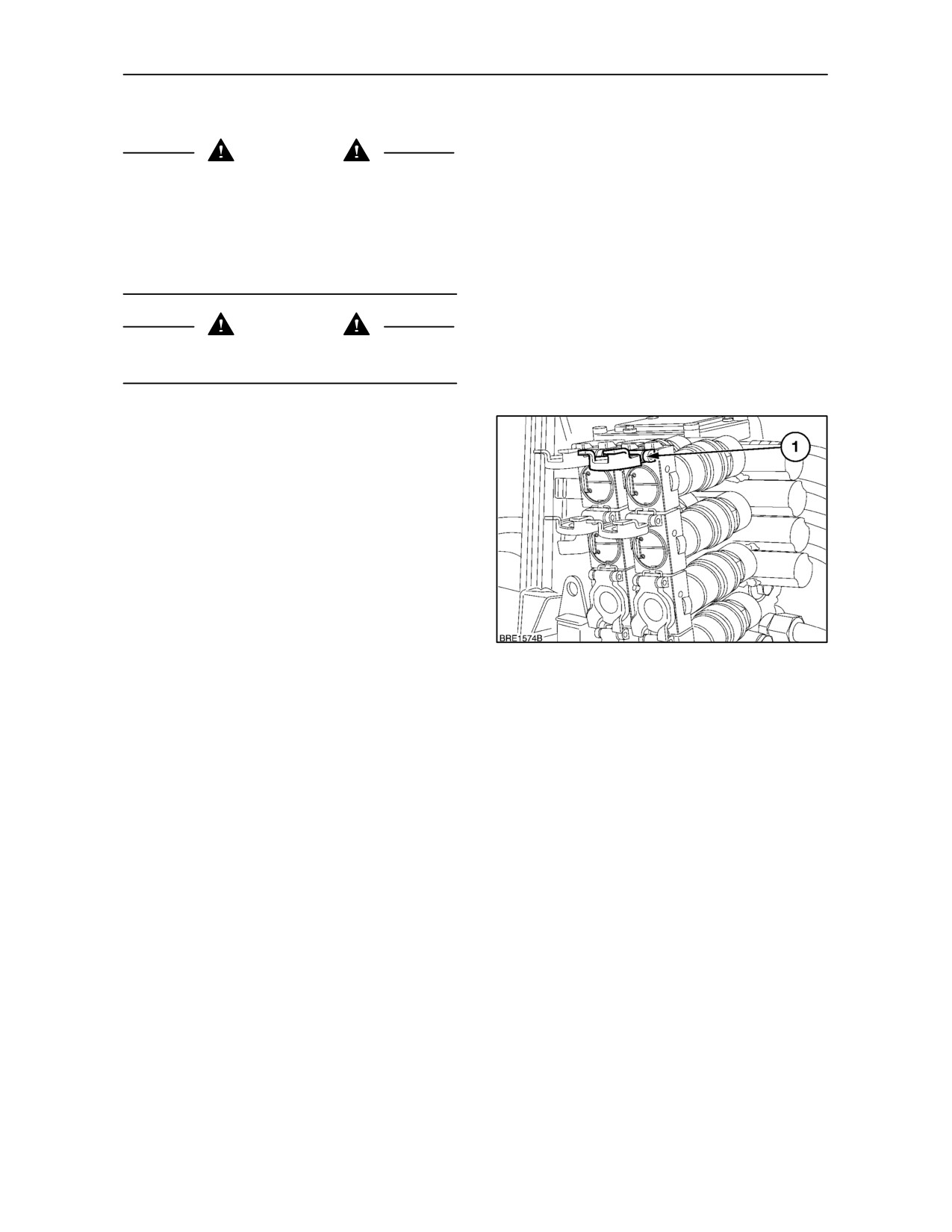
To connect a remote cylinder, lift the hinged cover(1),
until it locks in the raised position, insert the feed
and/or return hose through the slit in the secondary
dust cover, ensuring it is correctly seated in the
coupler. Ensure that there is sufficient slack in the
hose(s) to allow the tractor/implement to turn in
either direction.
IMPORTANT: Before connecting remote cylinder
hoses, stop the engine and thoroughly clean the
connections to prevent oil contamination.
112
3--64
SECTION 3 -- FIELD OPERATION
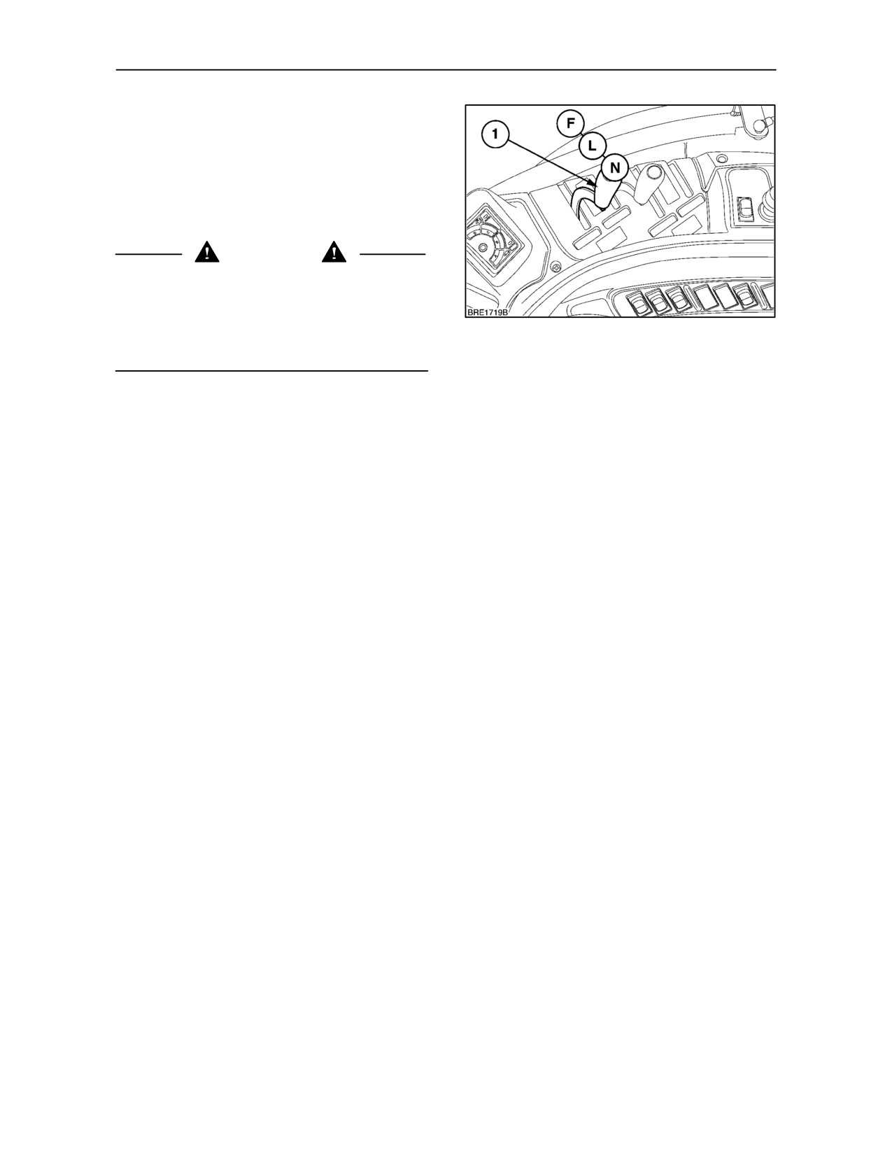
To equalise the pressure in the hose and tractor
couplers, start the engine and move the joystick or
valve control lever (1), to the ‘float’ position, then
return it to neutral. To disconnect, grip the hose a
short distance from the coupler, push the hose
forward, into the coupler, then quickly pull on the
hose to ‘pop’ the coupler free. Close the hinged cover
to protect the valve.
WARNING
Never work under equipment supported by a
hydraulic device because it may drop if the control is
actuated (even with the engine stopped) or in the
event of hose failure. Always use a secure support
113
for equipment which must be serviced while in the
raised position.
NOTE: Remote cylinders are operated by oil drawn
from the tractor hydraulic system, therefore, always
check and replenish the hydraulic system oil after
remote cylinder equipment has been connected and
cycled a few times. Operating the tractor with a low
oil level may result in damage to the rear axle and
transmission components.
When topping up the rear axle to accommodate the
requirement of remote cylinders, no more than 20
litres (5.28 U.S. Gallons) should be added to bring
the oil level up to the full mark on the dipstick.
Alternatively, remote cylinders with a total oil
capacity of up to 18 litres (4.75 U.S. Gallons) may be
connected to the tractor hydraulic system without
adding oil, provided that the tractor is being operated
on level ground.
3--65

SECTION 3 -- FIELD OPERATION
Operating Double-Acting Cylinders
Connect the feed hose (1) between the piston end of
a double-acting cylinder and the left--hand coupler on
the remote control valve. Connect the hose (2)
between the right--hand coupler on the same valve
and the rod end of the cylinder. To extend a
double-acting cylinder, move the control lever or
joystick to the ‘extend’ (raise) position.
To retract a double-acting cylinder, move the control
lever or joystick through neutral to the ‘retract’ (lower)
position.
114
Further movement of the lever or joystick, beyond
the ‘retract’ position, will select ‘float’ which will allow
the cylinder to extend or retract freely. This feature
is of material assistance when carrying out work with
equipment such as scraper blades and loaders.
115
Operating Single-Acting Cylinders
Connect the hose (1) from a single-acting cylinder to
the left--hand coupler (2) on the remote control valve.
To extend a single-acting cylinder, move the control
lever or joystick to the ‘extend’ (raise) position.
Manually return the lever or joystick to the neutral
position to stop the cylinder before it is fully extended
or allow the valve to return to the neutral
automatically when the cylinder reaches the end of
it’s stroke.
116
To retract a single-acting cylinder, move the lever or
joystick beyond the ‘retract’ (lower) position to the
‘float’ position.
3--66
SECTION 3 -- FIELD OPERATION
IMPORTANT: Always use the ‘float’ position to
retract a single-acting cylinder. The ‘retract’ position
is for double-acting cylinders only.
NOTE: If a single-acting cylinder is disconnected in
the extended position, while supporting a load, the
hose may be reconnected to the remote control valve
but will not operate until the pressure is released.
Proceed as follows:
• Connect the hose, as described above.
• Start the engine and momentarily pressurise the
cylinder by moving the remote control valve
117
lever/joystick to the extend position and then
immediately to the float position to retract the
cylinder and lower the implement.
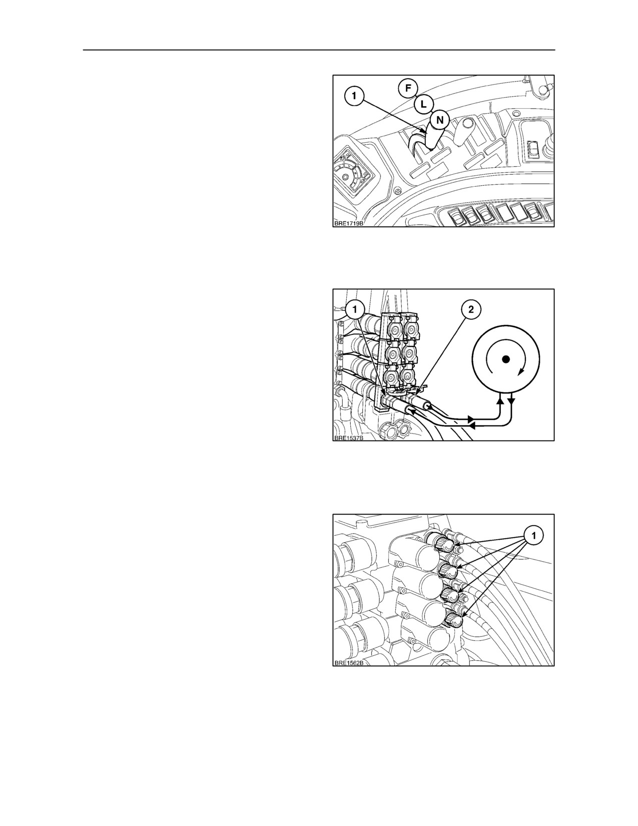
Operating Continuous Flow Hydraulic
Equipment
Continuous flow hydraulic equipment (e.g. hydraulic
motors) should be connected to a remote control
valve coupler with the feed hose (2) connected to the
right--hand coupler and the return hose
(1)
connected to the left--hand coupler of the same
valve.
With the remote control valve lever or joystick in the
‘float’ position the motor will be stationary. The
hydraulic motor will operate if the lever or joystick is
moved to the ‘retract’ (lower) position.
118
IMPORTANT: To stop the motor, move the lever or
joystick to the ‘float’ position. The motor will then slow
to a halt and not stop abruptly causing internal line
pressures which could damage the motor seals.
Observe the following to further protect the tractor
and equipment:
• Do not open any by-pass valve in the equipment
or motor. Use the flow control valve to control the
rate of flow or speed of the motor.
• To assure optimum hydraulic oil cooling and
prevent overheating, operate continuous flow
equipment at the highest flow setting (by use of
the flow control valve (1), and lowest engine
speed that will give the required machine
performance and speed.
119
3--67