New Holland TX62, TX63, TX64 Plus, TX65 Plus, TX66, TX67, TX68, TX68 Plus. Operator's Manual - page 3

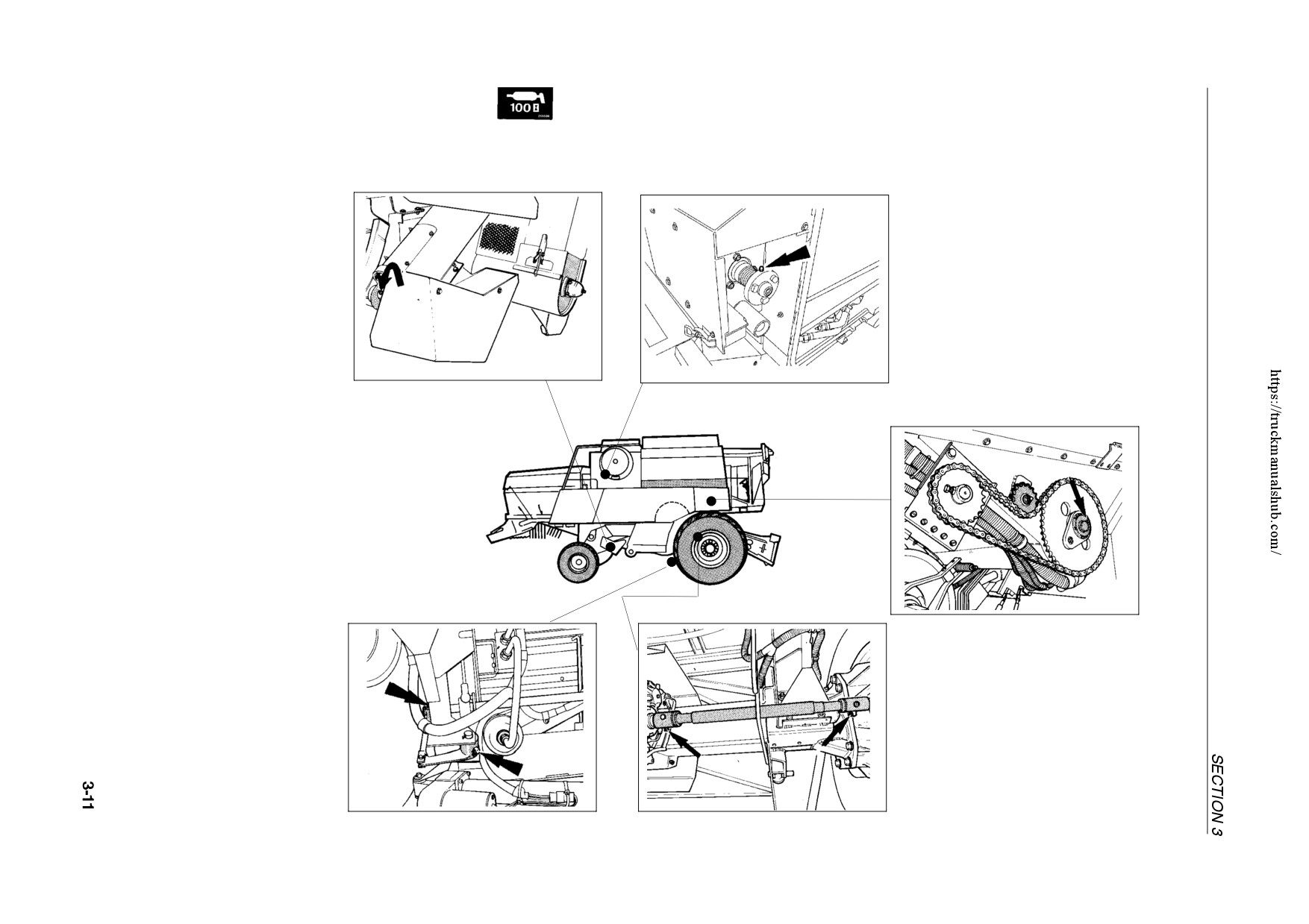
100 hour intervals -- Left-hand side
Left-hand half-shaft coupling
(gearbox side)
Left-hand half-shaft coupling (wheel side)
42803
42796
48
49
Left-hand returns auger drive gearbox
Chaff spreader gearbox
42795
43202
51
50
100 hour intervals -- Right-hand side
Right-hand returns auger drive gearbox
(TX66, TX67, TX68 and TX68PLUS)
Rotary dust screen coupling
42793
54720
52
53
Unloading auger drive shearbolt bushing
Gearshift linkage (2)
[view from underneath]
42807
(Not for TX67)
Right-hand half-shaft couplings (2)
54
42946
42799
56
55
LUBRICATION
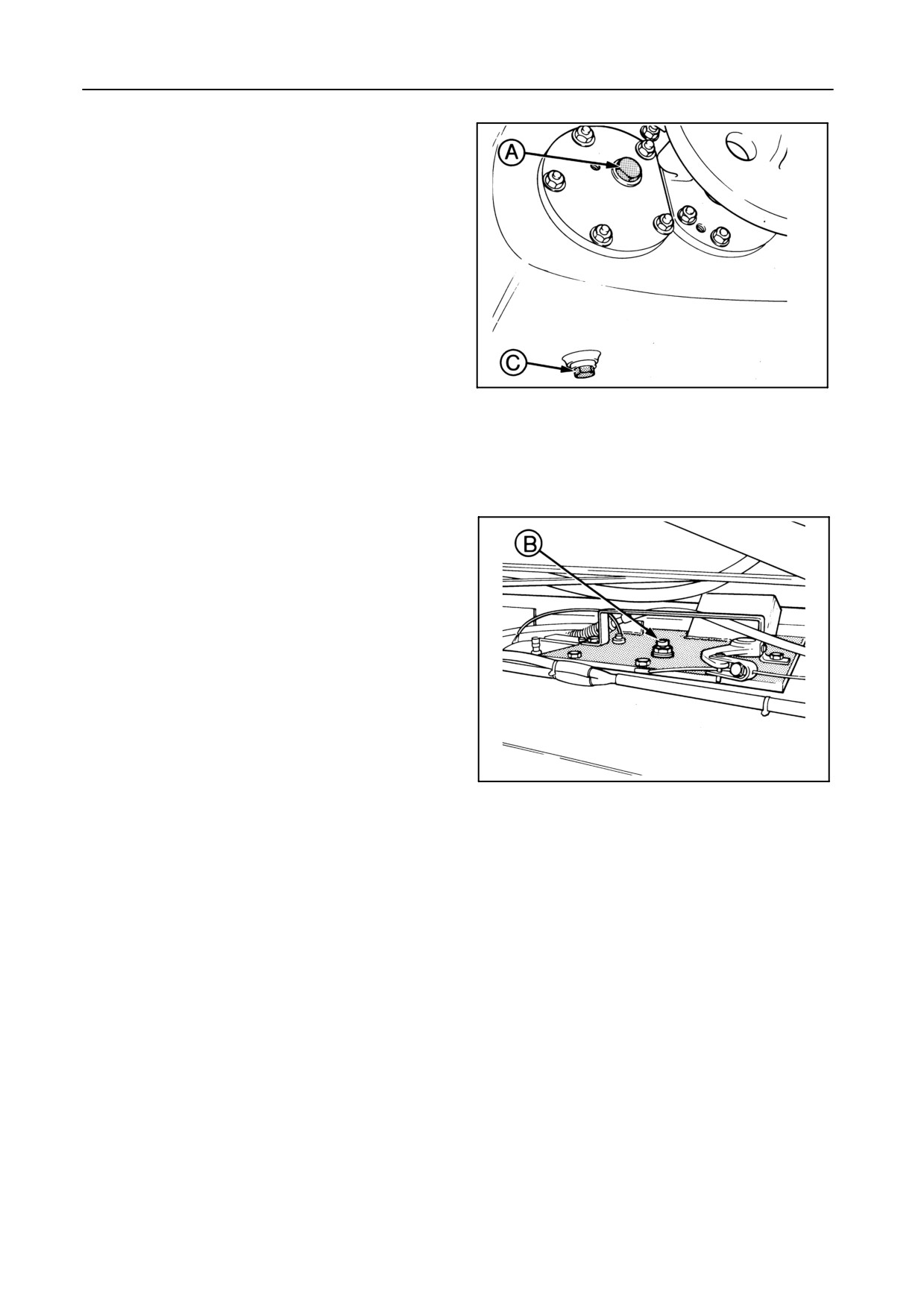
TRACTION GEARBOX -- Figures 57 and 58
Oil level
With the combine standing on a level surface, the oil
level should reach plug A on the right-hand side.
If necessary, add gear oil through the filler/breather
plug B after removing the gearbox cover plate.
42800
57
Oil change
S After the first 100 operating hours
S After 200 operating hours
S Thereafter, every 400 operating hours or annu-
ally.
Drain the oil through plug C.
Plug C is fitted with a magnet which should be cleaned
at every oil change.
42810
58
Gearbox capacity
15 litres
Oil specification
Use AMBRA HYPOIDE 90 gear oil (ref. NH520A) or
an oil meeting the following specification:
S API GL5 or MIL-L 2105D
S Viscosity grade: SAE 80W90
3-12
SECTION 3
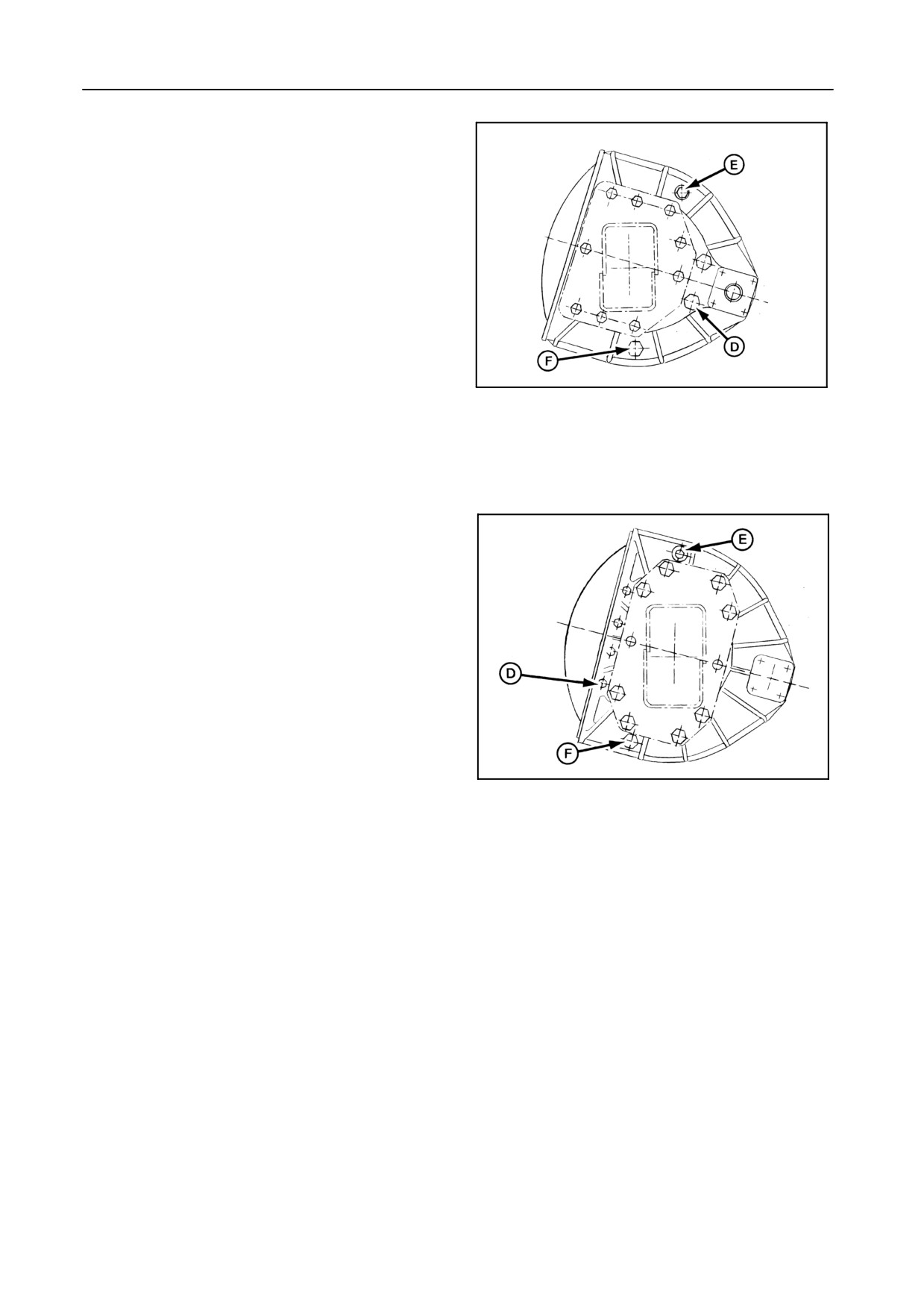
FINAL DRIVE GEARBOXES -- Figures 59 and 60
TX62-63-64PLUS-66
Oil level
With the combine standing on a level surface, the oil
should reach plug D.
If necessary, add gear oil through the filler/breather
plug E.
52028
59
Oil change
S After the first 100 operating hours
S After 200 operating hours
TX65PLUS-67-68PLUS
S Thereafter, every 400 operating hours or annu-
ally.
The oil can be drained through plug F.
Plug F is fitted with a magnet which should be cleaned
when changing the oil.
Gearbox capacity
52736
60
Models TX62-63-64PLUS-66:
5 litres (each gearbox)
Models TX65PLUS-67-68-68PLUS:
6 litres (each gearbox)
Oil specification
Use AMBRA HYPOIDE 90 gear oil (ref. NH520A) or
an oil meeting the following specification:
S API GL5 or MIL-L 2105 D
S Viscosity grade: SAE 80W90
3-13
LUBRICATION
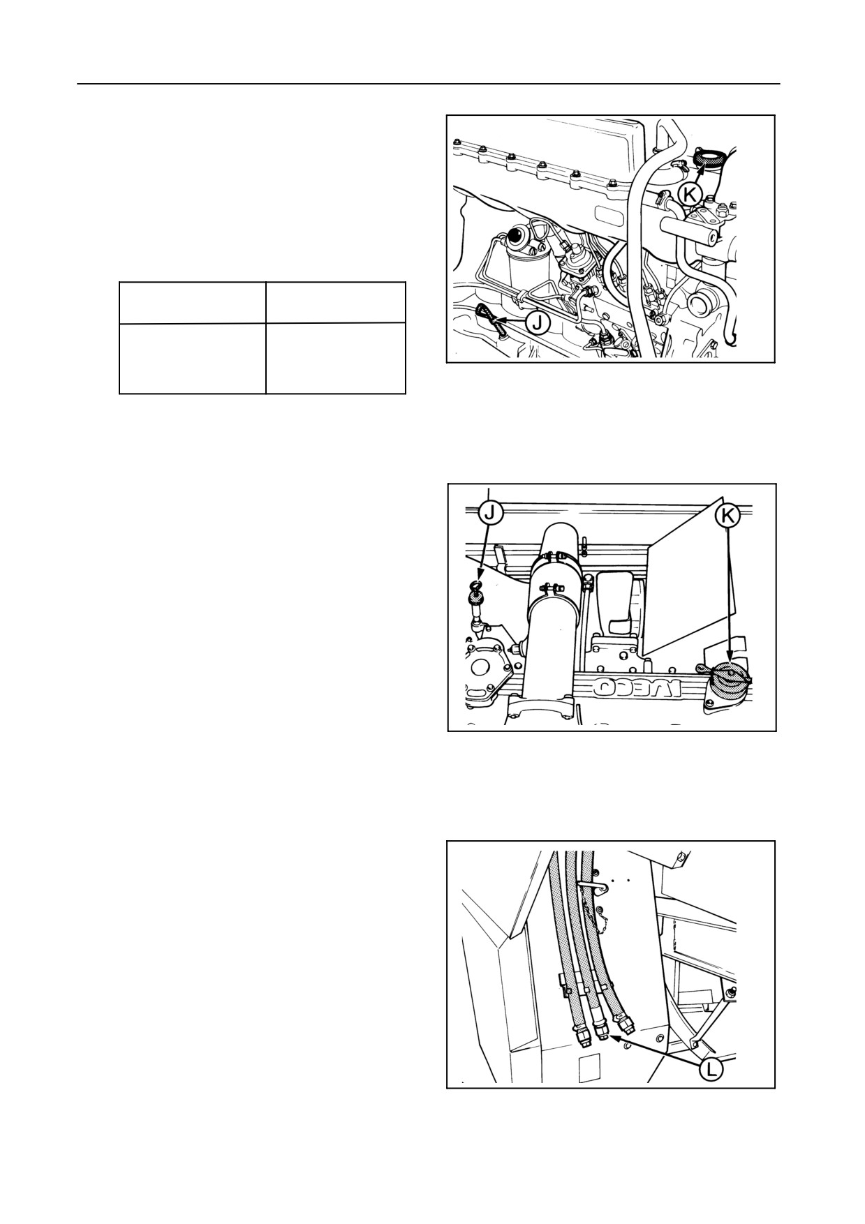
ENGINE -- Figures 61 to 64
NOTE:
Fuel sulphur content
Use fuel with a sulphur content below 0.5%.
If not available, change oil and filter(s) as de-
tailed below:
Fuel sulphur content
Oil filter change
0.5% -- 1 %
100 hours
42954
1% -- 1.3 %
50 hours
61
TX62-63-64PLUS-65PLUS-66-67
Use of fuel with sulphur content above 1.3 % is
not recommended.
Oil level
Check the oil level daily on dipstick J.
If necessary, add oil through filler hole K until the oil
reaches the maximum mark on dipstick J.
IMPORTANT:
At no time should the oil level be allowed to fall
below the minimum level.
42808
62
TX68-68PLUS
Recommended oil and filter change intervals
S After the first 50 operating hours
S Every 200 operating hours when using API CD/
SF oil (*)or
S Every 300 operating hours when using API
CF-4/SG oil (*)
(*) See paragraph headed ‘‘Oil specification’’ below.
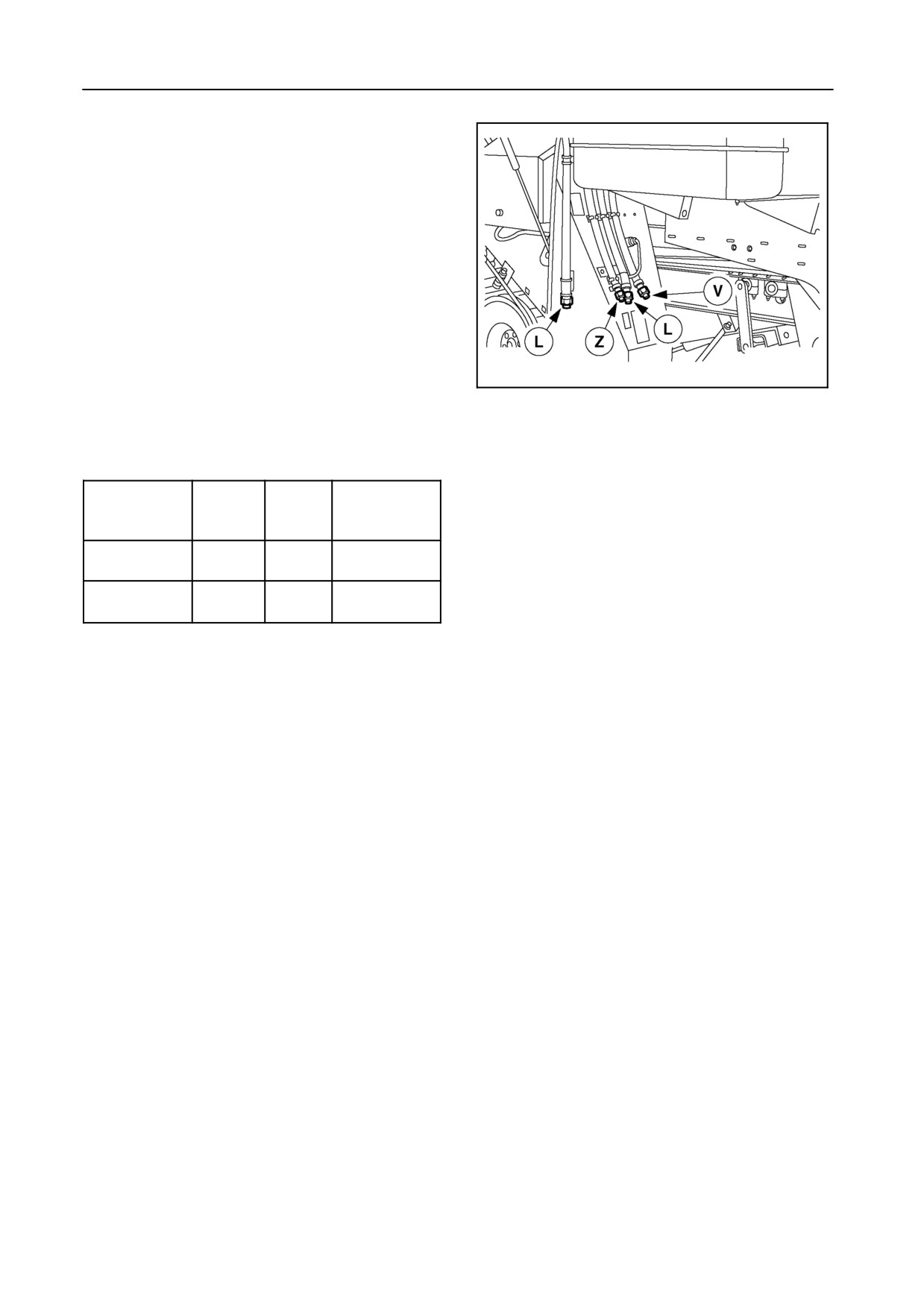
Drain the oil through hose L while the engine is mod-
erately warm and refill through filler hole K.
Refer to paragraph headed ‘‘Filter change’’ below.
42809
Check the oil level on dipstick J.
63
TX62-63-64
PLUS-65PLUS-66-67
3-14
SECTION 3
54621
64
TX68-68PLUS
Engine sump and filter capacity (litres)
Total
(filters
Model
Sump
Filters
and tubes
included)
TX62-63-64PLUS
21
1x1
23
65PLUS-66-67
TX68-68PLUS
Min: 15
2 x 1.5
24.5
Max: 20
Oil specification
a) 200 hours interval
Use AMBRA PREMIUM MULTIGRADE engine oil
(ref. NH330B) or an oil meeting the following specifi-
cation:
S API CD/SF or MIL-L 2104D
S Viscosity grade: 15W40
b) 300 hours interval
Use AMBRA SUPERGOLD MULTIGRADE engine oil
(ref. NH330G) or an oil meeting the following specifi-
cation:
S API CF-4/SG, CCMC D4 or MIL-L 2104E
S Viscosity grade: 15W40
The engine is factory-filled with a “running-in’’oil.
This oil ensures that the engine components are al-
lowed to “bed-in’’ correctly during the first 50 hours of
operation. Failure to change the oil and filter after 50
hours may result in reduced engine durability.
3-15
LUBRICATION
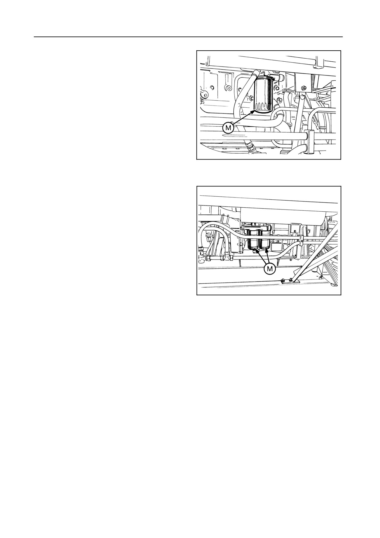
Filter change -- Figures 65 and 66
The oil filters should be changed every time the oil is
changed.
Access is gained through the grain tank.
Proceed as follows:
1. Remove the ‘‘spin-on” filter(s) M.
52732
2. Fill up the new filters with oil and apply a film of oil
65
to the seal ring.
3. Screw on the filters by hand. Tighten firmly but DO
NOT USE TOOLS!
4. Renew the engine oil. Refer to the paragraph
headed ‘‘Recommended oil and filter change in-
tervals’’.
5. Start the engine and check the oil filters for leaks.
55013
66
TX68-68PLUS
CHAINS, THREADED RODS AND PIVOT POINTS
Chains
Lubricate the following chains DAILY AND IMMEDI-
ATELY AFTER WORK.
In this way the oil will penetrate into the chains and
provide excellent protection and lubrication. Use a
special (biodegradable) chain oil or an SAE 90 gear
oil. (Belt and chain charts are included in Section 5 -
ADJUSTMENTS AND MAINTENANCE).
S Returns auger drive
S Grain elevator drive
S Unloading auger drive
3-16
SECTION 3
Threaded rods
Lubricate the following rods every 200 operating
hours:
S Drum variator
S Fan variator
Lubricate all threaded rods of the spring-loaded idlers
and all other threaded rods where adjustments are
carried out at least once a season.
Pivot points
It is recommended to oil all pivot points (including
guard pivot points) which may become stiff from cor-
rosion or dirt every 200 operating hours.
BRAKE FLUID -- Figure 67
Fluid level
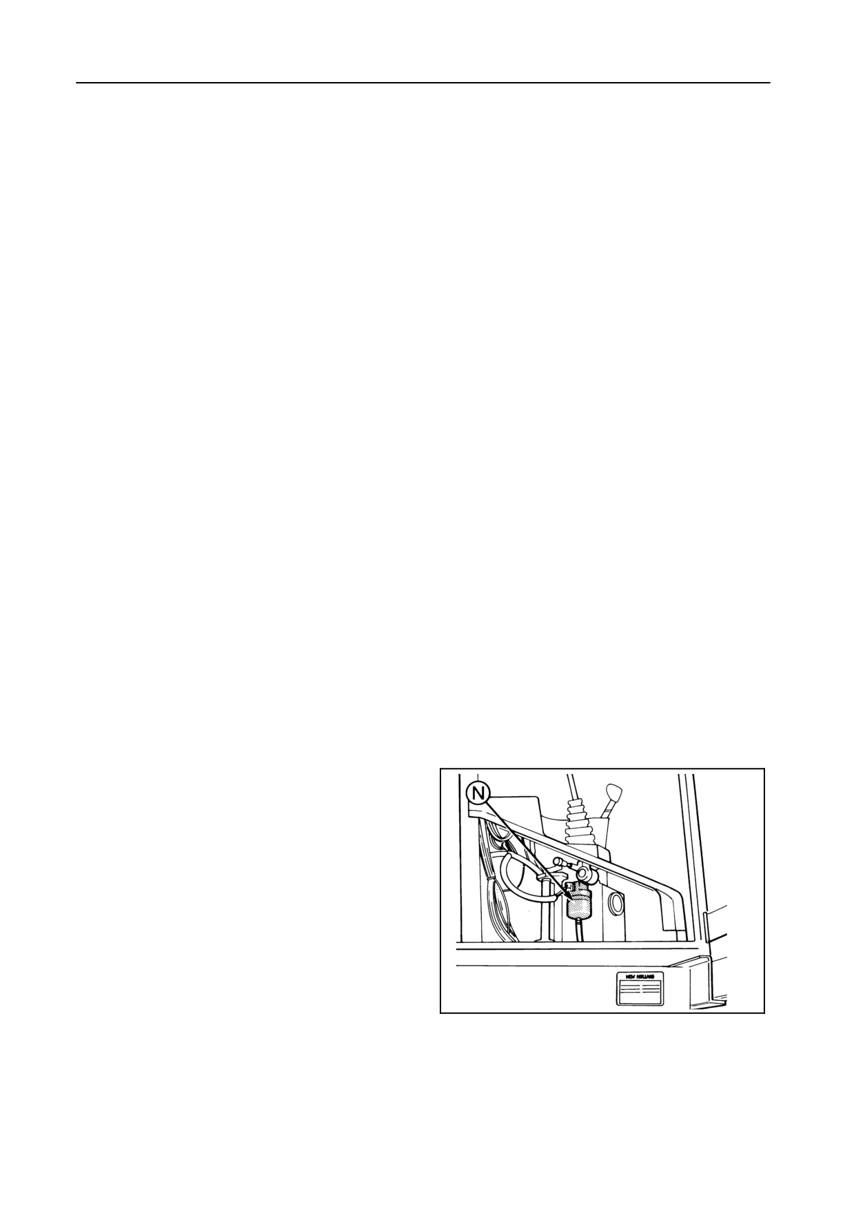
The fluid level is electrically controlled.
The warning light (Section 2 , Fig. 10 - item 31) will illu-
minate whenever the fluid level is too low or the brake
linings are worn.
The reservoir is accessible from the outside of the cab
after opening the right-hand cab door.
42813
67
3-17
LUBRICATION
Fluid change
The brake fluid has to be changed every two years.
Contact your New Holland dealer to carry out this job.
Capacity
Reservoir N: 0.5 litre
Entire brake system : 2 litres
Fluid specification
Use AMBRA SYNTFLUID 4 brake fluid (ref. NH800A)
or brake fluid meeting the NHTSA 116-DOT4 or ISO
4925 specification.
CAUTION:
Brake fluid has a tendency to absorb
moisture and break down over time.
Therefore it should be replaced every
two years.
As brake fluid contains substances
which, when mixed with engine or
other oils, create problems for recy-
cling the oil, do not mix oils, but collect
separately.
In the event of leakage or malfunction
of the brake fluid system, contact your
local dealer.
3-18
SECTION 3
HYDRAULIC SYSTEM -- Figures 68 to 71
Oil reservoir
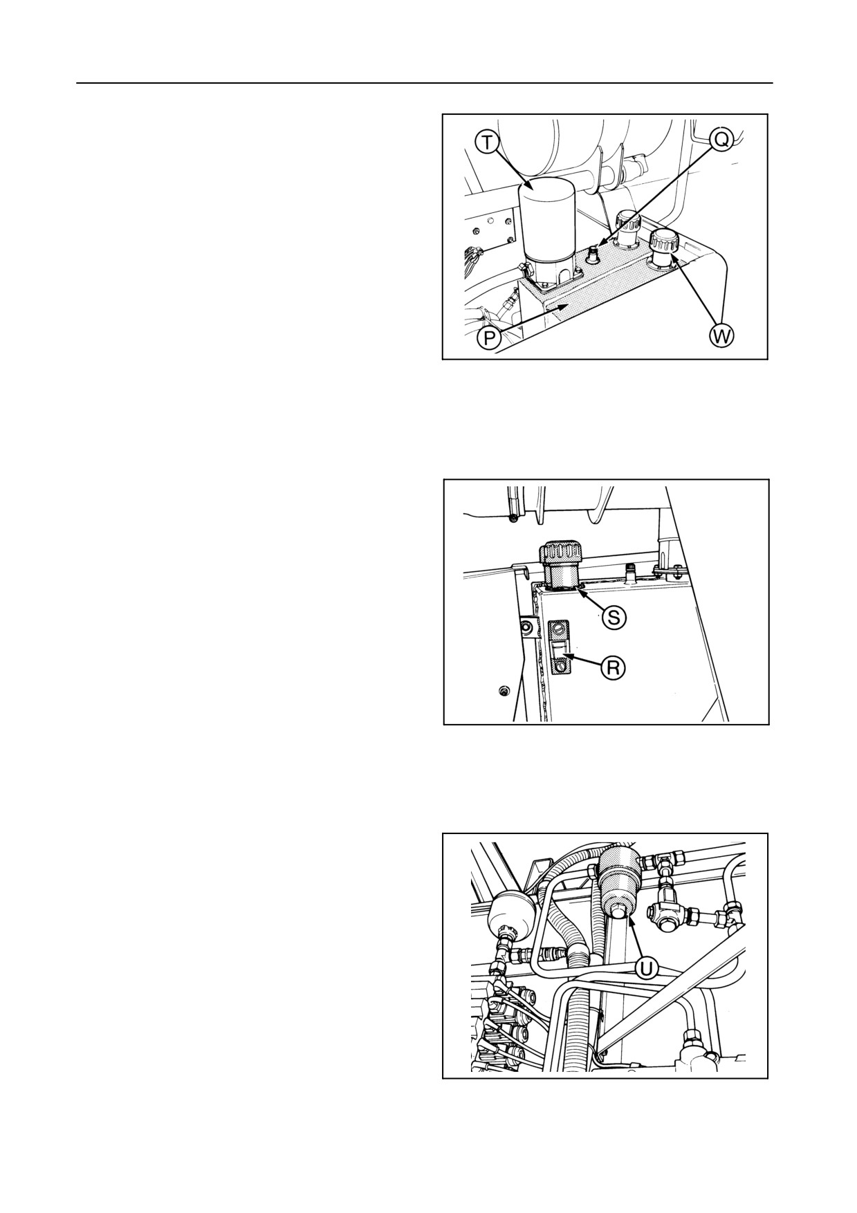
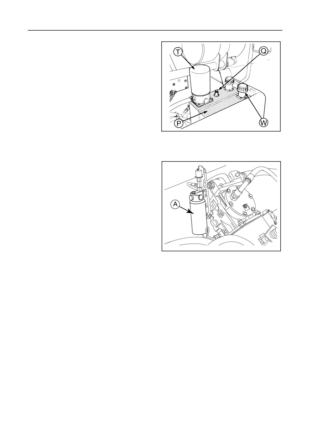
A single oil reservoir is fitted for the hydraulic and hy-
drostatic systems. A baffle in the tank separates the
hydraulic and hydrostatic oils. The left-hand side P
contains the oil for the hydrostatic system. The right-
hand side Q contains the oil for the hydraulic system.
42806
Oil level
68
ENSURE THAT ALL HYDRAULIC CYLINDERS ARE
RETRACTED BEFORE CHECKING THE OIL
LEVEL.
The oil level should be checked daily on the level
gauge R and should be kept between the marks.
If necessary, add oil through the filler opening S.
Oil and oil filter change
S After the first 100 operating hours
S Thereafter, every 400 operating hours, or an-
nually.
IMPORTANT:
42805
The return filter T (low pressure filter) and the
69
high pressure filter U should be changed at
each oil change.
To change the oil and both filters, proceed as follows:
1. Clean the reservoir filler cap and surrounding
area (with compressed air, if possible).
2. Drain the oil from the reservoir at hose V.
3. Remove the ‘‘spin-on” return filter T with a filter
wrench.
4. Apply a film of oil to the gasket of the new return
filter.
5. Screw on the new return filter by hand. Tighten
42812
firmly but DO NOT USE TOOLS.
70
3-19
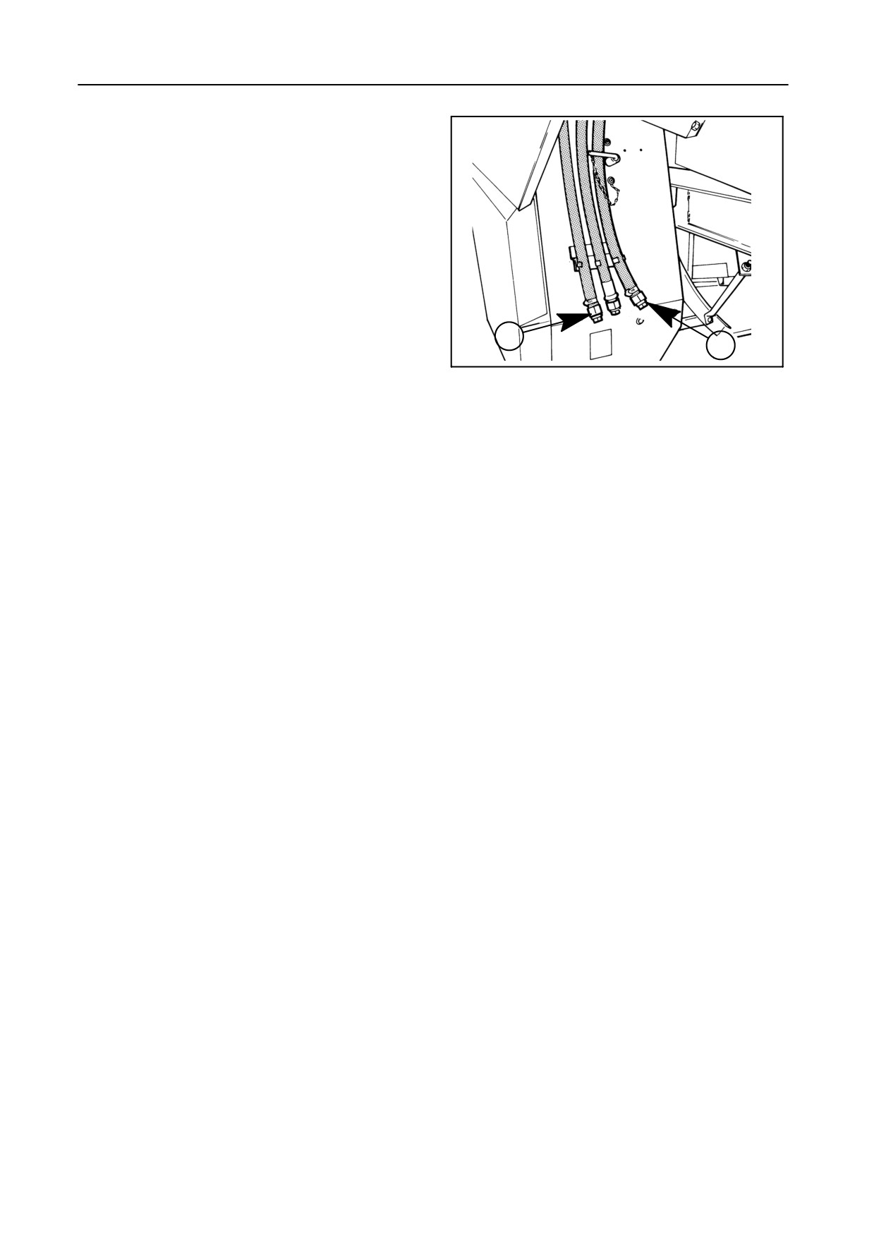
LUBRICATION
6. Remove the high pressure filter bowl U (spanner
width: 32 mm).
7. Change the high pressure filter element.
8. Tighten the bowl with a spanner to a torque of 80
Nm.
9. Refill the reservoir with hydraulic oil.
Z
V
42809
10. Check the oil level on the level gauge R.
71
IMPORTANT:
Always clean the reservoir filler cap and the
surrounding area before removing the cap to
top up or replace the oil.
Oil capacity
Reservoir: 20 litres
Entire system capacity: 32 litres
Oil specification
Use AMBRA HYDROSYSTEM 46 (ref. NH646), AM-
BRA HYDROSYSTEM 46 BIO-S (ref. NH646BS),
AMBRA HYDROSYSTEM 46 BIO-V (ref. NH 646 BV)
hydraulic oil or an oil meeting the following specifica-
tion:
S DIN 51524 Part 2 or ISO VG 46
S Viscosity grade: HV 46
The hydraulic system is factory-filled with AMBRA
HYDROSYSTEM 46 hydraulic oil (ref. NH646). This
is a hydraulic oil with a high viscosity index, which
means that the oil remains fluid at low temperatures.
3-20
SECTION 3
HYDROSTATIC SYSTEM -- Figures 72 and 73
Oil level
The oil level should be checked daily on the oil dipstick
fitted on the cap W.
Keep the oil level between the marks on the oil dip-
stick.
42806
72
Oil and oil filter change
S After the first 100 operating hours
S Thereafter, every 400 operating hours, or an-
nually.
To change the oil and filter, proceed as follows:
1.
Thoroughly clean the surrounding area of the res-
ervoir and filter (with compressed air, if possible).
2.
Remove the filler cap/oil dipstick W.
3.
Drain the oil from the reservoir through hose Z.
4.
Remove filter A.
30838
5.
Apply a film of oil to the gasket and screw on the
73
new filter by hand.
6.
Fill the reservoir up to the maximum oil level on
the oil dipstick.
7.
Start the engine. The audible warning in the cab
must cease functioning as soon as the engine
starts.Thelowhydrostaticchargepressurewarn-
ing light (Section 2, Fig. 10 - item 29) must extin-
guish as soon as the engine starts. If not, contact
your dealer for assistance.
Run the engine at idle speed for five minutes and
move the ground speed control lever slowly for-
ward and rearward with the gearshift lever in neu-
tral and the rear-wheel drive [if installed] disen-
gaged.
8.
Check the oil level on the level gauge and, if nec-
essary, add oil up to the maximum mark on the oil
dipstick.
3-21
LUBRICATION
Oil capacity
Reservoir: 18 litres
Entire system capacity: + 32 litres
Oil specification
Use AMBRA HYDROSYSTEM 46 (ref. NH646), AM-
BRA HYDROSYSTEM 46 BIO-S (ref. NH646BS),
AMBRA HYDROSYSTEM 46 BIO-V (ref. NH646BV)
hydraulic oil or an oil meeting the following specifica-
tion:
S DIN 51524 Part 2 or ISO VG 46
S Viscosity grade: HV 46
The hydrostatic system is factory-filled with AMBRA
HYDROSYSTEM 46 hydraulic oil (ref. NH 646). This
is a hydraulic oil with a high viscosity index, which
means that the oil remains fluid at low temperatures.
ATTENTION:
Oil quality and cleanliness is of utmost
importance for the reliability and life of the
hydrostatic system. Deviation of the pre-
scribed oil specification may lead to se-
vere damage and void the warranty!
3-22
SECTION
3
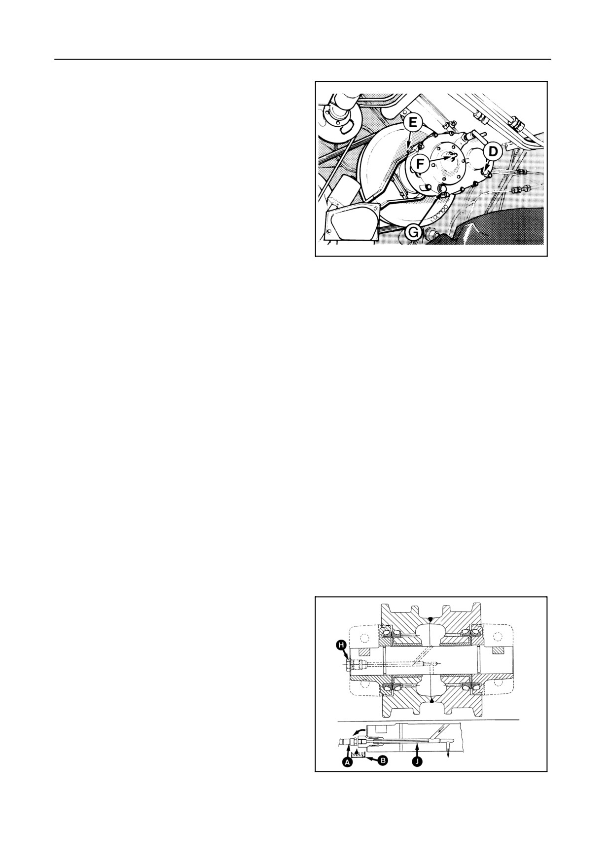
DRUM SPEED REDUCER [if installed] -- Figure 74
Oil level
Check the oil level daily through sight glass D.
If necessary, add oil through the filler plug E. Plug F is
the breather.
Oil change
S After the first 50 operating hours
21180
S Thereafter, every 200 hours of operation.
74
Drain the oil through drain plug G and fill the gearbox
with 1 litre of oil.
Gearbox capacity
Approximately 0.15 kg of grease and 0.8 litre of oil.
Lubricant specification
Use AMBRA GR9 (ref. NH710A) or AMBRA GR75MD
(ref. NH720A) multipurpose grease, or a grease
meeting the NLGI 2 specification.
Use AMBRA HYPOIDE 90 gear oil (ref. NH520A) or
an oil meeting the following specification:
S API GL5 or MIL-L 2105D
S Viscosity grade: SAE 80W90
TRACKS [if installed] -- Figure 75
Oil level
With the combine standing on a level surface, the oil
should reach level plug H.
Oil change
S Every 200 operating hours, or
S Annually (after the season), whichever comes
50101
first.
75
3-23
LUBRICATION
Oil capacity
Track roller: 0.35 litre
Guide wheel: 0.35 litre
Oil specification
Use AMBRA UNIVERSAL oil (ref. NH024C) or an oil
meeting the following specification:⋅
S API CE, MIL-L 2104E, MIL-L 2105, CCMC D4
or API GL4
S Viscosity grade: SAE 10W30
The track roller and guide wheels are factory-filled
with AMBRA UNIVERSAL (ref. NH024C) oil.
Oil change
To change the oil, proceed as follows:
1. Remove the hexagonal plug H from the track rol-
ler/guide wheel and screw the special lubrication
pipeJ[deliveredwiththetracks]intothehole.The
oil pump A should then be screwed onto the other
end of the pipe.
2. Place a tray B underneath the pipe to collect the
waste oil.
3. Pump oil into the track roller/guide wheel until the
new oil starts running out of the pipe (rinsing prin-
ciple).
4. Unscrew the oil pump, remove oil pipe J and rein-
stall hexagonal plug H .
5. Repeat the same procedure with the other track
rollers/guide wheels.
3-24

SECTION 3
LUBRICATION SCHEDULE
Item
Servicing
Amount/
NEW HOLLAND
NEW HOLLAND
Lubricant
International
interval
unit
brand name
specification
grade
specification
(litres)
Grease
10 h
--
AMBRA GR9
NH710A
NLGI 2
--
nipples
50 h
--
or
or
100 h
--
AMBRA
NH720A
NLGI 2
--
GR75MD
Traction
Change
15
AMBRA
NH520A
SAE
API GL5,
gearbox
- after first 100h
HYPOIDE 90
80W90
MIL-L 2105D
- after first 200h
- every 400h or
annually
Final
Change
TX62-63-
AMBRA
NH520A
SAE
API GL5,
drive
- after first 100h
64PLUS-66:
HYPOIDE 90
80W90
MIL-L 2105D
gearboxes
- after first 200h
5 litres
- every 400h or
annually
TX65PLUS-67
-68-68PLUS:
6 litres
Engine
Check daily
TX62 to 67:
AMBRA
NH330B
SAE
API CD/SF
(sump without
Change
21-23 litres
PREMIUM
15W40
MIL-L 2104D
filter)
MULTIGRADE
- after first 50h
TX68-68PLUS:
- every 200h, or
15-20 litres
AMBRA
NH330G
SAE
API CF-4/SG,
- every 300h
SUPER GOLD
15W40
CCMC D4,
MULTIGRADE
MIL-L 2104E
Chains
Daily
--
AMBRA
NH520A
SAE
API GL5,
Threaded rods
200h
HYPOIDE 90
80W90
MIL-L 2105D
Pivot points
200h
Brake system
Change
0.5
AMBRA
NH800A
--
NHTSA
every 2 years
(reservoir)
SYNTFLUID 4
116-DOT 4,
2
(system)
ISO 4925
Hydraulic
Check daily
20
AMBRA HYDRO-
NH646
HV 46
DIN 51524
system
Change
SYSTEM 46
NH646BS
Part 2,
(oil + filters)
- after first 100h
NH646BV
ISO VG 46
- every 400h or
annually
Hydrostatic
Check daily
18
AMBRA HYDRO-
NH646
HV 46
DIN 51524
system
Change
SYSTEM 46
NH646BS
Part 2,
(oil + filters)
- after first 100h
NH646BV
ISO VG 46
- every 400h or
annually
Tracks
Service
0.35/roller
AMBRA
NH024C
SAE
API CE,
(track rollers
every 200h or
0.35/wheel
UNIVERSAL
10W-30
MIL-L 2104E,
and guide
annually
MIL-L 2105,
wheels)
CCMC D4,
API GL4
Drum
Change
0.15
AMBRA GR9
NH710A
NLGI 2
--
speed
- after first 50h
or
or
reducer
- every 200h
AMBRA
NH720A
NLGI 2
--
GR75MD
0.8
AMBRA
NH520A
SAE
API GL5,
HYPOIDE 90
80W90
MIL-L 2105D
Antifreeze
Change
47.5 %
AGRIFLU
NH900A
--
--
every 2 years
3-25
SECTION 4
FIELD OPERATION
GENERAL INFORMATION
4.
Adjust the following according to the type of crop
being harvested:
WARNING:
Some functional parts of the combine
S Header
cannot have safety guards, therefore:
S Concave clearance and threshing drum speed
Ensure everyone is clear of the combine
before starting the engine.
S Sieve openings and cleaning fan speed
Be careful:
5.
Ensure the battery key is in the ON position.
S When engaging the grain header, for
the rotating reel and moving knife
6.
Start the engine and let it warm up for one minute
at idle speed.
When engaging the maize header, for
the intake feed chains
7.
Engage the threshing mechanism.
S When raising and lowering the header
and the straw elevator
IMPORTANT:
S Models TX62-63
S When engaging the straw chopper.
To increase belt live, always engage the
threshing mechanism with the engine run-
ning at idle speed.
S ModelsTX64PLUS-65PLUS-66-67-68-68PLUS
To increase belt live, an incorporated
electronic
belt
protection
system
automatically brings the engine to idle
BEFORE STARTING OPERATION
speed when engaging the threshing
mechanism or the straw chopper drive.
1. Check the wheel nut torques (refer to Section 9 -
SPECIFICATION).
8.
Press the throttle switch until maximum speed is
2. Check the engine coolant level, engine oil level,
reached.
hydraulic oil level, hydrostatic oil level and fuel
9.
Adjust the cleaning fan and drum rpm according to
level.
the type of crop being harvested. The cleaning fan
3. Check all belt and chain tensions (refer to Section
and drum rpm can be observed on the InfoView
5 - ADJUSTMENTS AND MAINTENANCE).
monitor.
4-1
FIELD OPERATION
HEADER
Refer to the separate operator’s manual for the
header type attached to your combine.
HEADER HEIGHT CONTROLS -- Figures 1 and 2
When changing the header, perform the header
height control (refer to paragraph ‘‘Header height con-
trol calibrations’’ and ‘‘InfoView Monitor’’, subheading
‘‘7. Calibrations’’).
IMPORTANT:
To enter an automatic header height control
mode (compensation, autofloat or stubble
13
height), proceed as follows:
1. Engage the threshing mechanism
2. Select a mode, and
3. Give a pulse on the automatic header
height control switch 20.
43073
The green autodiagnostic indicator illuminates
1
if the header is working in an automatic header
height control mode with the preselected stub-
ble height (autofloat and stubble height) or
preselected pressure (compensation).
To switch from one automatic mode to another,
select the required operation mode with selec-
tor switch 17 and give a pulse on automatic
header height control switch 20 to enter the se-
19
lected mode.
20
22
Manually operating header height control
switch 13 always has priority of the selected
automatic header height control mode (com-
pensation, autofloat or stubble height) and will
17
also disengage this automatic mode. Re-enter
42972
the automatic mode by giving a pulse on switch
2
20.
4-2
SECTION 4
NOTE
Figure 3:
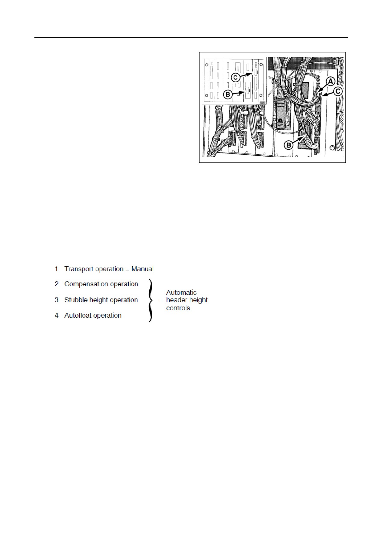
When using a grain or maize header fitted with
autofloat sensors, plug A must be plugged into
socket B.
When using a flex header, plug A must be
plugged into socket C, as shown.
NOTE:
S The header calibration must be performed
when changing the header.
S To operate a flex header, the autofloat op-
51714
eration mode must be selected.
3
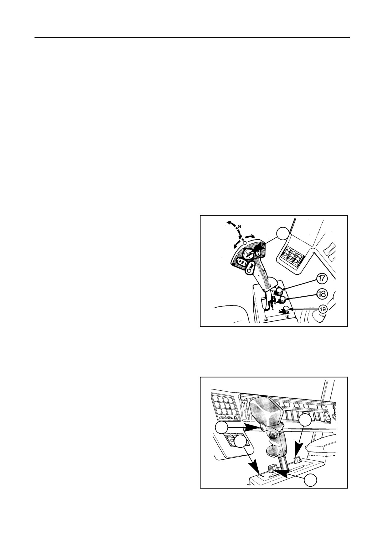
OPERATION MODES
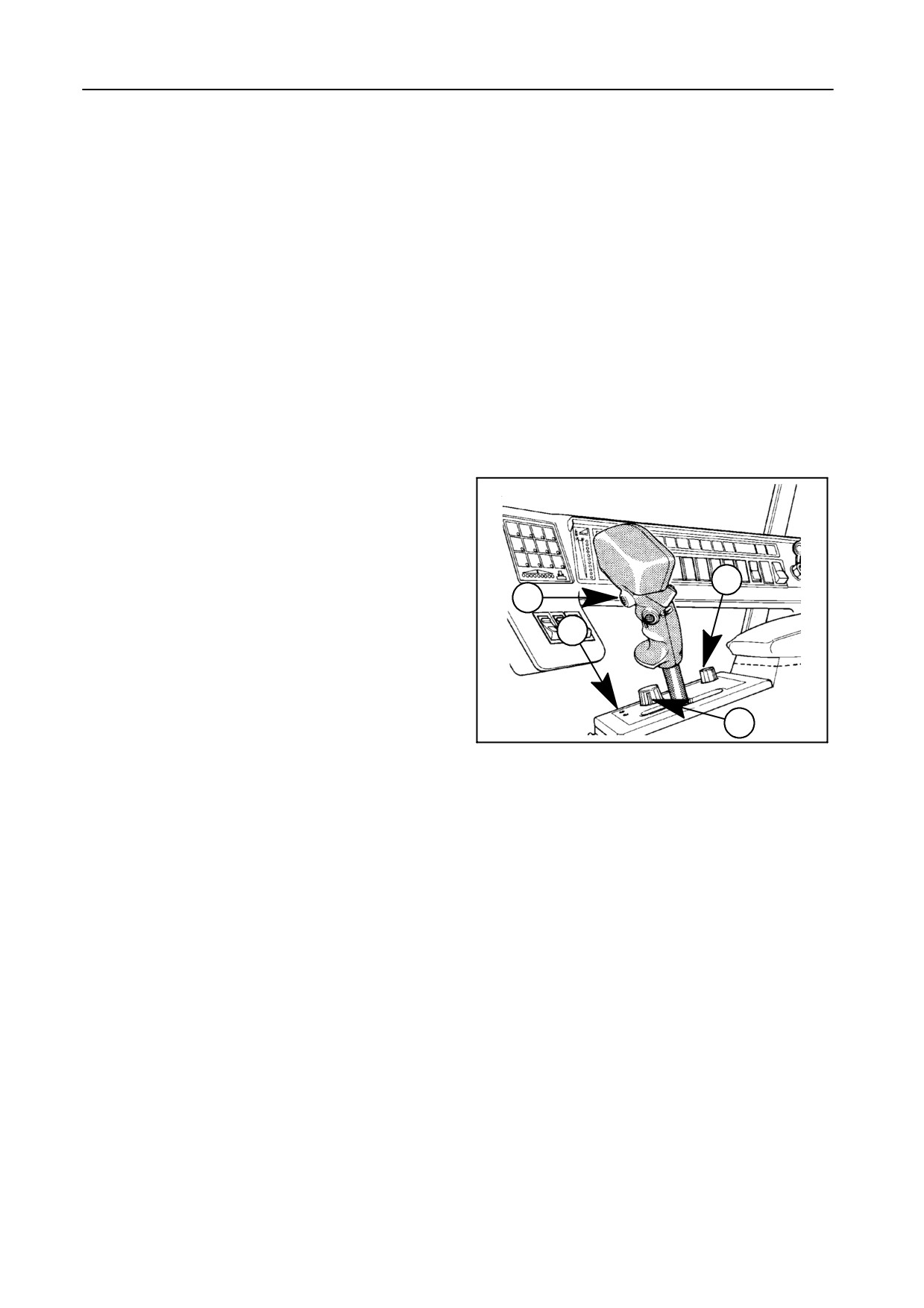
With the header control selector switch 17 four differ-
ent operation modes are possible:
Transport operation -- Figure 1
ALWAYS use this mode for road transport, attaching
and detaching the header.
When the threshing mechanism is disengaged, this
mode is automatically selected.
Turn selector switch 17 fully counterclockwise and
raise the header by pushing on the upper part of
rocker switch 13 (2-speed function).
Lower the header by pushing on the lower part of
rocker switch 13 (2-speed function).
Tilt down the left-hand side of the header by pushing
on the left part of button 13.
Tilt down the right-hand side of the header by pushing
on the right part of button 13.
4-3
FIELD OPERATION
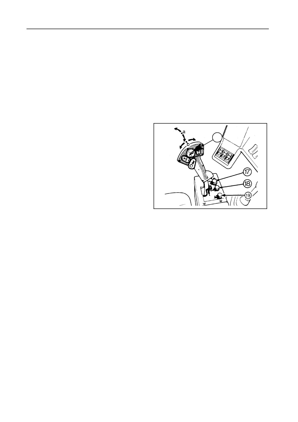
Compensation operation -- Figures 4 and 5
Use this mode when harvesting peas and/or laid
crops. In this operation mode the header slides over
the ground with a preselected pressure.
In this mode it is also possible to obtain an automatic
lateral flotation if autofloat sensors are installed.
The sensors should be connected to the combine and
the outer header skids should be in pivoting position
(i.e. hanging loose).
Turn selector switch 17 to the P-symbol.
Give a pulse on the automatic header height control
switch 20 and the header will automatically lower to
the preselected pressure when the threshing
mechanism is engaged.
After pressing the automatic header height control
switch 20, the green autodiagnostic indicator 22 will
start blinking and remain so to show the
19
compensation operation is engaged.
20
22
The preselected pressure can be adjusted during har-
vesting by means of the header compensation control
knob 19.
Turn counterclockwise (+) to increase the pressure of
17
42972
the header onto the soil.
4
Turn clockwise (--) to reduce the pressure of the head-
er onto the soil.
Operating the header height control rocker switch 13
[vertically] disengages the compensation system into
the transport mode [priority]. The green autodiagnos-
tic indicator 22 will extinguish.
A pulse on the automatic header height control switch
20 will bring the header back to the compensation op-
eration.
When setting the compensation, it can maximum be
set at 108% of the header weight, which means that
the header will start to raise.
When setting this height, the header will not always
follow the ground contours when passing an obstacle.
In this case, it has to be set slightly heavier.
4-4
SECTION 4
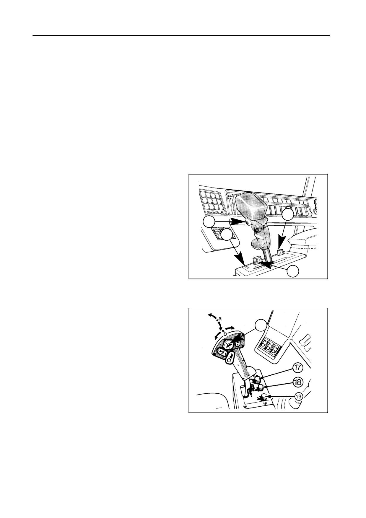
Stubble height operation -- Figures 4 and 5
The header operates at a preselected stubble height.
Use this mode when harvesting standing crops or
when operating in stony conditions and at higher
stubble height.
Inthismodethe autofloat sensors [if installed] aredis-
engaged and the header can only be tilted manually
with rocker switch 13.
An automatic compensation is built in when touch-
ing the ground. After the header clears the ground, it
automatically returns to the preset stubble height.
13
Turn selector switch 17 to the S-symbol.
Give a pulse on the automatic header height switch 20
and the header will automatically lower to the
preselected stubble height when the threshing
mechanism is engaged.
The green autodiagnostic indicator 22 illuminates to
show that the header is operating at the preselected
stubble height.
43073
5
The preselected stubble height can be adjusted dur-
ing harvesting by means of the header stubble height
control knob 18.
Turn knob
18
clockwise
(+) to increase the
preselected stubble height.
Turn knob 18 counterclockwise (--) to reduce the
preselected stubble height.
Operating the header height control rocker switch 13
vertically lowers or lifts the header into the transport
mode [priority]. The green autodiagnostic indicator 22
extinguishes. To reenter the stubble height mode,
give a pulse on the automatic engagement switch 20.
4-5
FIELD OPERATION
Autofloat operation [if autofloat sensors are in-
stalled] -- Figures 6 and 7
The header will follow the field contours at a
preselected stubble height. Use this mode when a
short stubble is required.
An automatic compensation is built in when touch-
ing the ground. Once the header clears the ground, it
automatically returns to the preset stubble height.
Turn selector switch 17 fully clockwise. Give a pulse
on the automatic header height control switch 20 and
the header will automatically lower to the preselected
stubble height when the threshing mechanism is en-
gaged.
19
The green autodiagnostic indicator 22 illuminates to
20
show that the header is operating at the preselected
stubble height.
22
The preselected stubble height can be adjusted dur-
ing harvesting by means of the header stubble height
17
42972
control knob 18.
6
Turn knob
18
clockwise
(+) to increase the
preselected stubble height.
Turn knob 18 counterclockwise (--) to reduce the
preselected stubble height.
13
Operating the header height control rocker switch 13
vertically or sideways (lateral float) disengages the
autofloat system completely into the transport mode.
The green autodiagnostic indicator 22 extinguishes.
To return to the preselected stubble height and incli-
nation, give a pulse on the automatic header height
43073
control switch 20.
7
4-6
SECTION 4
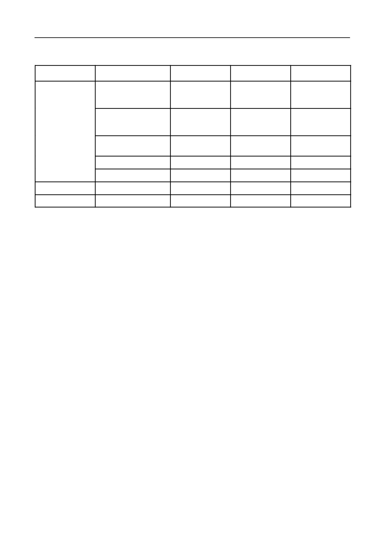
SYSTEM APPLICATION CHART
HEADER
CONDITIONS
COMPENSATION
STUBBLE
AUTOFLOAT
Ground contact,
Badly laid crops,
X
Peas, Beans, etc.
Standing crops
Undersown conditions
X
(X)
Green undergrowth
Grain header
Standing crops
X
X
Good conditions
Rape seed (Direct cut)
X
Rice crop
X
Maize header
All
X
X
Flex header
All
X
FLEX HEADER OPERATION (Italy only)
IMPORTANT:
For a correct flex header operation the stubble
height control knob 18 has to be set in ONE
SPECIFIC POSITION!
Proceed as follows -- Figures 6 and 7:
1. Manually lower the header to the ground
(with
header height control switch 13).
2. Engage the threshing mechanism.
3. Turn selector switch 17 fully clockwise into the Au-
tofloat position.
4. Turn stubble height control knob 18 fully counter-
clockwise.
5. Give a pulse on the automatic header height con-
trol switch 20. The header will raise slowly.
6. Turn stubble height control knob 18 slowly clock-
wise until the header stops raising.
7. Turn stubble height control knob 18 slowly further
clockwise until the header lowers into the flex
header operation zone indicated on the header.
Maintain the position of knob 18!
4-7
FIELD OPERATION
HEADER HEIGHT CONTROL CALIBRATIONS
Purpose
To obtain a correct functioning of the automatic head-
er height control modes (compensation / stubble
height / autofloat, if installed), three calibrations have
to be performed:
S Calibration of the ground level
S Calibration of the maximum cylinder pressure
S Calibration of the ground level through autofloat
sensors (if the autofloat system is installed)
These calibrations have to be carried out:
S At the first start-off (i.e. at the factory)
S When changing the wheel size or the header
S When adding one header lift cylinder
S When system components were replaced
To calibrate the automatic system, the appropriate
header has to be attached and the combine has to be
placed on a level surface.
Perform the two or three calibrations in sequence, ex-
cept when operating a flex header: the calibration of
the ground level through autofloat has to be made
during the InfoView calibration (refer to paragraph
headed ‘‘InfoView Monitor’’, subheading ‘‘7. Calibra-
tions’’, further in this Section).
4-8
SECTION 4
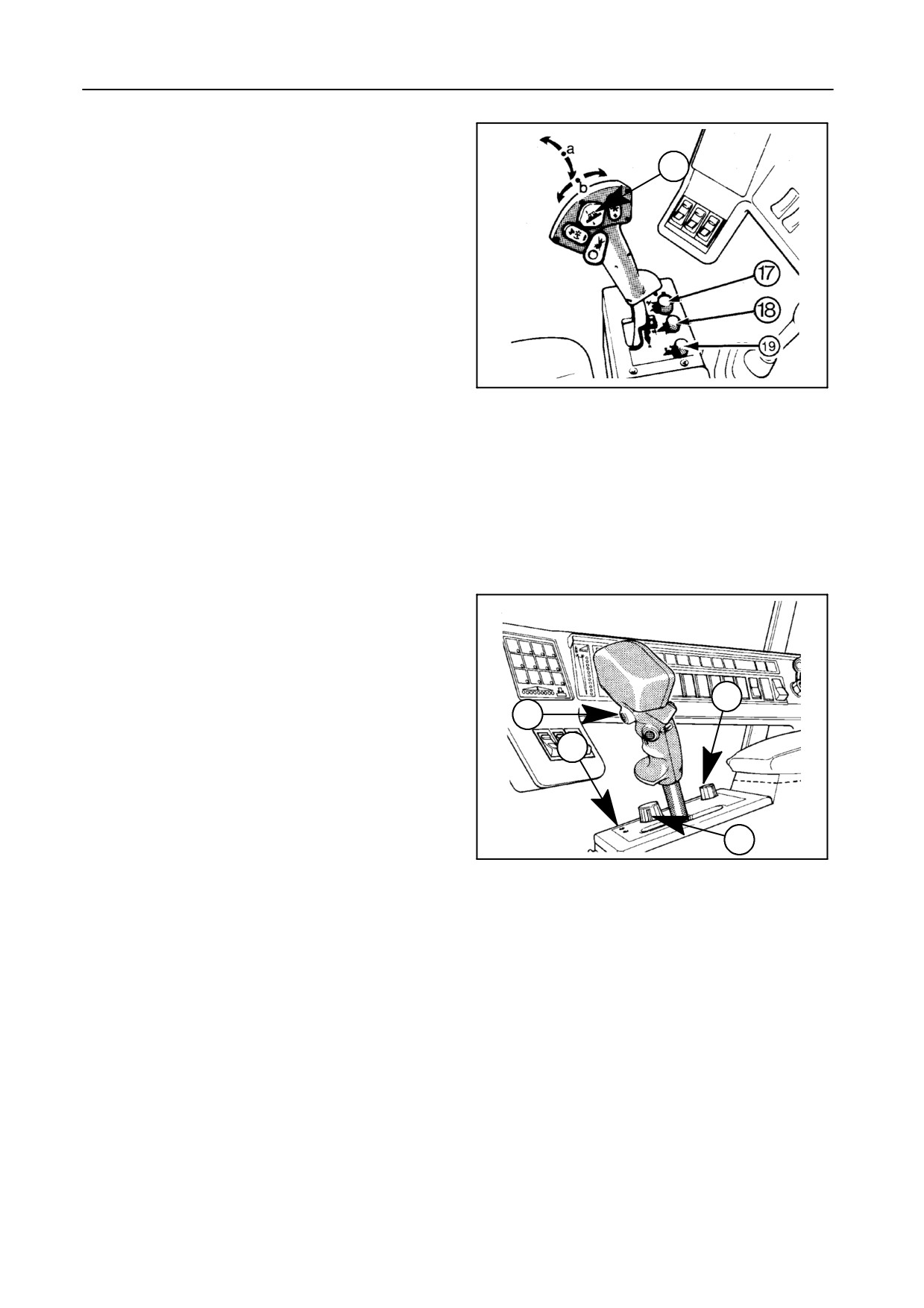
Calibration of the ground level -- Figures 8 and 9
13
1. Start the engine.
2. Select the transport position with selector switch
17.
3. Lower and lift the header with the header height
control rocker switch 13 at least once.
4. Lower the header to ground level by simulta-
neously pressing header height control rocker
43073
swith 13 and automatic header height control
8
switch 20. Hold both switches until the green
autodiagnostic indicator 22 has blinked 5 times.
Calibration of the maximum cylinder pressure --
Figures 8 and 9
1.
Start the engine.
19
20
2.
Select the transport position with selector switch
17.
22
NOTE:
Steps 1 and 2 need not be carried out if this cal-
ibration is performed immediately after the
17
ground level calibration.
42972
9
3.
Lower and lift the header with the header height
control rocker switch 13 at least once.
4.
Lower the header just above ground level (the
header must not touch the ground).
NOTE:
The lowering of the header must be the last op-
eration.
5.
Push and hold the automatic header height switch
20 for 10 seconds without touching other switches
until the green autodiagnostic indicator 22 has
blinked 8 times.
4-9
FIELD OPERATION
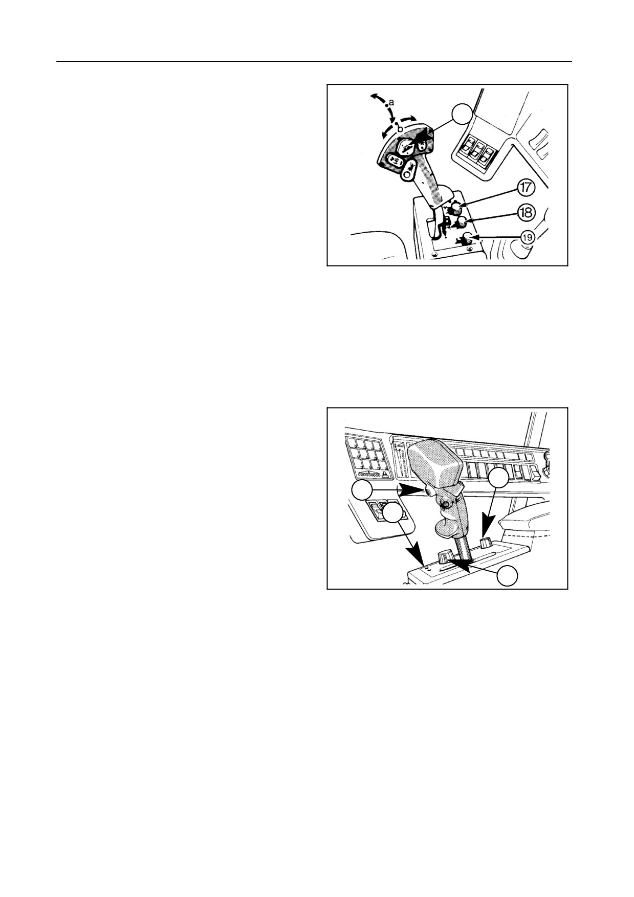
Calibration of the ground level through autofloat
sensors -- Figures 10 and 11
13
NOTE:
S Ensure the autofloat sensors are con-
nected.
S If a flex header is installed, perform this
calibration only during calibration of the In-
foView Monitor. Refer to paragraph headed
‘‘InfoView monitor’’, subheading 1.6, fur-
ther in this Section.
43073
10
1.
Loosen the plastic fixation strips holding the outer
header skids and ensure the skids are in pivoting
postion (i.e. hanging loose) [not applicable for flex
header].
2.
Start the engine.
3.
Select the transport position with selector switch
17.
4.
Lower and lift the header with the header height
control rocker switch 13 at least once.
19
5.
Lower the header onto the ground with the header
20
height control rocker switch 13 and ensure the
22
header rests flat onto the ground. If not, adjust the
inclination with rocker switch 13.
6.
Check if the autofloat sensors are operating (a
17
buzzing noise is audible at the sensors) [not appli-
42972
cable for flex header].
11
7.
Push the automatic header height switch 20 and
simultaneously lift the header slowly (1st speed)
with header height control rocker switch 13.
Hold both switches (even with the header in the
highest position) until the green autodiagnostic in-
dicator 22 has blinked 10 times.
8.
Secure the plastic fixation strips of the header
skids [not applicable for flex header].
4-10
SECTION 4
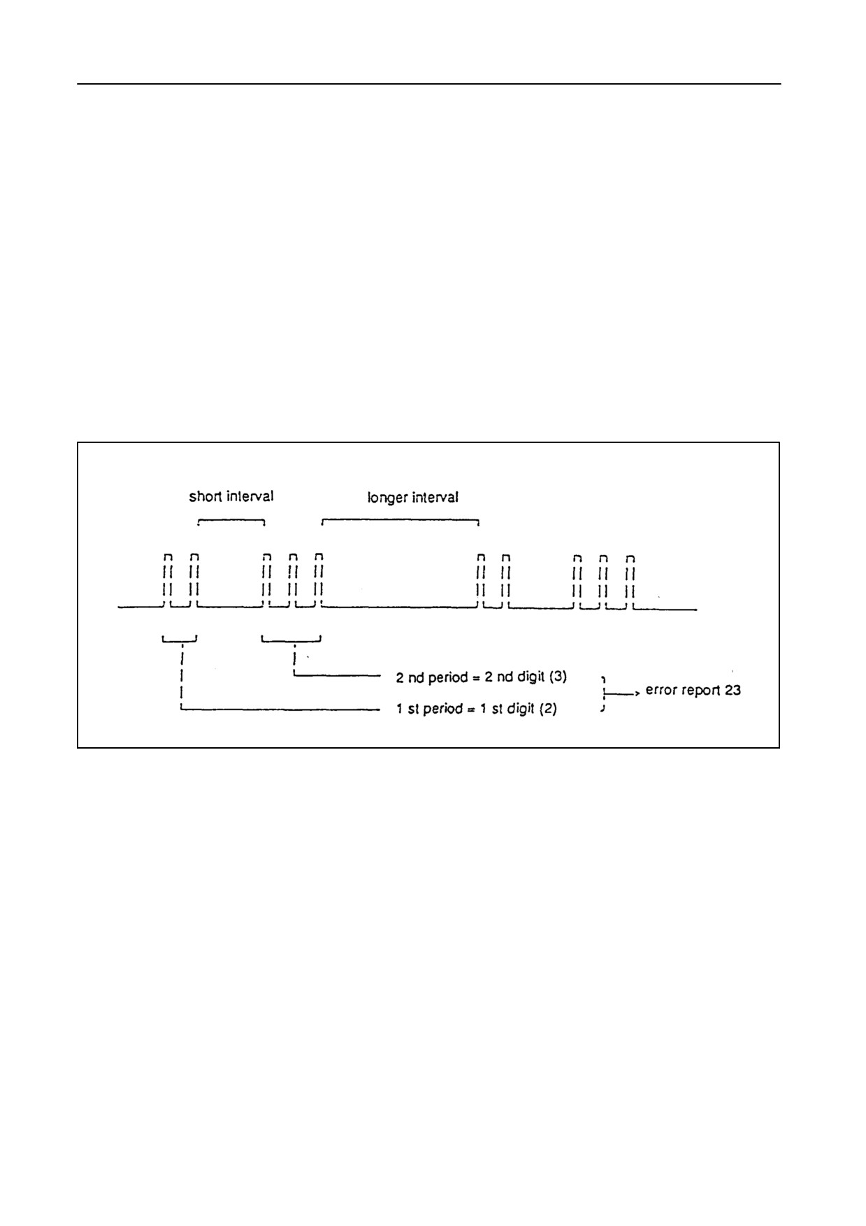
AUTODIAGNOSTICS -- Figure 12
The blinking sequence of the red autodiagnostic con-
trol light 22 identifies an error report.
The blinking sequence always consists of two periods
separated by a short interval. Then, after a longer in-
terval, the blinking sequence will repeat again.
The first period indicates the first digit of the error re-
port, the second period indicates the second digit.
Example
Error report 23
52002
12
4-11

FIELD OPERATION
ERROR REPORTS
Error ref.
Description
11
Failure or interruption of the solenoid to raise the header
12
Failure or interruption of the solenoid to lower the header
13
Short circuit in the stubble height and compensation control wiring loom
14
Interruption of the stubble height and compensation control wiring loom
15
Failure or interruption of header height control switch
16
No power supply to the control switches
17
Battery voltage higher than 18 V
18
Failure of selector switch 17
21
Failure of wiring loom to the header height sensor
22
Incorrect stubble height signal
23
Failure or interruption of the header cylinder pressure sensor
24
Incorrect pressure sensor signal
25
Failure of header height control switch
- section ‘‘Slow’’ or ‘‘Fast’’: OK
- section ‘‘Lower’’ or ‘‘Raise’’: NOT OK
31
No signal or incorrect signal from left-hand autofloat sensor [accessory]
32
No signal or incorrect signal from right-hand autofloat sensor [accessory]
33
Failure of automatic header height control switch 20 wiring loom
35
Battery voltage lower than 12 V
36
Failure of the hydraulic header height control valve (electrical control: OK)
4-12
SECTION 4
HEADER AND STRAW ELEVATOR REVERSING
SYSTEM
The combine is equipped with a system to reverse the
header reel (or the gathering chains, in case of a
maize header), the auger and the straw elevator
should a blockage occur.
If, during operation, a feed auger and/or a straw ele-
vator blockage occurs which makes the slip
clutch(es) slip, proceed as follows:
Model TX62
1.
Stop the combine immediately and disengage the
header engaging lever.
2.
Reverse the combine a couple of metres.
3.
Leave the throttle lever at maximum speed.
4.
Pull the spring-loaded lock A down and press the
reversing switch 45 (Fig.15).
IMPORTANT:
Hold the switch in the activated position.
This will activate the electric motor and thus re-
verse the straw elevator and header until the
blockage has been expelled.
5.
Release the reversing switch 45 (Fig.15).
6.
Lift-up the reel and engage the header engaging
lever.
7.
Move the crop slowly towards the auger with the
reel.
8.
Continue operation.
CAUTION:
If the blockage can not be removed by the
header reversing system, stop the engine
before attempting to unplug the header
manually.
4-13
FIELD OPERATION
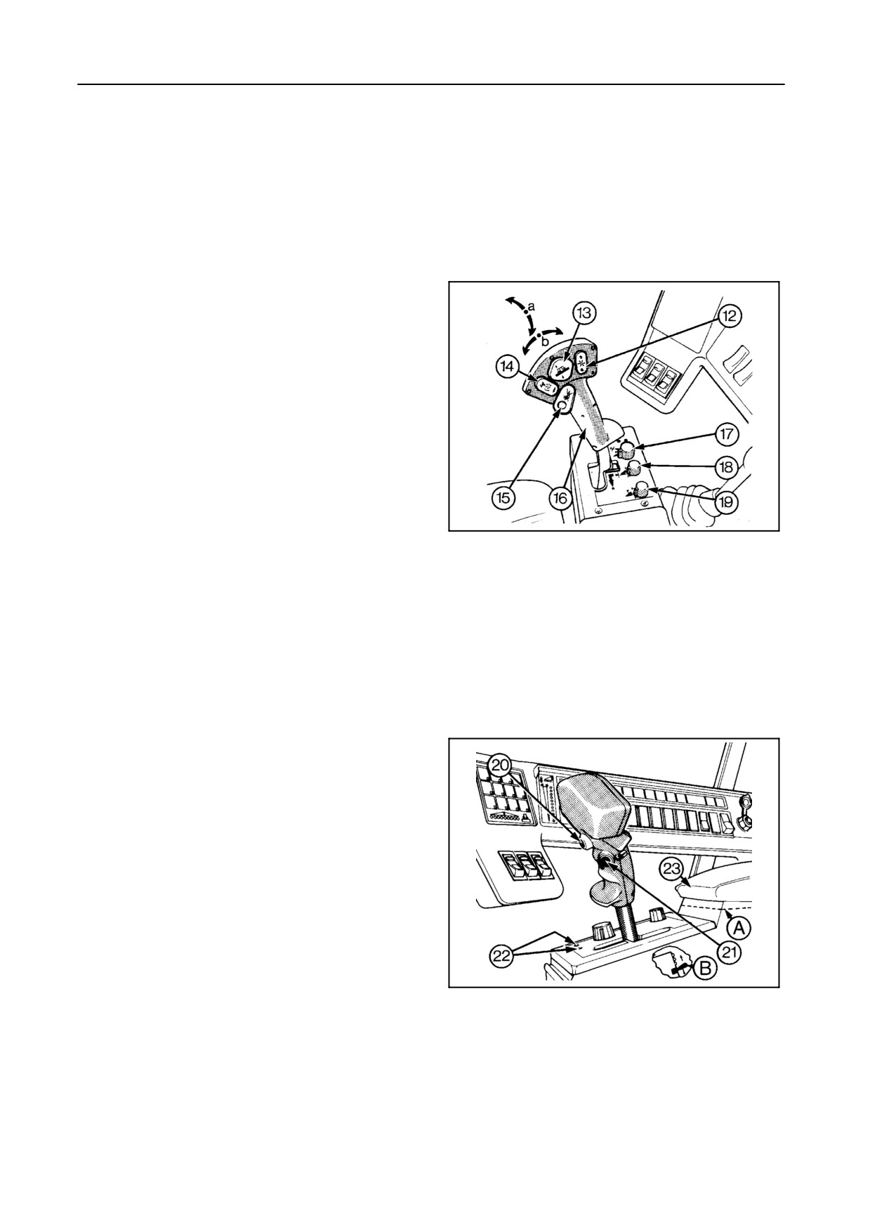
Models TX63-TX64PLUS-65PLUS-66-67-68-68PLUS --
Figures 13 and 14
1.
Stop the forward travel of the combine immedi-
ately and disengage the header drive with the
emergency stop switch 15.
2.
Reverse the combine a few metres.
3. a) Let the engine run at maximum speed and
switch OFF the header engagement switch 53
(Fig.15) and the unloading auger engagement
switch 55.
3. b) It is also possible to reverse the header, straw
elevator and threshing drum.
To do this, additionally switch OFF the threshing
mechanism engagement switch, lower the
42765
drum concave and switch ON the chopper en-
13
gagement switch.
4.
Push and hold the reversing switch 21 to re-
verse the rotation of header and straw elevator.
NOTE:
Pushing the lower part of the reel variator
switch 14 while holding the reversing switch
21 will rotate the header and straw elevator
forwards.
5. a)
When the blockage has been expelled, lift up
the reel and engage the header by switching
ON the header engagement switch 53 (Fig.15).
5. b)
In case reversing of the header and threshing
mechanism was needed, first switch OFF the
chopper before switching ON the threshing
mechanism, consequently the chopper (if re-
quired) and finally the header.
42759
14
IMPORTANT:
It is not possible to remove all blockages using
the reversing system. If necessary, remove the
blockage manually. Refer to the next para-
graph ‘‘Header and/or straw elevator blockage
-- manual clearing’’.
4-14
SECTION 4
CAUTION:
If the blockage cannot be removed by the
header reversing system, stop the engine
before attempting to unplug the header
manually.
6.
Grain headers only
Slowly move the crop with the reel to the feed
auger.
7.
Continue operation.
HEADER AND/OR STRAW ELEVATOR BLOCK-
AGE -- MANUAL CLEARING
CAUTION:
If the blockage cannot be removed by
means of the reversing system, disen-
gage all engagement systems, shut down
the engine and wait until all parts have
come to a standstill.
If the blockage is situated at the straw elevator upper
shaft, gain access through the straw elevator bottom
plate. Refer to the paragraph below.
If theblockageissituatedat thestraw elevatorbottom
shaft, it will be necessary to detach the header. Refer
to Section 2, paragraph headed‘‘Detaching thehead-
er from the combine’’.
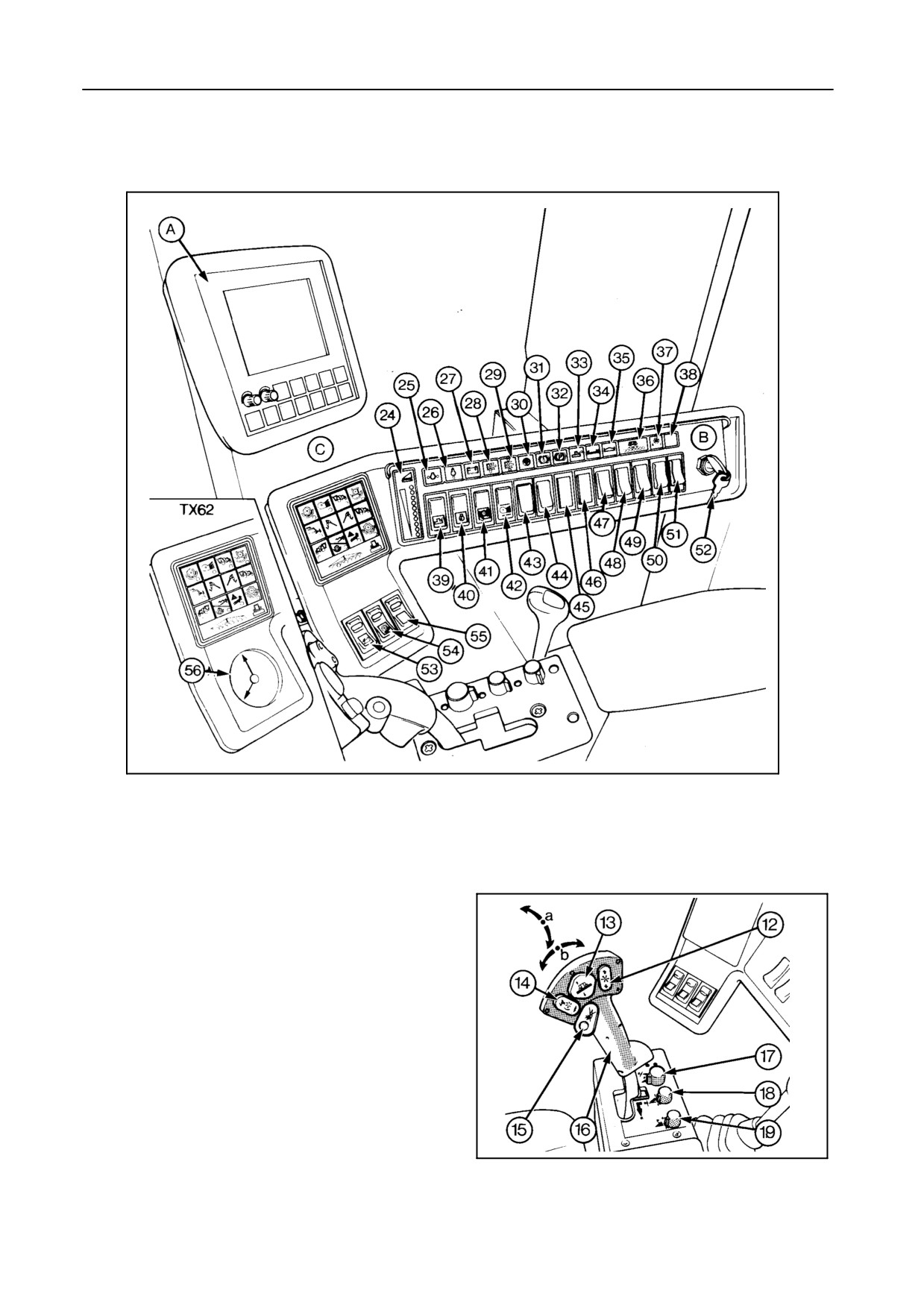
REEL TO GROUND SPEED SYNCHRONIZATION
With switch 43 (Fig.15) in the ON position, the reel
speed is synchronized to the ground speed. The ba-
sic ratio between the reel and the ground speed is
memorized in the central processing unit (part of the
fuse box). However, this ratio can be increased or de-
creased with the reel speed control switch
12
(Fig.13). The new ratio result will automatically be
memorized, replacing the existing ratio (still with
switch 43 in the ON position).
4-15
FIELD OPERATION
Reel synchro control -- Figures 15 and 16
42763
15
To obtain a proper reel synchro control, proceed as
follows:
1. Operate the combine in a section of the field that
best represents the overall crop.
2. Switch the reel synchro switch 43 in the ON posi-
tion, and adjust the reel speed with the reel varia-
tor switch 14 to match with the combine ground
speed.
42765
16
4-16
SECTION 4
NOTE:
S While activating the reel synchro by switch-
ing on the reel synchro switch 43, disregard
the fact that the reel speed increases to its
maximum speed or decreases to its mini-
mum speed.
This happens to a previous reel synchro
setting.
Adjust the reel speed with the reel variator
switch 14.
S As the electronic reel speed range is larger
than the mechanical reel speed, it may
take some seconds before the reel speed
reacts to the reel variator switch (with the
reel synchro ON).
3. Releasing the reel variator switch 14 will automati-
cally introduce the new relationship between the
reel speed and the combine ground speed in the
electronic system.
4. If you now change the combine ground speed, the
reel speed will be related automatically.
NOTE:
S If you now notice that the reel speed in-
creases or decreases too fast in relation to
the ground speed, change the ‘‘reel speed
synchro gain’’ factor (refer to paragraph
headed ‘‘InfoView Monitor’’, subheading ‘‘7.
Calibrations’’, further in this Section).
After changing the gain factor, repeat steps
1, 2 and 3.
S On headlands or whenever lifting the head-
er out of the operational zone (disengaging
of hectare counter), the reel speed will be
maintained until the header is lowered
again.
4-17
FIELD OPERATION
STRAW ELEVATOR
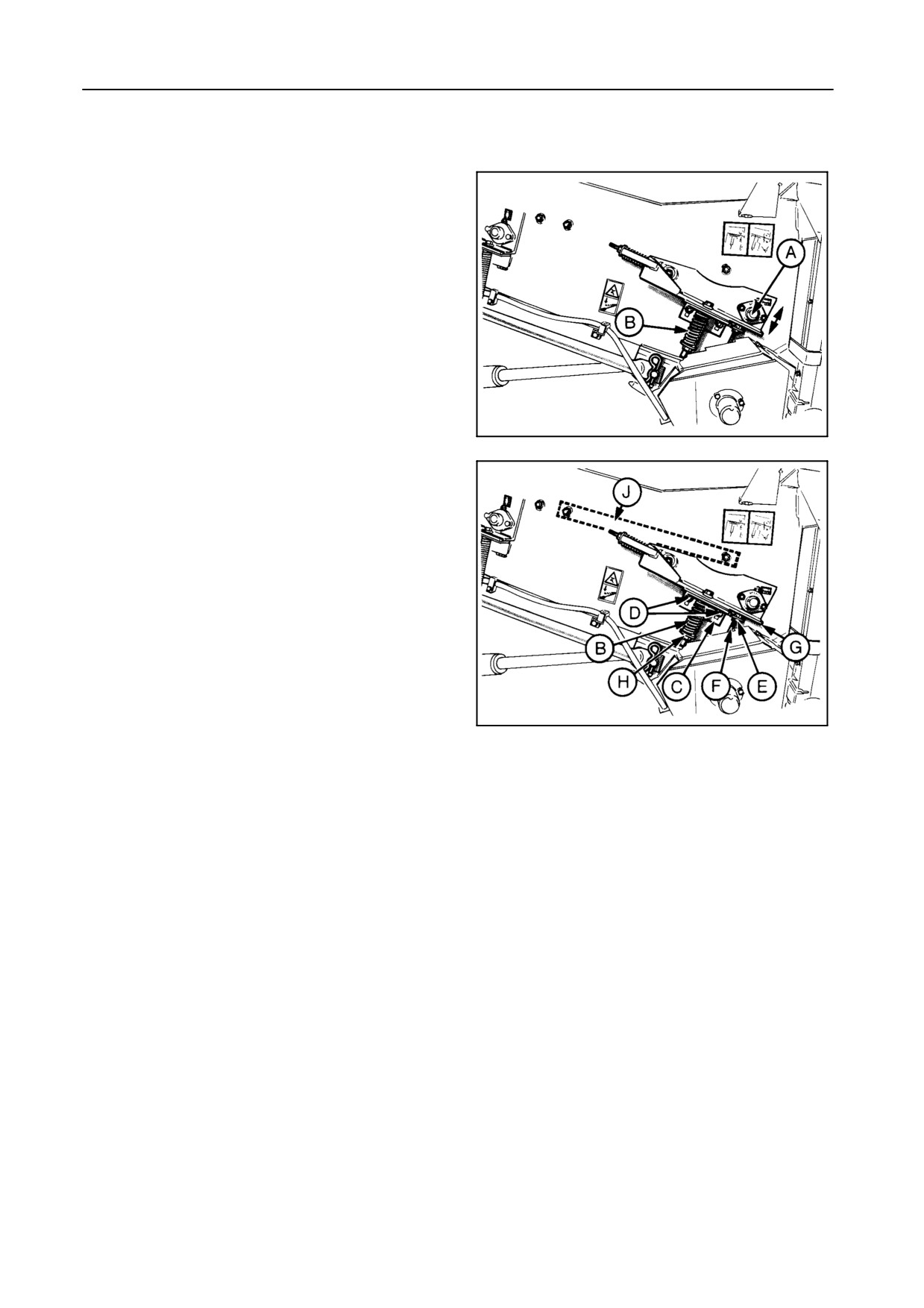
STRAW ELEVATOR ADJUSTMENT -- Figure 17
The straw elevator bottom shaft A is spring-tensioned
so that it can float according to the amount of material
being handled.
The spring tension B must be adjusted according to
the crop being harvested.
55017
17
S Models without lateral flotation -- Figure 18
For all crops other than maize:
1. Stops C must be set in the lowest position on
both sides:
Loosen nuts D and E and ease off bolt F until a
minimum clearance of 1 mm is obtained be-
55018
tween plate G and bolt F.
18
Tighten nuts D and E.
2. Adjust spring length B to 112 mm with nut H on
both sides.
For maize crops:
1. Stops C must be set in the highest position on
both sides:
Loosen nuts D and E and screw in bolt F until
stop C is in its highest position.
Tighten nuts D.
Adjust bolt F until a minimum clearance of 1
mm is obtained between plate H and bolt F.
Tighten nut E.
2. Adjust spring length B to 89 mm with nut H on
both sides.
4-18
SECTION 4
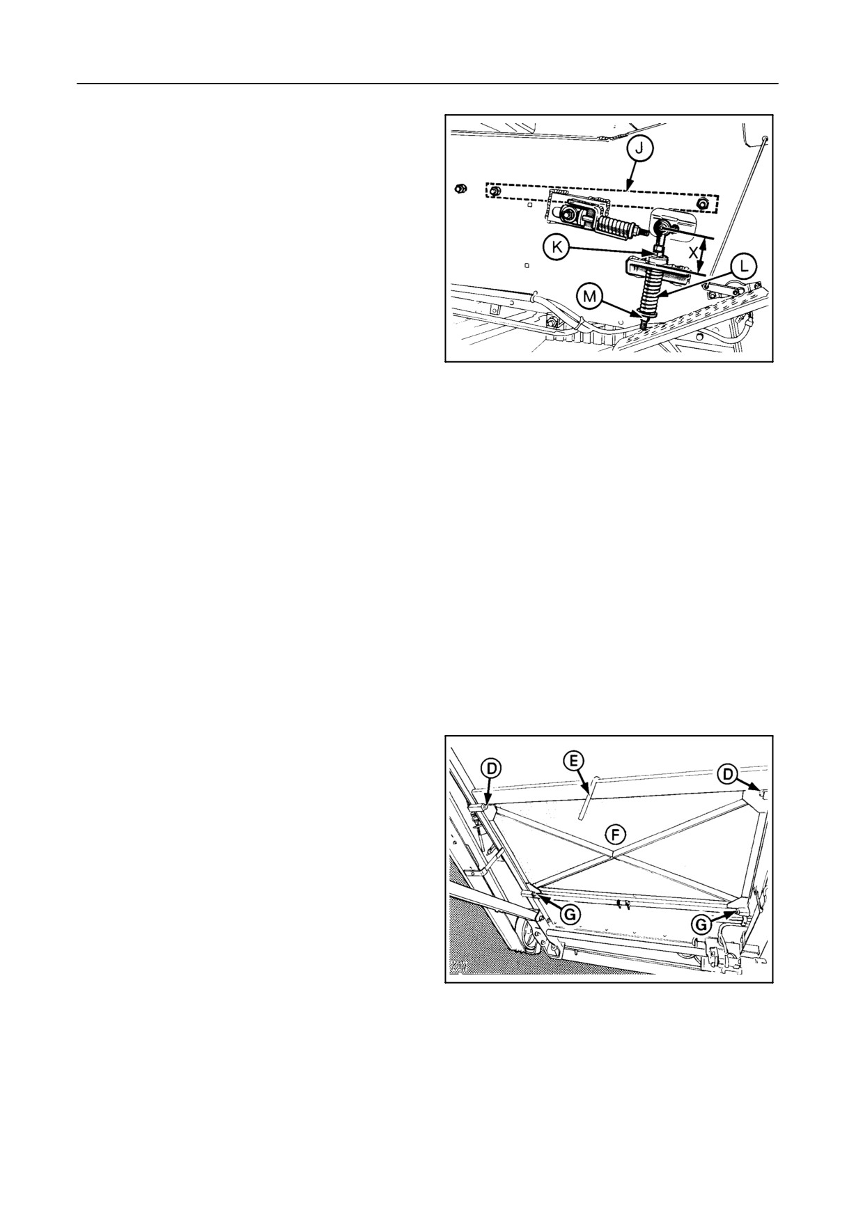
S Models with lateral flotation -- Figure 19
For all crops other than maize:
1. Adjust special nut K on both sides until dis-
tance X measures 90 mm.
2. If necessary, adjust spring L to a length of 112
mm.
Adjust with nut M.
55000
For maize crops:
19
1. Adjust special nut K on both sides until dis-
tance X measures 113 mm.
2. If necessary, adjust spring L to a length of 89
mm.
Adjust with nut M.
STRAW ELEVATOR BOTTOM PLATE -- Figure 20
The bottom plate middle section can be replaced by a
perforated access door [accessory] which is recom-
mended when threshing beans, peas or maize in or-
der to obtain a cleaner grain sample.
When the perforated access door is installed, it is pos-
sible to operate with or without the smooth bottom
plate.
To install or remove this smooth plate, proceed as fol-
lows:
1. Remove bolts D.
30241
2. Loosen bolts G.
20
3. Unscrew lever E and open the access door F.
4. Install or remove the smooth bottom plate on top of
the perforated access door F.
4-19
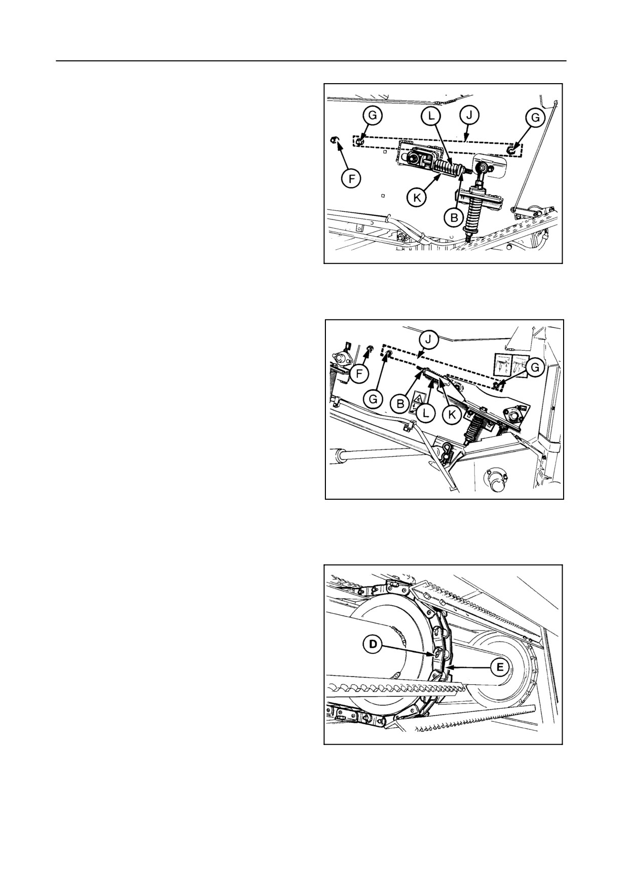
FIELD OPERATION
STRAW ELEVATOR INTERMEDIATE PLATE EX-
TENSION -- Figures 21 to 25
For all crops other than maize, install the straw eleva-
tor intermediate plate extension J to avoid straw
blockages.
When harvesting maize, the intermediate plate exten-
sion J should be removed.
55001
21
Lateral float straw elevator
Proceed as follows:
1. Loosen nuts B on both sides to slacken the straw
elevator chains.
2. Move the straw elevator bottom shaft to the rear.
3. Remove dust plates C at the front of the straw ele-
vator.
52019
22
Fixed straw elevator
4. Remove cotter pin D and open chains E.
5. Attach a rope to the upper end of the chains to fa-
cilitate reassembly afterwards.
6. Open the bottom access door M (refer to the previ-
ous paragraph).
7. Loosen nuts F on both sides.
8. Remove bolts G on both sides
57025
9. Remove the small intermediate plate H, if applica-
23
ble.
4-20
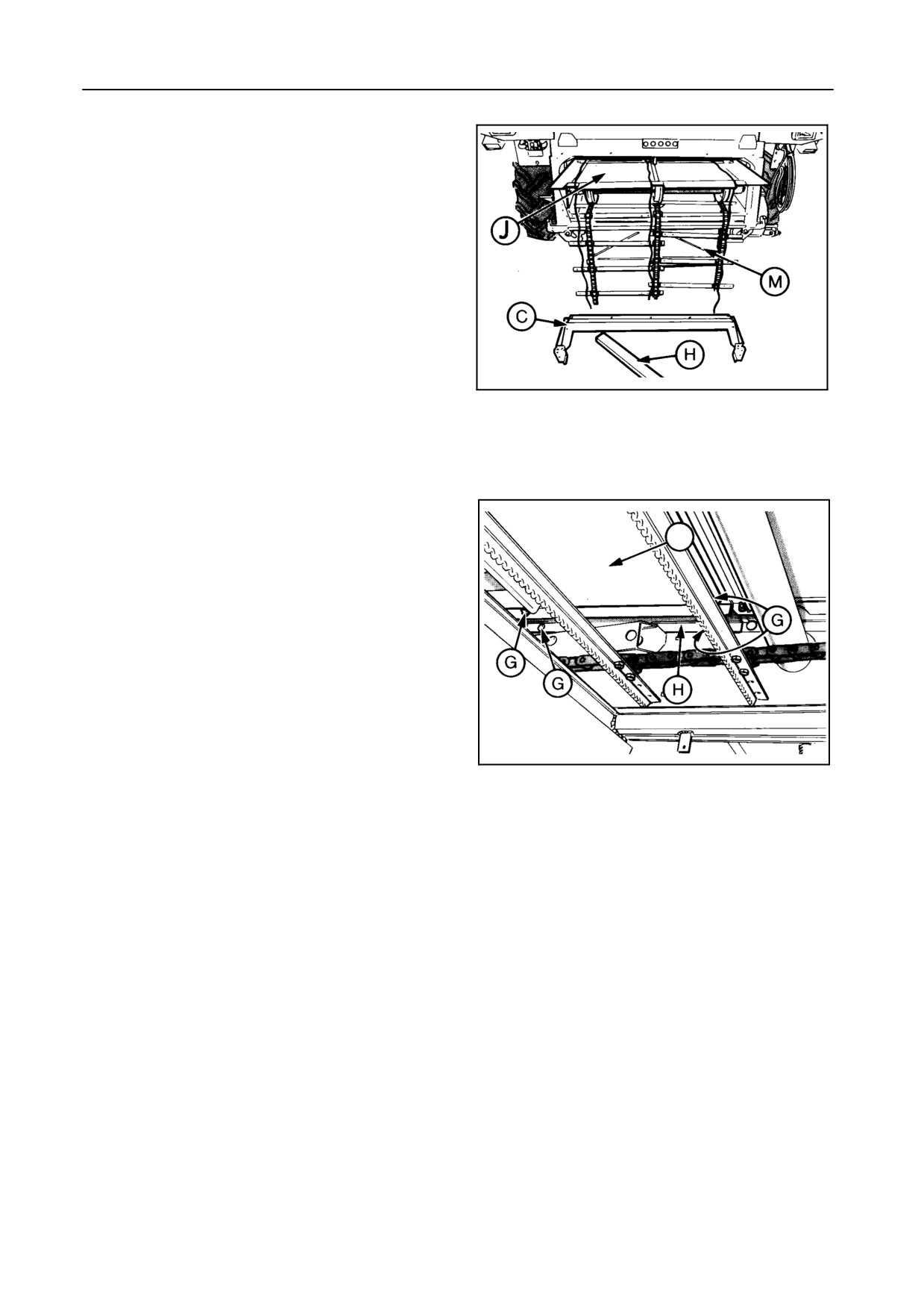
SECTION 4
10. Remove intermediate plate extension J.
11. Close the bottom access door.
12. Reassemble chains E with the cotter pin as
shown.
13. Tighten nuts F.
14. Readjust the chain tension (spring length L = indi-
cator length K).
55006
24
15. Reinstall dust plates C at the front of the straw
elevator.
A
55007
25
4-21
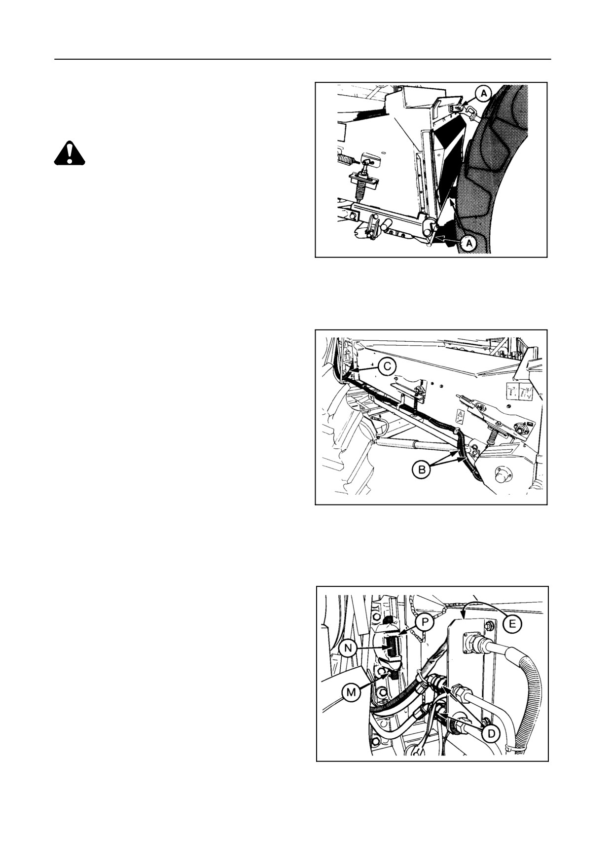
FIELD OPERATION
STRAW ELEVATOR REMOVAL -- Figures 26 to 33
CAUTION:
Be careful when doing this job: the straw
elevator weighs about 1,000 kg.
The tractor must have a lift capacity of
minimum 2,500 kg at approximately 1 m
behind the linkages.
30262
26
The straw elevator is fitted with 3 attaching points A
which facilitate removal of the straw elevator by
means of a tractor (minimum + 74 kW/100 hp).
Proceed as follows:
1.
Install the middle attaching point A, located behind
the left-hand straw elevator guard, onto the straw
elevator.
2.
Models TX62-63
55008
Disconnect the electric cables B from the reverser
27
motor and remove it from the straw elevator.
Disconnect the earth connection C.
Models TX64PLUS-65PLUS-66-67-68-68PLUS
Disconnect the hydraulic quick-couplers D of the
hydraulic reverser and plug E on the left-hand
side.
Disconnect the hydraulic quick-couplers F of the
lateral float system [if installed] on the right-hand
side.
3.
Disconnect electric wire S of the header height
sensor.
4.
Attach the straw elevator to the tractor with the
55009
three attaching points A and secure the pins with
28
cotter pins.
4-22
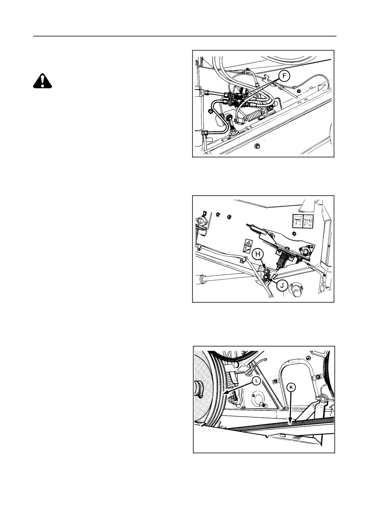
SECTION 4
5. Remove cotter pins H, pins J, the safety latch(es)
and washers from both cylinders.
CAUTION:
Be careful: the cylinder is heavy.
6. Remove the header drive belt K from drive pulley
L.
7. Unscrew bolt M and remove keys N and bracket
halves P on both sides.
55010
8. Move the tractor slowly forward while slightly low-
29
ering the straw elevator on the tractor.
To attach the straw elevator to the combine, proceed
in reverse order, but make sure to rest the header
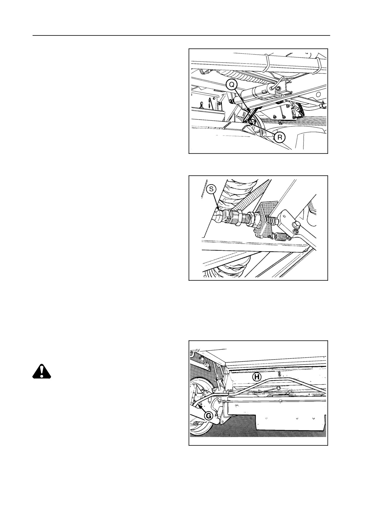
height sensor lever Q on roll R of the straw elevator.
IMPORTANT:
Avoid possible oil contamination by properly fit-
ting the blanking plugs into the hydraulic quick-
couplers.
55016
30
30214
31
4-23
FIELD OPERATION
55014
32
42825
33
STONE TRAP -- Figures 34 and 35
The stone trap must be cleaned out at least once a
day, and more often in damp crop or stony conditions.
CAUTION:
Disengage the threshing mechanism, lift
the header to its maximum height, place
the header safety latch over the cylinder
rod and stop the engine.
To clean out the stone trap, swing lever G upwards as
shown. This will open the stone trap front cover H .
30243
34
4-24