New Holland TX62, TX63, TX64 Plus, TX65 Plus, TX66, TX67, TX68, TX68 Plus. Operator's Manual - page 4
SECTION 4
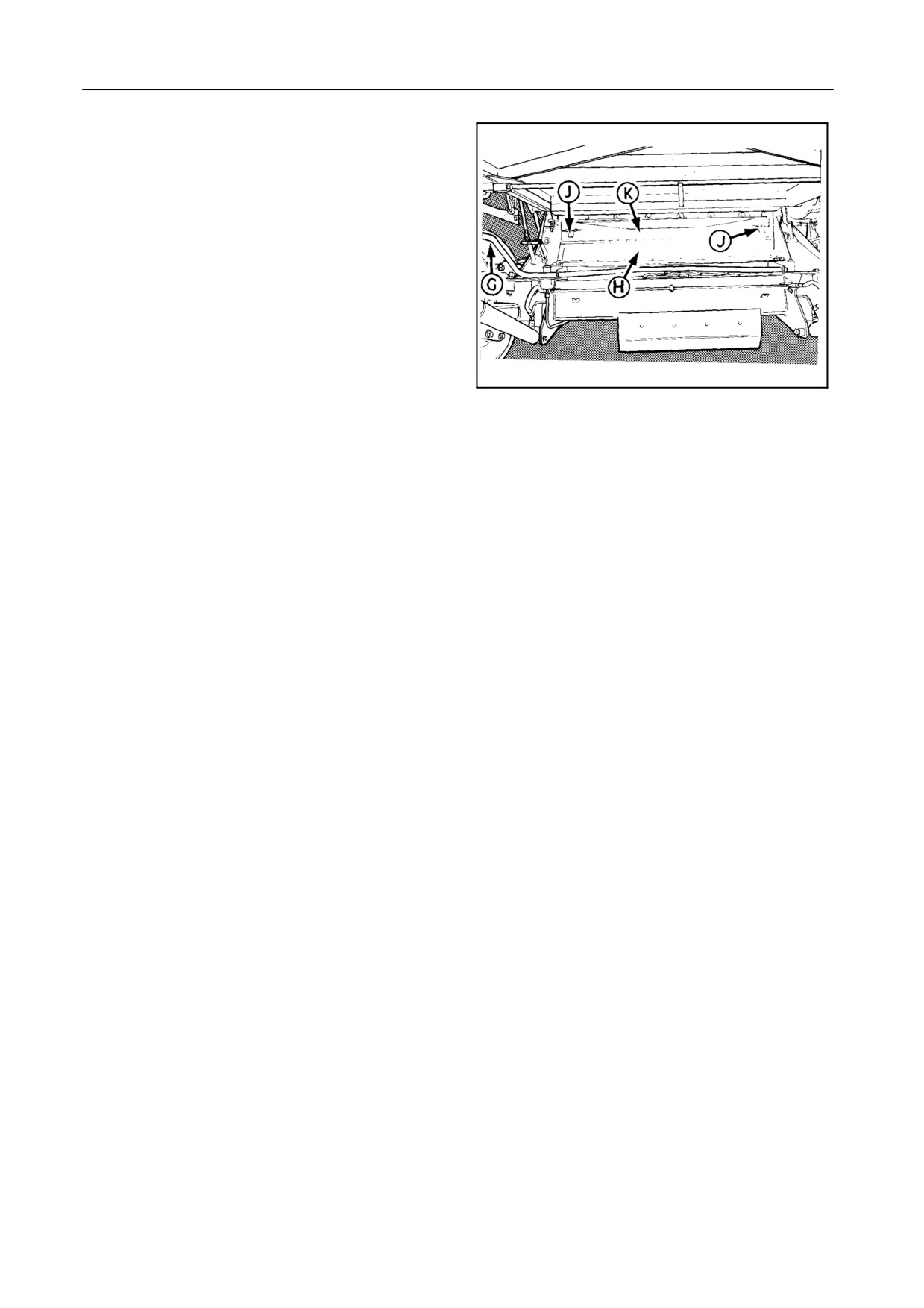
When the stone trap is completely clean, close it by
moving lever G completely downwards.
When threshing maize or rice, the stone trap should
be covered with a plate included in the maize or rice
threshing equipment.
30242
35
GRAIN PAN ACCESS -- Figure 35
To gain access to the grain pan at the front, proceed
as follows:
1. Open the stone trap as described in the previous
paragraph.
2. Slide the levers J towards the centre of the stone
trap.
3. Pivot plate K forwards.
4. Proceed in reverse order to reinstall plate K.
5. Close the stone trap.
To gain access at the sides, refer to paragraph
headed ‘‘Access to drum and concave”.
4-25
FIELD OPERATION
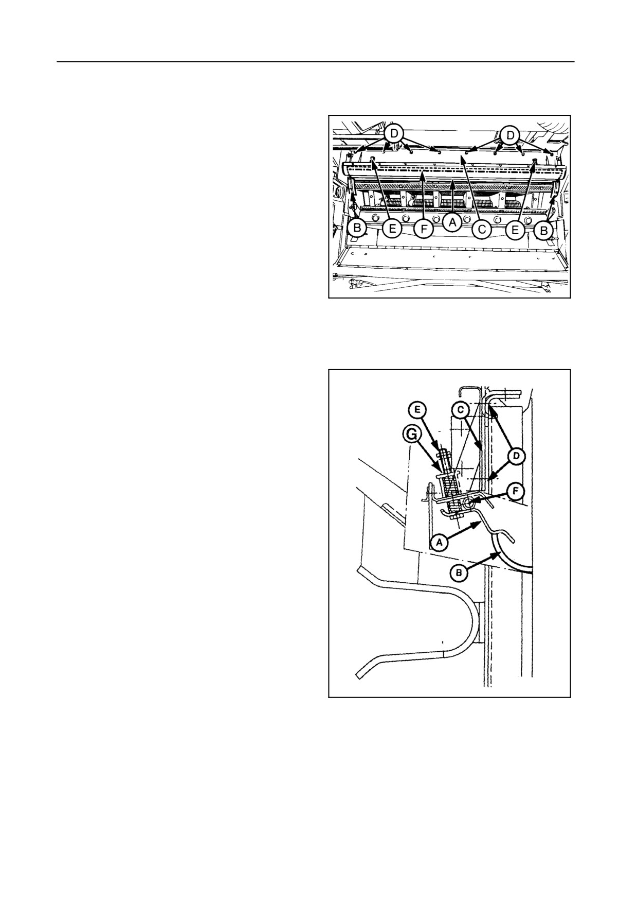
ANTIDUST PLATE -- Figures 36 and 37
Remove antidust plate A and antiwrap shields B when
operating in maize.
Proceed as follows:
1. Remove the straw elevator (refer to paragraph
headed ‘‘Straw elevator removal’’).
2. Unscrew bolts D and remove plate C to which anti-
dust plate A is fitted.
3. Unscrew bolts E, remove rod F and antidust plate
A.
55011
4. Reinstall plate C.
36
5. Remove antiwrap shields B on both sides.
When reinstalling antidust plate A and antiwrap
shields B, proceed in reverse order of the removal se-
quence and adjust nuts G until there is a clearance of
3 mm between the plate and the drum rasp bars.
52438
37
4-26
SECTION 4
DRUM AND CONCAVE
PARAMETERS
Parameters for selecting the drum speed and con-
cave clearance are:
S Type of crop
S Crop maturity and variety
S Moisture content
S Volume of straw and grain
S Weed contamination
FUNDAMENTALS OF ADJUSTMENT
S Maximum drum speed and minimum concave
clearance give maximum threshing efficiency.
S If grain is damaged or straw is chopped exces-
sively, reduce the drum speed and/or increase the
concave clearance.
S If grain is not fully separated from the ears, in-
crease the drum speed and/or reduce the concave
clearance.
S If plugging or wrapping occurs, increase the drum
speed.
DRUM SPEED
The drum speed is adjustable electrically from the op-
erator’s platform and can be read from the InfoView
monitor (see further).
IMPORTANT:
Actuate the drum variator switch only with the
threshing mechanism running.
4-27
FIELD OPERATION
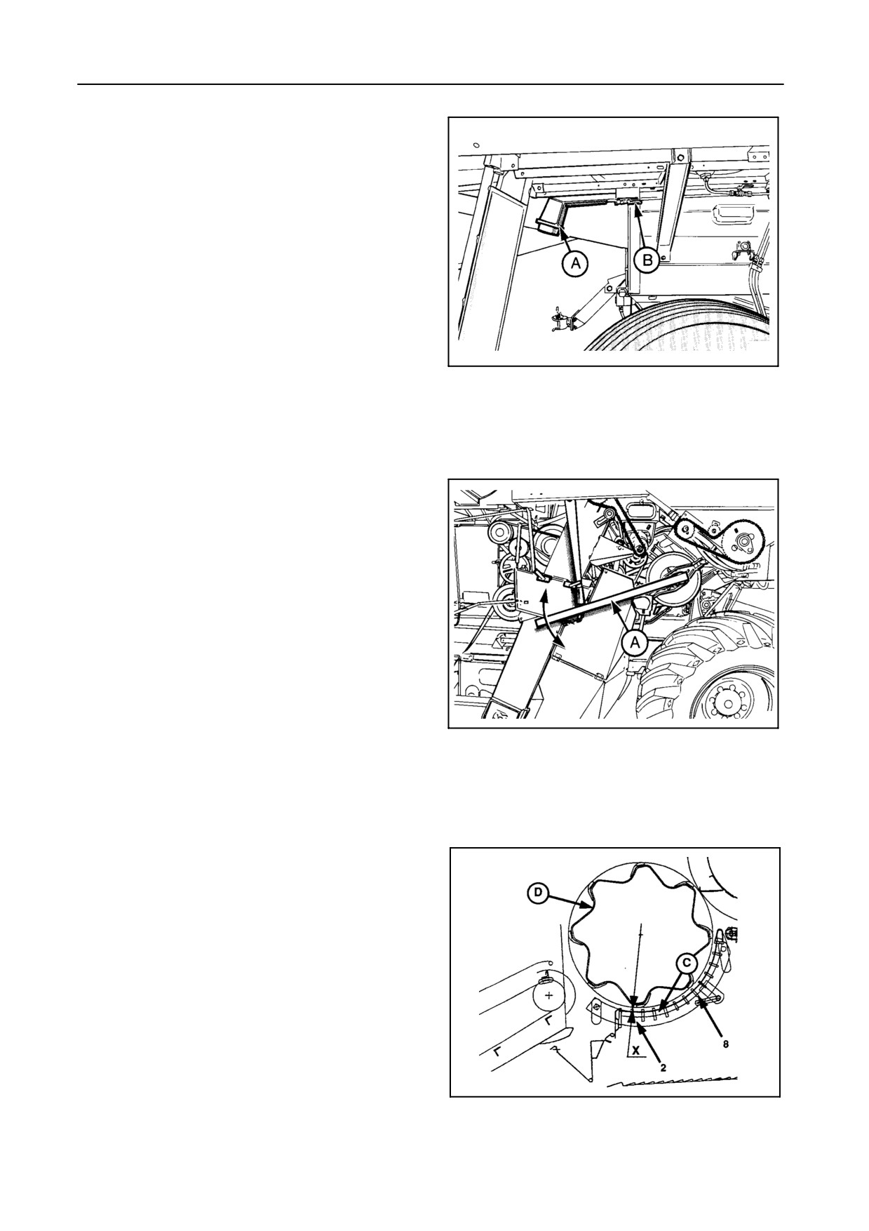
DRUM BLOCKAGE -- Figures 38 and 39
Should the drum become blocked, proceed as fol-
lows:
1. Lower the concave to its lowest position and try to
unblock by engaging the threshing mechanism at
low engine speed.
2. If this is ineffective, try to unblock the drum by us-
ing the drum socket wrench A (i.e. when the stan-
dard drum variator is fitted).
55025
The drum socket wrench A is located under the
38
fuel tank and is secured with latch B.
CONCAVE CLEARANCE
S Adjustment from the operator’s seat:
Models TX62-63:
Manual adjustment with the concave setting lever.
Models TX64PLUS-65PLUS-66-67-68-68PLUS:
Electrical adjustment (refer to Section 2 - OPERA-
TION)
55029
S Mechanical adjustment:
Refer to paragraph headed ‘‘Changing the clear-
39
ance mechanically’’ further in this section.
Basic settings -- Figure 40
When the combine is shipped from the factory, con-
cave C is set parallel to drum D (front and rear) with a
clearance X of 10 mm.
Models TX62-63:
The concave clearance X of 10 mm is reached with
the concave setting lever in position 2 on the quad-
rant, i.e. the second highest position.
Models TX64PLUS-65PLUS-66-67-68-68PLUS:
The concave clearance can be read from the In-
foView monitor when the rpm mode is selected. Refer
51786
to paragraph headed ‘‘InfoView monitor’’.
40
4-28
SECTION 4
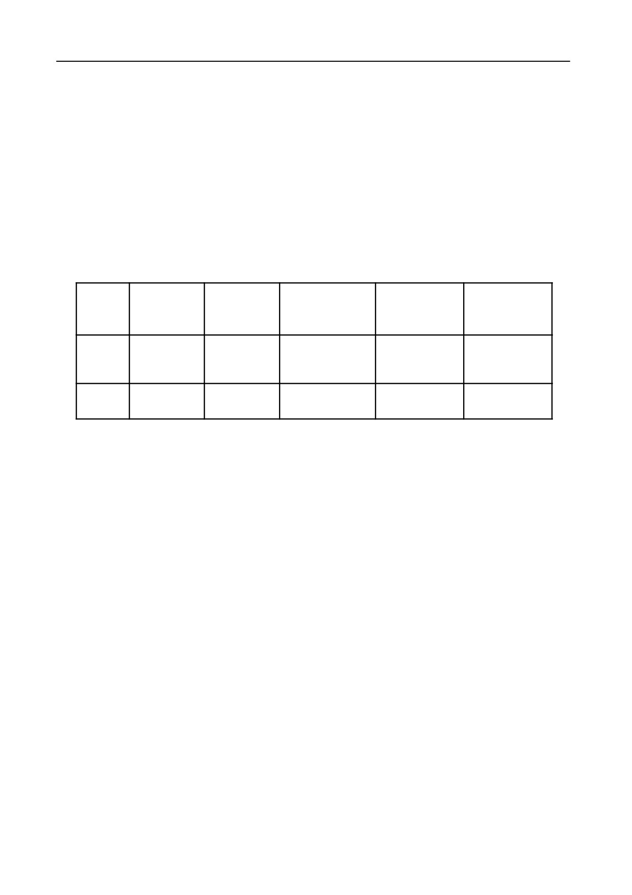
This concave setting will be satisfactory for most ce-
real crops. However, if greater threshing action is
needed, the clearance at the rear can be reduced to 8
mm.
When harvesting maize, concave C can be set to a
clearance of 25 mm at the second (2) concave bar
and 30 mm at the eighth (8) concave bar.
For models TX62 and 63, this is measured with the
concave setting lever in position 7 on the quadrant.
CROP
CONCAVE
LEVER
RPM DISPLAY
2ND BAR
8TH BAR
TYPE
POSITION
(TX64PLUS-65PLUS-
CLEARANCE
CLEARANCE
(TX62-63)
66-67-68-68PLUS)
Cereal
Cereal
2
10 mm
10 mm
10 mm
crops
Maize
Maize
7
25 mm
25 mm
30 mm
If excessive grain damage is experienced when
harvesting maize, increase the concave clear-
ance X.
IMPORTANT:
If the Combine was set up to harvest maize,
concave C will be bolted in position and it will
not be possible to adjust the concave clear-
ance X neither manually (models TX62-63),
nor electrically
(models TX64PLUS-65PLUS-
66-67-68-68PLUS), unless the hardware is loos-
ened first (see further).
4-29
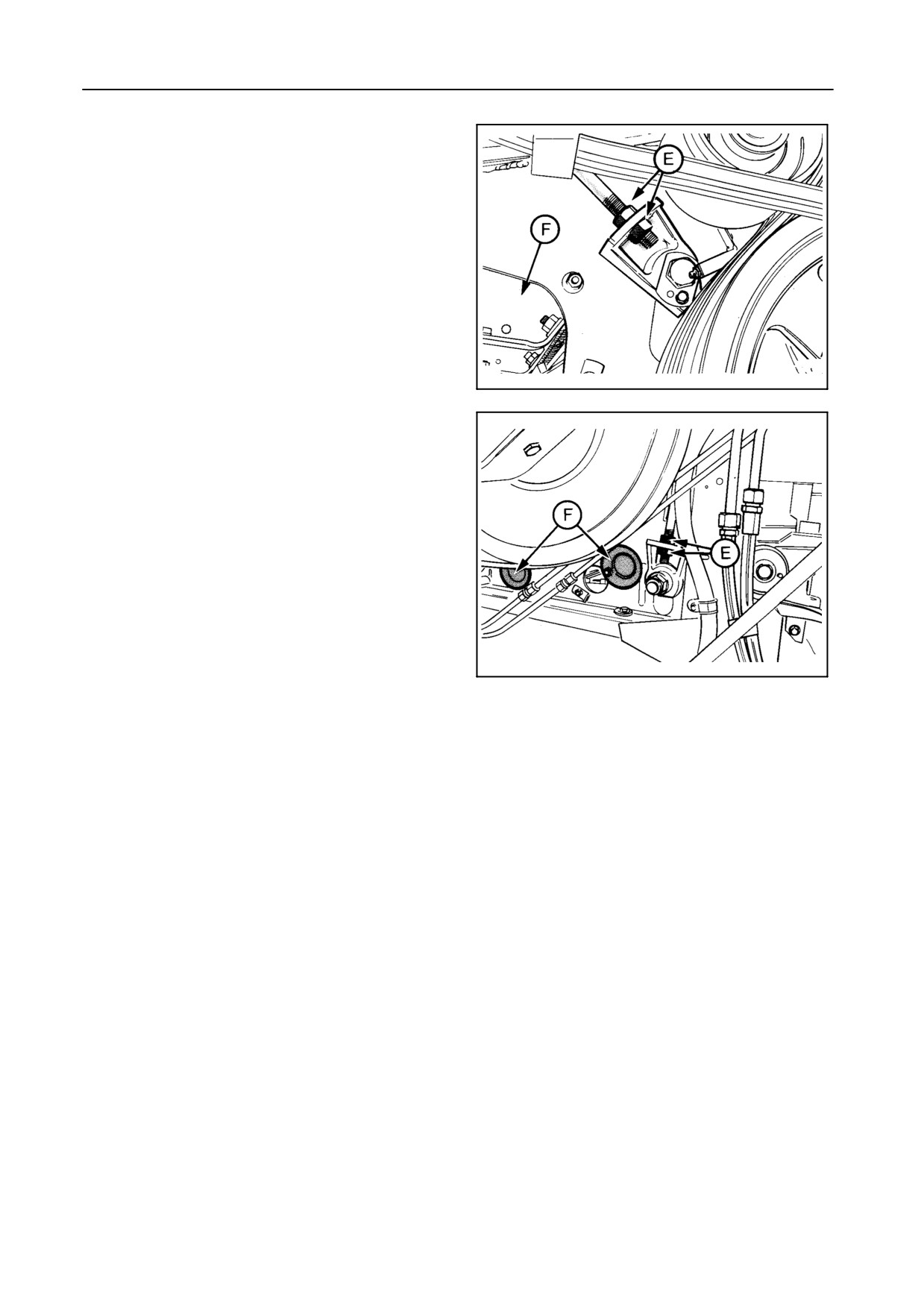
FIELD OPERATION
Changing the concave clearance mechanically --
Figures 41 and 42
To change the concave clearance at the front or at the
rear, adjust nuts E on both sides of the combine.
Figure 41: Right-hand side - Front adjustment.
Figure 42: Left-hand side - Rear adjustment.
55022
Check the clearance on the second and eighth con-
cave bar. To gain access to the concave bar, open
41
covers B.
IMPORTANT:
After carrying out any adjustments to the con-
cave, ensure that the concave bars are set par-
allel to the drum rasp bars.
55024
42
Securing the concave position -- Figures 43 and 44
When harvesting maize, the concave has to be bolted
in position after first adjusting the clearance to 25 mm
at the front and 30 mm at the rear.
Proceed as follows:
1. Models TX62-63
Ensure that the concave setting lever is in position
7 on the quadrant on the operator’s platform.
Models TX64PLUS-65PLUS-66-67-68-68PLUS
Ensure the concave is adjusted until a read-out of
25 mm is obtained on the InfoView monitor.
4-30
SECTION 4
2. Check on the second bar if the 25 mm clearance
and on the eighth bar if the 30 mm clearance is still
valid. If not, adjust mechanically. Refer to the pre-
ceding paragraph.
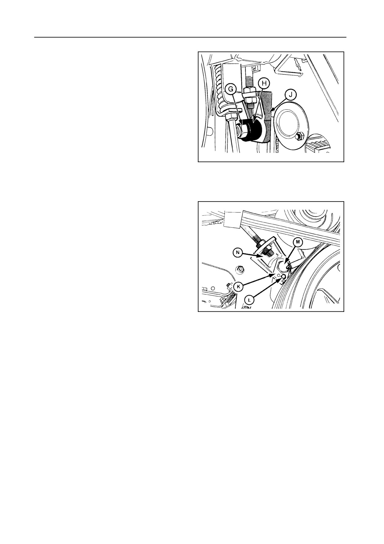
3.
Figure 43
At the front: Tighten lock nut G completely so that
bushing H presses block J against the frame. Pro-
ceed in the same way on both sides.
4.
Figure 44
55023
At the rear: Remove lock plate K with bolt L.
43
Tighten bolt M completely so that block N is
pressed against the frame. Reinstall lock plate K
and bolt L. Proceed in the same way on both sides.
IMPORTANT:
For operation in cereal crops:
S At the front, lock nut G should not be tight-
ened completely and it should be possible
to turn bushing H freely.
S At the rear, loosen bolt M one turn after
tightening, before installing lock plate K.
In this case, the concave is not bolted in posi-
tion, but it is adjustable with the concave set-
55022
ting lever on the operator’s platform (models
44
TX62-63) or electrically
(models TX64PLUS-
65PLUS-66-67-68-68PLUS).
4-31
FIELD OPERATION
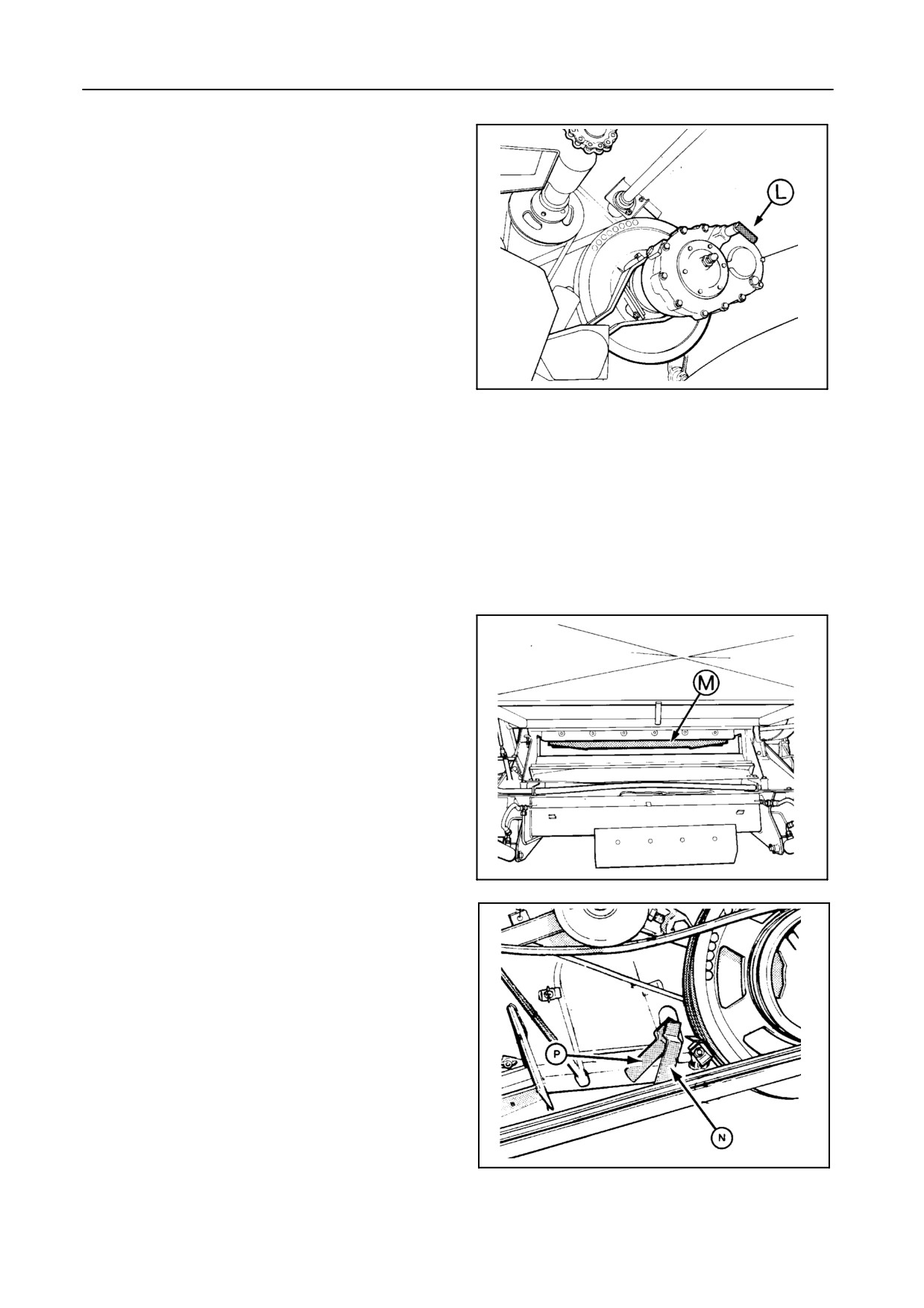
DRUM SPEED REDUCER [if installed] -- Figure 45
Using the reduction gearbox, two speed ranges on
the drum can be obtained:
S From 385 rpm to 1140 rpm (direct drive)
This high speed range is used when harvesting
regular crops (i.e. cereal crops, maize, etc.). To
engage this range, push lever L towards the
gearbox.
S From 190 rpm to 560 rpm
42969
This low speed range is used when harvesting
45
crops with fragile grains (i.e. dry maize, beans,
etc.). To engage this range, pull lever L out-
wards.
NOTE:
When changing speed with lever L, it is impor-
tant to turn the drum variator sheaves manually
to ensure proper engagement of the gears.
DE-AWNING PLATES -- Figures 46 and 47
De-awning plates increase the rubbing action of the
drum and concave when threshing winter barley or
difficult to thresh crops.
Two de-awning plates M are attached to the concave
with hinges and can be locked in position with levers N
and P.
Lever N operates the front de-awning plate and lever
P operates the rear de-awning plate.
42964
46
Only close the rear de-awning plate M if really neces-
sary, as partially closing off the concave inevitably
means loss of capacity.
20928
47
4-32
SECTION 4
DRUM AND CONCAVE TYPE USE
S When harvesting cereals, it is advisable to use a
standard or universal drum and a cereals con-
cave.
S When harvesting maize, a standard or universal
drum and a maize concave should be installed.
S When harvesting rice, a universal drum with peg
tooth bars and a rice concave should be installed.
If needed, the concave and/or universal drum can be
converted for harvesting other crops
(e.g. when
switching from cereals to maize).
Have this job carried out by your New Holland dealer.
BEATER
The beater, which runs at 2/3 of the drum speed, is ac-
cessible through the inspection opening S in the grain
tank.
The beater can be equipped with either:
S
5 adjustable stripper plates for cereals, or
S
5 toothed bars for maize, or
S
10 toothed bars for rice
To change from one equipment to another, remove
bolts W (Fig. 48), change the equipment and reinstall
bolts W.
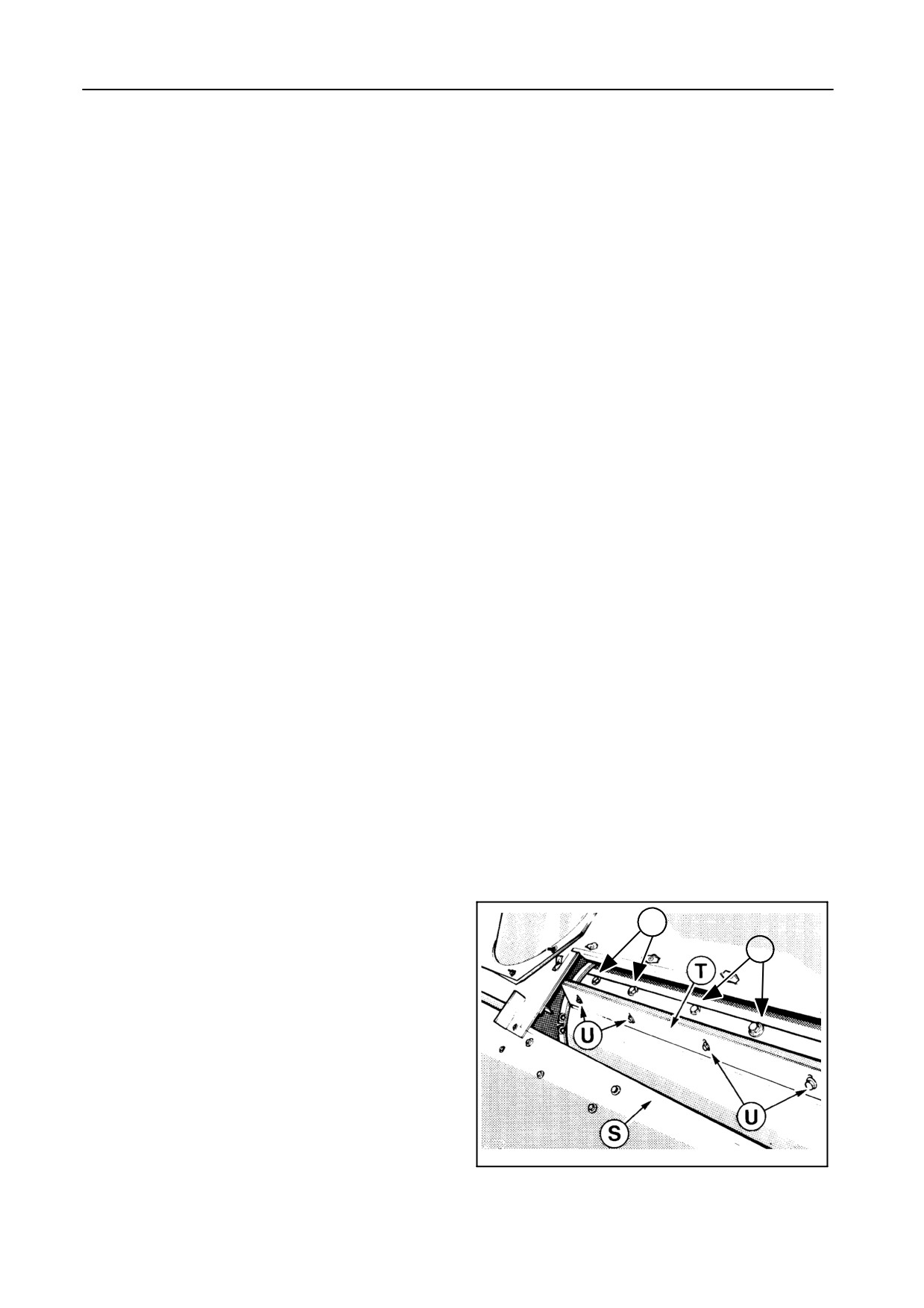
ADJUSTABLE STRIPPER PLATES -- Figure 48
w
w
For correct adjustment of the beater stripper plates,
the beater drive belt has to be removed.
Adjust the plates T by loosening bolts U and setting
the stripper plates as close as possible to the drum
rasp bars without touching them.
When carrying out this job, first search for the closest
rasp bar. Retighten bolts U.
20950
48
4-33
FIELD OPERATION
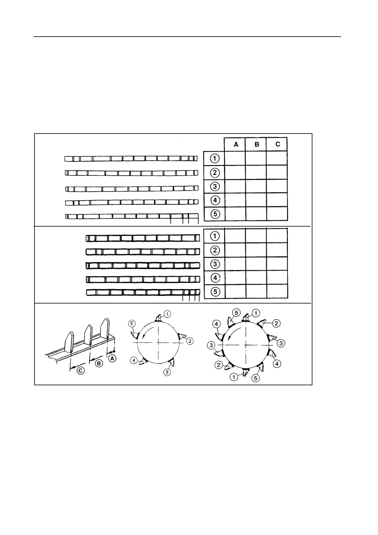
TOOTHED BEATER BARS (5 or 10) -- Figure 49
The bars have to be installed in a certain sequence as
shown.
Measure the right-hand side of the bars to know the
correct sequence and use the bolts V to install the
bars.
TX66-67-68-68PLUS
15
81
183
15
106.5
265
15
132
290.5
15
81
208.5
81
157.5
316
C B A
TX62-63-64PLUS-65PLUS
15
183
341.5
15
106.5
265
81
132
290.5
15
81
208.5
15
81
157.5
C
BA
52670
49
4-34
SECTION
4
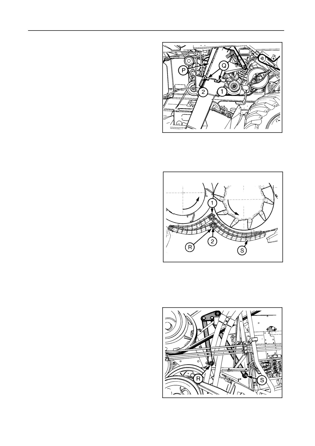
MULTI-THRESH SYSTEM -- Figures 50 to 52
With the multi-thresh system the beater and rotary
separator concaves can be set in two positions.
Closed position (1): Lever P forwards.
This position is recommended for all crops as the rub-
bing effect is high.
Open position (2): Lever P rearwards.
In this position the rubbing is less aggressive which is
recommended in brittle straw and rape seed.
If necessary, reduce the combining speed to avoid
grain losses.
55026
50
Secure lever P with latch Q.
For maize:
Set the concaves in closed position and tighten nuts R
and S on both sides.
For cereals:
Loosen nuts R and S half a turn after tightening, so the
concaves are adjustable with lever P.
55030
51
55021
52
4-35
FIELD OPERATION
ROTARY SEPARATOR
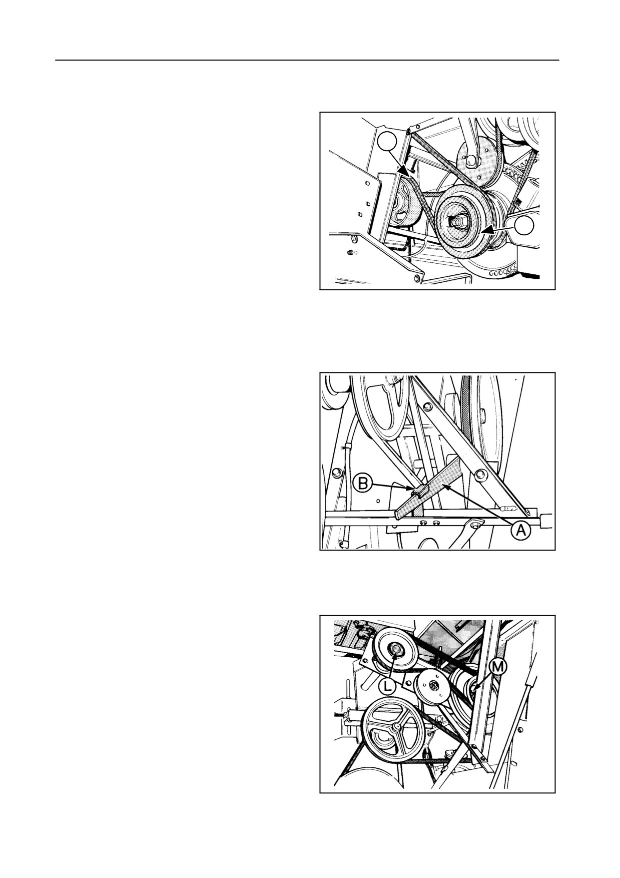
ROTARY SEPARATOR SPEED -- Figures 53 and 54
The rotary separator is driven by pulley V which has a
C
double groove for an alternative speed:
S
760 rpm is the factory-set speed which is suit-
able for most crops such as barley, oats, rye,
wheat, rice, grass seed, etc.
S
400 rpm is for harvesting maize, beans, peas,
V
soya, sunflower, oil seed rape, etc.
To change the speed, proceed as follows:
40843
1. Move lever A out of hook B and upwards.
53
This will move the idler C downwards and loosen
the belt tension.
2. Install the belt in the other grooves of both pulleys.
3. Move lever A downwards and secure the lever in
hook B as shown.
4. Check the belt tension and adjust, if necessary
(refer to Section 5 - ADJUSTMENTS AND MAIN-
TENANCE, paragraph headed
‘‘Belts and
chains’’).
The rotary separator is accessible through the cover
which is situated underneath the grain tank.
CONCAVE POSITION
Refer to paragraph headed ‘‘Multi-thresh system’’.
40845
54
STRAW FLOW BEATER [if installed] -- Figure 55
The function of the Straw Flow beater L is to improve
the combine throughput capacity in specific condi-
tions (heavy green, damp straw).
On combines equipped with a Straw Flow beater L
and operating in severe crop conditions (very dry or
brittle), the rotary separator M, and so the Straw Flow
beater L, can be set on low rpm speed (400 rpm) if the
straw breaks up too easily.
30217
55
4-36
SECTION 4
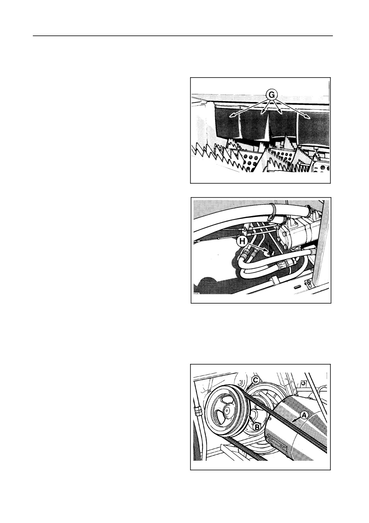
STRAW RETARDING CURTAIN -- Figures 56 and 57
A straw retarding curtain G is positioned at the rear of
the rotary separator and above the straw walkers to
prevent the grain from being thrown out of the com-
bine by the rotary separator.
Curtain G can be raised with chain H to improve the
material flow in heavy crop conditions.
20947
56
20926
57
CLEANING SHOE -- Figure 58
The complete cleaning shoe, consisting of shaker
shoes with sieves, cleaning fan and returns system, is
driven by belt A. The drive pulley has a double groove
for an alternative speed of the cleaning shoe drive:
S
600 rpm (groove B) is the factory-set speed
which is suitable for most crops.
S
540 rpm (groove C) is for harvesting brittle
crops and all kinds of small seeds (rape seed,
grass seed, sunflower, etc.)
30151
58
4-37
FIELD OPERATION
SIEVES
SIEVE OPENINGS -- Figures 59 and 60
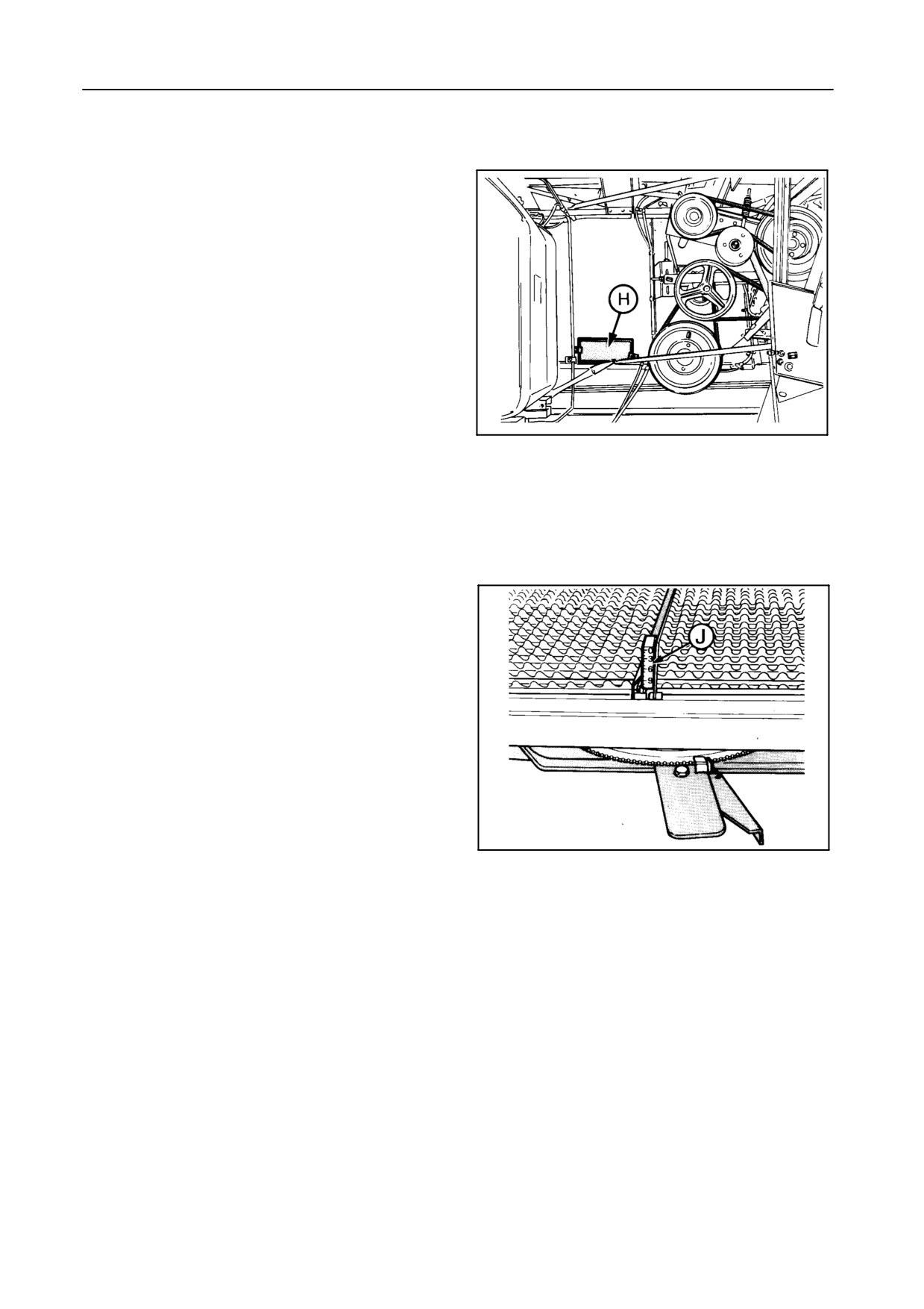
Adjust the opening of the presieve, according to the
grain size, with the lever on the right-hand side of the
sieve which is accessible after removing cover H.
The 6 mm opening is the recommended position for
most cereal crops and sunflower.
When operating in damp conditions, a larger opening
(9 or 12 mm) can be recommended to avoid plugging
of the presieve.
55027
For small seeds, a 3 mm position can be chosen.
59
For high moisture maize, a presieve is available as an
accessory.
Adjust the openings of the upper and lower sieve, ac-
cording to the grain size, with the levers at the rear of
the sieves. Operate with the sieves open as wide as
possible, consistent with producing a clean sample.
The lower sieve is equipped with a sieve opening indi-
cator J.
The rear part of the upper sieve can be adjusted sepa-
rately. It may be necessary for the rear part to be
opened a few millimetres more than the upper sieve
opening to prevent loss of the returns, particularly
when harvesting wheat.
When harvesting maize, keep the upper sieve closed
as much as possible to sieve all the grain and to pre-
42966
vent the maize cobs from passing through the sieve
60
and entering the grain tank.
SIEVE POSITION
The upper sieve is normally fitted in the lower position.
The upper position is recommended when harvesting
maize.
The lower sieve is set at the factory in the lower
position. The upper position can be used if a higher
capacity with less clean grain sample is required.
4-38
SECTION 4
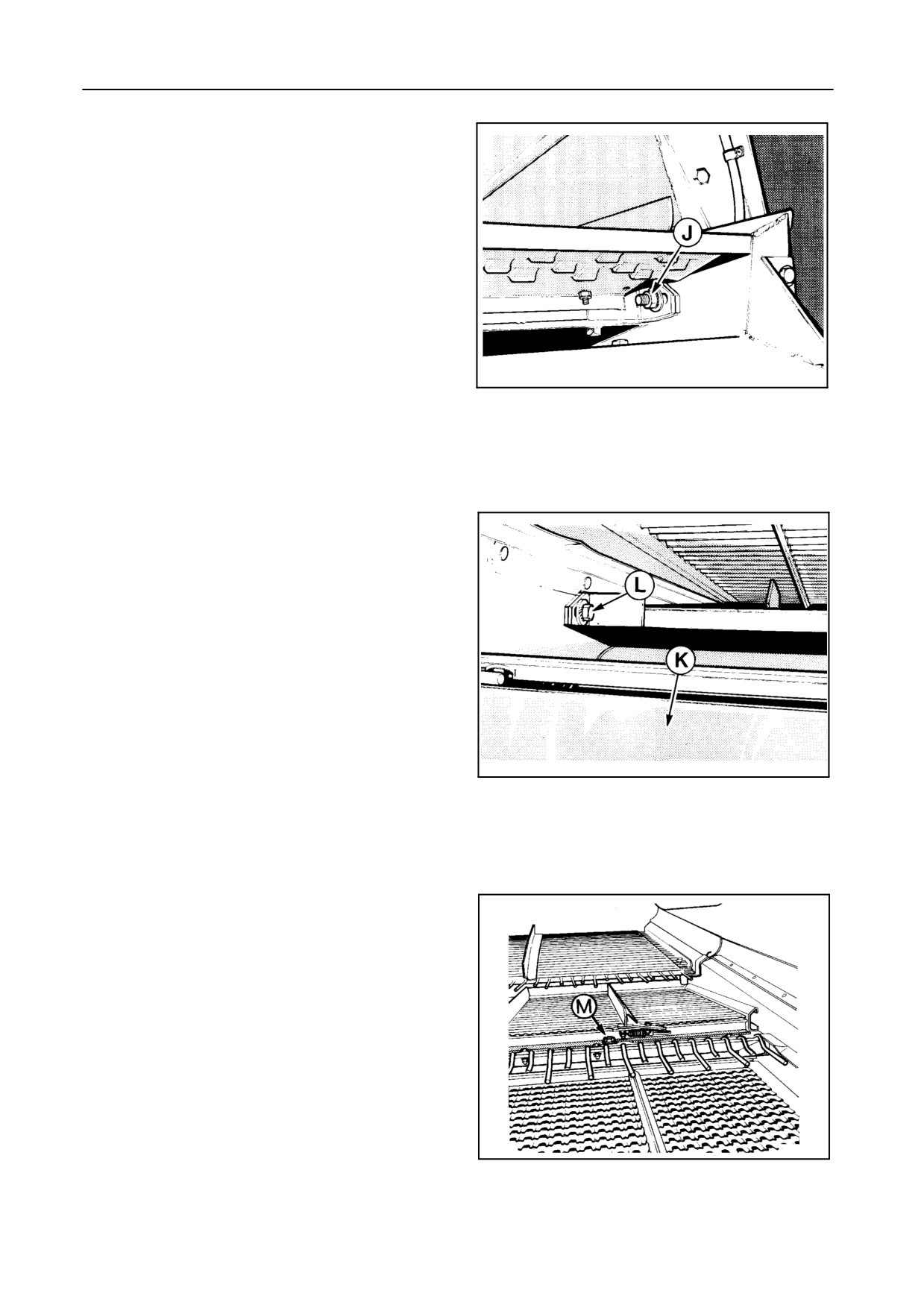
SIEVE REMOVAL -- Figures 61 to 63
1. Remove bolts J on both sides and remove the up-
per sieve.
On models TX66-67-TX68-TX68PLUS, the upper
sieve consists of two sieve halves.
2. Open cover K , remove bolts L and remove the
lower sieve. Adjust the sieve position by hand if the
grain loss sensor prevents the removal of the
sieve.
On models TX66-67-TX68-TX68PLUS, the lower
sieve consists of two sieve halves.
20946
3. Remove bolts M and take out the presieve.
61
20945
62
42962
63
4-39
FIELD OPERATION
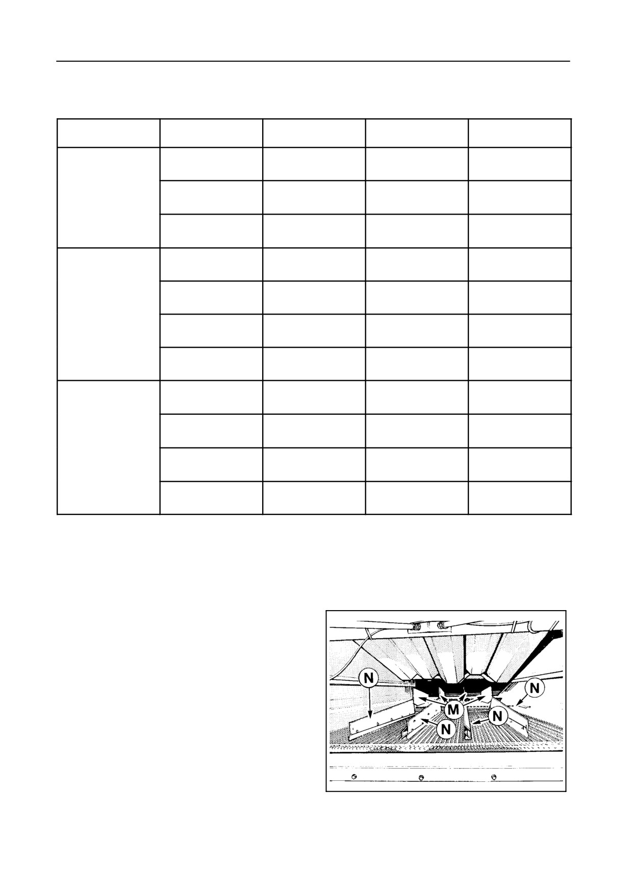
TYPES OF SIEVES AVAILABLE
Sieves
Type
Crops
Positions
Opening
Hart Carter
Cereals
Fixed
Adjustable
1- 5/8’’
Maize
Presieve
New Holland
Cereals
Fixed
Adjustable
1- 1/8’’
Maize
Graepel sieve
Corn Cob Mix
Fixed
Fixed
52 mm
Hart Carter
Cereals
Two(1)
Adjustable(2)
1- 1/8’’
Hart Carter
Maize
Two
Adjustable
Upper sieve
1- 5/8’’
Adjustable Peter-
Oil seed rape
Two
Adjustable
sen sieve 1-1/8’’
Graepel sieve
Corn Cob Mix
Two
Fixed
80 mm
Hart Carter
Cereals
Two(1)
Adjustable
13/16’’
Maize
Hart Carter
Maize
Two
Adjustable
1-1/8’’(3)
Lower sieve
Round hole sieve
Maize
Two
Fixed
16 mm dia.
Round hole sieve
Maize
Two
Fixed
18 mm dia.
(1) The lower position is the factory-installed position.
(2) The rear part is independently adjustable.
(3) Upper sieve used as cleaning sieve.
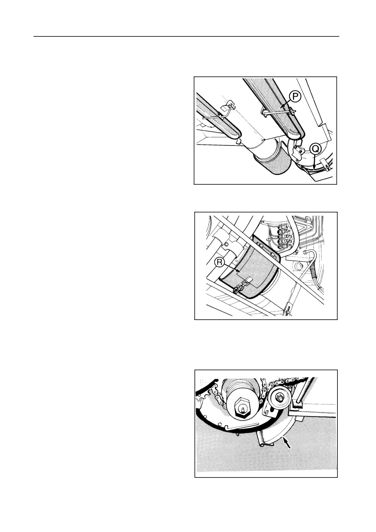
HILLSIDE DIVIDERS (units with fixed cleaning
shoe only) -- Figure 64
When operating in hilly conditions, hillside dividers
can be installed on the presieve M and on the upper
sieve N to ensure an even distribution of the material.
When constantly working in flat field conditions, it is
20944
recommended not to use these divider plates.
64
4-40
SECTION
4
CLEANING FAN
The cleaning fan speed can be adjusted electrically
from the operator’s platform and can be read from the
InfoView monitor.
Change the fan rpm only when the machine is run-
ning and adjust it to suit the nature of the crop, chaff
load and moisture content. A grass seed variator kit
can be installed to obtain a lower fan speed regulation
when threshing small seeds
An insufficient air blast will reduce the ‘‘clean area’’ of
the top sieve causing a dirty sample or grain loss
(grain will shake over the end of the shaker shoe).
The best way to check whether the volume of air is
satisfactory is to complete a ‘‘kill-stall’’, i.e. stopping
the engine with the threshing mechanism engaged
and checking the sieve coverage pattern.
Refer to paragraph headed ‘‘Combine performance
checks’’.
If this method of checking is used:
S The two rakes must be clean while the sieves
must be evenly loaded. Little or no grain should
be found on the rear part of the upper sieve.
S If thewhole sieveis clearof grainand chaff, the
volume of air is too high. The grain will be blown
out of the machine and clean grain will be
transported over the lower sieve into the re-
turns cross auger.
S If the upper sieve is full of grain, the volume of
air is too low, so that the wind does not blow
through the chaff. Therefore grain will be
shaken off the sieve together with the chaff.
Sieve operation can also be checked by collecting
material coming from the rear of the cleaning shoe
and checking the sample for grain loss.
IMPORTANT:
Do not remove or modify the cleaning fan
guards as changes may influence the air flow in
an unfavourable way.
4-41
FIELD OPERATION
RETURNS SYSTEM -- Figures 65 to 67
Models TX62-63-64PLUS-65PLUS: Single returns auger
Models TX66-67-68-68PLUS: Double returns auger
The returns cross auger can be cleaned by removing
cover P.
Should the roto-threshers become blocked, they can
be unblocked and cleaned through opening Q.
A blocked thrower can be unblocked through cover R .
For maximum efficiency it is important to keep the
amount of material in the returns auger to the abso-
42968
lute minimum.
65
Excessive returns will:
S Increase the risk of grain damage.
S Produce grain loss through sieve overload.
S Increase the risk of blocking the returns compo-
nents.
42960
66
21116
67
4-42
SECTION
4
The quantity of returns can be limited by:
S Opening the lower sieve as wide as possible, con-
sistent with producing a clean grain sample.
S Not opening the presieve and the upper sieve too
wide (this will stop excessive chaff from getting
onto the bottom sieve).
S Keeping the cleaning fan rpm high enough to blow
the chaff out of the machine.
S Avoiding excessive cleaning fan rpm, so that clean
grain is not blown over the lower sieve into the re-
turns cross auger.
To adjust the roto-thresher drum, refer to Section 5 -
ADJUSTMENTS AND MAINTENANCE.
When harvesting maize, rape seed and other crops
with large and fragile grains (e.g. beans), a smooth
roto-thresher cover (delivered with the machine - see
arrow) should be installed to prevent grain damage.
4-43
FIELD OPERATION
GRAIN TANK
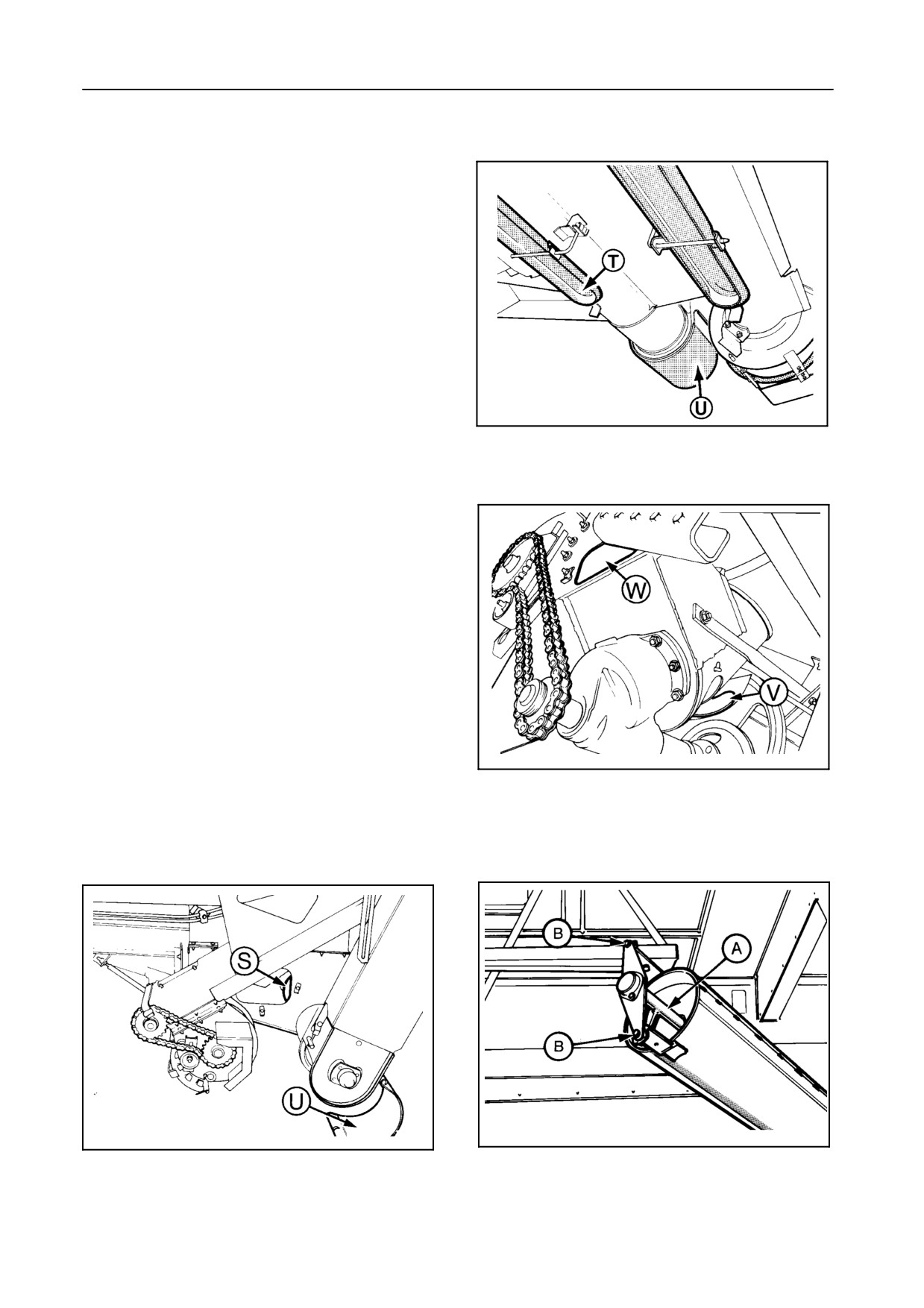
GRAIN TANK FILLING SYSTEM -- Figures 68 to 71
1.
The grain cross auger can be cleaned by removing
covers S and T.
2.
The grain elevator bottom side can be cleaned by
removing cover U.
3.
The grain elevator top side can be cleaned by re-
moving cover W.
42968
4.
In damp crop conditions (e.g. wet maize), it may
be necessary to regularly clean the passage be-
69
tween the grain elevator and the grain tank
bubble-up auger.
Access to this area can be obtained by removing
covers V and W.
5.
The grain tank bubble-up auger A can be easily re-
moved to clean it thoroughly.
Proceed as follows:
Remove two bolts and nuts B and remove the
bubble-up auger A.
When harvesting soya beans it is recom-
mended to perform this job every day.
43061
70
55148
43060
68
71
4-44
SECTION 4
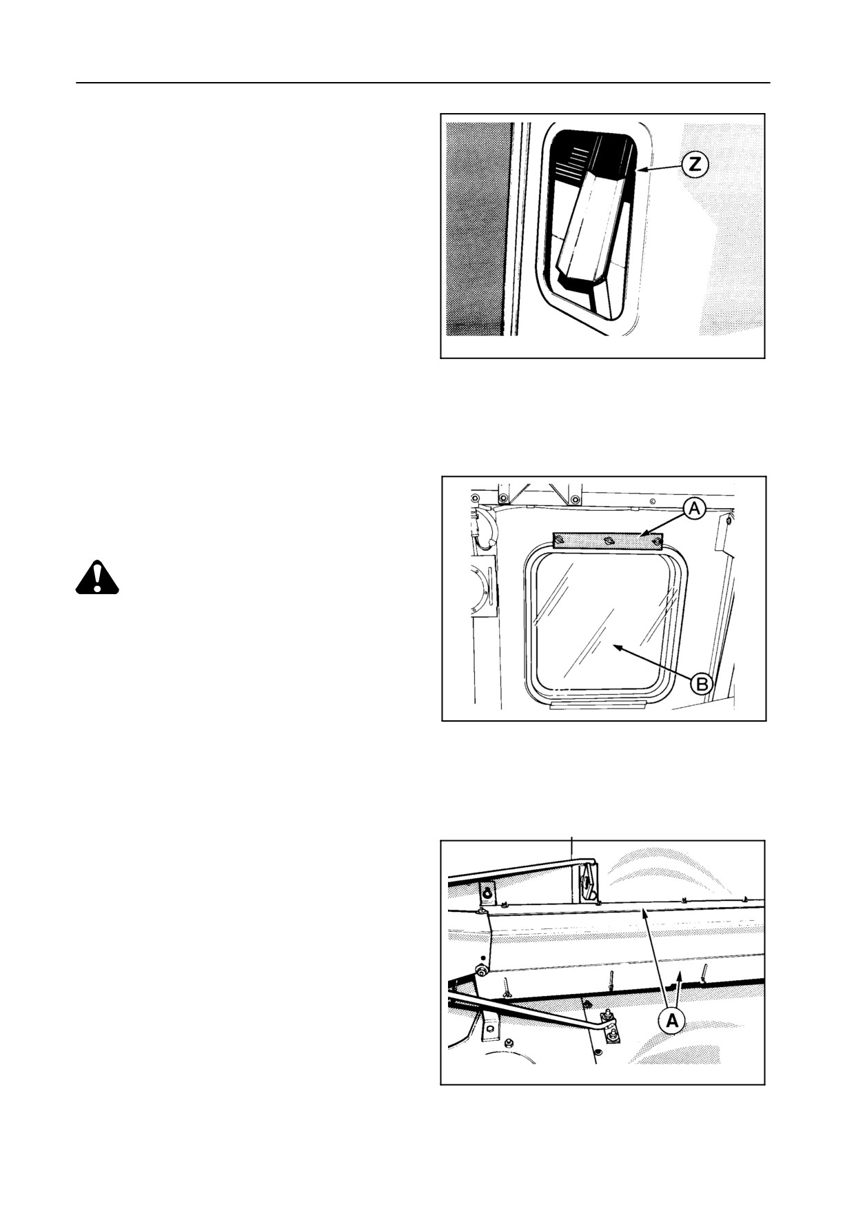
GRAIN SAMPLE ACCESS -- Figure 72
The grain tank is provided with an inspection window
Z where a grain sample can be taken when starting
off in the field. A channel section in the grain tank
brings the grain to the inspection window.
20989
72
GRAIN TANK WINDOW -- Figure 73
The window between the grain tank and the cab can
be cleaned as follows :
CAUTION:
Shut off the engine and remove the igni-
tion key before entering the grain tank.
1. Enter the grain tank at the rear over the engine
cover and remove strip A. See Section 2, page 25.
42939
73
2. Remove the grain tank window B to clean the area
between the cab window and the grain tank.
GRAIN TANK UNLOADING AUGER -- Figure 74
A cover plate is fitted over the grain tank unloading
auger. This cover plate is fitted with plates A which
can be adjusted to regulate the unloading rate accord-
ing to the nature and moisture content of the grain be-
ing handled.
Raise the plates to increase the unloading rate and
lower them to reduce it.
42939
74
4-45
FIELD OPERATION
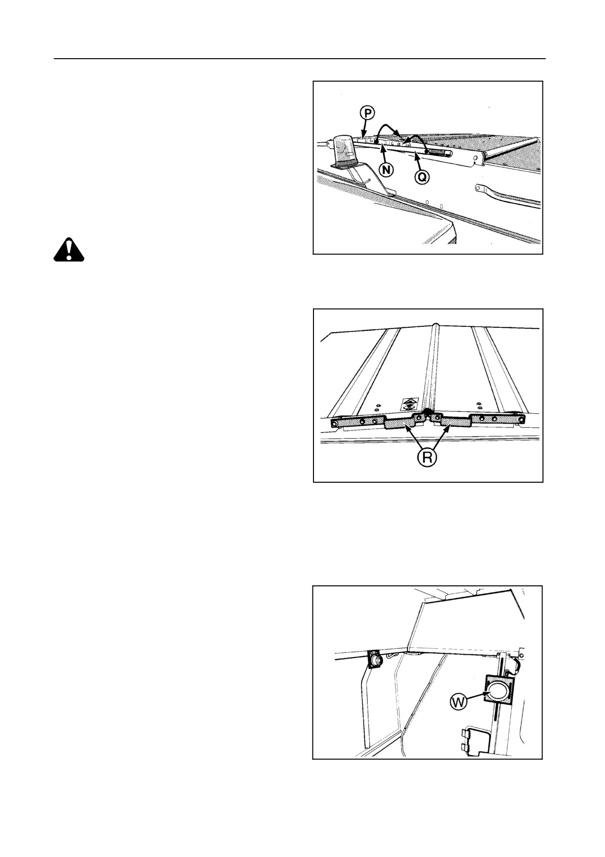
GRAIN TANK COVERS -- Figures 75 and 76
To open the covers, move the left-hand cover N as
indicated by the arrow.
Open the right-hand cover P using lever Q.
The covers can also be opened from the engine cover
platform using handles R.
30244
CAUTION:
75
S Do not step on the engine cover.
S Do not stand on the engine cover
when opening the grain tank.
42959
76
GRAIN TANK LEVEL SENSOR [if installed] --
Figures 77 to 80
Adjust sensor W, located in the grain tank, according
to the condition of the crop.
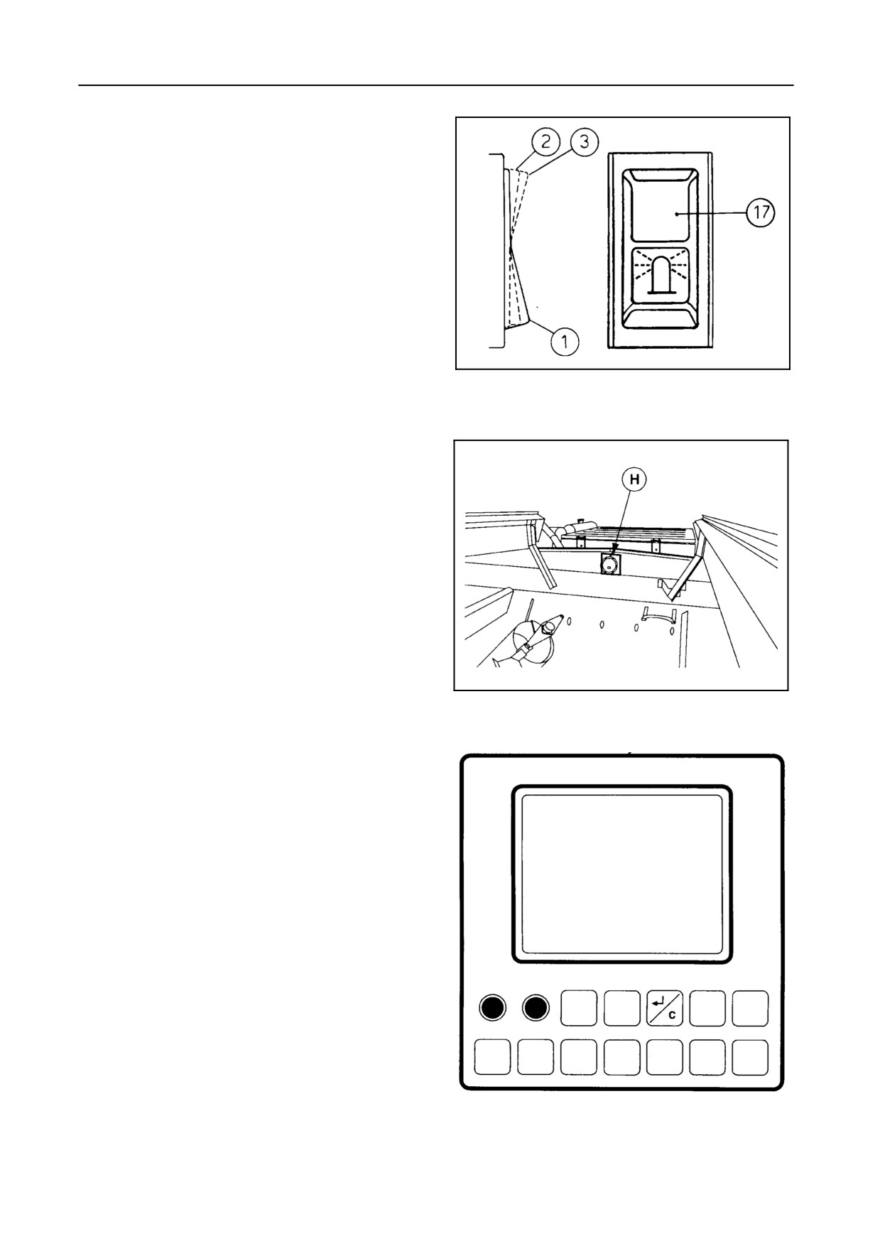
When the grain reaches the level sensor W, the fol-
lowing can be observed:
42957
77
4-46
SECTION 4
S The grain tank level warning light will illuminate.
S The audible signal will sound for 5 seconds.
S The flashing lights on the grain tank will be
switched on and
- will stop after 5 seconds when switch 17 is in
position 2, or
- will remain on when switch 17 is in position 3.
50394
78
When the grain reaches level sensor H, a message of
full grain tank appears on the InfoView monitor and an
audible alarm sounds for two seconds.
23286
79
GRAIN TANK FULL
52672
80
4-47
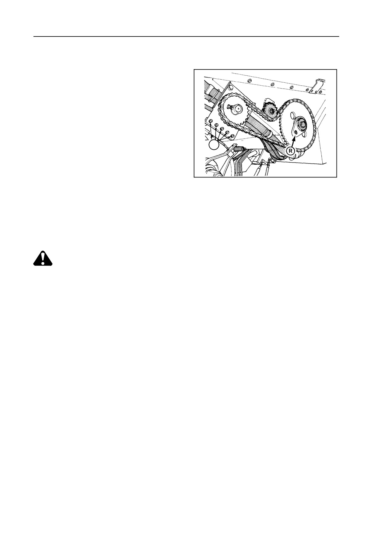
FIELD OPERATION
UNLOADING TUBE
A warning light is provided in the cab to alert the op-
erator when the unloading tube is not in the fully
closed position as this may be an operating hazard in
fields with trees, high tension wire pylons, telegraph
poles, etc.
SHEARBOLT ON THE UNLOADING SYSTEM
DRIVE -- Figure 81
S
The unloading system drive is protected by a shear-
bolt R.
42807
81
Spare shearbolts are located at S.
IMPORTANT:
S Tighten the bolt with a screwdriver holding
the nut with a wrench.
S Use only genuine shear bolts.
DANGER:
When opening the unloading tube or
driving with open unloading tube, ensure
that the tube cannot touch electric wires.
AUDIBLE ALARM
An audible signal (buzzer) is linked to the following
S Grain tank level indicator 100% (2 seconds)
elements:
(+ message on InfoView monitor)
S Direction indicators
S Excessive hydrostatic and hydraulic oil tempera-
ture sensor (+ warning light)
A separate audible signal (buzzer) is linked to:
NOTE:
If excessive oil temperature causes the alarm
S The rpm control monitor (5 seconds)
to function, try to locate the defect or contact
your dealer for assistance.
S The ‘‘error report’’ system of the Infoview monitor
(5 seconds)
S Handbrake (+ warning light)
S The straw walker protection (as long as the switch
of the straw walker protection is being pressed)
S Straw chopper guide plate (no warning light)
NOTE:
S Grain tank level indicator
70% (5 seconds)
When the alarm is functioning, try to locate the
(+ warning light)
defect or contact your dealer for assistance.
4-48
SECTION
4
AUTOMATIC ENGINE SHUT-OFF
In case of an emergency, in order to prevent engine or
hydrostatic system damage, or to protect your person-
al safety, the engine will automatically be shut off by
the following elements:
S Low engine oil pressure (+ warning light)
S Excessive engine oil and engine coolant tempera-
ture (+ warning light)
S Low hydrostatic oil pressure (+ warning light)
S Lowering the ladder to the engine platform in down
position
However, the engine can be started with the lad-
der in down position.
IMPORTANT:
Be aware that, if the engine is running with the
ladder in down position, the engine protection
system is not working.
INFOVIEW MONITOR
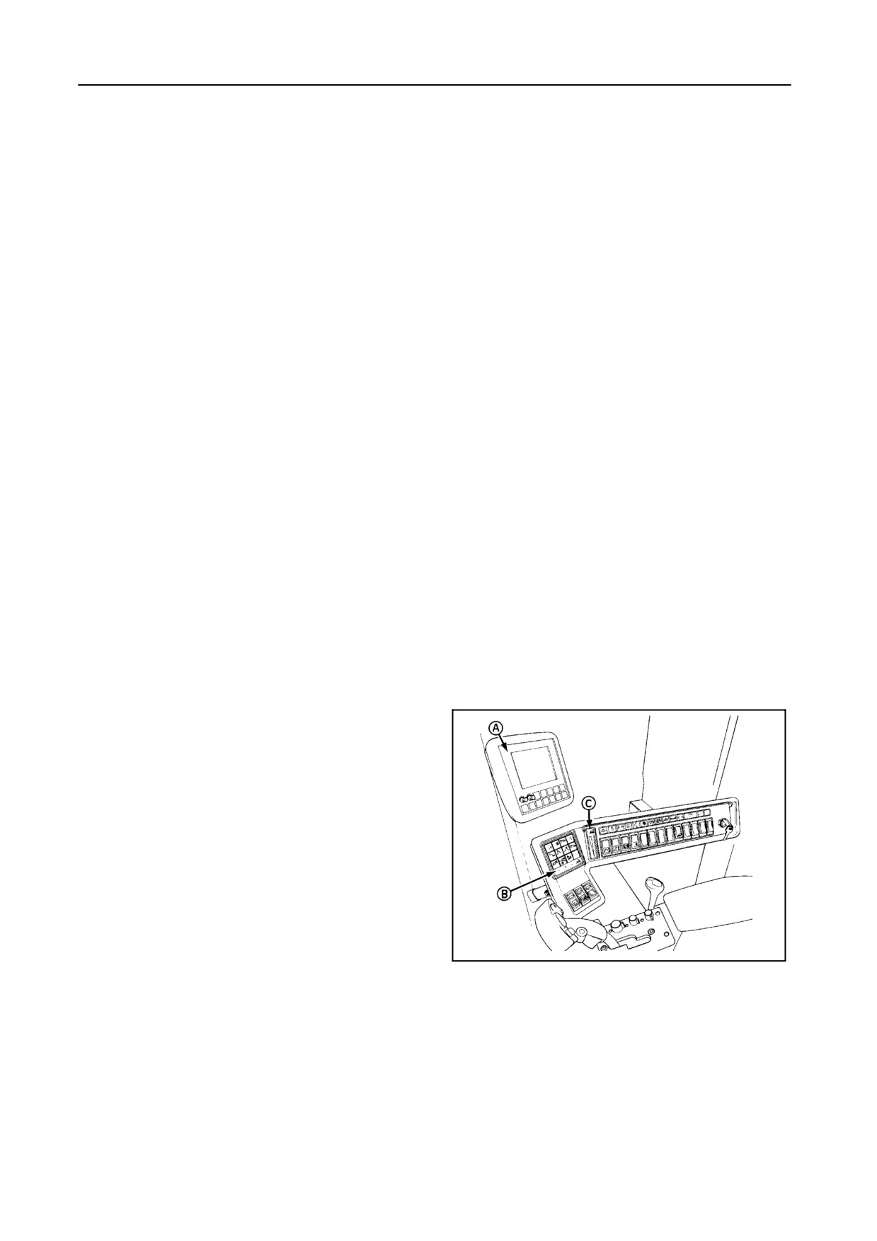
Refer to Figure 82
The combine is monitored in the cab by means of an
InfoView monitor A and led indicators B and C.
The monitoring on the InfoView monitor A, the lateral
float bargraph indicator B and the header height
bargraph indicator C are processed by electronics
which are located in the central electrical box near the
right-hand side of the cab.
51591
82
4-49
FIELD OPERATION
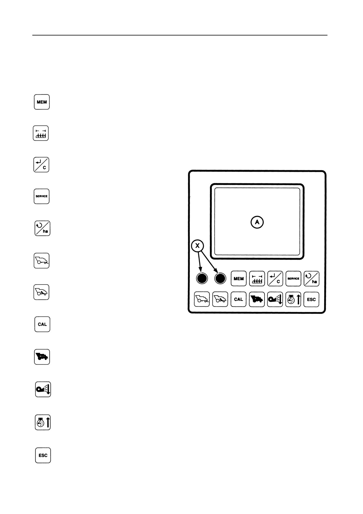
1 -- PANEL OVERVIEW -- Figure 83
A Display
X Performance bargraph adjusting knobs
Entry to Memory mode
Header width correction button
Enter/Clear button
Entry to Service mode
Button to switch from rpm mode to hec-
tare mode, or vice versa
Performance bargraph selector button
Returns bargraph selector button
48283
83
Entry to Calibration mode (see para-
graph headed ‘‘Calibration’’)
Ground speed selector button
Fan speed selector button
Scroll-down button
Engine speed read-out button
Scroll-up button
Escape button (from any mode to the
rpm mode, which is shown in Figure 83)
4-50
SECTION 4
2 -- OPERATION -- Figure 84
Through different modes, the InfoView monitor sup-
plies the following information:
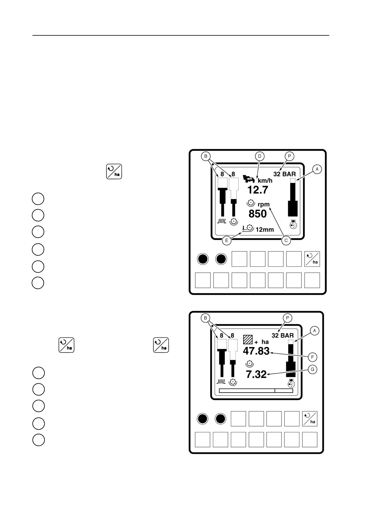
COMBINE OPERATION MODES
2.1
RPM mode -- Figure 84
This mode automatically appears when the ignition
key is turned on and can be selected from the area
counter mode by pressing
A Engine load bargraph
B Performance bargraph or returns capacity
C Threshing drum speed
D Ground, cleaning fan or engine speed
Concave clearance (not for models TX62-63)
E
P
Header cylinder pressure indication
52673
84
2.2
Area counter mode -- Figure 85
This mode can be selected from the rpm mode by
pressing
and can be left by pressing
A
Engine load bargraph
B Performance bargraph or returns capacity
F Area counter
G Threshing drum hours
Header cylinder pressure indication
P
52674
85
4-51
FIELD OPERATION
2.3
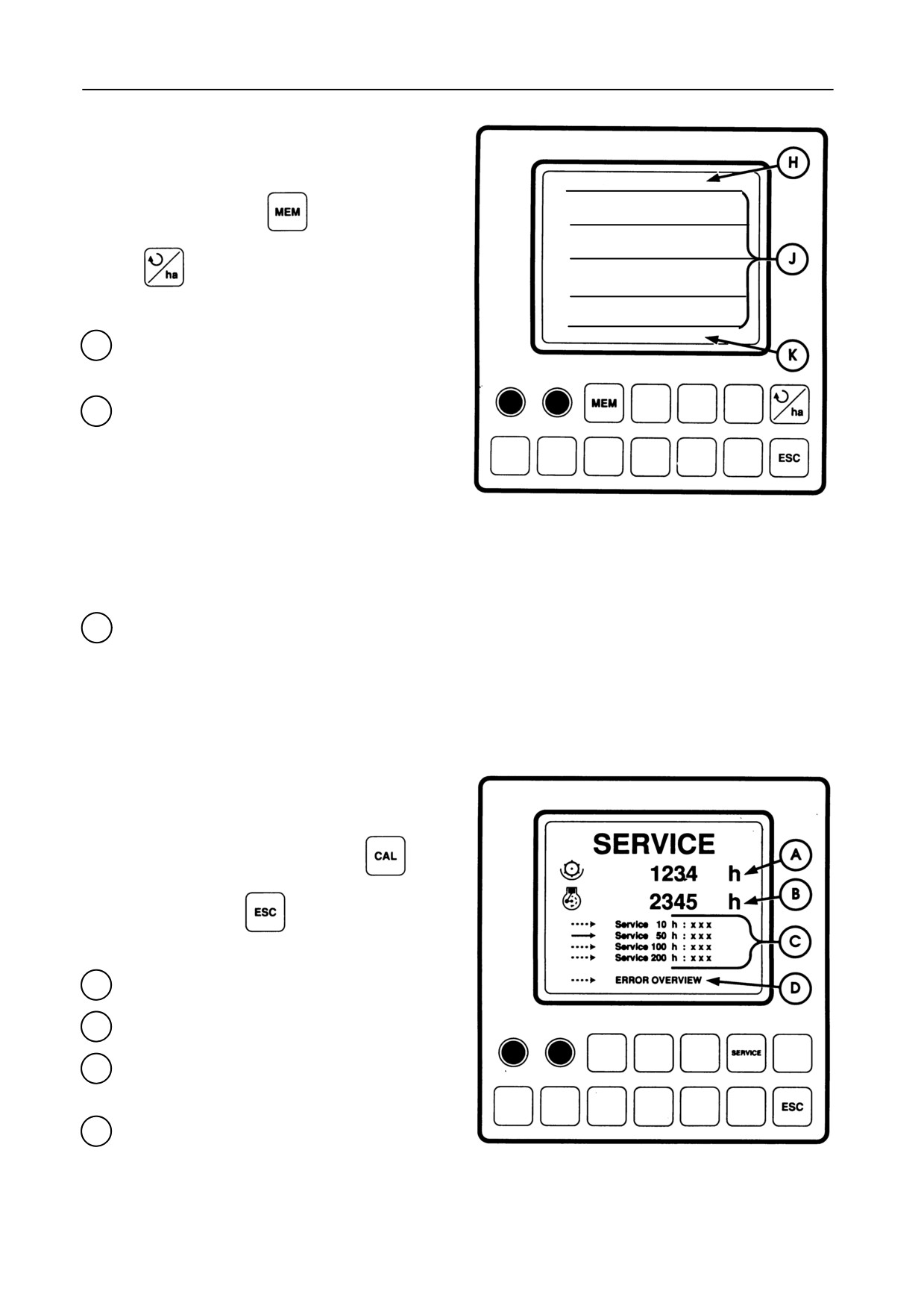
Memory mode -- Figure 86
This mode can be selected after selecting the area
WORK 88.88 ha 8888 h
counter mode by pressing
and can be left by
1 18 / NOV / 97
09.52
3.98 ha
1:01 h
3.87 ha/h
pressing
TOTAL 88.88 ha 8888 h
The latest threshed hectares and the latest
H
threshing hours since the latest storage of
results.
9
memories with separate results which
J
contain:
- Date and time of storage
52675
- Threshed area
86
- Threshing hours
- The average threshed area per hour
- RDS information [if installed]
Total threshed area and threshing hours of the
K
combine
2.4
Service mode -- Figure 87
This mode can be selected by pressing
and
can be left by pressing
A Total threshing hours
B Total engine hours
C The engine hours since the different services
have been performed and the hour indications
have been cleared
D
Access to the error overview
48287
87
4-52
SECTION 4
2.5
Error reporting system
The error reporting system is appearing in the rpm
mode as well as in the service mode.
The error reporting system is described further in this
paragraph.
2.6
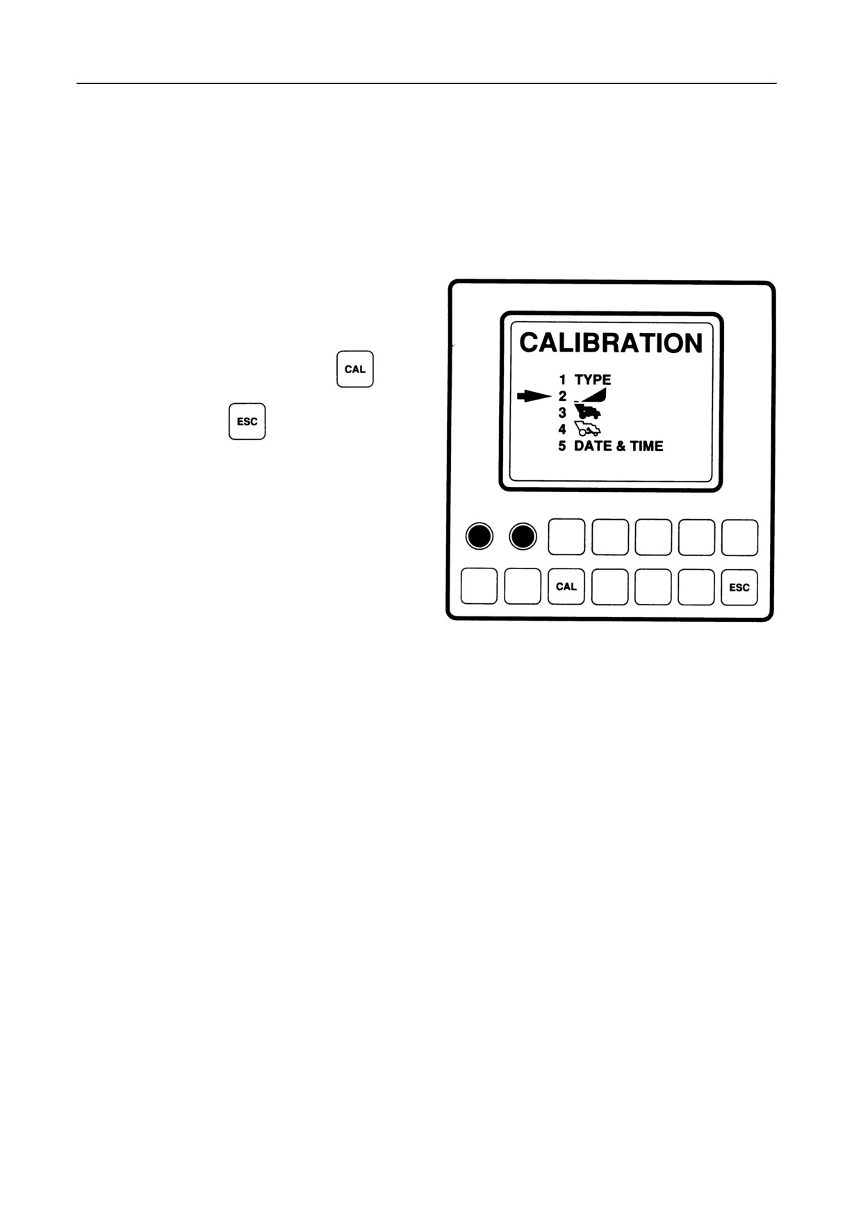
Calibration mode -- Figure 88
This mode can be selected by pressing
and
can be left by pressing
Combine configuration input to ensure a correct set-
up of the central process unit.
The different modes can be selected using the touch-
sensitive keys which are located underneath the dis-
play.
48288
88
3 -- RPM MODE
The rpm mode is used during field operation or road
transport.
NOTE:
As soon as the power is switched on by turning
the ignition key, the InfoView monitor will auto-
matically go through a self-diagnostic error re-
porting system.
If the monitor reports an error, refer to the para-
graph headed ‘‘Error Summary’’, paragraph
5.2. in this Section.
If no errors are detected, the monitor will enter
the combine operation mode.
4-53
FIELD OPERATION
With the rpm mode selected, the following information
will be provided:
3.1
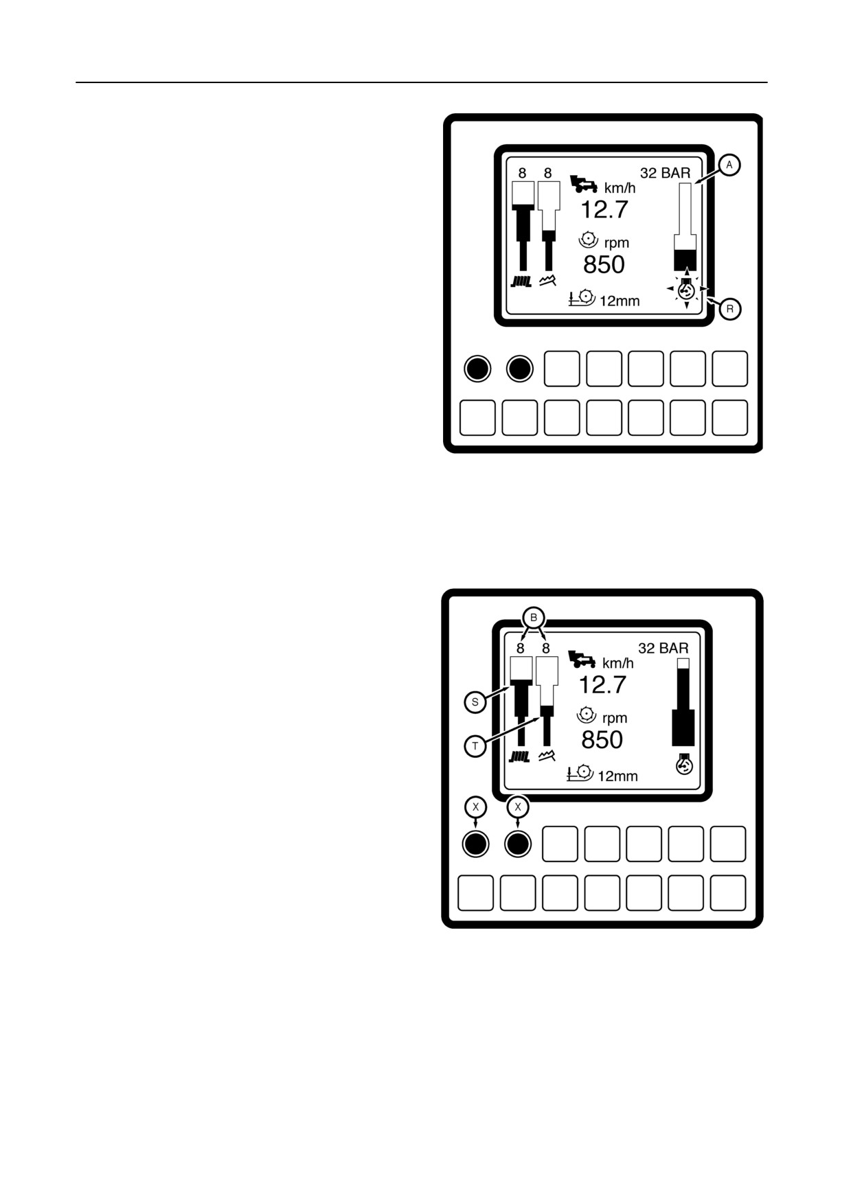
Engine load bargraph A -- Figure 89
The bargraph segments light up proportionally to the
measured engine speed. All segments light up with
the engine at maximum speed (without load).
Maximum engine speed minus 5%:
Engine bargraph lower segment and symbol R start to
blink.
Maximum engine speed minus 10%:
54770
Engine symbol R blinks and bargraph is empty.
89
3.2
Performance bargraph B -- Figure 90
Two bargraphs are provided for displaying the sieves
S and straw walker T losses.
The bargraph segments light up proportionally to the
losses and to the potentiometer X setting (sensitivity).
The potentiometer setting is displayed from 1 to 10
above the bargraphs: the higher the number, the high-
er the sensitivity.
To set the combine performance monitor, proceed as
follows:
54771
1. Engage the threshing and the header drive.
90
2. Engage the first or second gear and enter the
crop.
3. Adjust the reel height, the reel fore and aft setting
and the reel speed, according to the type of crop
being harvested.
4-54
SECTION
4
4. Adjust the ground speed with the ground speed
control lever. The ground speed in km/h can be
observed on the InfoView monitor.
5. Stop the machine after a hundred metres and
take a grain sample. Check also for grain losses
in the swath. If the result is unsatisfactory, carry
out the necessary adjustments.
Also refer to paragraph headed ‘‘Combine perfor-
mance checks’’ further in this Section.
The setting of the combine performance monitor
has to be performed or at least checked whenever
changing from field or crop.
6. Select the highest ground speed consistent with
obtaining good results.
7. Set the left-hand sensitivity knob X of the sieves
sensor so that all segments on the sieve bargraph
lower step illuminate.
8. Set the right-hand sensitivity knob X of the straw
walker sensor so that all segments of the straw
walker bargraph lower step illuminate.
9. Increase the ground speed until one of the bars
glows into the upper step.
10. Stop the machine and check if the grain loss has
clearly increased. If not, this means that the sen-
sitivity of the bar with the most segments on, was
set too high. Set the sensitivity knob correspond-
ing with this bar so that it glows on a lower level at
the speed selected under point 6. If the rate of
loss increases, more segments will appear. If the
rate decreases, segments will extinguish.
4-55
FIELD OPERATION
3.3
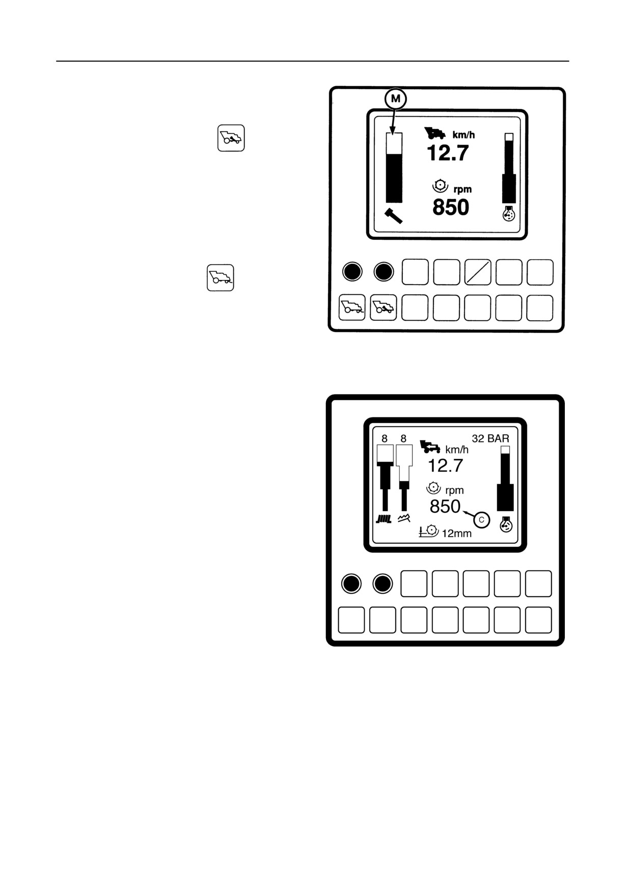
Returns capacity bargraph M -- Figure 91
The performance bargraphs B are replaced by a re-
turns capacity bargraph M when
is pressed
for:
S Less than 3 seconds: The returns are dis-
played for 5 seconds. After that, the perform-
ance bargraphs are again displayed.
S More than 3 seconds: The returns are dis-
played until the performance bargraphs are se-
lected again by pushing
52693
91
3.4
Threshing drum speed C -- Figure 92
Thiscountershowsthecurrentdrumspeedwhichcan
be changed with the drum speed rocker switch.
54772
92
4-56
SECTION
4
3.5
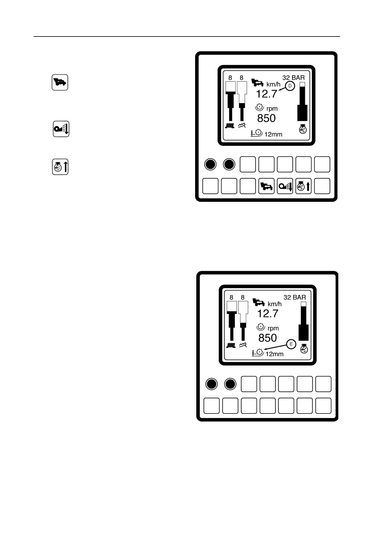
Ground, cleaning fan or engine speed D --
Figure 93
Press
to display the ground speed which is ad-
justabe with the ground speed control lever and the
gearshift lever.
Press
to display the cleaning fan speed wich
is abjustable with the cleaning fan rocker switch.
Press
to display the engine speed. Adjust with
the engine speed rocker switch.
52693
When starting up the InfoView monitor, the ground
93
speed will be displayed.
The ground speed will automatically be displayed
when the combine ground speed is higher than 20
km/h for a period of 20 seconds.
3.6
Concave clearance E -- Figure 94
ThecurrentconcaveclearanceEisshownandcanbe
adjusted with the concave clearance rocker switch
(from 3 to 51 mm).
54774
94
4-57

FIELD OPERATION
4 -- AREA COUNTER MODE -- Figure 95
The area counter mode as well as the rpm mode is
used during field operation to control the different
combining parameters described below.
NOTE:
In the area counter mode the engine load bar-
graph A and the performance bargraph B (or
returns capacity bargraph) are displayed as
well.
Refer to paragraphs 3.1 to 3.3.
Press
to switch from rpm to area counter
mode, or vice versa.
54775
95
4.1
Threshing drum hours F -- Figure 96
This counter shows the time the threshing
mechanism has been engaged since the area counter
mode was last cleared
(Refer to paragraph
5
‘‘Memory Mode’’.
54776
96
4-58
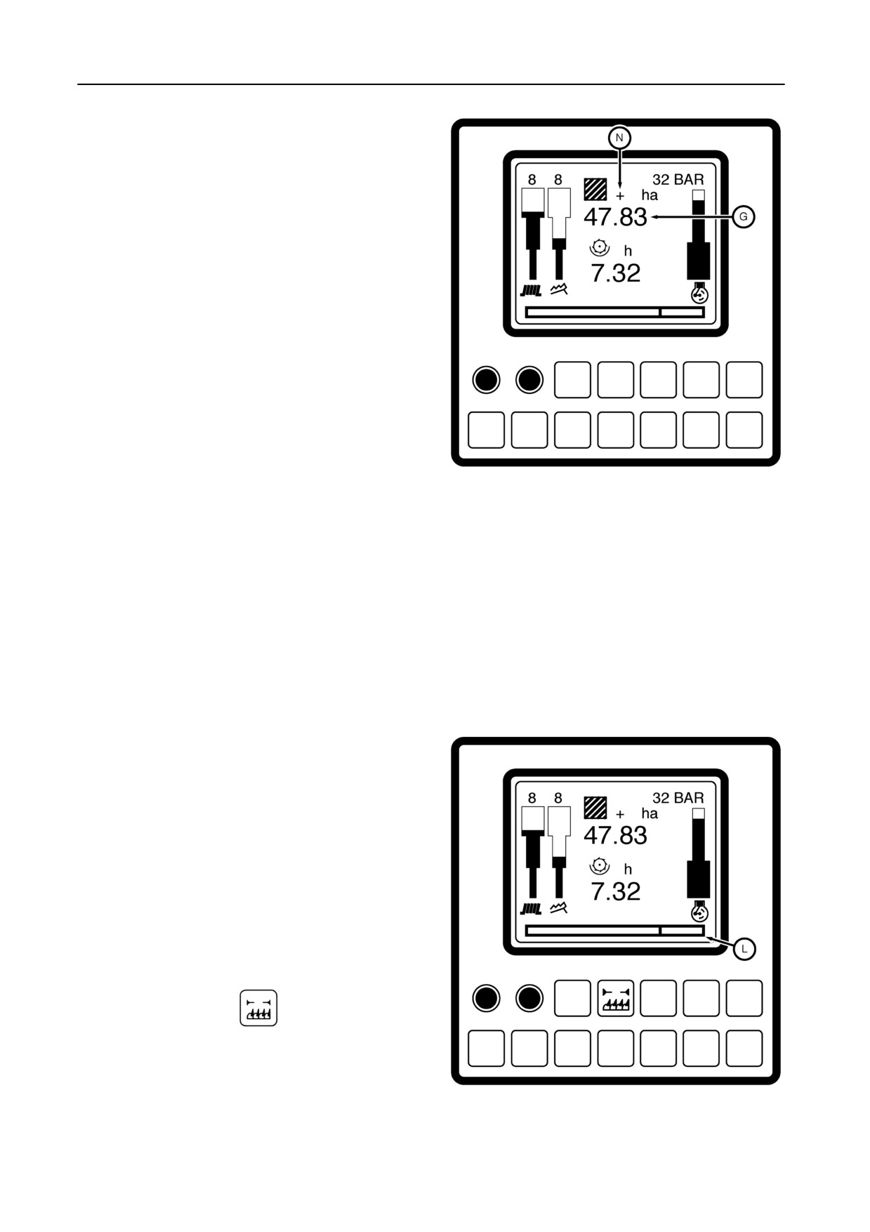
SECTION
4
4.2
Area count G -- Figure 97
This counter shows the area which has been har-
vested since the area counter mode was last cleared
(Refer to paragraph 5 ‘‘Memory mode’’).
The area counter starts counting when:
S The threshing mechanism is engaged,
and
S The header drive is engaged,
and
S The header height is below the height cal-
ibration value (refer to paragraph ‘‘Cal-
ibration’’, subheading 2.6).
54777
97
The monitor will display a ‘‘+’’ symbol N when the area
counter is operating.
IMPORTANT:
The area counter only gives an approximate val-
ue. The accuracy depends on correct calibration
of all parameters (wheel size, header type, ...)
but also on the real cutting width. Never switch
off the battery before switching off the ignition
(with the key). This will avoid the risk of losing the
latest information on area counting.
4.3
Bottom text line L -- Figure 98
With the area counter mode selected, the text line pro-
vides the following information:
a) Header width correction (only when the threshing
and header mechanisms are engaged).
S If the full header width is not used during har-
vesting, an area counter correction has to be
made by pressing
Each pulse (with audible signal) reduces the
header width by one quarter. In case a maize
54778
header is fitted, each pulse reduces the header
width with one row unit).
98
4-59
FIELD OPERATION
S Each time the area counter is stopped by rais-
ing the header above the height calibration
value (refer to paragraph ‘‘Calibration’’, line 2,
d), the full header width is restored.
S The header width correction is also possible
and is shown in the rpm mode.
b)
Instant area capacity (ha/hour)
The average of the last 5 seconds counted area
capacity is displayed if the ‘‘+’’ symbol appears on
the screen.
or,
c)
Average area capacity (ha/hour)
The average area capacity since the area counter
was last cleared (refer to paragraph ‘‘Memory
mode’’, subheading 5.1) is displayed if no ‘‘+’’ sym-
bol appears.
d)
Distance (km)
The accumulated distance travelled since the
monitor was last cleared is displayed by pressing
5 -- MEMORY MODE
Nine area counting results can be stored in the moni-
tor memory.
5.1
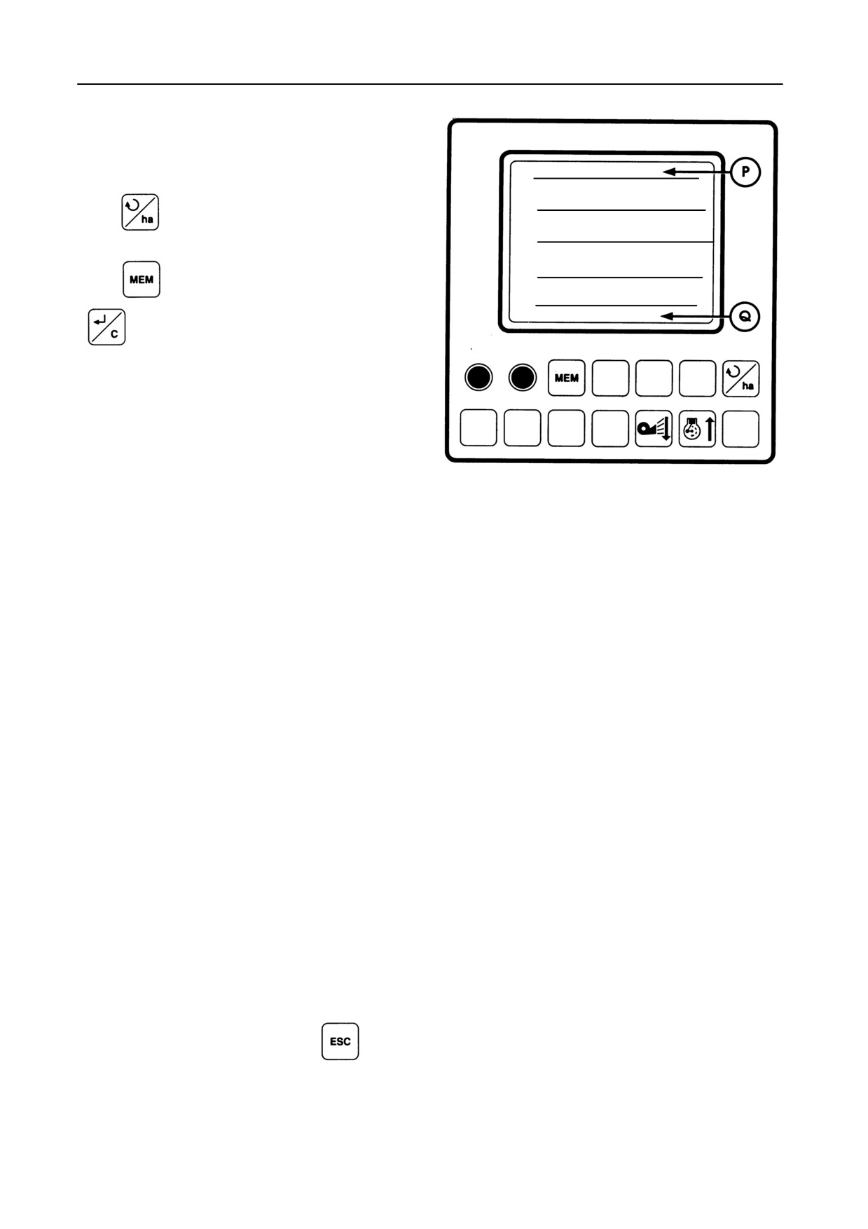
Memorizing area counter results -- Figure 99
Memory screen top line P
Drum hours and area values of the latest area counter
result before memorizing.
After memorizing, the values turn to zero.
4-60
SECTION 4
To memorize current area counter values, the area
counter mode should be selected, with the ground
speed at ZERO.
WORK 88.88 ha 8888 h
1 18 / NOV / 97
09.52
Press
to open the area counter mode
3.98 ha
1:01 h
3.87 ha/h
Press
to open the memory screen and
TOTAL 88.88 ha 8888 h
to memorize.
All current area counter values (area, drum hours,
area capacity, date and time) will then be stored in
memory 1.
52676
All other memorized results will then shift one memory
99
towards memory 9.
When all memories are occupied, the message
‘‘Memories Full’’, alternated with the message ‘‘Clear
Memory’’ , appears on the bottom text line and an
audible signal is generated. In this situation a new
area counter result cannot be memorized.
To clear memories, refer to subheadings 5.2 and 5.3.
REMARK:
Area and drum hours values of ZERO cannot
be memorized.
Memory screen bottom line Q
Total area and drum hours values.
These values are instrument life time totals and can-
not be cleared.
Leave the memory mode by pressing
The display automatically returns to the area counter
mode.
4-61
FIELD OPERATION
5.2
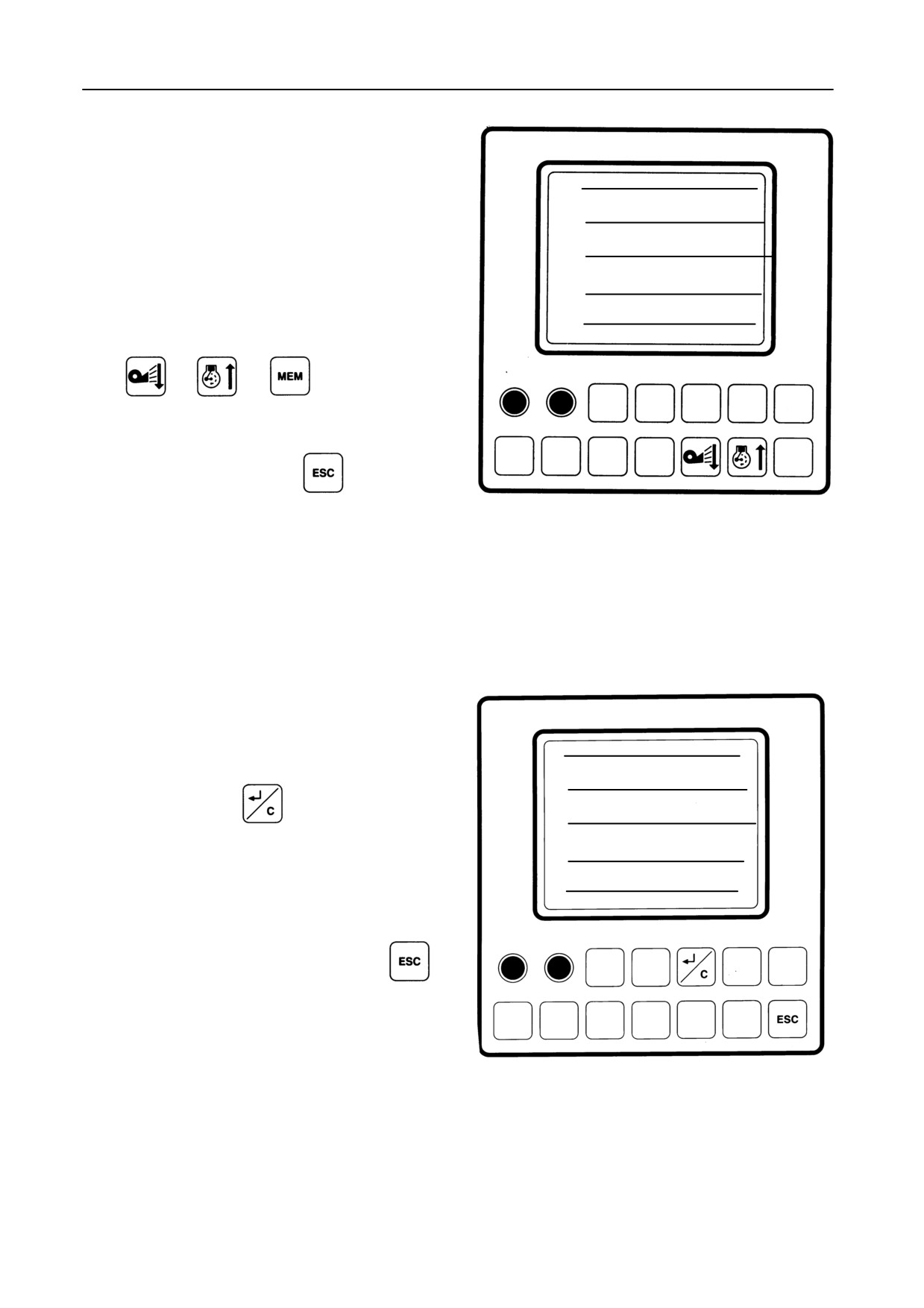
Selecting memory values -- Figure 100
On the memory screen, a memory can be selected to
WORK 88.88 ha 8888 h
display more information, such as:
1 18 / NOV / 97
09.52
S Memory reference
:
1
3.98 ha
1:01 h
3.87 ha/h
S Area
:
3.98 ha
S Threshing drum hours
:
1.01 h
S Area capacity (ha/hour)
:
3.87 ha/h
S Date and time
18 Nov 97 09.52
TOTAL 88.88 ha 8888 h
Press
or
or
to select a mem-
ory, which will pop up on the screen.
Leave the memory by pressing
52677
100
The display automatically returns to the area counter
mode.
5.3
Clearing memories -- Figure 101
WORK 88.88 ha 8888 h
A selected memory (refer to subheading 5.2) can be
1
18 / NOV / 97
09.52
cleared by pressing
to bring the selected
3.98 ha
1:01 h
3.87 ha/h
memory values to ZERO. This action can be repeated
for each memory, except for memory 1.
All memories which are brought to ZERO are cleared
TOTAL 88.88 ha 8888 h
when leaving the memory mode by pressing
The display automatically returns to the area counter
mode.
52678
101
4-62
SECTION 4
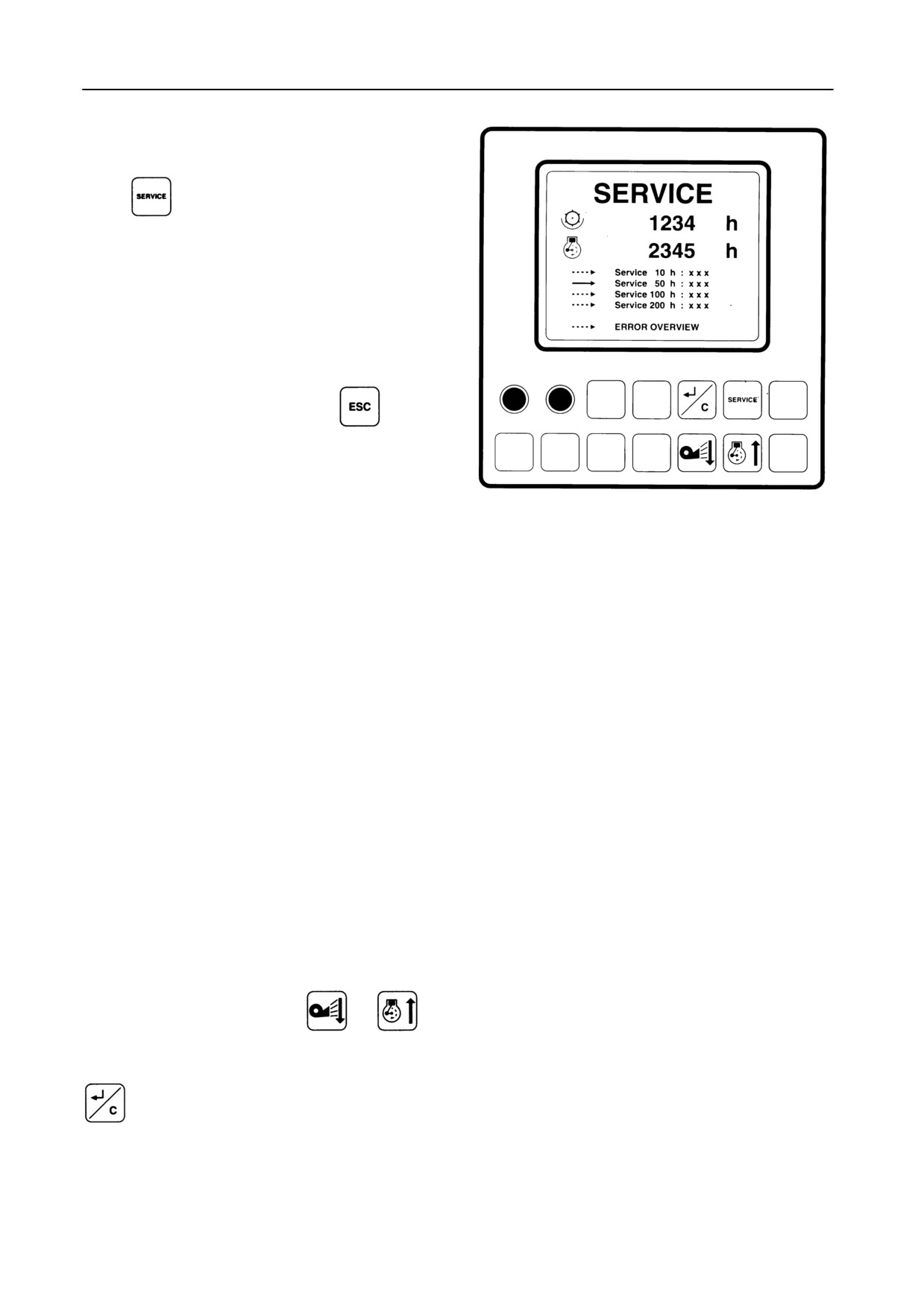
6 -- SERVICE MODE -- Figure 102
Press
to enter the service mode, which will
display:
S Total threshing drum hours
S Total engine hours
S Engine hours service intervals
S Error view selector line
Leave the service mode by pressing
48172
102
6.1
Service intervals
The service intervals are displayed as follows:
S Service 10 h : W
S Service 50 h : X
S Service 100 h : Y
S Service 200 h : Z
W, X, Y and Z are counted engine hours. These val-
ues start to blink if the service interval is exceeded.
After servicing the combine, the related service inter-
val has to be reset.
To reset a service interval, press
or
to
select the desired service interval (marked by an ar-
row next to the service interval) and then press
to reset. This command returns the engine
hours value of the related service interval to ZERO.
4-63
FIELD OPERATION
6.2
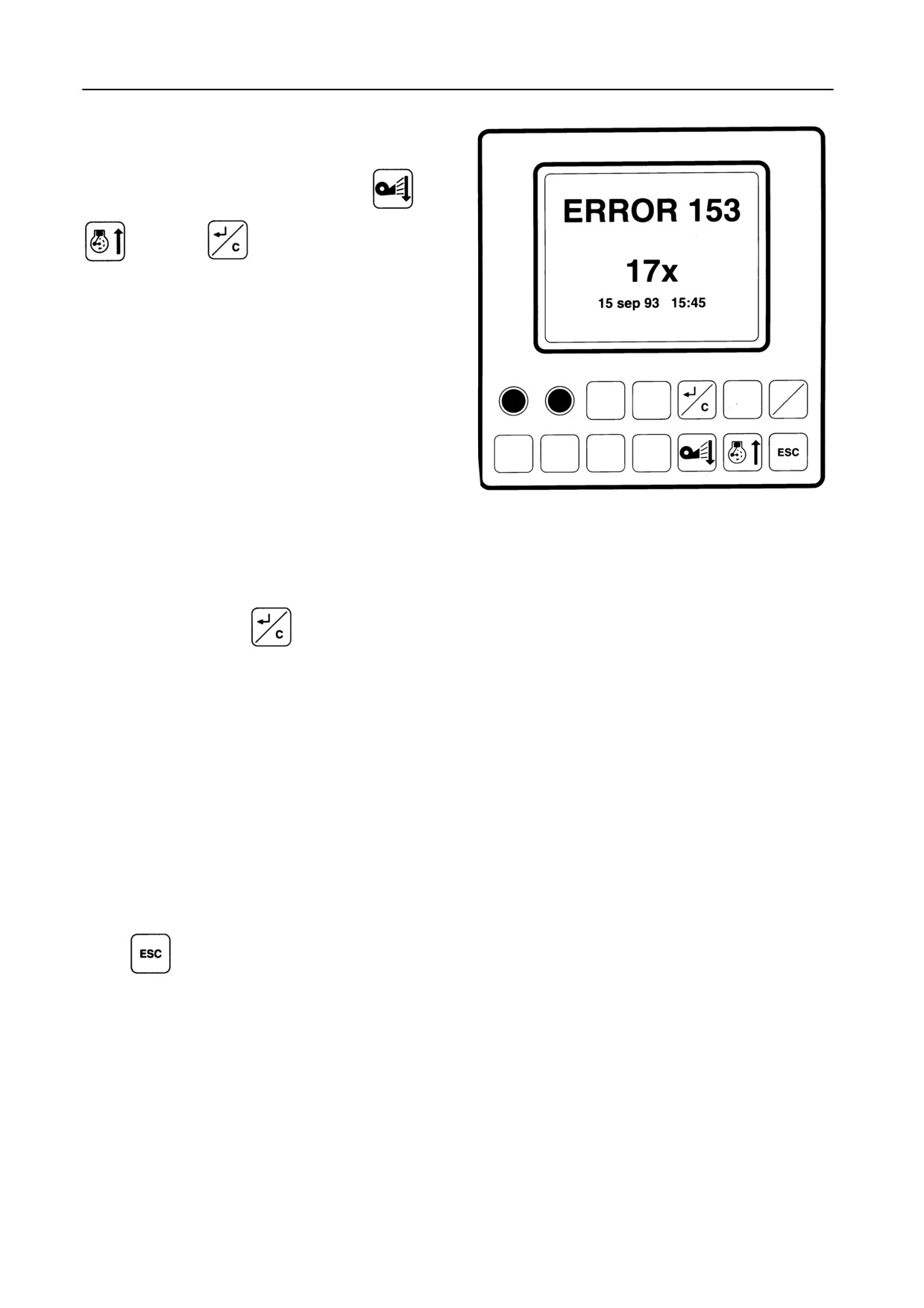
Error summary -- Figure 103
Select the error summary by pressing
or
, and then
to confirm.
The error reporting system provides the following in-
formation:
S
Error code:
1 up to 99 : high importance level
100 up to 499 : medium importance level
500 up to 999 : low importance level
IMPORTANT:
Error 171 is not an error but a real time voltage
48173
measurement.
103
S
Error frequency:
The error counter indicates the frequency of the
related error.
After the error has been corrected, reset the
counter, by pressing
This will delete the error from the error summary.
S
Error date and time of first occurrence.
S
Error description.
The error reporting system informs the user in dif-
ferent ways:
-- All errors that can be detected when the igni-
tion key is in the ON position, before starting
the engine, are displayed at that moment.
These error reports can be cleared by pressing
or by starting the engine.
-- After starting the engine, the errors with high or
medium importance levels are displayed
whenever they occur (linked to an audible
alarm).
The high priority errors are displayed con-
tinuously as long as the error exists, because
the system cannot function as long as the error
exists.
4-64