New Holland TX62, TX63, TX64 Plus, TX65 Plus, TX66, TX67, TX68, TX68 Plus. Operator's Manual - page 2
SECTION
2
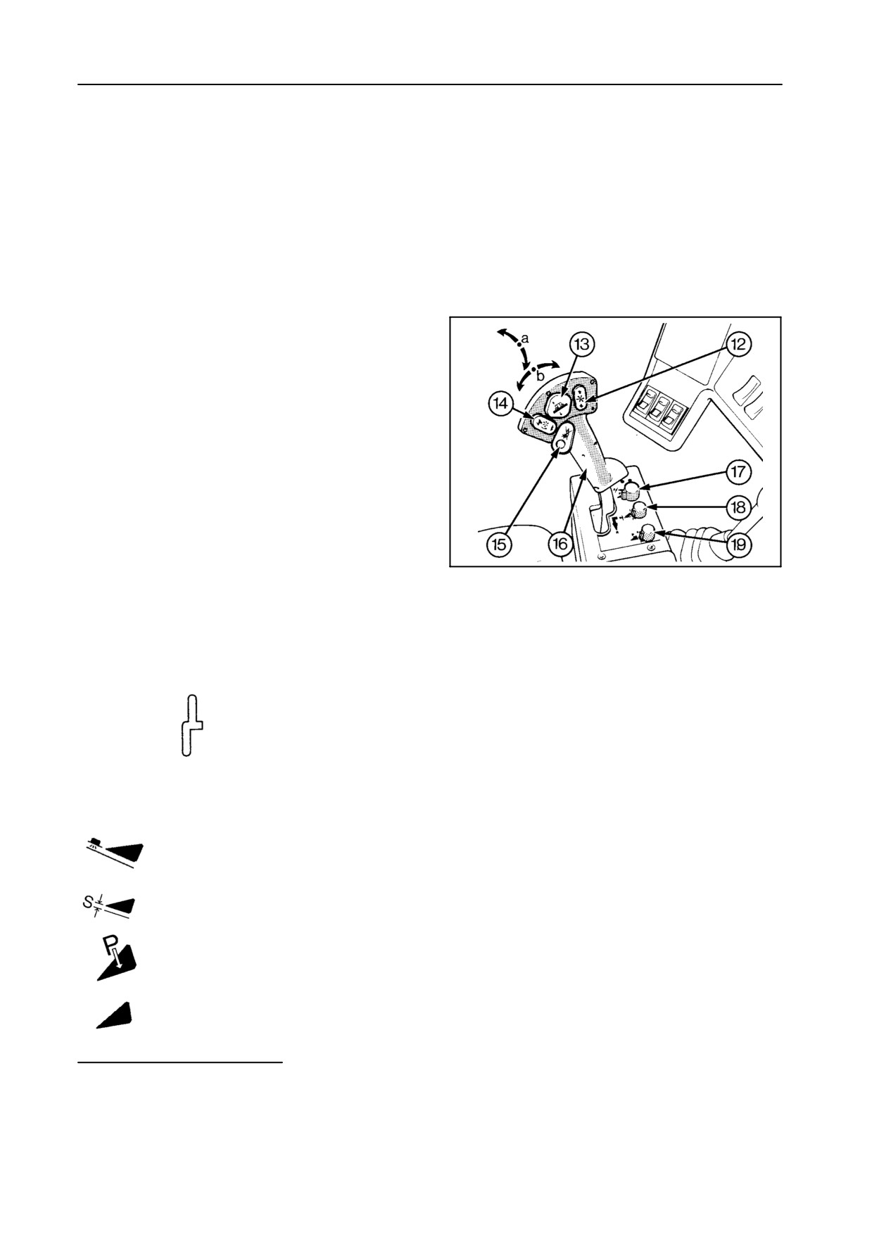
ARM REST MODULE -- Figures 7 to 9
12
Reel height control rocker switch
13
-a
2-speed header height control rocker switch
-b Header lateral flotation control rocker switch
up
= header up
down
= header down
left
= header tilting to left-hand side
right
= header tilting to right-hand side
14
- Reel variator rocker switch
up
= speed increase
down
= speed slowdown
- Header and straw elevator reversing rocking
control (if used in combination with 21)(1)
15
Header drive and unloading auger quick stop
(one-pulse button)(1)
Use this quick stop to avoid crop blockage or
42765
combine damage.
7
TX62-63-64
PLUS-65PLUS-66-68-68PLUS
One pulse on the quick stop button will stop the
header and unloading auger drive.
16
Ground speed control lever
Forward
Neutral
Rearward (+ audible alarm)
17
Header control selector switch(2)
Stubble height and autofloat operation
Stubble height operation only
Compensation operation
Transport position
(1) Not applicable for models TX62-63
(2) Not applicable for model TX62 without
automatic header compensation
2-7
OPERATION
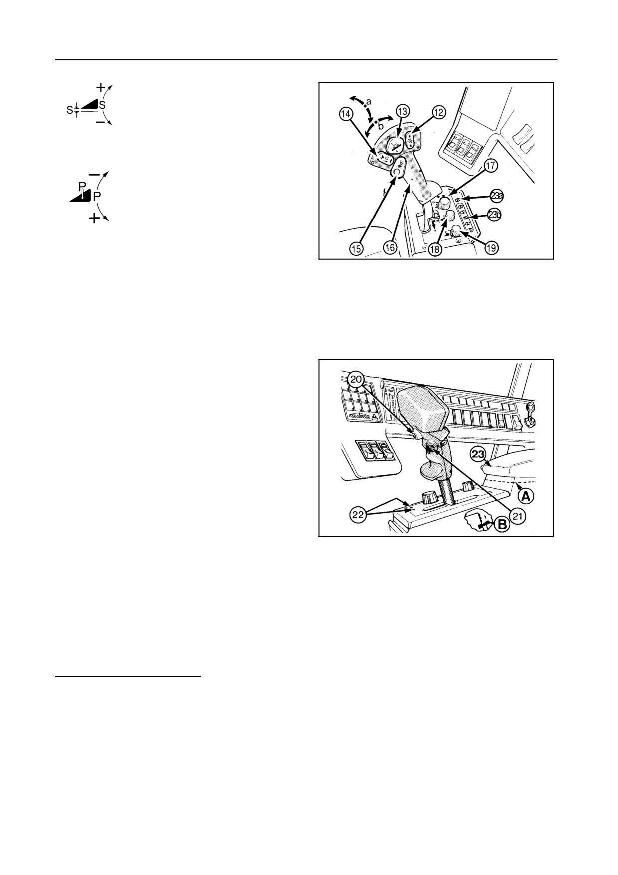
18
Header stubble height control knob(2)
19
Header compensation control knob(2)
42765
20
Automatic header height control switch(2)
8
TX67
21
Header and straw elevator reversing button(1)
22
Header compensation autodiagnostic control
indicators(2) (refer to Section 4 - FIELD OP-
ERATION)
23
Arm rest cover: Access to emergency switch
when ground speed control fails. Remove plate
A and push the rocker switch B up to move the
machine forwards, push the rocker switch B
down to move the machine rearwards (switch is
always operative).
23a
Remote emergency and parking brake button
(symbol P) [model TX67 only]
42759
9
23b
Remote gearshift panel (model TX67 only)
(1) Not applicable for models TX62--63
(2) Not applicable for model TX62 without automatic
header compensation
2-8
SECTION 2
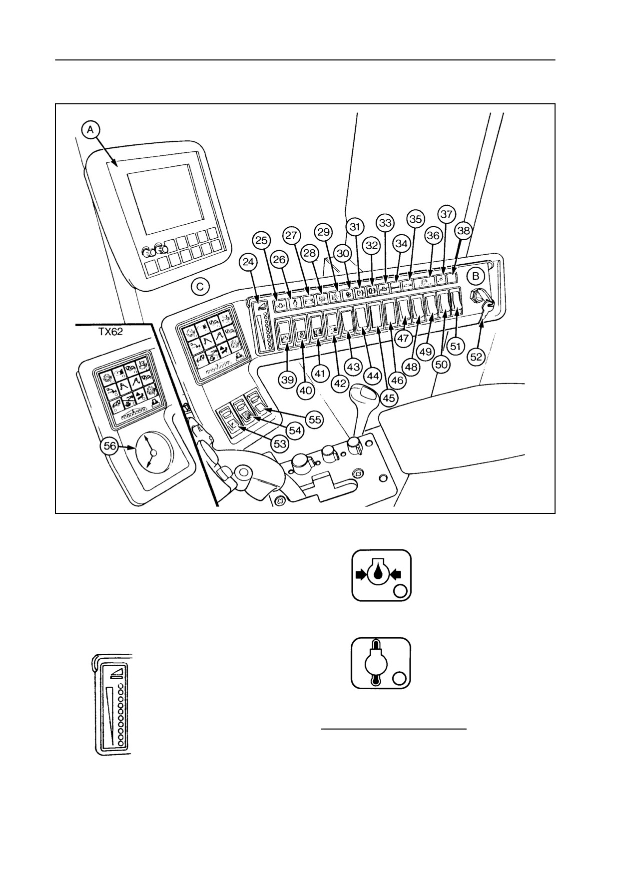
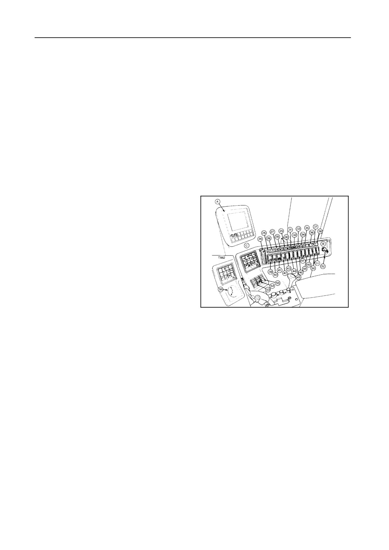
INSTRUMENT PANEL -- Figure 10
42763
10
A InfoView monitor (refer to Section 4 -- FIELD
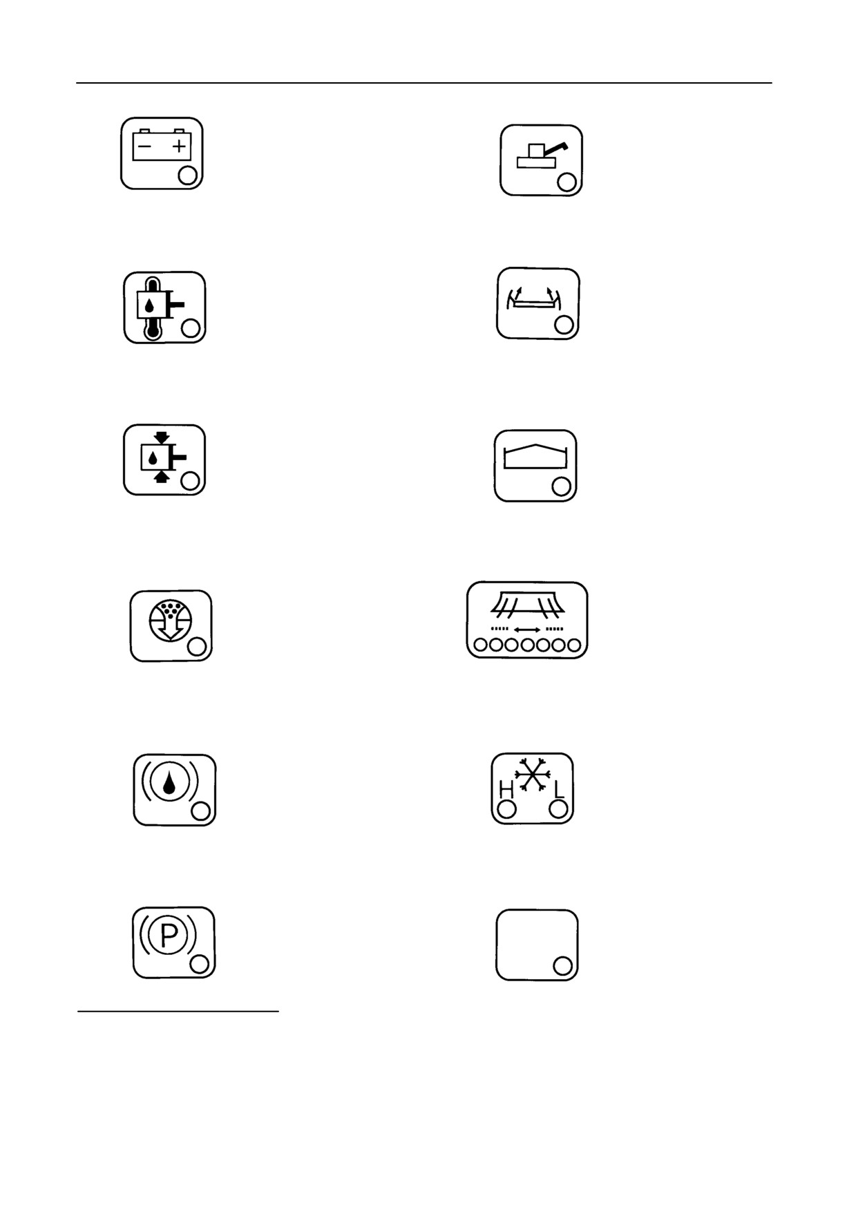
25
Low engine oil pressure
OPERATION)
warning light(*)
B General module
26
Excessive engine oil and
engine coolant tempera-
24
Stubble height indica-
ture warning light(*)
tion. The minimum and
maximum indication cor-
responds with the se-
lected minimum and
maximum stubble height
(refer to Section
4
--
(*) NOTE:
FIELD OPERATION,
Warning lights 25, 26 and 29 will automatically shut
off the engine to prevent damage of the engine or the
paragraph
1.6
Calibra-
hydrostatic system.
tion).
2-9
OPERATION
27
Battery no-charge warn-
33
Open unloading tube
ing light
warning light
28
Excessive hydrostatic and
34
Self-levelling
cleaning
hydraulic oil temperature
system warning light
warning light
(linked up
(lights up when system
with buzzer)
does not work properly)
29
Low hydrostatic oil pres-
35
Full grain tank level
sure warning light (*)
warning light (linked up
with buzzer)
Straw chopper deflector
30
Engine air filter obstruc-
36
plates position indication
tion warning light
(only when deflector
electrical control is in-
stalled)
31
Brake linings replacement
37
Air conditioning high and
and low brake fluid level
low pressure warning
warning light
lights
32
Parking brake ‘‘ON’’ warn-
38
Not used
ing light
(linked up with
buzzer)
(*) NOTE:
Warning lights 25, 26 and 29 will automatically shut off
the engine to prevent damage of the engine or the hy-
drostatic system.
2-10
SECTION 2
39
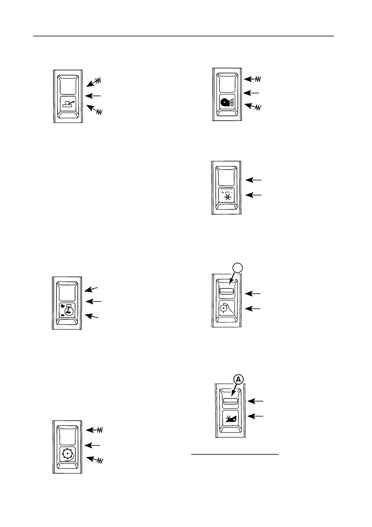
Unloading tube swing
42
Cleaning fan speed rocker
rocker switch
switch
Swing in position
+
Neutral
Neutral
Swing out position
--
OPERATION:
43
Reel speed synchroniza-
Threshing mechanism NOT ENGAGED:
tion tumbler switch
Press the switch two times and keep it depressed
the third time to swing the unloading tube out or in.
OFF
Threshing mechanism ENGAGED:
ON
Press the switch to swing the unloading tube out or
in.
Press the opposite part of the switch to stop the
movement.
44
Straw chopper engage-
40
Engine throttle control
rocker switch (with centre
ment tumbler switch
A
position)
+
OFF
Neutral
ON(1)
--
NOTE:
The engine rpm can only be increased mini-
45
Models TX62-63 only
mum 5 seconds after starting the engine.
Header and straw elevator
reversing switch
41
Threshing drum speed
OFF
rocker switch
ON
+
Neutral
--
(1)
To unlock, pull the spring-loaded lock A down and
press the lower part of the switch.
2-11
OPERATION
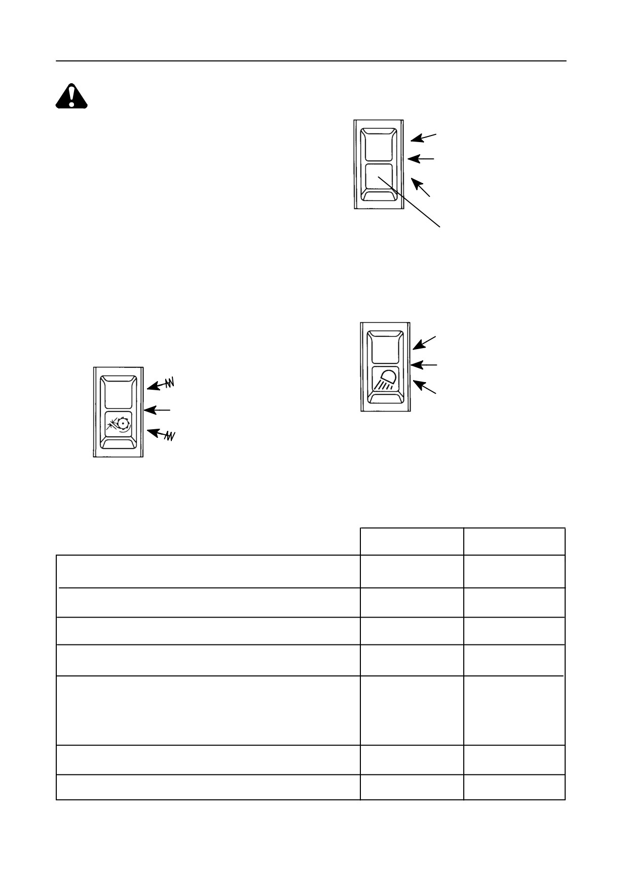
46
Header vertical knife tum-
bler switch [if installed]
WARNING:
S
Model TX62
When the ignition key is switched on,
OFF
it is possible to reverse the straw ele-
vator operation without the engine
Vertical right-hand knife
running (electrical motor).
D
ON
S
Model TX63
Both vertical knives ON
Ensure the header and straw elevator
reversing switch is in the OFF position
(red plastic window)
when starting the combine, otherwise
the straw elevator would start revers-
ing immediately after starting the
combine.
47
Operating lights tumbler
45
Models TX64PLUS-65PLUS-
switch
66-67-68-68PLUS
Drum concave control
rocker switch
OFF
(a)
close angle
+ (open) = lower concave
(b)
far angle
Neutral
-- (close) = lift concave
The concave clearance is
shown on the InfoView
monitor.
Operating lights tumbler switch summary
(only with ignition switch 52 on)
Position (a)
Position (b)
ON
ON
Twin operating lights on front railing (ref. 123)
(inner & outer)
(only inner)
Operating lights on cab (ref. 122)
OFF
ON
Stubble lights (ref. 126) [if installed]
ON
OFF
Rear light
(ref. 130a) [if installed]
ON
OFF
Adjustable spotlight on engine railing [if installed]
ON
ON
(ref. 130)
NOTE:
Only when unloading tube is in open position.
Right-hand side operating light (ref. 124)
ON
OFF
Grain tank light (ref. 131)
ON
ON
2-12
SECTION 2
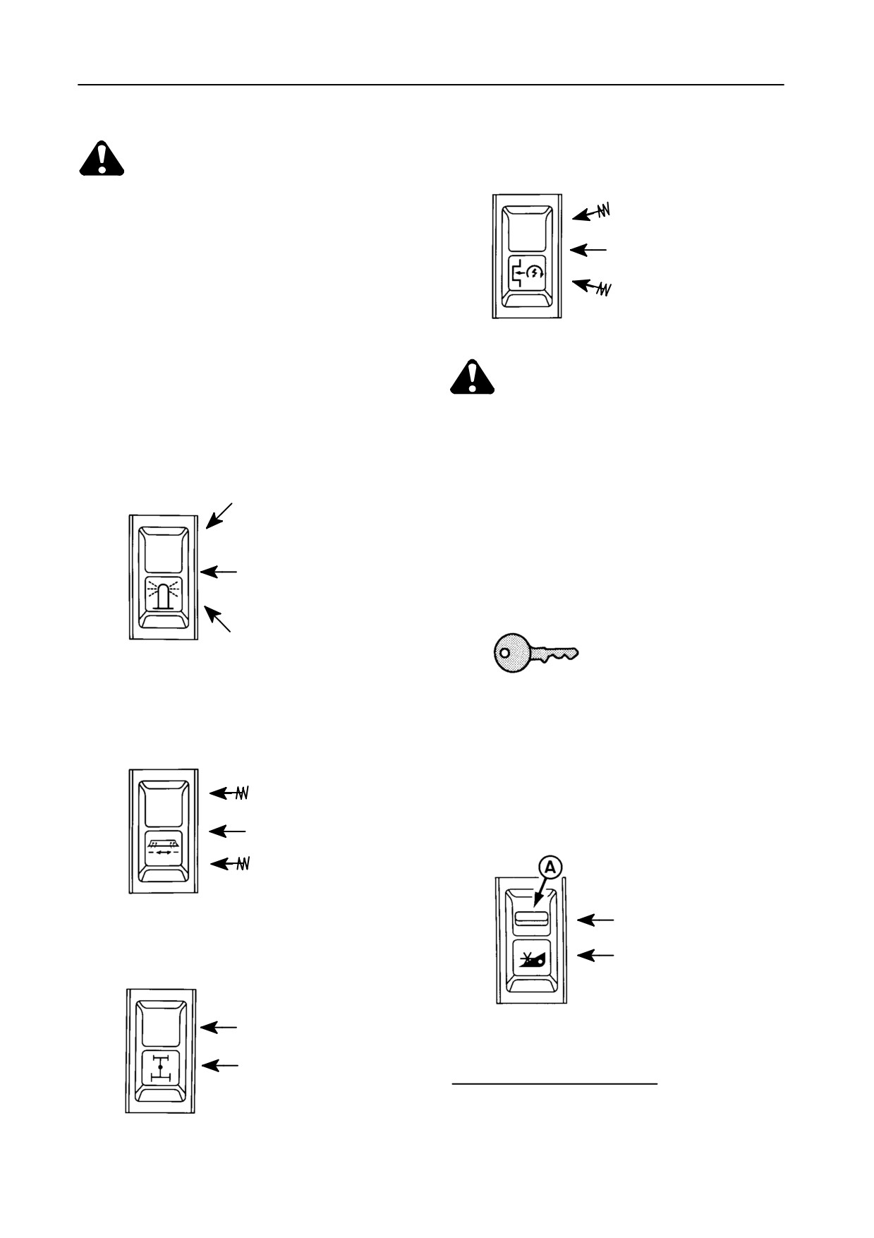
51
Engine reset rocker switch
WARNING:
Engine stop with header
S Do not drive on public roads with the
and threshing mechanism
operating lights switched on.
engaged (‘‘kill-stall’’)
S Avoid disturbing road users with
Neutral
long range operating lights (posi-
tion b of switch 47).
Reset function
48
Flashing light tumbler
switch
CAUTION:
S
Never press the upper part of the en-
gine reset rocker switch during road
transport !
OFF - Flashing lights ON for
5 seconds when grain tank
S
Press the reset rocker switch only af-
is
70% full (linked up with
ter turning the ignition key into the ig-
buzzer for 5 seconds)
nition position and before starting the
engine.
OFF - Flashing lights re-
main ON when grain tank is
70% full
(linked up with
buzzer for 5 seconds)
ON (road transport)
52
Ignition, engine start and
stop switch
Pos. 0 → Off
49
Straw chopper deflector
Pos. 1 → Contact
plates adjustment rocker
Pos. 2 → Contact
switch [if installed]
Pos. 3 → Starter motor
Towards left-hand side
Neutral
53
Header engagement tum-
bler switch
Towards right-hand side
OFF
50
Rear-wheel drive engage-
ment tumbler switch
[if
ON(1)
installed]
OFF
ON
(1) Not applicable to model TX62
2-13
OPERATION
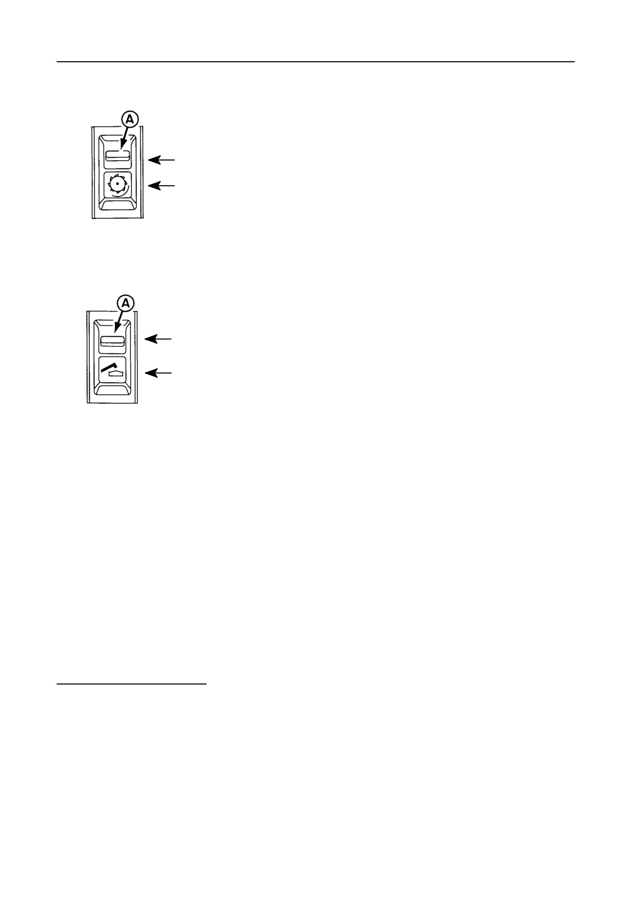
54
Threshing mechanism
engagement tumbler
switch(1)
OFF
ON(2)
55
Unloading system en-
gagement
tumbler
switch(1)
OFF
ON(2)
56
Model TX62
without automatic
header compensation
Instead of the switches 53 - 54 - 55, a
header compensation gauge 56 is in-
stalled (Fig. 10, insert).
(1) Not applicable for model TX62
(2) To engage, pull the spring-loaded lock A down and
press the lower part of the switch. To disengage,
press the upper part of the switch
2-14
SECTION
2
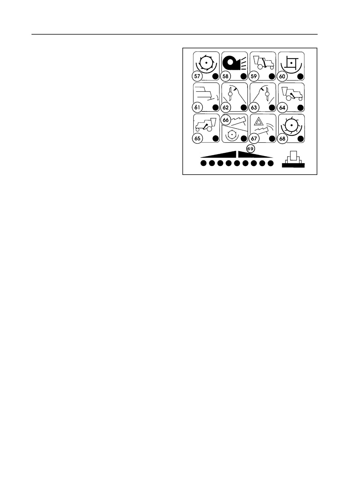
C Speed control module and header lateral
float indicator -- Figure 11
Low speed warning lights + audible signal (57-69)
57 Threshing drum
58 Cleaning fan
59 Clean grain cross auger and elevator
60 Beater
61 Not used
62 Straw chopper [if installed]
63 Not used
48252
64 Returns auger (left-hand side)
11
65 Returns auger (right-hand side)
66 Straw walkers
67 Straw walker blockage
68 Rotary separator
69 Header lateral float indicator [if applicable]
2-15
OPERATION
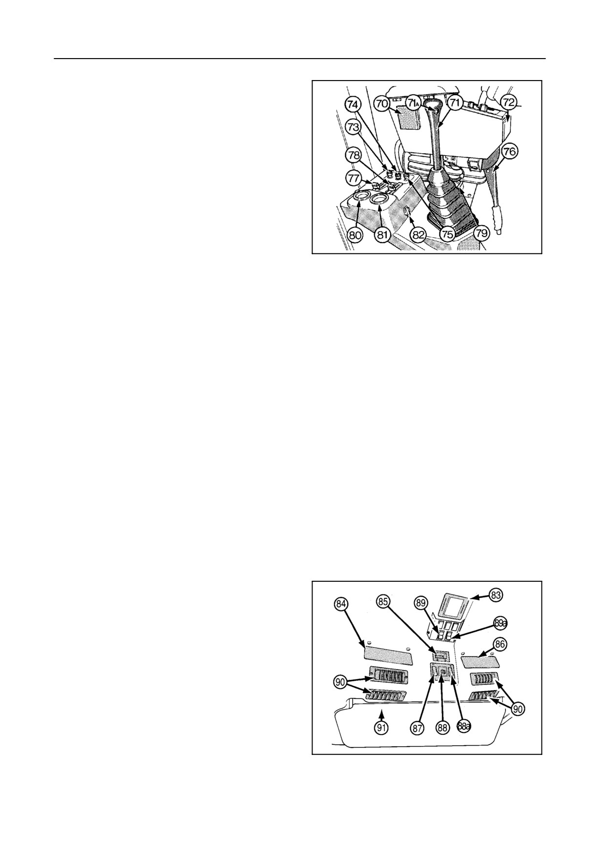
CONSOLE MODULE -- Figure 12
70
Drink storage space
71
Gearshift lever (All models, except TX67)
71A Hydrostatic oil pressure release button
(Push this button while shifting gears to take
away the hydrostatic oil pressure on the gear-
box)
(All models, except TX67)
72
Ashtray
42760
12
73
Heater control switch [if installed]
74
Fan speed control switch (3-speed)
75
Air conditioning control switch
76
Parking brake (All models, except TX67)
77
Air recycling control lever
78
Air vent control lever
79
Adjustable air vent
80
Fuel gauge
81
Engine coolant temperature gauge
82
12-Volt DC socket (live at all times)
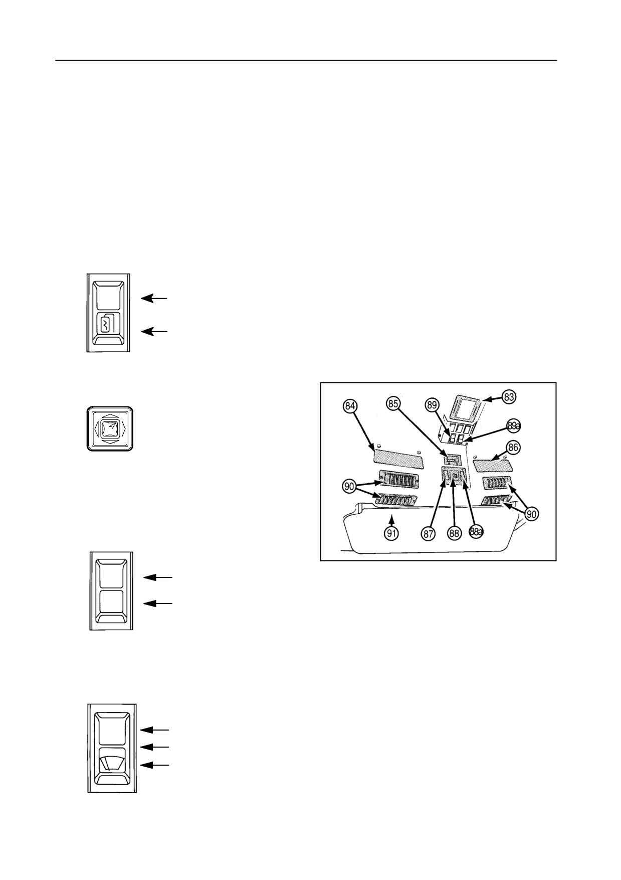
CAB ROOF INSTRUMENTS -- Figures 13 to 16
83 Cab interior light
- Left-hand side: ON/OFF switch
- Right-hand side: beam direction control
84 CB radio location with 12-volt DC connection and
CB antenna connection.
The CB antenna can be connected into the sock-
et located outside the cab above the cab door.
42757
85 Clock
13
Clock setting: H = hours, M = minutes
2-16
SECTION 2
86 Radio location with
-
12-Volt DC connection
- Loudspeaker connection
- Antenna connection
NOTE:
The antenna is located on the left-hand side in
the cab roof and is visible when removing the
roof.
87
Mirror heating tumbler
switch
Mirror heating OFF
Mirror heating ON
88
Mirror adjustment switch
Arrow to the left: left-hand
mirror
Arrow to the right: right-
hand mirror
88a
Tumbler selector switch
for mirror adjustment
(Germany only)
42757
14
Main mirror adjustment
Additional mirror adjustment
89
Windscreen wiper tum-
bler switch
Wiper OFF
Wiper ON (intermittent)
Wiper ON (continuous)
2-17
OPERATION
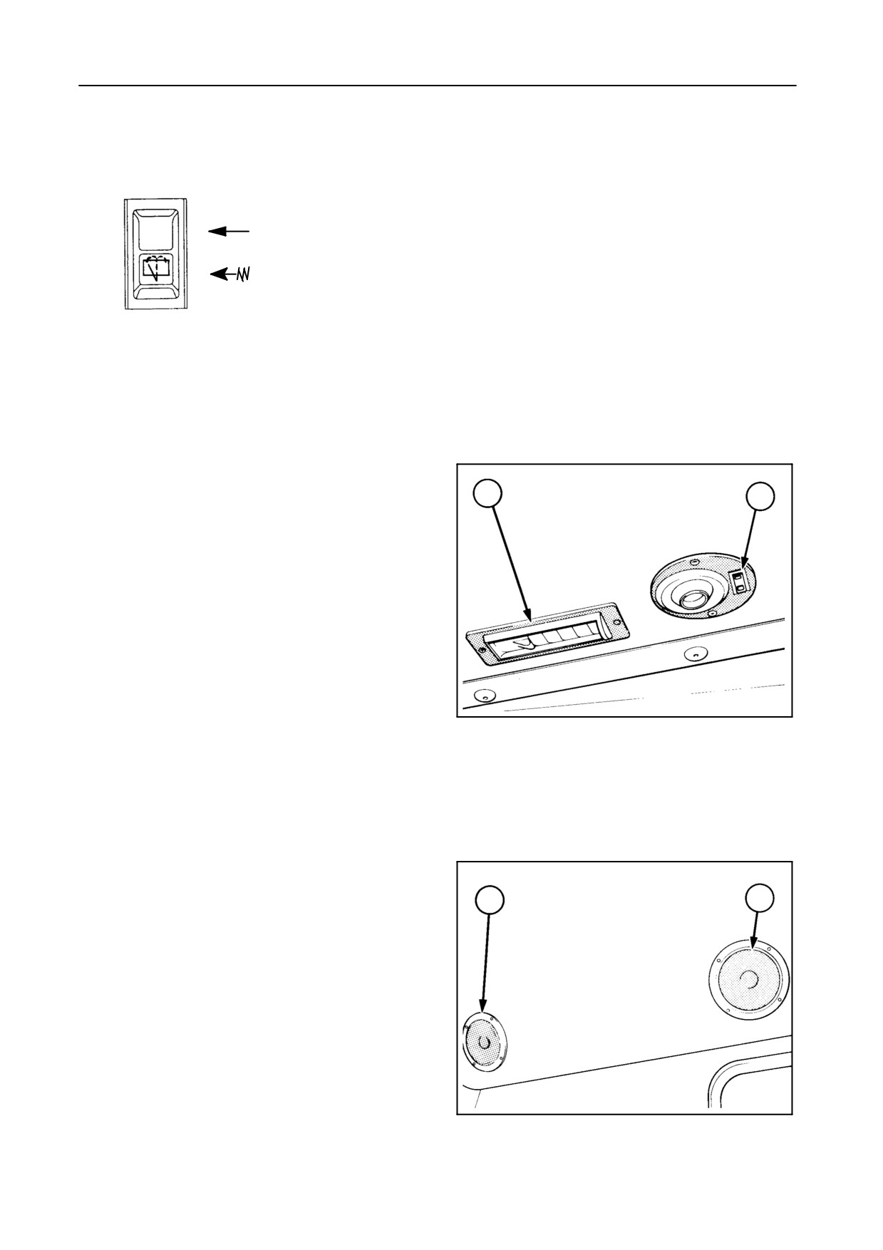
89a
Screen washer rocker switch
[if installed]
OFF
ON
90 Adjustable air vents
92
93
91 Sunshade
92 Adjustable air vent
93 Adjustable spotlight with ON/OFF switch
42752
15
94 Loudspeakers (standard)
94
94
42756
16
2-18
SECTION 2
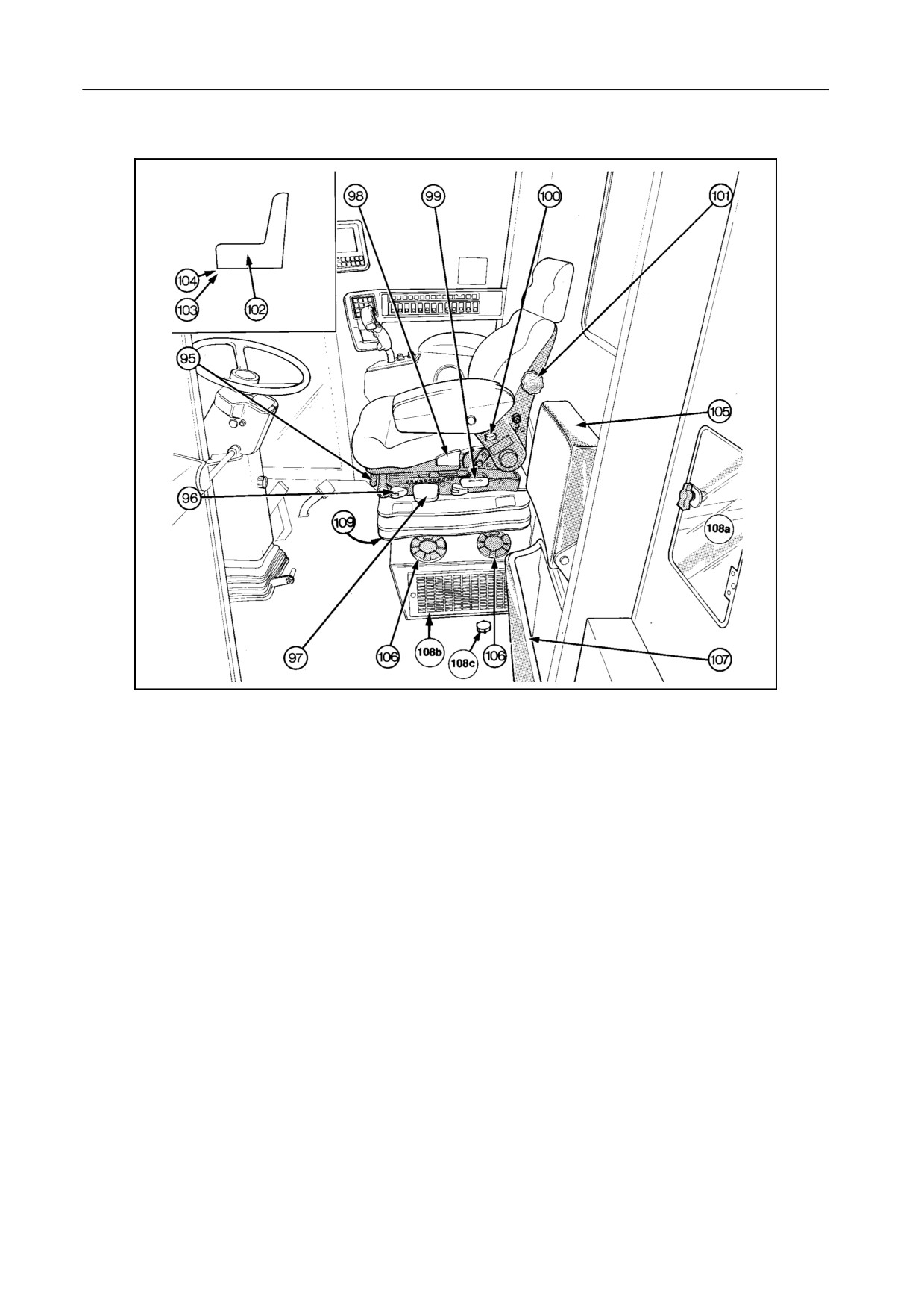
OPERATOR’S SEAT AND SURROUNDINGS -- Figure 17
43035
17
Air-suspended seat [if installed]
Standard seat [if installed]
102 Seat back rest inclination adjustment
95 Seat bottom adjustment
103 Weight adjustment
96 Horizontal seat suspension adjustment
104 Height adjustment
To lift: Lift seat to first or second audible stop.
97 Weight and seat height adjustment
To lower: First lift seat to the highest possible po-
Lifting the lever briefly will adjust the seat auto-
sition so the seat automatically returns to its low-
matically to the operator’s weight.
est position.
Hold the lever up or down to adjust the seat
height.
105 Buddy seat (not on models TX62-63)
106 Adjustable air vent
98 Seat back rest inclination adjustment
107 Storage space for operator’s manual
99 Fore and aft seat adjustment
108a Grain tank inspection door
100 Arm rest adjustment
This door allows to take a grain sample in a safe
way.
101 Lumbar adjustment
108b Recirculation filter (paper element)
Left-hand side: horizontal adjustment
Right-hand side: vertical adjustment
108c Reservoir for screen washer [if installed]
2-19
OPERATION
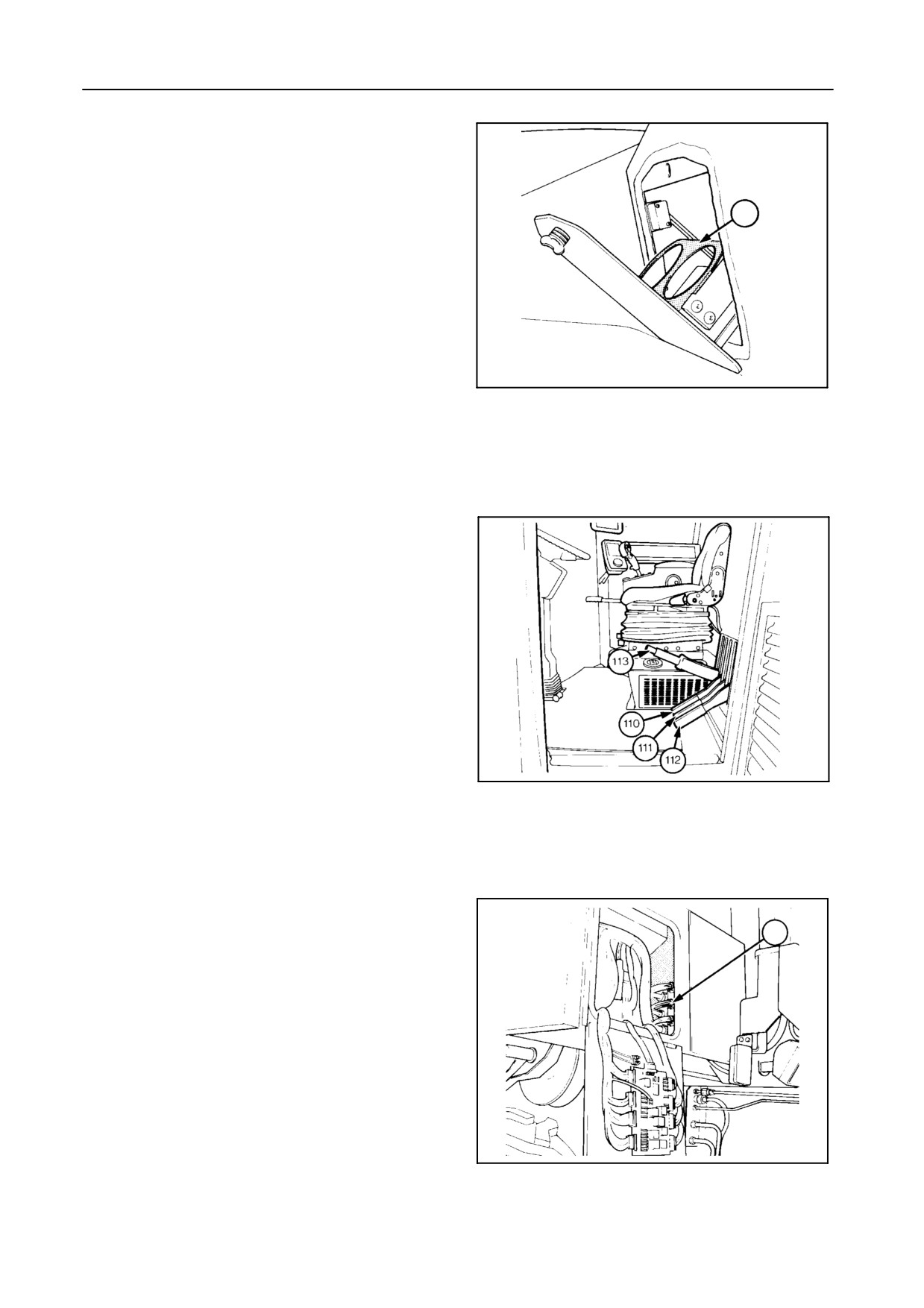
109 Drink storage space
NOTE:
If opened, the air conditioning and ventilation
system are switched off.
109
42753
18
Models TX62-63 only -- Figure 19
110 Header engaging lever
111 Threshing mechanism engaging lever
112 Unloading system engaging lever
113 Drum concave control lever
43036
19
FUSES AND RELAYS -- Figure 20
114
114 Access to fuses and relays
For more details, refer to Section 5 - ADJUSTMENTS
AND MAINTENANCE.
42750
20
2-20
SECTION 2
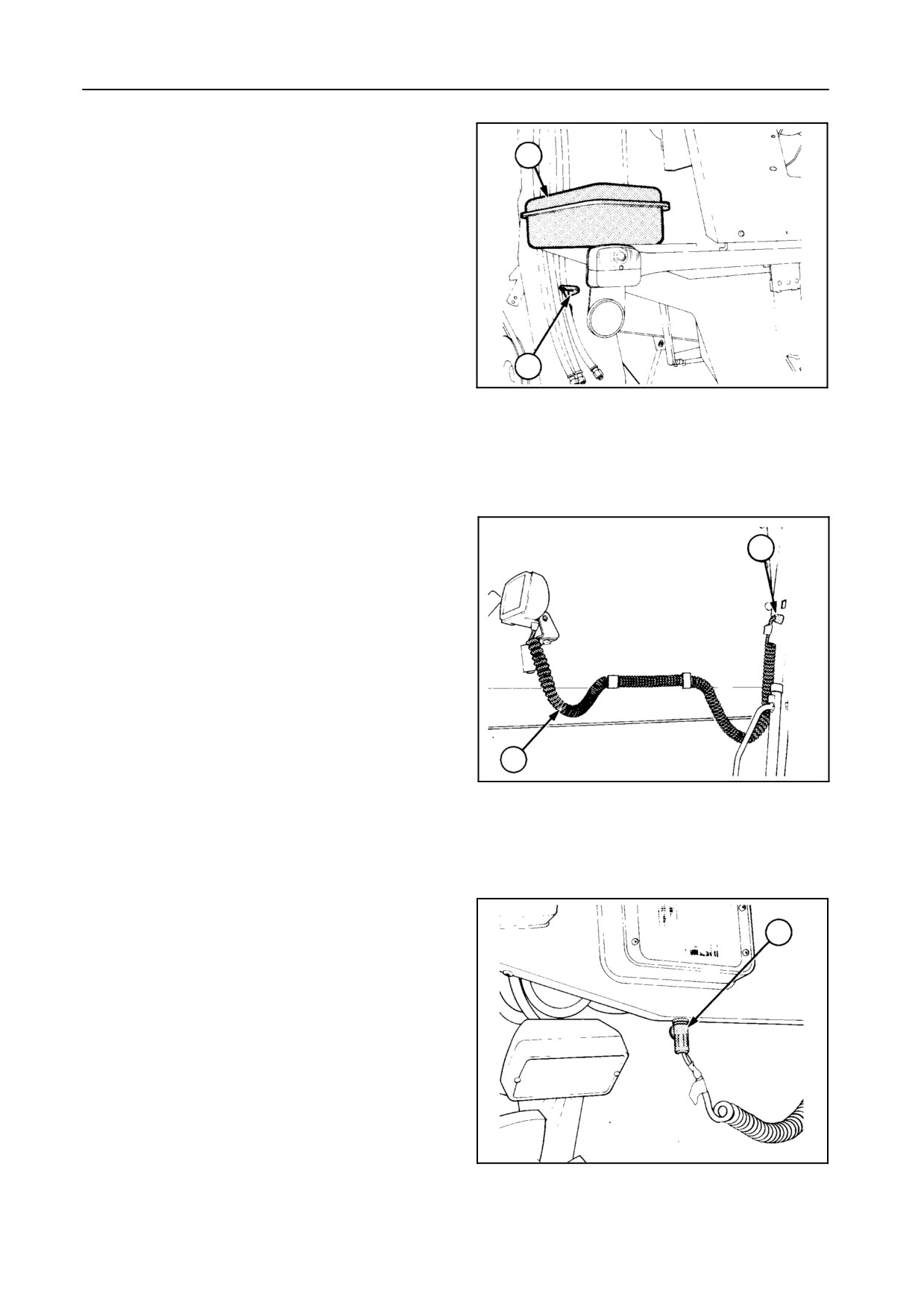
OTHER COMPONENTS [left-hand side] --
Figures 21 to 26
115
115 Toolbox
116 Battery key
Turn the key counterclockwise (1/4 turn) after
having switched off the ignition.
Turn the key clockwise (1/4 turn) before switch-
ing on the ignition key in the cab.
116
42761
21
117 Portable operating light [if installed]
A second support is available on the inside of the
118
straw hood.
117
42754
22
118 12-Volt DC socket (left and right)
118
Current is available when parking lights are
switched on.
42755
23
2-21
OPERATION
119
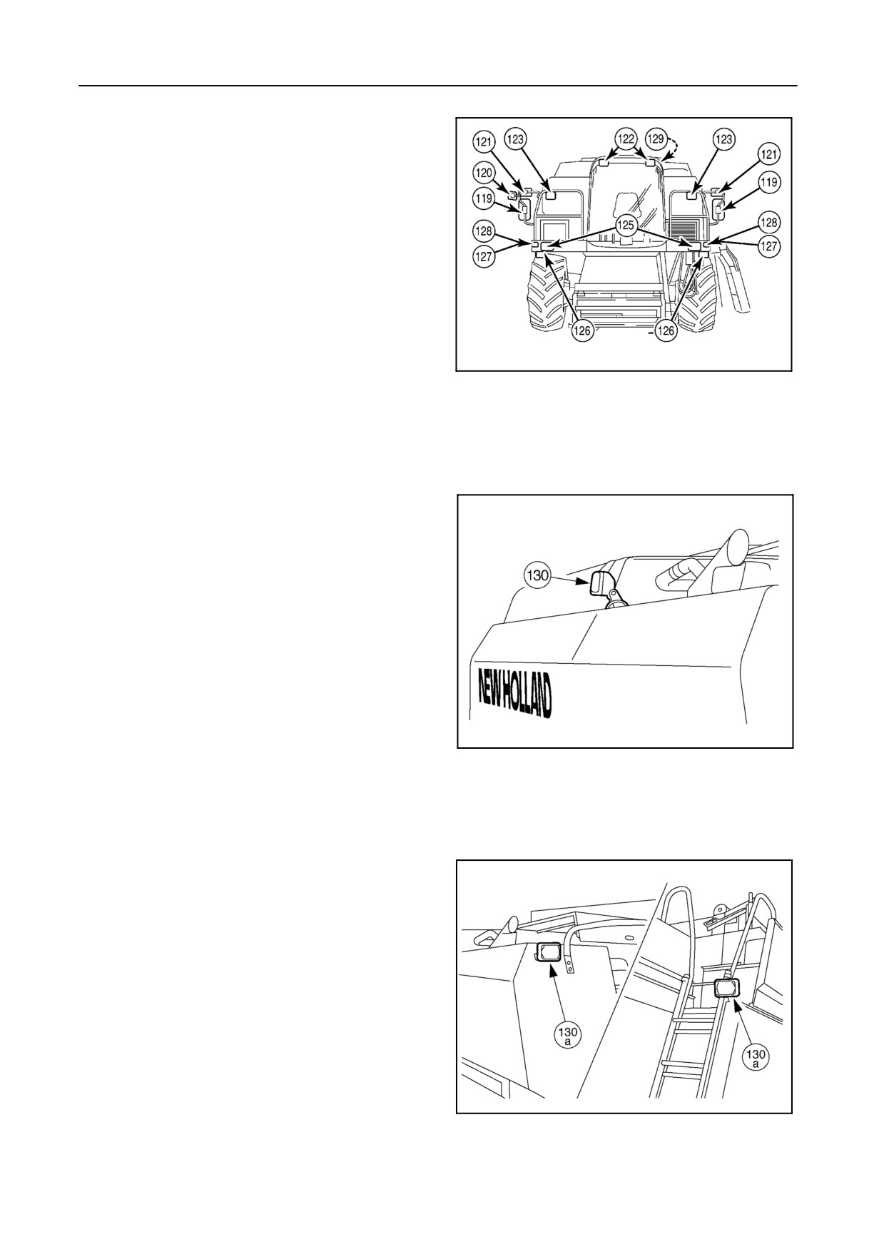
Main electrically adjustable mirrors
120 Additional electrically adjustable mirror
(Germany only)
121 Manually adjustable mirror
Mirrors 119, 120 and 121 are mounted on a hinged
support with fixed position.
122
Operating lights on cab
123
Twin operating lights on rails
30834
124
Right-hand operating light
24
125
Dimmed lights and headlights
126
Stubble lights [if installed]
127
Parking lights
128
Direction indicators
129
Antenna: Standard, built in between roof and
cab cover
130
Adjustable spotlight [if installed]
54733
25
130a Rear lights [if installed]
54734
26
2-22
SECTION 2
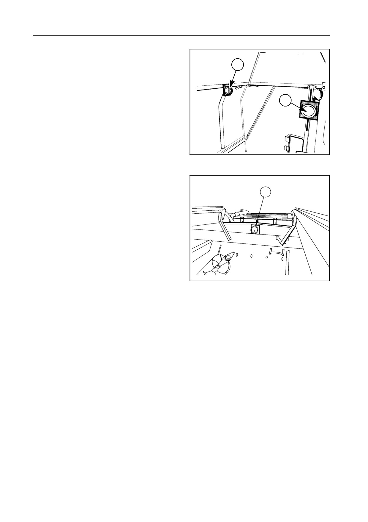
131 Grain tank light
132 Grain tank load sensor 70%
131
132
42956
27
133 Grain tank load sensor 100%
Message of full grain tank appears on the Info-
View monitor
133
52731
28
2-23
OPERATION
ACCESS TO MACHINE COMPONENTS -- Figures 29 to 35
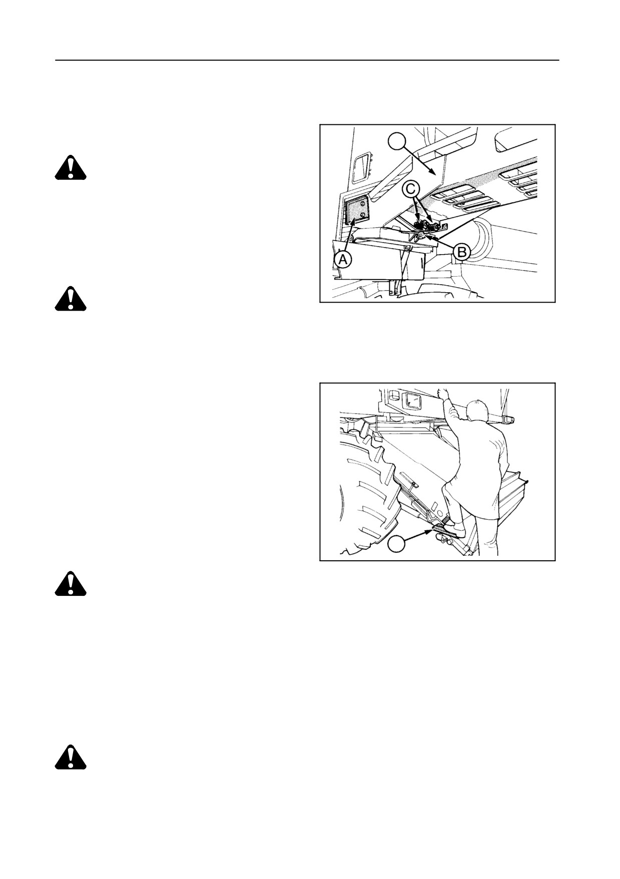
1
Access to operator’s platform
1
DANGER:
Never allow anyone to stand or hang on
the combine access ways while the com-
bine is in motion. These access ways are
only provided for entering and servicing
the (stopped) combine in a safe way.
42941
CAUTION:
29
S Always mount and leave the combine
in a safe way, i.e. use the steps and
guard rails provided and maintain a
3-point contact at all times.
S Pull up the ladder for road transport.
Brackets A (on both sides) are ad-
justed so that the ladder stands verti-
cal in the pulled-up position.
The ladder can pivot at B when the
combine is advancing or reversing
and the ladder contacts an obstacle.
The pivoting force is adjusted with
springs C. Spring length should be 63
mm.
2
42971
30
DANGER:
S Make sure bystanders cannot be hit
when lowering the ladder.
S Do not jump on the ladder when the
combine is advancing as the ladder
may pivot away.
2
Step fitted to the straw elevator to enable clean-
ing of the cab windscreen
CAUTION:
Keep hand on rail.
2-24
SECTION 2
3
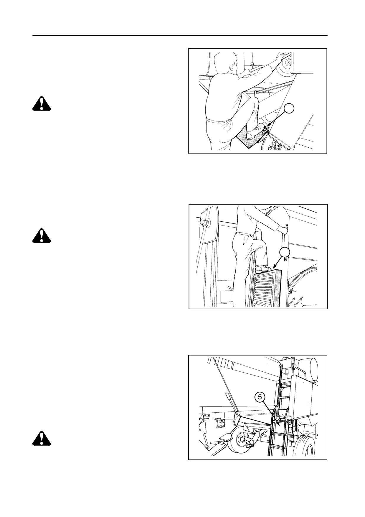
Step provided to gain access to the presieve
S to allow change of the rotary separator rpm
S to allow adjustment of the straw walker belt
tension
CAUTION:
3
Keep hand on rail.
42944
31
4
Step provided to allow opening of the grain tank
covers at the front side
CAUTION:
Keep hand on rail.
4
42943
32
5
Access to engine compartment and fuel tank filler
cap
Lowering the ladder to the engine platform with
the engine running will cause the engine to stop. It
is, however, possible to start the engine while the
ladder is in the lowered position.
IMPORTANT:
Be aware that, if the engine is running with the
ladder in the lowered position, the engine
protection is not working.
CAUTION:
Raise the ladder when travelling on pub-
43039
lic roads.
33
2-25
OPERATION
6
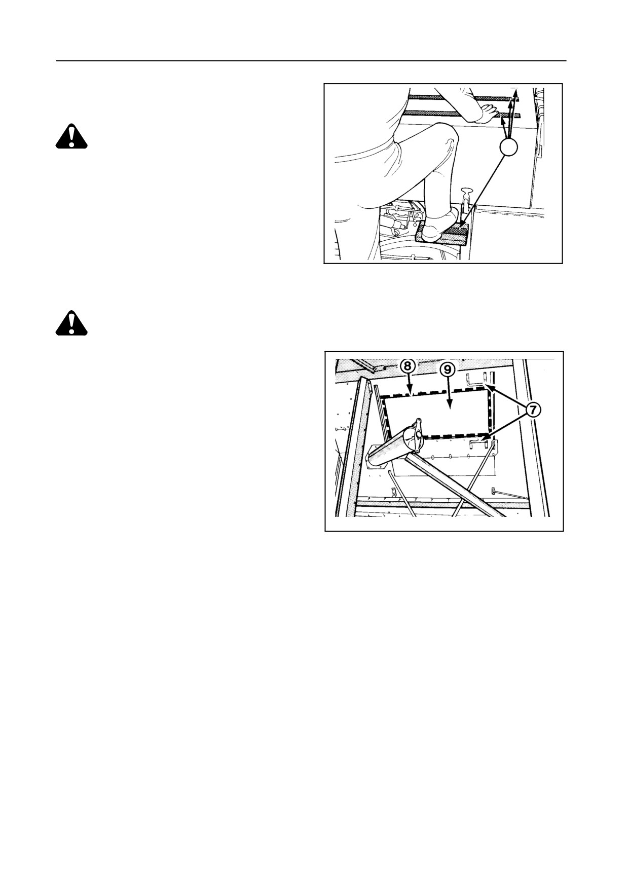
Step and antislip strips provided to allow opening
of the grain tank covers at the rear side
CAUTION:
6
Do not stand up on the engine cover.
7
The grain tank is accessible through the open
grain tank covers, described above, using steps 7
42942
to climb inside.
34
Remove cover 8 to gain access to the rotary sep-
arator cover 9.
CAUTION:
S Shut off the engine and remove the
ignition key before entering the grain
tank.
S Do not climb in the grain tank from the
front side.
30366
35
2-26
SECTION 2
BEFORE DRIVING THE COMBINE
1.
Read this Operator’s Manual carefully, especially
8. Sit down on the operator’s seat and adjust it ac-
the paragraphs headed ‘‘Safety Precautions’’ and
cording to your weight and size.
‘‘Starting the Engine’’.
9. Adjust the steering wheel to the desired position.
2.
Check all chain and belt tensions (refer to Section
10. Adjust the rear-view mirrors, if necessary. See
5 -- ADJUSTMENTS AND MAINTENANCE).
page 2-16.
3.
Check all pressures daily. Keep the tyres inflated
11.
Start the engine. Refer to the next paragraph
to the pressures given in Section 9 -- SPECIFI-
headed ‘‘Starting the Engine’’.
CATION.
12. Raise the ladders when driving on public roads.
4.
Check the wheel nuts torque daily during the
first week of operation and thereafter on a weekly
13. Ensure the unloading tube is in the closed posi-
basis.
tion.
Refer to Section 9 -- SPECIFICATION.
14. Disengage the parking brake.
5.
Check the engine oil and coolant level (ensure the
15. Move the throttle switch into the upper position
machine is standing on level ground). Refer to
(i.e. maximum speed).
Section 3 -- LUBRICATION.
16. Raise the header to its highest position.
6. Check the hydraulic and hydrostatic oil reservoir
level with all hydraulic cylinders retracted and the
IMPORTANT:
header lowered to the ground (machine standing
To prevent the hydraulic oil from overheating,
on level ground). Add oil if necessary. Refer to
do not hold the header height control switch in
Section 3 -- LUBRICATION.
the operating position longer than is neces-
sary. The same applies to the hydraulic con-
7. Lubricate the combine completely as described in
trols for the reel height and the reel fore and aft
Section 3 -- LUBRICATION.
adjustment.
STARTING THE ENGINE
Ensure you are thoroughly familiar with the instru-
DAILY START-UP PROCEDURE
ments and controls before starting the engine for the
first time.
Proceed as follows :
To start the engine safely, follow the points as outlined
1. Carry out the routine engine service, i.e. check
below.
coolant, oil and fuel tank levels (refer to Section 5
-- ADJUSTMENTS AND MAINTENANCE). En-
sure the battery key is in the ‘‘ON’’ position.
CAUTION:
Before starting the engine, ensure there
2. Ensure the engaging tumbler switches for the
is enough ventilation and everyone is
header, threshing mechanism and unloading
standing clear of the combine.
mechanism are in OFF position.
2-27
OPERATION
3.
Check that both brake pedals are coupled to-
gether and that the parking brake is engaged.
4.
Ensure the gearshift lever and the ground speed
control lever are in the neutral position.
5.
Press the throttle switch into the bottom position
(i.e. minimum speed).
6.
Insert the key into the ignition-and-stop switch
and turn the key clockwise to the ignition position.
Inspect engine oil pressure, hydrostatic oil pres-
sure and battery charge warning lights for proper
functioning.
NOTE:
The audible signal will sound (indicating park-
ing brake engaged).
7.
Before starting the engine, warn bystanders by
sounding the horn several times.
8.
Press the engine reset rocker switch 51 (bottom
position).
9.
Turn the ignition key clockwise to engage the
starter motor.
42753
If the engine fails to start after 30 seconds, re-
36
lease the starter button for about 1 minute before
re-engaging the starter motor.
10. As soon as the engine starts, release the starter
switch.
ATTENTION :
S Allow the engine to run for one minute at low
idle before moving off, to ensure adequate
lubrication of the turbocharger bearings.
S If the audible alarm does not cease func-
tioning when the parking brake is disen-
gaged, or if the warning lights for the engine
oil pressure or hydrostatic charge pressure
do not extinguish after the first few seconds
of idling, stop the engine immediately and
contact your dealer for assistance.
2-28
SECTION 2
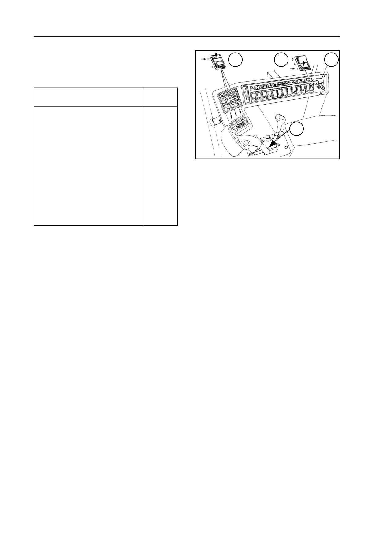
The table below shows a summary of the starting con-
1
4
5
ditions (refer to Figure 37).
Sequence
Position
Battery key
ON
Header engagement tumbler switch 1
OFF
2
Threshing mechanism engagement
OFF
tumbler switch 1
51381
Unloading system engagement tum-
OFF
37
bler switch 1
Ground speed control lever 2
Neutral
Turn the ignition key to the contact
Ignition
position 5
ON
Reset the engine with the engine
--
reset rocker switch 4
The engine can now be started by turning the igni-
tion key clockwise to engage the starter motor.
STOPPING THE ENGINE
Proceed as follows :
3. Remove the key from the ignition-and-stop
switch.
1. Move the throttle switch to its bottom position and
let the engine run at idling speed for one minute.
2. Turn the key counterclockwise to stop the engine.
4. Apply the parking brake.
2-29
OPERATION
DRIVING THE COMBINE
CAUTION:
The combine rear end swings out when
changing direction. Take care when tak-
ing turns.
1. Ensure that the ground speed control lever is in
the neutral position.
2. Move the gearshift lever into the desired gear.
S For field operation, use first, second or third
gear, depending upon the circumstances.
S For manoeuvring in confined spaces, use first
gear.
S For road transport, use third or fourth gear.
3. Release the handbrake.
CAUTION:
Keep brake pedals depressed while re-
leasing the handbrake.
Ensure not to touch the hydrostatic lever
when releasing the handbrake.
4.
Move the ground speed control lever slightly for-
ward from the neutral position to advance, or from
the neutral position rearwards to reverse.
NOTE:
When reversing the combine, an audible alarm
will automatically warn bystanders.
5.
Familiarize yourself with the different steering
and driving characteristics.
IMPORTANT:
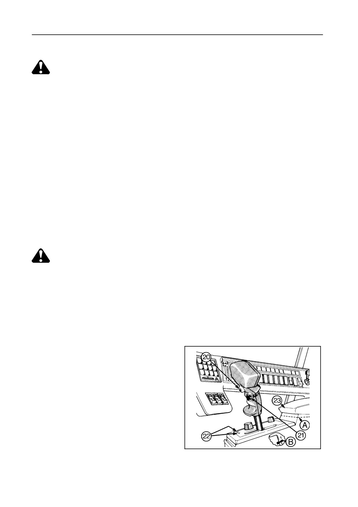
In case of hydrostatic control failure, the emer-
gency rocker switch B can be used. To move
forward pull the switch up. To reverse push the
switch down. Refer to item 23. However, use
this switch only if really necessary to drive the
42759
machine off the road.
38
2-
30
SECTION 2
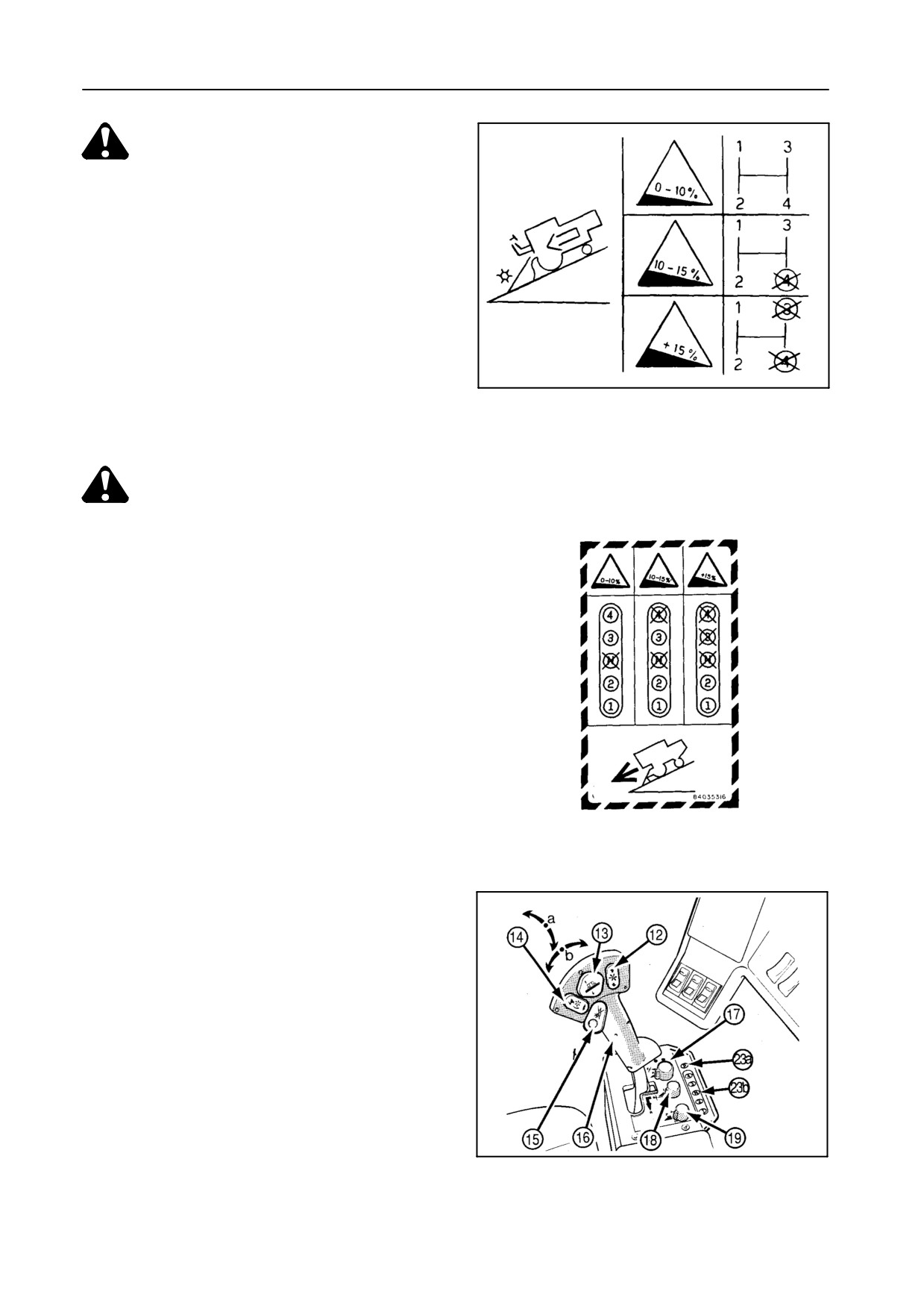
WARNING:
To prevent runaway of the combine (i.e.
when the ground speed increases during
downhill driving and it is impossible to
reduce speed with the ground speed con-
trol lever), it is necessary to shift into a
lower gear appropriate to the steepness
of the hill.
This information is also given on a decal
situated on plate A under the arm rest
50672
cover. See Figure 38.
39
All models, except TX67
CAUTION:
Never drive on public roads with any of
the mechanisms engaged.
The combine model TX67 is equipped with a remote
emergency and parking brake, and with a remote
gearshift system.
1
TX67
40
EMERGENCY AND PARKING BRAKE
The parking brake is operated by pressing button 23a
[symbol P] (Fig. 41). A control light and an audible
signal indicate the parking brake activation. The hy-
drostatic system will be disabled.
The emergency brake button has two positions:
S The first position brings the hydrostatic system
into neutral.
42765
S The second position (i.e. button fully pressed) op-
erates the friction brake.
41
2-31
OPERATION
WARNING:
Pressing the ‘‘P’’ button while driving the
combine will cause the combine to stop
abruptly (emergency stop).
CAUTION:
Do not press button P to actuate the
handbrake during road transport unless
it is required as an emergency stop!
After an emergency stop, bring the ground speed
control lever to neutral and release the brake by push-
ing button P to reset the system.
GEARSHIFTING SYSTEM
A five-button console (1--2--N--3--4) with indicator
lights indicates the selected gear.
Selecting a gear is only possible with the ground
speed control lever in neutral position. Press a button
to select a gear. The parking brake is automatically
engaged and the hydrostatic system will be disabled.
An indicator light will start to flash and comes on
steadily when the gearshifting is completed. The
parking brake will reset to its previous state and the
operator can take over hydrostatic control.
2-32
SECTION 2
SELF-DIAGNOSTICS -- Figures 42 and 43
4 Hz
4 Hz
P
P
P
P
P
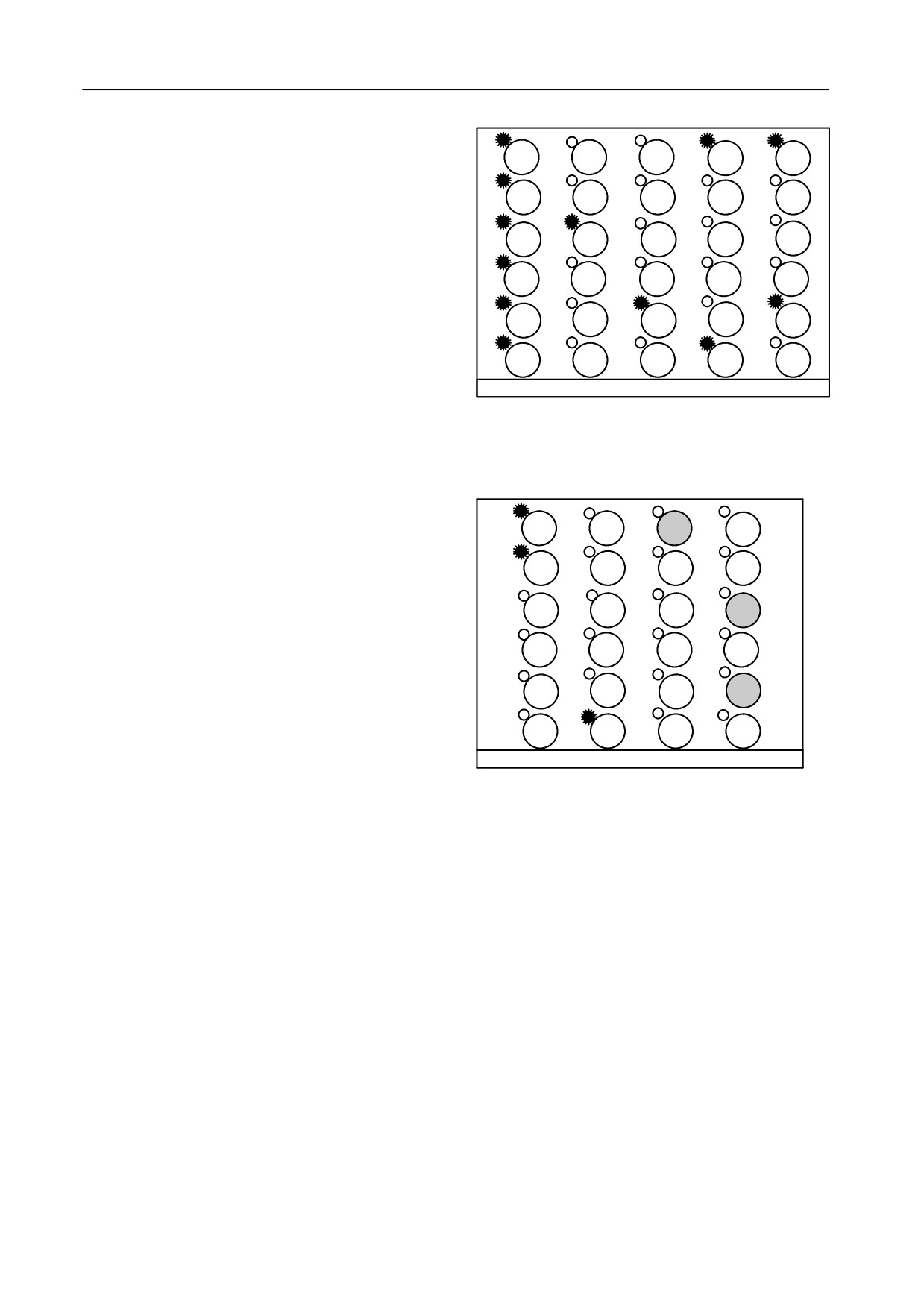
The blinking sequence of the LED’s on the remote
control console identifies a message/error report. Er-
4
4
4
4
4
ror reports can show up after switching on contact or
2 Hz
after a gearshift. It is possible to clear the errors by
3
3
3
3
3
pressing button P. If not, contact your local dealer. To
reset the system, press the buttons of 2nd and 3rd
N
N
N
N
N
gear simultaneously.
4 Hz
4 Hz
2
2
2
2
2
4 Hz
1
1
1
1
1
1
2
3
4
5
52447
Message/Error report
42
1. Check all keyboard LED’s after contact or reset
(control lights will show up for 1 second).
4 Hz
2. Message: Searching for 3rd gear.
P
P
P
P
4 Hz
3. Error: Gear motor did not reach the selected gear.
4
4
4
4
4. Error: Pressure release valve problem.
3
3
3
3
5. Error: Parking brake valve problem.
N
N
N
N
6. Error: Gear motor problem.
2
2
2
2
4 Hz
7. Error: More than 1 microswitch activated.
1
1
1
1
6
7
8
9
52448
8. Press “P” to clear all errors.
43
9. Press “2” and “3” to reset the system.
2-33
OPERATION
HEADER
ATTACHING THE HEADER TO THE COMBINE --
Figures 44 to 48
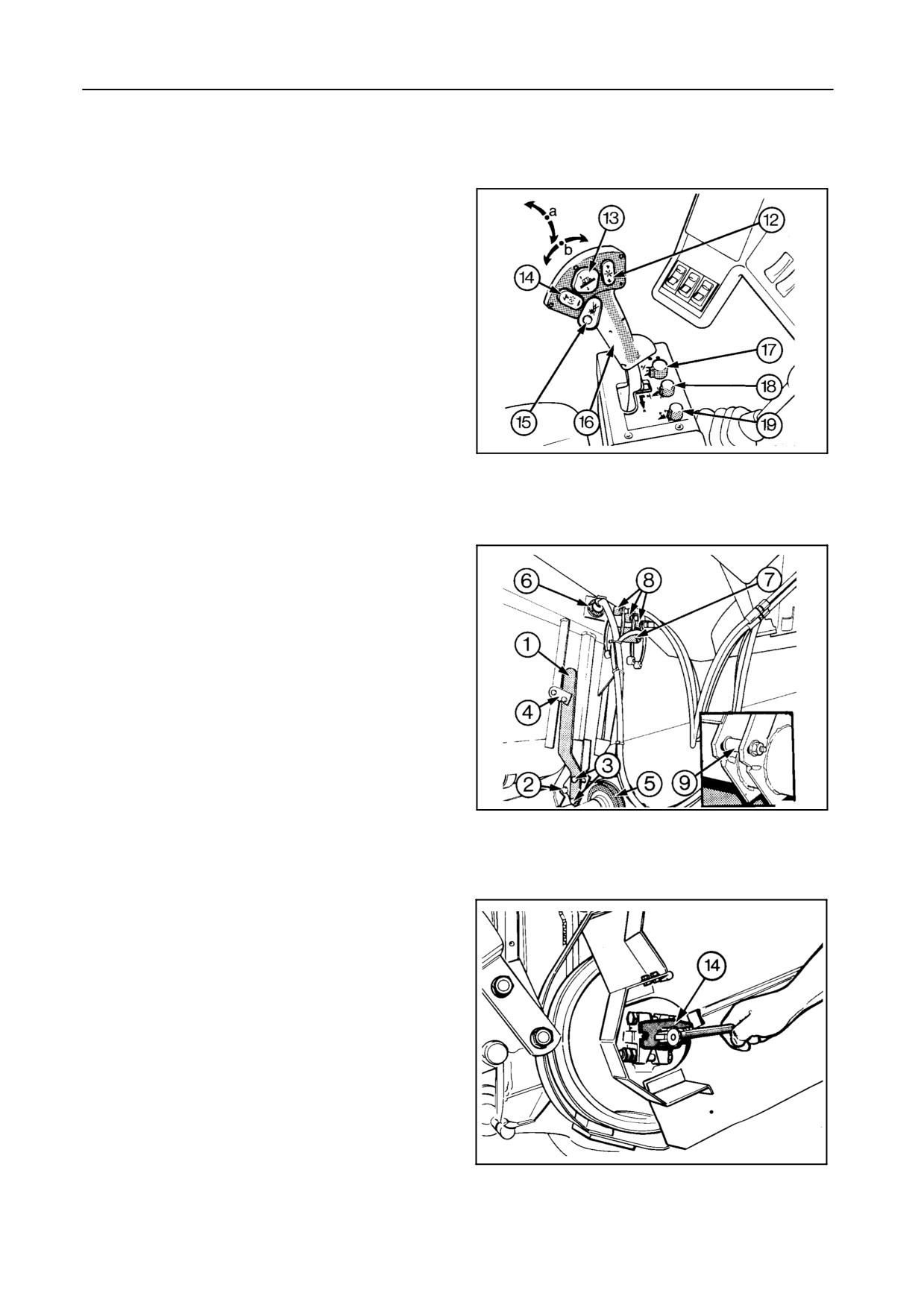
First, position selector switch 17 in the arm rest into
the ‘‘manual control’’ (i.e. rear) position (not applica-
ble for model TX62).
To attach the header to the combine, proceed as fol-
lows:
1. Position the combine to align the straw elevator
with the header aperture.
42765
44
2. Move the combine to position the straw elevator
against the header. Hook on the header, and
raise the straw elevator and header.
3. Attach the quick-attach lever 1 so that the hooks 2
are in full contact with pins 9. If not, adjust lever 1
with bolts 3 so that some resistance is felt when
engaging latch 4 over lever 1.
4. Connect header drive coupling 5. Use the special
tool 14 fitted to the right-hand side of the straw
elevator to bring the splines of the straw elevator
bottom shaft in line with the splines of the header
42751
p.t.o. shaft.
45
5. Connect electrical plug 6 and plug 7 [accessory].
55032
46
2-34
SECTION 2
6. S Combine equipped with grain header only :
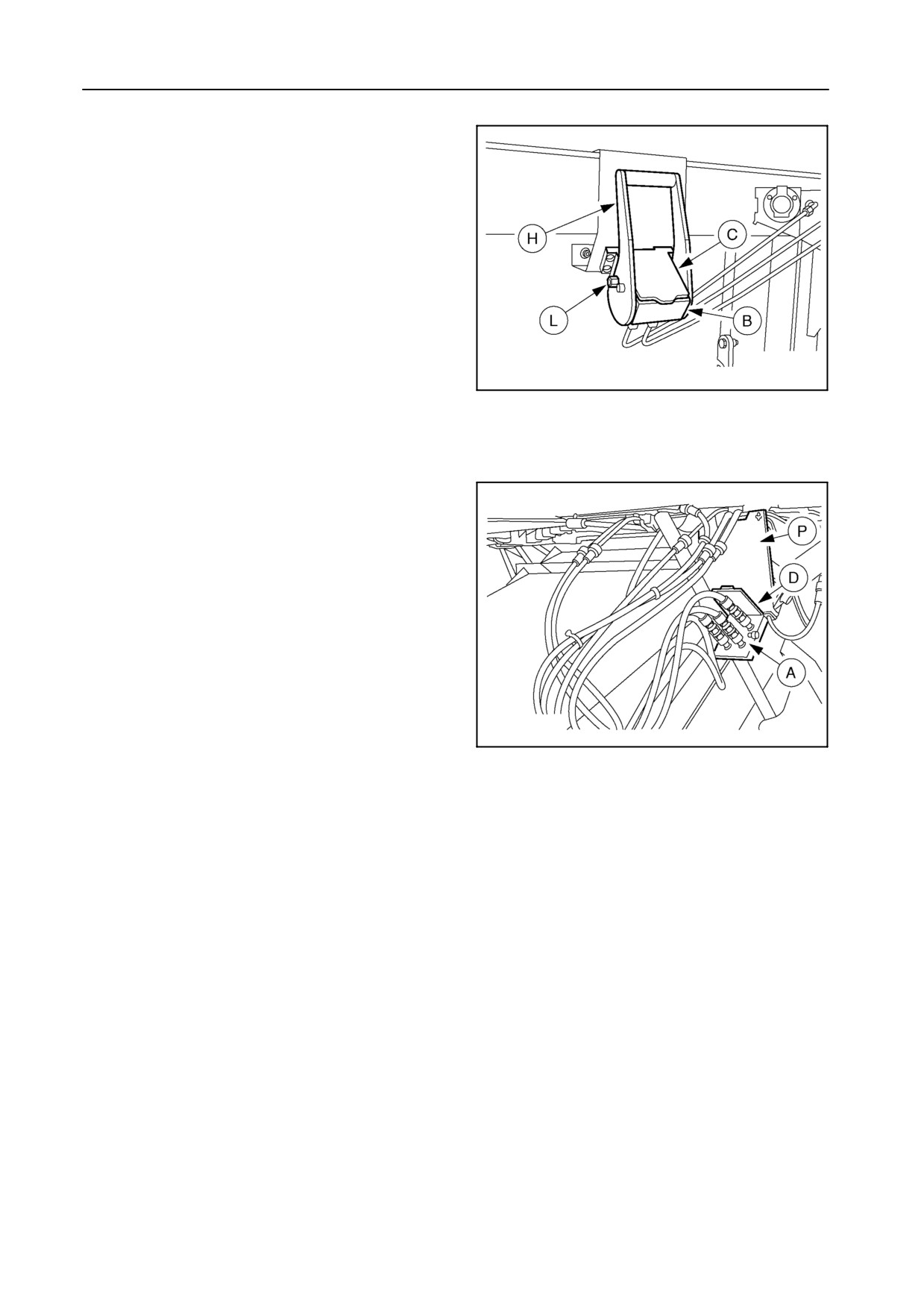
Connect the hydraulic hoses to the corre-
sponding hydraulic couplings
8
on the
header.
-- Reel height adjustment : central coupling
-- Reel fore and aft adjustment : coupling
marked with white and black rings (as on
the header)
Fit the blanking plugs into each other.
S Combine equipped with grain header only
54735
and quick-release coupler:
47
Open cover C, bring hydraulic block A onto B
and turn down handle H until lock L jumps into
its security groove. Close cover D.
54736
48
2-35
OPERATION
DETACHING THE HEADER FROM THE COMBINE
-- Figure 49
Proceed as follows :
1.
Combine equipped with grain header only :
Set the reel in its lowest and rearmost position.
2.
Disconnect the following parts :
S Header drive coupling
S Electrical connection(s)
S Hydraulic hoses or quick-release coupler [if
installed]
3.
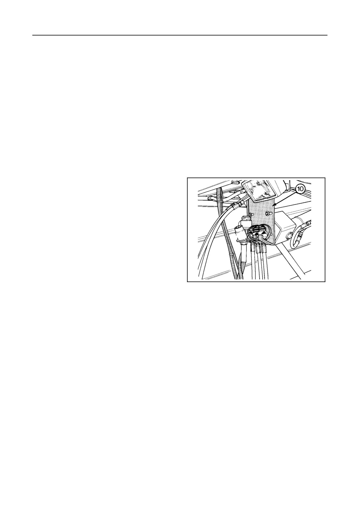
S Fit the blanking plugs into the hydraulic cou-
plings on the header and into the hydraulic
hoses. Hook the hydraulic hoses onto the
support plate 10.
S If a quick-release coupler is installed (refer to
Figures 47 and 48):
Release the hydraulic quick coupler by pres-
sing lock L and turning over handle H. Close
42758
cover C, open cover D and hook hydraulic
block A onto plate P.
49
4.
Position selector switch 17 (Fig. 44) in the arm
rest into the ‘‘manual control’’ (i.e. rear) position
(not applicable on model TX62).
5.
Release quick-attach lever 1 (Fig. 45).
6.
Position the header on level ground.
7.
With the engine running at idle speed, lower the
straw elevator to release it from the header, then
move the combine rearwards.
IMPORTANT:
Avoid possible oil contamination by properly fit-
ting the blanking plugs into the hydraulic quick-
couplers or into each other during operation.
2-36
SECTION 2
TOWING THE COMBINE
Towing the combine is not recommended, but if it
ATTENTION:
must be towed, the following steps must be taken:
Towing the combine with selected gear will im-
mediately lead to irreparable hydrostatic dam-
1. Move the hydrostatic lever into neutral and switch
age.
off the rear-wheel drive.
2. Select neutral gear.
IMPORTANT:
Should the combine become stuck in the mud,
Model TX67: If not possible with the remote gear-
always tow the combine with a cable or chain
shifting, refer to Section 6 -- TROUBLESHOOT-
attached to the traction axle.
ING.
Do not tow the combine with a cable attached
3. Release the handbrake.
to the steering axle or to the frame.
Model TX67: If not possible with the remote park-
ing brake button, refer to Section 6 -- TROUBLE-
SHOOTING.
CAUTION:
4. Tow at a maximum speed of 16 km/h.
Do not use a rope. Should the rope break,
5. Provide adequate warning signals to make other
energy stored in it could cause bodily in-
road users aware that the combine is being towed.
jury.
WHEELS AND TYRES
TYRE PRESSURE
Check the wheel nuts torque daily during the first
week of operation and thereafter on a weekly basis.
The life and performance of the tyres depends largely
upon maintaining the correct pressure. Keep the
tyres inflated to the pressures given in Section 9 -
The wheel nuts torques are given in Section 9 -
SPECIFICATION.
SPECIFICATION.
2-37

SECTION 3
LUBRICATION
GENERAL INFORMATION
The service intervals are displayed on the InfoView
monitor as described in Section 4 - FIELD OPERA-
TION.
The hours shown are counted engine hours. The dis-
Your model TX combine is designed to require mini-
play starts to blink when the interval is exceeded. Af-
mum lubrication. However, regular lubrication is the
ter having carried out the necessary service works as
best insurance against delays and repairs and greatly
described, the hours can be cleared as explained in
increases the life of the machine.
Section 4 - FIELD OPERATION.
Use only top grade lubricants stored in clean vessels.
GREASE FITTINGS AND LUBRICATION INTER-
VALS
Recommended lubricants and amounts are summa-
Before greasing the machine always wipe any dirt
rized at the end of this section.
from the grease fittings and then apply a good grade
of grease. Use Multipurpose grease AMBRA GR9
(ref. NH710A) or AMBRA GR75MD (ref. NH720A), or
grease classified under NLGI 2.
CAUTION:
Always stop the machine before lubricat-
All points, except those with special notations, should
ing and observe the following precau-
be lubricated until the grease is forced out around the
tions:
bearings and then the excess grease should be wiped
off.
S Disengage all drives.
All grease fittings on the machine are indicated with a
S Lower the header to the ground, or
grease decal on which the time interval is mentioned.
raise the header and engage the cylin-
See the Figure below.
der safety latch.
S Switch off the combine engine, en-
gage the parking brake and remove
the ignition key before leaving the op-
erator’s platform.
3-1
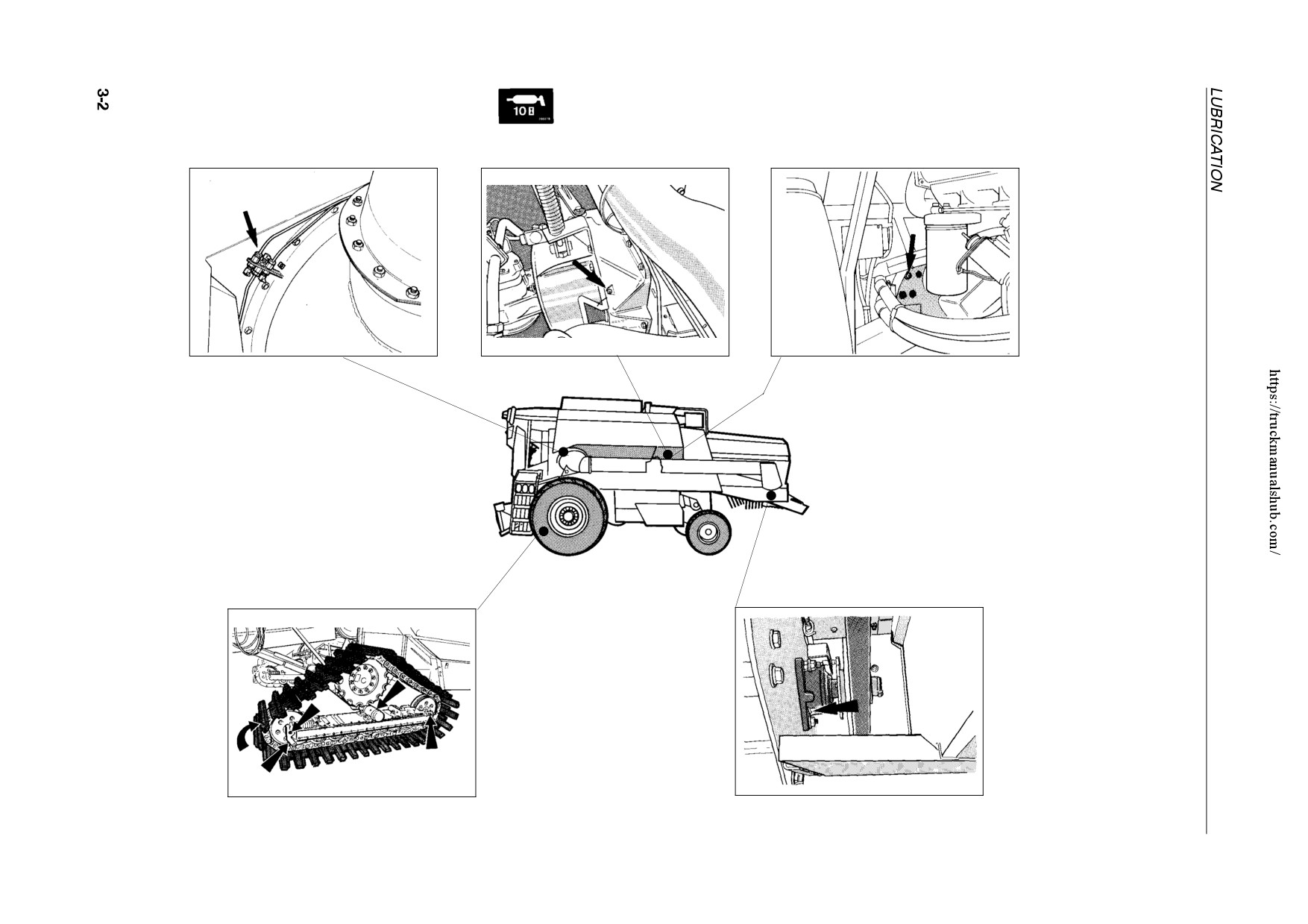
10 hour intervals (daily) -- Left-hand side
Engine tail shaft bearings
Unloading tube swivel ring (4)
(TX62-63-64PLUS-65PLUS-66PLUS-67) (*)
Engine tail shaft bearings (TX68-68PLUS) (*)
42769
30235
42770
1
2
3
Straw chopper rotor bearing
Tracks (5) [if installed]
[if installed]
55005
30352
(*): max. 2 gun strokes/time!
5
4
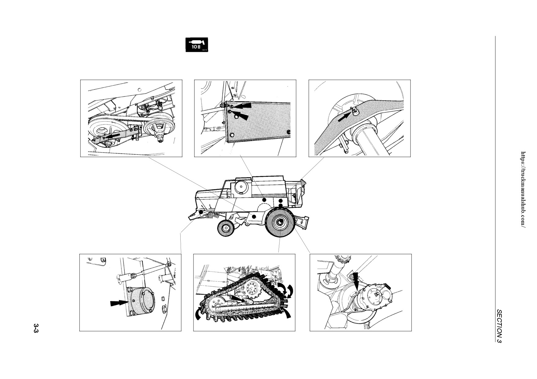
10 hour intervals (daily) -- Right-hand side
Drum variator:
Thrust bearing on intermediate shaft
Drum variator:
Cleaning fan variator thrust bearing
Intermediate shaft bearing
Thrust bearing on drum shaft
42772
42773
42790
6
7
8
Drum variator with speed reducer
Straw chopper [if installed]:
[if installed]
Rotor bearing
Tracks (5) [if installed]
- Thrust bearing on drum shaft
42811
55004
42969
11
10
9
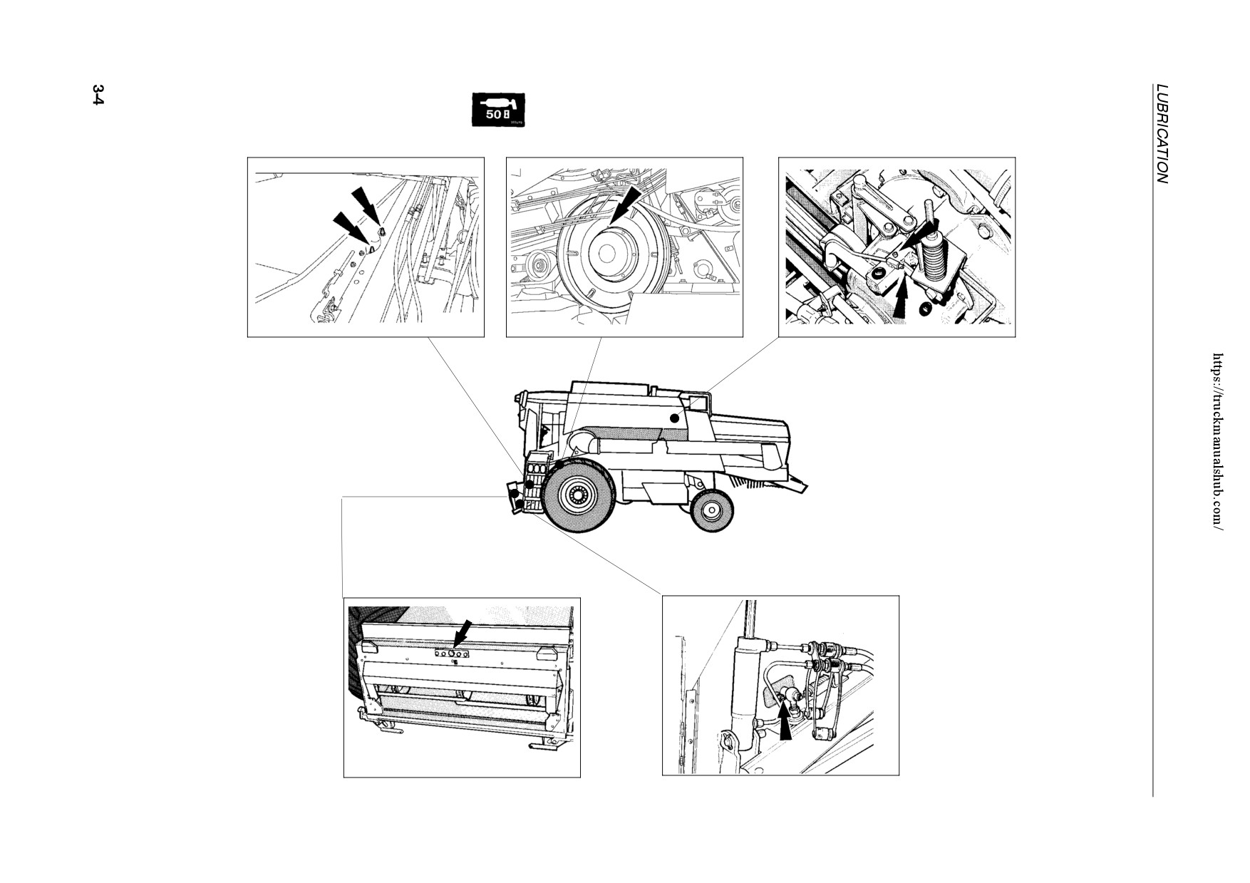
50 hour intervals -- Left-hand side
Straw elevator middle shaft bearing
Straw elevator upper shaft bearing
Straw elevator slip clutch
Main idler and pivot shaft
54721
55751
20860
12
13
14
Straw elevator head pivot point
[if fitted with lateral flotation]
Straw elevator front shaft bearing
42879
30512
15
16
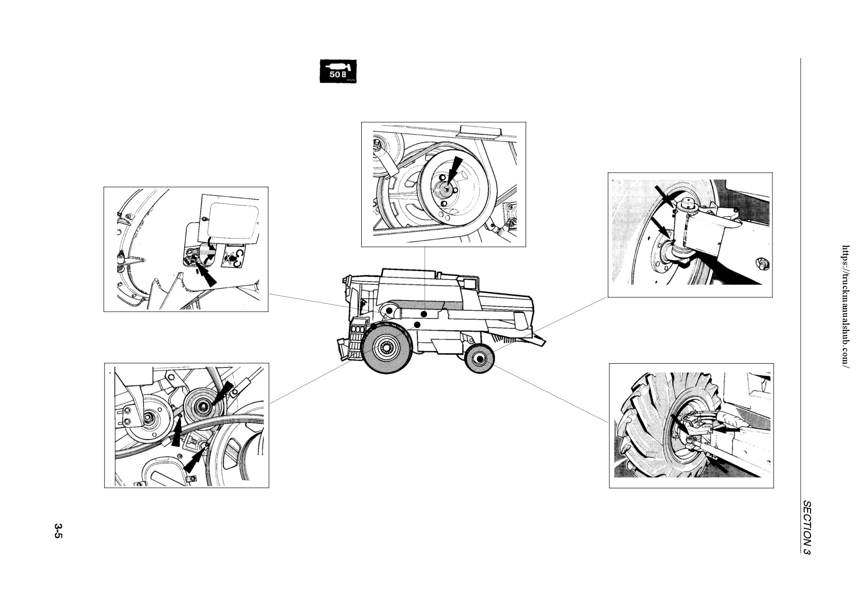
50 hour intervals -- Left-hand side (Cont’d)
Free pulley on beater shaft
Steering wheel spindle (2)
Unloading auger universal joint (2) +
sliding shaft (accessible through cover)
42788
17
20869
42786
18
21
Units with rear-wheel drive only:
Main engaging idler + pivot
Steering wheel spindle (2) +
Beater shaft bearing
tie rod ball joints
42782
20872
20
19
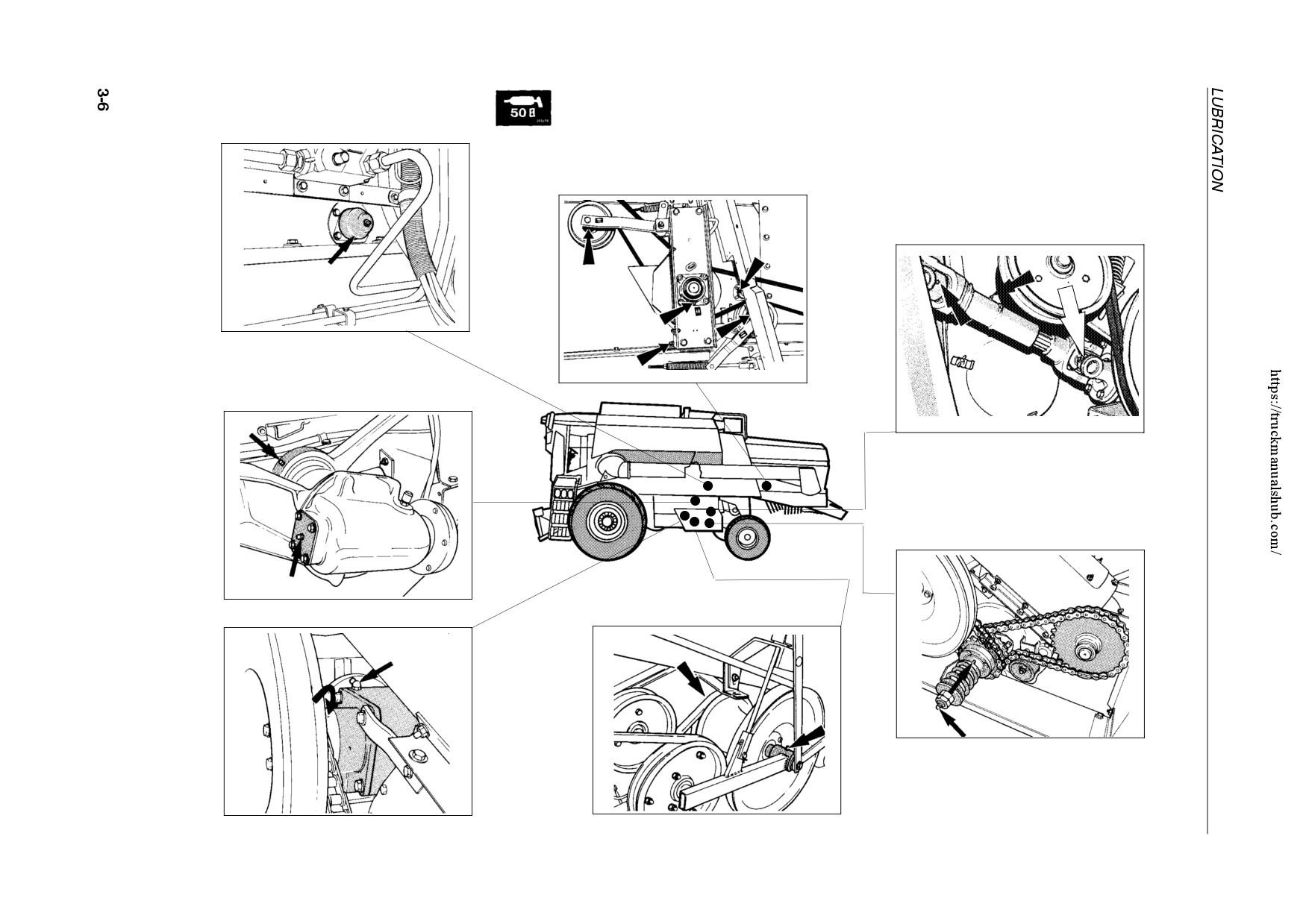
50 hour intervals -- Left-hand side (Cont’d)
Straw walker front shaft bearing
Straw walker rear shaft bearing
Straw chopper clutch bearings (2)
Straw chopper drive idlers (2)
Cleaning shoe drive U-joints (3)
[self-levelling cleaning shoe]
42781
22
Eccentric shaft bearing
55003
Cleaning shoe drive upper gearbox
23
[self-levelling cleaning shoe]
20882
24
Return drive slip clutch + bearing
42774
Cleaning shoe drive idler pivots (2)
28
Cleaning shoe drive idler arm pivot
[fixed cleaning shoe]
42795
25
42780
42945
27
26
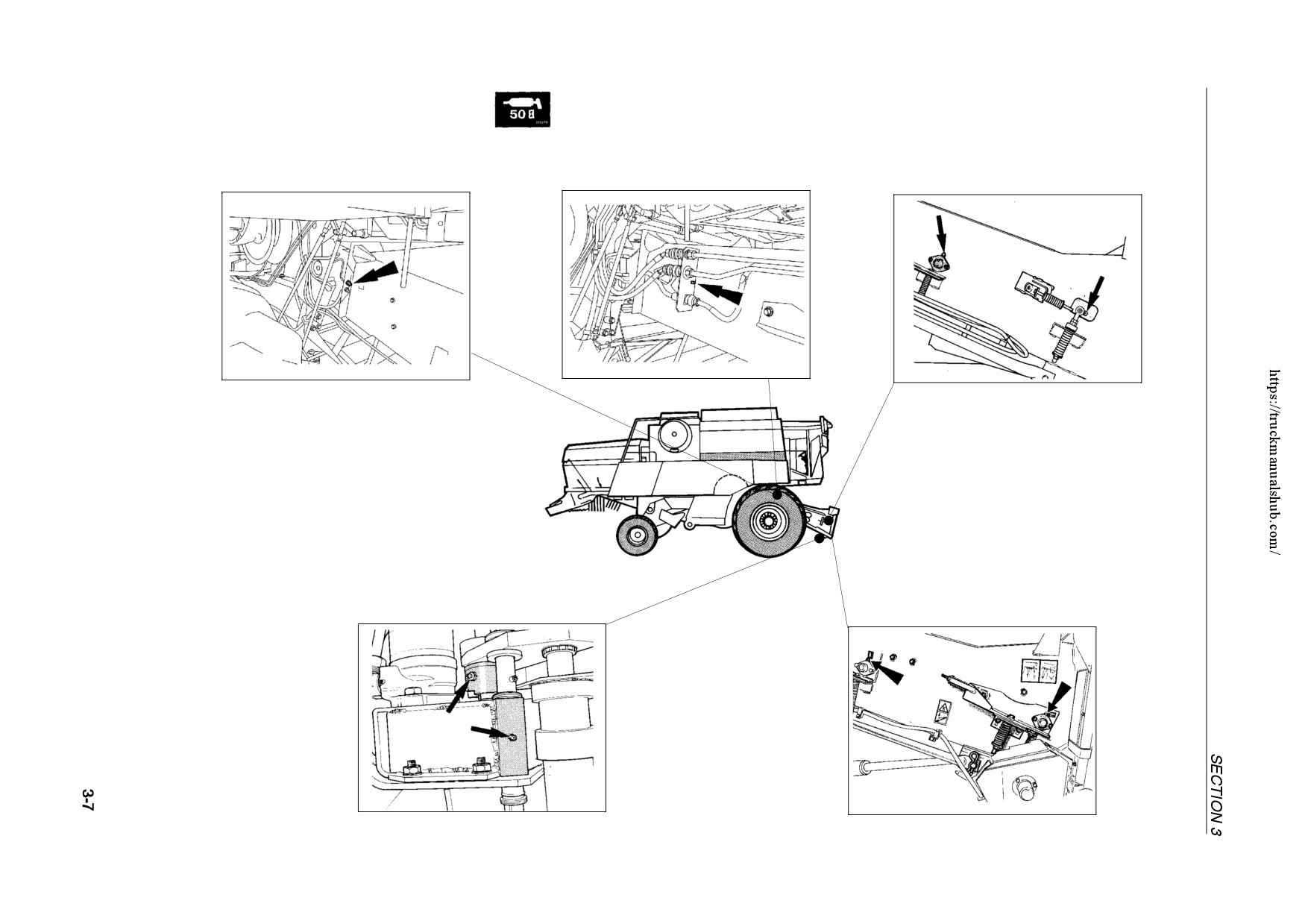
50 hour intervals -- Right-hand side
With lateral flotation:
Straw elevator upper shaft bearing
- Straw elevator front shaft bearing
(TX62 only)
Straw elevator upper shaft bearing
- Straw elevator middle shaft bearing
54722
54723
42802
29
30
31
Reversing mechanism (units with
hydraulic drive only)
Without lateral flotation:
- Guide shaft
- Straw elevator front shaft bearing
- Engaging jaw clutch
- Straw elevator middle shaft bearing
42789
55020
33
32
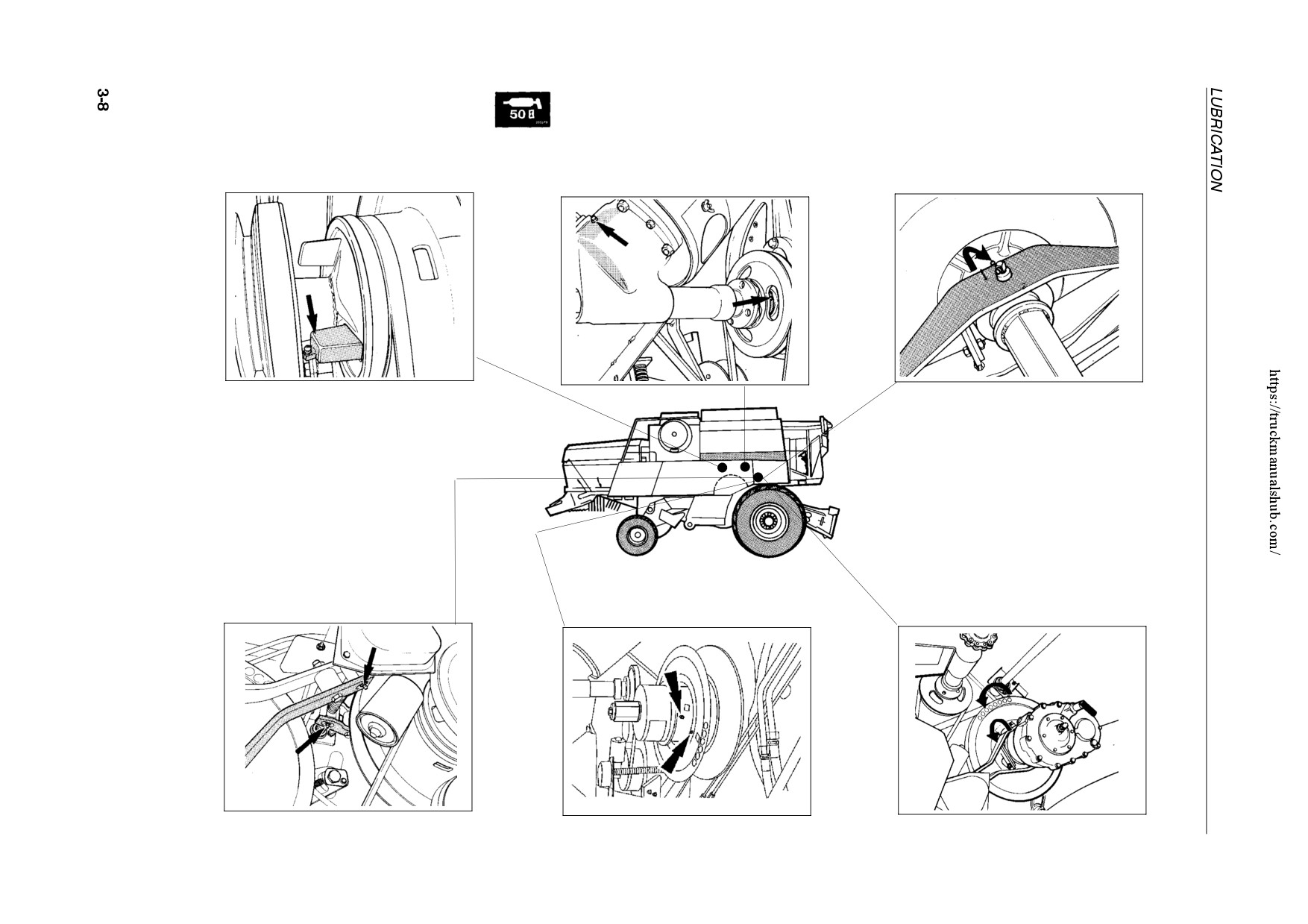
50 hour intervals -- Right-hand side (Cont’d)
Drum variator:
Grain tank filling system gearbox
Standard drum variator:
Floating disc on intermediate shaft
Grain tank filling system slip clutch
Floating disc on drum shaft
42794
42790
42777
34
36
35
Drum variator with speed reducer
[if installed]
Drum variator:
Drum variator (Positorque):
- Floating disc of drum speed reducer
Nut on threaded rods (2)
Floating disc on drum shaft
- Tapered bearing of drum speed reducer
42801
42969
23291
39
38
37
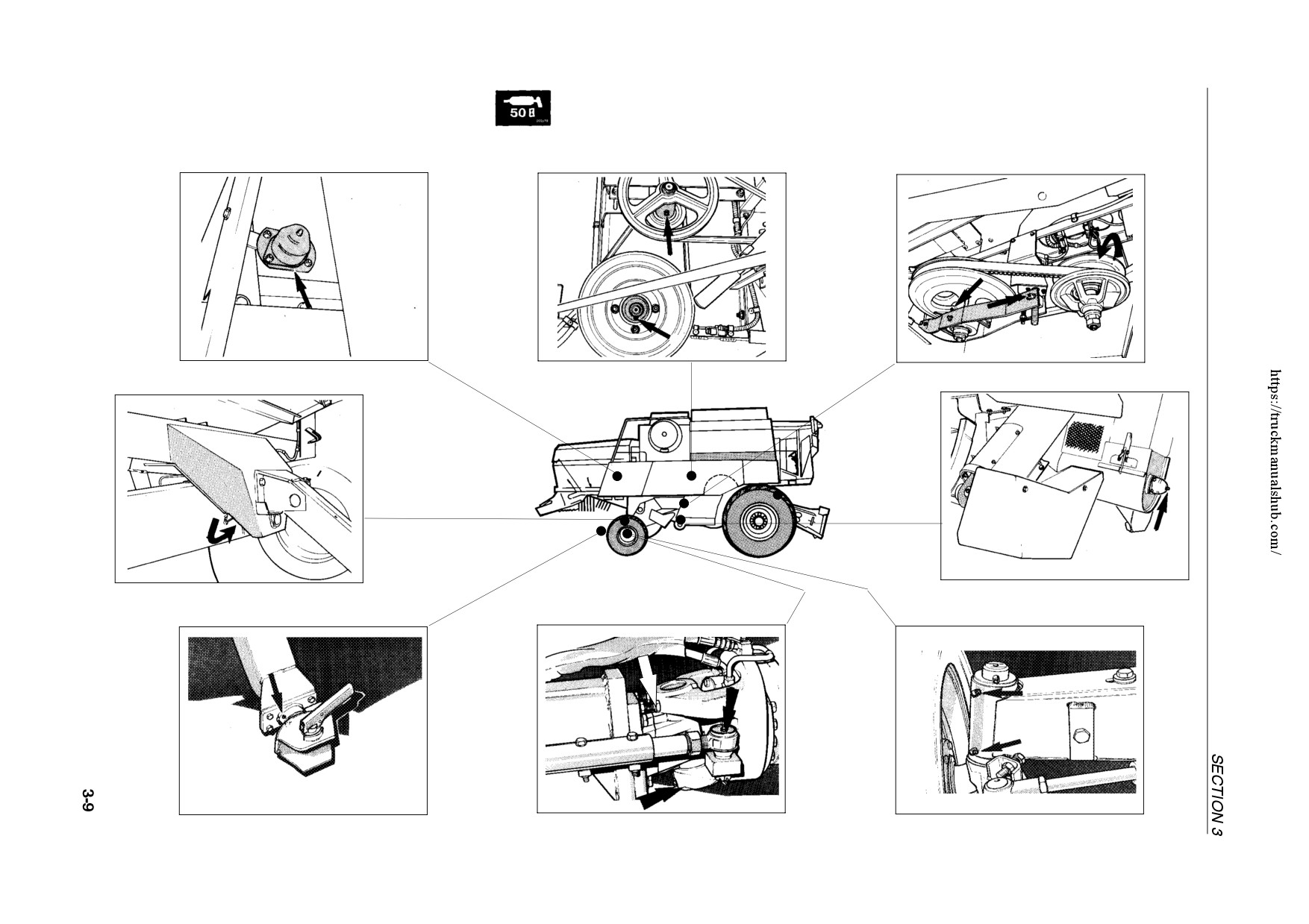
50 hour intervals -- Right-hand side (Cont’d)Eccentricshaftbearing
Fan variator:
- Floating disc on fan shaft
Straw walker front shaft bearing
- Floating disc on eccentric shaft
Straw walker rear shaft bearing
Straw walker intermediate shaft bearings
- Nut on threaded rods
42779
42792
42772
40
41
42
Steering axle pivot
Grain cross auger bearing
42793
42791
47
Units with rear-wheel drive only:
43
Trailer hitch [if installed]
Steering wheel spindle + ball joint (3)
Steering wheel spindle (2)
20882
20877
20887
46
45
44