New Holland TX62, TX63, TX64 Plus, TX65 Plus, TX66, TX67, TX68, TX68 Plus. Operator's Manual - page 1
OPERATOR’S MANUAL
TX62
TX63
TX64 Plus
TX65 Plus
TX66
TX67
TX68
TX68 Plus
Print No. 604.63.021.00
3rd edition
English 09/98
TABLE OF CONTENTS
Title
Page
Section 1 - Introduction
To the purchaser
1-1
Product identification
1-3
Important ecological considerations
1-7
Safety
1-8
Intended use
1-25
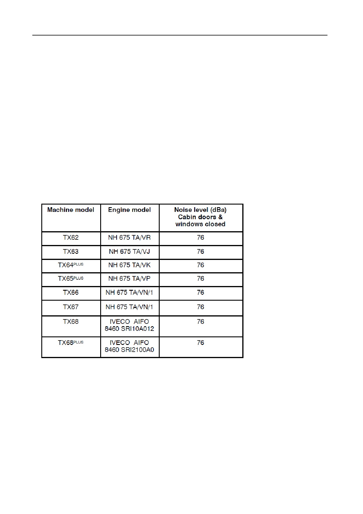
Airborne noise emission
1-26
Electromagnetic compatibility
1-27
Safety requirements for fluid power systems and components - Hydraulics
1-27
Vibration level information
1-28
Legal obligations
1-28
Section 2 - Operation
Machine function
2-1
Controls and instruments
2-5
Access to machine components
2-24
Before driving the combine
2-27
Starting the engine
2-27
Stopping the engine
2-29
Driving the combine
2-30
Header
2-34
Towing the combine
2-37
Wheels and tyres
2-37
Section 3 - Lubrication
Lubrication schedule
3-25
Section 4 - Field Operation
General information
4-1
Header
4-2
Straw elevator
4-18
Stone trap
4-24
Grain pan access
4-25
Antidust plate
4-26
Drum and concave
4-27
Beater
4-33
Rotary separator
4-36
Straw flow beater
4-36
Straw retarding curtain
4-37
Cleaning shoe
4-37
Sieves
4-38
Cleaning fan
4-41
Returns system
4-42
Grain tank
4-44
i
Unloading tube
4-48
Audible alarm
4-48
InfoView monitor
4-49
Speed control module
4-106
Differential lock
4-107
Straw chopper
4-107
Chaff spreader
4-112
Air conditioning
4-114
Combine performance checks
4-115
Grain loss measuring kit
4-117
Summary of machine settings for different crops
4-122
Section 5 - Adjustments and Maintenance
Drive belts and chains, left-hand side
5-1
Drive belts and chains, right-hand side
5-9
Straw elevator
5-22
Roto-threshers
5-24
Grain elevator
5-25
Brakes
5-26
Steering axle
5-29
Engine
5-41
Rotary dust screen and cooling system
5-48
Air intake system
5-49
Cab air filter
5-51
Air conditioning
5-52
Hydraulic system
5-55
Electrical system
5-56
Maintenance schedule
5-64
Section 6 - Troubleshooting
Feeding area
6-1
Threshing area
6-1
Threshing, separation and cleaning
6-3
General
6-7
Engine
6-8
Straw chopper
6-9
Powered rear axle
6-11
Hydraulic valve electrics -- Models TX62-63
6-12
Hydraulic valve electrics -- Models TX64PLUS-65PLUS-66-67-68-68PLUS
6-14
Gearshifting -- Model TX67
6-17
Remote parking brake -- Model TX67
6-18
Driving the combine after manual reset -- Model TX67
6-19
Section 7 - Storage
End-of-season service
7-1
Ordering Parts and/or Accessories
7-2
Preseason service
7-3
ii
Section 8 - Accessories
Section 9 - Specification
Wheels and tyres
9-1
Dimensions
9-9
Unloading tube position
9-10
Counterweights
9-12
Technical data
9-13
Section10 - Index
iii
SECTION QUICK REFERENCE
1 -- Introduction
2 -- Operation
3 -- Lubrication
4 -- Field Operation
5 -- Adjustments and Maintenance
6 -- Troubleshooting
7 -- Storage
8 -- Accessories
9 -- Specification
10 -- Index
SECTION 1
INTRODUCTION
TO THE PURCHASER
FOREWORD
This manual has been prepared to assist you in the
IMPORTANT:
correct procedure for operation, adjustment and
S
This machine has been designed and built
maintenance of your new machine.
according to the European Directive
EEC/89/392.
Always use genuine New Holland Service
This machine has been designed and built to give
Parts when servicing and repairing your
maximum performance, economy and ease of
machine and do not modify your machine
operation under a wide variety of crops and
without a written permission of the
conditions.
manufacturer. Failure to do so will void the
responsibility of the manufacturer.
Prior to delivery, your machine was carefully
inspected both at the factory and by your dealer to
S
An EC Declaration of Confirmity is
ensure that it reaches you in optimum condition.
separately delivered with your machine.
To maintain this condition and ensure trouble-free
Store this EC Declaration into the storage
operation it is important that routine services, as
space for your Operator’s Manual (Refer to
specified in this manual, are carried out at the
Section 2 - OPERATION).
recommended intervals.
S
The maximum road speed of your combine
You cannot operate or maintain your machine
is limited and sealed. Do not remove the
properly without reading this manual attentively. Keep
seal.
it within reach.
S
Check local road legislation before driving
the combine on public roads.
Before attempting to drive or operate your machine,
read this manuel carefully (especially the chapter
S
When operating interchangeable New
covering the Safety Precautions).
Holland built equipment, ensure the
equipment is CE approved.
‘‘Left’’ and ‘‘right’’ used throughout this manual are
determined from the rear, facing in the direction of
S
As this publication is distributed throughout
travel of the machine during operation.
our international network, the equipment
illustrated, either as standard or as an
If at any time you require advice concerning your
accessory, may vary according to the
machine, do not hesitate to contact your authorised
country in which the equipment is to be
dealer. He has factory-trained personnel, genuine
used. Low cost configurations, as chosen
service parts and the necessary equipment to carry
by the customer, may deviate from the
out your service requirements.
specifications given.
1-1
INTRODUCTION
S Several figures in this manual show the
We would like to point out that ‘‘nongenuine’’ parts and
safety guarding or the additional guards,
accessories have not been examined and released
legally required by certain countries, open
by the Company. The installation and/or use of such
or removed to illustrate better a particular
products could thus have negative effects upon the
feature or adjustment. The machine must
design characteristics of your machine and thereby
not be used in this condition. For your
affect its safety. The Company is not liable for any
own safety, ensure that all guards are
damage caused by the use of ‘‘nongenuine’’ parts and
closed or replaced before operating the
accessories.
machine.
Rely on your authorised dealer to supply you with
genuine service parts only. These parts are covered
by our warranty and will give you the best
IMPROVEMENTS AND CHANGES
performance.
The Company is continually striving to improve its
When ordering service parts, always quote the model
products, and therefore reserves the right to make
and serial number of your machine (refer to chapter
improvements and changes when it becomes
headed ‘‘Product identification’’.
practical and possible to do so, without incurring any
obligation to make changes or additions to the
equipment sold previously.
LUBRICANTS
Your dealer sells a selection of specially formulated
ACCESSORIES AND OPTIONS
lubricants based on own engineering specifications.
Your machine has been designed to operate in a wide
Recommended lubricants for your machine are listed
variety or crops and conditions. Nevertheless
on the inside rear cover of this manual.
additional equipment may, in certain cases, be
required to improve the machine performance. A list
of this additional equipment is given in Section 8 -
WARRANTY
ACCESSORIES in this manual.
Your machine is warranted according to legal rights in
your country and the contractual agreement with the
SERVICE PARTS AND ACCESSORIES
selling dealer. No warranty shall, however, apply if the
machine has not been used, adjusted and maintained
Genuine service parts and accessories have been
according to the instructions given in the Opertor’s
specifically designed for your machine.
Manual.
1-2
SECTION 1
PRODUCT IDENTIFICATION
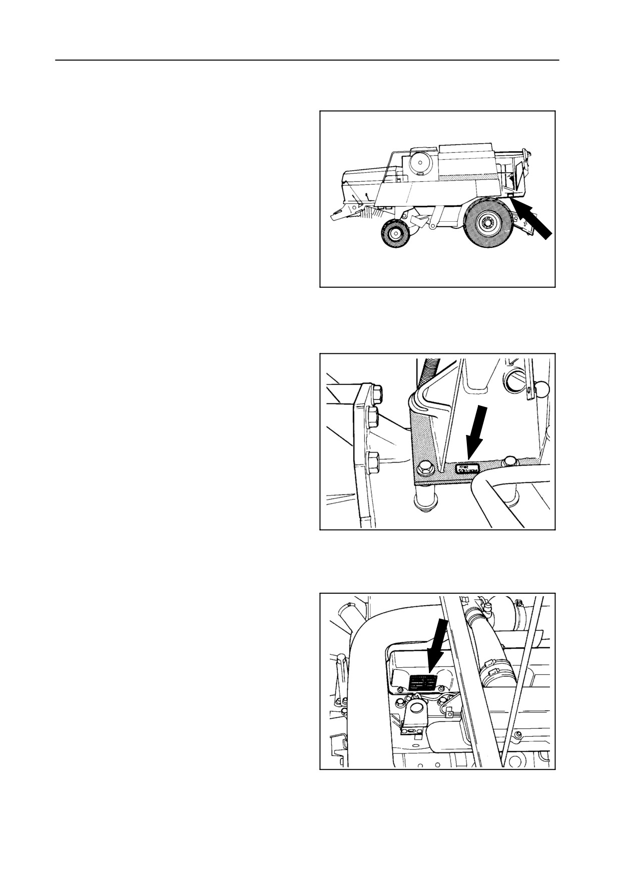
The serial numbers of the combine, engine and
attachments can be found in the following locations:
BASE UNIT -- Figures 1 and 2
On a plate positioned on the right-hand side of the
operator’s platform.
42767
1
On a plate positioned on the right-hand side of the
combine above the front axle.
42876
2
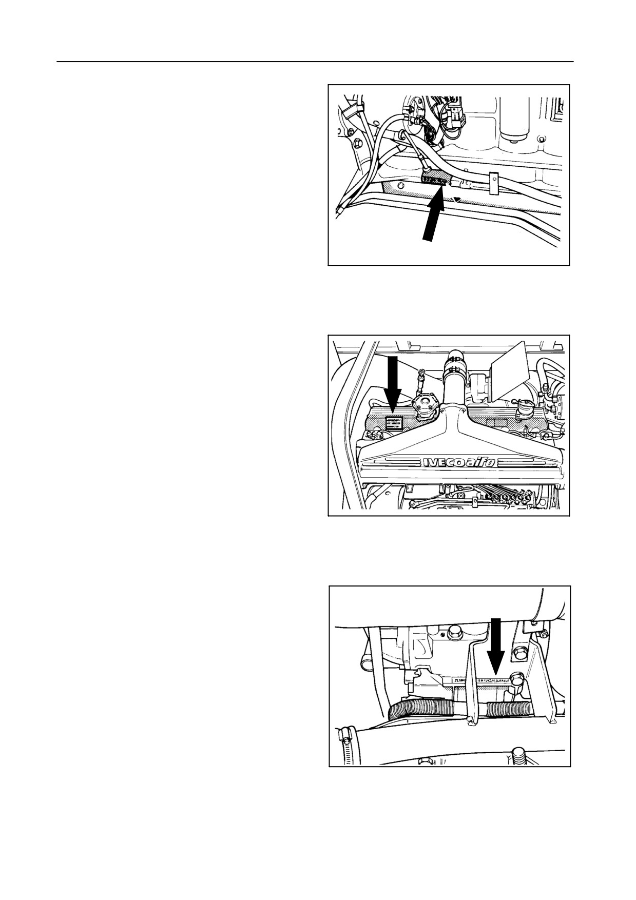
ENGINE
Models TX62-63-64PLUS-65PLUS-66-67 --
Figures 3 and 4
On a plate positioned on top of the rocker cover.
42973
3
1-3
INTRODUCTION
It is also stamped in the cylinder block.
42335
4
Model TX68-68PLUS -- Figures 5 and 6
On a plate positioned on top of the rocker cover.
42875
5
It is also stamped in the cylinder block.
42877
6
1-4
SECTION 1
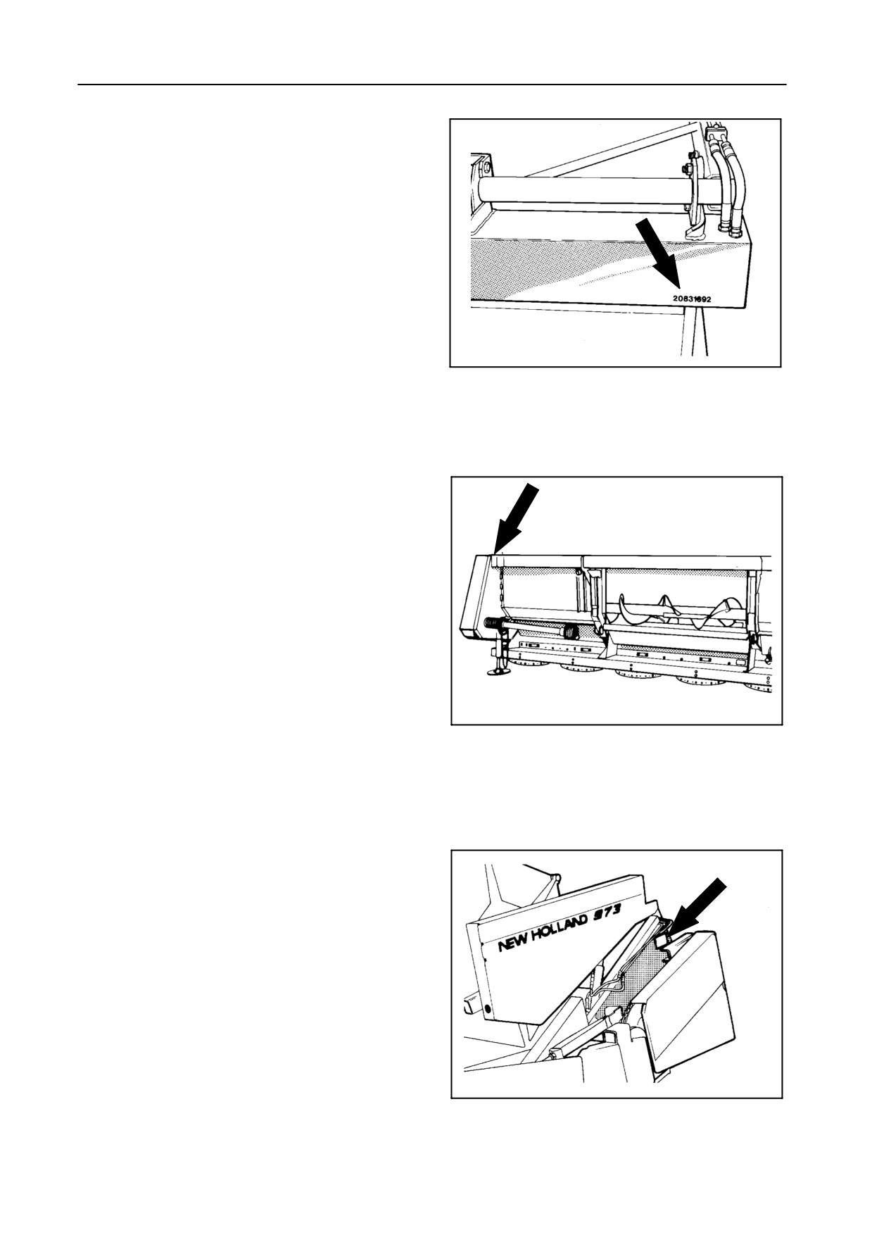
GRAIN HEADER -- Figure 7
In the right-hand upper corner of the header.
42724
7
MAIZE HEADER -- Figure 8
At the top of the left-hand corner.
42873
8
FLEX HEADER -- Figure 9
On the left rear corner of the main frame
43028
9
1-5
INTRODUCTION
Record below the serial numbers of your machine for quick
reference:
Combine model
Combine serial n°
Engine serial n°
Grain header serial n°
Maize header serial n°
Flex header serial n°
Date machine first used
Dealer’s telephone n°
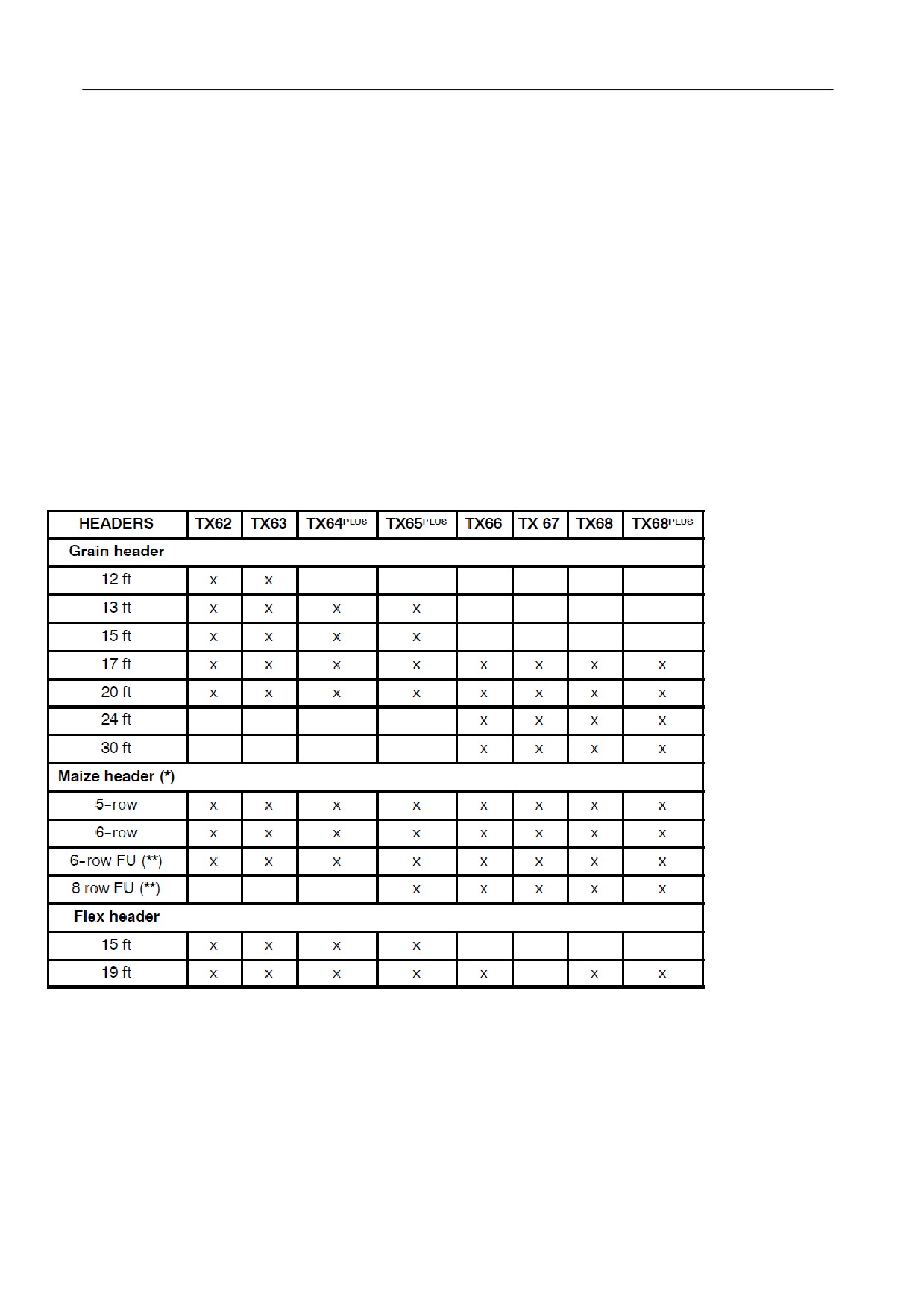
HEADER INFORMATION
The model TX combines can be equipped with the following headers:
(*) Available with a) Knife stalk rolls or smooth stalk rolls
b) Row distances: 70 cm - 75 cm - 80 cm
c) Stalk chopper
(**) Flip-up
1-6
SECTION 1
IMPORTANT ECOLOGICAL CONSIDERATIONS
Soil, air and water are vital factors of agriculture and
oils, brake fluids, etc. Do not mix drained brake
of life in general. Where legislation does not yet rule
fluids or fuels with lubricants. Store them safely
the treatment of some of the substances which are
until they can be disposed of in a proper way to
required by advanced technology, common sense
comply with local legislation and available
should govern the use and the disposal of the
resources.
products of a chemical and a petrochemical nature.
6. Modern coolant mixtures, i.e. antifreeze and
The following are recommendations which may be of
other additives, should be replaced every two
assistance:
years. They should not be allowed to get into the
soil but should be collected and disposed of
safely.
S Become acquainted with and respect the relative
legislation applicable in your country.
7. Do not open the air-conditioning system yourself;
S Where no legislation exists, obtain information
it contains gases which should not be released
from suppliers of oils, fuels, antifreeze, cleaning
into the air. Your dealer has a special extractor for
agents, etc. for their effect on man and nature and
this purpose and will have to do the recharging of
for safe ways of storage, usage and disposal.
the system anyway.
Agricultural consultants will, in many cases, be
able to help you as well.
8. Repair any leaks or defects in the engine cooling
or the hydraulic system immediately.
Helpful hints:
9. Do not increase the pressure in a pressurized
1. Avoid filling fuel tanks using jerrycans or
circuit as this may lead to bursting of the
inappropriate pressurized fuel delivery systems
components.
which may cause considerable spillage.
10. Protect hoses during welding as penetrating weld
2. In general, avoid skin contact with all fuels, oils,
splatter may burn a hole or weaken them, causing
acids, solvents, etc. Most of them contain
the loss of oils, coolant, etc.
substances which can be harmful to your health.
11.
Battery recycling
3. Use bio-degradable oils for chain lubrication
where oils cannot be recuperated. In many
Batteries and electric accumulators contain
countries rape seed oils or other agro-based
various components which can damage the
lubricants have become available.
environment if they are not properly recycled
after usage. New Holland strongly recommends
4. Modern oils contain additives. Do not burn
that you return all used batteries
(starting
contaminated fuels and/or waste oils in ordinary
batteries and small ‘‘dry’’ batteries which may be
heating systems.
used in electric or electronic systems) to your
New Holland dealer who will ensure proper
5. Avoid spillage when draining off used engine
disposal or re-cycling. In certain countries this is
coolant mixtures, engine, gearbox and hydraulic
a legal requirement.
1-7
INTRODUCTION
SAFETY
Farm accidents can be prevented with your help
CAUTION:
No accident prevention programme can be
The word “CAUTION” is used where a
successful without the wholehearted cooperation of
safe behavioural practice according to
the person who is directly responsible for the
operating and maintenance instructions
operation of the equipment.
and common safety practices will protect
To read of accident reports from all over the country is
the operator and others from accident
to be convinced that a large number of accidents can
involvement.
be prevented only by the operator anticipating the
result before the accident is caused and doing
something about it.
It is said that “The best kind of safety device is a
WARNING:
careful operator who with care and mature
The word
“WARNING’’ denotes a
consideration can save more lives and limbs than any
potential or hidden hazard which could
accident prevention programme which is not adhered
possibly cause serious injury. It is used
to”.
to warn operators and others to excercise
Further in this chapter you will find a list of the most
due care and attention to avoid a surprise
important safety precautions.
accident with machinery
CAUTION:
DANGER:
S This symbol is used throughout this
The word
“DANGER” denotes a
manual whenever your personal
forbidden practice in connection with a
safety is involved.
serious hazard.
TAKE TIME TO READ AND FOLLOW
THE
INSTRUCTIONS
AND
FAILURE TO FOLLOW THE
‘‘CAUTION”,
FURTHERMORE, BE CAREFUL!
‘‘WARNING”, AND ‘‘DANGER” INSTRUCTIONS
MAY RESULT IN SERIOUS BODILY INJURY OR
S Some pictures in this manual may
DEATH.
show the safety guarding open or
removed to better illustrate a
particular feature or adjustment.
ENSURE TO CLOSE OR REPLACE
ALL GUARDS BEFORE OPERATING
Machine safety
THE MACHINE.
Additional precautionary statements (“ATTENTION”
and
“IMPORTANT”) are followed by specific
instructions. These statements are intended for
machine safety.
PRECAUTIONARY STATEMENTS
ATTENTION:
The word “ATTENTION” is used to warn the operator
Personal safety
of potential machine damage if a certain procedure is
not followed.
Throughout this manual and on machine decals, you
will find precautionary statements
(“CAUTION”,
IMPORTANT:
“WARNING”, and “DANGER”) followed by specific
The word “IMPORTANT” is used to inform the reader
instructions. These precautions are intended for the
of something he needs to know to prevent minor
personal safety of you and those working with you.
machine damage if a certain procedure is not
Please take the time to read them.
followed.
1-8
SECTION 1
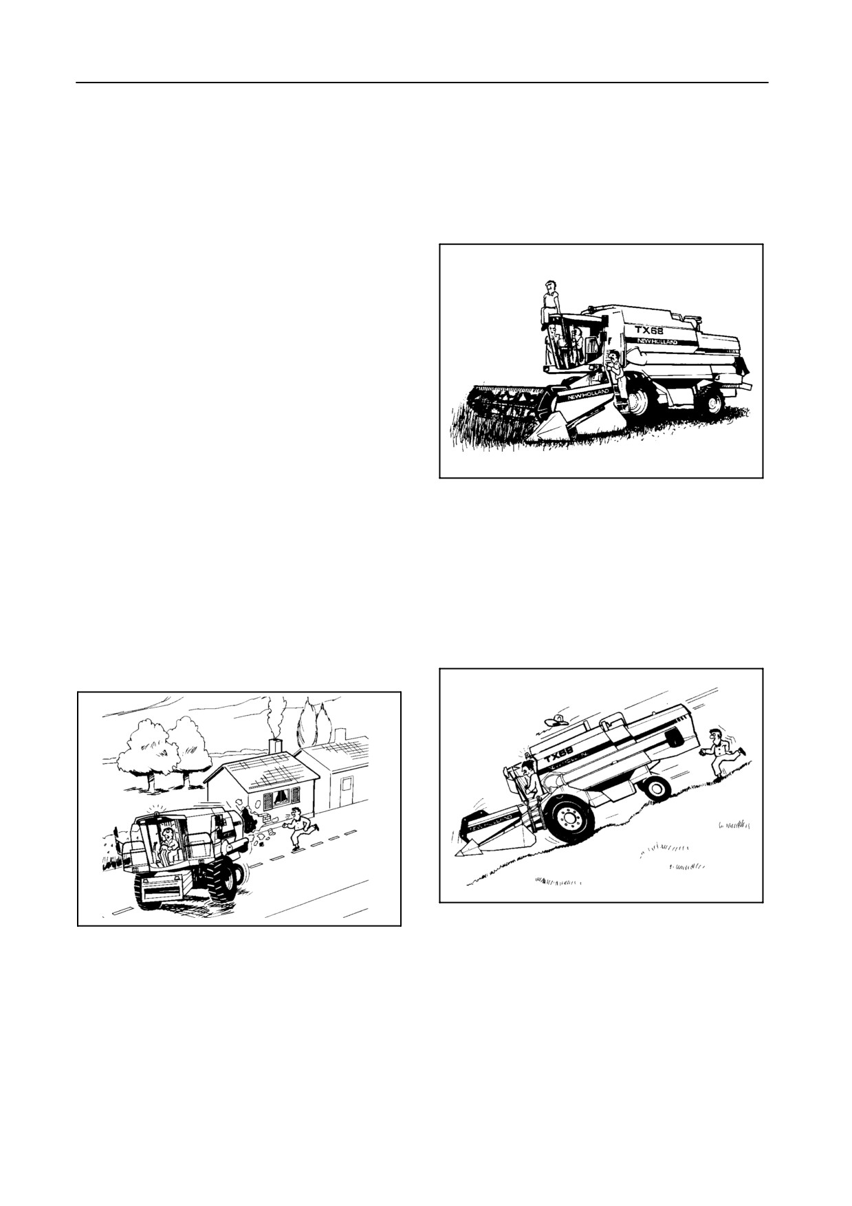
SAFETY PRECAUTIONS
5.
Raise and lock the ladders when travelling on
public roads. No-one should be standing on the
ladders when the machine is moving.
Most farm machinery accidents can be avoided by the
observance of a few simple safety precautions.
6.
Do not permit anyone other than the operator to
ride on the combine.
General and Operating Safety
1. The machine must only be used by a skilled
operator familiar with all the controls and
harvesting techniques on cultivated land with
slopes up to maximum 26% (15°) uphill and
downhill, and maximum 36% (19°) sideways
[provided good even ground and sufficient tyre
adherence conditions exist].
2. When driving on public roads, observe traffic
regulations, adapt your speed to road and traffic
52031
conditions and ensure that all lights and other
safety mechanisms on the machine (if they are
required) are fitted and work properly.
7.
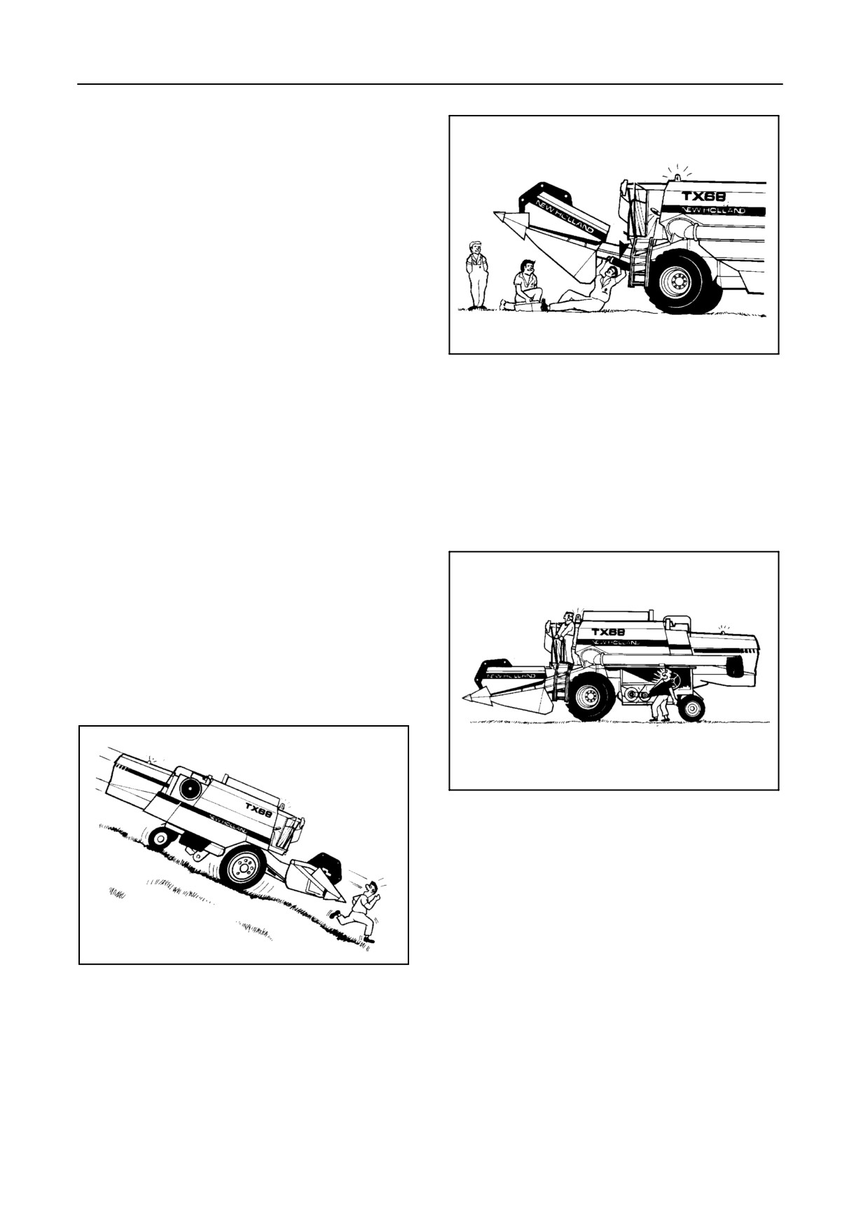
Do not brake abruptly to avoid tipping of the
The grain tank must be empty when driving on
machine.
the road. Ensure that the unloading tube is
locked in its closed position.
8.
Do not exceed 20 km/h when driving downhill. If
necessary, change into a lower gear before
3. Ensure that both brake pedals are locked
starting the descent.
together when travelling on public roads.
52032
52030
9. Before operating the combine ensure that all
safety guards are installed.
4. Ensure the hazard warning signs provided are
installed at the front and the rear of the combine
10. Before starting the engine, ensure everyone is
and use the rotating amber traffic warning
clear of the combine.
beacon(s) when driving on public roads to
indicate the vehicle is of abnormal size and is
Warn bystanders by sounding the horn several
slow-moving.
times.
1-9
INTRODUCTION
11. Keep children away from and off the combine at
all times.
12. Check the wheel nuts torque as described in
Section
5
--
ADJUSTMENTS AND
MAINTENANCE.
13. Do not enter the grain tank while the combine
52034
engine is running. Use a wooden clearing club
should the grain tank unloading auger become
clogged. Take utmost care not to be pulled into
the grain tank in case unplugging is required.
17. Do not work around the combine in loose
clothing that might catch in any of the moving
14. Do not attempt to clean, lubricate or carry out
parts.
any adjustments on the combine while it is in
motion or while the engine is running.
15. For safety’s sake never leave the operator’s
platform without first disengaging the combine
drive mechanism, lowering the header, stopping
the engine, applying the handbrake and
removing the ignition key.
52035
18. Keep hands away from moving parts of the
combine.
52033
19. Keep the fire extinguisher within easy reach of
the operator. Ensure to replace it by a similar
type of extinguisher or have it checked or refilled
after every usage and/or date of expiry.
16. Do not work under the combine header unless it
is securely blocked and/or the header safety
20. Do not step on the grain tank covers or the cab
latch is engaged.
roof.
1-10
SECTION 1
21. When driving on public roads, either with the
Engine
grain header loaded on a trailer and attached to
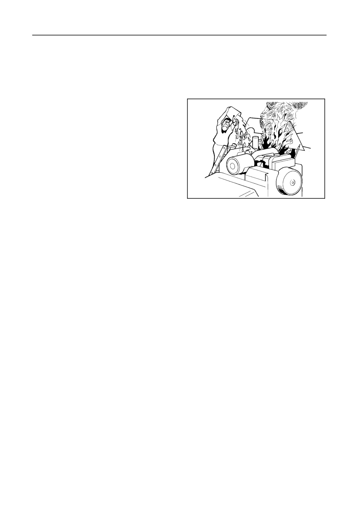
1. Keep the engine area clean of dust, chaff and
the rear of the combine, or with the grain header
straw to prevent the possibility of fires.
still attached to the combine
(provided local
legislation allows), the knife should be
safeguarded by means of a knife guard,
available as an accessory (refer to the Grain
Header Operator’s Manual).
22.
Combine dust can cause
‘‘farmer’s lung’’
disease. It may also contain nocive spraying
residues. Keep the cab door and window closed
during operation. Wear a dust mask when
cleaning the air filters or accumulated dust in the
combine.
52036
23.
Danger of death by electrocution!
Pay special attention to the overhead power
lines. Make sure the machine has sufficient
clearance to pass in all directions (also with
raised or opened machine components). Also
2.
Never idle the engine in an enclosed area as
think of the radio aerial(s) or any other factory-
harmful exhaust gases may build up.
fitted accessory or parts which may have been
added afterwards.
3.
Wear a suitable hearing protective device, such
Should a contact between the machine and an
as ear muffs or ear plugs, if you are exposed to
electric power line occur, then the following
noise which you feel is uncomfortable.
precautions must be taken: Stop the machine
movement immediately, stop the engine and
apply the handbrake.
4.
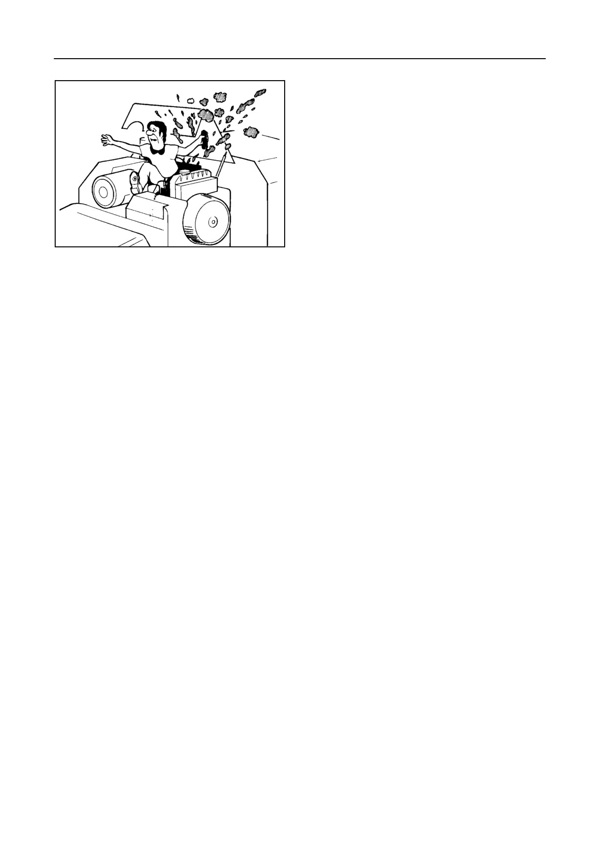
The cooling system operates under pressure
which is controlled by the radiator cap. It is
Check if you can safely leave the cab or your
dangerous to remove the cap while the engine is
actual position without direct contact with
hot.
electric wires. If not, stay in your position and call
for help. If you can leave your position without
touching the lines, jump off the last step or
S Switch off the engine and wait until it has
support position to ensure that there is no
cooled. Even then use extreme care when
contact between any part of your body and the
removing the cap. Cover the cap with a rag
ground at any time. Do not touch the machine
and turn it slowly to the first stop to allow the
afterwards until power to the lines has been shut
pressure to escape before removing the cap
off. When people approach the machine, warn
completely. Stand clear of the radiator
them not to touch the machine but to ask the
opening as hot coolant may splash out.
electric power supply company to shut off the
power to the lines.
S Never add cold water to a hot radiator.
1-11
INTRODUCTION
8. Do not handle a hot oil filter with bare hands.
9. Continuous and prolonged contact with used
engine oil may cause skin cancer. Protect your
skin by wearing heavy plastic gloves. If oil gets
onto the skin, wash promptly with soap and
water.
Diesel fuel
52037
1.
Under no circumstances should gasoline,
alcohol or blended fuels be added to diesel fuel.
These combinations can create an increased
fire or explosive hazard. In a closed container,
Failure to follow these instructions may result in
such as a fuel tank, such blends are more
serious personal injury from hot coolant or steam
explosive than pure gasoline. Do not use these
blowout and/or damage to the cooling system or
blends.
engine.
2.
Never remove the fuel tank cap or refuel with the
5.
Antifreeze contains monoethylene glycol and
engine running or hot.
other chemicals which are toxic if taken
Refuel the harvester only when the engine has
internally and can be absorbed in toxic amounts
been turned off.
through repeated or prolonged skin contact.
Do not smoke or use a naked flame when
Follow these precautions when working with
refuelling or when standing near fuel tanks.
antifreeze:
3.
Maintain control of the fuel filter pipe nozzle
S Do not take antifreeze internally. If antifreeze
when filling the tank.
is swallowed accidentally, obtain medical
attention immediately.
4.
Do not fill the fuel tank to capacity. Allow room for
expansion.
S Keep antifreeze in sealed containers out of
reach of children, livestock or pets.
5.
Wipe up spilled fuel immediately.
6.
The fuel oil in the injection system is under high
6.
Always tighten the fuel tank cap securely.
pressure and can penetrate the skin. Unqualified
persons should not remove or attempt to adjust a
fuel injection pump, injector, nozzle or any other
7.
If the original fuel tank cap is lost, replace it with
part of the fuel injection system. Failure to follow
an approved cap. A nonapproved, proprietary
these instructions may result in serious injury.
cap may not be safe.
If fuel is injected through the skin, medical
assistance should be obtained.
8.
Keep equipment clean and properly maintained.
7.
Be very careful to avoid contact with hot engine
9.
Do not drive equipment near open fires.
oil. If the engine oil is extremely hot, allow the oil
to cool to a moderately warm temperature for
safe removal.
10.
Never use fuel for cleaning purposes.
1-12
SECTION 1
BATTERY WARNING
S Wear eye protection when working
near batteries.
CAUTION:
S Provide ventilation when charging or
The battery contains a sulphuric acid
using in an enclosed space.
electrolyte which may cause severe
burns and produce explosive gases.
S Ensure the vent plugs are correctly
Avoid contact with the skin, eyes or
installed and tight.
clothing. Do not take internally.
The essential precautions listed below
must be observed:
If the electrolyte comes into contact with the skin,
S Do not use a naked flame to check the
eyes or is taken internally, treat as follows:
electrolyte level. Keep sparks, flames
and lighted tobacco away.
Skin:
Flush with cold water.
S Do not produce sparks with cable
clamps when charging the battery or
Eyes:
Flush with cold water for 10 minutes and get
starting the engine with a slave
prompt medical attention.
battery.
Internal: Call a doctor immediately.
1-13
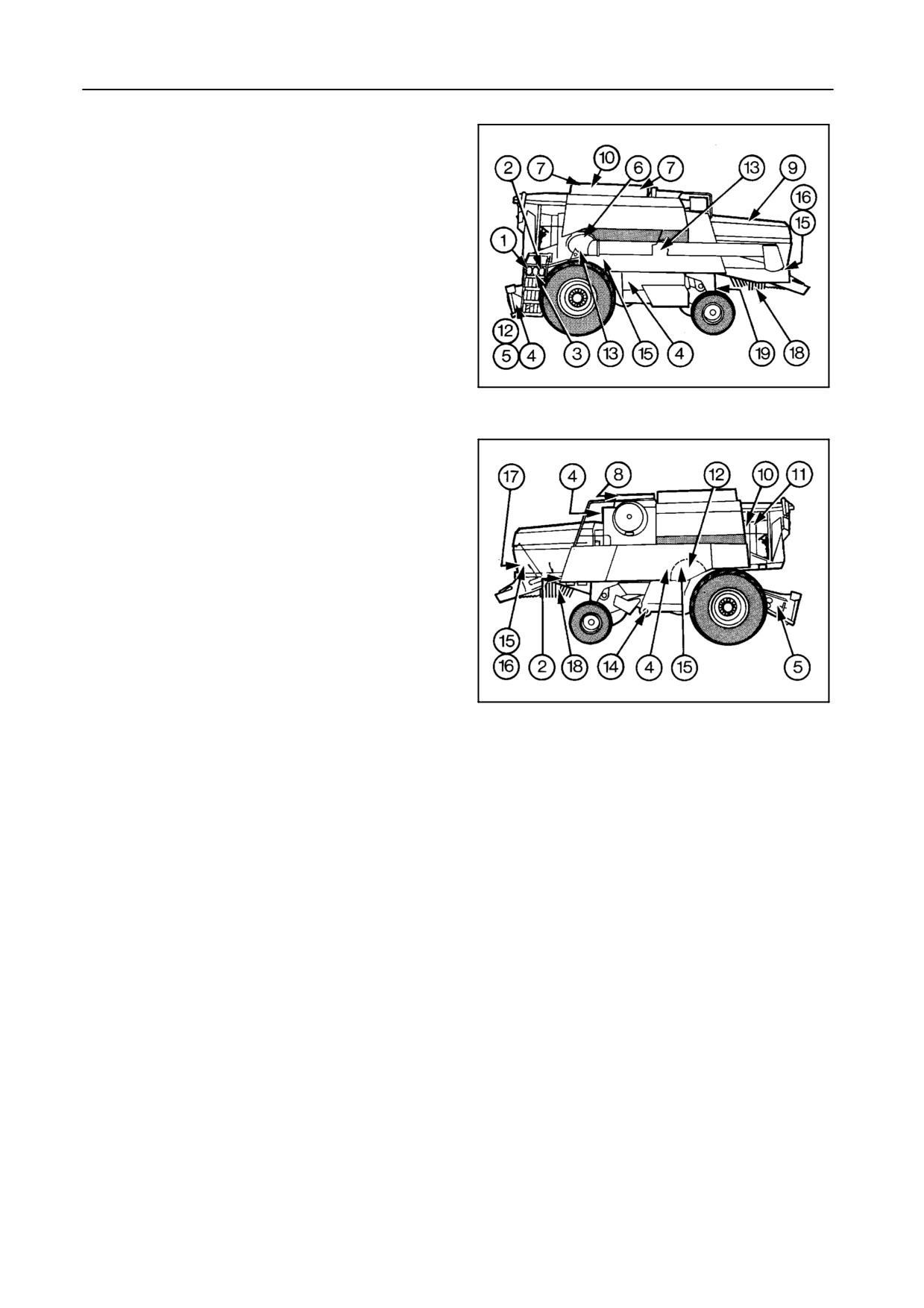
INTRODUCTION
SAFETY DECALS
The following safety decals have been placed on your
machine in the areas indicated. They are intended for
the personal safety of you and those working with
you.
Please take this manual, walk around your machine
and note the content and location of these warning
signs.
Review these decals and the operating instructions in
this manual with your machine operators.
55075
Keep the decals legible. If they are not, obtain
10
replacements from your dealer.
55095
11
1-14
SECTION 1
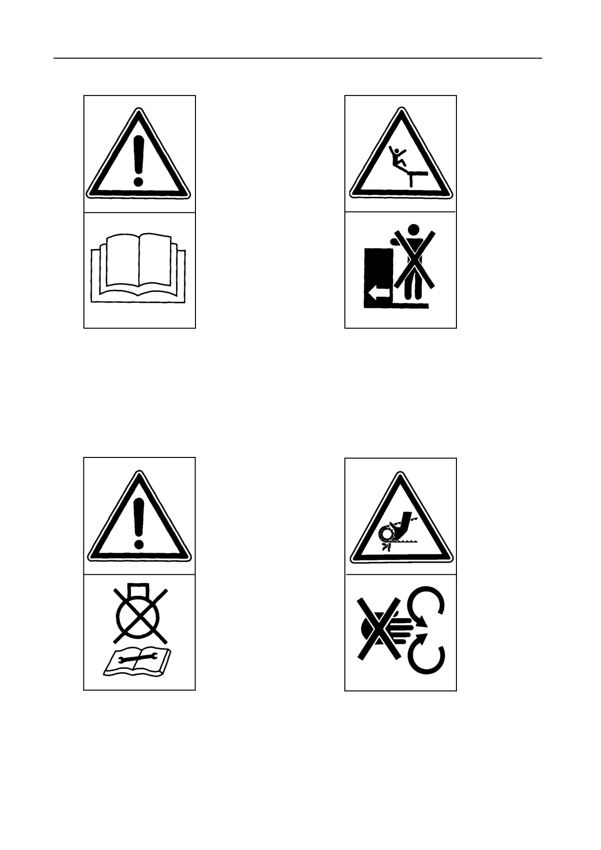
Decal 1
Decal 2
Carefully read the Operator’s Manual before oper-
Do not ride on platform or ladder.
ating the machine. Observe instructions and safe-
ty rules when operating.
Decal 3
Decal 4
Disengage all drives, stop the engine and wait un-
Do not open or remove safety shield while engine
til moving parts have stopped before cleaning or
is running.
servicing the machine.
1-15
INTRODUCTION
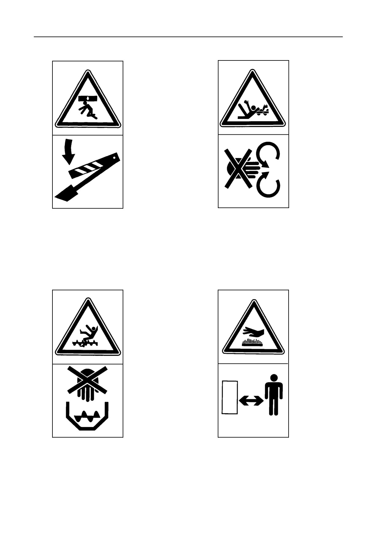
Decal 5
Decal 6
Secure lift cylinder with locking device before getting
Never reach into rotating auger.
in dangerous area.
Decal 7
Decal 8
Never reach nor climb into grain tank while engine is
Stay clear of hot surface.
running.
1-16
SECTION 1
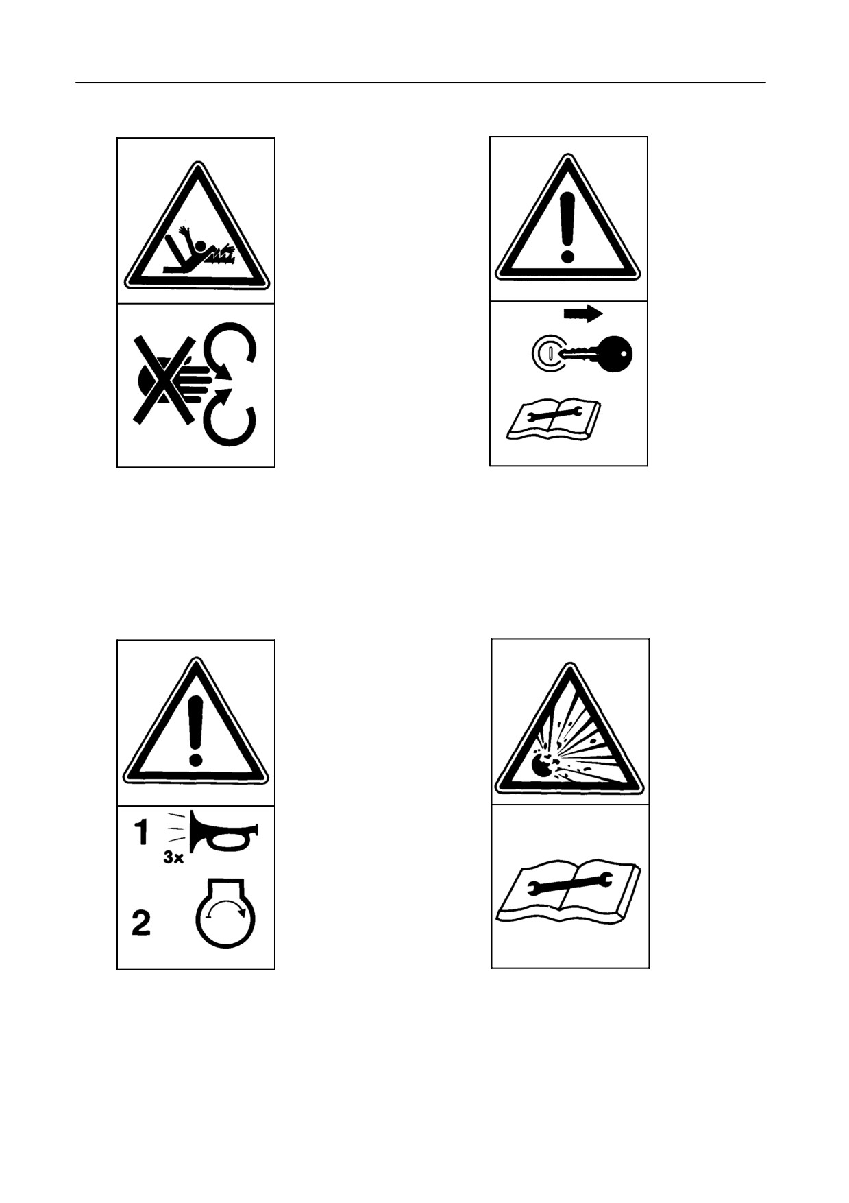
Decal 9
Decal 10
Do not reach into straw walkers while engine is run-
Shut off engine and remove ignition key before
ning.
performing maintenance or repair work.
Decal 11
Decal 12
Sound the horn 3 times before starting the engine.
Hydraulic accumulator contains gas and oil under
pressure. For removal and repair, contact your lo-
cal New Holland dealer.
1-17
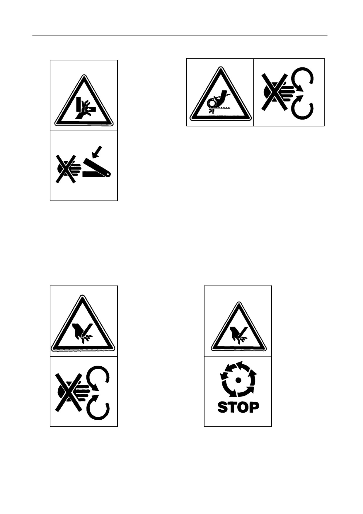
INTRODUCTION
Decal 13
Decal 14
Do not open or remove safety guard while engine is
running.
Never reach into the crushing danger area as long
as parts may move.
Decal 15
Decal 16
DANGER:
Wait until all machine components have stopped
Stay clear of rotating machine parts.
completely before touching them.
1-18
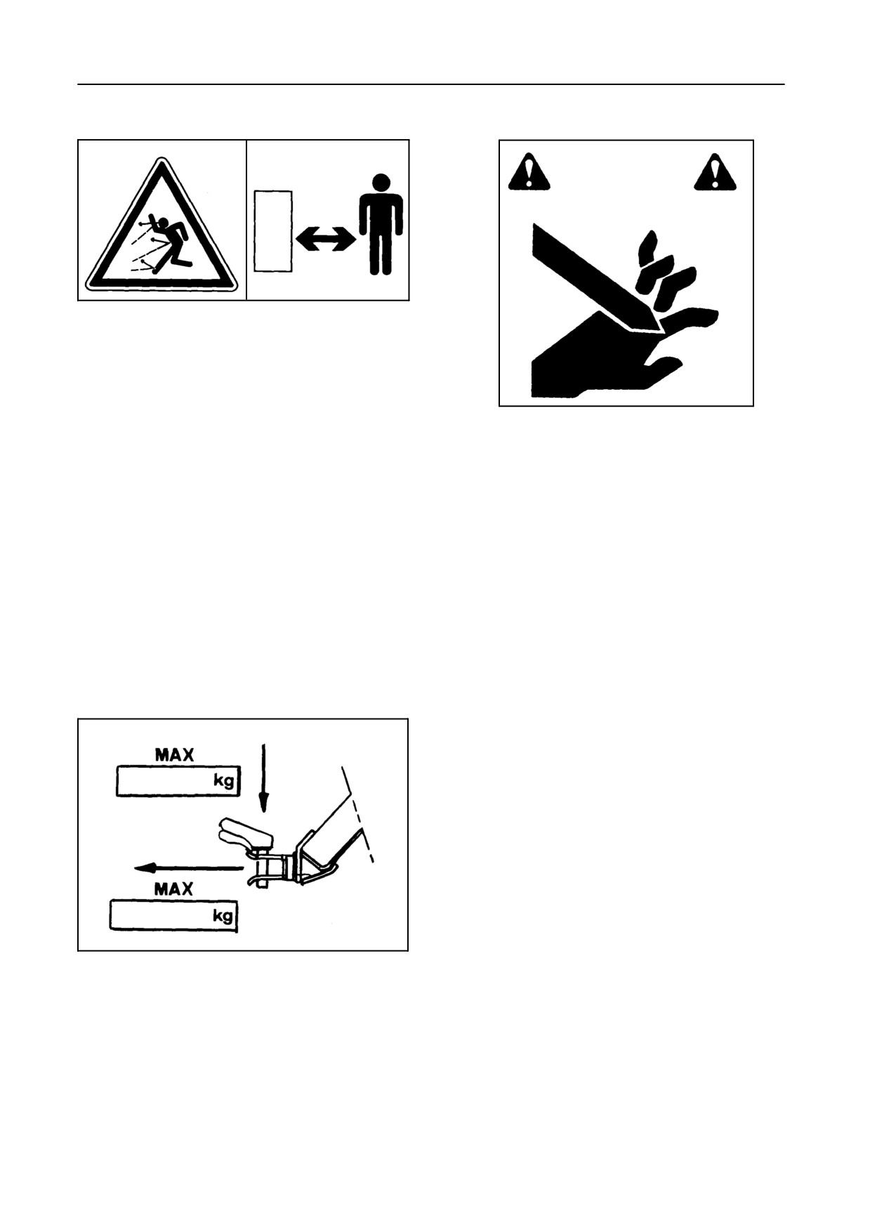
SECTION 1
Decal 17
Decal 18
DANGER:
Stay clear while engine is running.
DANGER:
Stay clear while engine is running.
Decal 19
51894
This plate indicates:
1. The maximum allowed vertical force.
2. The maximum allowed horizontal pull force of
the hitch.
1-19
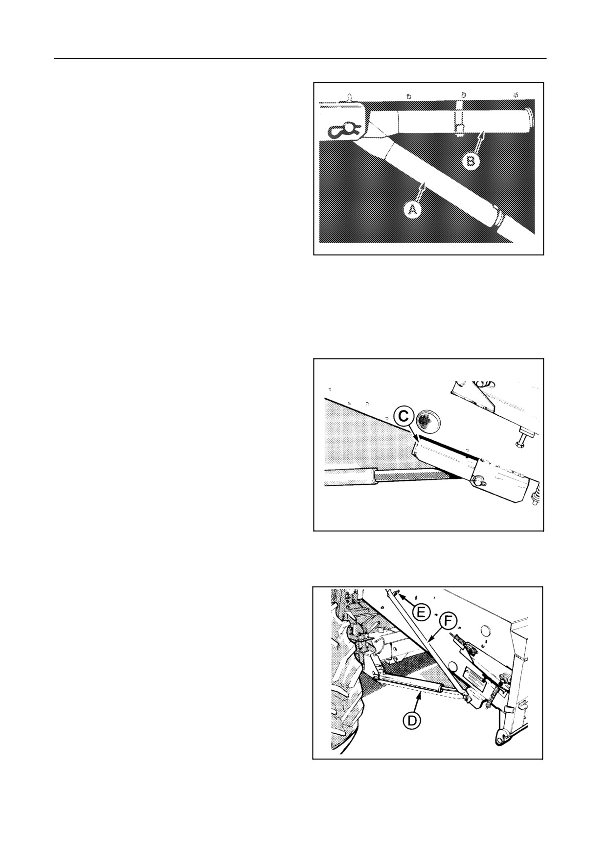
INTRODUCTION
PROTECTIVE DEVICES
Header standard safety latch -- Figure 12
The left-hand header cylinder is standard fitted with a
safety latch which must be lowered onto the cylinder
rod to prevent accidental lowering of the header.
Whenever work is carried out underneath the header,
the latch must be lowered onto the cylinder rod as
shown at A.
When not in use the header safety latch must be
20259
stored as shown at B.
12
ATTENTION:
Do not use the safety latch A as a support for
the header when travelling along public roads
otherwise damage may occur to the cylinder.
Header additional safety latch -- Figure 13
For certain countries a small safety latch C is fitted
onto the right-hand cylinder. It must be lowered onto
the cylinder rod when driving on public roads to
prevent accidental lowering of the straw elevator.
When a flip-up maize header is attached to the straw
elevator, a special safety latch (provided with the
machine) must be installed and lowered onto the
cylinder rod when driving on public roads.
21108
13
Straw elevator additional support -- Figure 14
For certain countries there is a legal obligation to have
an additional support F installed on the right-hand
side of the straw elevator. This support must be
placed in position D whenever the machine is driven
on public roads.
When not in use, support F can be stored in bracket E.
When a maize header is attached to the straw
elevator, a special support F
(provided with the
machine) must be installed and used when driving on
21106
public roads.
14
1-20
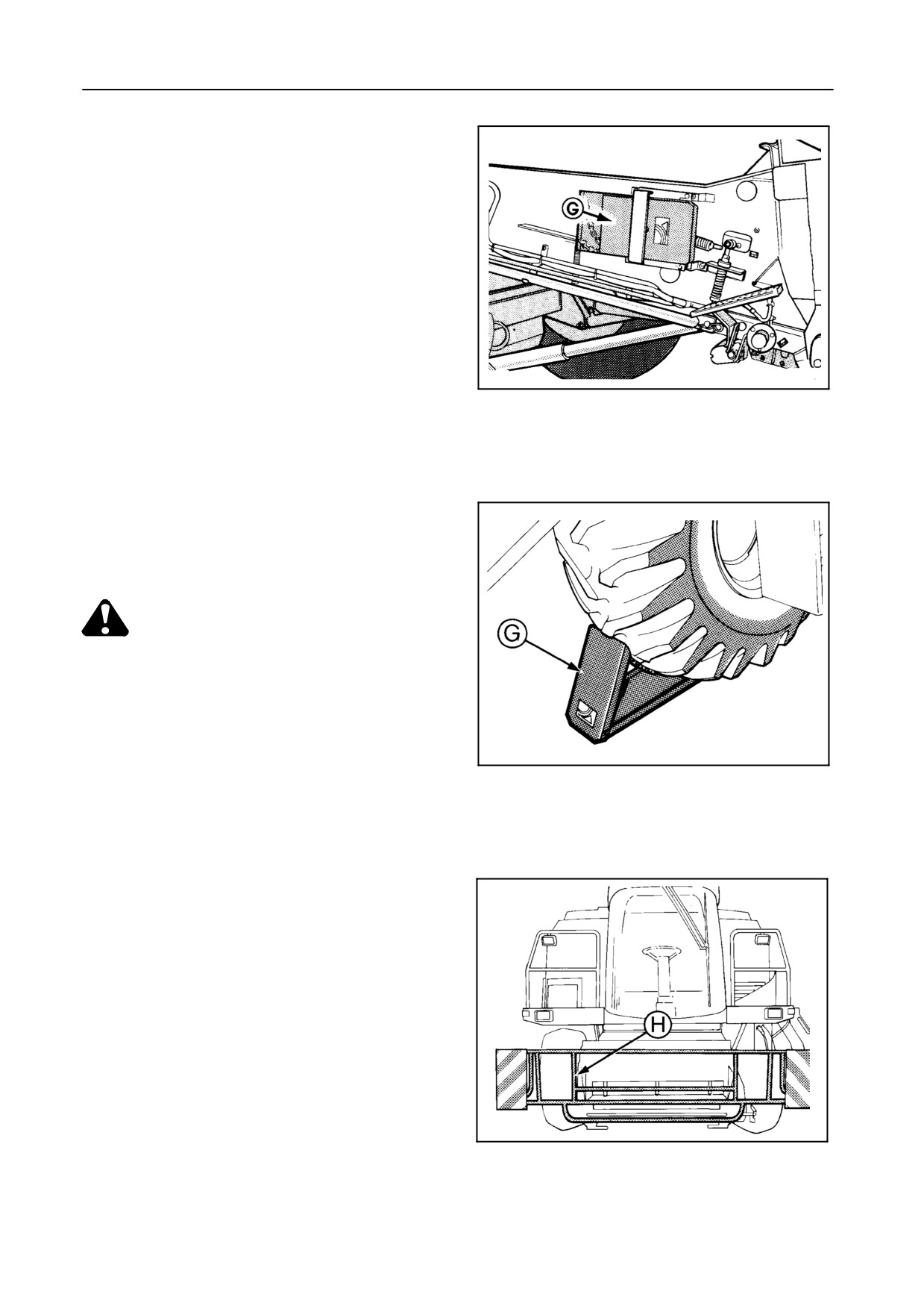
SECTION 1
Wheel chock -- Figures 15 and 16
For some countries metal wedges G are stored on the
right-hand side of the straw elevator.
30349
15
When the machine is parked on a nonlevel surface,
the wedge G has to be placed at the lowest side,
against the traction wheel.
CAUTION:
Do not place the wedges against the
steering wheels.
42101
16
Safety guard for straw elevator -- Figure 17
For some countries, the safety railing H must be
installed for road transport and secured to the front of
the straw elevator.
42972
17
1-21
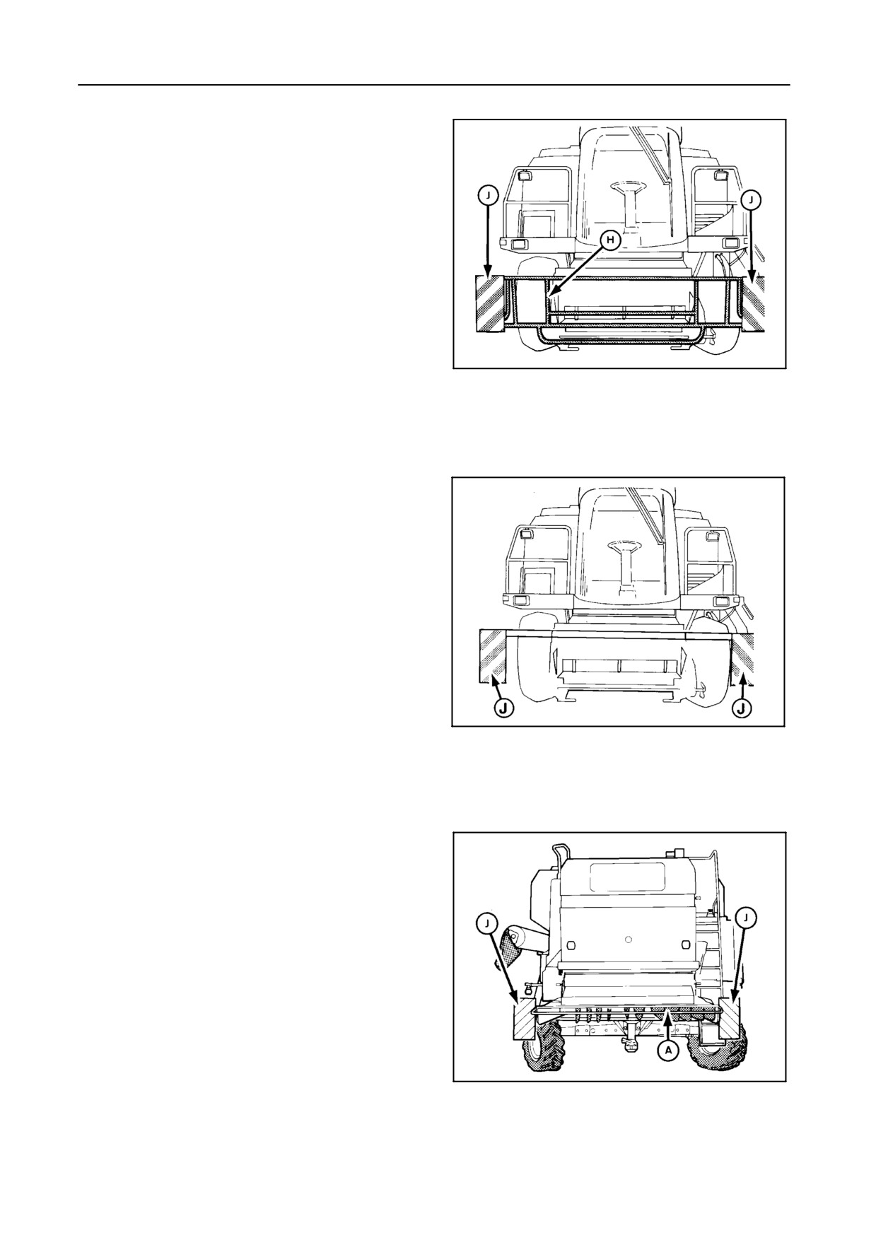
INTRODUCTION
Signal plates
For some countries, signal plates J must be installed
for road transport:
S Figure 18
At the front to the safety railing H, if installed.
42972
18
S Figure 19
To a profile fitted to the straw elevator.
51838
19
S Figure 20
At the rear to a frame fitted to the straw hood.
42965
20
1-22
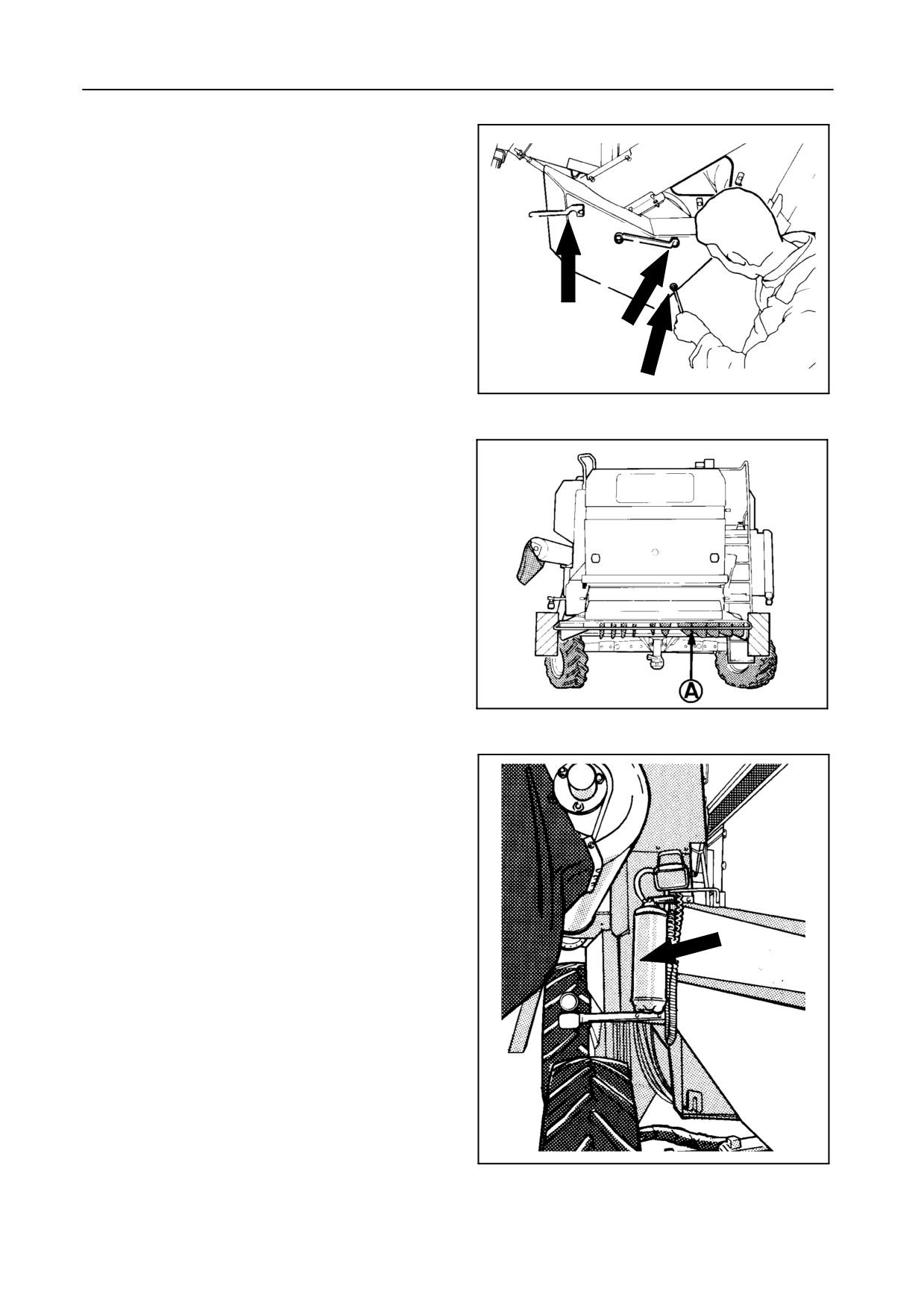
SECTION 1
Safety guards -- Figure 21
For safety’s sake and according to European
directives, safety guards now have locking devices
which can only be opened by means of the special
tool located on the left-hand side of the straw elevator,
a wrench (key width 13 mm) or a screw driver.
43037
21
Straw chopper spreader chute -- Figure 22
The straw chopper spreader chute A must remain in
the operating position (as shown) when driving on
public roads when the combine is not pulling a header
trailer.
42965
22
Fire extinguisher -- Figure 23
The fire extinguisher is located on the left-hand side
near the straw hood.
Check the operating instructions.
Once the extinguisher is discharged, no matter for
how long, it must be recharged.
30355
23
1-23
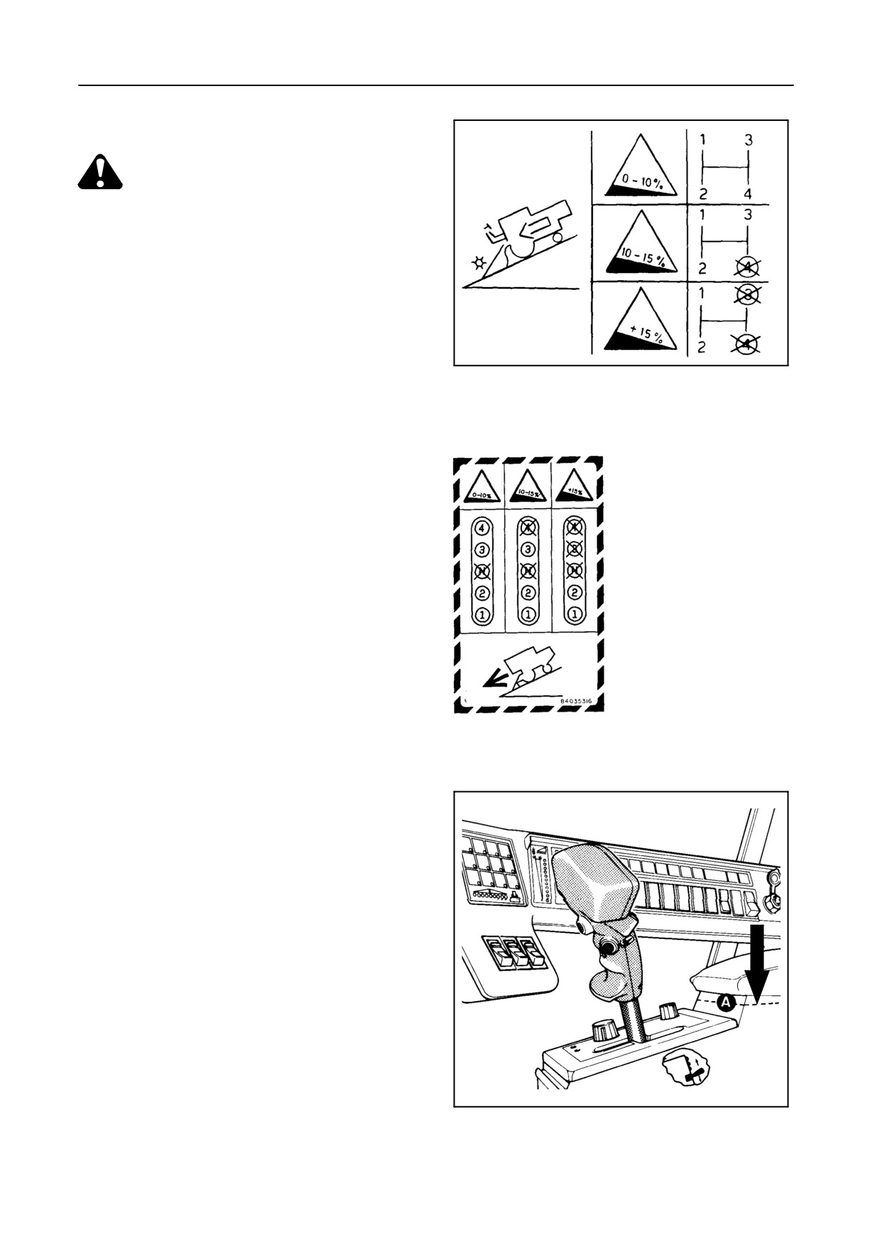
INTRODUCTION
DRIVING DOWNHILL -- Figures 24 to 26
WARNING:
To prevent runaway of the combine (i.e.
when the ground speed increases during
downhill driving and it is impossible to
reduce speed with the ground speed
control lever), it is necessary to shift into
a lower gear appropriate to the steepness
of the hill before starting the descent.
This information is given on a decal on
50672
plate A under the arm rest.
24
TX62-63-64PLUS-65PLUS-66-68-68PLUS
25
TX67
42759
26
1-24
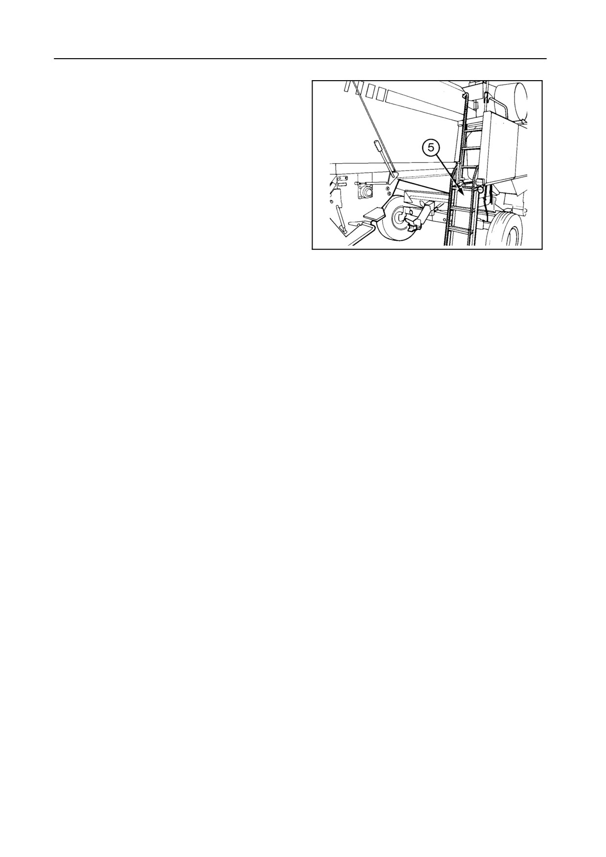
SECTION 1
Access protection to engine compartment --
Figure 27
Lowering the ladder 5 while the engine is running will
automatically cause the engine to be shut off. It is,
however, possible to start the engine while the ladder
is in the lowered position.
IMPORTANT:
Be aware that, if the engine is running with the
ladder in the lowered position, the engine
protection is not working.
43039
27
INTENDED USE
The TX60 Series combine harvesters are designed
purposes on cultivated land to harvest cereal crops,
as self-propelled units and are powered by an
small seed crops, maize, soy beans, etc., by cutting
on-board diesel engine.
or picking up from a swath, threshing and separating
the grain from the straw and temporarily storing it until
The machines are intended to be used for agricultural
it is unloaded into vehicles for transport.
1-25
INTRODUCTION
AIRBORNE NOISE EMISSION
In line with the European directive (EEC/86/188) and
It should be noted that the noise level may exceed 85
national legislation, listed below are the
dBa:
recommended noise levels at the operator’s ear,
measured in dBa, according to the ISO
5131
(a) if the machine is not equipped with a cabin, or
standard.
(b) if the machine is equipped with a cabin, but
The noise is measured with the engine and all
operating with doors and/or windows open.
mechanisms engaged and running at normal
operating speed for the specified use of the product
In these cases, the use of ear protection gear is
and without crop flow through the machine. For
recommended. In several countries this is mandatory,
machines with a cabin, the noise is measured with all
windows and doors closed and also in the open
so check local legislation.
position.
1-26
SECTION 1
ELECTROMAGNETIC COMPATIBILITY (EMC)
This product complies with the EEC directive 89/336
S Each element of non New Holland equipment
on Electromagnetic Interferences on electronic
ad-ded to this New Holland product must bear a
equipment if it is used in conjunction with equipment
CE mark.
which bears the CE mark.
S The maximum power of emission equipment
New Holland will take no liability for any problem
(radio, telephones, etc.) must not exceed the
arising as a result of its product working in an
limits imposed by the national authorities of the
environment of other equipment which does not
country of usage of the machine.
comply with the EEC directive.
Disturbances remain possible if added equipment
S The electromagnetic field generated by the added
does not meet the standards. As these interferences
system must not exceed 24 V/m at any moment
may result in serious malfunction of the machine
and at any location in the proximity of electronic
and/or create unsafe situations the following
components and the network between them over
instructions must be observed:
the entire machine.
SAFETY REQUIREMENTS FOR FLUID POWER SYSTEMS AND
COMPONENTS -- HYDRAULICS
(European standard pr EM 982)
Flexible hose assemblies must not be constructed
Before removing hydraulic accumulators for
from hoses which have been previously used as part
servicing, the liquid pressure in the accumulator must
of a hose assembly.
be reduced to zero.
Do not weld hydraulic piping.
Pressure check on hydraulic accumulators shall be
carried out by method recommended by the
When flexible hoses or piping are damaged, replace
accumulator manufacturer.
them immediately.
Care must be taken not to exceed the maximum
It is forbidden to modify a hydraulic accumulator by
allowable pressure of the accumulator. After any
machining, welding or any other means.
check of adjustment there must be no leakage of gas.
1-27
INTRODUCTION
VIBRATION LEVEL INFORMATION
The vibration level for the arms to which the operator
This information and measuring methods are in line
of this machine is exposed under normal operating
with the European Machinery Directive 89/392 EEC
conditions is below the 2.5 m/sec2 weighted root
paragraph 3.6.3.
mean square (RMS) value. The vibration level for the
whole body is below the 0.5 m/sec2 RMS value.
LEGAL OBLIGATIONS
Your machine may be equipped with special guarding
Therefore, check local legislation on the usage of this
or other devices in compliance with local legislation.
machine.
Some of these require active use by the operator.
1-28
SECTION 2
OPERATION
MACHINE FUNCTION
51597
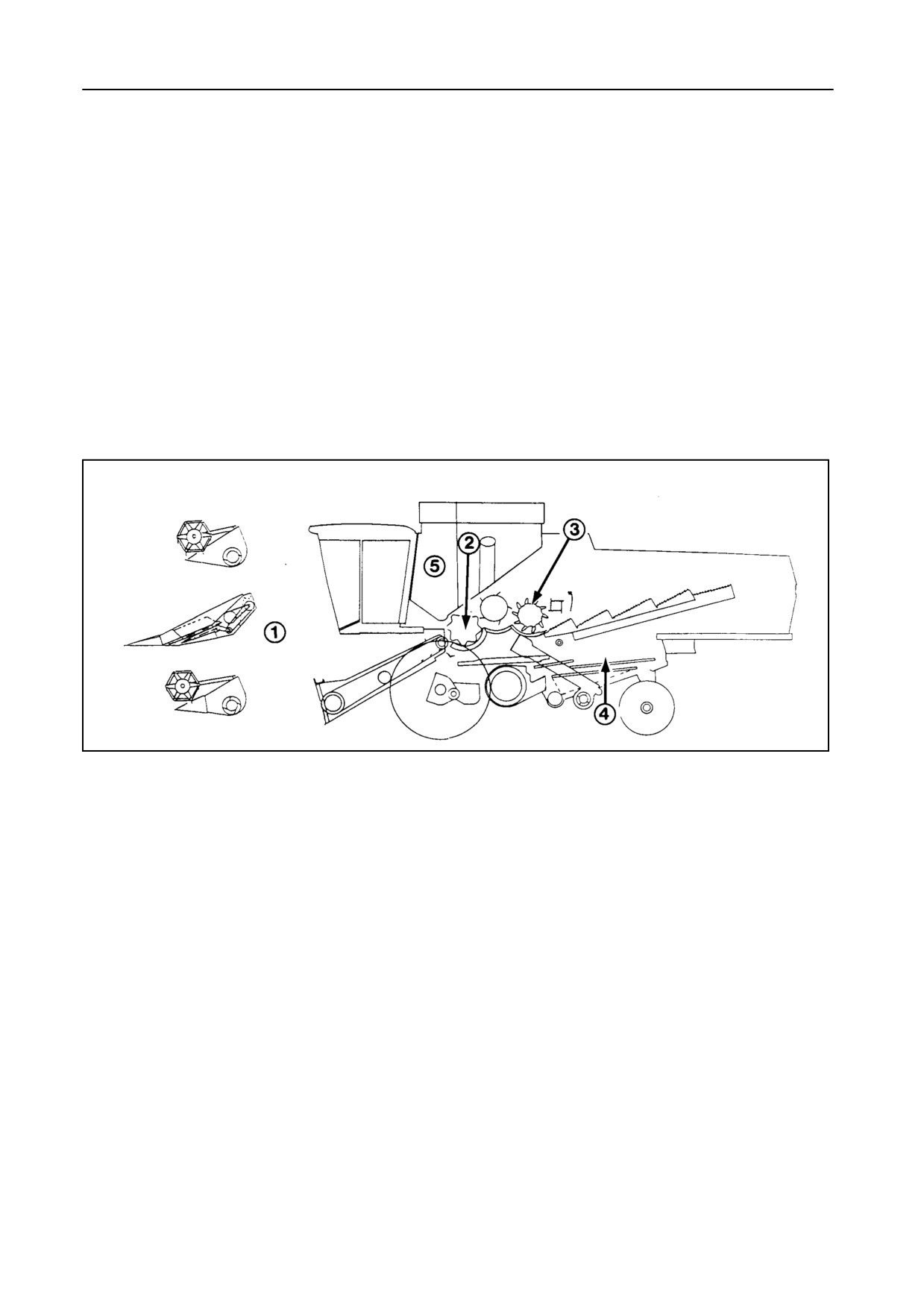
1
The combine harvester performs five basic func-
tions -- Figure 1:
1.
Feeding
2.
Threshing
3.
Separation
4.
Cleaning
5.
Grain storage and unloading
2-1
OPERATION
51512
2
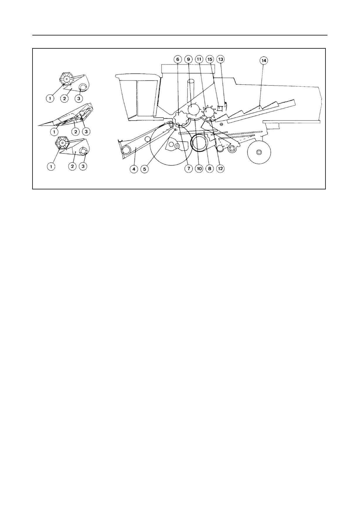
1. FEEDING -- Figure 2
The stone trap 5 is designed to trap stones and other
foreign objects which may cause damage to internal
parts of the combine.
The reel 1 (on the grain or flex header) or the gather-
ing chain (on the maize header) feeds the crop/cobs
into the header 2 towards the auger 3. The auger 3
feeds the crop into the front of the straw elevator 4.
2. THRESHING -- Figure 2
As the drum 6 rotates, it rubs the crop against the bars
of concave 7. This rubbing action threshes approxi-
Models with lateral flotation only:
mately 90% of the grain from the straw.
S Clean grain falls onto the grain pan 8.
The straw elevator head pivots on the elevator frame
S Straw (and a little grain) are guided to the beater 9.
which enables the header to follow deviations in slope
of up to 3° on either side, relative to the base unit posi-
S De-awning plates can be swung up underneath
tion.
the concave to increase the rubbing action when
threshing winter barley or difficult-to-thresh crops.
The crop is then carried up the straw elevator where it
S Rasp bars [accessory] can be installed on the
is fed over the stone trap 5 into the drum and concave
front part of the concave to improve the threshing
area. At this point the feeding is complete and the
efficiency (especially important in wheat) and to
threshing starts.
avoid white caps.
2-2
SECTION 2
3. SEPARATION -- Figure 2
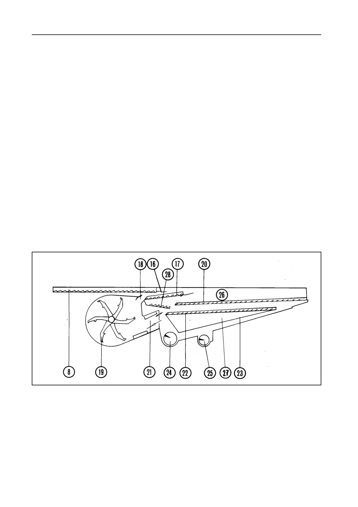
4. CLEANING -- Figures 3 and 4
Units with self-levelling cleaning shoe
The beater 9, with beater concave 10, strips the straw
from the drum and guides it to the rotary separator 11
The grain and chaff on the grain pan 8 are transported
and concave 12, which further separates the grain
to the rear by the reciprocating action of the exclusive
from the straw.
self-levelling cleaning shoe. An electrical actuator en-
sures that the cleaning shoe automatically remains
horizontal in the transverse axis of the machine, even
The straw retarding curtain 13 prevents the rotary
when operating on side slopes up to 17%. This inno-
separator from throwing the straw too far onto the
vation increases the capacity of the cleaning shoe
straw walkers 14.
considerably when operating in hilly conditions.
A Straw Flow beater 15 [if installed] improves the
Units with fixed cleaning shoe
straw transport towards the straw walkers and en-
ables a smoother flow of material in heavy crop condi-
As the cleaning shoe is not self-levelling, operation on
tions.
slight slopes is made possible by the installation of
hillside dividers on the grain pans and the upper sieve.
The straw walkers 14 oscillate, lift and tumble the
Hillside dividers are installed as standard equipment
straw, permitting the remaining grain to fall through
on the grain pan 8 where they ensure an even distri-
the walkers and slide down the walker return pans
bution of the material before it reaches the short grain
onto the rear of the grain pan 8.
pan 28.
51590
3
2-3
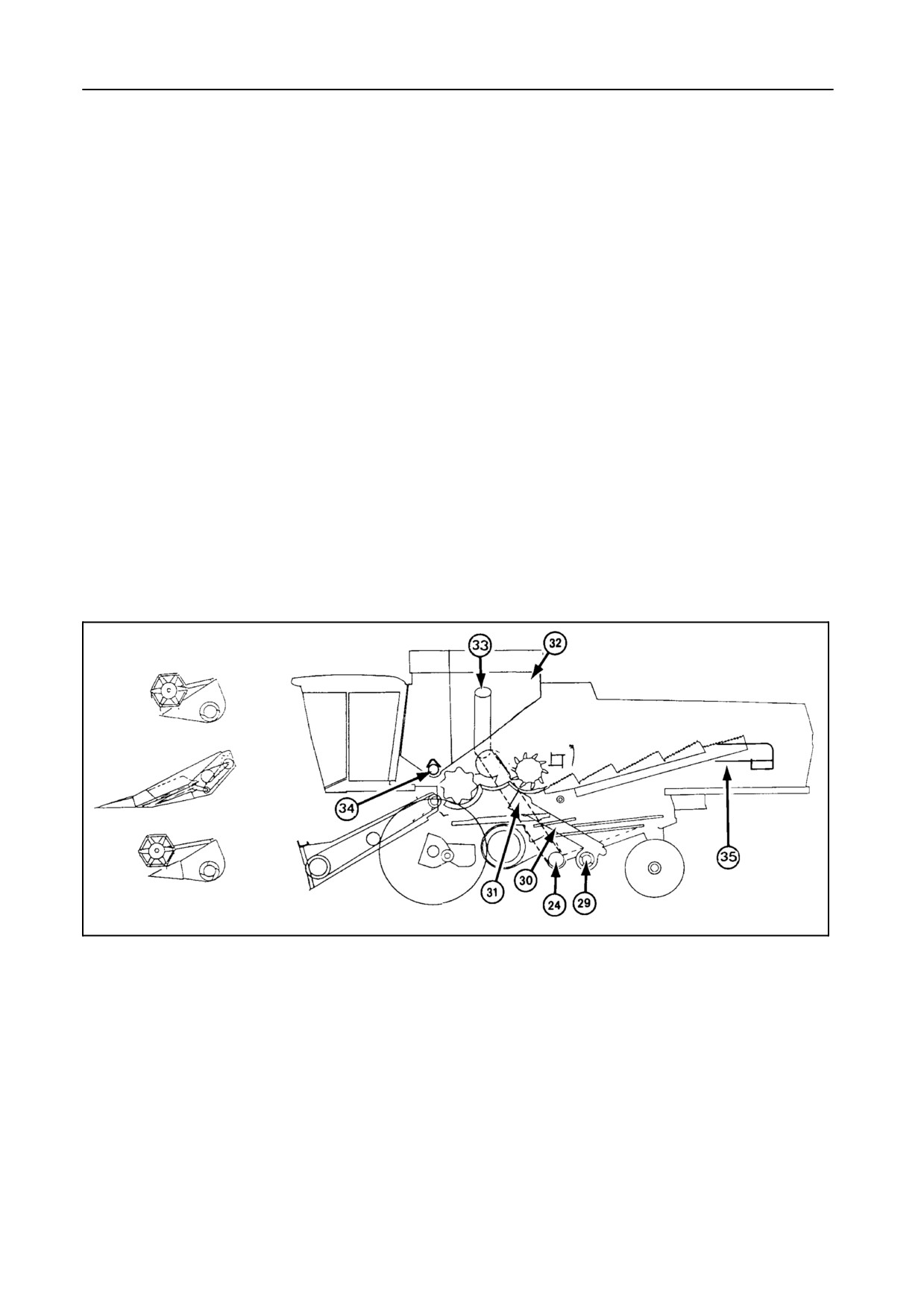
OPERATION
Hillside dividers can be installed as an accessory on
In addition, the grain separated by the presieve 17 is
the presieve 17 and upper sieve 20. They can be re-
guided by the small grain pan 28 to the lower sieve.
moved when operating in level field conditions.
The installation of a presieve considerably increases
the cleaning shoe capacity as the main separation of
The cleaning shoe is composed of an upper shoe 26
grain and chaff occurs at both finger grates. The lower
and a lower shoe 27 which move in opposite direc-
sieve, or cleaning sieve, provides the final cleaning
tions. A first separation takes place on the grain pan
operation. Grain that passes through the cleaning
as the lighter chaff forms the top layer and the heavier
sieve is carried over the grain plate 23 to the clean
grain the bottom layer. The material falls through the
grain cross auger 24. Unthreshed heads which do not
finger grate 16, installed at the rear of the grain pan,
fall through the lower sieve are split into two streams
onto the presieve 17. The air coming from the secon-
and are transported by the returns auger 25 to the
dary blow opening 18 of cleaning fan 19 blows the
roto-threshers 29 for rethreshing.
chaff over the presieve so that grain with a reasonably
high degree of cleanliness falls through the presieve.
From the roto-threshers this material is channelled by
This action will be repeated a second time between
returns augers 30 to the grain pan for cleaning. Di-
the presieve 17 and upper sieve 20.
vider plates divide the returned material evenly over
The air coming from the main blow opening 21 of
the grain pan where the exclusive self-levelling clean-
cleaning fan 19 blows the chaff over the upper sieve
ing shoe takes over.
and out of the machine, while the grain, unthreshed
heads and small volumes of chaff fall onto the lower
sieve 22.
51855
4
5. STORAGE -- Figure 4
The clean grain is channelled into the grain tank 32 by
the clean grain cross auger 24, grain elevator 31 and
bubble-up auger 33. The grain tank is emptied by the
grain tank unloading auger 34 and the unloading tube
auger 35.
2-4
SECTION
2
CONTROLS AND INSTRUMENTS
The following modules are described:
S Emergency exit
S Steering column and control pedals
S Arm rest module
S Instrument panel, comprising:
- InfoView monitor
- General module
- Control module
S Console module
S Cab roof instruments
S Operator’s seat
S Fuses and relays
S Other components
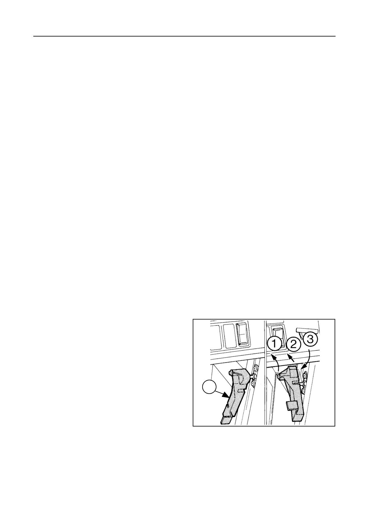
EMERGENCY EXIT -- Figure 5
The right-hand door is the emergency exit.
To escape from the cab through the emergency exit,
proceed as follows :
1. Unlock the emergency exit door handle A in 3
A
steps, as shown, and open the door completely.
2. Pivot the InfoView monitor away from the emer-
gency exit.
42970
5
3. Step over the dashboard and leave the cab.
4. Use the railing and light beam as handholds,
and the traction tyre and additional step along the
straw elevator to step on.
2-5
OPERATION
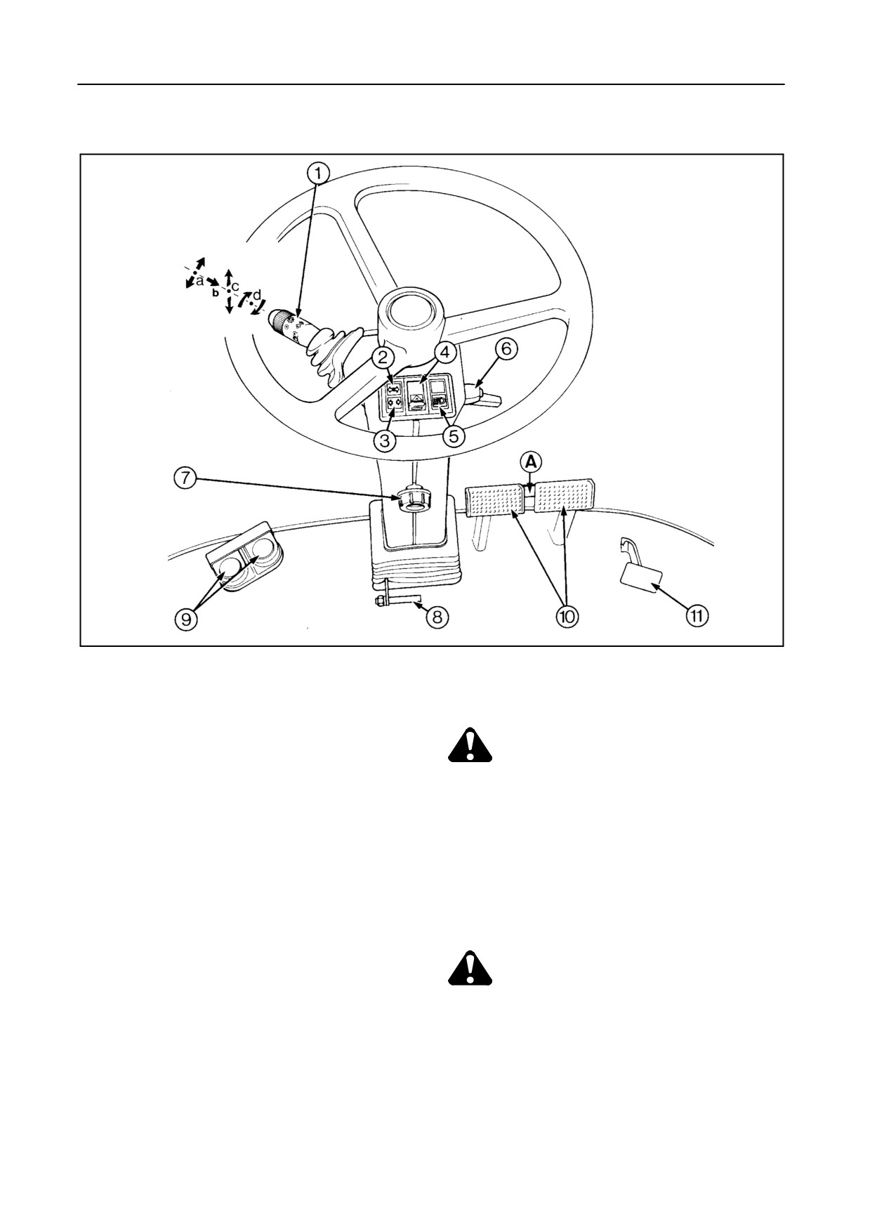
STEERING COLUMN AND CONTROL PEDALS -- Figure 6
42764
6
1
-a
Direction indicator lever
(linked up with
8
Steering column tilt control (push pedal)
buzzer)
-b
Push button for horn
CAUTION:
-c
Headlights selector switch
Adjust the steering wheel only when the
combine is stopped.
-d
Parking and dipped headlights switch and all
outside 12-Volt DC plugs (portable light)
9
Reel fore and aft adjustment
-
Right-hand pedal: forwards
2
Direction indicator warning light
-
Left-hand pedal: rearwards
3
Header trailer direction indicator warning light
10
Foot brake pedals with pedal coupler A
(linked up with buzzer)
4
Hazard warning lights switch (linked up with
buzzer)
CAUTION:
For safety reasons, always couple brake
5
Headlights control indication
pedals by means of pedal coupler A when
6
Steering wheel tilt control (clamping screw)
driving on public roads. This ensures the
brakes are actuated together.
7
Steering wheel height control (clamping
screw)
11
Differential lock pedal [if installed]
2-6
//////////////////////////////////////////