New Holland Tractor Workmaster 50 / Workmaster 60 / Workmaster 70 / Tier 4B (final). SERVICE MANUAL - page 29
6 - WORKING OPERATIONS
Front ballast weights (optional)
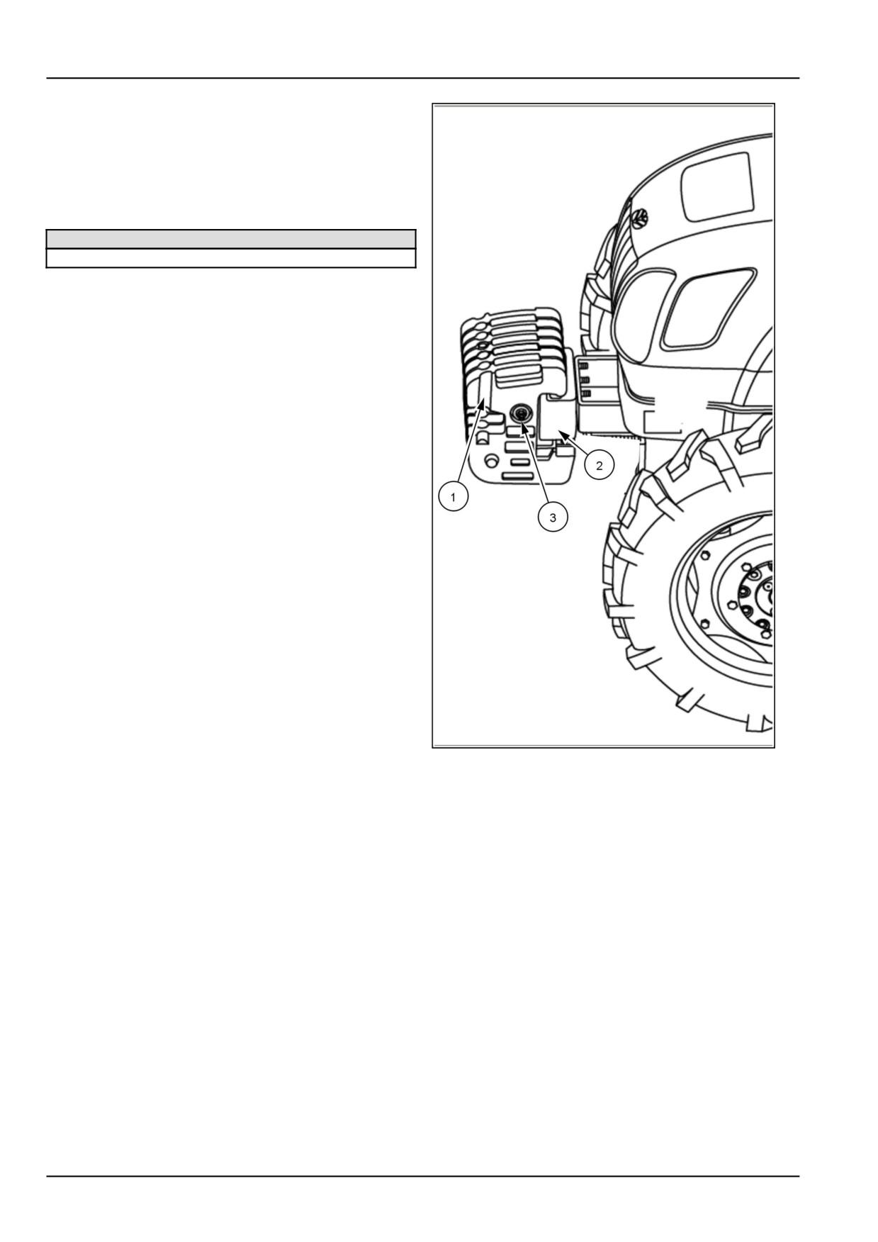
The front ballast weights (1) are available from your au-
thorized dealer, which can be mounted on a front carrier
(2). Wafer weights can be mounted and clamped together
by means of the long through bolt (3). The maximum rec-
ommended front ballast weight is:
Front ballast weights
6 X 30.0 kg (66.1 lb) = 180.0 kg (396.8 lb)
GNIL14TR00535AA
2
6-22
6 - WORKING OPERATIONS
Liquid ballast (Optional)
It is a common practice to add weight to the tractor by fill-
ing the rear tires with liquid. A calcium chloride (CaCl2)
and water solution is recommended due to the low freez-
ing point and greater density (weight per gallon) than pure
water.
Never exceed the total recommended weight for the trac-
tor. Because special equipment is required to fill the tires,
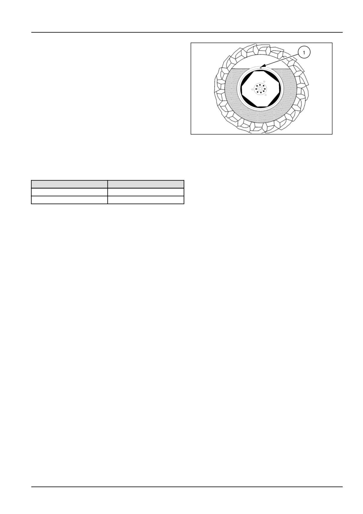
consult your dealer. Tires should never be filled beyond
75 %. At 75 % full, the liquid will come to the valve stem
(1) when the valve stem is at the highest point, at the top
of the wheel.
20108794
3
Rear tire liquid
Ballast Weights (Per Tire)
600 grams/liter
(5 lbs/gal) CaCl2 %
Solution
Tire Size
Weight per tire
13.6-28
211 kg (465 lb)
14.9-28
261 kg (575 lb)
6-23
6 - WORKING OPERATIONS
Tire inflation
DANGER
Explosion hazard!
Welding to a wheel can create an explosive air
and gas mixture. Removing air from the tire or
loosening the tire on the wheel (breaking the
bead) will NOT eliminate the hazard. ALWAYS
remove the tire completely from the wheel be-
fore welding.
Failure to comply will result in death or serious
injury.
D0033A
WARNING
Explosion hazard!
When inflating tires, use a clip-on air chuck
with a gauge, remote valve, and hose long
enough to allow you to stand to one side and
NOT in front of or over the wheel assembly.
Keep others out of the DANGER AREA. Never
inflate a tire beyond the maximum allowable
pressure printed on the tire.
Failure to comply could result in death or se-
rious injury.
W0059A
WARNING
Explosion hazard!
Do not remove, install, or make repairs to a tire
on a wheel rim. Take the tire and rim to a tire
shop where persons with special training and
special safety tools are available.
Failure to comply could result in death or se-
rious injury.
W0365A
Upon receiving your tractor, check the air pressure in the
tires and recheck every 50 hours or weekly. Refer below
table for tire pressure for normal operation.
Operation
Front
Rear
Field
220 kPa (32 psi)
69 - 110 kPa (10 -
16 psi)
Haulage
220 kPa (32 psi)
110 - 179 kPa (16 -
26 psi)
Industrial
310.3 kPa (45.0 psi)
165.0 kPa (23.9 psi)
See the tables for tire pressure and permissible load for
more details.
When checking tire pressures, inspect the tires for dam-
aged tread and side walls. Incorrect pressure will lead to
premature tire failure.
Do not exceed the load for the pressures listed. Do not
over-inflate or under-inflate the tire.
6-24
6 - WORKING OPERATIONS
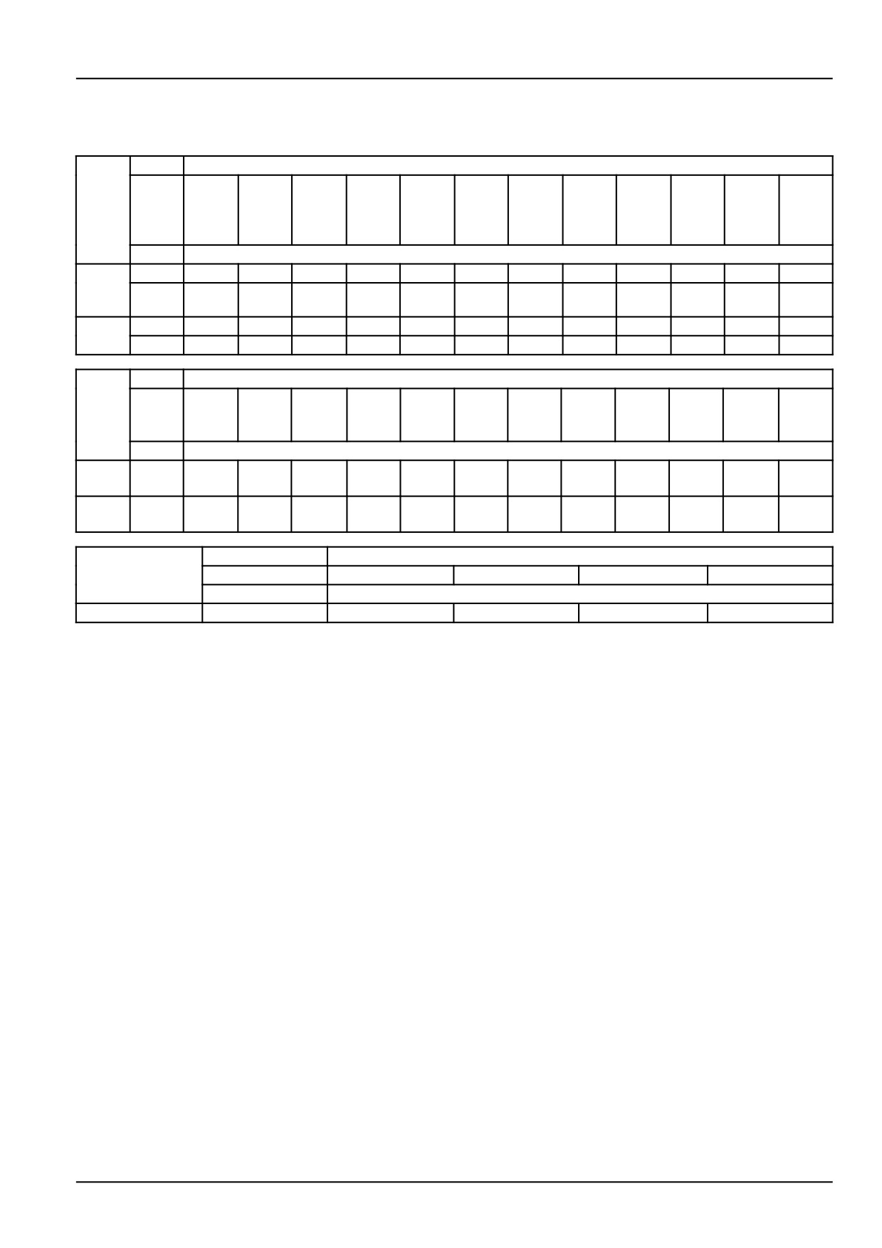
Front tire pressure and permissible loads
The following chart gives the load carrying capacity of the tires at the tire pressure indicated:
Tire
Cold Inflation Pressure - kPa (psi)
Size
141
169
200
228
248
279
310
341
372
400
421
448
kPa
kPa
kPa (2
kPa (3
kPa (2
kPa
kPa (4
kPa
kPa (5
kPa (5
kPa (6
kPa (6
(20.5
(24.5
9 psi)
3 psi)
6 psi)
(40.5
5 psi)
(49.5
4 psi)
8 psi)
1 psi)
5 psi)
psi)
psi)
psi)
psi)
Maximum load per tire - kg
7.50
6 ply
500
535
605
660
695
745
-
-
-
-
-
-16
8 ply
500
535
605
660
695
745
790
830
870
(2WD)
9.5-24
6 ply
740
770
795
825
855
880
915
940
—
—
—
-
(4WD)
8 ply
740
770
795
825
855
880
915
940
965
990
1015
1040
Tire
Cold Inflation Pressure - kPa (psi)
Size
83 kPa
96.5
110
124
138
152
165
179
193
207
(12 p-
kPa (1
kPa (1
kPa (1
kPa (2
kPa (2
kPa (2
kPa (2
kPa (2
kPa (3
si)
4 psi)
6 psi)
8 psi)
0 psi)
2 psi)
4 psi)
6 psi)
8 psi)
0 psi)
Maximum load per tire - kg
8.3-24
6 ply
400
438
463
500
531
558
-
-
-
-
-
-
(FWD)
9.5-24
6 ply
500
544
580
630
671
712
748
776
826
848
-
-
(FWD)
Tire Size
Cold Inflation Pressure - psi
28 psi
36 psi
45 psi
61 psi
Maximum load per tire - lb
12.5-18(FWD)
10 ply
4435 lb
5240 lb
6005 lb
7205 lb
The above charts are for tractors operated at speeds up to 32 km/h (20 mph). Under front-end loader applications at
speeds up to 8 km/h (5 mph), the above loads may be increased by 50% maximum for the same inflation pressure.
6-25
6 - WORKING OPERATIONS
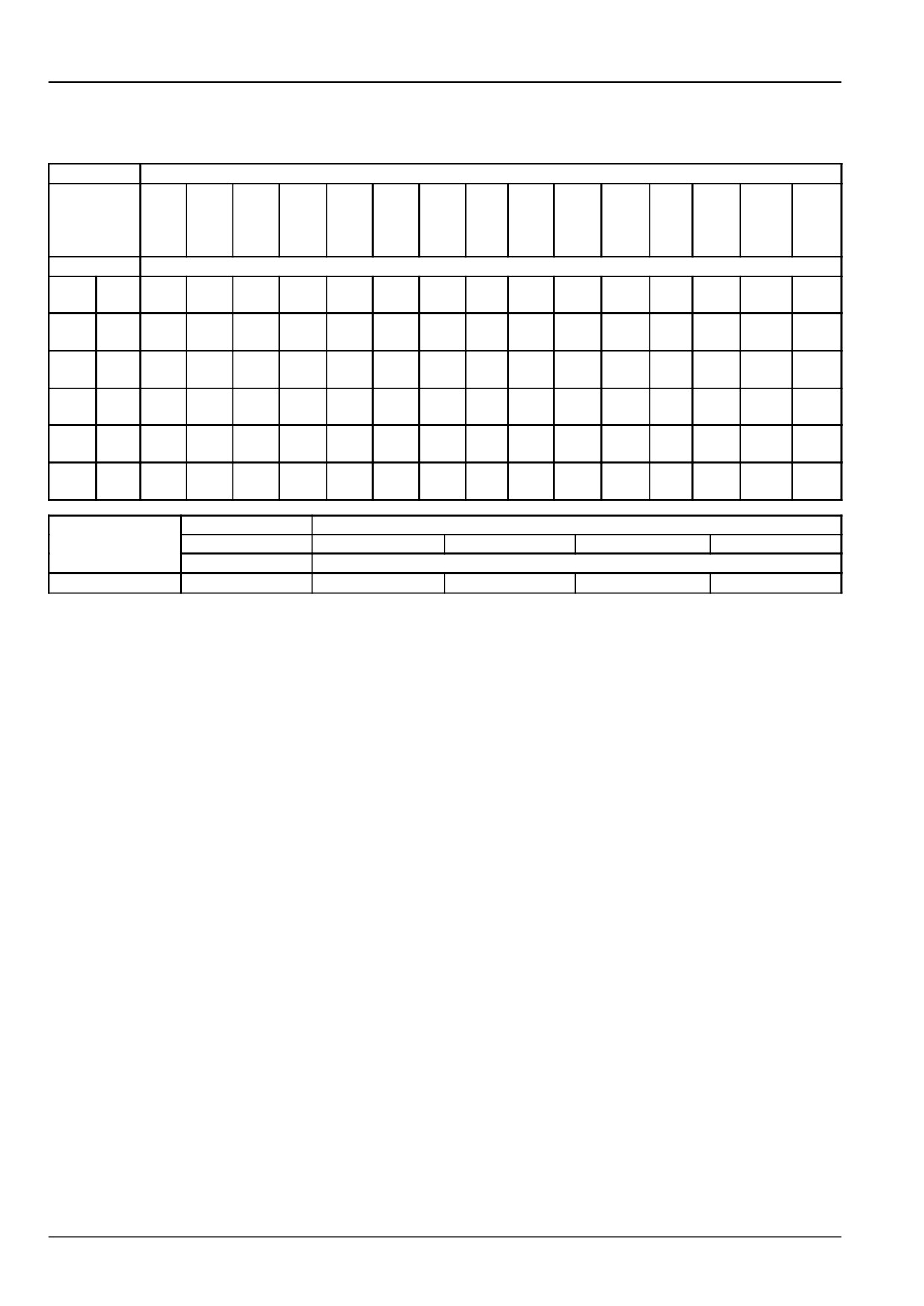
Rear tire pressure and permissible loads(cross ply tires)
The following chart gives the load carrying capacity of the rear tire at the pressure indicated.
Tire size
Cold Inflation Pressure - kPa (psi)
90
100
110
121
131
141
152
159
169
179
190
200
210
221
228
kPa
kPa (
kPa
kPa
kPa
kPa (
kPa
kPa
kPa (
kPa
kPa
kPa
kPa
kPa (3
kPa
(13
14.5
(16
(17.5
(19
20.5
(22
(23
24.5
(26
(27.5
(29
(30.5
2 psi)
(33 p-
psi)
psi)
psi)
psi)
psi)
psi)
psi)
psi)
psi)
psi)
psi)
psi)
psi)
si)
Maximum load per tire - kgs
13.6
8 ply
1060
1120
1180
1230
1285
1340
1395
1450
1500
1550
1370
1650
-
-
-
-28
1660
10
1060
1120
1180
1230
1285
1340
1395
1450
1500
1550
1660
1650
1700
1750
-
ply
12
1060
1120
1180
1230
1285
1340
1395
1450
1500
1550
1660
1650
1700
1750
1180
ply
14.9
8 ply
-
-
1410
1475
1545
1610
1675
1740
1810
1880
-
-
-
-
-28
10
-
-
1410
1475
1545
1610
1675
1740
1810
1880
1930
1975
2020
-
-
ply
12
-
-
1410
1475
1545
1610
1675
1740
1810
1880
1930
1975
2020
2070
2120
ply
Tire Size
Cold Inflation Pressure - kPa
120 kPa
140 kPa
150 kPa
165 kPa
Maximum load per tire - kg
18.4-24
8 ply
2390 kg
2600 kg
2760 kg
3020 kg
To avoid the possibility of tire creep (movement of the tire on the rim), tire pressure below 90 kPa (13 psi) should
not be used with cross ply tires for operations having a high torque requirement, e.g., sub-soiling, heavy transport,
etc. When mounted implements are used on tractor, loads may be increased by 20 % with no increase in inflation
pressure, if operated at speeds up to 6 km/h (4 mph).
For haulage service, it is recommended that the tire be inflated to the maximum pressure stipulated in the table.
The above chart is for guidance only. For exact information regarding inflation pressures and loads for your particular
tires, consult your dealer.
6-26
7 - MAINTENANCE
7 - MAINTENANCE###_7_###
GENERAL INFORMATION
Lubrication and maintenance general information
Introduction
• Air filter: check clogging indicator (clean if required)
• Check engine oil
This section gives full details of the service procedures
necessary to maintain your tractor at peak efficiency. The
During first 50 hour operation
lubrication and maintenance chart provides a ready ref-
erence to these requirements ,see 7-11. Each operation
In addition to the regular maintenance operations listed,
being numbered for easy reference. If in doubt about any
check the following items every 10 hours or daily during
aspect of lubrication and maintenance, consult your au-
the first 50 hours of operation:
thorized dealer.
• Check engine oil.
Safety precautions
• Check Transmission/Hydraulic, rear axle oil level.
Read and observe all safety precautions listed in "Servic-
• Wheel nuts for tightness.
ing the Tractor" in the safety rules section at the front of
NOTICE: Park the tractor on level ground and where ap-
this Manual. See 2-2.
plicable, extend all cylinders on implements or attach-
NOTE: Dispose of used filters and fluids properly.
ments before checking these oil levels.
CAUTION
The first 50 hour service
Maintenance hazard!
Always stop the machine before perform-
At the first 50-hours service, ensure that the following
ing any lubrication. Observe the following
additional service operations are carried out. The items
precautions before leaving the operator's
are listed in the "First 50-Hour service" check list
platform: Disengage all drives. Engage the
• Change hydraulic oil filter.
parking brake. Raise the header. Engage the
header lifter safety latch. Turn the machine
• Check and tighten all cooling system hose connections.
engine OFF. Remove the ignition key.
• Check and tighten all air intake connections.
Failure to comply could result in minor or
moderate injury.
• Check and torque front end weight bolts.
C0029A
• Check torque of all wheel nuts
10 hours or daily check
• Coolant: check coolant level (top up if required)
7-1
7 - MAINTENANCE
NOTICE: Items listed in first 50-hours service are impor-
adverse (Wet, muddy, sandy, or extremely dusty) working
tant. If not performed, early component failure and re-
conditions.
duced tractor life may result.
Lubrication and maintenance chart
Preventing system contamination
The chart lists the intervals when the routine checks, lubri-
To prevent contamination when changing oils, filters, etc.,
cation, service and/or adjustments should be performed.
always clean the area around the filler caps, level and
Use the chart as a quick reference guide when servicing
drain plugs, dipsticks, and filters prior to removal. To pre-
the tractor, see 7-11.
vent dirt entry during greasing, wipe dirt from the grease
fittings before greasing. Wipe excess grease from the fit-
Warranty notice
ting after greasing.
NOTICE: While any company can perform necessary
maintenance or repairs on your equipment, NEW HOL-
Flexibility of maintenance intervals
LAND strongly recommends that you use only authorized
NEW HOLLAND dealers and products that meet the
The intervals listed in the lubrication and maintenance
given specifications. Improperly or incorrectly performed
chart are guidelines to be used when operating in normal
maintenance and repair voids the equipment warranty
working conditions.
and may affect service intervals.
Adjust the service intervals for environment and extreme
working conditions. Intervals should be reduced under
7-2
7 - MAINTENANCE
Refueling the tractor
• Avoid using fuel mixed with water or other substances
which may damage the engine.
WARNING
Fire hazard!
• Use fuel with a low sulfur content. The percentage of
sulfur must never exceed 10 - 50 ppm.
When handling diesel fuel, observe the follow-
ing precautions:
If the percentage of sulfur contained in the fuel exceeds
the value indicated, the particulate filter will not work
1. Do not smoke.
2. Never fill the tank when the engine is run-
properly.
ning.
All fuels are inflammable. Any fuel leaking or dropping
3. Wipe up spilled fuel immediately.
on hot surfaces and electric components can cause
Failure to comply could result in death or se-
fires. Do not smoke when refueling or nearby any filling
rious injury.
station.
W0099A
Fuel requirements (recommended fuel)
• During refueling, make sure the fuel does not contain
any residue; in this case use specific filters.
7-3
7 - MAINTENANCE
Refueling the Tractor
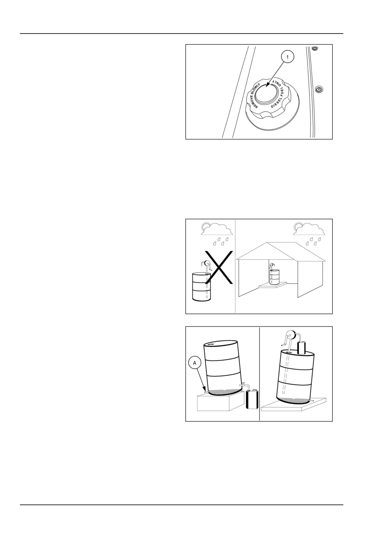
The fuel tank filler cap (1) is located at the rear of the front
hood. Before removing the cap, wipe all dust and dirt from
around the cap to prevent debris from falling into the tank
while filling.
Use an approved fuel container and check the inside of
the container periodically for cleanliness. Fuel tank ca-
pacity is 51 l (13.5 US gal)
NOTICE: The fuel cap is a vented-type. Use only an ap-
proved NEW HOLLAND replacement cap to prevent fuel
system-related problems.
If there is no filter on the storage tank or fuel container,
20108795
1
filter the fuel through a 100-mesh or finer screen when fill-
ing the tractor fuel tank. Keep the tractor tank as full as
possible (without filling to capacity) to minimize conden-
sation.
NOTICE: It is a good practice to fill the fuel tank at the end
of each day, as this will reduce overnight condensation.
Fuel storage
Take the following precautions to ensure that the stored
fuel is kept free of dirt, water and other contaminants.
1. Store the fuel in black iron tanks, not galvanized tanks,
as the zinc coating will react with the fuel and form
compounds that will contaminate the injection pump
and injectors.
2. Install bulk storage tanks away from direct sunlight.
20108796
2
3. Keep the tank slightly tilted so that the sediments will
settle away from the outlet pipe. To facilitate moisture
and sediment removal provide a drain plug at the low-
est point at the end opposite the outlet pipe.
4. If fuel is not filtered from the storage tank, put a funnel
with a fine mesh screen in the fuel tank filler neck when
refuelling.
5. Arrange fuel purchase so summer grade fuels are not
held over & used in winter.
20108797
3
(A) Drain Plug
Fuel saving tips for optimum performance
Proper maintenance of Tractor reduces fuel consumption
1. Store fuel in properly cleaned, rust and contamina-
to a greater extent.
tion free containers.
7-4
7 - MAINTENANCE
2.
Always fill the tank at the end of each day to reduce
9.
Do not run the engine in idle condition for more than
overnight condensation of moisture in the air, in turn
two minutes. It may result in wastage of fuel.
to avoid damage to the fuel system.
10.
Do not rest your foot on clutch pedal, as this will
3.
Fuel filters should be replaced as per recommended
cause clutch slippage, loss of engine power and in-
time schedule as the filtering capacity is not retained
creased fuel consumption. Maintain the specified
after this specified time. It may allow harmful contam-
clutch pedal free play.
ination and damage the fuel injection system. Follow
11.
Always drive the tractor in proper gear.
the service schedule for draining the water from the
filters and cleaning the feed pump filter.
12.
Use a lower gear while driving down a slope and use
brakes sparingly.
4.
Always use genuine fuel filters available from your
Authorized Dealers.
13.
Maintain proper tire pressures for field work as well
as for roadwork. Refer the tire pressure chart given
5.
Stop diesel leakage, if any, immediately.
in this manual. Worn out tires causes wheel slippage
6.
Dirt particles entering the engine causes early wear
and waste fuel. Re-tread or replace the tires if they
of liners and piston rings, resulting in loss of power,
are badly worn out. Adhere to tire ballasting as and
engine oil & fuel consumption. Clean the pre-cleaner
when required to reduce wheel slippage and fuel con-
bowl daily and change the air cleaner oil as men-
sumption.
tioned in service schedule. Ensure that there is no
14.
Always use matching implements to cut down the
leakage through hoses and the air cleaner bowl seal
diesel wastage. Implements should be maintained
is in good condition, keep hose clamps tight.
in good condition, as usage of worn out implements
7.
Check the Radiator coolant level daily and top-up
will waste fuel.
with clean water only. Radiator fins should always
15.
Always plow length wise and plan your field run to
be kept clean. Should it be necessary to replace
reduce fuel consumption. Adjust the wheel track to
radiator cap, use only genuine cap of the specified
suit the implement and avoid overlap when working
pressure. Never try to remove the thermostat. Check
in the field.
and adjust fan belt tension regularly. Ignoring these,
will result in engine over heating and heavy diesel
16.
When using a PTO driven equipment, operate the
consumption.
engine at the recommended speed to reduce fuel
consumption.
8.
Follow the running-in procedure given in this manual
for optimum performance of your tractor.
7-5
7 - MAINTENANCE
Biodiesel fuel
Fatty Acid Methyl Ester Biodiesel (Biodiesel Fuel) con-
With Biodiesel Fuels, it may be necessary to change the
sists of a family of fuels derived from vegetable oils
engine oil, engine oil filter and fuel filter elements more
treated with methyl esters.
frequently than with Diesel Fuels. Biodiesel Fuel can re-
move rust and particles from the inside of on-site fuel stor-
The use of biodiesel blends meeting Specification Stan-
age tanks that would normally adhere to the sides of the
dards ASTM 6751 or EN14214 are approved for your en-
tank. Like particles deposits that commonly occur with
gine up to B5 ( 5 % blend ratio). It is highly recommended
Diesel Fuel, these particles can become trapped by the
to use biodiesel fuel from accredited suppliers to maintain
machine fuel filters, causing blockage and shortening fil-
quality and consistency of the fuel.
ter life. In cold weather, this is more likely to happen.
Consult you dealer for information on cold weather oper-
NOTICE: It is imperative that you check which blend is ap-
ation and proper maintenance intervals when using any
proved for your engine with your local dealer. Beware that
Biodiesel Fuel blend.
the use of Biodiesel Fuel that does not comply with the
Standards mentioned above could lead to severe dam-
When handling Biodiesel Fuel, care must be taken not to
age to the engine and fuel system of your machine. The
allow water into the fuel supply. Biodiesel Fuel will ac-
use of fuels that are not approved may void Warranty cov-
tually attract moisture from the atmosphere. Fuel tanks
erage.
must be kept as full as possible to limit the amount of air
and water vapors in them. It may be necessary to drain
Biodiesel Fuel Usage Conditions
the fuel filter water tap more frequently.
NOTICE: The Biodiesel Fuel must meet the fuel Specifi-
cation mentioned above.
Potential oxidation and stability could be a problem with
the fuel stored in the machine.
Biodiesel Fuel must be purchased from a trusted sup-
NOTICE: Machines must not be stored for more than 3
plier that understands the product and maintains good
months with Biodiesel Fuel blends in the fuel system.
fuel quality. Biodiesel Fuel must be pre-blended by the
supplier. Mixing Biodiesel Fuels on-site can result incor-
If long storage periods are necessary, the engine must
rect mixture that can lead to problems with both engine
run on Diesel Fuel for 20 hours to flush the Biodiesel Fuel
and fuel system.
out of the engine fuel system prior to storage.
Engine performance is affected by the use of Biodiesel
NOTICE: Biodiesel Fuel must not be stored in on-site stor-
Fuel. There may be up to 12 percent reduction in power
age tanks for more than 3 months.
or torque depending on the blend used.
Any spillage of Biodiesel Fuel must be cleaned up imme-
NOTICE: DO NOT modify the engine and/or injection
diately before it can cause damage to the environment
pump settings to recover the reduced performance.
and the paint finish of the machine.
The reduced power must be accepted if using any
Before using Biodiesel Fuel blends you should consult
Biodiesel Fuel blend.
with your dealer to receive full information about the ap-
proved blend for your machine and any detailed condi-
Some modification may be required to allow your engine
tions of its usage.
to run Biodiesel Fuel. Consult you dealer for complete
information on these modifications.
NOTICE: Be aware that not fulfilling the requirements and
conditions of Biodiesel Fuel usage may void your ma-
Biodiesel Fuel has a higher cloud point than Diesel Fuel.
chine's Warranty coverage.
NOTICE: The uses of high Biodiesel Fuel blends are not
recommended in cold weather conditions.
7-6
7 - MAINTENANCE
Machine shields and guards - Basic instructions
Guards
To gain access to perform inspection, lubrication and
maintenance operations, the hood and certain access
panels may need to be opened and removed.
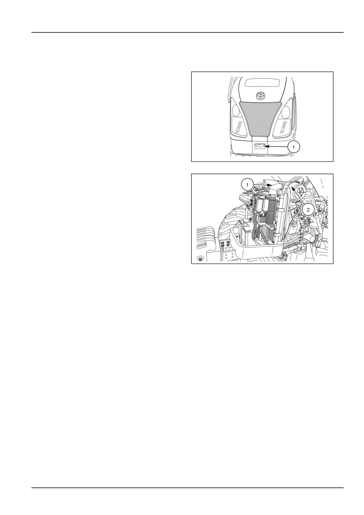
Engine hood
The hood is hinged at the rear to allow easy and safe
access to the various engine components. In order to
open the hood, slide the lock to, right, and with the help
of the handle (1), raise the hood.
GNIL14TR00533AA
1
To maintain the hood in the raised position a gas strut is
provided on the underside of the hood ensuring access to
the radiator cap, (1), and air cleaner (2).
GNIL14TR00529AA
2
7-7
7 - MAINTENANCE
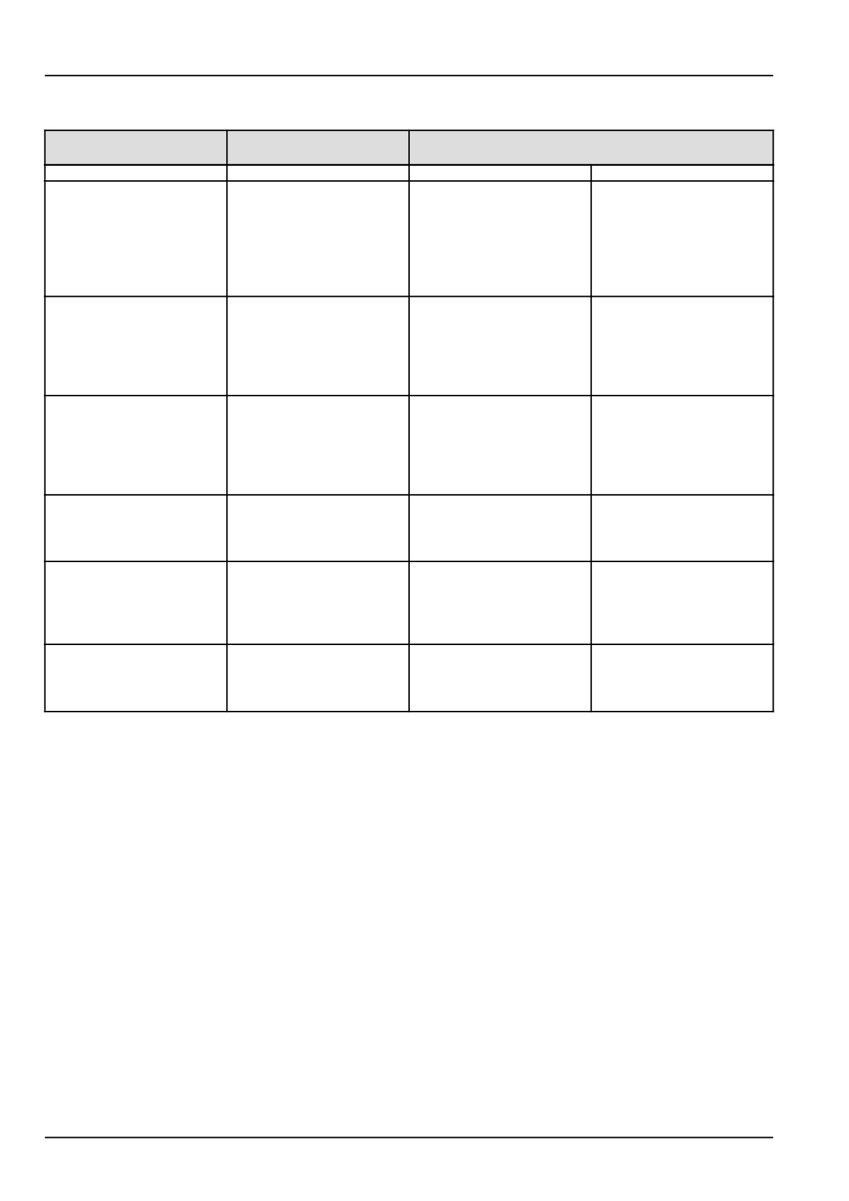
Consumables
Recommended fluids and
International specification
Approximate quantities
application
Engine oil
API CJ4
6.3 l (6.6 US qt)
6.3 l (6.6 US qt)
NEW HOLLAND AMBRA
AUTO SUPREME 5W-30
NEW HOLLAND AMBRA
UNITEK MASTERGOLD
SBL CJ-4 SAE 10W-40.
See 7-20.
Transmission oil or rear
axle oil
API GL4, ISO 32/46
23.0 L (24.3 US qt) for
2WD
25.0 L (26.4 US qt) for
4WD
NEW HOLLAND
AMBRA MULTI G
134™ HYDRAULIC
TRANSMISSION OIL
Front axle differential or
final reduction gear case
API GL4, ISO 32/46
7.5 l (8.0 US qt)
7.5 l (8.0 US qt)
NEW HOLLAND
AMBRA MULTI G
134™ HYDRAULIC
TRANSMISSION OIL
Grease fittings or bearings
NEW HOLLAND AMBRA
NLGI No. 2
As required
As required
GR-9 MULTI-PURPOSE
GREASE.
Steering oil (Hydraulic)
NEW HOLLAND
API GL4, ISO 32/46
2.0 l (2.1 US qt)
2.0 l (2.1 US qt)
AMBRA MULTI G
134™ HYDRAULIC
TRANSMISSION OIL
Engine radiator coolant
System Capacity
8.5 l (9.0 US qt)
8.5 l (9.0 US qt)
*Water
50%
50%
Ethylene Glycol
50%
50%
7-8
7 - MAINTENANCE
Protecting the electrical system during charging or welding
3. Do not run the alternator without battery in the circuit.
DANGER
4. Do not use high voltage bulbs as warning light.
Hazardous chemicals!
Battery electrolyte contains sulfuric acid.
Maintenance of the Battery
Contact with skin and eyes could result in
severe irritation and burns. Always wear
1.
Batteries should not be allowed to discharge com-
splash-proof goggles and protective clothing
pletely. If the tractor is to be stored for a period of
(gloves and aprons). Wash hands after han-
more than 2 weeks, the battery should be removed
dling.
from the tractor and stored in dry location in a wooden
Failure to comply will result in death or seri-
platform. Trickle charge every 2 to 3weeks to maintain
ous injury.
the battery in good condition.
D0105A
2.
Ensure that the electrolyte level in all battery cells is
preferably at the maximum level. However, in general,
Precautions
the level should be between minimum and maximum
marks. Add distilled water, if the electrolyte level is
To avoid damage to the electrical systems, always
found below the minimum level. Do not use well/tap
observe the following:
water. Do not top off with acid.
1. Never make a break in any of the charging circuit con-
3.
The specific gravity in every cell of the battery should
nections, when the engine is running.
ideally be between 1.260 - 1.230. At any point of time,
2. Never short any of the charging components to earth.
specific gravity in cells should not fall below 1.230. If
the reading is below 1.230, then the battery shows
3. Do not use a slave battery of higher than 12 V nominal
symptoms of a discharged battery. Please refer it to
voltage.
your Battery Dealer.
4. Always disconnect the ground cable from the batteries
4.
Always apply the battery terminals with petroleum
before carrying out arc welding on the tractor or on any
jelly to avoid current leakage and rusting. Never use
implement attached to the tractor.
grease for the same purpose.
5. Position the welder ground cable clamp as close to the
5.
Always disconnect the ground terminals (negative ter-
welding area as possible.
minal) of the battery, while carrying out any repairs on
6. Never allow welding cables to lay on, near or across
the tractor, especially during welding.
any electrical wiring or electronic component while
6.
Do not crank the engine for more than ten seconds at
work is in progress.
one time. Wait for about thirty seconds and then crank
7. Always disconnect the negative cable from the batter-
again.
ies when charging the batteries in the tractor with a
battery charger.
Starter Motor
Protection of the Alternator
1. Starter motor mounting nuts should be tight.
2. Give sufficient time between consecutive starts.
Protection of the Alternator
3. Do not run the starter motor for more than ten sec-
1. Before carrying out any operation on the alternator
onds.
please disconnect the battery.
4. Do not run the starter motor without any load.
2. Never check the working of the alternator by connect-
ing positive and negative terminals.
5. Do not run the starter motor with discharged battery.
7-9
7 - MAINTENANCE
General battery maintenance
DANGER
WARNING
Hazardous chemicals!
Explosive gas!
Battery electrolyte contains sulfuric acid.
Batteries emit explosive hydrogen gas and
Contact with skin and eyes could result in
other fumes while charging. Ventilate the
severe irritation and burns. Always wear
charging area. Keep the battery away from
splash-proof goggles and protective clothing
sparks, open flames, and other ignition
(gloves and aprons). Wash hands after han-
sources. Never charge a frozen battery.
dling.
Failure to comply could result in death or se-
Failure to comply will result in death or seri-
rious injury.
W0005A
ous injury.
D0105A
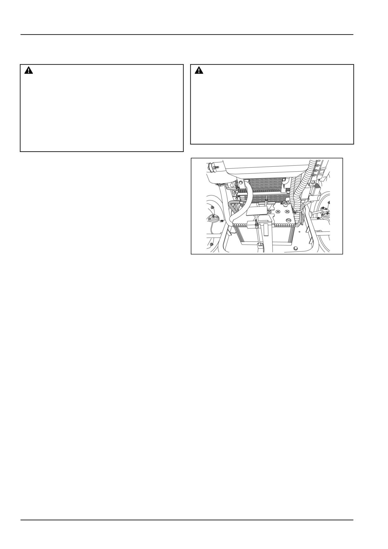
The battery is located in front of the radiator.
The battery electrolyte level should be between the mini-
mum and maximum lines provided on battery container.
If necessary, top off with distilled or de-mineralized water
until the level is correct. Do not overfill. Never use tap
water or water from rain barrel or other source.
To prevent the formation of corrosion, the terminals should
be cleaned and smeared with petroleum jelly. Do not ap-
ply grease to the battery terminals.
NOTE: Battery size - BCI group - 47 (CCA 600--850).
GNIL14TR00784AA
1
7-10
7 - MAINTENANCE
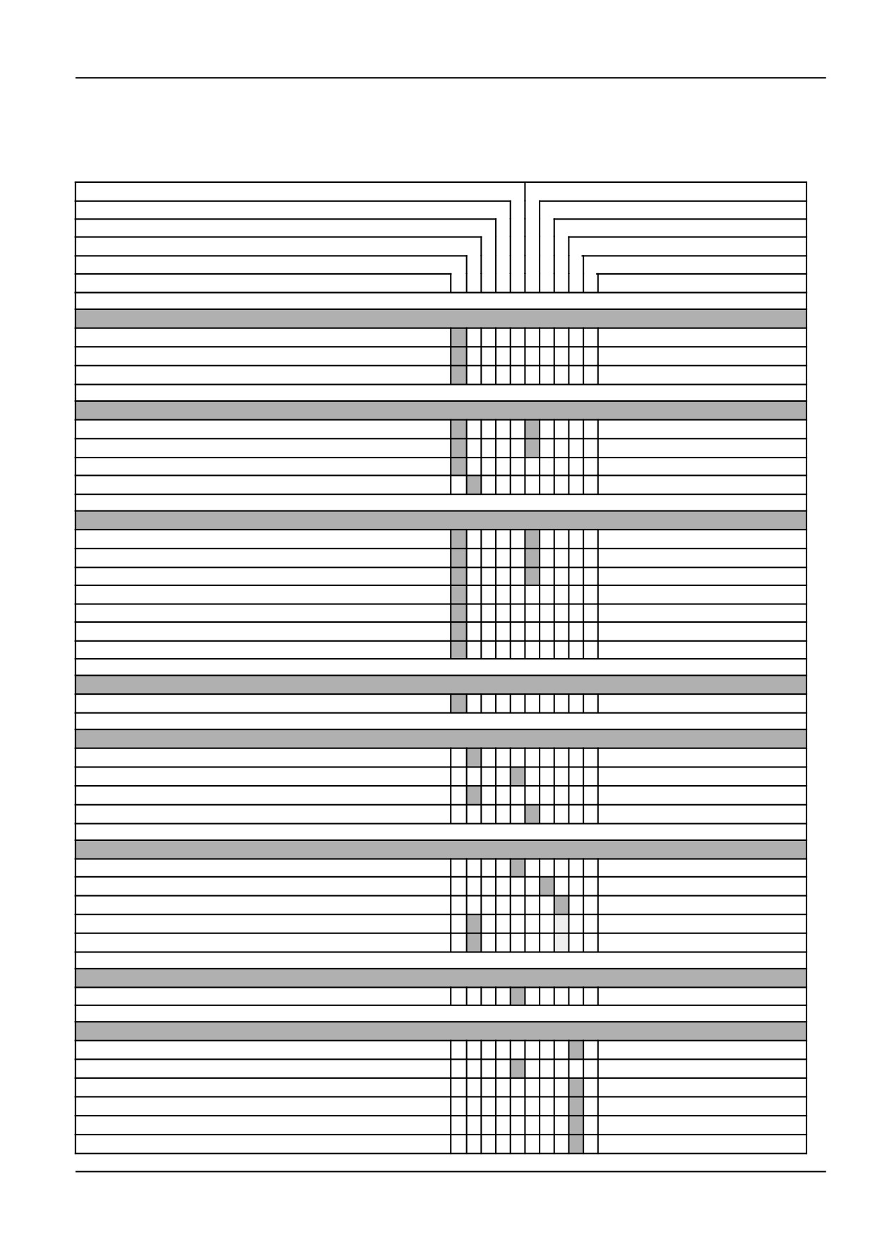
MAINTENANCE CHART
Frame - Maintenance chart
Cleaning
Adjust
Drain fluid
Grease
Lubricate
Test
Replace
Change fluid
Check
Bleed
Service points
Page no.
Every 10 hours of operation or daily
Engine oil level
7-13
Engine cooling system
7-13
Steering reservoir oil level
7-14
After the first 50 hours of operation
Clutch pedal free play
7-15
Brake pedal free play
7-15
Wheels and tires
7-15
Hydraulic oil filter
7-15
Every 50 hours
Clutch pedal free play
7-16
Brake pedal free play
7-16
Wheels and tires
7-17
Transmission or hydraulics oil level
7-17
Front axle differential oil level
7-18
Front wheel hub oil level (4WD)
7-18
Air cleaner
7-19
Every 150 hours
Battery electrolyte level
7-20
Every 300 hours
Engine oil and filter
7-20
Engine air cleaner outer element
7-22
Hydraulic oil filter
7-26
Power Take-Off (PTO) clutch
7-27
Every 600 hours
Transmission breather
7-28
Front wheel bearings - (2WD)
7-28
Fuel injectors - servicing
7-29
Fuel filter replacement
7-30
Hydraulic oil filter
7-31
Every 900 hours
Air cleaner restriction indicator
7-32
Every 1200 hours
Transmission or hydraulics oil level
7-32
Fuel tank cleaning
7-33
Engine coolant
7-34
Steering oil reservoir
7-35
Four-Wheel Drive (4WD) front axle differential oil
7-36
Four-Wheel Drive (4WD) front axle hub oil
7-36
7-11
7 - MAINTENANCE
Cleaning
Adjust
Drain fluid
Grease
Lubricate
Test
Replace
Change fluid
Check
Bleed
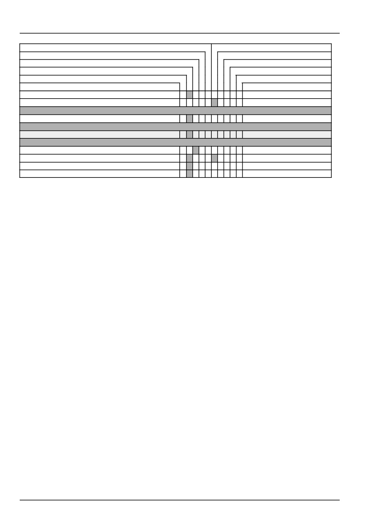
Service points
Page no.
Air filter
7-37
Power Take-Off (PTO)
7-39
Every 1800 hours
"Drive belt (type Poly-V)"
7-40
Every 4000 hours
Alternator
7-40
As required
Lubrication points
7-41
Headlights
7-44
Fuses
7-45
Bulbs
7-47
7-12
7 - MAINTENANCE
Every 10 hours of operation or daily
Engine oil level
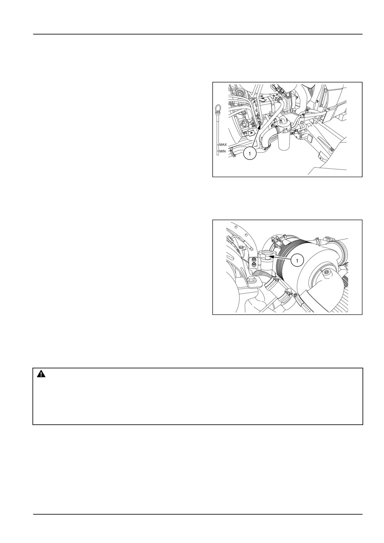
1. Before checking the oil level, ensure that the tractor is
on level ground, stop the engine and wait for a short
period to allow the oil to drain back into the sump.
GNIL14TR00519AA
1
2. Pull out the dipstick from dipstick port. (1) see figure 2
3. Check the oil level by means of the dipstick (1) see
figure 1.
4. If the level is below minimum mark, add fresh oil (1) see
figure 2 until oil level is between the two marks on the
dipstick.
GNIL14TR00523AA
2
NOTICE: Do not fill above the upper maximum line on dipstick. Excessive oil will be burned off within a short time
and give a false impression of oil consumption.
Engine cooling system
WARNING
Burn hazard!
Hot coolant can spray and scald if you remove the radiator or deaeration tank cap while the system
is hot. To remove the cap: allow the system to cool, turn the cap to the first notch, and wait for all
pressure to release. Remove the cap only after all pressure has released.
Failure to comply could result in death or serious injury.
W0367A
7-13
7 - MAINTENANCE
Peak power operation, followed by a rapid reduction
in power requirement and engine speed, may cause
the coolant to boil and be discharged from the radiator
overflow tube. Normally, this loss of coolant is small and
of little consequence, but repeated loss can significantly
lower the coolant level and necessitate topping off. An
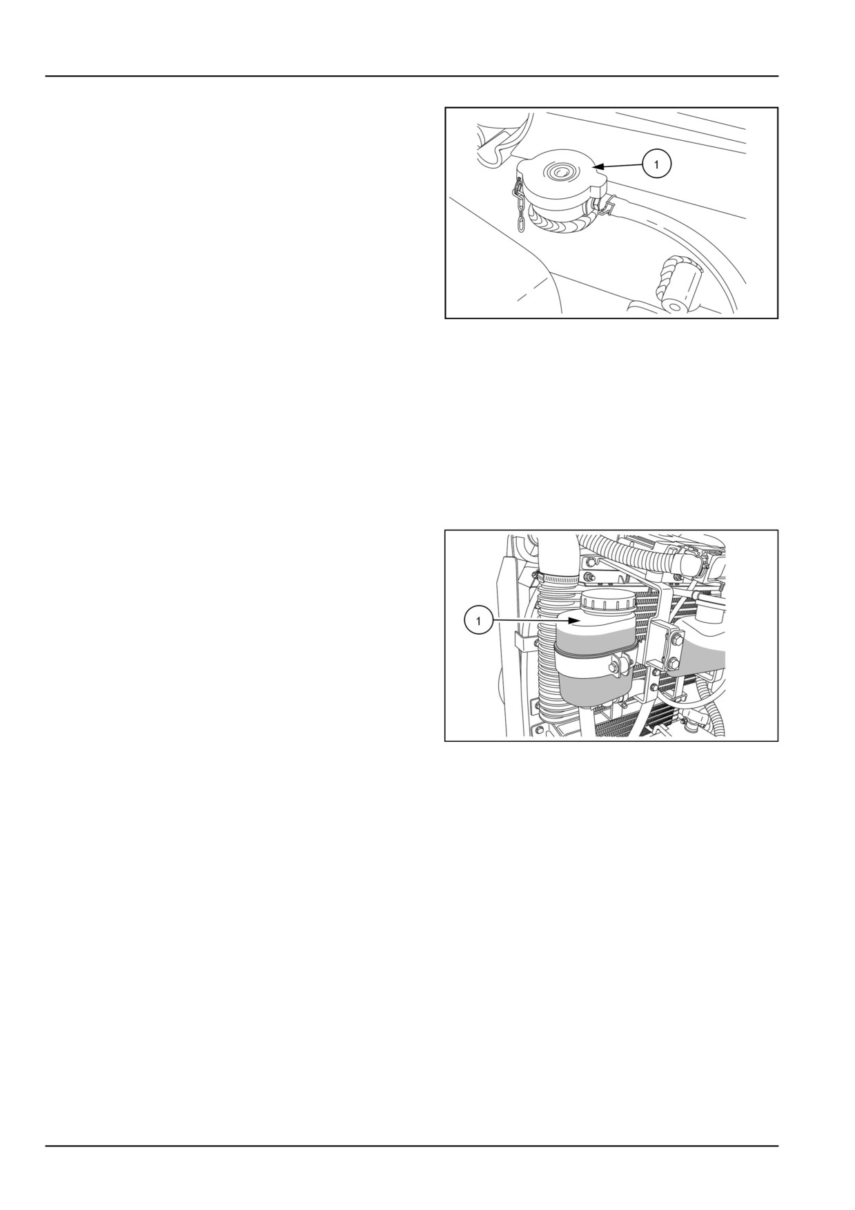
additional water tank is fitted fill the coolant in the tank
by removing tank cap (1).
GNIL14TR00517AA
1
NOTICE: Never use tractor without radiator cap (1) as this will result into boiling and hence evaporation of the engine
coolant.
Steering oil reservoir level
1. Check the oil level through the transparent reservoir
(1). .
2. If level is low, add NEW HOLLAND AMBRA MULTI G
134™ HYDRAULIC TRANSMISSION OIL as required.
3. Make sure that the breather in the cap is completely
clean.
Oil capacity 2.0 l (0.5 US gal).
GNIL14TR00518AA
1
7-14
7 - MAINTENANCE
After the first 50 hours of operation
Clutch pedal free play
1. See 7-16
Brake pedal free play
1. See 7-16
Wheels and tires
1. See 7-17
Hydraulic oil filter
1. See 7-26
7-15
7 - MAINTENANCE
Every 50 hours
Clutch pedal free play
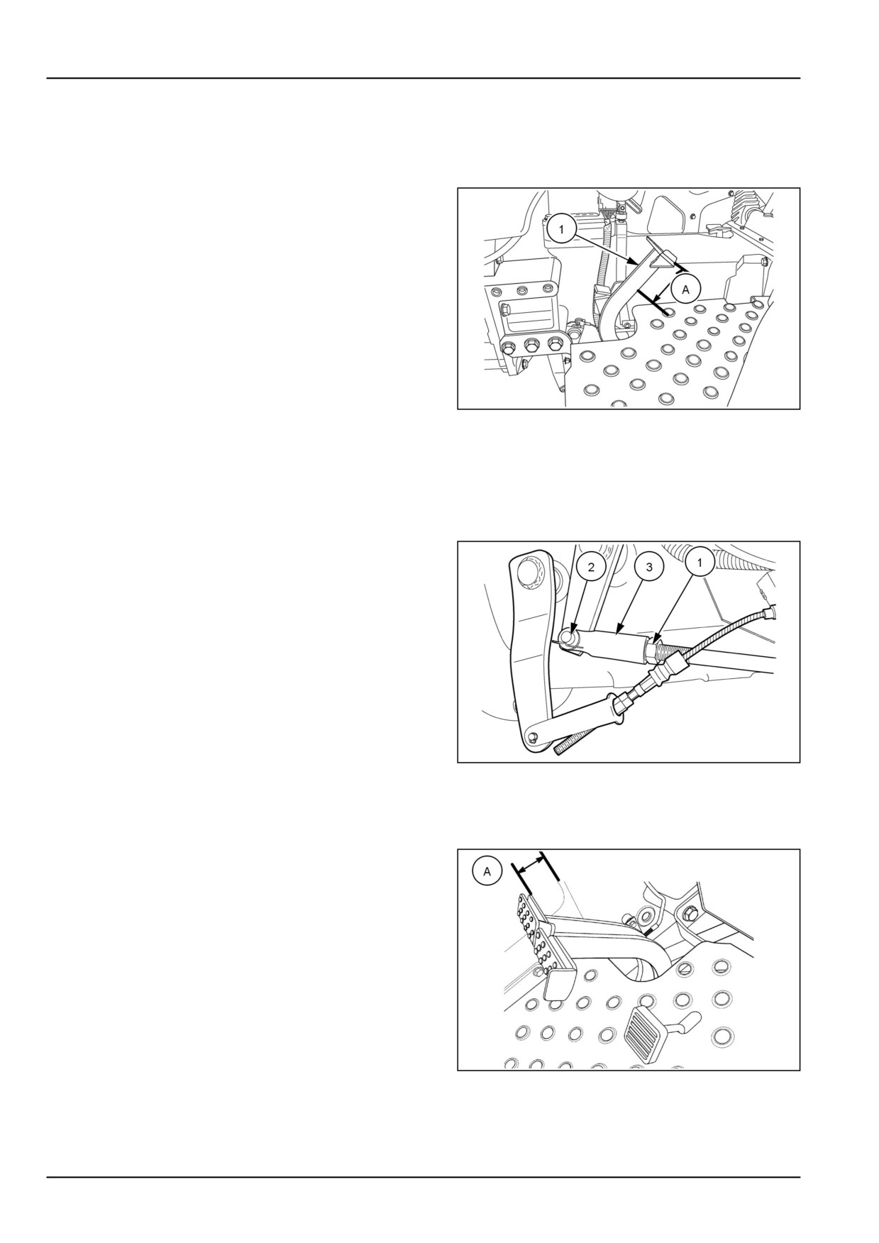
1. Check clutch free play (A) . The clutch free play should
be 35 - 40 mm (1.38 - 1.57 in) at clutch pedal (1).
86090118NN
1
2. If adjustment is required, loosen the locknut (1) remove
the split pin and clevis pin (2).
3. Turn the clevis (3) to lengthen or shorten the operating
rod, as required. Secure the clevis pin with a new split
pin and tighten the locknut.
4. Lengthening the operating rod will increase free play
and vice-versa.
86090149N
2
Brake pedal free play
1. Measure free play of the brake pedals (A) free play
should be 20 - 40 mm (0.79 - 1.57 in)
76096162N
1
2. Adjustment to each pedal linkage is made to the brake
pull rods beneath the tractor.
7-16
7 - MAINTENANCE
3. Block the wheels, front and rear, unlock the brake ped-
als and release the parking brake lever.
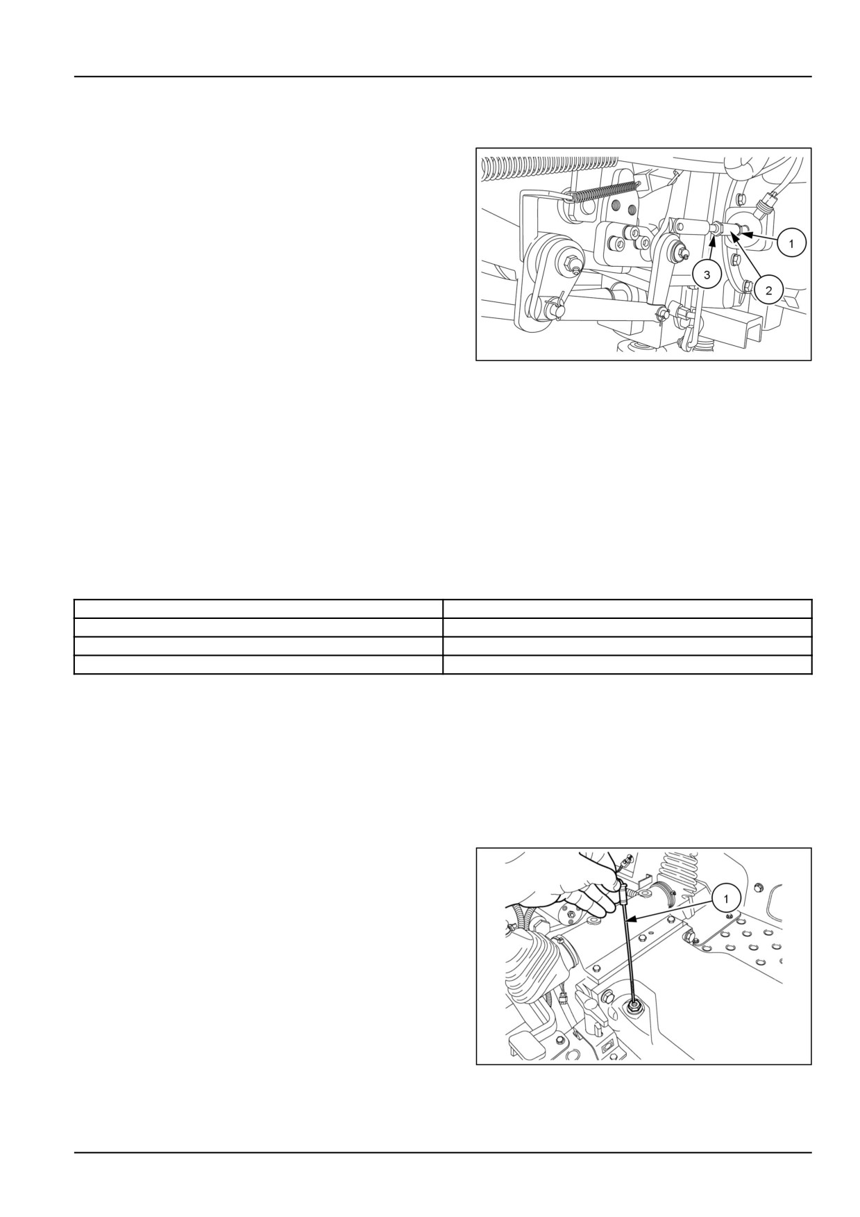
4. Loosen the locknut (1) on the brake pull rod (2) and
turn the adjuster nut (3) clockwise to reduce the play
and counter-clockwise to increase the play. .Ensure
that the pedals have same travel
GNIL14TR00520AA
2
5. Lock the brake pedals together and road test to ensure
that the brakes are adjusted equally and will stop the
tractor in a straight line.
6. Adjust thelinkages if needed to balance the brakes
Wheels and tires
1. Check the front and rear wheel nuts for tightness.
2. The specified torque values are shown in the table for
reference.
Front disc to hub bolts
123 N·m (91 lb ft)
Rear disc to hub bolts
192 N·m (142 lb ft)
Rear disc to rim nuts
239 N·m (176 lb ft)239 N⋅m (176
lb ft)
Rear wheel weight to disc
150 N·m (111 lb ft)
Tire Pressures and Condition
Check and adjust the front and rear tire pressures and
inspect the tread and side-walls for damage.
3. Adjust the tire pressures to suit the load being carried.
Transmission oil level or hydraulic oil level
1. The oil level should be between the high and low marks
on the dipstick (1).
86090135N
1
7-17
7 - MAINTENANCE
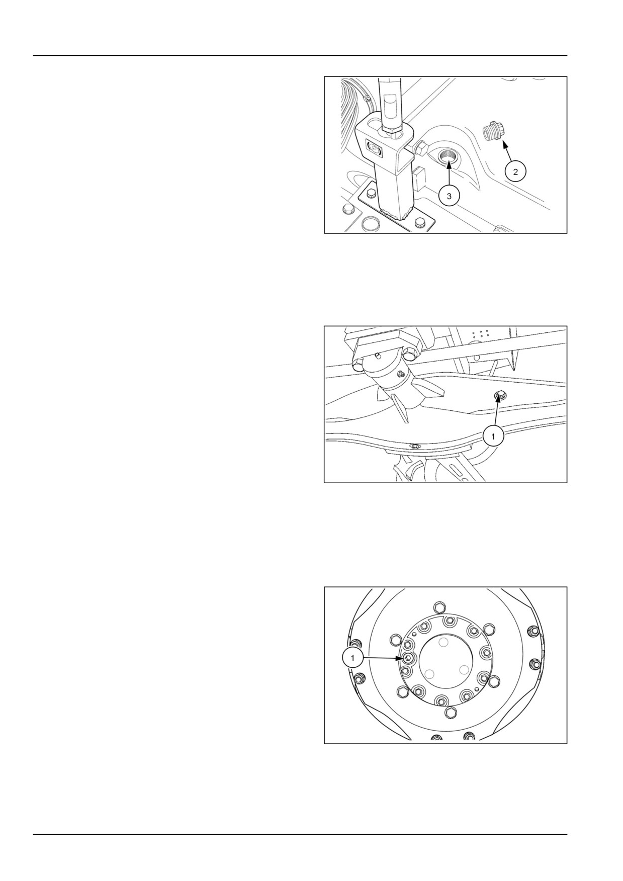
2. If necessary, remove the dipstick adapter fitting (2) and
add oil through dipstick hole (3). Add oil until level is to
upper mark on the dipstick. Do not overfill.
86096197N
2
NOTICE: Use only Genuine NEW HOLLAND AMBRA MULTI G 134™ HYDRAULIC TRANSMISSION OIL hydraulic
oil.
Front axle differential oil level
1. On Four-Wheel Drive (4WD) tractors, check oil level at
oil fill plug (1). The oil is at the correct level when oil
level is at the bottom of the fill port opening.
96096503
1
2. If oil level is low, add NEW HOLLAND AMBRA MULTI
G 134™ HYDRAULIC TRANSMISSION OIL hydraulic
oil through fill port, until correct oil level is obtained.
Front wheel hub oil level (4WD)
1. On Four-Wheel Drive (4WD) tractors, check each front
axle hub oil level with the wheel positioned so the oil
filler plug (1) is level with the center of the hub, midway
from top to bottom.
76073647N
1
2. The oil is at the correct level when the oil level is at the
bottom of the fill port opening.
7-18
7 - MAINTENANCE
3. If the oil level is low, add NEW HOLLAND AMBRA
MULTI G 134™ HYDRAULIC TRANSMISSION OIL
hydraulic oil through fill port, until correct oil level is ob-
tained.
Air cleaner
Engine air cleaner outer element - check
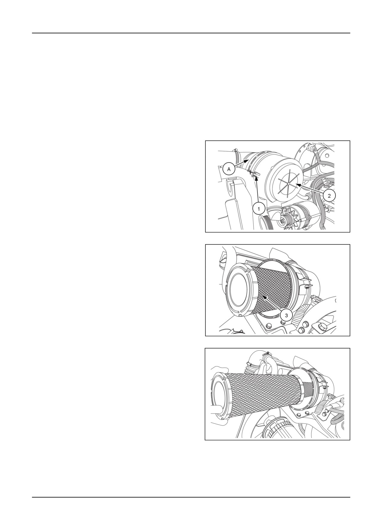
The air cleaner (A) which is located under the hood,
consists of an inner and outer paper element within a
metal casing.
1. Unlatch the three retaining clips, (1) and lift off the air
cleaner assembly cover (2).
GNIL14TR00501AA.PNG
1
2. Remove the outer element (3), from the air cleaner as-
sembly by gently twisting the end of the filter clockwise
to disengage the seal.
GNIL14TR00502AA.PNG
2
3. Then pull the filter straight out of the housing, not at an
angle.
GNIL14TR00503AA.PNG
3
7-19
7 - MAINTENANCE
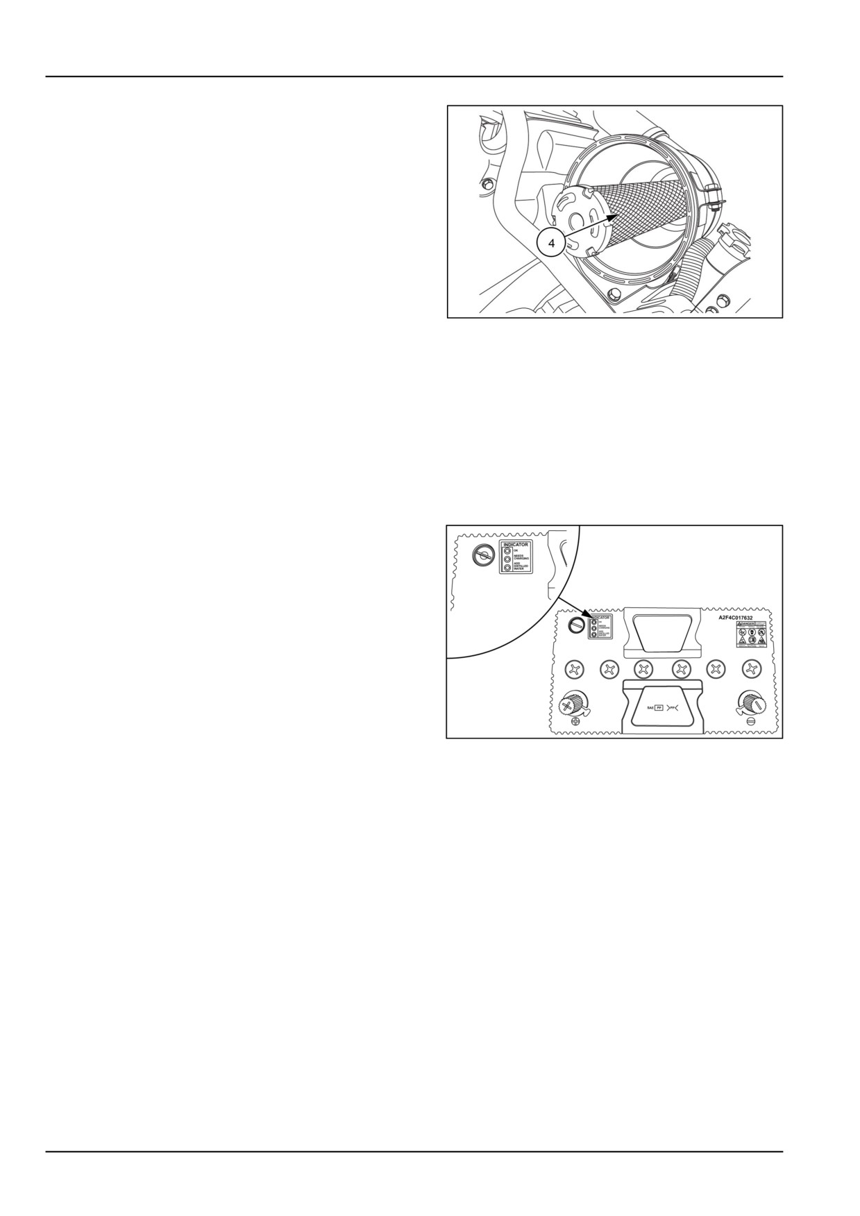
4. Make sure that the inner element (4) remains in place
GNIL14TR00504AA.PNG
4
NOTICE: Do not disturb or remove the inner element.
Every 150 hours
Battery electrolyte level
1. Battery is located in front of the radiator. Battery elec-
trolyte level should be between min. and Max. lines
provided on battery container.
2. Battery has a feature “Magic Eye” - a transparent win-
dow on top of battery which indicates the condition of
battery based on the color indication shown.
Green - Indicates battery is OK
Yellow - Indicates battery requires charging
Red - Indicates distilled water needs to be added.
GNIL14TR00589AA
1
3. If necessary, top up with distilled or demineralized wa-
ter until the level is correct. Do not overfill. Never use
tap water or water from rain barrel or other source.
4. To prevent formation of corrosion, terminals should be
cleaned and smeared with petroleum jelly (Vaseline)
only. Do not apply grease to the battery terminals.
NOTICE: In the event that battery is severely discharged, such that the terminal voltage is below 7 V, recovery will
require a special charging procedure, Contact your authorized dealer.
Every 300 hours
Engine oil and filter
Engine oil and filter replacement
1. Warm the engine to operating temperature.
2. Park the tractor on level ground.
3. Shut off the engine.
7-20
7 - MAINTENANCE
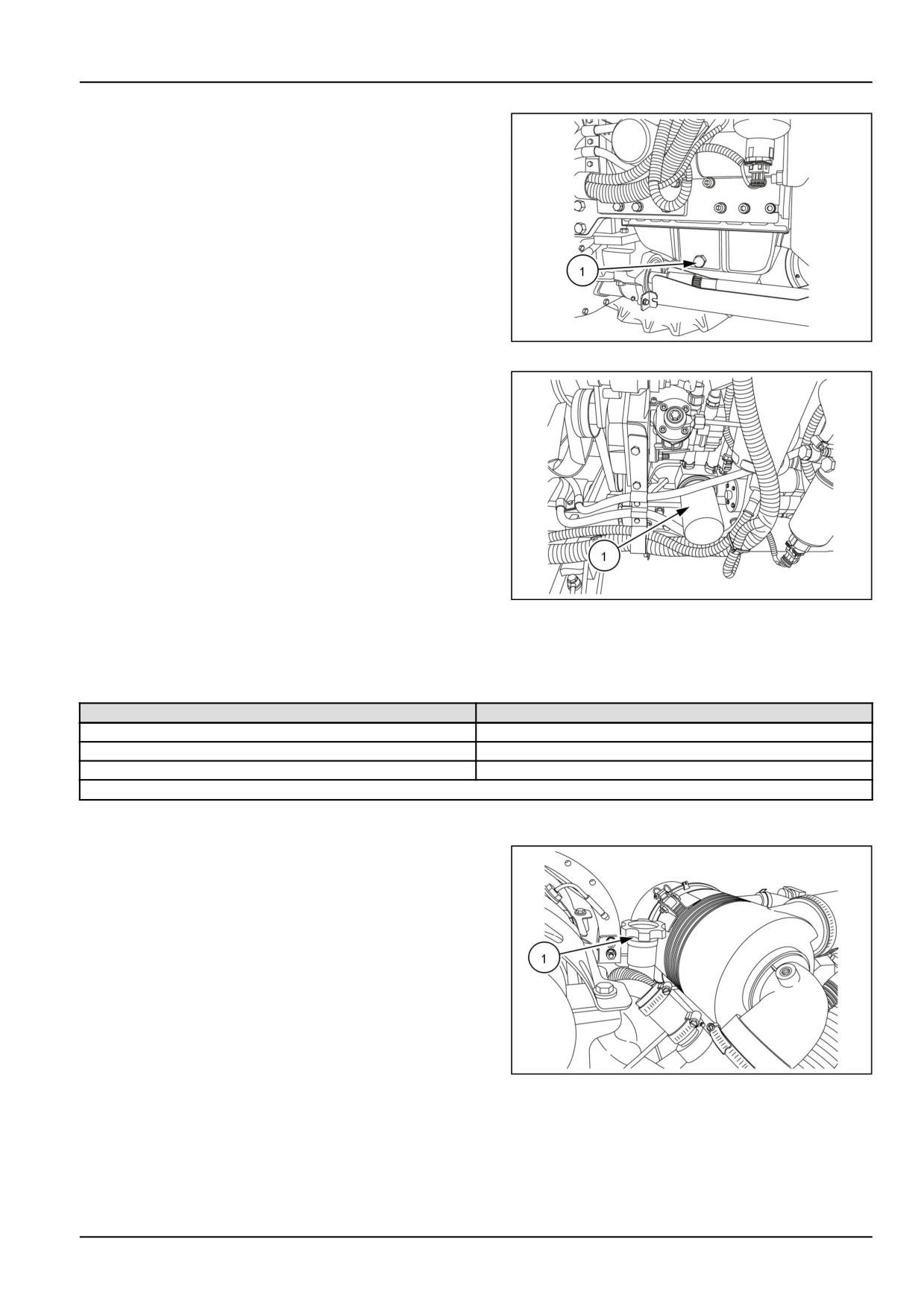
4. Remove both drain plugs (1) and collect the oil in a
suitable container.
GNIL14TR00522AA
1
5. Remove and discard the engine oil filter (1).
6. Clean the filter mounting surface before installing new
filter.
7. Lubricate the seal of new filter with clean engine oil.
8. Install the new filter, tighten filter until the seal meets the
mating surface, then tighten additional 3/4 of a turn. Do
not over tighten.
GNIL14TR00521AA
2
NOTICE: Always change engine oil filter, when changing
engine oil.
Recommended Oils
Ambient Temperature
Recommended Oil
15 - +45 °C
SAE
10W 40
-30 - +45 °C
SAE
5W 40
-30 - +15 °C
SAE
5W 30
* Tractors are originally shipped with 10W-30 oil.
NOTE: The combined capacity of the engine crankcase and oil filter is 6.3 L (1.7 US gal) for
9. Replace the drain plugs and refill the engine with clean
oil at filler cap (3).
10. Run the engine for a minute or so to circulate the oil,
and shut off the engine.
11. Add clean oil, as necessary, until the oil level is be-
tween minimum and maximum marks on the dipstick.
NOTICE: Do not fill above the maximum mark on the dip-
stick. Excessive oil will be burned off within a short time
and give a false impression of oil consumption.
GNIL14TR00523AA
3
7-21
7 - MAINTENANCE
Engine air cleaner outer element
Engine air cleaner outer element
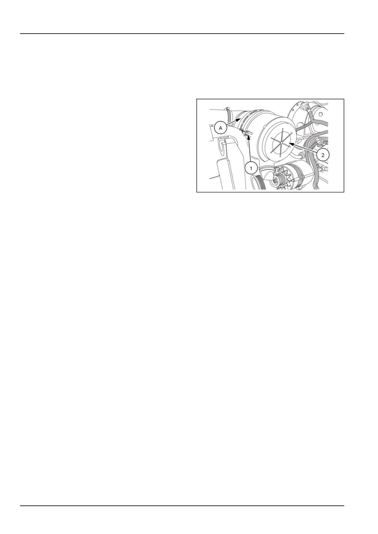
The air cleaner (A) which is located under the hood,
consists of an inner and outer paper element within a
metal casing.
1. Unlatch the three retaining clips, (1) and lift off the air
cleaner assembly cover (2).
GNIL14TR00501AA.PNG
1
7-22
7 - MAINTENANCE
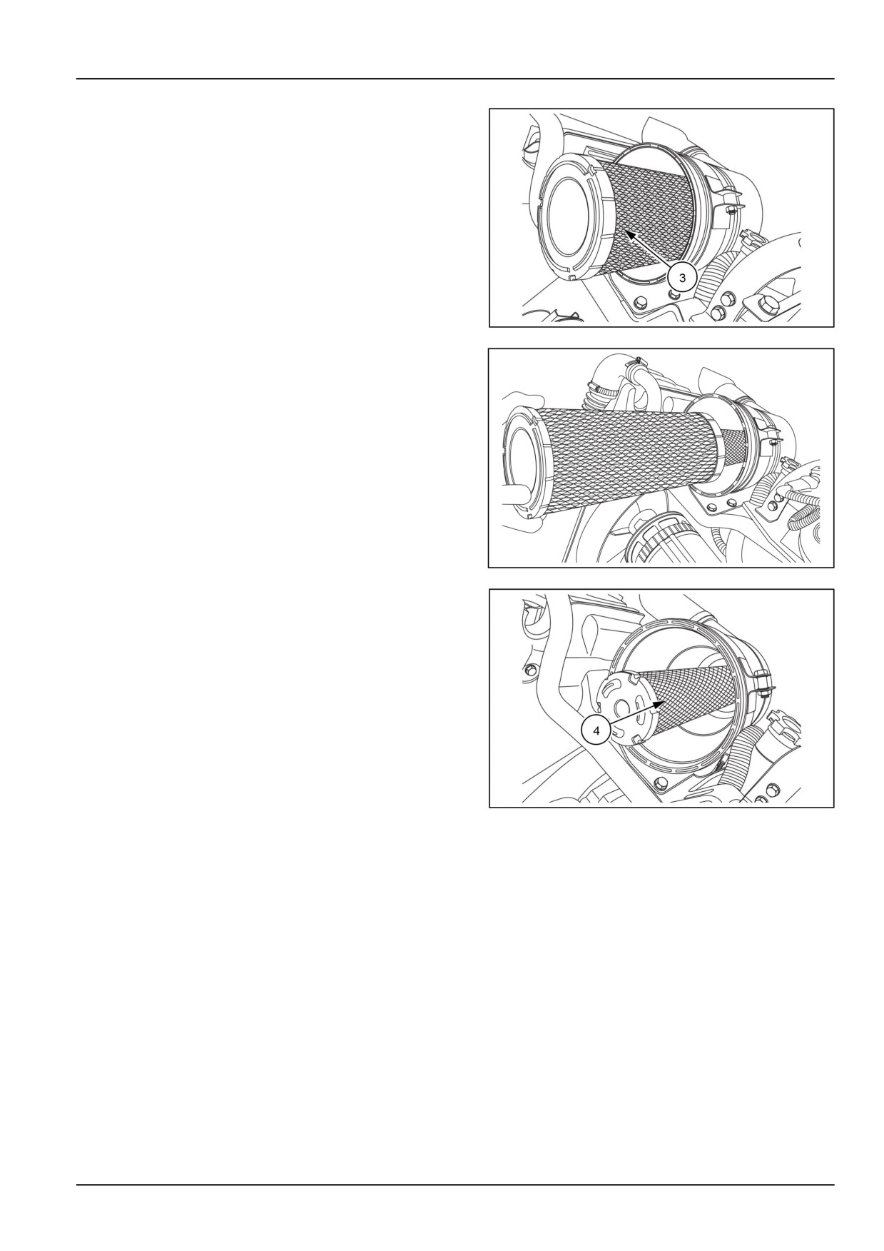
2. Remove the outer element (3). from the air cleaner as-
sembly by gently twisting the end of the filter clockwise
to disengage the seal. Then pull the filter straight out
of the housing, not at an angle.
GNIL14TR00502AA.PNG
2
GNIL14TR00503AA.PNG
3
GNIL14TR00504AA.PNG
4
NOTICE: Do not disturb or remove the inner element.
3. Make sure the inner element (4) remains in place.
4. Clean the outer element using either method A, or
method B, depending on the element's condition.
NOTICE: The outer element may be dry cleaned (methods A or B ) every 300 h or when warning bulb glows (which
ever is earlier). The outer element should be replaced after four cleanings or maximum of 1200 h. The inner element
should be replaced when the outer element is replaced or every 1200 h
7-23
7 - MAINTENANCE
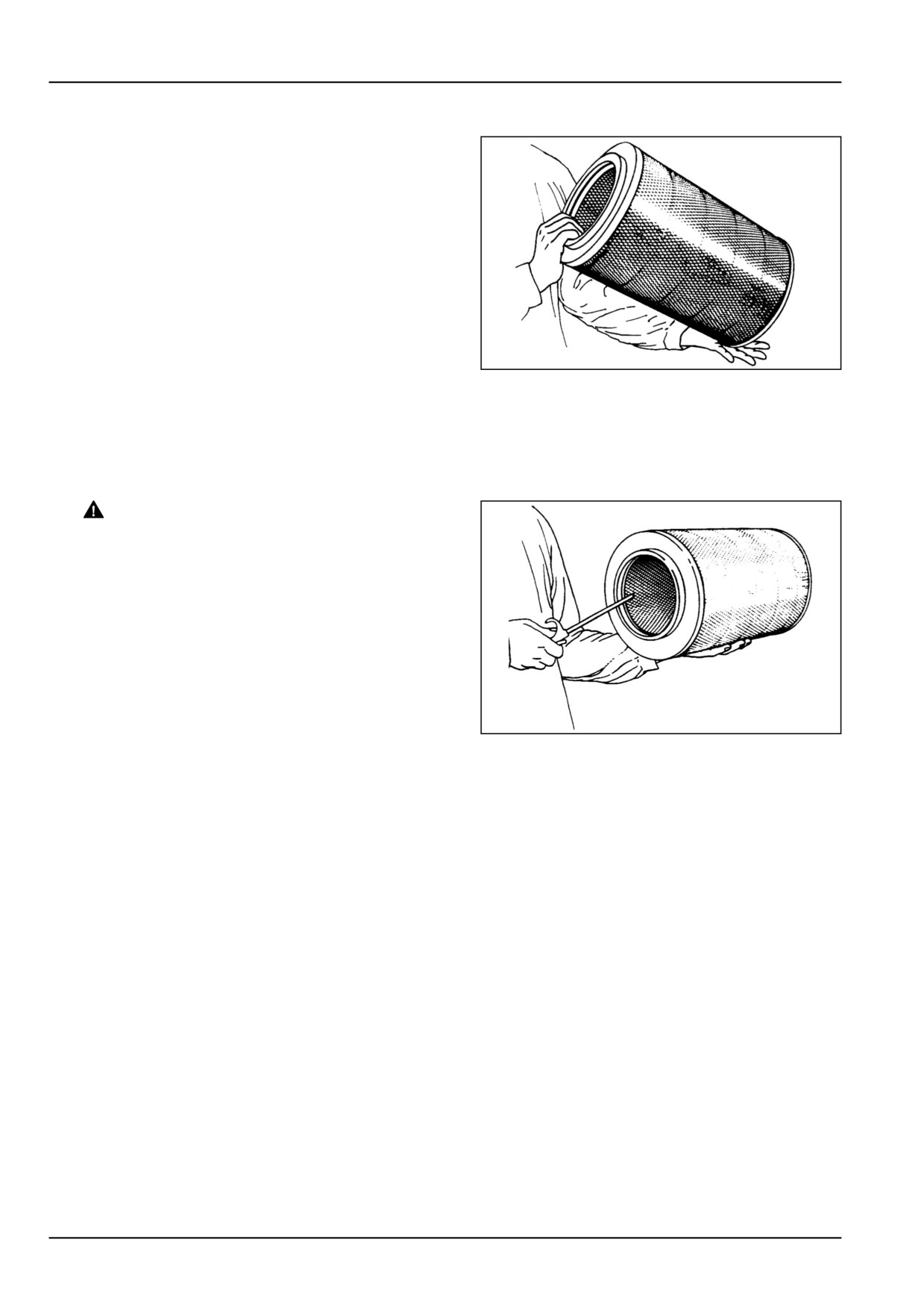
Method A
1. Lightly tap the end of the element against the palm on
the hand.
20108807
5
NOTICE: Do not tap the element against a hard surface as this will damage the element.
Method B
1.
WARNING
Flying debris!
Compressed air can propel dirt, rust, etc. into
the air. Wear eye and face protection when us-
ing compressed air.
Failure to comply could result in death or seri-
ous injury.
W0307A
Use compressed air, not exceeding
131.0 kPa
(19.0 psi).
20108808
6
2. Insert the air line nozzle inside the element
3. Hold the nozzle at a distance from the element and
blow the dust from the inside through the element to
the outside.
NOTICE: Under dusty conditions, clean outer element more often than 300 h Loss of engine power, excessive smoke,
and the illumination of air cleaner restiction light indicates the possible clogging of the filter.
Inspection of the outer element
1. Examine the element for damage by placing a light in-
side the element. Discard the element if pin pricks of
light can be seen or if there are areas where the paper
appears thin.
2. Check the element material for bunching, the metal
casing for distortion and rubber sealing for damage.
Discard the filter if the filter is damaged.
3. Clean the inside of air cleaner housing using a damp,
lint free cloth on a probe. Do not damage the inner filter
element. Make sure that the inner end of housing is
clean and smooth, to ensure a good seating for rubber
seal on the element.
7-24
7 - MAINTENANCE
4. Install cleaned outer element or a new outer element
by gently pushing the outer element inside the housing
while rotating the filter in a clockwise direction.
5. While installing the cover make sure that the dust cup
(1) is facing downward.
GNIL14TR00501AA.PNG
7
6. Check all the air intake hoses for damage. Replace the
damaged hoses.
7. Check air intake hoses clamps for tightness, tighten
clamps if needed.
Inspection of inner element
1. Only remove the inner element for replacement. The
inner element should never be cleaned
2. The inner element should be replaced when replacing
outer element or every 1200 h, hours whichever is ear-
lier.
3. Follow the similar instructions of removing and fitting
outer element from casing to replace the inner element.
7-25
7 - MAINTENANCE
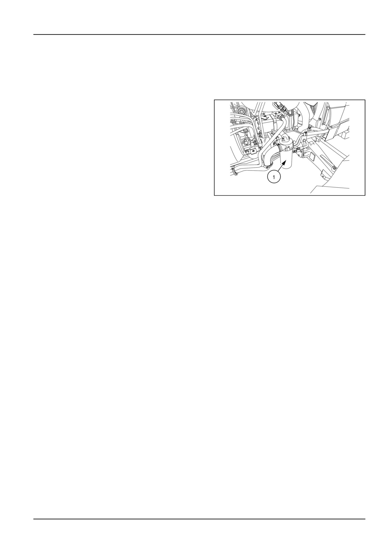
Hydraulic oil filter
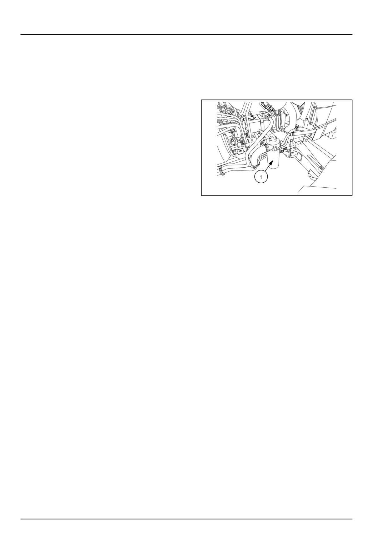
The hydraulic oil filter (1) is installed on the right-hand
side of the engine.
1. Clean the area around the filter. Remove the filter and
discard.
2. Clean the inlet gallery and the face of the filter mount-
ing.
GNIL14TR00506AA
1
3. Apply clean oil around the rubber seal of the new filter
and install on the tractor.
4. Tighten until the faces just meet, then tighten the hy-
draulic oil filter further 3/4 of a turn. Do not over tighten.
7-26
7 - MAINTENANCE
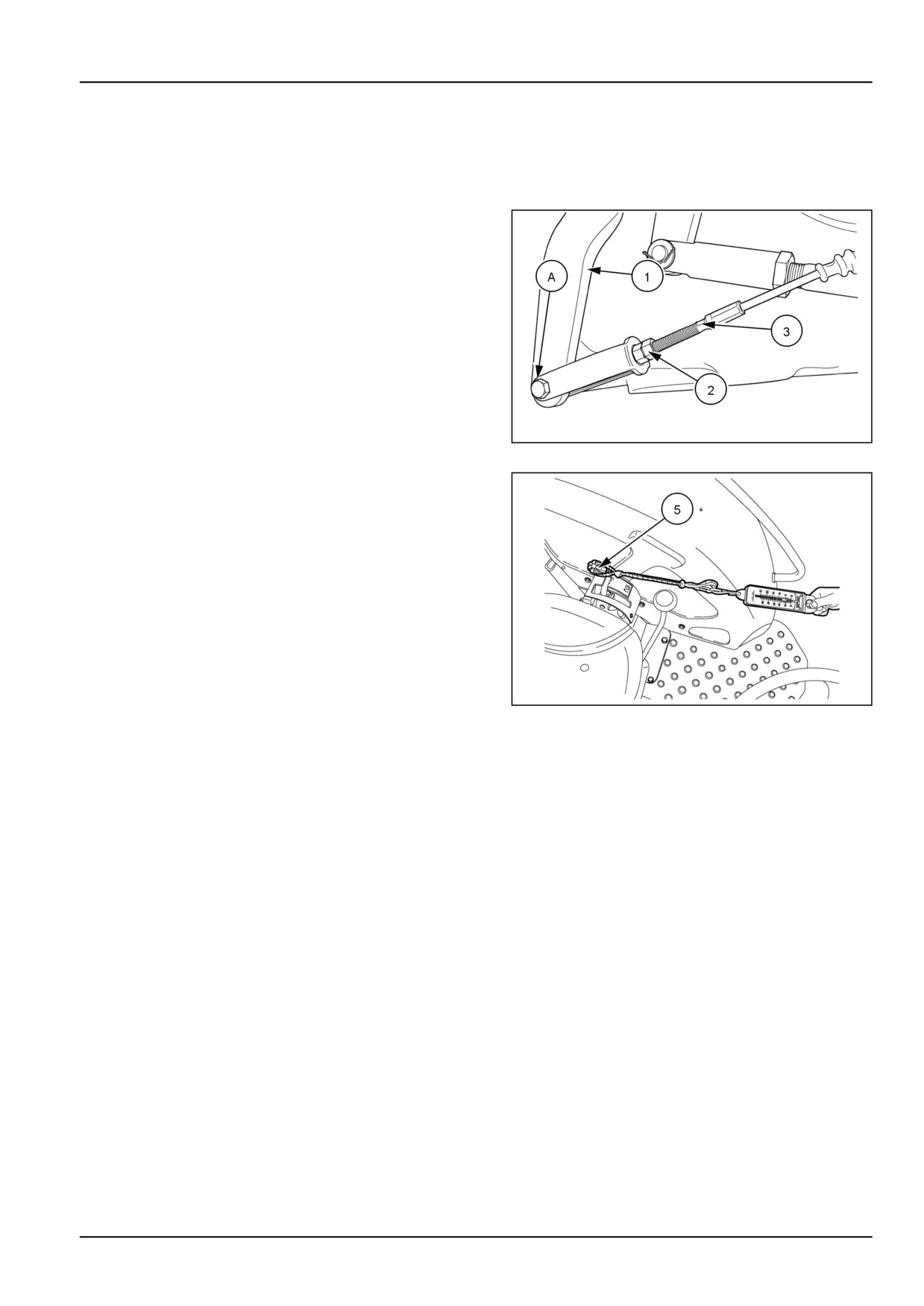
Power Take-Off (PTO) clutch
The Power Take-Off (PTO) clutch engagement pres-
sure needs to be checked and adjusted to prevent slip-
page of the PTO during operation under load.
1. When the PTO clutch linkage is properly adjusted, the
PTO lever (1) should have 2 mm (0.079 in) of free play
at the pin (A) when the PTO handle is in the "OFF"
position.
2. If the free play of lever is not correct, adjust the free play
by loosening jam nut (2) and shortening or lengthening
cable, (3).
56061331N
1
3. Use a spring scale (4) to measure the force needed
to fully engage the PTO handle (5). Proper amount of
force at end of handle to fully engage the PTO clutch is
125 - 142 N (28 - 32 lb)
86090136N
2
NOTICE: When PTO clutch linkage is properly adjusted, the total cable travel should be 21 mm (0.83 in) while en-
gaging and disengaging the PTO clutch.
7-27
7 - MAINTENANCE
Every 600 hours
Transmission breather
1. Remove breather (1) and wash with cleaning fluid.
Check for the free movement of ball inside the breather
by shaking. If the ball is jammed, replace the breather
with a new breather.
86090127N
1
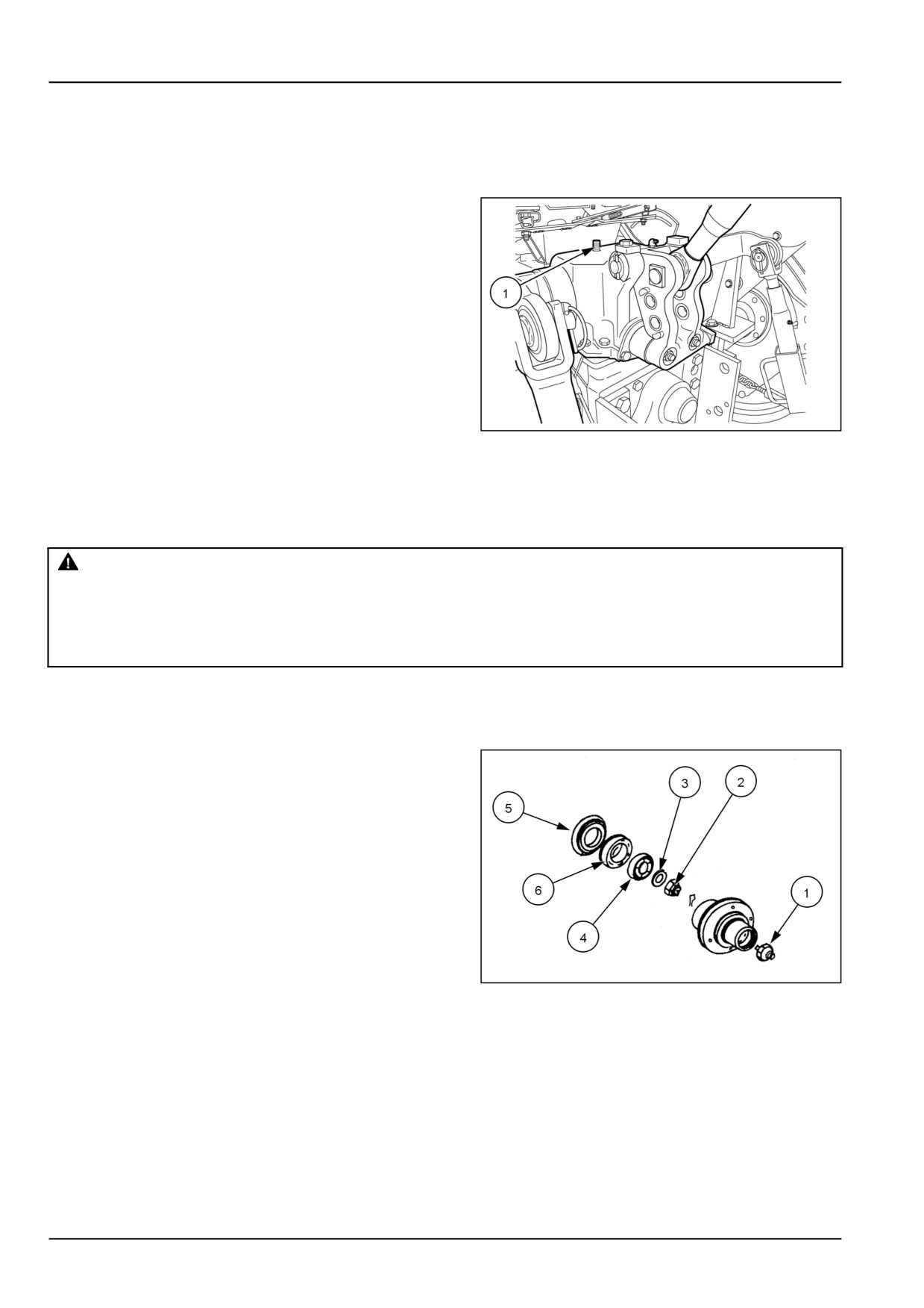
Front wheel bearing - Two-Wheel Drive (2WD)
Clean, grease and adjust wheel bearings
WARNING
Overturning hazard!
Always try to park the machine on firm level ground. Avoid parking on slopes. Block the wheels in
both directions.
Failure to comply could result in death or serious injury.
W0051A
1. With the parking brake applied on a flat surface, jack up
and support one front wheel. Block the wheels before
jacking.
2. Remove the cap (1), nut (2), thrust washer (3), and the
outer bearing (4).
3. Remove the complete wheel and hub assembly and
remove the grease seal (5) and inner bearing (6).
20108810
1
4. Thoroughly clean all parts and allow to dry.
Reassembly
1. Inspect the bearings and both bearing cups in the wheel
hub for discoloration and wear.
2. Replace bearings and cups as needed.
3. Pack the bearings and space between the two bearing
cups with grease. Also coat the wheel spindle with
grease.
7-28
7 - MAINTENANCE
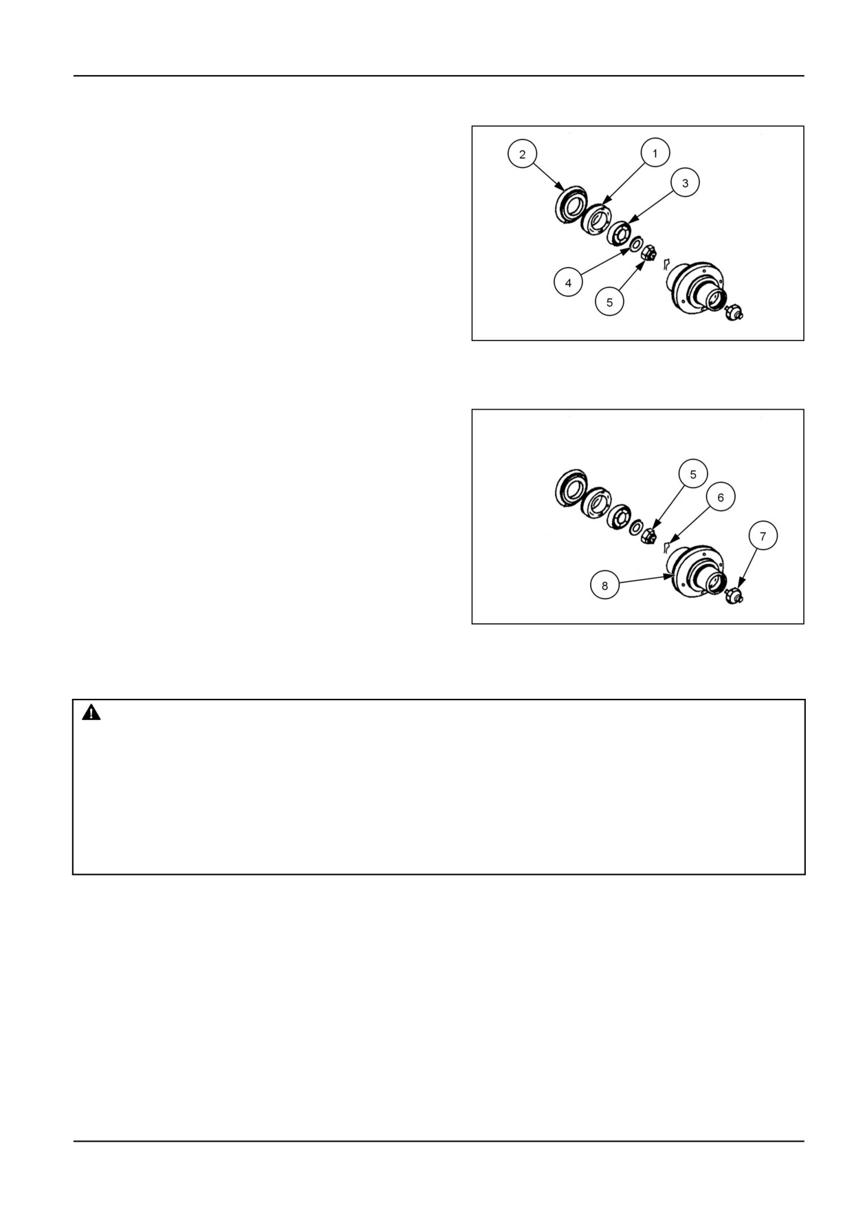
NOTE: Reassemble using a new grease seal.
4. Install inner bearing (1), grease seal (2), outer bearing
(3), thrust washer (4), and castle nut (5).
20108810
2
5. Tighten the castle nut (5),to while rotating the wheel,
until some resistance is felt.
6. Loosen the castle nut until the next slot aligns with the
cotter pin hole in the axle. Install the cotter pin (6).
7. Install the cap (7) onto the wheel hub (8).
NOTICE: Correct bearing pre-load settings are very impor-
tant. Incorrect setting may lead to premature wear of the
bearings and tires. Please contact your Authorized Dealer
if you have questions on bearing pre-load.
8. Repeat the procedure for the other wheel.
20108810
3
Fuel injectors - servicing
CAUTION
Escaping fluid!
Hydraulic fluid or diesel fuel leaking under pressure can penetrate the skin and cause infection or
other injury. To prevent personal injury: Relieve all pressure before disconnecting fluid lines or per-
forming work on the hydraulic system. Before applying pressure, make sure all connections are tight
and all components are in good condition. Never use your hand to check for suspected leaks under
pressure. Use a piece of cardboard or wood for this purpose. If injured by leaking fluid, see your
doctor immediately.
Failure to comply could result in minor or moderate injury.
C0104A
1. The fuel injectors should only be cleaned and adjusted
by an Authorized dealer.
7-29
7 - MAINTENANCE
Fuel filter replacement
Replacing the fuel filter
WARNING
Pressurized system!
Never attempt to drain fluids or remove filters when the engine is running. Turn off the engine and
relieve all pressure from pressurized systems before servicing the machine.
Failure to comply could result in death or serious injury.
W0905A
NOTICE: Change the diesel fuel filter after 600 operating hours.
Changing the fuel pre-filter
1. Allow engine to cool before performing any mainte-
nance on the engine.
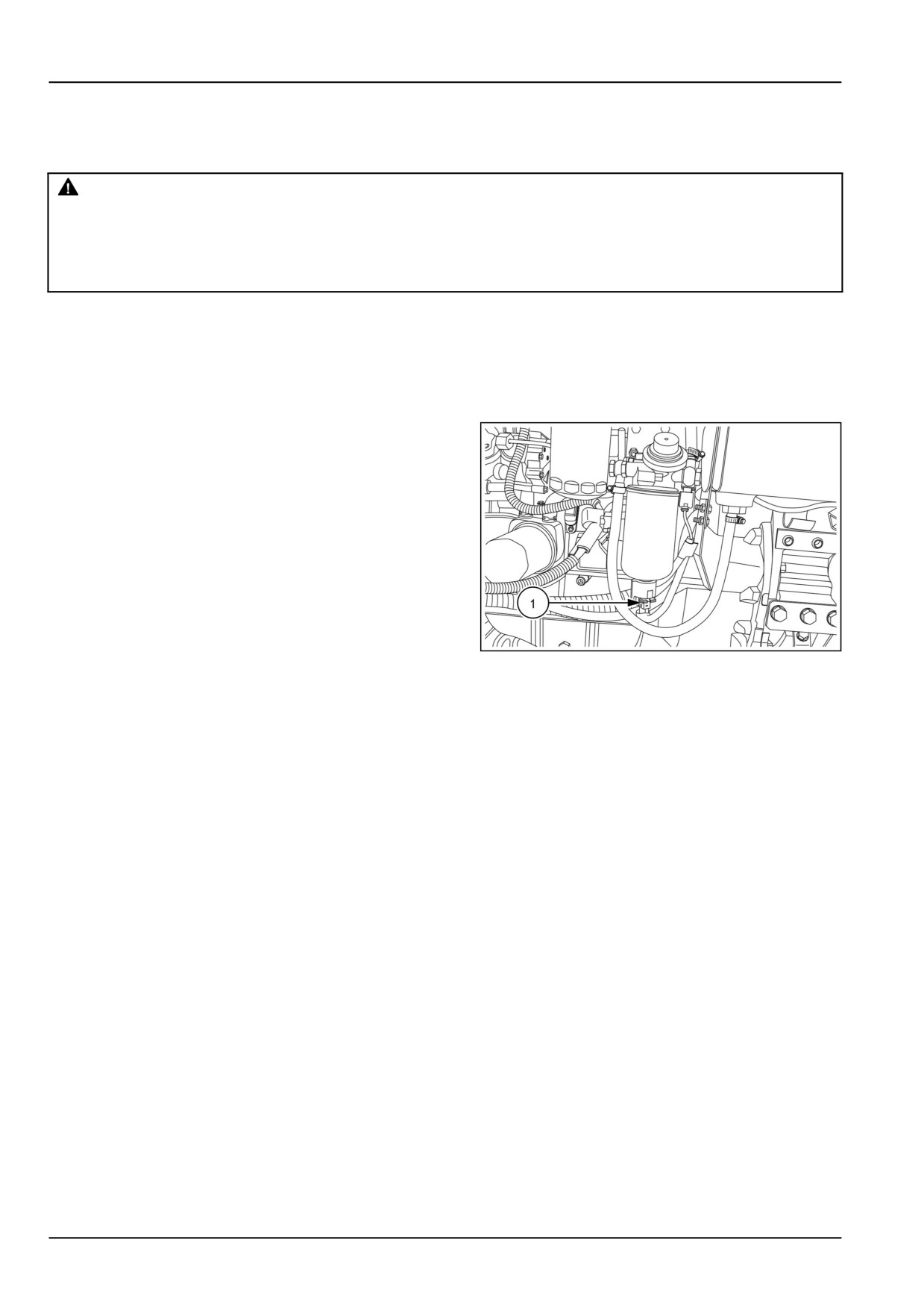
2. Remove the electrical connector (1) from the bottom of
the fuel pre-filter.
3. Place a container below the fuel pre-filter to collect any
fuel that drains out during filter removal.
4. Remove the sensor from the bottom of the fuel pre-filter.
5. Remove the fuel pre-filter from filter base
6. Fill new fuel pre-filter with diesel fuel.
7. Lubricate the fuel pre-filter gasket before installation.
8. Install new filler onto fuel pre-filter base.
GNIL14TR00591AA
1
9. Bleed air from fuel system by:
a. Loosing the bleed screw located on fuel filter base.
b. Actuate the hand pump until fuel free of any air
bubbles follow from the bleed screw.
c. Tighten the bleed screw.
NOTE: If any fuel leaks are found, stop the engine immediately and contact a service workshop.
7-30
7 - MAINTENANCE
Hydraulic oil filter
The hydraulic oil filter (1) is installed on the right-hand
side of the engine.
1. Clean the area around the filter. Remove the filter and
discard.
2. Clean the inlet gallery and the face of the filter mount-
ing.
GNIL14TR00506AA
1
3. Apply clean oil around the rubber seal of the new filter
and install on the tractor.
4. Tighten until the faces just meet, then tighten the hy-
draulic oil filter further 3/4 of a turn. Do not over tighten.
7-31
7 - MAINTENANCE
EVERY 900 HOURS
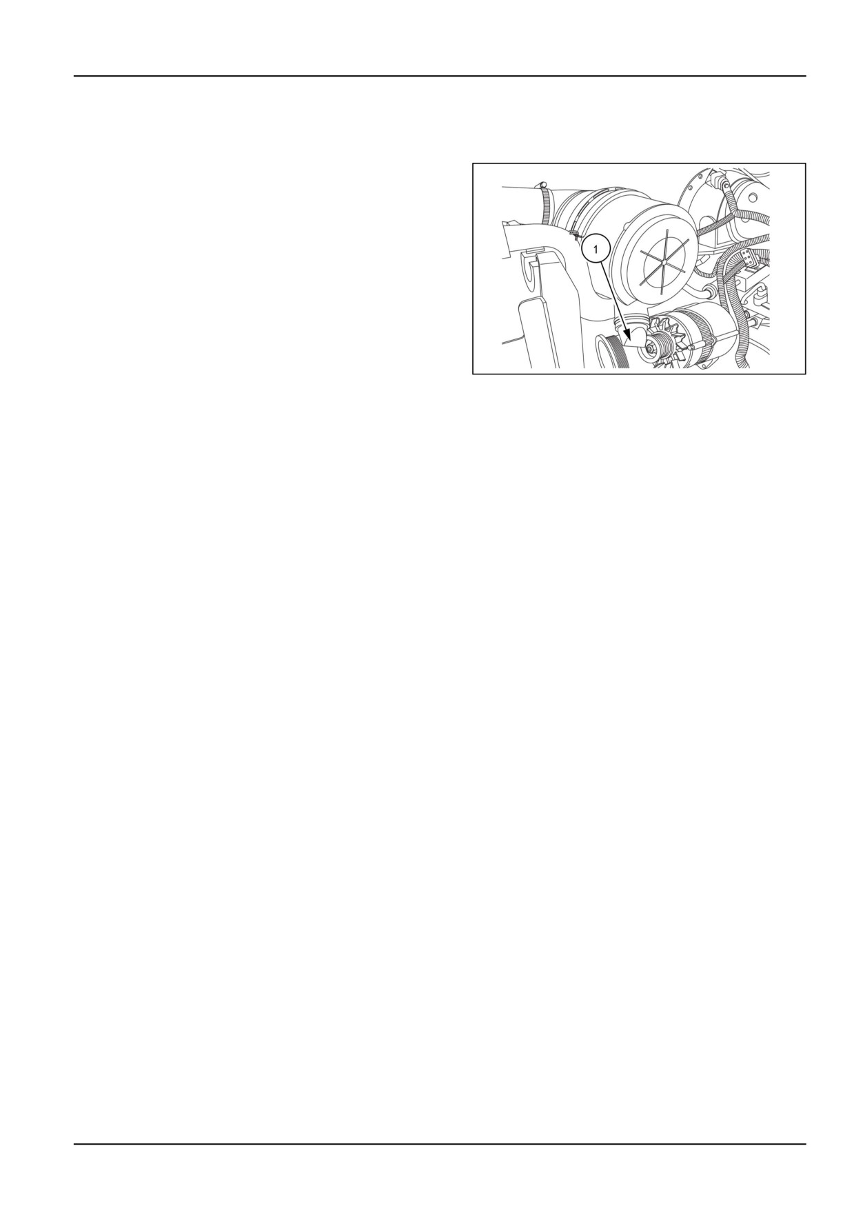
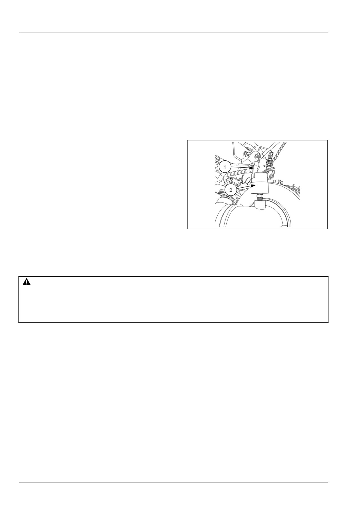
Air cleaner restriction indicator
1. Air cleaner restriction light indicates that air cleaner is
blocked.
2. Clean the air cleaner outer element whenever light
glows.
3. If the air cleaner restriction indicator illuminates contin-
uously, check the air cleaner restriction sensor. (1).
4. Disconnect the Electrical connection
5. Unscrew the air cleaner restriction sensor (2) from air
inlet pipe. Inspect the air cleaner restriction sensor.
Replace the air restriction sensor indicator if necessary.
GNIL14TR00524AA
1
Every 1200 hours
Transmission/hydraulics oil level
WARNING
Burn hazard!
Be very careful to avoid contact with hot fluids. If fluid is extremely hot, allow it to cool to a moderately
warm temperature before proceeding.
Failure to comply could result in death or serious injury.
W0362A
1. Prior to changing oil, run the engine and operate the
hydraulic/transmission system until the oil is warm.
2. Park the tractor on level ground, lower the three point
linkage and stop the engine. Engage the parking brake
and block wheels.
7-32
7 - MAINTENANCE
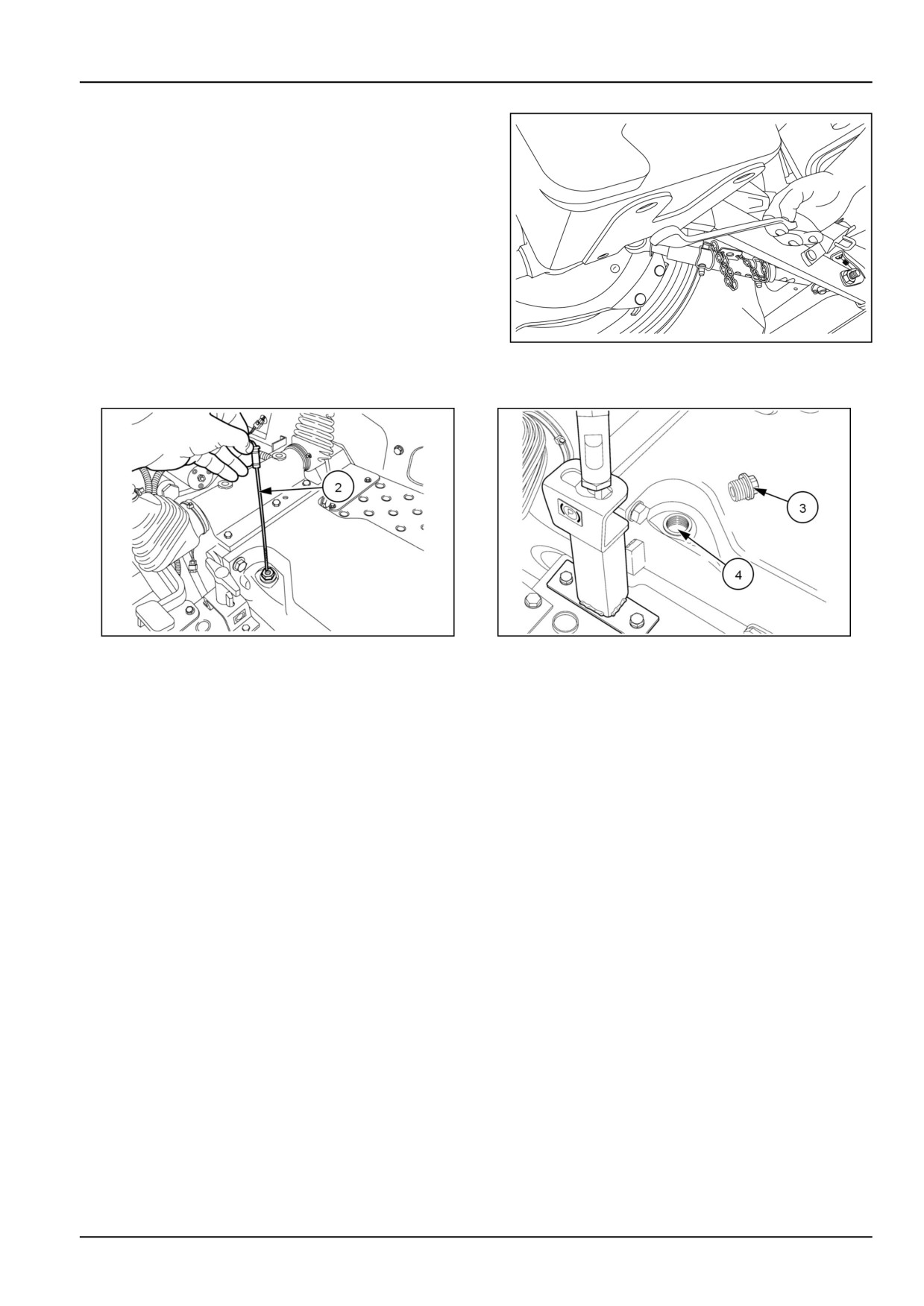
To drain the transmission oil:
1. Remove the drain plug. Drain the oil in to a suitable
container.
2. Reinstall the drain plug after the oil is drained.
3. Remove the dipstick (2) and adapter fitting (3) and
add oil through dipstick hole (4). Add oil until level
is to upper mark on the dipstick. Do not overfill.
4. Start the engine and operate the hydraulic system.
Fully raise and lower the three point linkage.
5. Shut off the tractor and wait for few minutes, for
checking the system for leaks.
GNIL14TR00564AA
1
6. Check the oil level. The oil level should be between
the two marks on dipstick.
86090135N
2
86096197N
3
NOTICE: Do not fill above the top mark.
Transmission/Rear Axle Oil Capacity
Capacity
25 l (6.6 US gal)
Oil Type:
NEW HOLLAND AMBRA MULTI G 134™ HYDRAULIC
TRANSMISSION OIL
Fuel tanks - Cleaning
1. Clean the fuel tank once in a year or at every 1200 h
which ever is earlier. For further details contact your
authorized dealer
7-33
7 - MAINTENANCE
Engine coolant
WARNING
Hot liquid under pressure!
Service when cool.
Failure to comply could result in death or serious injury.
W1187A
NOTICE: It is essential that a genuine approved pressure cap is used. If the cap is misplaced or damaged, obtain a
replacement from your Authorized NEW HOLLAND Dealer.
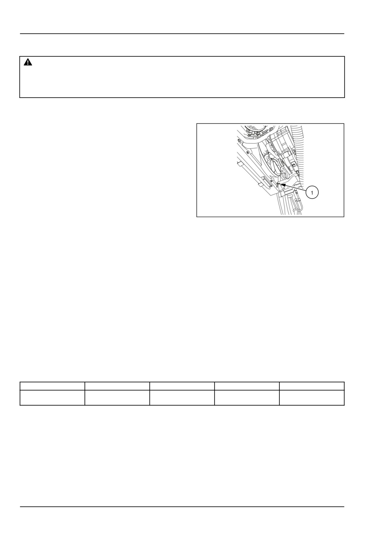
1. Open the radiator drain plug (1) and allow the coolant
to drain.
(Drain cock is on the rear, left-hand side of
the radiator). Remove the radiator pressure cap to in-
crease the drainage rate.
GNIL14TR00525AA
1
2. After draining, flush the cooling system with clean water
through the radiator filler. When the flushing process is
complete, refill the cooling system with a 50/50 solu-
tion of ethylene glycol antifreeze and water through the
radiator until the coolant is 20 mm (0.79 in) below the
neck of the radiator tank. Re-install the pressure cap.
NOTE: To avoid trapping air in the system, fill the radiator as slowly as possible thereby allowing any formation of air
pockets to disperse.
NOTE: The coolant level may drop as the coolant is pumped around the cooling system.
3. If the engine is not going to be operated immediately
following this coolant change, run the engine for one
hour to ensure that the water is distributed throughout
the cooling system. Allow the engine to cool and make
a final check to ensure that the water level is satisfac-
tory.
4. For cold climate (below freezing point), add a quality
anti-freeze solution. Add the solution to radiator in ad-
dition to water as follows:
Degrees C
-5
-5 to -18
-18 to -25
-25 to -37
% volume of
25
30
40
50
Anti-freeze
Cooling System Capacity
8.0 L (8.5 US qt)
7-34
7 - MAINTENANCE
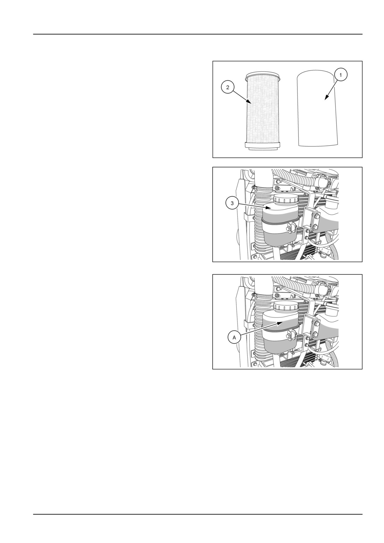
Steering - Change fluid
1. Press and remove the plastic container (1) of the steer-
ing oil filter element (2) from the power steering oil
reservoir (3).
2. Clean steering filter element with cleaning fluid and dry
before installing.
86061341N
1
GNIL14TR00518AA
2
3. Reinstall and fill the reservoir with fresh hydraulic oil up
to the full line (A) on the reservoir. Replace the cap.
GNIL14TR00518AA
3
4. With the engine running, bleed the system by turning
the steering wheel from lock to lock several times. Fill
reservoir to full line, as required.
Steering system oil capacity
Capacity
2.0 l (0.5 US gal)
Oil Type:
NEW HOLLAND AMBRA MULTI G 134™ HYDRAULIC
TRANSMISSION OIL
7-35