New Holland Tractor Workmaster 50 / Workmaster 60 / Workmaster 70 / Tier 4B (final). SERVICE MANUAL - page 28
3 - CONTROLS AND INSTRUMENTS
DISPLAY SETTINGS
Instrument cluster Analog-Digital Instrument Cluster (ADIC) - Program
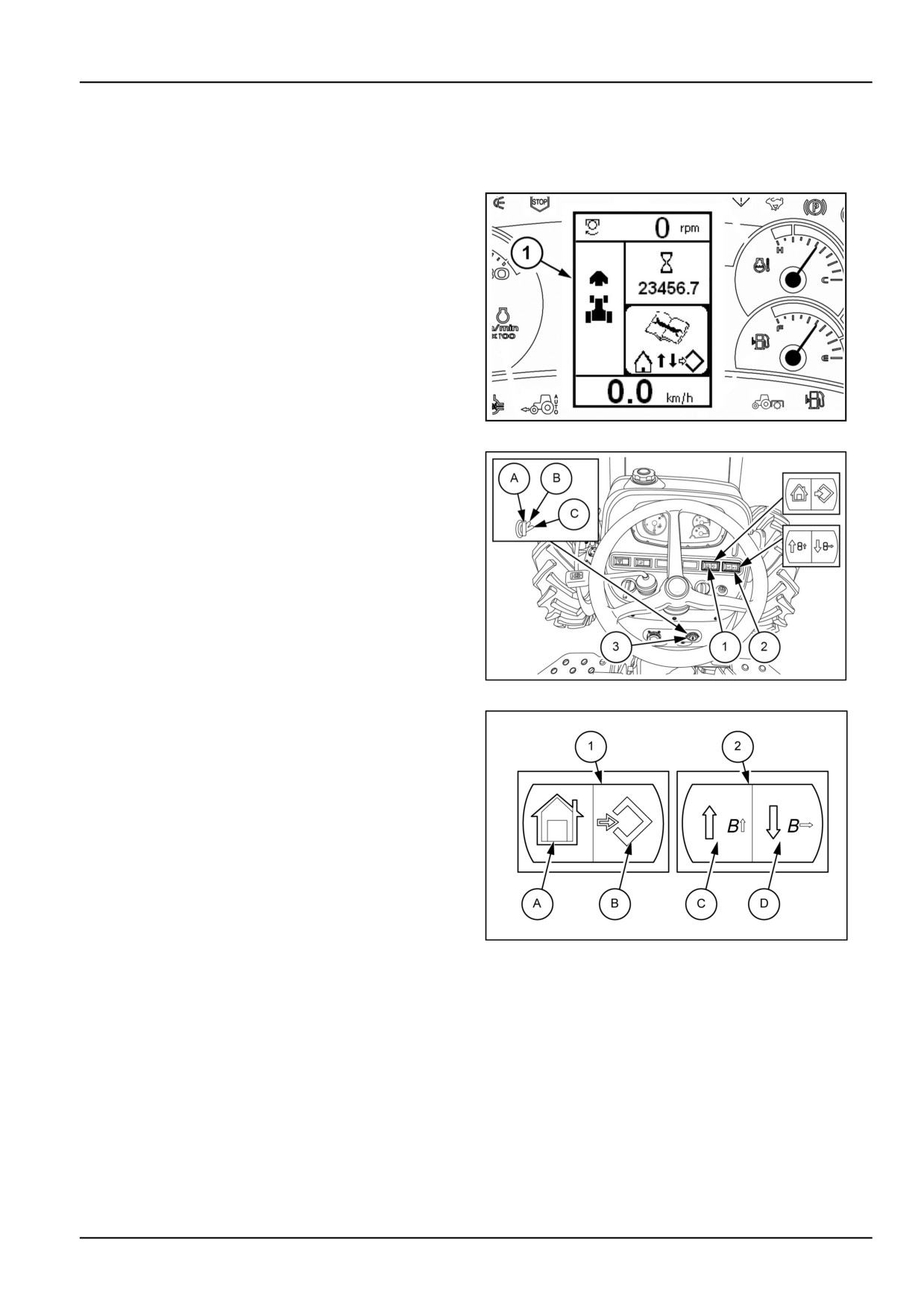
The multifunction Liquid Crystal Display (LCD) (1) can
show useful and necessary information when driving and
a menu for making the following adjustments:
• Tractor speed calibration .
• Implement width.
• Programmed maintenance.
• Sound level on/off on pressing the buttons.
• Diesel particulate filter control (DPF).
• Resetting oil change.
• Viewing active error codes and warning messages.
DCAPLT5NE044S3A
1
Navigate the menu with the rocker switches (1) and (2) ..
Each rocker switch provides two controls, depending on
the position where the rocker switch is pressed.
To enter the “SETUP MENU”, turn the start switch key
(3)to position (B), panel powered, and subsequently keep
the switch (1) pressed on the symbol (B) for more than
three seconds.
GNIL14TR00516AA
2
Switch (1)
(A) Exit/Cancel. Use this switch position to cancel or quit
the setting and programming modes.
(B) Menu/Enter. Use this switch position to enter the
menu or confirm the settings.
Switch (2)
(C) Up arrow = scrolling up through the menu or numer-
ical value. Press this switch position repeatedly to scroll
forwards in the menu or change the value of a number.
MOIL12TRO0042AB
3
(D) Down arrow = scrolling down through the menu or nu-
merical value. Press this switch position to scroll back-
wards in the menu or to move to the right of a position.
3-21
3 - CONTROLS AND INSTRUMENTS
Adjusting the dashboard/display brightness
NOTE: During this adjustment bear in mind that the illumination will always be greater with the marker lights off,
whereas with the marker lights on there will automatically be a decrease in the brightness of the display.
GNIL14TR00585FA
1
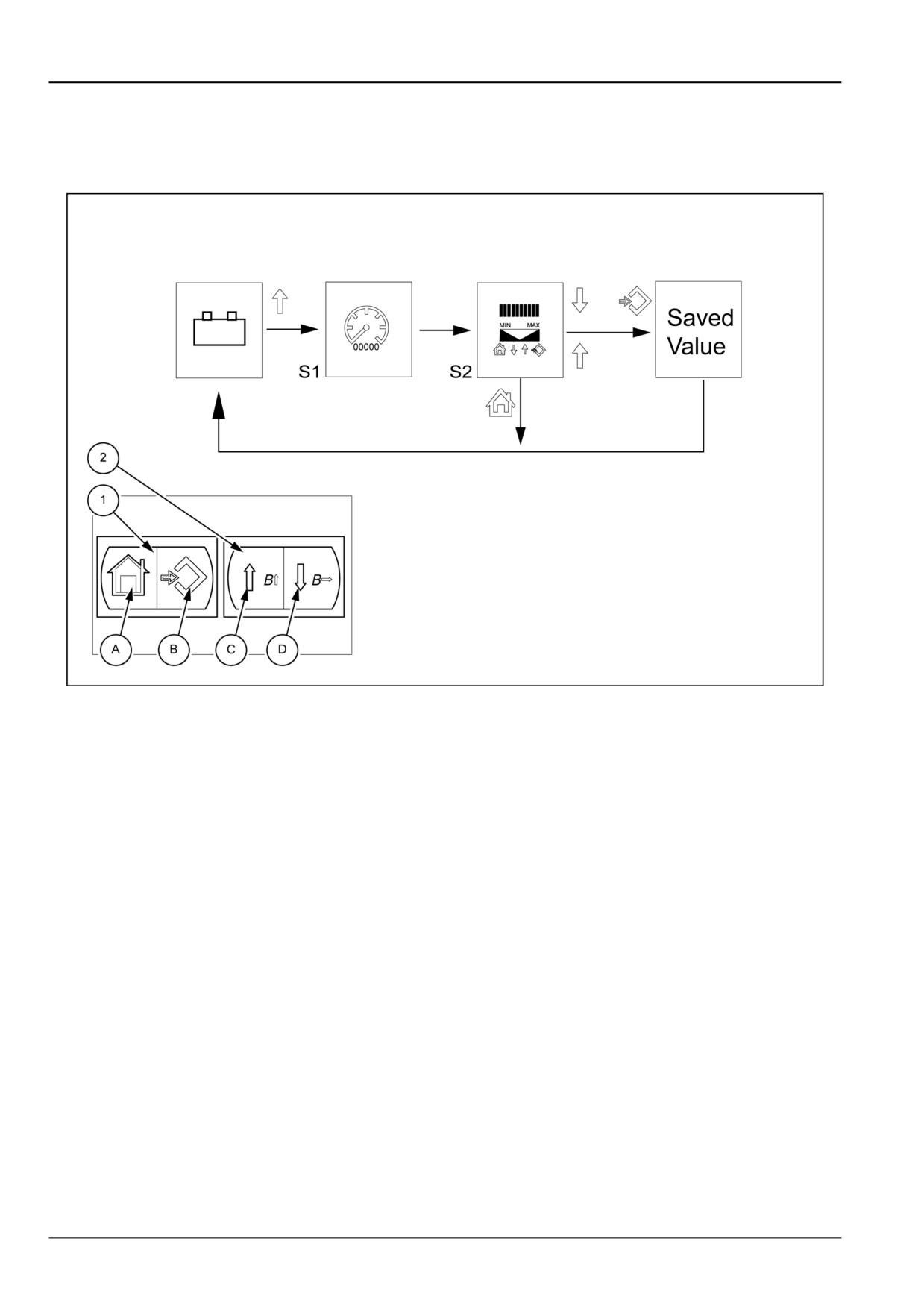
Brightness of warning lights and indicator pointers
1. With the panel powered, press and hold down the
5. Press the switch (1) on the symbol (B) to save the
switch (2) on the up arrow (C) for 3 seconds
setting.
2. The central display will show the detail (S1).
6. Two seconds after saving you are automatically re-
turned to the initial condition.
3. Release the direction key to pass on to the next screen
(S2).
7. Press the switch (2) on the symbol (D) again to exit
the programming menu.
4. Press switch (2) on symbol (C) to increase or on sym-
bol (D) to decrease the brightness of the warning lights
and hands of the indicators, to set the required bright-
ness.
NOTE: If you want to stop the adjustment without saving, press the switch (1) on the symbol (A) to exit the adjustment.
3-22
3 - CONTROLS AND INSTRUMENTS
GNIL14TR00584FA
2
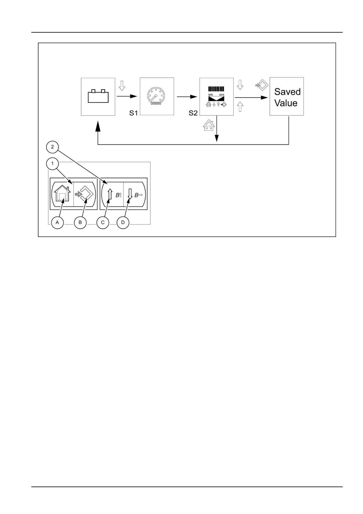
Central display brightness
1. With the panel powered, press and hold down the
5. Press the switch (1) on the symbol (B) to save the
switch (2) on the up arrow (D) for 3 seconds.
setting.
2. The central display will show the detail (S1).
6. Two seconds after saving you are automatically re-
turned to the initial condition.
3. Release the direction key to pass on to the next screen
(S2).
7. Press the switch (2) on the symbol (D) again to exit
the programming menu.
4. Press the switch (2) on the symbol (C) to increase or
on the symbol (D) to decrease the brightness of the
central display until you reach the desired brightness.
NOTE: If you want to stop the adjustment without saving, press the switch (1) on the symbol (A) to exit the adjustment.
3-23
3 - CONTROLS AND INSTRUMENTS
Activating/deactivating buzzer
MOIL12TRO0050FB
1
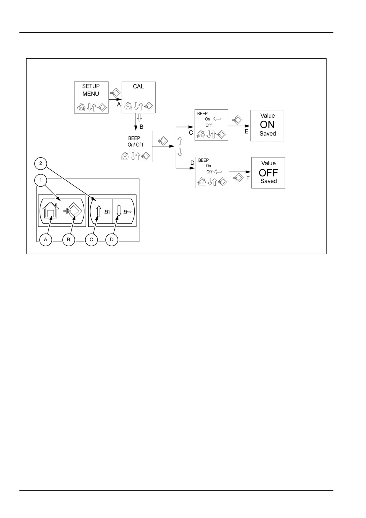
If you want to turn on or off the audible warning signal
OFF”. Press the switch (2) on the symbol (D) or (C) to
that sounds each time a button is pressed, proceed as
change the setting.
follows:
4.
”ON” = warning signal ”BEEP“ ON
1. Press the switch (1) on the symbol (B) for longer than
5.
”OFF” = warning signal ”BEEP“ OFF
three seconds to enter the programming menu
The central display shows the words “SETUP MENU”.
6. After selecting the desired condition ( ON or OFF),
Release the switch.
press the switch (1) on the symbol (B) to confirm. The
display will show “Value ON Saved” when enabling the
2. Press the switch (2) on the symbol (D) a number
audible warning signal. The display will show “Value
of consecutive times until the display shows ”BEEP
OFF Saved” when disabling the audible warning sig-
ON/OFF”.
nal.
3. Press the switch (1) on the symbol (B). The display
will show the last setting made, ”BEEP ON” or ”BEEP
NOTE: If you want to stop the display, press the switch (1) on the symbol (A). This will automatically return you to the
initial page display ”BEEP ON/OFF”. Press the same symbol again to exit the programming menu.
3-24
3 - CONTROLS AND INSTRUMENTS
Programming maintenance work
MOIL12TRO0048FD
1
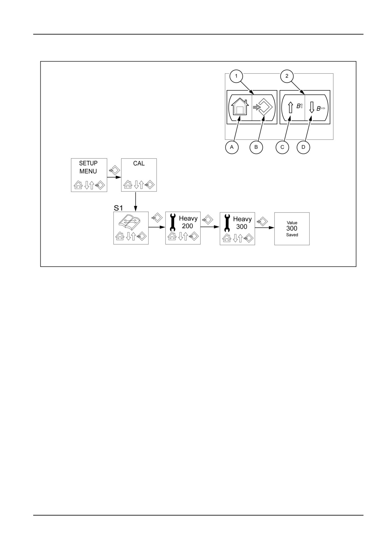
Setting a maintenance reminder for heavy-duty use
This function allows the operator to program maintenance
4. Press the switch (1) on the symbol (B) to change the
according to two levels of importance: “routine (LIGHT)”
setting of the first flashing digit. (In the above example,
or “heavy-duty use (HEAVY)”. Proceed as follows:
the number “2”).
1. Press the switch (1) on the symbol (B) for more than
5. Press the switch (2) on the symbol (C) to increase the
three seconds to enter the programming menu
value. Press the same switch on the symbol (D) to
The display will show “SETUP MENU”. Release the
move to the next digit.
switch.
6. If you do not want to save the new setting and go back
2. Press the switch (2) on the symbol (D) a number of
to the start of programming, press the switch (1) on the
times until the display shows the symbol for program-
symbol (A).
ming maintenance intervals (S1).
7. To save the new maintenance schedule, press the
3. Press the switch (1) on the symbol (B). The display
switch (1) on the symbol (B). The display will show
will show the “Heavy” screen with the hours that re-
confirmation that the new value has been saved.
main until maintenance is due. The setting cannot be
8. After two seconds, you will exit the programming
changed at this stage.
menu for maintenance operations.
NOTE: As the time for the programmed work approaches, the display will show a warning in the number of operating
hours that remain until maintenance is due. At the end of the countdown, the display will show “Heavy “ followed by an
alarm message to indicate that the time has expired. At the end of the count, in the maintenance work programming
menu, the counter will show three dashes and must be re-programmed as described above.
3-25
3 - CONTROLS AND INSTRUMENTS
MOIL12TRO0049FD
2
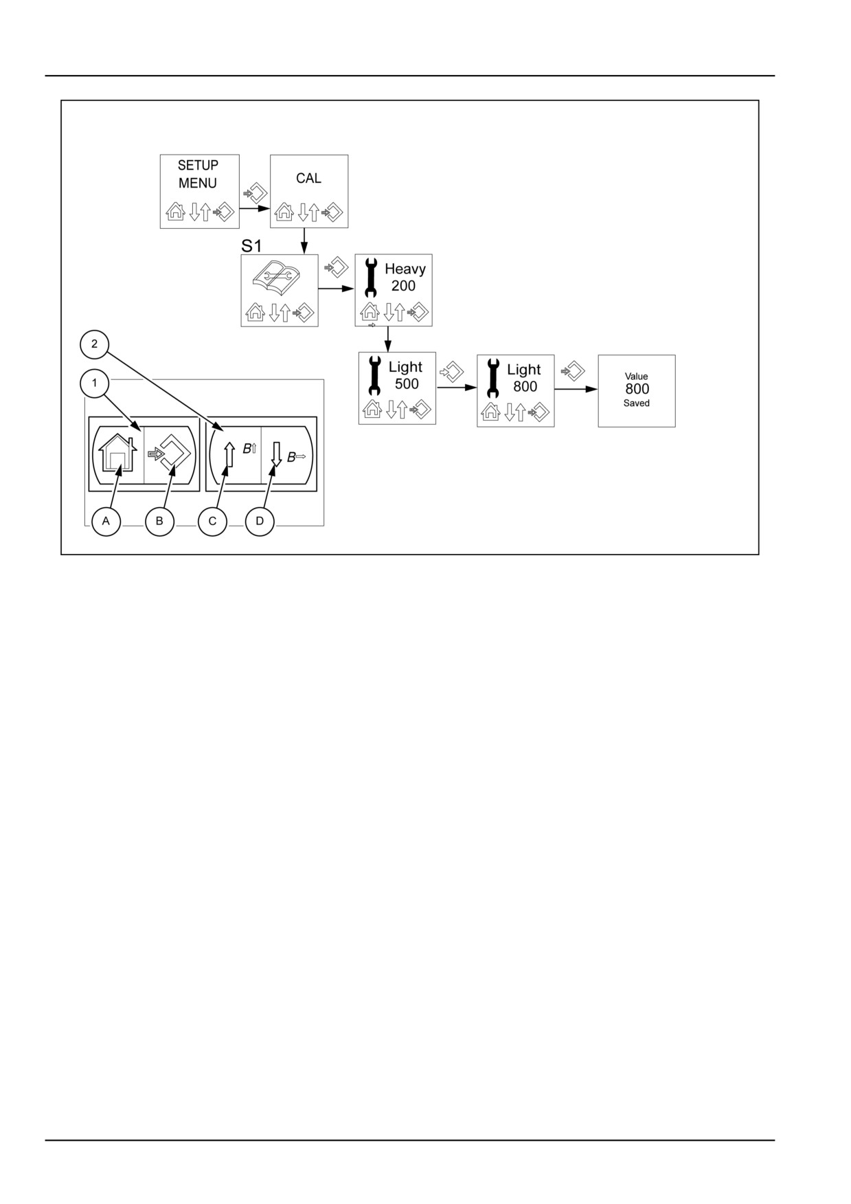
Setting a maintenance reminder for light use
Setting a reminder for routine maintenance
1. Press the switch (1) on the symbol (B) for longer
6. Press the switch (2) on the symbol (C) to increase
than three seconds to enter the programming menu.
the value. Press the symbol (D) to move to the next
Release the switch.
digit.
2. Press the switch (2) on the symbol (D) a number of
7. If you do not want to save the new setting and go
times until the display shows the symbol for program-
back to the start of programming, repeatedly press
ming maintenance intervals (S1).
the switch (1) on the side with the symbol (A).
3. Press the switch (1) on the symbol (B). The display
8. To store the new maintenance program, press the
will show the “Heavy” screen with the hours that re-
switch (1) on the symbol (B). The display will show
main until maintenance is due.
confirmation that the new value has been saved.
4. Press the switch (2) on the symbol (D). The display
9. After two seconds, you will exit the programming
will show the “Light” screen with the hours that re-
menu for maintenance operations.
main until maintenance is due. The setting cannot
be changed at this stage.
5. Press the switch (1) on the symbol (B) to change
the setting of the first flashing digit.
(In the above
example, the number “5”).
NOTE: As the time for the programmed work approaches, the display will show a warning in the number of operating
hours that remain until maintenance is due. At the end of the countdown, the display will show “Light “ followed by an
alarm message to indicate that the time has expired. At the end of the count, in the maintenance work programming
menu, the counter will show three dashes and must be re-programmed as described above.
3-26
3 - CONTROLS AND INSTRUMENTS
Resetting the oil change counter
MOIL12TRO0054FC
1
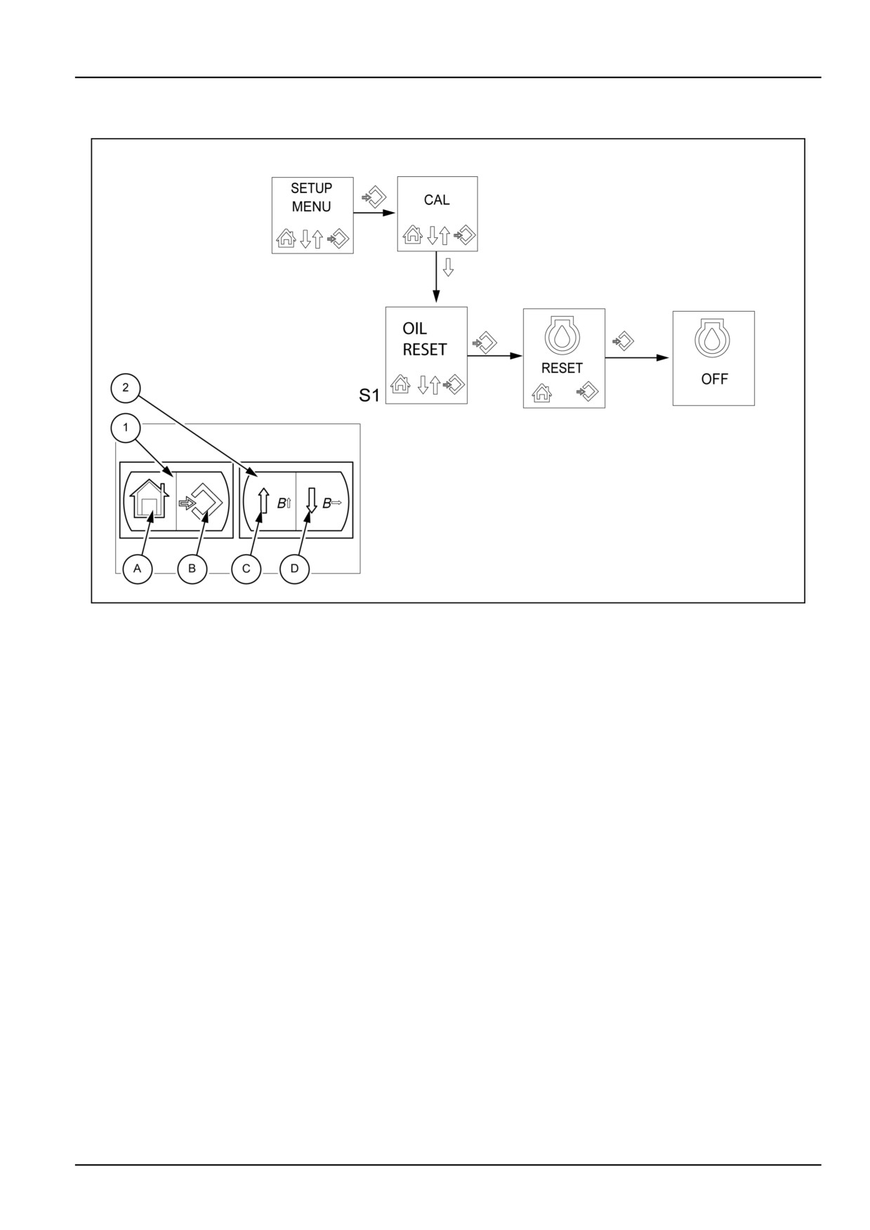
NOTE: For this procedure the engine must be switched off. At every oil change you must reset the operating hours
counter for the engine oil, as described below:
1. Press the switch (1) on the symbol (B) for longer than
4. Press the switch (1) on the symbol (B) to reset the
three seconds to enter the programming menu
hourmeter. The display will show “OFF”.
The display will show the words “SETUP MENU”. Re-
5. After two seconds, the display automatically returns
lease the switch.
to the initial display. Now press the switch (1) on the
2. Press the switch (2) on the symbol (D) a number of
symbol (A) to exit the programming menu.
consecutive times until the display shows “OIL RE-
SET” S1.
3. Press the switch (1) on the symbol (B) to show “RE-
SET” on the display.
NOTE: If you reset the hourmeter correctly, the pressure indicator for the engine oil on the instrument cluster will flash
for two seconds.
3-27
3 - CONTROLS AND INSTRUMENTS
Viewing error codes
MOIL12TRO0055FC
1
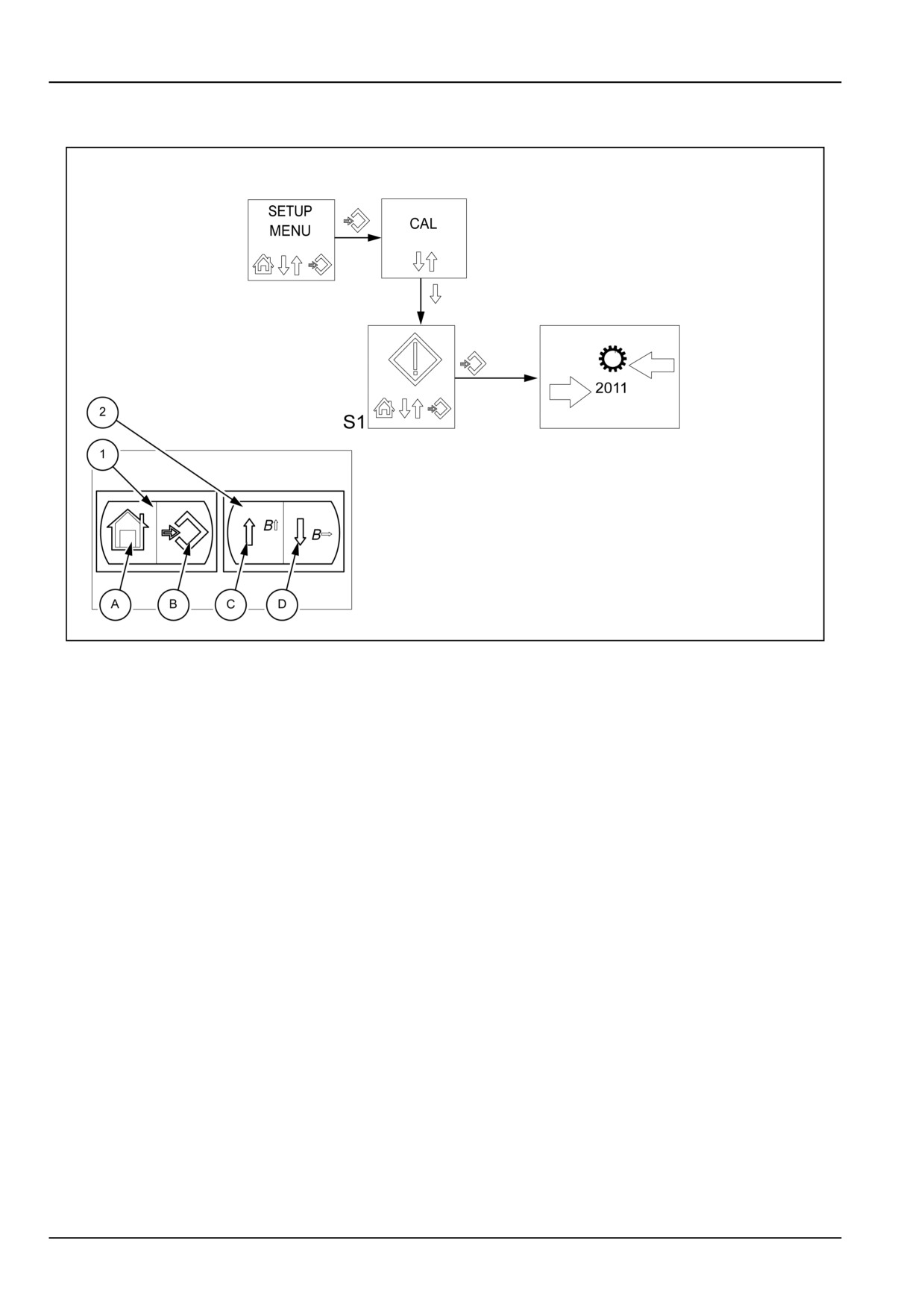
f it is necessary to know the list of error codes or
1. The symbol of the failed component appears on the
warnings that are stored by the control unit and that are
display together with its error code. Stop the work.
not permanently visible, proceed as described below:
Contact the authorized dealer. The error codes or
warnings are displayed in two different ways:
1. Press the switch (1) on the symbol (B) for longer than
three seconds to enter the programming menu
2. The display will show only the symbol with no error
The central display shows the words “SETUP MENU”.
code. When only the symbol is displayed, this is a
Release the switch.
warning. The warning symbols indicate conditions.
Although these conditions do not compromise the op-
2. Press the switch (2) on the symbol (D) a number of
eration of the tractor, these warning symbols should
consecutive times until the display shows the symbol
not be ignored. Take appropriate action where neces-
for the error codes (S1).
sary.
3. Press the switch (1) on the symbol (B) to display the
3. Press the switch (1) on the symbol (A) to exit the error
error codes in the memory.
codes display.
The error codes or warnings are displayed in two
different ways:
NOTE: The current error codes are displayed in sequence. Each code is displayed three times blinking for four sec-
onds.
3-28
4 - OPERATING INSTRUCTIONS
4 - OPERATING INSTRUCTIONS###_4_###
STARTING THE UNIT
Starting the tractor
DANGER
Run-over hazard!
Start engine only from operator’s seat. If you
bypass the safety start switch, the engine can
start with the transmission in gear and the ma-
chine will move. DO NOT short or connect
across terminals of the starter solenoid.
Failure to comply will result in death or seri-
ous injury.
D0102A
To start the engine:
1. Step onto the tractor from left-hand side only.
2. Sit on the operator’s seat and fasten seat belt.
3. Make sure that both gear-shift levers and shuttle lever
are in neutral.
NOTICE: Neutral start switch prevents operation of the
starting motor unless the gear levers are in the neutral
position.
4. Make sure the Power Take-Off (PTO) is disengaged.
5. Depress the clutch pedal.
NOTICE: Clutch switch prevents operation of the start-
ing motor unless the clutch pedal is depressed.
6. Turn the key switch to the start position. Release the
key when the engine starts.
NOTICE: Never push or tow the tractor to start the engine.
Doing so may overstress the drive train.
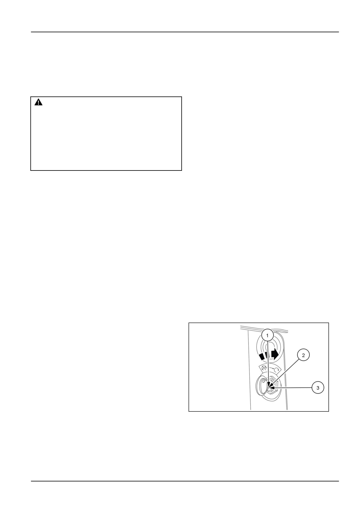
A three-position key-start switch is installed. The key-start
switch positions are as follows:
Position 1
Electrical equipment Off.
Position 2
Accessories on (head
lamp, Instrument cluster,
horn and gauges, brake
lights, turn signals) engine
'ON'.
Position 3
Engine Start -- The full
clockwise position activates
the starter motor, to start
the engine. Once the key
is released, the switch
GNIL14TR00558AA
1
returns to Position 2.
4-1
4 - OPERATING INSTRUCTIONS
Starting a cold engine
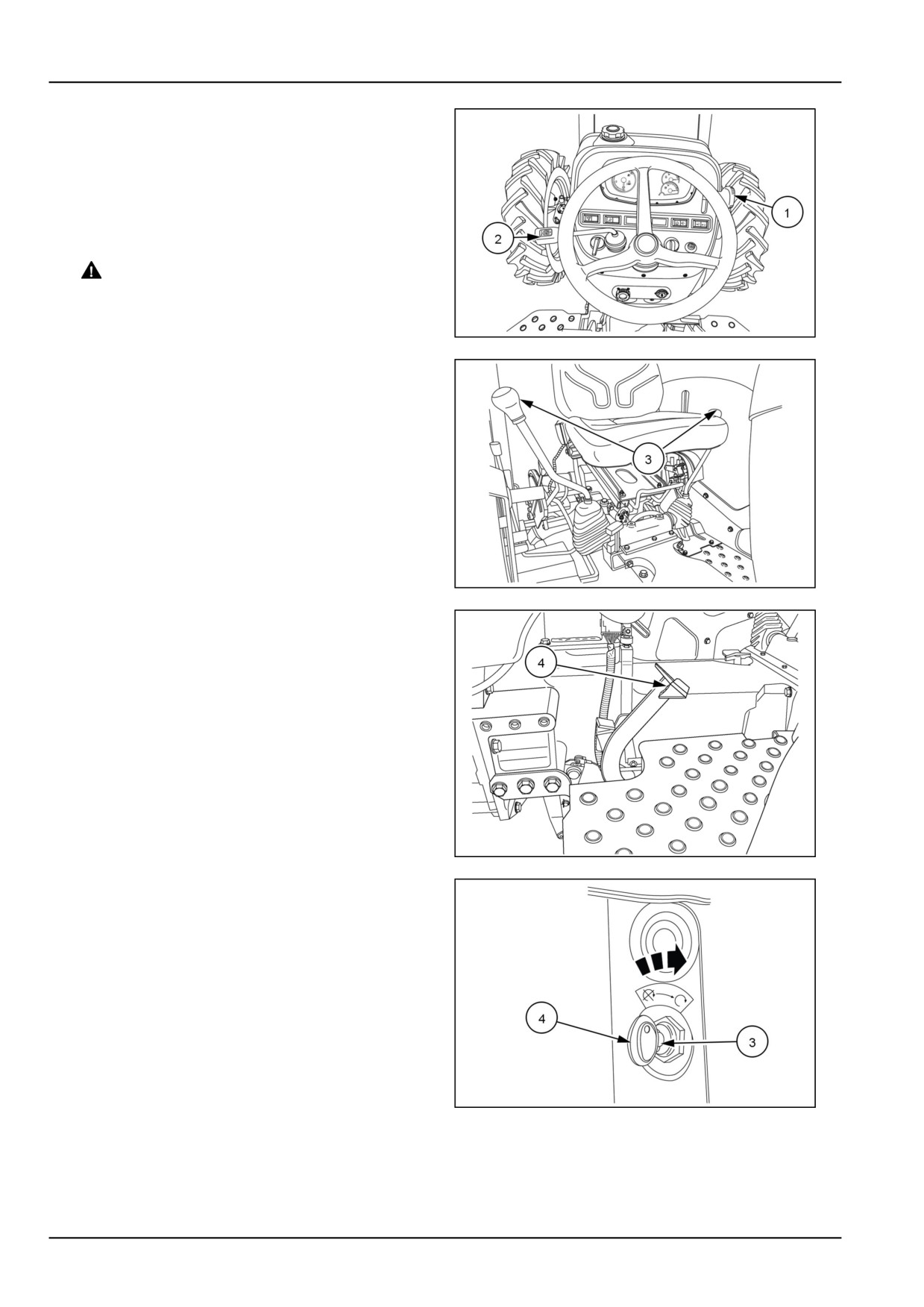
1. Place the hand throttle lever (1) in the halfway position.
2. Place transmission shuttle shift lever (2) in the neutral
position.
3. Place both gear levers (3) in the neutral position.
4. Depress the clutch pedal (4).
5.
WARNING
Explosion hazard!
DO NOT use ether starting fluid. Serious en-
gine damage, explosion, death, or serious per-
GNIL14TR00512AA
2
sonal injury could occur.
Failure to comply could result in death or seri-
ous injury.
W0148A
Turn the key switch (4) fully clockwise to the “START”
(3) position to operate the starting motor. Rotate the
engine but do not operate the starter motor for more
than 10 s.
6. After the engine starts, allow the key switch to return
to the “RUN” position.
7. Return the hand throttle lever to the idle position and
check that all warning lights are off and gauge read-
ings are normal.
GNIL14TR00785AA
3
86090118
4
GNIL14TR00558AA
5
4-2
4 - OPERATING INSTRUCTIONS
Starting a cold engine in cold weather
Your tractor has a diesel engine. Before starting a cold
engine, the precombustion chambers of the engine must
be heated with electrical glow plug heating elements. .
1.
WARNING
Explosion hazard!
DO NOT use ether starting fluid. Serious en-
gine damage, explosion, death, or serious per-
sonal injury could occur.
Failure to comply could result in death or seri-
ous injury.
W0148A
GNIL14TR00558AA
6
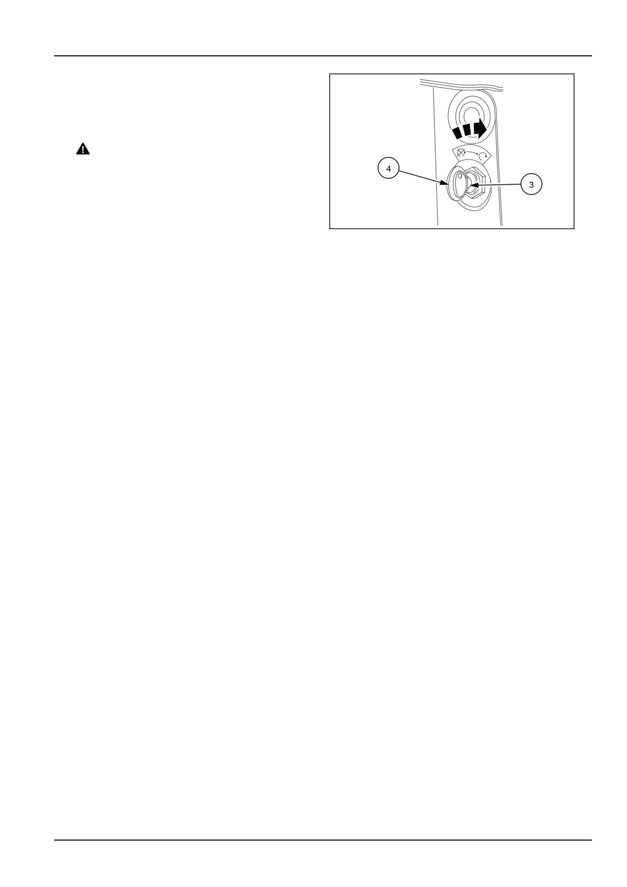
Turn the keyswitch (4) fully clockwise to the “START”
(3) position to operate the starting motor. Do not op-
erate the starter motor for more than 10 seconds.
NOTICE: When starting the machine after long periods,
avoid immediate use of hydraulics. It is necessary to al-
low time for enough lubrication of all moving parts before
subjecting them to work loads, particularly if outdoor tem-
peratures approach 0°C (32°F ). Run the engine at 1300
- 1500 RPM for about 15 min to bring the rear drive oil up
to normal operating temperature.
NOTE: A coolant immersion heater is available as a
dealer installed option. This heater allows for easier
starting in temperatures below -17.7 °C (0 °F) by warming
the engine coolant.
4-3
4 - OPERATING INSTRUCTIONS
Starting in warm weather or when the engine
is hot
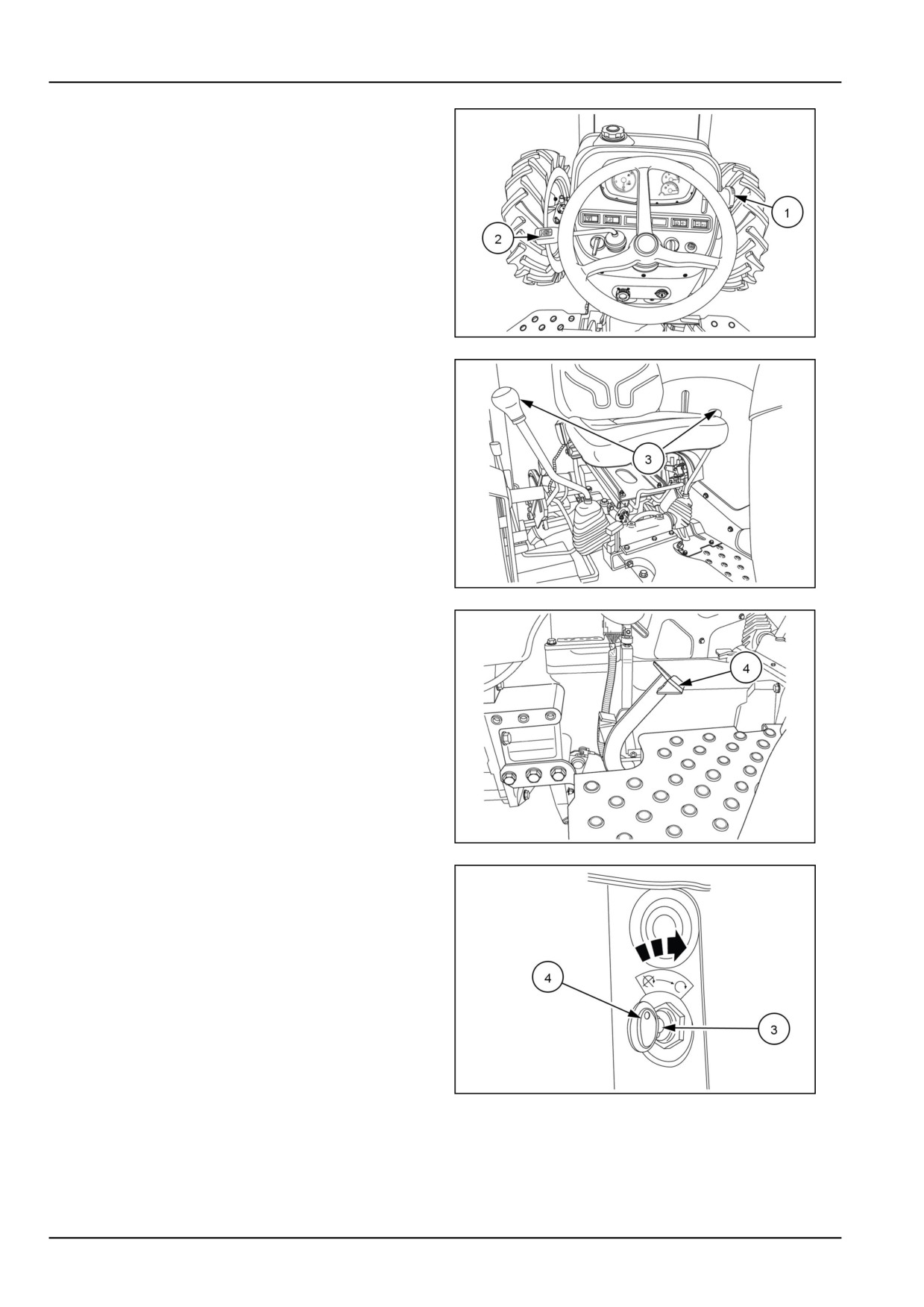
1. Place the hand throttle lever (1) in the halfway position.
2. Place transmission shuttle shift lever (2) in the neutral
position.
3. Place both gear levers (3) in the neutral position
4. Depress the clutch pedal (4).
5. Turn the key- switch (4) fully clockwise to the “START”
(3) position to operate the starting motor. Do not op-
erate the starter motor for more than 10 s
GNIL14TR00512AA
7
6. After the engine starts, allow the key to return to the
“RUN” position.
7. Return the hand throttle lever to the idle position and
check that all warning lights are off and gauge read-
ings are normal.
GNIL14TR00785AA
8
86090118N
9
GNIL14TR00558AA
10
4-4

4 - OPERATING INSTRUCTIONS
OPERATOR ALERT LOGIC TABLE
Alarm
Ignition key
Parking brake
SEAT IN or
Power Take-
Hi-Low range
Logic control
OUT
Off (PTO)
lever
clutch
Yes
OFF
Change of
Either
Either
Either
Electronic
state
module
Yes
ON
Not engaged
OUT
Either
Either
Electronic
module
Yes
ON
Engaged
OUT
Engaged
Either
Electronic
module
Yes and
ON (Engine
Not engaged
Operator gets
Either
Engaged (High
Electronic
shutdown
running)
out of the seat
or low)
module,
harness logic
and Engine
Control Unit
(ECU)
Yes and
ON (Engine
Engaged
OUT
Not engaged
Engaged (High
Electronic
shutdown
running)
or low)
module,
harness logic
and Engine
Control Unit
(ECU)
Either (seat IN or OUT) = Operator may or may not be on the seat
Either (Hi-Low range lever) = High-Low lever engaged or disengaged
Either (PTO clutch) = PTO engaged or disengaged
Change of state = Engage to disengage
4-5
4 - OPERATING INSTRUCTIONS
STOPPING THE UNIT
Shut off the engine
To shut off the engine, carry out the following procedure
1. Remain in the operator’s seat.
2. Bring the tractor to a complete stop.
3. Bring the hand throttle lever to the idle position.
4. Apply the park brake.
5. Place both gear shift levers and the shuttle shift lever
are in neutral position.
6. Place the PTO clutch lever in the disengaged position.
7.
WARNING
Crushing hazard!
GNIL14TR00559AA
1
ALWAYS make sure the work area is clear of
bystanders and domestic animals before rais-
ing or lowering the equipment.
Failure to comply could result in death or seri-
ous injury.
W0123A
Move the hydraulic lift position control lever fully for-
ward to lower all hydraulic equipment to the ground.
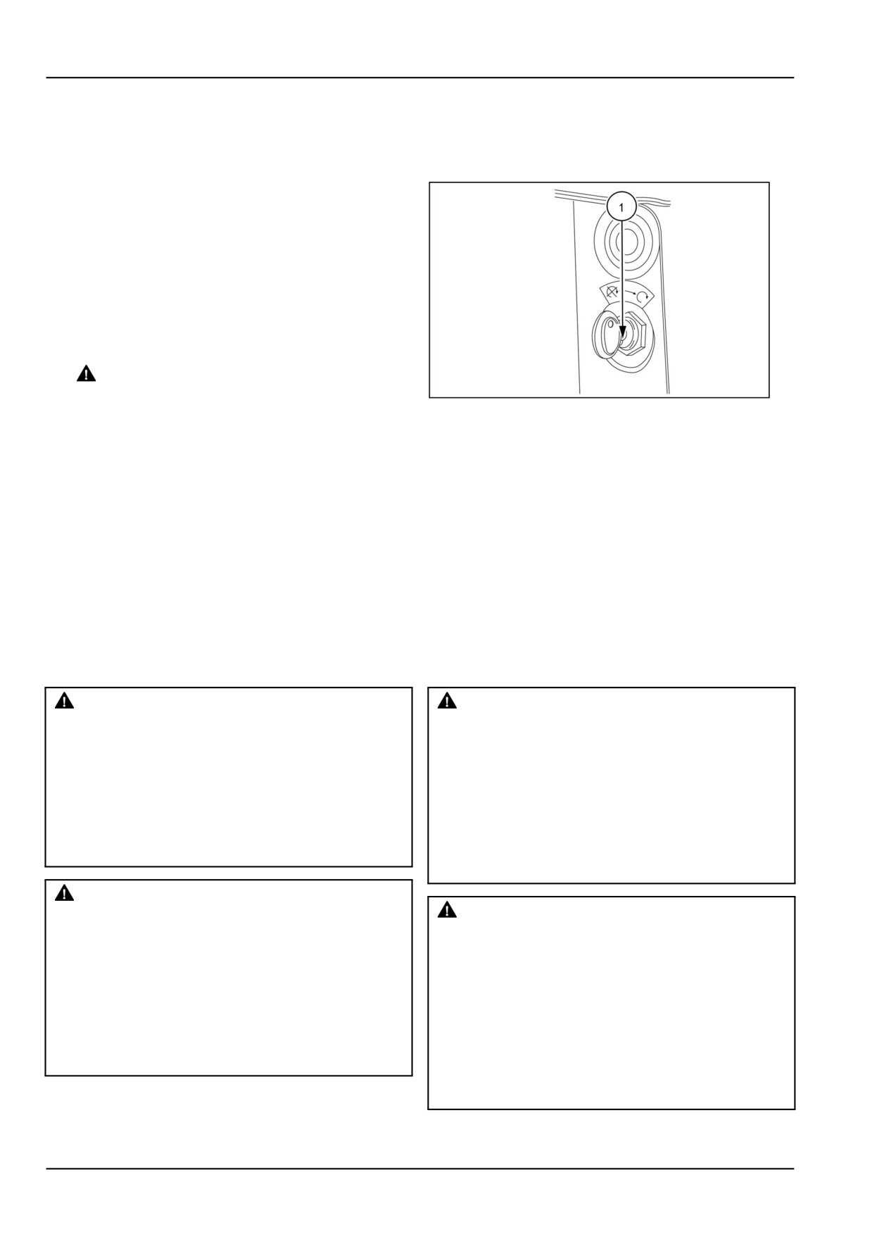
8. Place the key switch (1) into the “STOP” position.
MOVING THE UNIT
Roll Over Protective Structure (ROPS) frame - Basic instructions
WARNING
WARNING
Misuse hazard!
Roll-over hazard!
Your machine is equipped with an operator
A folded Roll-Over Protective Structure
protective structure. DO NOT weld, drill holes,
(ROPS) does not provide roll-over protection.
attempt to straighten, or repair the protective
Do not operate the machine with the ROPS
structure. Modification in any way can reduce
folded as a standard operating mode. Raise
the structural integrity of the structure.
the ROPS immediately after low clearance
Failure to comply could result in death or se-
use or transport.
rious injury.
Failure to comply could result in death or se-
W0001B
rious injury.
W0938A
WARNING
WARNING
Crushing hazard!
Always wear the seat belt when operating the
Roll-over hazard!
machine with the Roll Over Protective Struc-
Always pull from the drawbar. DO NOT attach
ture (ROPS) in the upright position. If the
chains or ropes to the Roll Over Protective
ROPS is in the folded position, the seat belt
Structure (ROPS) for pulling purposes, as the
should not be used. Raise the ROPS and wear
machine could tip over. When driving through
the seat belt as soon as conditions allow.
door openings or under low overhead objects,
Failure to comply could result in death or se-
make sure there is sufficient clearance for the
rious injury.
ROPS.
W0462A
Failure to comply could result in death or se-
rious injury.
W0463A
4-6
4 - OPERATING INSTRUCTIONS
DANGER
DANGER
Crushing hazard!
Roll-over hazard!
DO NOT operate the machine with the
A folded Roll-Over Protective Structure
Roll-Over Protective Structure
(ROPS) re-
(ROPS) does not provide roll-over protection.
moved. Remove the ROPS only for service or
Do not operate the machine with the ROPS
replacement.
folded as a standard operating mode. Raise
Failure to comply will result in death or seri-
the ROPS immediately after low clearance
ous injury.
use or transport.
D0032A
Failure to comply will result in death or seri-
ous injury.
D0058A
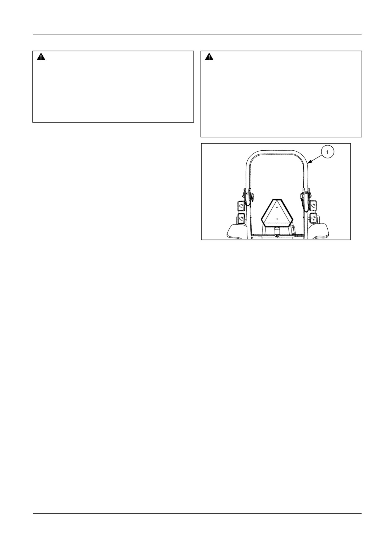
Roll Over Protective Structure (ROPS)
A foldable Roll Over Protective Structure (ROPS) (1), and
seat belts are standard equipment on this tractor at the
time of factory assembly. Operate with this ROPS in the
“up” position whenever possible. Use the ROPS in the
“folded” position only when absolutely necessary. If the
ROPS was deleted by the original purchaser or has been
removed, it is recommended that you equip your tractor
with a ROPS and seat belts.
76099309N
1
4-7
4 - OPERATING INSTRUCTIONS
Roll Over Protective Structure (ROPS) Fold-
ing Procedure
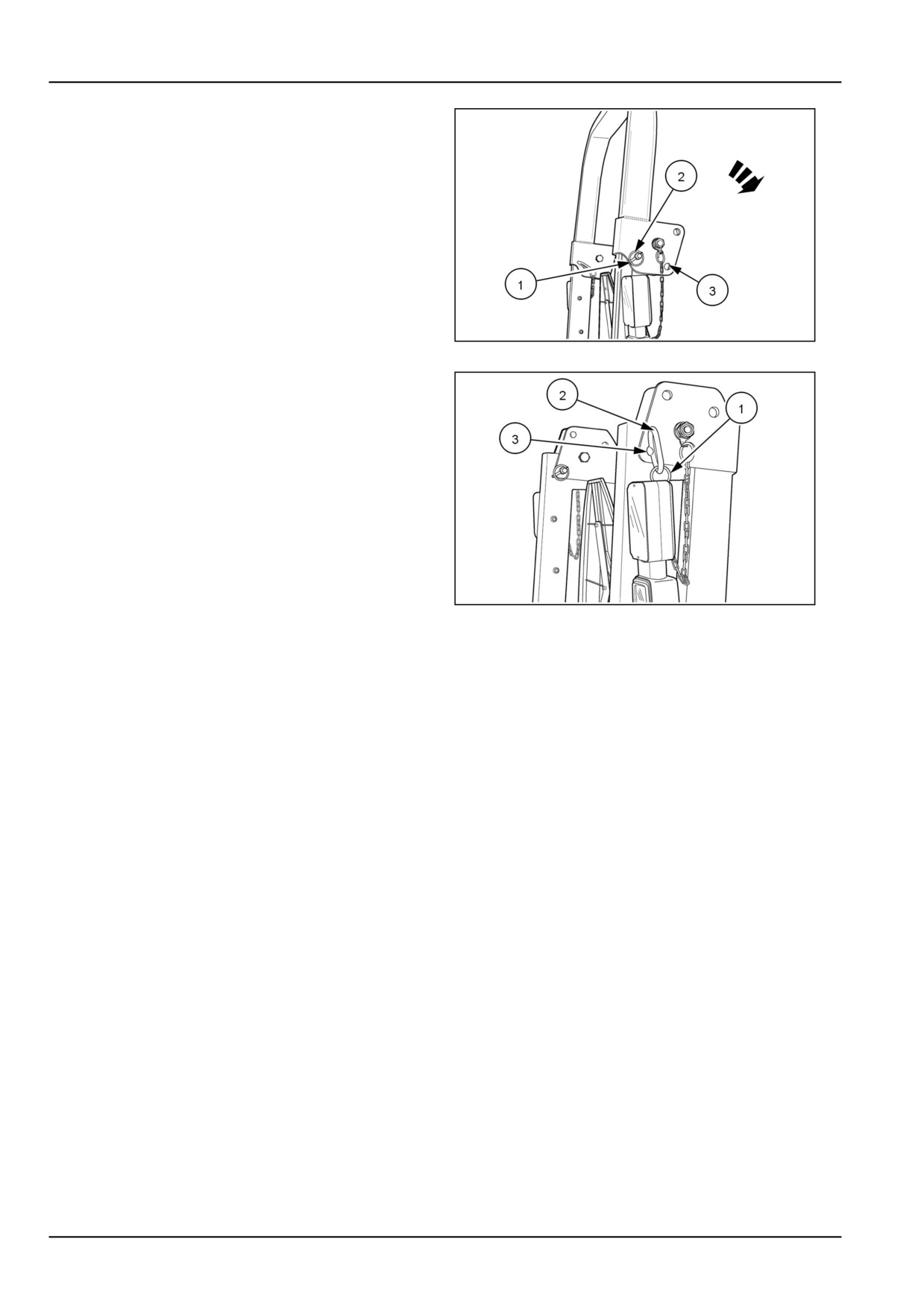
To fold the ROPS into the “DOWN” position, remove re-
taining ring (1), from the pin (2). Remove pin from the
latching bracket, on both sides of the ROPS.
86065629N
2
Rotate top part of ROPS fully downward until brackets
contact ROPS uprights. Reinstall pin (2)into lower retain-
ing hole (3). Re-attach the retaining ring (1).
86065630N
3
4-8
5 - TRANSPORT OPERATIONS
5 - TRANSPORT OPERATIONS###_5_###
ROAD TRANSPORT
Towing attachments
WARNING
Overturning hazard!
Always use the drawbar, pick-up hitch,
or lower links in the lowered position for
pull-type work. Do not pull from the lower
links if they are above the horizontal position.
Failure to comply could result in death or se-
rious injury.
W0417A
Swinging/Extendable drawbar
Use the drawbar to tow agricultural implements and trail-
ers.
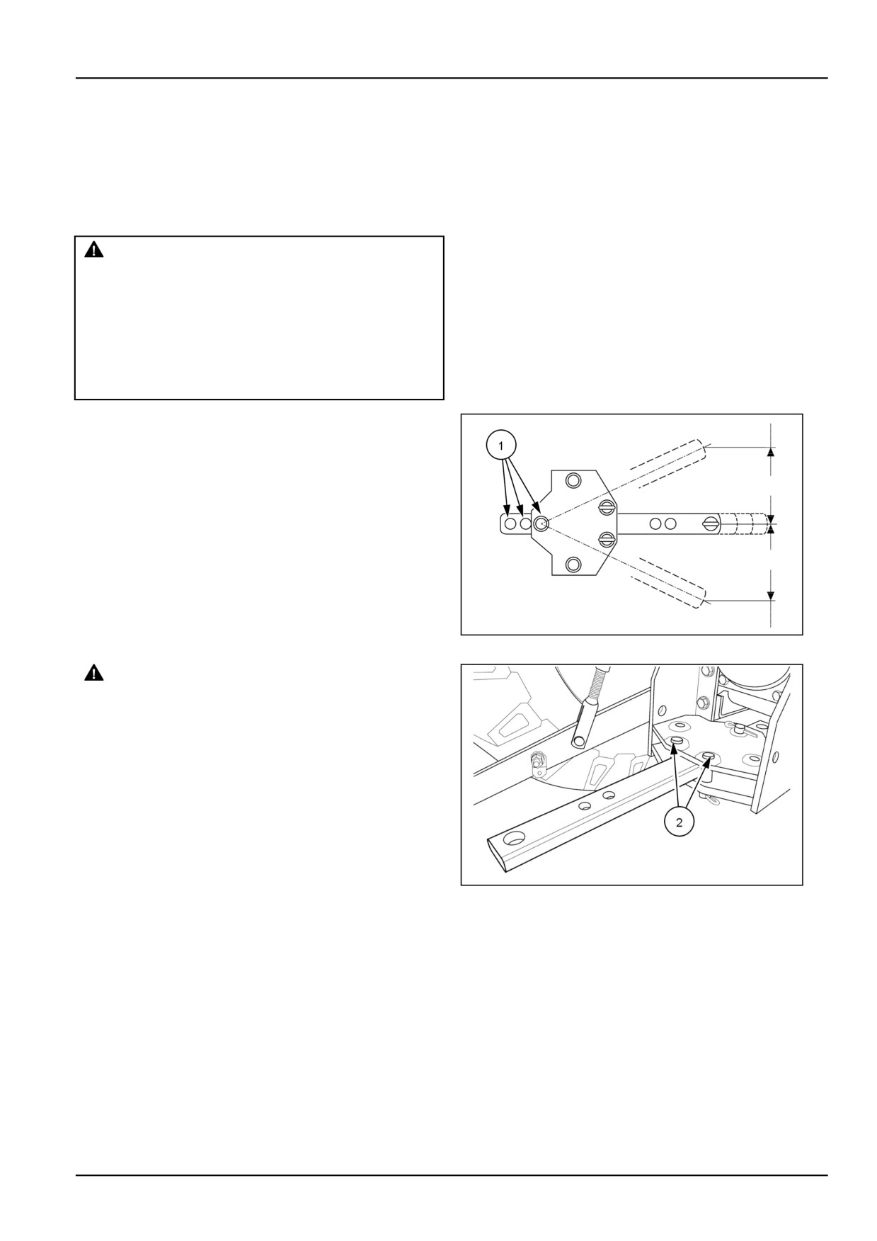
The drawbar length may be adjusted by inserting the pin
in the series of holes (1) in the drawbar.
NOTICE: When transporting equipment on roads, a safety
chain with a tensile strength equal to the gross weight of
the implement should be installed between the tractor and
implement hitch.
76099306N
1
WARNING
Collision hazard!
During road transport, the drawbar must be
locked in the center position, and the imple-
ment must be centered behind the tractor.
Failure to comply could result in death or se-
rious injury.
W0324A
Drawbar swing may be adjusted by location of pins (2).
76099307N
2
5-1
5 - TRANSPORT OPERATIONS
Telescoping stabilizers and flex end links
WARNING
Machine damage can cause accidents!
Only operate three-point equipment with both
flex ends returned to the latched position.
Failure to comply could result in death or se-
rious injury.
W0467A
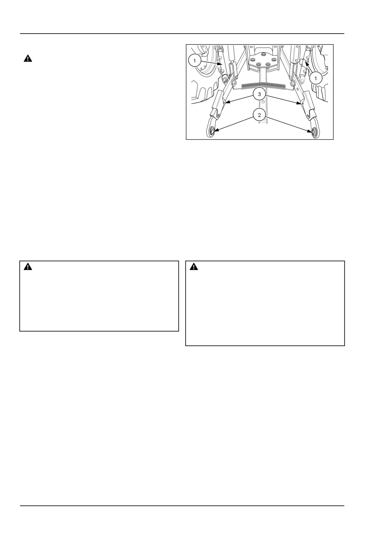
Telescoping stabilizers and lower lift arms with flex ends
are a standard equipment, for the tractor.
The telescoping stabilizers (1) use a pin and multiple hole
arrangement for easy adjustment, for side to side move-
76080380N
3
ment of the three-point linkage.
The flex ends (2) on the lower lift arms are adjusted by
pushing down on the clamp (3) and sliding the ends to the
desired length. Once the implement is attached, push in
on the flex ends until the ends are in the latched position
in the arms,
NOTICE: Cycle the three point linkage through the entire
travel and check for interference with the rear tires. If
interference is present, adjust stabilizers as needed.
RECOVERY TRANSPORT
Towing the tractor
WARNING
WARNING
Loss of control hazard!
Hazard to bystanders!
Do not tow the machine faster than 8 kph (5
Do not use cables or rope to tow the machine.
mph). The steering is much slower and steer-
If the cable or rope breaks or slips, it may whip
ing wheel effort is much greater without the
back with enough force to cause serious in-
engine running.
jury. When using a chain, attach the chain with
Failure to comply could result in death or se-
the hook's open side facing UP. If the hook
rious injury.
slips, it will drop down instead of flying up.
W0076A
Failure to comply could result in death or se-
rious injury.
W0441A
NOTICE: The tractor should only be towed a short dis-
tance, such as out of a building. Do not tow on roadways
or as a method of transport.
If towing the tractor obey the following instructions
1. Use a strong chain when towing the tractor
2. Tow the tractor from the rear using only the drawbar,
rear tow hitch, or the three-point hitch.
3. Tow the tractor from the front using the tow pin in the
front weights or front support. Have an operator steer
and brake the tractor.
4. If possible, run the engine to provide lubrication, to
avoid damaging the transmission or other components
that turn, but that are not lubricated during towing,
such as the transmission and power steering.
5-2
5 - TRANSPORT OPERATIONS
Carrying the tractor on a transporter
Transport the tractor will all four wheels on a flat bed trailer
or truck. Securely chain the tractor to the transporter.
Use drawbar hanger for a rear tie down point.
NOTICE: Do not place chain around the steering cylin-
ders, or other components that could be damaged by con-
tacting the chain or by heavy loading.
5-3
6 - WORKING OPERATIONS
6 - WORKING OPERATIONS###_6_###
GENERAL INFORMATION
Field operation
Before operating
Running-in procedure
WARNING
Your tractor will provide long and dependable service if
IMPROPER OPERATION OF THIS MACHINE
given proper care during the first 50 h running-in period
CAN CAUSE DEATH OR SERIOUS INJURY.
and if serviced at the recommended intervals.
MAKE SURE THAT EVERY OPERATOR:
Avoid overloading the engine. Operating in a high gear
-learns and practices the safe use of machine
controls in a safe, clear area before operating
under heavy load may cause engine overloading. Over-
loading occurs when the engine will not respond to a throt-
the machine on a job site.
-clears the work area of all bystanders.
tle increase.
Do not operate the engine without a load. This can be
-observes pertinent laws and regulations.
-follows the instructions in this operator's
as harmful to the engine as overloading. Ensure that the
manual.
engine is subjected to heavy as well as light loads during
Failure to comply could result in death or se-
the running-in period.
rious injury.
W0189A
Pre-operation checks
Read this section carefully for a thorough understanding
Perform daily lubrication and maintenance operation in
of operational requirements. Even if you operate other
accordance with 7-11
tractors, you should thoroughly read this section of the
manual and ensure that you are familiar with the location
After completing the daily maintenance operations,
and function of all the controls of this tractor
perform a walk around visual inspection of the tractor.
Pay particular attention and check the following items:
Do not start the engine or attempt to drive or operate the
1. Fan belt for cracks.
tractor until you are fully familiar with all controls. It is
too late to learn once the tractor is moving. If you have
2. Engine area for accumulation of debris.
any questions about the operation of tractor, consult your
3. Hoses, lines, and fittings for leaks and damages
Authorized Dealer.
4. Tires for damage.
See Tractor specifications will be found in 9-1 and 9-7 .
5. Hardware for looseness.
6. Leakage at joints.
Make any necessary repairs before using the tractor.
POWER TAKE OFF (PTO)
Two-speed rear Power Take-Off (PTO) - Grouped Safety Message
WARNING
Entanglement hazard!
Before attaching or detaching equipment or changing the Power Take-Off (PTO) shaft: 1) Apply the
parking brake. 2) Move all controls to neutral and PTO control knob to the disengaged position. 3)
Stop the engine and remove the key. 4) Wait for the PTO shaft to stop turning before leaving the cab.
Failure to comply could result in death or serious injury.
W0323A
WARNING
Entanglement hazard!
The Power Take-Off (PTO) guard must be installed when operating PTO-driven equipment.
Failure to comply could result in death or serious injury.
W0322A
6-1
6 - WORKING OPERATIONS
WARNING
Entanglement hazard!
Do not wear loose clothing when operating Power Take-Off (PTO) driven equipment.
Failure to comply could result in death or serious injury.
W0337A
WARNING
Flying objects!
Do not use the implement at a higher Power Take-Off (PTO) RPM than recommended. Machine damage
due to vibration may occur, resulting in loose parts and flying debris.
Failure to comply could result in death or serious injury.
W0192A
WARNING
Moving parts!
Disengage the Power Take-Off (PTO), turn off the engine, and remove the key. Wait for all movement
to stop before leaving the operator's position. Never adjust, lubricate, clean, or unplug machine with
the engine running.
Failure to comply could result in death or serious injury.
W0112A
WARNING
Unexpected movement!
Disengage the Power Take-Off (PTO) after each use. This prevents an attached implement from mov-
ing unintentionally.
Failure to comply could result in death or serious injury.
W0423B
Attaching Power-Take Off (PTO) driven equipment
Before attaching or detaching equipment or changing the Power-Take Off (PTO) shaft :
• Make sure that all levers (shuttle lever, gear shifter, and range shifter) are in neutral.
• Make sure that the PTO lever is in the disengaged position.
• Apply the parking brake.
• Stop the engine.
• Make sure that PTO shaft has stopped rotating before getting off the tractor.
Mount or hitch the implement to the tractor as outlined in 6-19.
6-2
6 - WORKING OPERATIONS
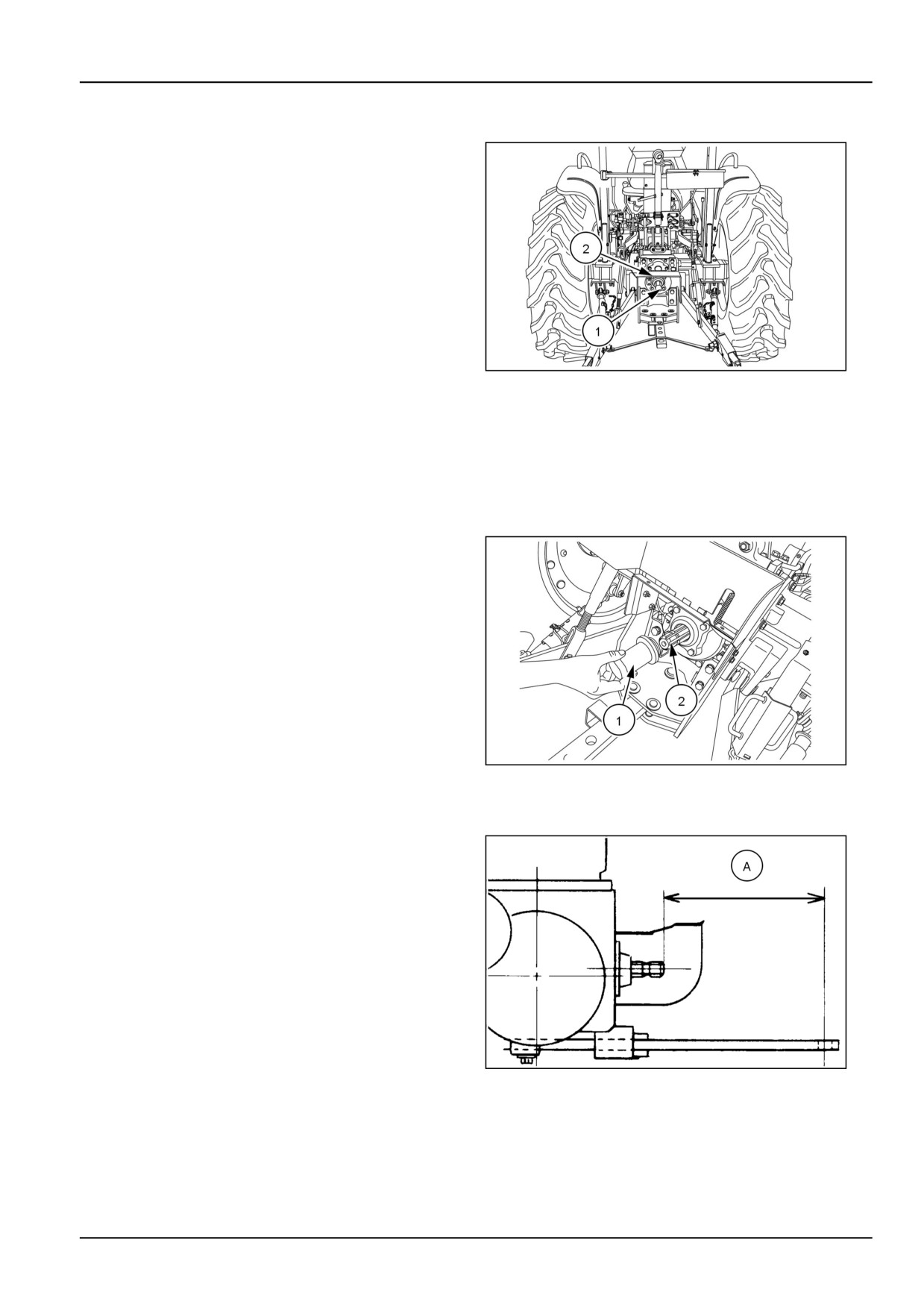
Power Take Off (PTO)
Description
The Power Take-Off (PTO) transfers engine power directly
to mounted or trailed equipment through a splined shaft
(1) at the rear of the tractor.
A PTO flip-up guard (2) is standard equipment. This guard
serves as a support for drive-line shields used with PTO
driven equipment, and provides safety for the operator.
Do not modify the guard.
The PTO system is independent, that is, the PTO may be
engaged or disengaged whether the tractor is moving or
stationary. Rotation of the PTO shaft is not affected by the
main clutch and tractor speed, but is related directly to the
speed of the engine.
GNIL14TR00560AA
1
The system utilizes the standard 6-splines shaft designed
to operate at 540 RPM.
A standard speed of 540 PTO can be obtained an engine
speed of 2575 RPM.
Attaching Power-Take Off (PTO) driven im-
plements
To connect PTO driven implement to the PTO shaft, re-
move the PTO cap (1)and store in the toolbox. Attach the
implement to the PTO shaft (2).
NOTICE: After attaching mounted implement, carefully
raise and lower using Position Control lever and check
clearances and PTO shaft slide range and proper fit.
When attaching trailered implement, ensure the drawbar
is correctly set.
GNIL14TR00515AA
2
Drawbar length adjustment
Adjust the drawbar length so that there is 349.0 mm
(13.7 in) (A) from the end of the rear PTO shaft to the
center of the drawbar pin hole.
20099087
3
6-3
6 - WORKING OPERATIONS
Power-Take Off (PTO) operation
WARNING
Avoid injury!
Observe ALL precautions listed below when operating Power Take-Off (PTO) driven equipment.
Failure to comply could result in death or serious injury.
W0435A
DANGER
Entanglement hazard!
Make sure all people and obstructions are clear of the implement before engaging the tractor Power
Take-Off (PTO).
Failure to comply will result in death or serious injury.
D0077A
1.
Check that you are using the correct PTO speed for
the implement.
2.
Follow the operator’s instructions in the operator’s
manual.
3.
Make sure that the PTO guard is installed when using
PTO driven equipment
4.
DO NOT wear loose clothing when operating PTO
driven equipment.
5.
Firmly apply the parking brake, place all control levers
in the neutral position, and block all four wheels before
operating any stationary PTO equipment.
6.
DO NOT approach, clean, or adjust PTO driven equip-
ment while the engine is still running.
7.
Stop the engine and remove the key. Wait until the
PTO and the equipment stop turning before leaving the
machine or before working on the PTO, or the equip-
ment.
8.
With the engine stopped and key removed, the PTO
brake is released and the shaft may be turned by hand
to assist in the installation or removal of the implement
shaft.
6-4
6 - WORKING OPERATIONS
Power-Take Off (PTO) engagement
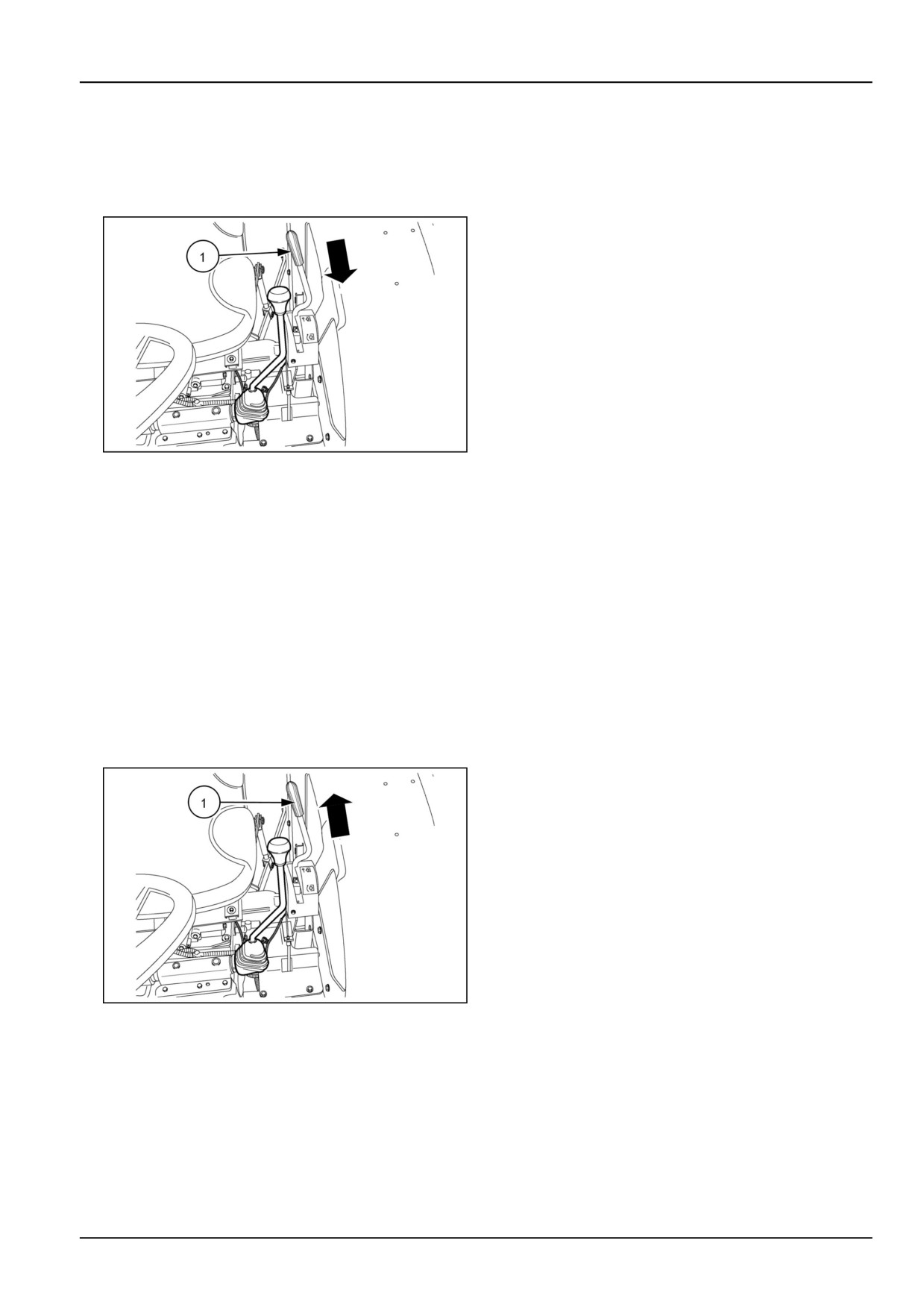
1. To engage the PTO, press the clutch pedal, and pull
lever (1) towards the operator’s seat and then push
forward until handle engages the notch in the quad-
rant.
86090124N
4
2. The PTO system is independent of the tractor ground
speed, and the following operations can be performed.
• The tractor ground travel can be stopped without stop-
ping the PTO.
• The PTO can be stopped without stopping the tractor
ground travel.
NOTE: If the operator leaves the seat without disengaging
the PTO, an alarm will sound.
Power-Take Off (PTO) disengagement
1. Pull the PTO lever (1) rearward to disengage the PTO.
86090124N
5
The PTO will stop automatically when disengaged due to
a internal frictional brake.
6-5
6 - WORKING OPERATIONS
Power-Take Off (PTO) lever positions
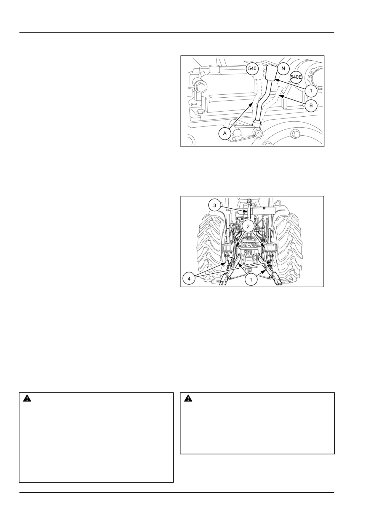
Standard speed of 540 PTO. can be obtained at an engine
speed of 2575 RPM and 540E RPM can be obtained at an
engine speed of 2016 RPM.
Shift lever (1) at position (A) to get standard PTO RPM
and to get 540E PTO shift lever (1) at position (B).
GNIL14TR00553AA
6
THREE POINT LINKAGE
Three-point linkage
Description
The three-point linkage enables semi-mounted and fully
mounted implements to be connected to the tractor, and
be controlled by the tractor hydraulic system. The three-
point linkage consists of two lower links (1) connected to
the rear axle housing. The rear end of the lower links are
connected to the lower hitch pins on the implement.
The lower links are raised and lowered by means of the lift
rods (2) connected to the lift arms . The right-hand lift rod
is readily adjusted to ease the attachment of implements
and to level the implement after attaching.
GNIL14TR00562AA
1
The top link (3) is connected to a bracket on the hydraulic
lift housing. The rear of the top link should be connected
to the upper hitch pin of a mounted implement. The top
link is also adjustable to aid implement setting.
Adjustable stabilizers (4) are connected to each lower link.
The stabilizers limit side to side movement of the lower
links and attached implement. Adjust stabilizers so that
there is not any interference between the tires and the
lower links.
Attaching three-point equipment
WARNING
WARNING
Entanglement hazard!
Collision hazard!
Before attaching or detaching equipment or
Always make sure the area behind the ma-
changing the Power Take-Off (PTO) shaft: 1)
chine is clear of all persons, animals, and ob-
Apply the parking brake. 2) Move all controls
structions BEFORE backing up.
to neutral and PTO control knob to the dis-
Failure to comply could result in death or se-
engaged position. 3) Stop the engine and re-
rious injury.
W0232A
move the key. 4) Wait for the PTO shaft to stop
turning before leaving the cab.
Failure to comply could result in death or se-
rious injury.
W0323A
6-6
6 - WORKING OPERATIONS
NOTE: Before attaching implements read the following
WARNING
text carefully.
Pinch hazard!
Always use the position control lever when
attaching, detaching, or transporting imple-
ments.
Failure to comply could result in death or se-
rious injury.
W0466A
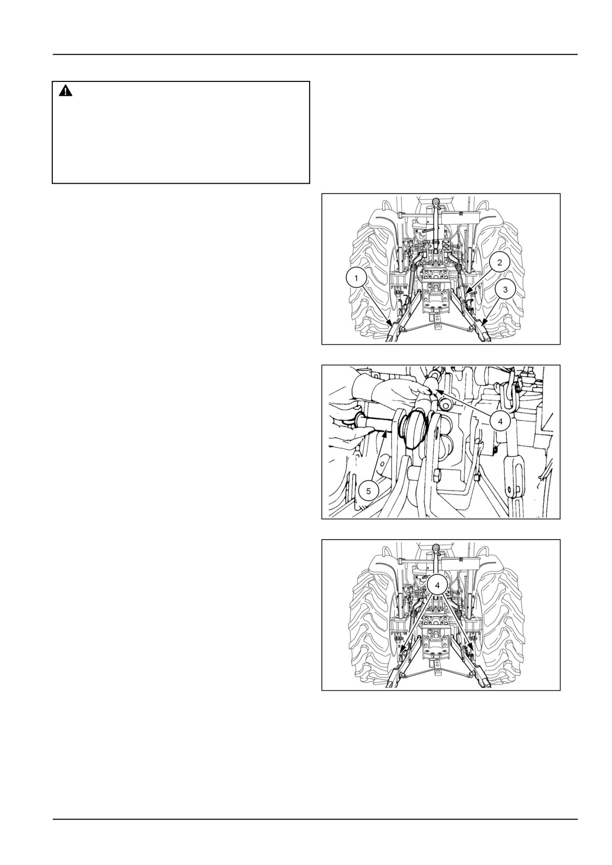
Most implements can be attached to the tractor as follows:
Position the tractor so that the lower link hitch points are
level with and slightly ahead of the implement hitch pins.
Carefully bring the tractor rearwards to match the trac-
tor and implement hitch points. First attach the left-hand
lower link (1) then by adjusting the levelling box (2) attach
the right-hand lower link (3).
GNIL14TR00562AA
1
Lengthen or shorten the top link (4) until the implement
mast pin (5) can be inserted through the mast and upper
link of the implement.
20108789
2
Adjust stabilizers (4) to limit side to side movement of the
lower links and attached implement. Adjust stabilizers so
that there is not any interference with tires and lower links
when moving attached implement side to side.
NOTICE: When attaching mounted or semi mounted im-
plement to the three-point linkage, ensure that there is ad-
equate clearance between the implement and the rear of
the tractor. The clearances in the raised position should
be checked by raising the implement carefully with posi-
tion control lever. With the implement fully raised there
must be at least 100 mm (4 in). clearance between the
implement and the nearest part of the tractor.
GNIL14TR00562AA
3
NOTICE: Ensure that the telescoping stabilizers (4) are
adjusted to suit the equipment. Remove the swinging
drawbar, if close mounted equipment is being attached.
6-7
6 - WORKING OPERATIONS
Detaching three-point equipment
• When detaching implement, the procedure is the re-
verse of attaching. The following hints will make de-
taching easier and safer.
• Always park the implement on a level, firm surface.
• The implement should be supported so that the imple-
ment cannot tip or fall when detached from the tractor.
• Always relieve all hydraulic pressure in any remote
cylinders before detaching.
6-8
6 - WORKING OPERATIONS
Lift rods, lower links and top link
WARNING
Crushing hazard!
Before disconnecting a lift rod from the lower
link, lower the attached implement to the
ground, and stop the engine. Make sure the
attached implement is correctly supported
and no pressure remains in the hydraulic
system before removing the lift rod securing
pins.
Failure to comply could result in death or se-
rious injury.
W0034A
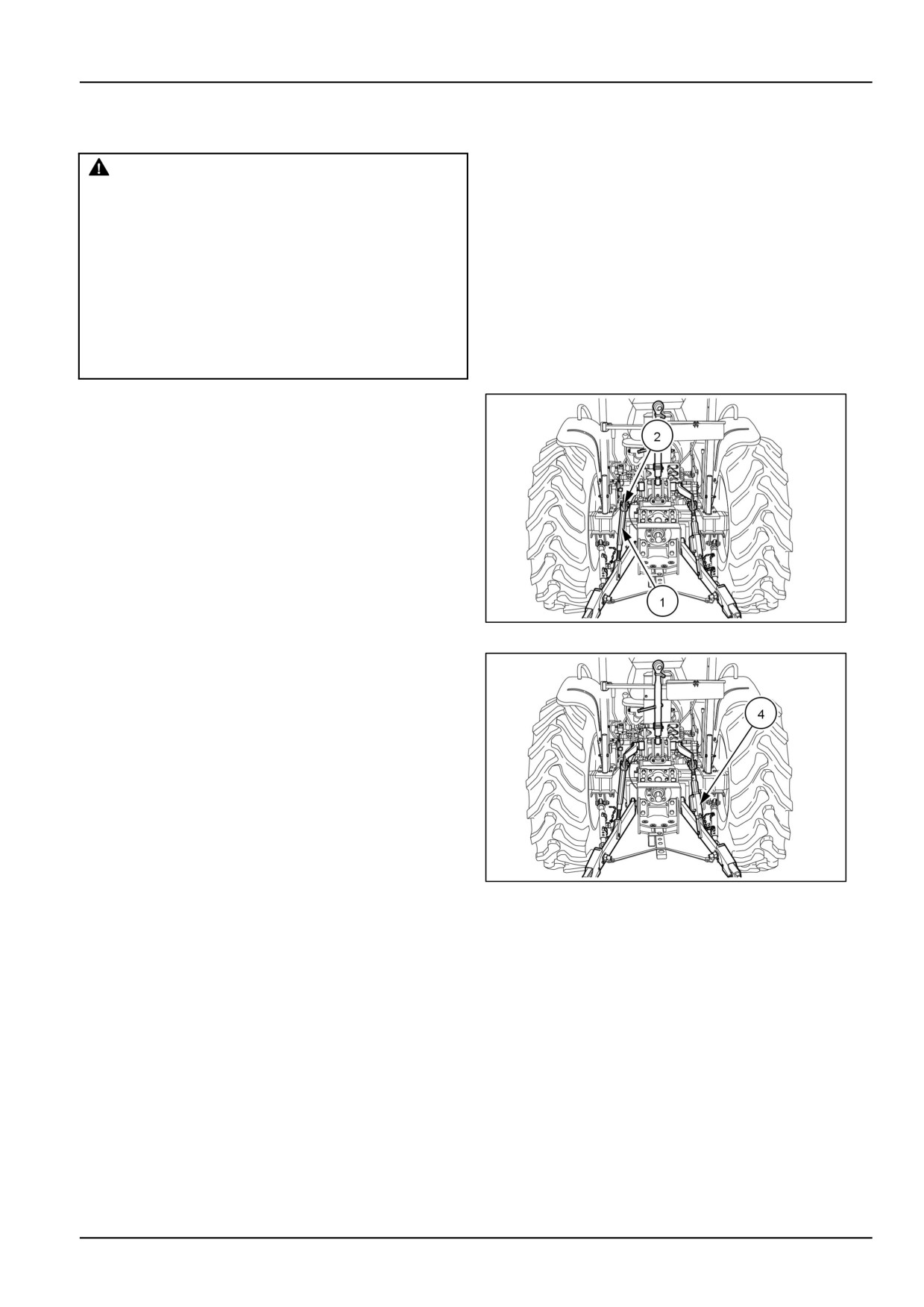
Left-hand Lift Rod
NOTE: Left-hand lift rod (1) is adjustable but must be re-
moved from the lift arm before length can be changed.
To lengthen or shorten the left-hand lift rod (1):
1. Remove retaining clip (2) and pin (2) from lift rod.
2. Rotate the top half of the lift rod clockwise to reduce
length.
3. Rotate the top half of the lift rod counter-clockwise to
increase the length.
GNIL14TR00562AA
1
Right-hand Lift Rod
NOTE: The right-hand lift rod is readily adjustable even
when connected between lift arm and lower link.
To lengthen or shorten the right-hand lift rod, lift the jug
handle up (4) and rotate clockwise to increase the length
and counter-clockwise to reduce the length.
GNIL14TR00562AA
2
6-9
6 - WORKING OPERATIONS
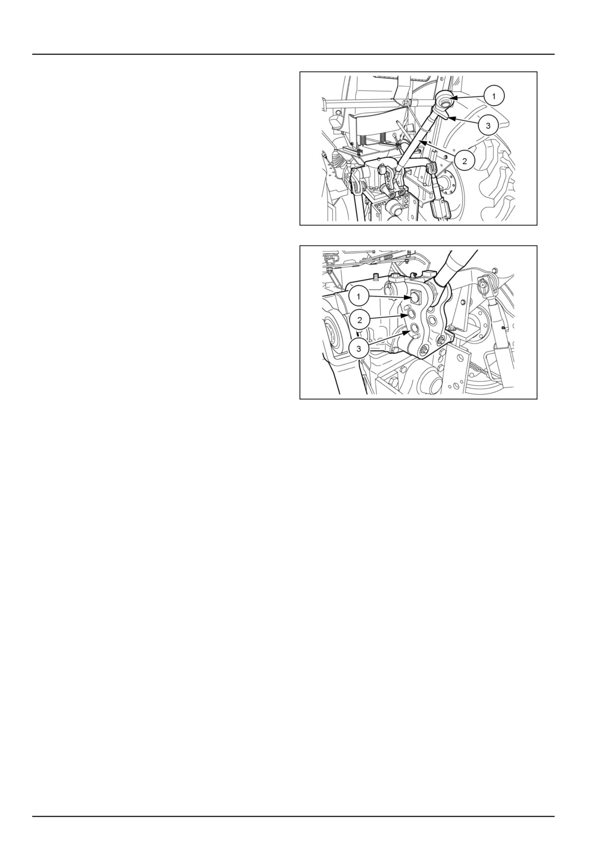
Top Link
To adjust the top link length:
1. Hold the link end (1) and rotate the sleeve (2) to
lengthen or shorten the top link.
2. Tighten the lock (3) against the top link sleeve to pre-
vent unwanted rotation of sleeve when in work.
86090128N
3
Hydraulic draft sensing spring adjustment
When operating in Draft Control, the top link and hydraulic
draft sensing spring transmit draft signals to the control
valve within the hydraulic system. The top link attachment
to the draft sensing spring affects draft signals.
The draft sensing spring bracket contains three holes for
attaching the top link. The top hole (1) is recommended
for light draft loads and light equipment. With the top link in
the top hole, the hydraulic system is more sensitive to draft
signals. Use the middle hole (2) for heavier draft loads
and equipment, and the bottom hole (3) for the heaviest
loads. With the top link in the bottom hole, the hydraulic
system is less sensitive to draft signals.
86090127N
4
NOTICE: When mounting a category I, three-point hitch
mounted implement, it may be necessary to remove
the drawbar and drawbar support to obtain clearance
between tractor and implement.
6-10
6 - WORKING OPERATIONS
HYDRAULIC SYSTEM
Hydraulic systems - Operating
Hydraulic Power Lift (HPL)
This is a closed-center hydraulic system, where a hy-
draulic gear pump constantly circulates hydraulic oil
through the hydraulic system. Transmission lubrication
oil is used as the hydraulic oil. The system allows the
operator to select any of the three controls (position
control, draft control, and float control).
GNIL14TR00580AA
1
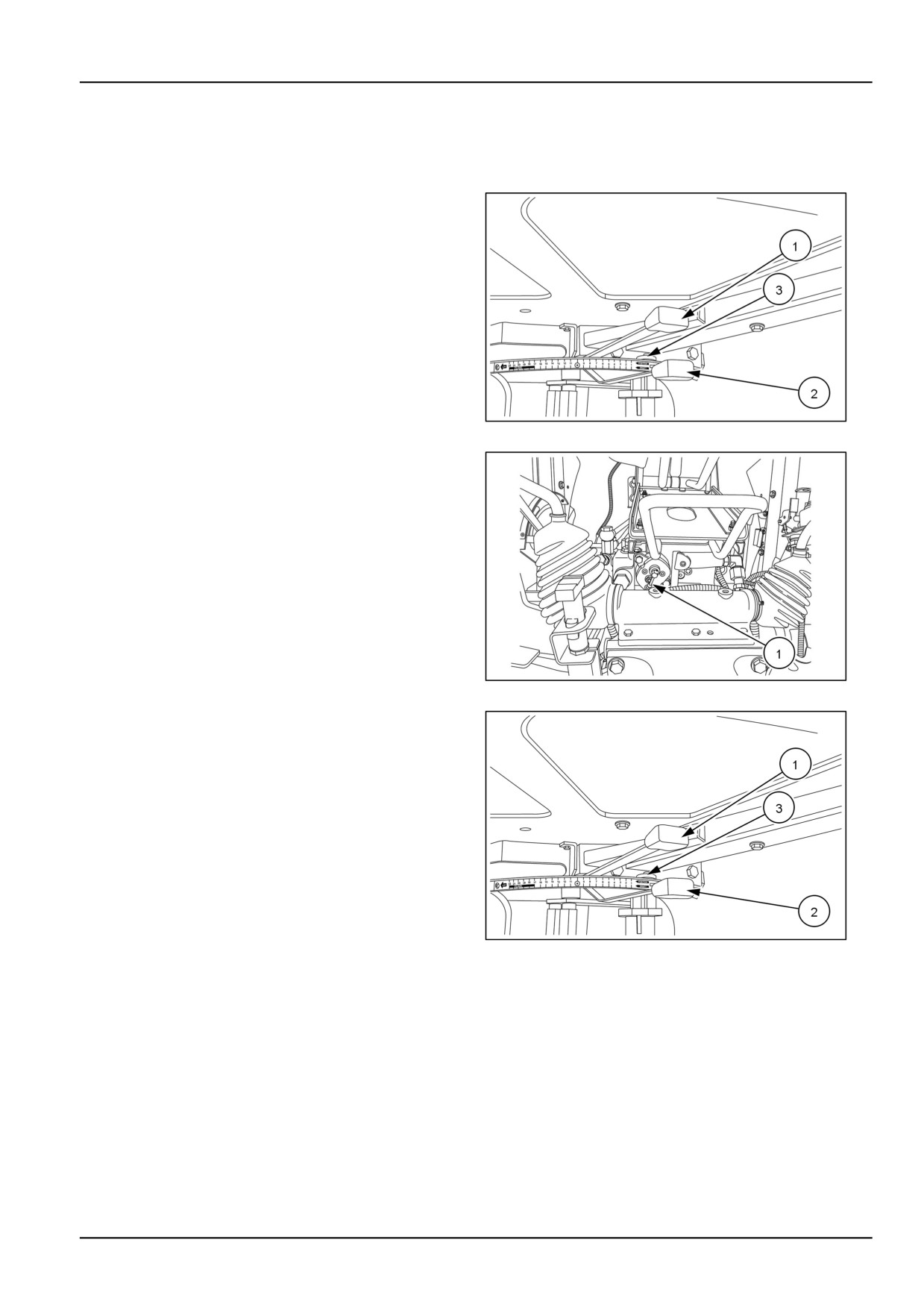
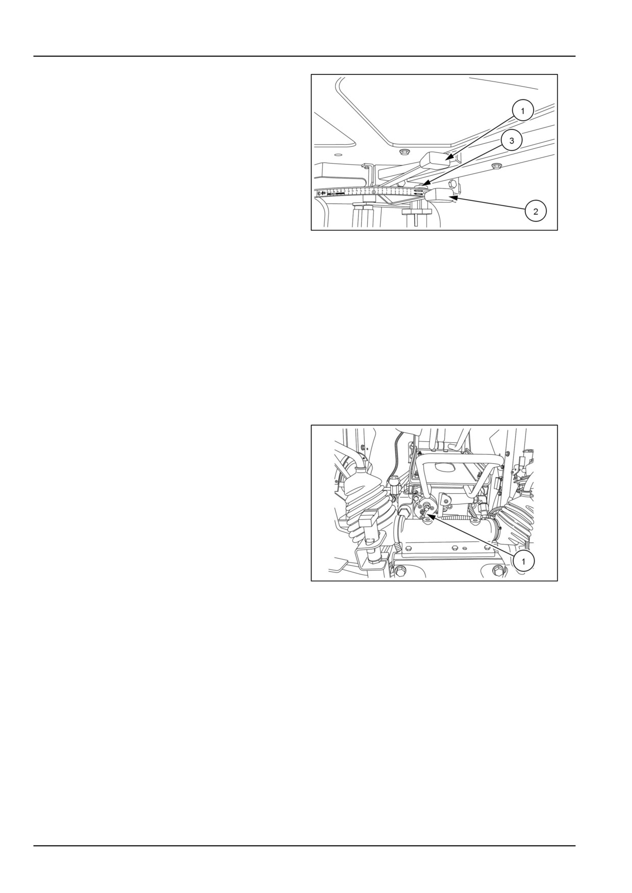
The hydraulic Power Lift (HPL)system is operated by the
position control lever (1), draft control lever (2), see, 1 and
the response control (3), see 1.
NOTICE: Some mounted or semi-mounted equipment
may interfere with and cause damage to tractor sheet
metal. To avoid damage check for clearance between
tractor and implements.
GNIL14TR00554AA
2
Position control
The position control lever (1) sets the lower position of the
hydraulic lift. Position control is best for fixed-level imple-
ments that operate above the ground, such as mowers,
rakes, and sprayers. Position control keeps the equip-
ment at one position at all times, so it is not recommenced
for any ground-engaging equipment, unless the field is
very flat and the soil is very consistent.
To set the position control, move the draft control lever (2)
to its full forward position. Then set the implement position
lower by moving the position control lever, forward, or set
implement position higher by moving the lever rearward.
When operating in position control, the tractor and imple-
GNIL14TR00580AA
3
ment become a single unit that reacts to changing terrain
as one piece of equipment. Once you have position con-
trol set, you can raise and lower the attached implement
at the end of each pass.
You can limit the range of manual position lever operation
by moving and tightening the stop (3).
6-11
6 - WORKING OPERATIONS
Draft control
The draft control lever (1) sets the desired depth of the
attached implement. Draft control is best when using im-
plements that operate in the ground, such as plows, har-
rows, or cultivators. The draft loading on the implement
increases and decreases as the working depth or the soil
resistance changes.
To set the draft control, move the position control lever
(2) to the full forward position. Then set the implement
draft depth lower by moving the draft control lever forward,
or set implement draft depth higher by moving the lever
rearward.
Implement depth will be proportional to draft, depending
GNIL14TR00580AA
4
on the soil conditions. With draft control, the lift keeps the
tractive effort steady automatically.
You can limit the range of manual draft lever operation by
moving and tightening the stop (3).
Combined draft and position control
You can use Draft and Position Control together to operate
in Draft Control but prevent the implement from sinking
excessively when soil conditions change. First set the
draft control lever (1) with the position control lever (2)
fully forward. Then move the position control lever back
until the link arms start to rise. The position control lever
sets the lowered position of the hydraulic lift.
Response control
The response control knob (1) varies the speed of drop of
the lower links.
Clockwise rotation -- Decreases speed of drop
Counter-clockwise rotation - Increases speed of drop
NOTICE: To lock implements in transport position when
driving on road, fully raise Position Control lever (2), see
5 and screw in (rotate clockwise) knob (1), see 5.
GNIL14TR00554AA
5
6-12
6 - WORKING OPERATIONS
Rear remote control valve(s)
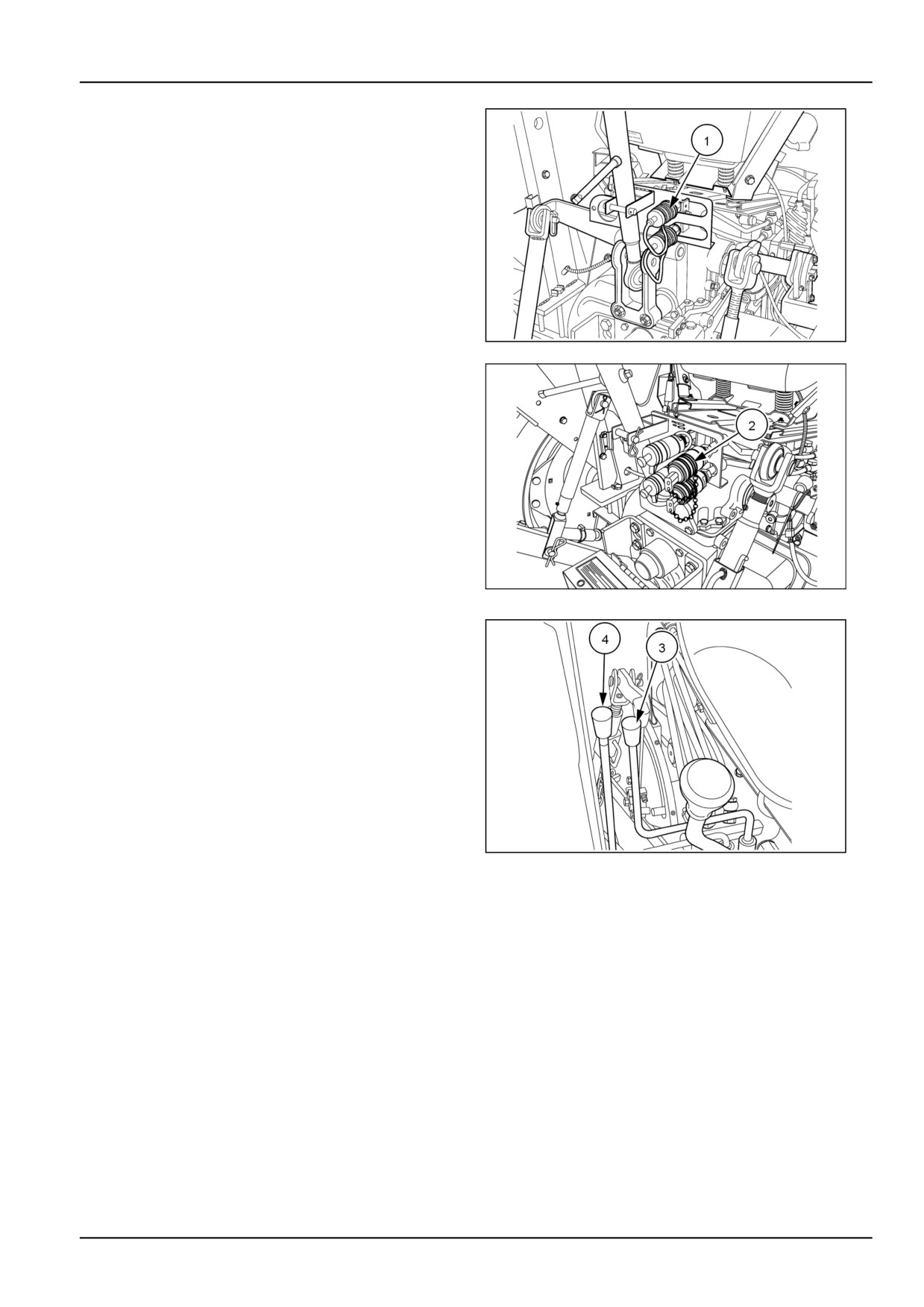
The number 1 rear remote valve (1) is standard equipment
and number 2 valve (2) is an optional dealer installed ac-
cessory.
86096199N
6
93103969
7
To operate the remote control valve, move control lever
(3) for valve number 1 and (4) for valve number 2. Move
control lever rearward to extend implement cylinder and
forward to retract implement cylinder.
If the valve is a float/detent style valve, move the control
lever to the full forward position in order to place the valve
into the detent “Float” position.
86071888N
8
6-13
6 - WORKING OPERATIONS
WHEEL TRACK ADJUSTMENT
Wheel tread settings
Front wheel tread adjustment
1.
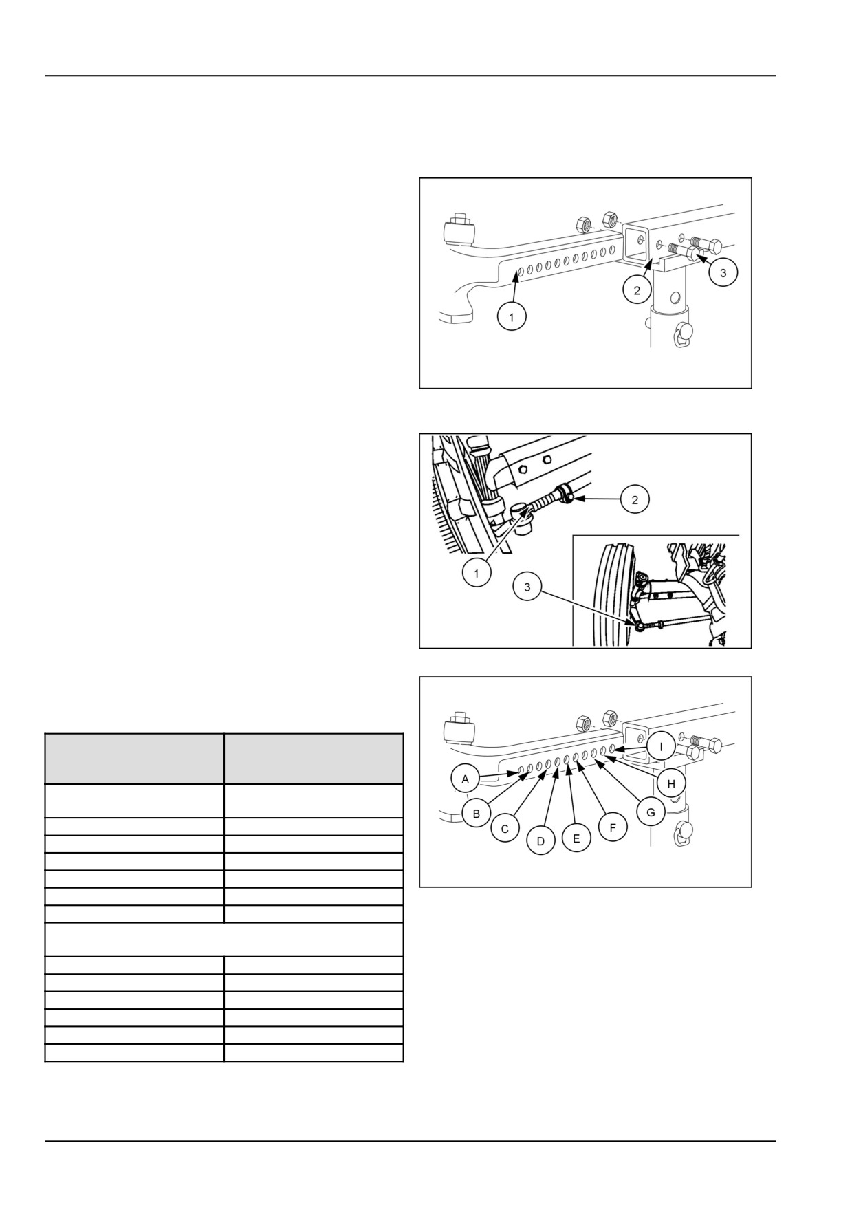
The front axle consists of a hollow center beam (1)
with a telescopic section (2) at each end. Seven holes
at 50 mm (1.97 in) intervals are provided in the tele-
scopic sections for adjustment purposes. Adjustment
of the front wheel track width is effected by extending
both ends of the axle equally.
2.
To extend the axle, apply the hand brake and place
blocks at the front and rear of the rear wheels. Jack up
the front axle and place on axle stands. Remove the
securing bolts, (3), securing the left-hand telescopic
section to the center beam.
GNIL14TR00500AA
1
3.
Repeat the same for the right-hand side of the axle.
4.
The tie rod is adjustable and consists of a central,
hollow tube with a solid extendible section at each
end. The left-hand end of the tie rod has a number
of notches (1) at 50 mm (1.97 in) intervals
5.
A locating bolt (2) passes through a clamp and one
of the notches in the solid section and locks the tie
rod assembly at the desired length. Additionally, the
right-hand end of the tie rod is threaded (3) to provide
fine adjustment of toe-in.
6.
Remove the locating bolt (2) from the left-hand end of
the tie rod. This will permit the tie rod to extend or
retract freely.
76099305N
2
7.
Reset both axle telescopic sections. Passing the se-
curing bolts through the center beam and telescopic
sections, as indicated in 3 and table below:
Securing
2WD
Bolt
Locations
2WD
7.50 - 16
Dished In
AC
1424 mm
BD
1524 mm
CE
1624 mm
DF
1724 mm
EG
1824 mm
GNIL14TR00500AA
3
FH
1924 mm
2WD
Dished Out
AC
1472 mm
BD
1572 mm
CE
1672 mm
DF
1772 mm
EG
1872 mm
FH
1972 mm
6-14
6 - WORKING OPERATIONS
NOTE: The tread settings shown are approximate. The
front wheel discs are off-set, relative to the center line of
the rim. The tread settings in the table are with the dished
side of the wheel nearest the axle hub. If the front wheels
are reversed on the hubs the tread settings shown in the
table will be increased by approximately 25 mm (0.98 in).
8. Tighten the nuts on the axle extension securing bolts
to 118 N·m (87 lb ft)
9. With both front wheels parallel, install the locating bolt
(2) in the nearest aligning notch in the tie rod. Tighten
the nut on the locating bolt to 24.5 N·m (18 lb ft)
Tractor model
Front wheel bolt torque
320.0 N·m (236.0 lb ft)
NOTE: Re-check all torque settings after 50 h of opera-
tion.
Front wheel toe-in
After resetting the track width, the front wheel toe-in
may require adjustment. For correct operation, the front
wheels should be parallel or toe-in slightly.
NOTICE: Incorrect toe-in setting may result in abnormal
wear of front tires.
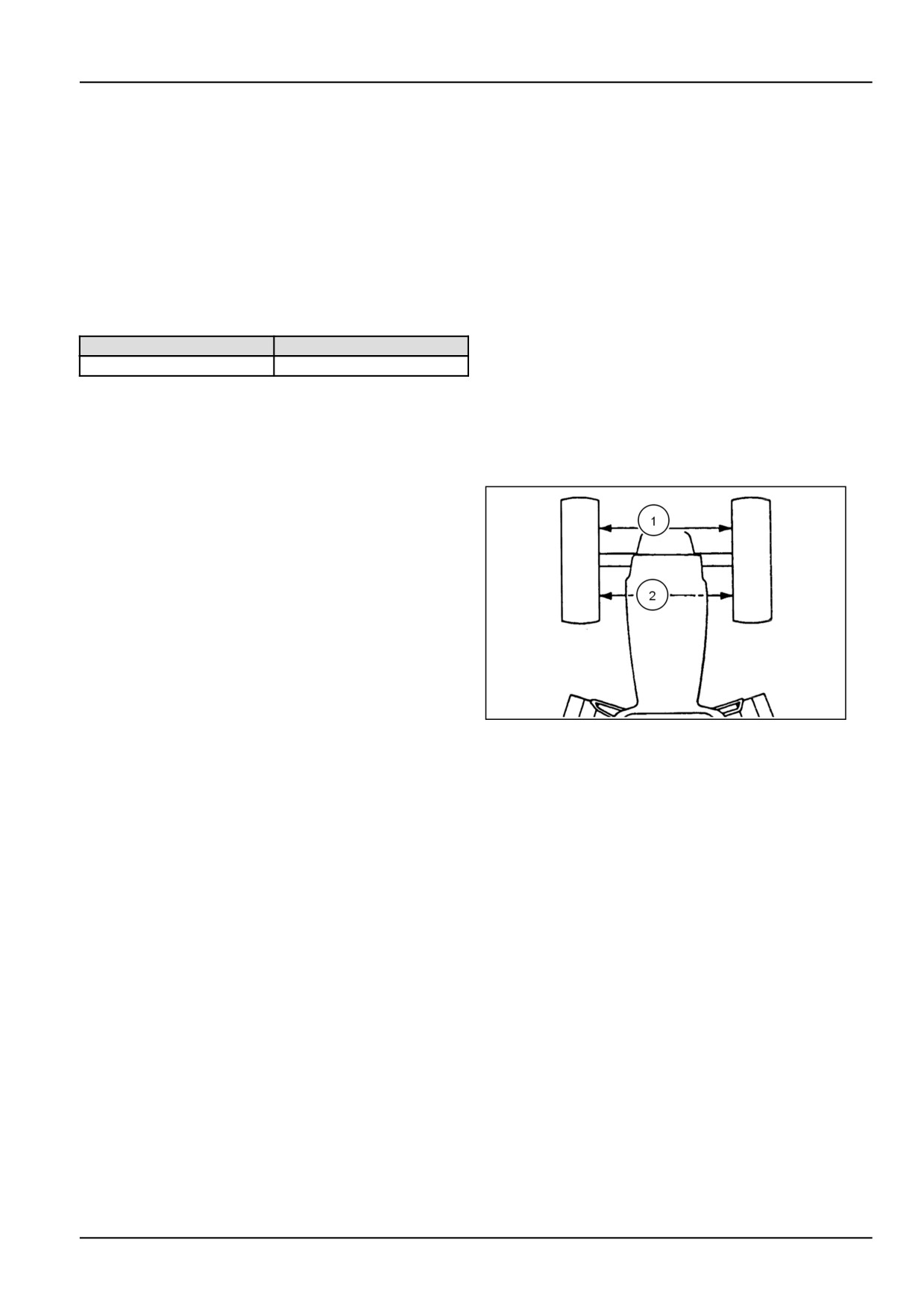
To measure the toe in proceed as follows
1. Measure the distance (1) between the wheel rims at
hub height at the front of the wheels. Rotate both front
wheels by 180 ° and check the measurements again,
20108791
4
this time at the rear of the wheels (2)
2. This will eliminate wheel rim run-out errors. The cor-
rect toe-in setting is 0-5 mm, i.e., the measurement
taken at the front of the rims should be the same as
the rear or be smaller by up to 5 mm (0.20 in)
6-15
6 - WORKING OPERATIONS
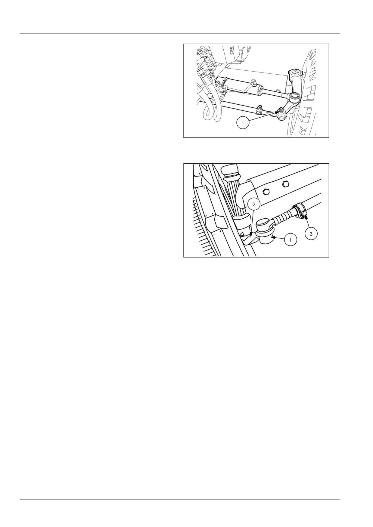
Tie Rod - Steering (Right-hand side - Illus-
trated)
1. The tie rod located behind the axle must be disen-
gaged to permit adjustment of the axle.
2. The tie rod is telescopic and consists of a central hol-
low tube with a solid extendible section at each end.
3. Remove the locating bolt (1) from both ends of the tie
rod.
4. The position for the setting of the steering cylinder will
also change respectively.
5. Left-hand and right-hand axle telescopic sections,
86090130N
5
passing the securing bolts through the center beam
and telescopic sections, as indicated in 3, see chart.
6. Remove the nut (1) at the right-hand end of the tie rod
and withdraw tie rod from arm (2)
7. Loosen the bolt (3) and rotate the threaded end to
shorten or lengthen tie rod assembly until the toe-in
is correct. Tighten all bolts/nuts securely.
20108792
6
6-16
6 - WORKING OPERATIONS
WARNING
Roll-over hazard!
Never operate the machine with a loose wheel
rim or disc. Always tighten nuts to the speci-
fied torque value and at the recommended in-
tervals.
Failure to comply could result in death or se-
rious injury.
W0346A
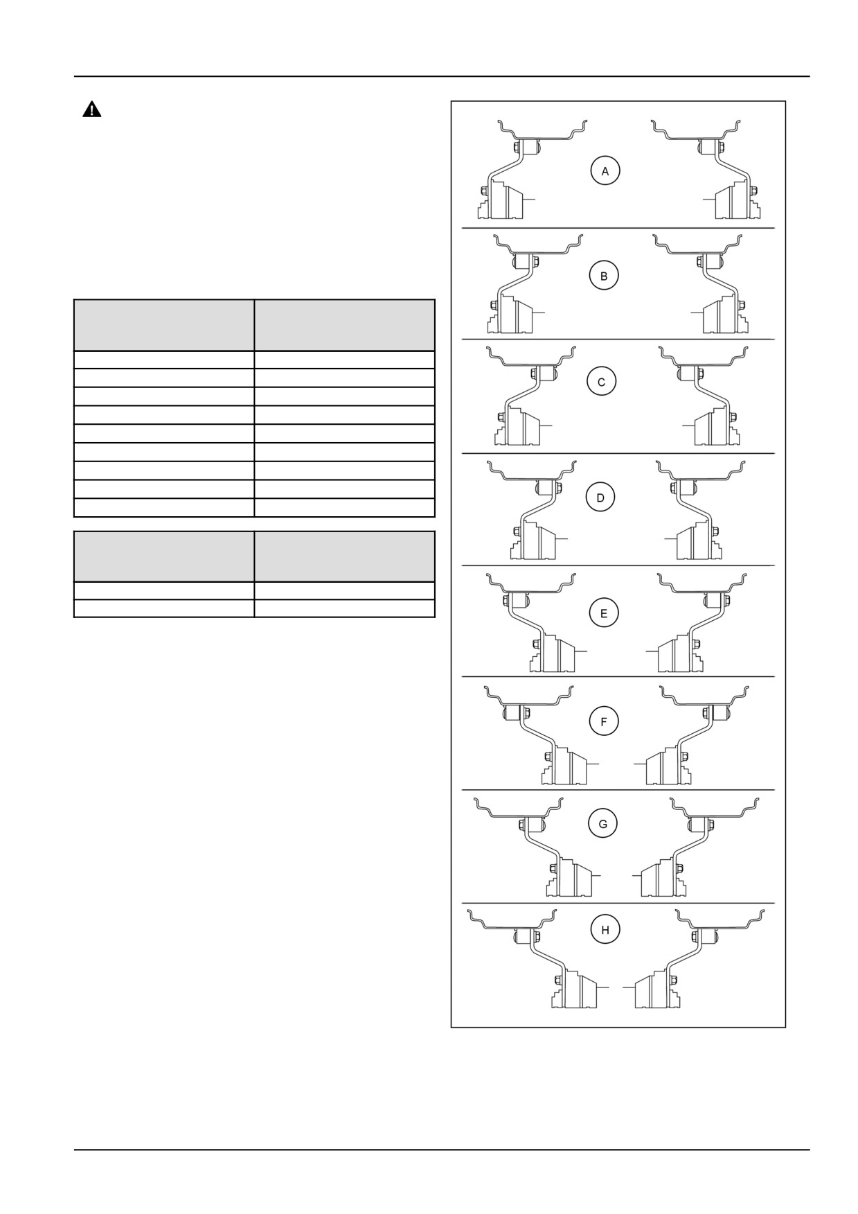
Four-wheel drive (4WD) tread setting
4WD
4WD
Front
Tread
Axle
Setting
9.5 —24
(A)
NA
(B)
NA
(C)
NA
(D)(Standard)
1558.0 mm (61.3 in)
(E)
1522.0 mm (59.9 in)
(F)
1630.0 mm (64.2 in)
(G)
1650.0 mm (65.0 in)
(H)
1758.0 mm (69.2 in)
4WD
Front
Axle
R4 12.5/80-18
Front
1532 mm
Front wheel bolt torque: 192.0 N·m (141.6 lb ft)
76096164N-85X23
7
6-17
6 - WORKING OPERATIONS
Rear wheel tread adjustment
WARNING
Roll-over hazard!
Never operate the machine with a loose wheel
rim or disc. Always tighten nuts to the speci-
fied torque value and at the recommended in-
tervals.
Failure to comply could result in death or se-
rious injury.
W0346A
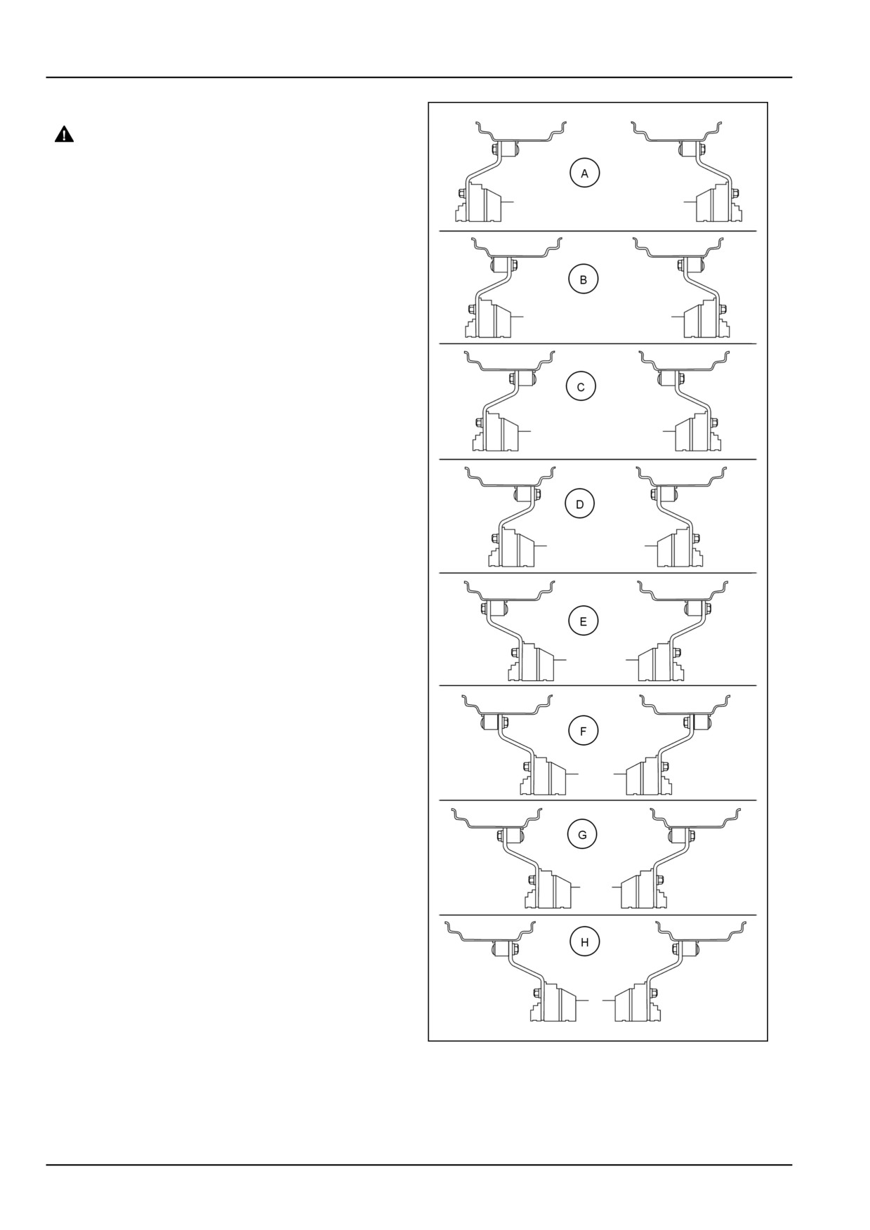
Rear wheel track adjustment is affected by changing the
wheel rim relative to the center disc, the rim and/or the
disc relative to the axle hub or by interchanging the rear
wheels.
The sectioned drawings shown in the table illustrate the
wheel rim and disc positions viewed from rear of the trac-
tor relative to the hub at various track width settings. Track
width (the distance between the center of the tires) are
nominal and may vary by as much as 13 mm (0.5 in).
NOTICE: When interchanging left-hand and right-hand
wheel assemblies, ensure the “V” of the tire tread remains
pointing in the direction of forward travel of tractor for bet-
ter traction.
NOTICE: With certain options and/or tire sizes narrower
track settings may not be possible due to minimal clear-
ance between tires and fenders or equipment.
When installing or adjusting a wheel, tighten the bolts to
the following torques recheck after driving the tractor for 1
hour and 8 hours operation and thereafter at the 50 hour
intervals:
Rear disc to hub bolts
192 N·m (142 lb ft)
Rear disc to rim nuts
239 N·m (176 lb ft)
76096164N-85X23
8
6-18

6 - WORKING OPERATIONS
Rear Axle
2WD
2WD & 4WD
4WD
Configuration
13.6 R 28
14.9 R 28
R4 18.4X24
(A)
N/A
N/A
N/A
(B)
N/A
N/A
1438.0 mm (56.6 in)
(C)
N/A
N/A
N/A
(D)
1336.0 mm (52.6 in)
1336.0 mm (52.6 in)
N/A
(E)
1420.0 mm (56 in)
1420.0 mm (56 in)
N/A
(F)
1534.0 mm (60.4 in)
1534.0 mm (60.4 in)
N/A
(G)
1623.0 mm (64 in)
1623.0 mm (64 in)
N/A
(H)
1737.0 mm (68.4 in)
1737.0 mm (68.4 in)
N/A
BALLASTING AND TIRES
Ballasting and tires
Selecting Ballast
• Type and size of tires
WARNING
• Tire Pressure
Roll-over hazard!
Do not use more ballast than needed. Excess ballast
A tractor without adequate ballasting, wheel
should be removed when the excess ballast is not re-
base, and tire spacing can be unstable when
quired.
operating the implement on an incline. Read
the tractor operator's manual for exact in-
Too little Ballast
structions. If instructions are not available,
you must conduct suitable tests in safe con-
• Rough ride
ditions to assess stability.
Failure to comply could result in death or se-
• Excessive wheel slip
rious injury.
W0190A
• Power loss
• Tire wear
When tractor horsepower loads vary the optimum weight
• Excessive fuel consumption
of the tractor will change. This means that ballast may
• Lower productivity
have to be added or removed to maintain the best tractor
performance. Proper ballast will greatly improve tractor
operation and ride.
Too much Ballast
The amount of ballast required is effected by
• Higher maintenance costs
• Weight of tractor
• Increased driveline wear
• Soil and Traction condition
• Power loss
• Type of implement fully-mounted, semi-mounted or
• Increased soil compaction
trailed.
• Excessive fuel consumption
• Working speed.
• Lower productivity
• Tractor horsepower & load
6-19
6 - WORKING OPERATIONS
For maximum tractor performance in heavy draft condi-
NOTICE: Only sufficient weight should be added to pro-
tions weight should be added to the tractor in the form of
vide traction and stability. Adding more weight than nec-
liquid ballast, cast iron weights or combination of both.
essary results in unnecessary loads being put on the trac-
tor and higher fuel consumption. When adding weight ad-
Front end ballast may be required for stability and steering
here to the maximum tire capacity loading stated in the
control when weight is transferred from the front wheels to
tables at the end of this Section. If further information
the rear wheels as the implement is raised by the tractor
or assistance is required on tractor weighing consult your
three-point linkage.
Authorized Dealer.
WARNING
When a rear mounted implement is raised to the transport
position, the weight on the front wheels should be at least
Roll-over hazard!
20% of total tractor weight.
If proper stability cannot be achieved within
the following weight limitations, reduce the
Add front-end ballast as required, for stability during op-
load on the machine until you achieve stabil-
eration and transport. Ballasting of the front end may not
ity.
always provide adequate stability if the tractor is operated
Failure to comply could result in death or se-
at high speed on rough ground. Reduce tractor speed and
rious injury.
W0468A
be cautious under these conditions.
When using front mounted equipment, it may be neces-
sary to add weight to the rear wheels to maintain traction
and stability.
6-20
6 - WORKING OPERATIONS
Ballast limitations
Ballast should be limited by the tire capacity or tractor ca-
pacity. Each tire has a recommended carrying capacity,
which should not be exceeded.
NOTICE: Do not exceed the tractor gross vehicle weight
of 2300.0 kg (5070.6 lb) . This can cause overload con-
dition that may invalidate the warranty and may exceed
the load rating of the tires. The maximum recommended
gross vehicle weight is the weight of the tractor plus bal-
last plus any mounted equipment/ implement in the raised
position.
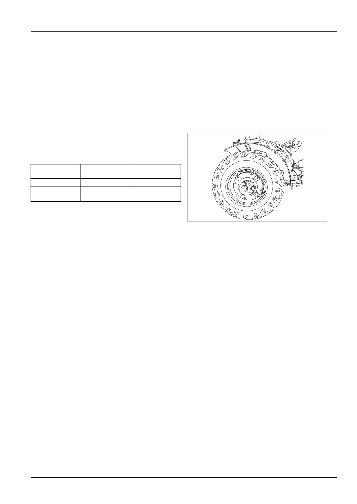
Rear wheel weights (optional)
The rear wheels are fitted with cast iron wheel weights,
weighing 40.0 kg (88.2 lb) each.
Tire Size
No. Weights per
Total added
wheel
weight per wheel
13.6-28
2 X 40
40.0 kg (88.2 lb)
14.9-28
2 X 40
40.0 kg (88.2 lb)
18.4-24
2 X 40
40.0 kg (88.2 lb)
Tightening torque:
GNIL14TR00561AA
1
Rear wheel weight to rear wheel disc:
230 ± 13 N·m (170 ± 10 lb ft).
Rear wheel weight to rear wheel disc:
230 ± 13 N·m (170 ± 10 lb ft).
6-21