New Holland Tractor Workmaster 50 / Workmaster 60 / Workmaster 70 / Tier 4B (final). SERVICE MANUAL - page 27

2 - SAFETY INFORMATION
Proposition 65
BT09A213
1
2-9
2 - SAFETY INFORMATION
Ecology and the environment
Soil, air, and water quality is important for all industries
Battery recycling
and life in general. When legislation does not yet rule the
treatment of some of the substances that advanced tech-
Batteries and electric accumulators contain several sub-
nology requires, sound judgment should govern the use
stances that can have a harmful effect on the environ-
and disposal of products of a chemical and petrochemical
ment if the batteries are not properly recycled after use.
nature.
Improper disposal of batteries can contaminate the soil,
groundwater, and waterways. NEW HOLLAND strongly
Familiarize yourself with the relative legislation applica-
recommends that you return all used batteries to a NEW
ble to your country, and make sure that you understand
HOLLAND dealer, who will dispose of the used batteries
this legislation. Where no legislation exists, obtain in-
or recycle the used batteries properly. In some countries,
formation from suppliers of oils, filters, batteries, fuels,
this is a legal requirement.
anti-freeze, cleaning agents, etc., with regard to the ef-
fect of these substances on man and nature and how to
safely store, use, and dispose of these substances. Your
NEW HOLLAND dealer can also provide assistance.
Helpful hints
•
Avoid the use of cans or other inappropriate pressur-
ized fuel delivery systems to fill tanks. Such delivery
systems may cause considerable spillage.
•
In general, avoid skin contact with all fuels, oils, acids,
solvents, etc. Most of these products contain sub-
stances that may be harmful to your health.
NHIL14GEN0038AA
1
•
Modern oils contain additives. Do not burn contami-
nated fuels and or waste oils in ordinary heating sys-
Mandatory battery recycling
tems.
NOTE: The following requirements are mandatory in
•
Avoid spillage when you drain fluids such as used en-
Brazil.
gine coolant mixtures, engine oil, hydraulic fluid, brake
fluid, etc. Do not mix drained brake fluids or fuels with
Batteries are made of lead plates and a sulfuric acid so-
lubricants. Store all drained fluids safely until you can
lution. Because batteries contain heavy metals such as
dispose of the fluids in a proper way that complies with
lead, CONAMA Resolution 401/2008 requires you to re-
all local legislation and available resources.
turn all used batteries to the battery dealer when you re-
•
Do not allow coolant mixtures to get into the soil. Col-
place any batteries. Do not dispose of batteries in your
lect and dispose of coolant mixtures properly.
household garbage.
•
Do not open the air-conditioning system yourself. It
Points of sale are obliged to:
contains gases that should not be released into the at-
mosphere. Your NEW HOLLAND dealer or air-condi-
• Accept the return of your used batteries
tioning specialist has a special extractor for this pur-
• Store the returned batteries in a suitable location
pose and can recharge the system properly.
• Send the returned batteries to the battery manufacturer
•
Repair any leaks or defects in the engine cooling sys-
for recycling
tem or hydraulic system immediately.
•
Do not increase the pressure in a pressurized circuit as
this may lead to a component failure.
•
Protect hoses during welding. Penetrating weld splatter
may burn a hole or weaken hoses, allowing the loss of
oils, coolant, etc.
2-10
2 - SAFETY INFORMATION
Safety signs
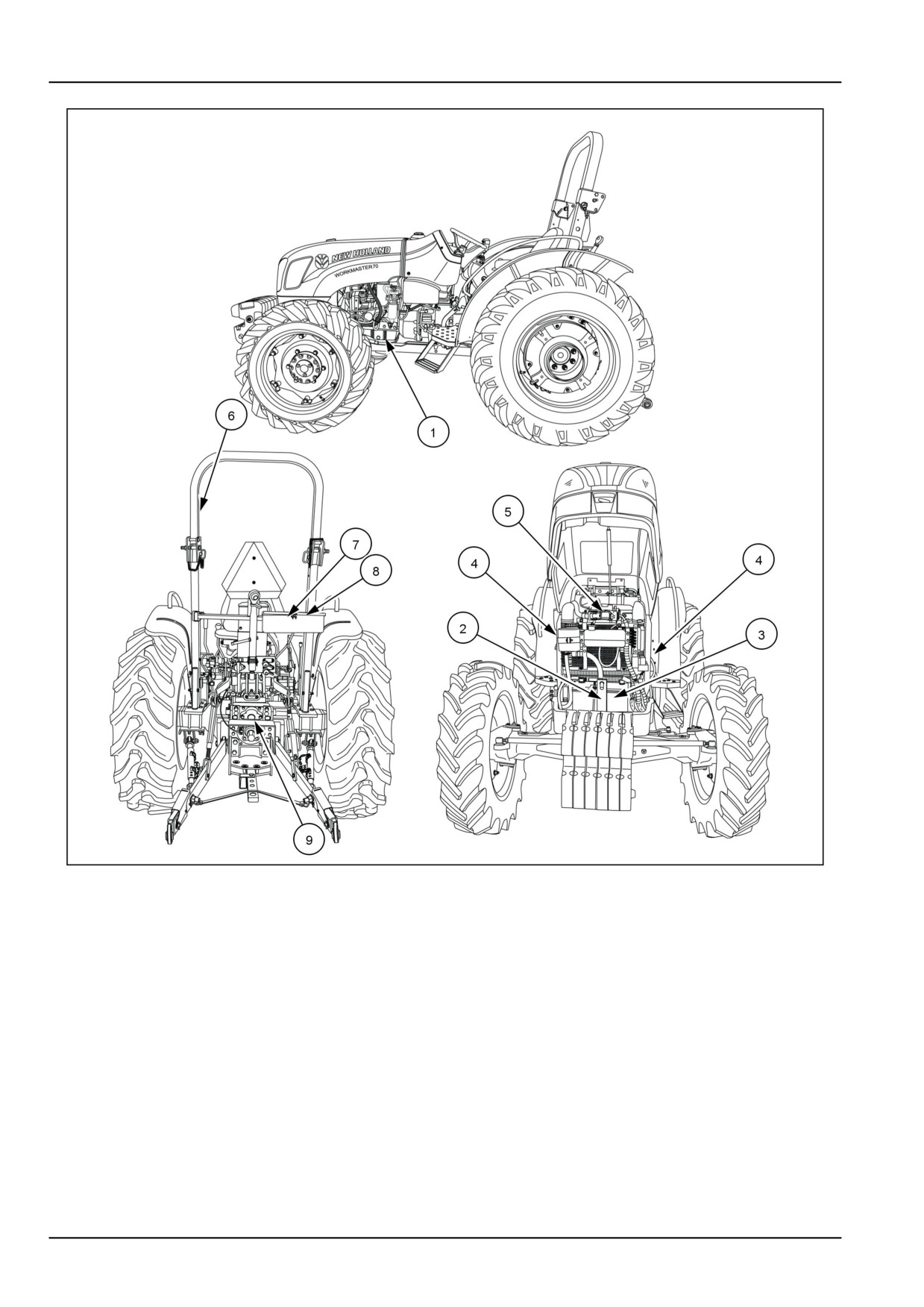
The following safety signs are placed on your machine as a guide for your safety and for those working with you. Walk
around the machine and note the content and location of these safety signs before operating your machine.
Keep safety signs clean and legible. Clean safety signs with a soft cloth, water, and a gentle detergent. Do not use
solvent, gasoline, or other harsh chemicals. Solvents, gasoline, and other harsh chemicals may damage or remove
safety signs.
Replace all safety signs that are damaged, missing, painted over, or illegible. If a safety sign is on a part that is
replaced, make sure the safety sign is installed on the new part. See your dealer for replacement safety signs.
Safety signs that display the “Read Operator’s Manual” symbol are intended to direct
the operator to the operator’s manual for further information regarding maintenance,
adjustments, or procedures for particular areas of the machine. When a safety sign
displays this symbol, refer to the appropriate page of the operator’s manual.
2-11
2 - SAFETY INFORMATION
GNIL14TR00551HA
1
2-12
2 - SAFETY INFORMATION
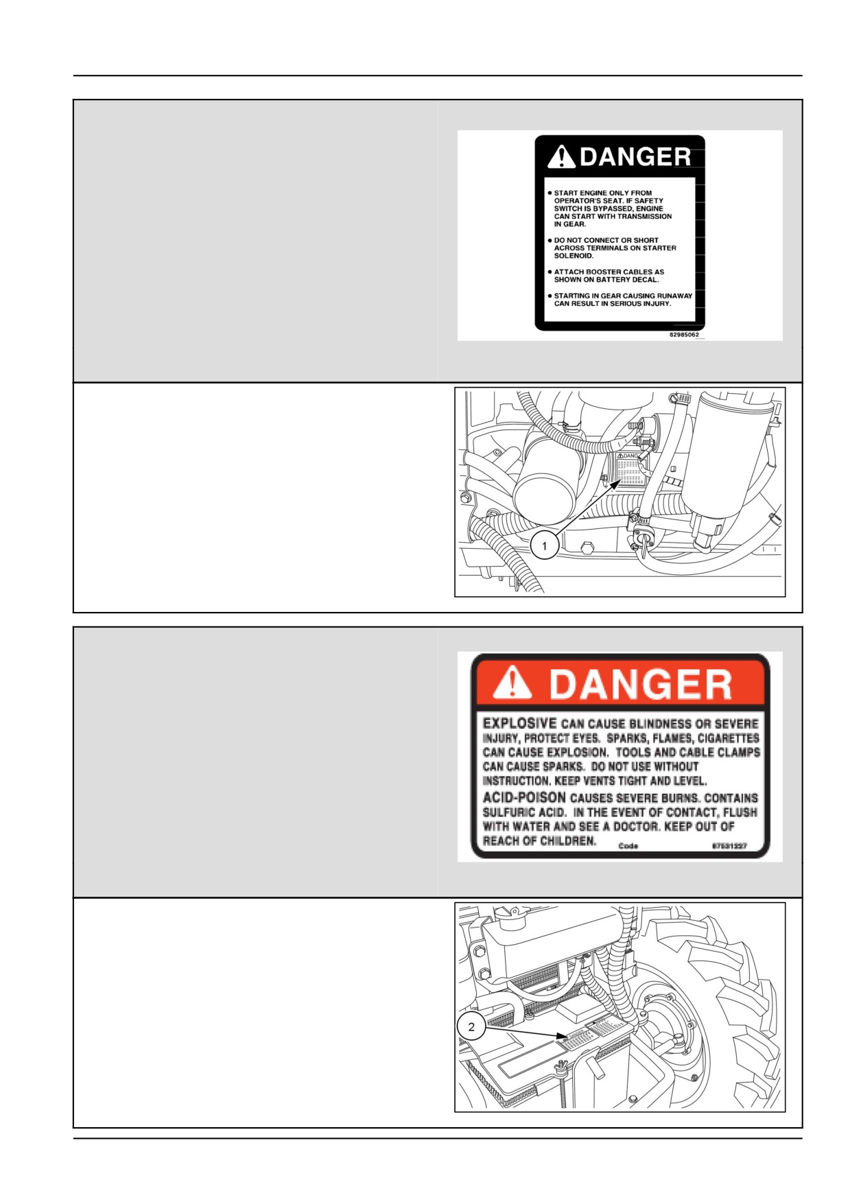
(1)
DANGER
•
Start engine only from operator’s seat. If safety
switch is bypassed, engine can start with
transmission in gear.
•
Do not connect or short across terminals on
starter solenoid.
• Attach booster cables as shown on battery decal.
•
Starting in gear causing runaway can result in
serious injury.
•
Failure to comply will result in death or serious
injury.
82985062N
2
Quantity: 1
English Part Number: 82985062
(1) Location: On starter motor.
GNIL14TR00568AA
3
(2)
DANGER
•
EXPLOSIVE
can cause blindness or sever injury, protect eyes,
sparks, flames, cigarettes can cause explosion.
Tools and cable clamps can cause sparks. Do not
use without instruction. Keep vents tight and level.
•
ACID-POISON
causes severe burns, contains sulfuric acid. In the
event of contact, flush with water and see a doctor.
Keep out of reach of children.
•
Failure to comply will result in death or serious
injury.
Quantity: 1
87531227N
4
English Part Number: 87531227
(2) Location: Top side of battery hold down bracket.
GNIL14TR00574AA
5
2-13
2 - SAFETY INFORMATION
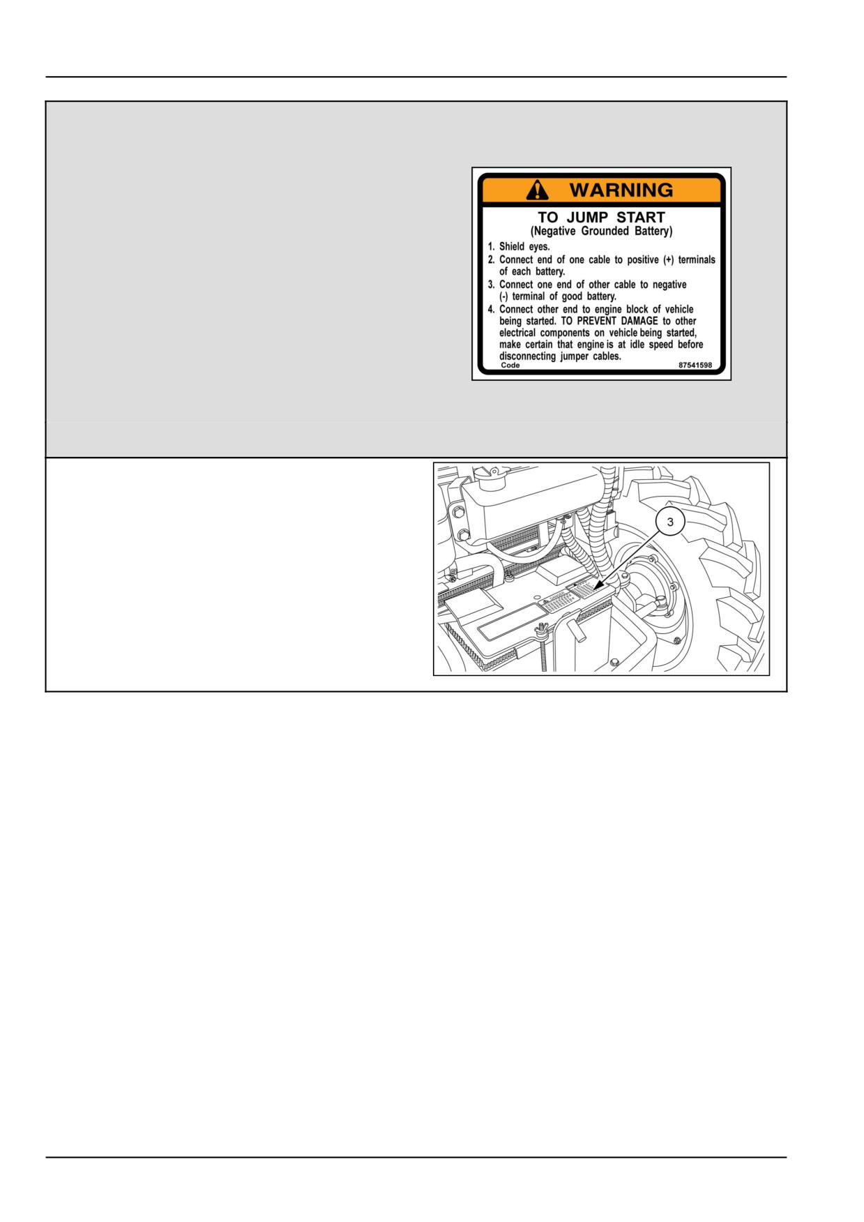
(3)
WARNING
TO JUMP START
(Negative Grounded Battery)
1.
Shield eyes
2. Connect end of one cable to positive (+) terminals
of each battery.
3.
Connect one end of other cable to negative (-)
terminal of good battery.
4.
Connect other end to engine block of vehicle
being started.
TO PREVENT DAMAGE to other electrical
components or vehicle being started, make
certain that engine is at idle speed before
disconnecting jumper cables.
87541598
6
5.
Failure to comply will result in death or serious
injury.
Quantity: 1
English Part Number: 87541598
(3) Location: Top side of battery hold down bracket.
GNIL14TR00574AA
7
2-14
2 - SAFETY INFORMATION
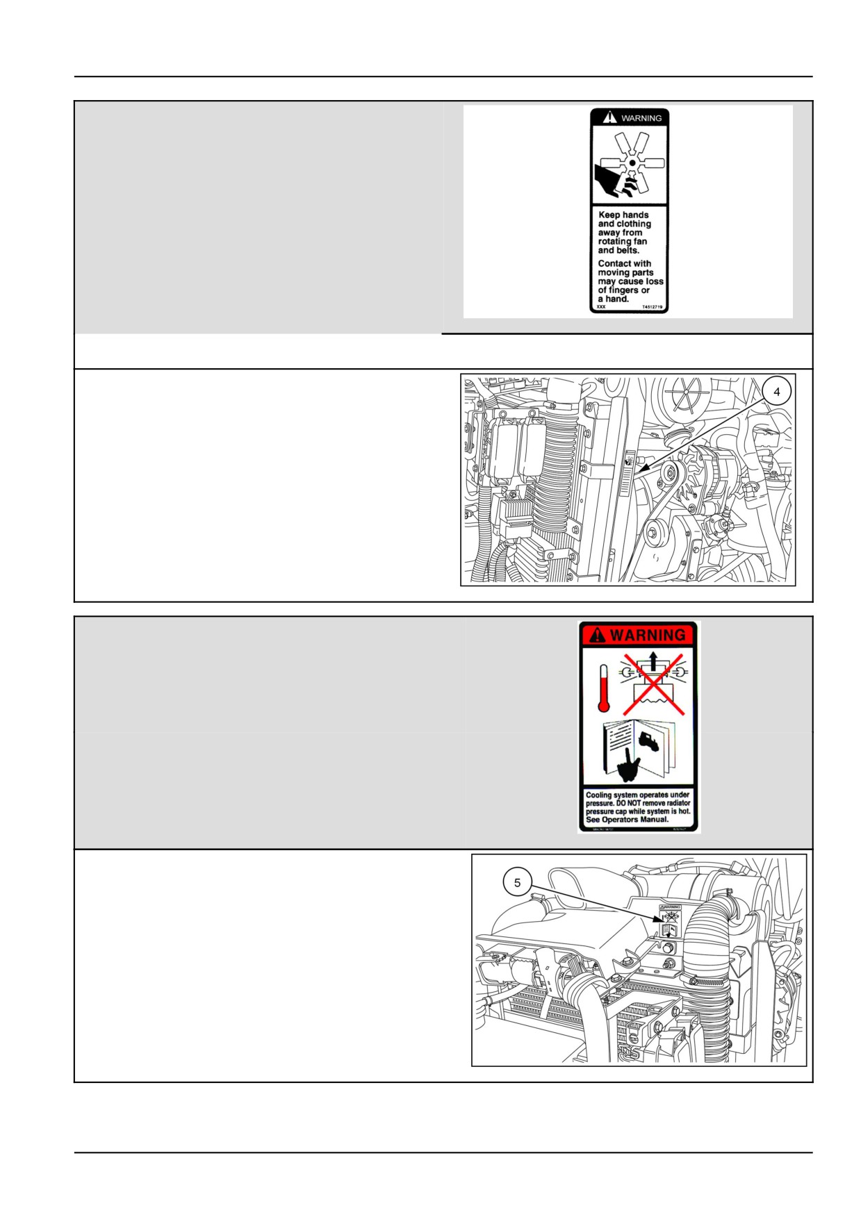
(4)
WARNING
• Keep hands and clothing away from the rotating
fan and belts.
•
Contact with moving parts may cause loss of
fingers or a hand.
•
Failure to comply will result in death or serious
injury.
86532907NN
8
Quantity: 2
English Part Number: 8652907
(4) Location: Both sides of the radiator.
GNIL14TR00577AA
9
(5)
WARNING
•
Cooling system operates under pressure. DO NOT
remove radiator pressure cap while system is hot.
See Operators Manual.
• Failure to comply will result in death or serious injury.
Quantity: 1
English Part Number: 82029421
82029421
10
(5) Location: On front of air cleaner
GNIL14TR00575AA
11
2-15
2 - SAFETY INFORMATION
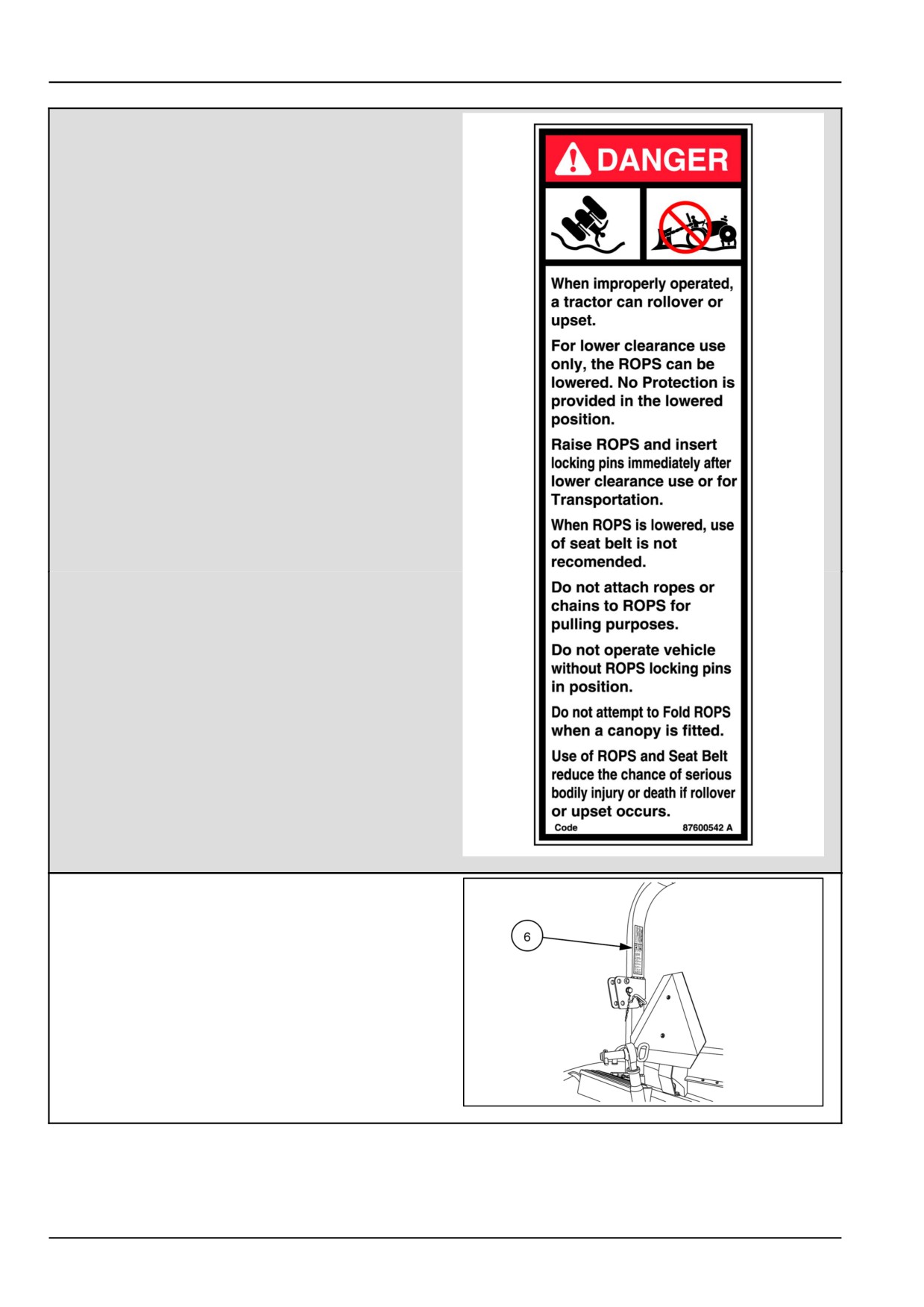
(6)
DANGER
• When improperly operated, a tractor can rollover
or upset.
•
For lower clearance use only, the ROPS can be
lowered. No protection is provided in the lowered
position.
• Raise ROPS and insert locking pins immediately
after lower clearance use or for transportation.
•
When ROPS is lowered, use of seat belt is not
recommended.
• Do not attach ropes or chains to ROPS for pulling
purposes.
• Do not operate vehicle without ROPS locking pins
in position.
•
Do not attempt to fold ROPS when a canopy is
fitted.
• Use of ROPS and seat belt reduce the chance of
serious bodily injury or death if rollover or upset
occurs.
•
Failure to comply will result in death or serious
injury..
Quantity: 1
English Part Number: 87600542
87600542N
12
(6) Location: Side of Roll Over Protective Structure
(ROPS)
GNIL14TR00570AA
13
2-16
2 - SAFETY INFORMATION
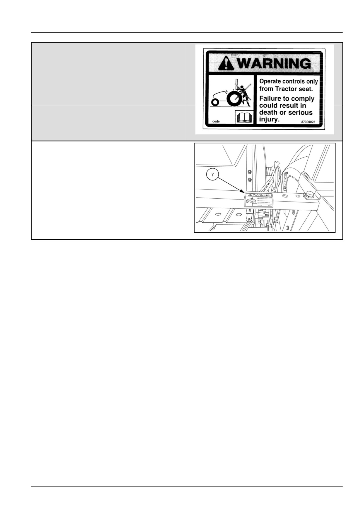
(7)
WARNING
•
Operate controls only from tractor seat.
Read Operator's Manual.
Failure to comply could result in death or serious
injury.
•
Failure to comply will result in death or serious
injury.
Quantity:1
English Part Number: 87300025
87300025N
14
(7) Location: Right - hand side of ROPS cross support. .
NHIL13CT00536AA
15
2-17
2 - SAFETY INFORMATION
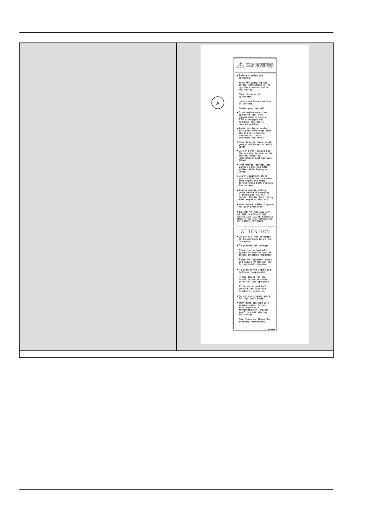
(8)
(A) WARNING
.Before starting and operating
.Know the operating and safety instructions in the
operators manual and on the tractor.
.Clear the area of bystanders.
.Locate and know the operation of controls.
.Fasten your seat belt.
.Start engine only from operators seat with
transmission in neutral, PTO disengaged and
hydraulic controls in the lowered position.
.Avoid accidental contact with gear shift lever while
the engine is running. Unexpected tractor movement
can result.
.Slow down on turns, rough ground and slopes to
avoid upsets.
.Do not permit anyone but the operator to ride on the
tractor, unless an instructional seat has been fitted.
.Lock brakes together, use warning lights and SMV
emblem while driving on roads.
.Lower equipment, place gear shift levers in neutral,
stop engine an apply parking brake before leaving
tractor seat.
.Always engage parking brake before dismounting.
Transmission will not prevent tractor from rolling
when engine is shut off.
.Keep safety shields in place for your protection.
.FAILURE TO FOLLOW ANY OF THE INSTRUCTIONS
ABOVE CAN CAUSE SERIOUS INJURY TO THE
OPERATOR OR OTHER PERSONS.
82030429N
16
2-18
2 - SAFETY INFORMATION
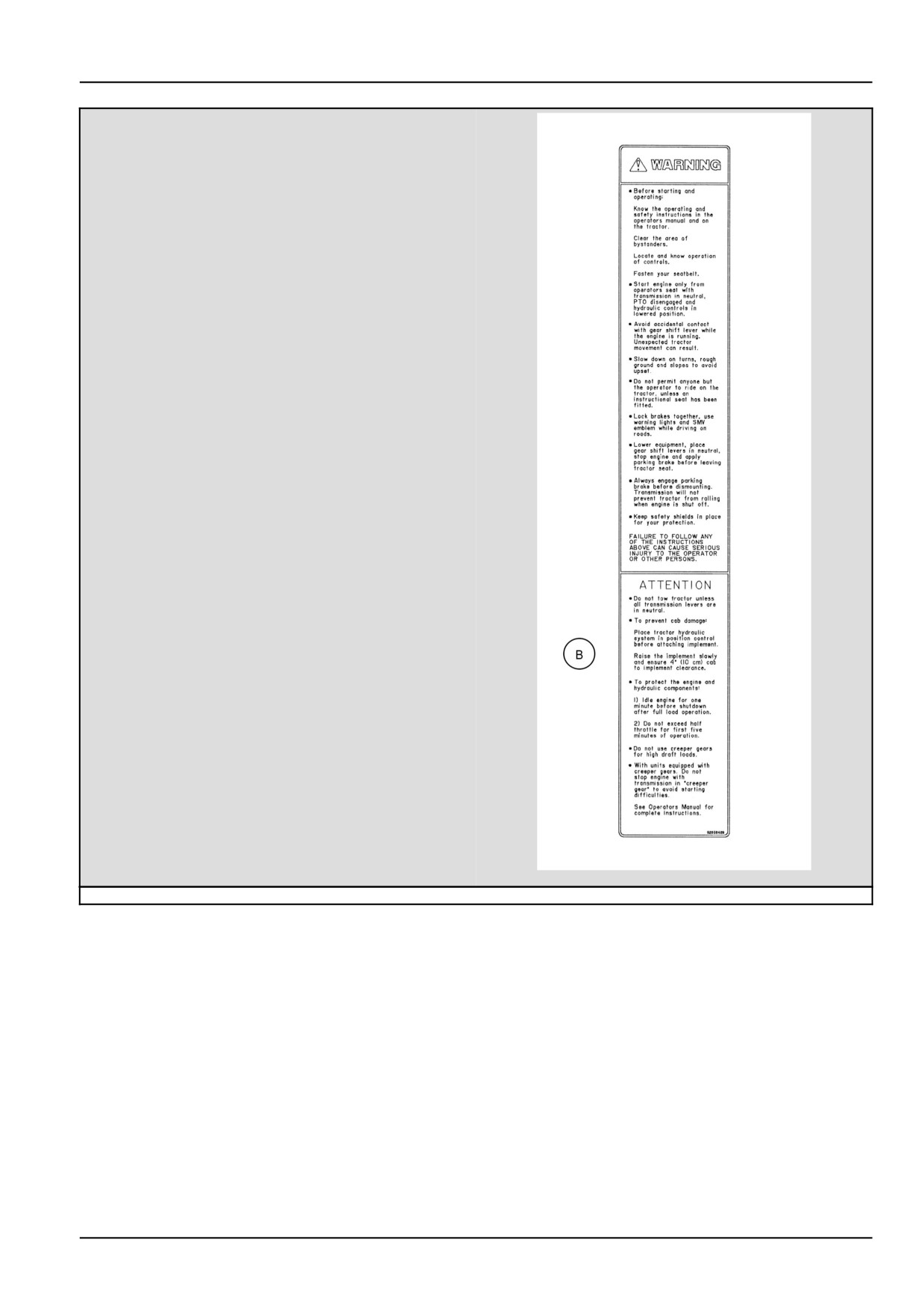
(B) ATTENTION:
• Do not tow tractor unless all transmission levers
are in neutral.
•
To prevent cab damage
• Place tractor hydraulic system in position control
before attaching implement.
• Raise the implement slowly and ensure 4” (10cm)
cab to implement clearance.
• To protect the engine and hydraulic components:
•
1) Idle engine for one minute before shutdown
after full load operation.
•
2) Do not exceed half throttle for first five minutes
of operation.
•
Do not use creeper gears for high draft loads.
•
With units equipped with creeper gears. Do not
stop engine with transmission in “creeper gear” to
avoid starting difficulties.
• See Operators Manual for complete instructions.
Quantity: 1
English Part Number: 82030429
82030429N
17
2-19
2 - SAFETY INFORMATION
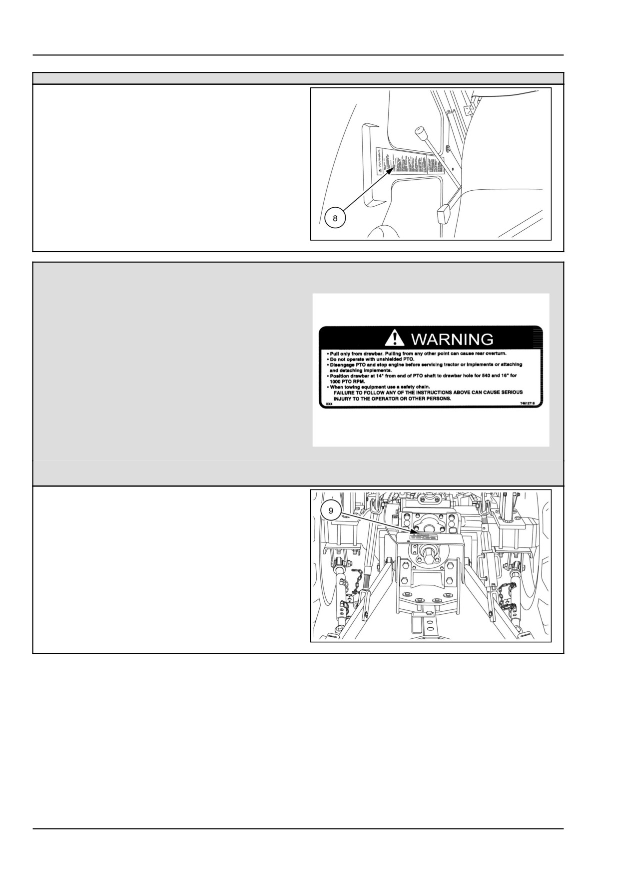
(8) Location: Inside of the right-hand fender.
GNIL14TR00573AA
18
(9)
WARNING
•
Pull only from drawbar. Pulling from any other
point can cause rear overturn.
•
Do not operate with unshielded PTO.
• Disengage PTO and stop engine before servicing
tractor or implements or attaching or detaching
implements.
• Position drawbar at 14” from end of PTO shaft to
drawbar hole for 540 and 16” for 1000 PTO RPM.
•
When towing use a safety chain.
• FAILURE TO FOLLOW ANY OF THE INSTRUCTIONS
ABOVE CAN CAUSE SERIOUS INJURY TO THE
86532904N
19
OPERATOR OR OTHER PERSONS.
Quantity: 1
English Part Number: 86532904
(9) Location: On top of the rear PTO guard.
GNIL14TR00579AA
20
2-20
2 - SAFETY INFORMATION
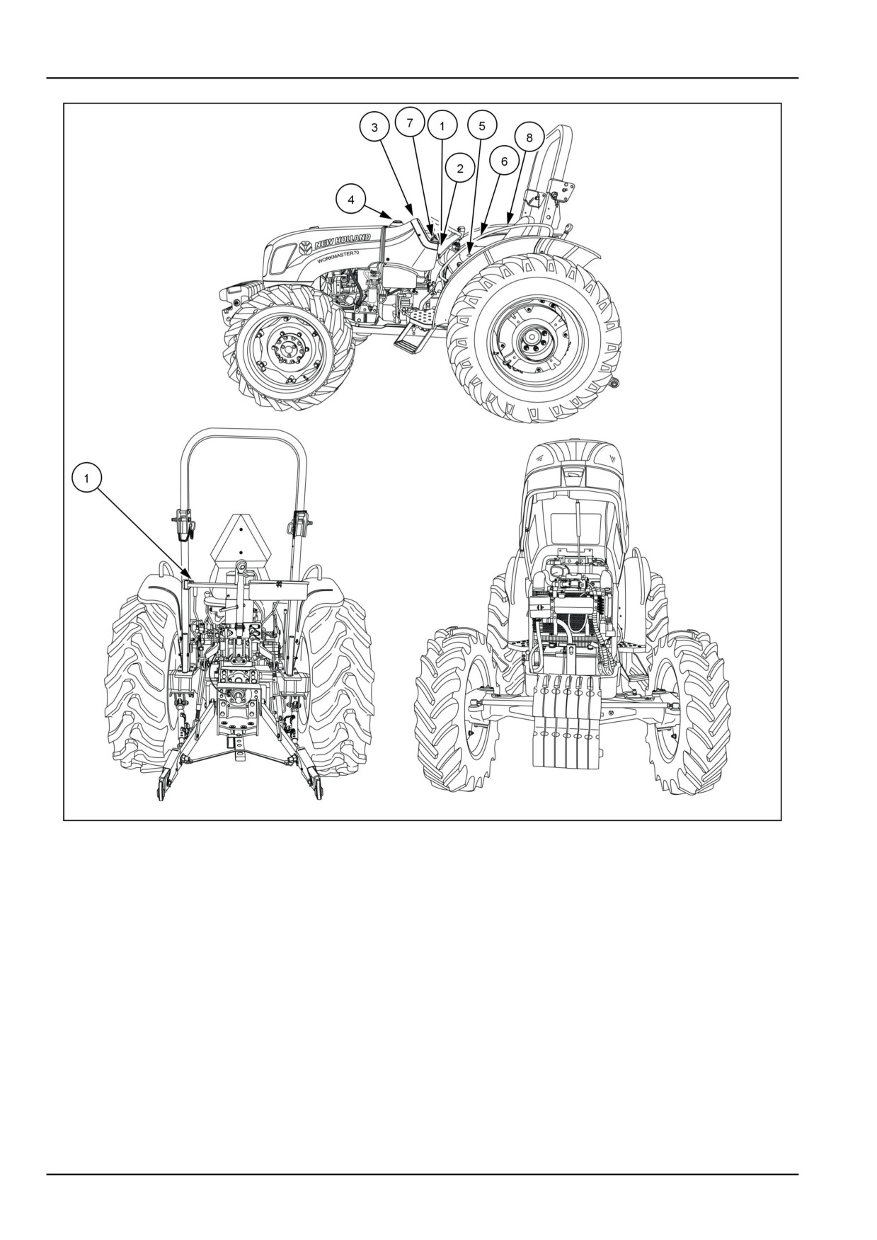
Instructional signs
The following instructional signs have been placed on your tractor in the area indicated. They are intended to instruct
you and those working with you. Please take this manual and walk around your tractor to note the content and location
of these signs. Review the signs and operating instructions detailed in this manual with the tractor operators. Keep
the signs clean and legible. If they become damaged or illegible, obtain replacements from your authorized NEW
HOLLAND dealer.
Keep instructional signs clean and legible. Clean instructional signs with a soft cloth, water, and a gentle detergent.
Do not use solvent, gasoline, or other harsh chemicals. Solvents, gasoline, and other harsh chemicals may damage
or remove instructional signs.
2-21
2 - SAFETY INFORMATION
GNIL14TR00551HA
1
2-22
2 - SAFETY INFORMATION
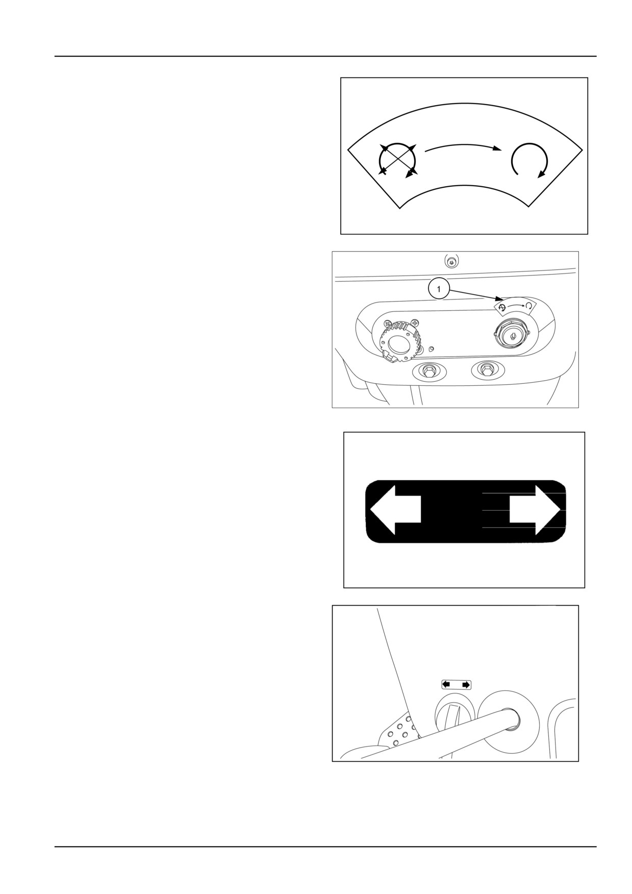
(1)
Key switch
• Part number 82833395
Location: Above the key switch
GNIL14TR00563AA
2
GNIL14TR00576AA
3
(2)
Turn signal
• Part number 87316799
Location: Above turn signal switch
87316799N
4
NHIL13CT00531AA
5
2-23
2 - SAFETY INFORMATION
(3)
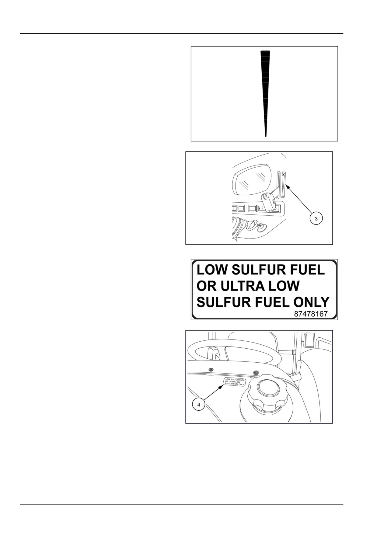
Hand throttle
• Part number 81863547
Location: Top right-hand side of dash
81863547N
6
GNIL14TR00571AA
7
(4)
Low sulfur fuel
• Part number 87478167
Location: Beside fuel cap
87478167
8
NHIL13CT00533AA
9
2-24
2 - SAFETY INFORMATION
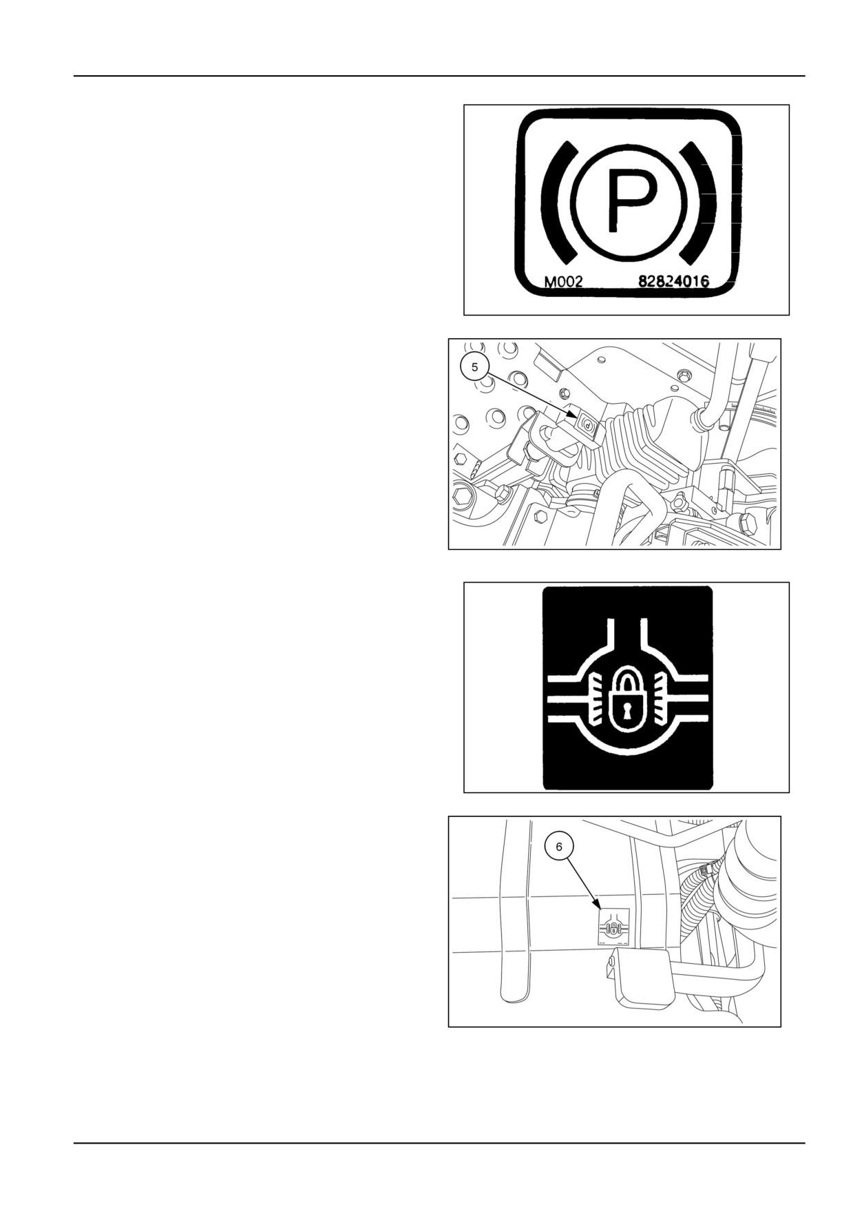
(5)
Park brake
• Part number 82016114
Location: Below operator’s seat on right-hand side on top
of park brake knob.
82016114N
10
GNIL14TR00572AA
11
(6)
Differential lock
• Part number 86532901
Location: Right-hand side of operator’s platform.
86532901N
12
NHIL13CT00538AA
13
2-25
2 - SAFETY INFORMATION
(7)
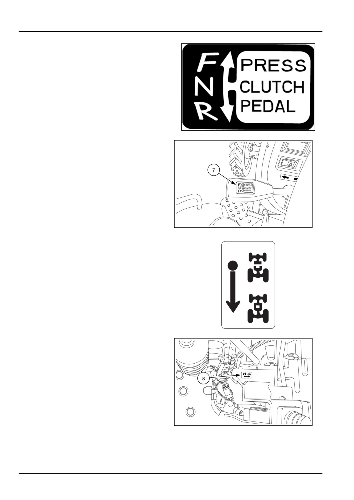
Shuttle shift
• Part number 84135594
Location: On shuttle shift lever knob
84135594
14
NHIL13CT00546AA
15
(8)
FWD
• Part number 5143545
Location: Lower left-hand side of the operator’s platform.
5143545
16
GNIL14TR00569AA
17
2-26
2 - SAFETY INFORMATION
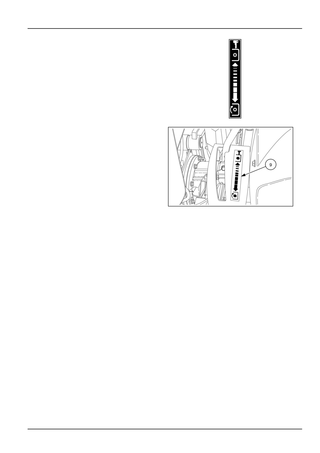
(9)
PTO control
• Part number 86538220
Location: Left-hand side of operator’s platform on Power
Take-Off (PTO) quadrant
84259170
18
NHIL13CT00534AA
19
2-27
2 - SAFETY INFORMATION
2-28
3 - CONTROLS AND INSTRUMENTS
3 - CONTROLS AND INSTRUMENTS###_3_###
ACCESS TO OPERATOR'S PLATFORM
Before operating
WARNING
Improper operation or service of this machine
can result in an accident.
Read and understand the SAFETY INFORMA-
TION Section before you operate or service
the machine.
Failure to comply could result in death or se-
rious injury.
W0266A
Read this section thoroughly. The controls and instru-
ments section details the location and operation of the var-
ious instruments, switches, and controls on your tractor.
Even if you operate other tractors, you should thoroughly
read this section of the manual and ensure that you are
familiar with the location and function of all the features of
the tractor.
Do not start the engine, or attempt to drive or operate the
tractor until you are fully familiar with all the controls. It
is too late to learn once the tractor is moving. If you have
any questions about any aspect of operation of the tractor,
consult your authorized dealer.
Pay particular attention to the recommendations for run-
ning-in to ensure that your tractor will give the long and
dependable service for which it was designed.
OPERATOR'S SEAT
Operator's seat
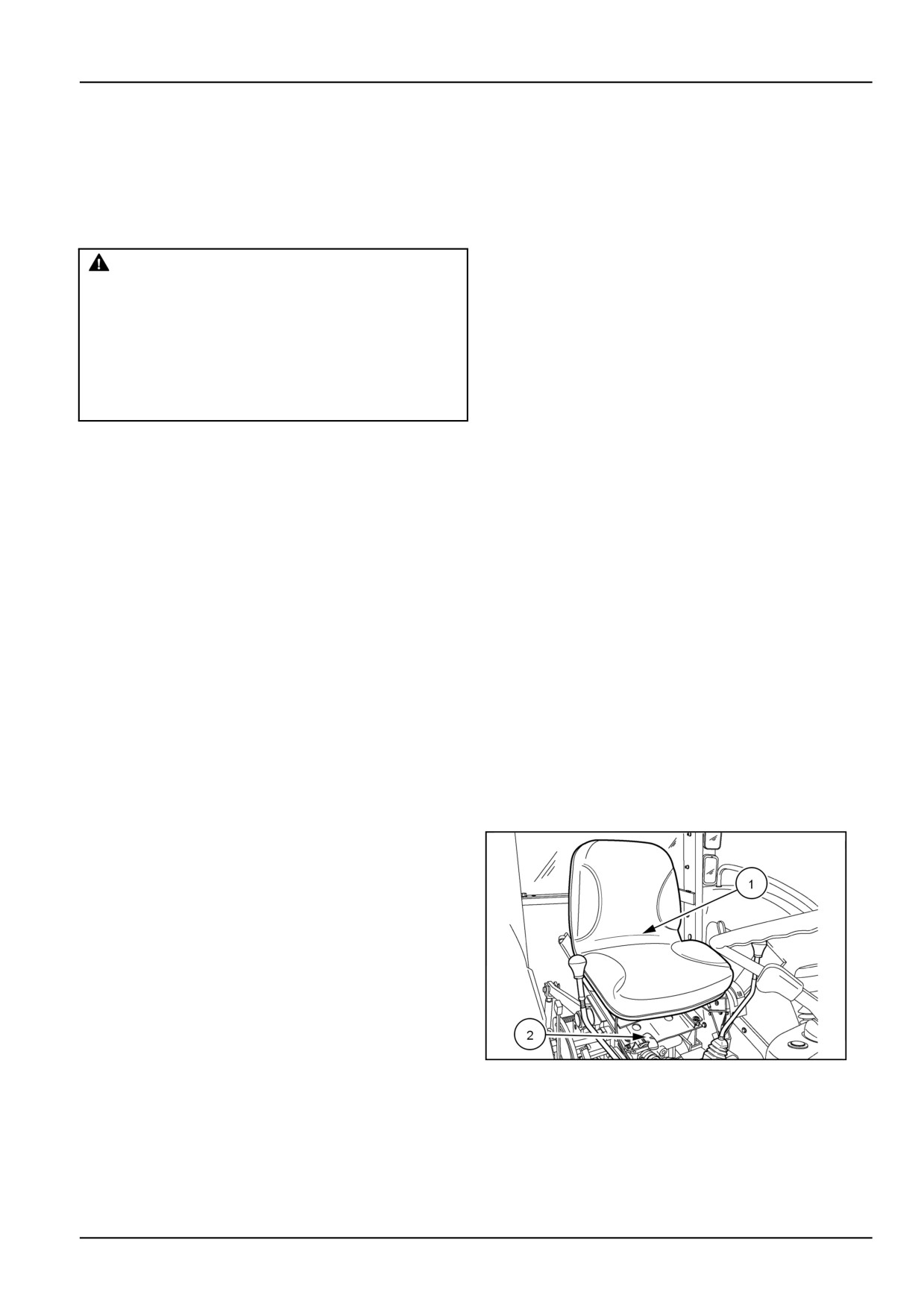
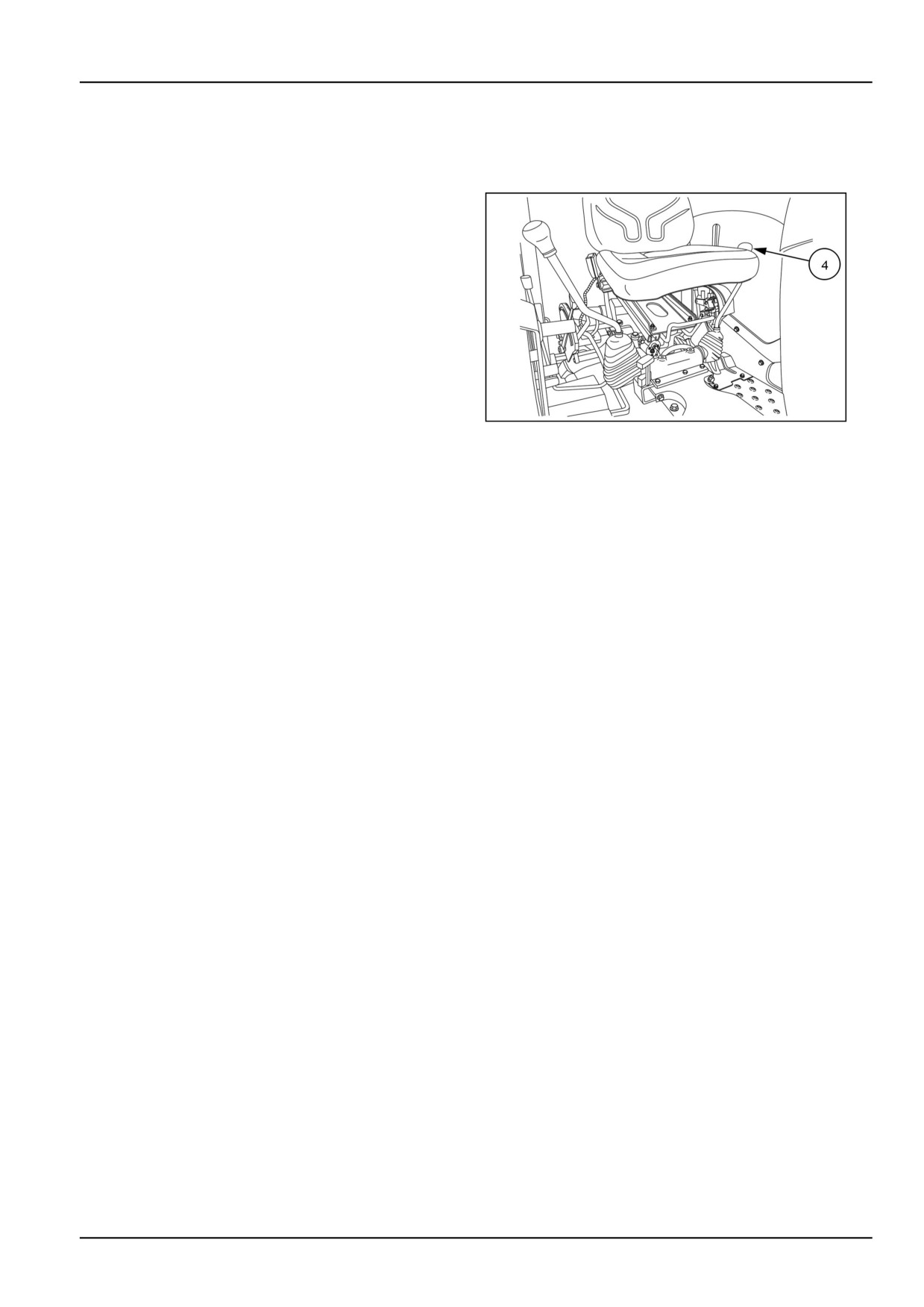
Your tractor is equipped with an adjustable seat, (1). Be-
fore operating the tractor, it is important to adjust the seat
to the most comfortable position. See the following text
and illustrations for details.
Operator's seat adjustment
To move the seat forward and rearward, raise the lever,
(2), and position the seat to a comfortable position.
Do not start the engine or attempt to drive or operate the
tractor until you are fully familiar with all the controls. It
is too late to learn once the tractor is moving. If you have
any questions about any aspect of operation of the tractor,
consult your authorized dealer.
NHIL13CT00714AA
1
3-1
3 - CONTROLS AND INSTRUMENTS
Weight adjustment
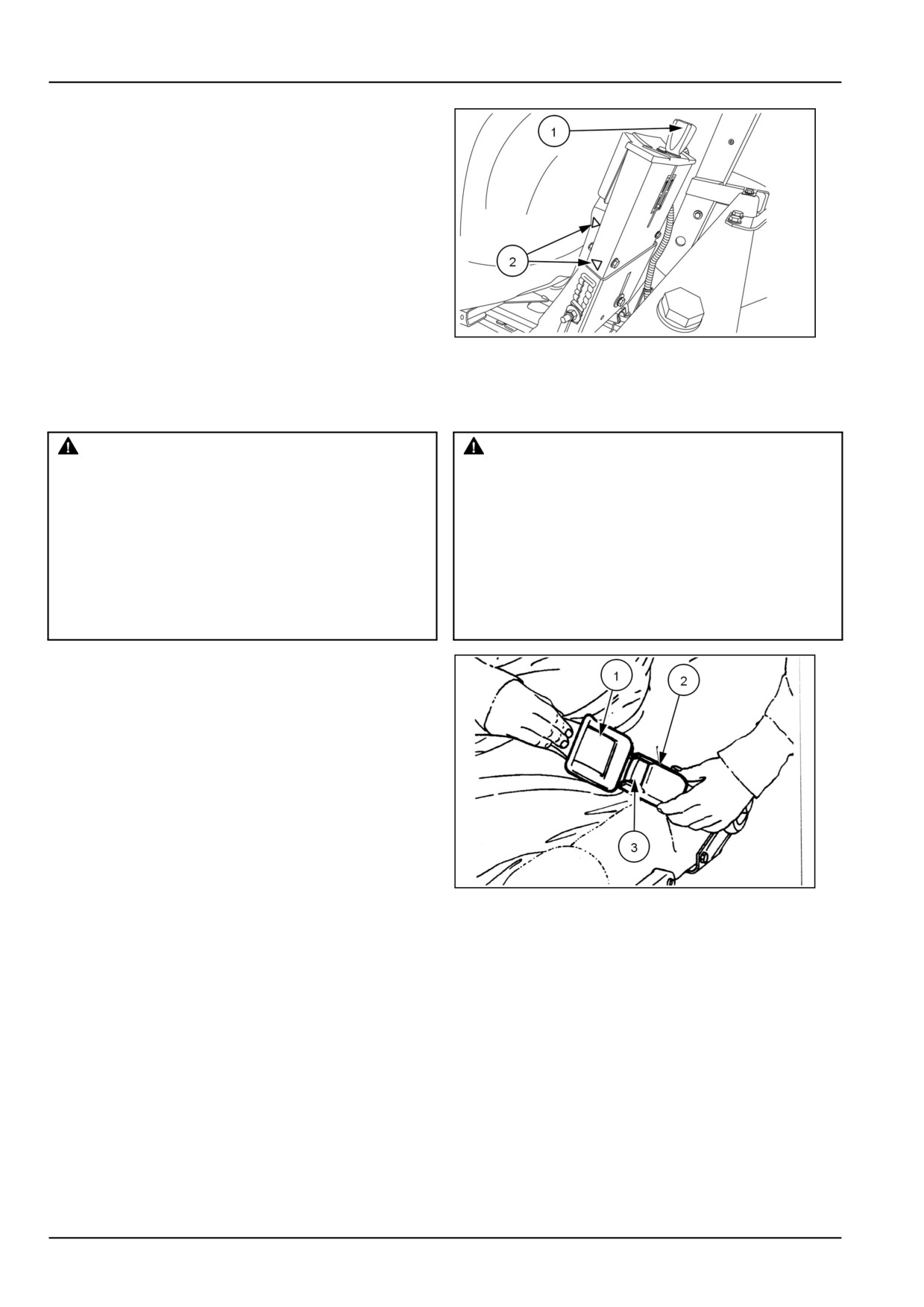
Sit on the operator’s seat. Adjust the weight adjustment
knob (1) and match the two arrows (2) for optimum com-
fort. This is also necessary for the proper functioning of
the operator alert system.
GNIL14TR00590AA
2
Seat belt
WARNING
WARNING
Equipment failure could cause accident or in-
Crushing hazard!
jury!
Always wear the seat belt when operating the
Always fasten the seat belt securely before
machine with the Roll Over Protective Struc-
you operate the machine. Inspect seat belt
ture (ROPS) in the upright position. If the
parts for wear and damage. Replace any and
ROPS is in the folded position, the seat belt
all worn or damaged parts of the seat belt prior
should not be used. Raise the ROPS and wear
to operation.
the seat belt as soon as conditions allow.
Failure to comply could result in death or se-
Failure to comply could result in death or se-
rious injury.
rious injury.
W0046C
W0462A
To fasten the seat belt, pull the belt from the retractor and
push the tongue (1) into the buckle end (2) until a ‘click’ in-
dicates that the tongue is properly engaged. Press the red
release button (3) on the buckle and remove the tongue
from the buckle.
Cleaning the seat and seat belt
The seat belt may be sponged with clean, soapy water.
Do not use solvents, bleach or dye on the belt as these
chemicals will weaken the webbing.
Replace the seat belt when the seat beltshows signs of
fraying, damage or general wear.
Do not use solvents to clean the seat. Use only warm
20108779
1
water with a little detergent added or a proprietary brand
of automotive upholstery cleaner. Avoid wetting the seat
more than is absolutely necessary.
3-2
3 - CONTROLS AND INSTRUMENTS
FORWARD CONTROLS
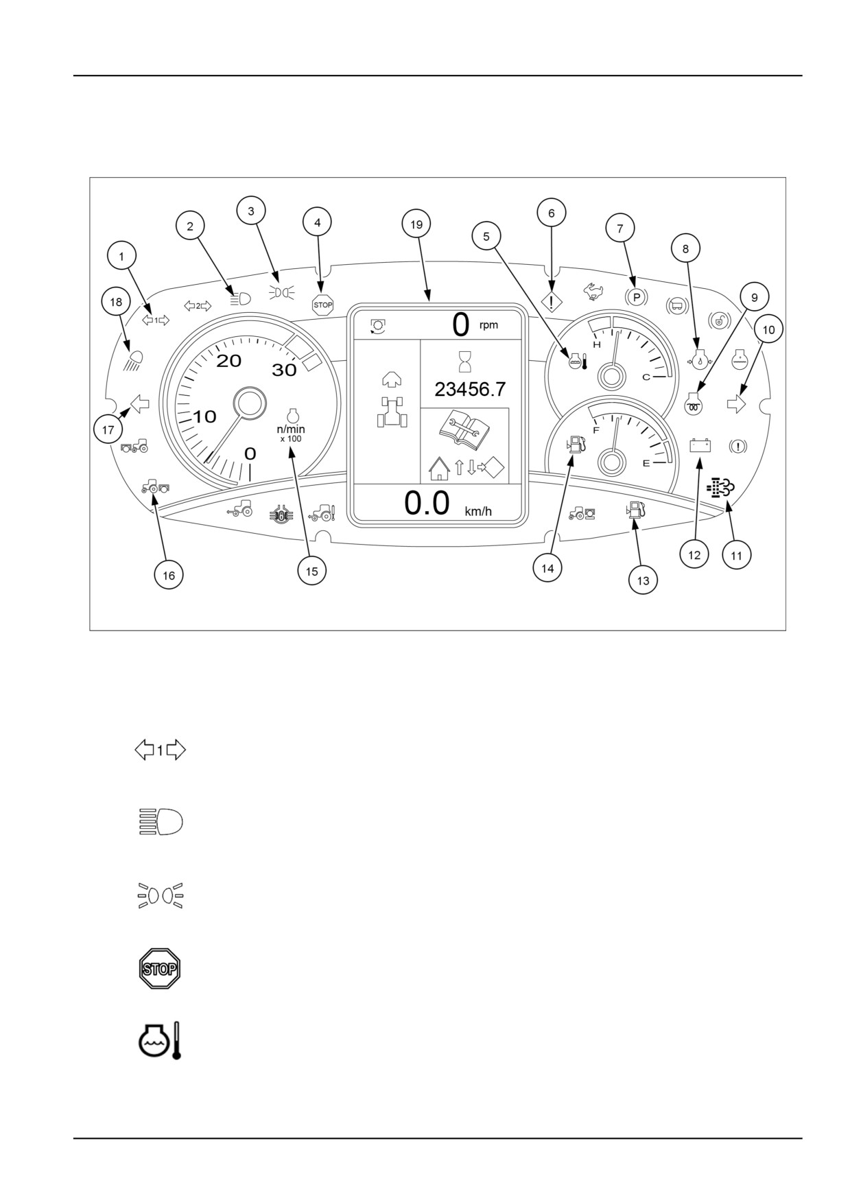
Instrument cluster - Localization overview
GNIL14TR00509FA
1
The indicator lights on the control panel inform you of the operational condition of the machine. Some of these indicate
faults arising during operation. An indicator light coming on may be followed by a continuous or intermittent buzzer.
Depending on the severity of the trouble, the alarm will sound.
Trailer direction indicator light (green)
1
This indicator light flashes together with the tractor/trailer direction indicators, if the first
trailer is connected
High beam headlights (blue)
2
This indicator light will illuminate when the tractor headlights are switched to high beam.
Marker lights (green)
3
This indicator light is illuminated when the tractor lights are turned on.
Stop warning light (red)
4
If the red “Stop” warning light illuminates, switch off the tractor immediately and look for the
cause. A warning symbol will appear on the display confirming the location of the fault.
Engine coolant temperature gauge
5
This instrument indicates the temperature of the engine coolant.
3-3
3 - CONTROLS AND INSTRUMENTS
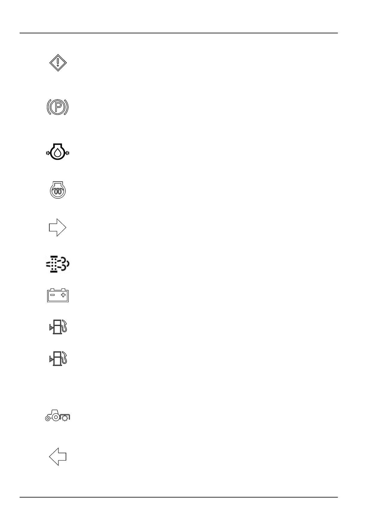
Indicator lamp (amber)
This indicator light illuminates and the display shows a warning symbol . The light blinks for 4
6
seconds, after which the symbol on the display disappears and the indicator light stays on
steady. To display the fault, you need to go to the menu 6 . Stop the tractor and investigate
the cause of the trouble.
Parking brake warning light (red)
This indicator illumininates when the key start switch is turned ON with the parking brake
7
applied. If the key-start switch is turned OFF and the parking brake is not applied, or the
operator leaves the seat without applying the parking brake, a warning buzzer will sound for
approximately 10 seconds or until the parking brake has been applied.
Engine oil pressure warning light (red)
This indicator light together with the red (5). ”Stop” indicator light indicates the e ngine oil
8
pressure is too low. Stop the engine and investigate the cause.
NOTE: With low engine oil pressure, this warning light illuminates when the start switch is in
the contact position (supply to accessories - ignition).
Cold start device (amber)
9
The indicator lights up when the glow plugs are turned on by the key switch.
Right-hand direction indicator (green)
This indicator light flashes at the same time as the tractor's right-hand direction indicator. With
10
the tractor running, if the turn signal is not switched off within 20 seconds, an intermittent alarm
comes on. This audible warning comes on if the direction indicator is not turned off within five
minutes with the tractor stationary.
Warning light of the Diesel Particulate Filter (DPF) (green)
11
For more details, see the chapter on regeneration of the particulate filter.
Alternator charging warning light (red)
12
A steady light indicates that the alternator is not charging the battery.
Fuel reserve (amber)
13
The light comes on when the tractor needs to be refueled.
Fuel level gauge
14
This instrument shows the fuel level in the tank.
Revolution counter
15
Indicates the engine — RPM . Each subdivision of the graduated scale represents 100 RPM
Rear Power Take-Off (PTO) indicator light (yellow)
Lights up when the engine is running and the rear Power Take-Off (PTO) is engaged.
16
The indicator light will start to flash if the engine speed exceeds the maximum allowable
engine speed for the PTO..
Left-hand direction indicator (green)
This indicator light flashes at the same time as the tractor's left-hand direction indicator. With
17
the tractor running, if the turn signal is not switched off within 20 seconds, an intermittent alarm
comes on. This audible warning comes on if the direction indicator is not turned off within five
minutes with the tractor stationary.
3-4
3 - CONTROLS AND INSTRUMENTS
Work lights (amber)
18
This indicator light illuminates when the work lights are switched on.
Information display
19
The display shows information on the operational condition of the machine and highlights any
trouble in the form of symbols or error codes.
3-5
3 - CONTROLS AND INSTRUMENTS
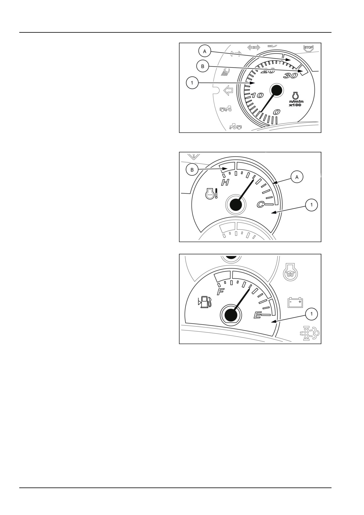
Tachometer
The tachometer (1) indicates the engine speed in Revolu-
tions Per Minute (RPM). Each division on the scale repre-
sents 100 RPM. Therefore, with the needle indicating 20,
the engine is running at 2000 RPM.
Engine speed
NOTICE: Never run the engine continuously or for a long
periods of time at speeds between 2500 - 3000 RPM (yel-
low area (A) on the tachometer) to avoid damage to the
engine. Never exceed 3000 RPM (red area (B) on the
tachometer). For appropriate use, always operate the en-
DCUTLBRNE003S3A
2
gine under 2300 RPM.
Engine coolant temperature gauge
The temperature display (1) indicates the temperature of
the engine coolant.
• green area (A) = normal temperature
• red area (B) = temperature too high
If the engine overheats, slow the engine to idling speed
(without stopping the engine) and, if the light stays on,
have the cooling system checked.
DCUTLBRNE004S3A
3
Fuel level gauge
This instrument (1) indicates the level of diesel in the tank
and only works when the ignition key is turned to ON.
DCUTLBRNE005S3A
4
3-6
3 - CONTROLS AND INSTRUMENTS
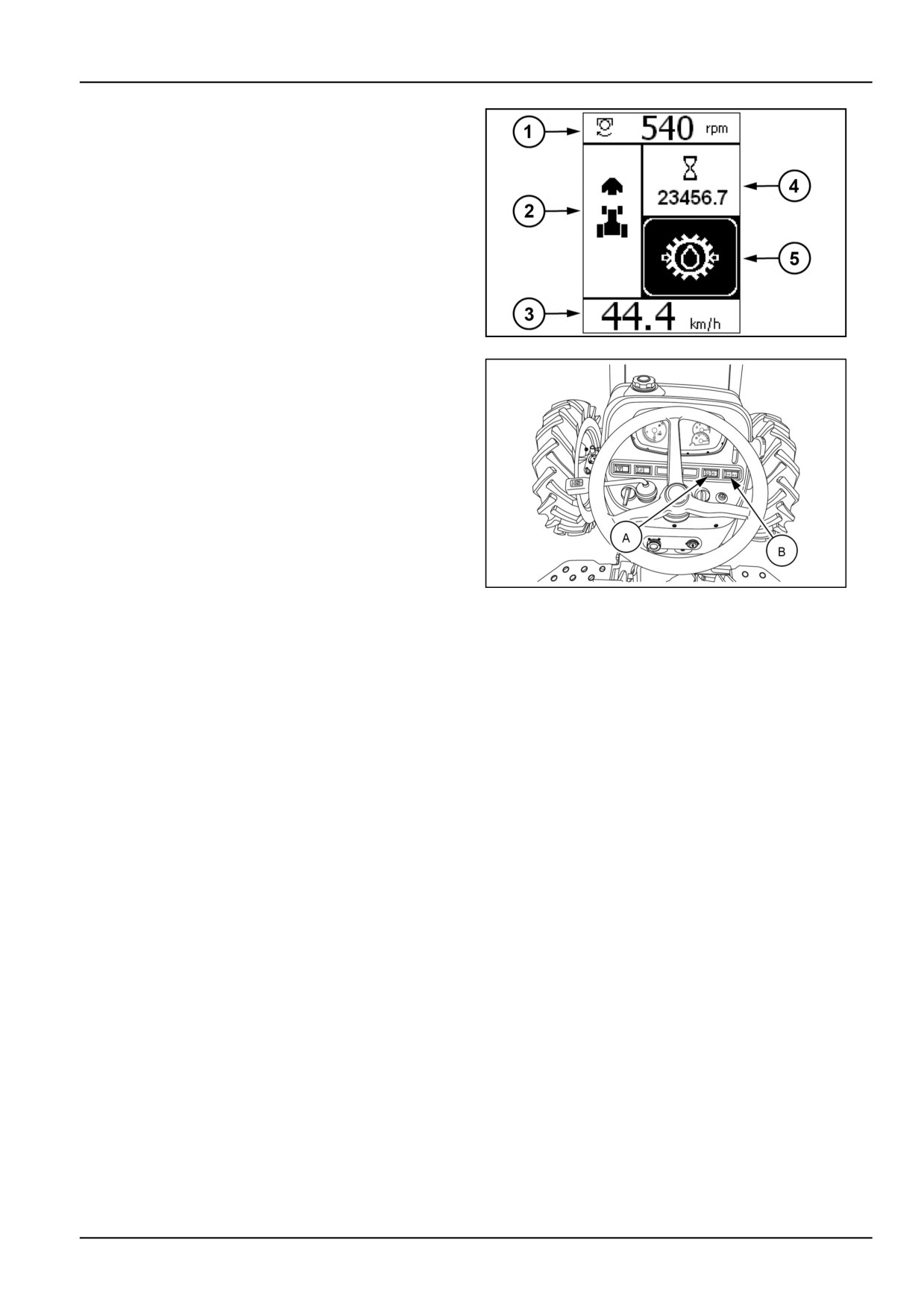
Central display
The central Liquid Crystal Display (LCD) provides the op-
erator with a range of information
1. Front or rear Power Take-Off (PTO) speed
Front or rear lift position
Slip
Data displayed by pressing and releasing the button
ENTER, see figure 6
2. Tractor direction
3. Speed of the vehicle in Km/h or MPH
DCAPLT5NE005S3F
5
4. Tractor hour meter
5. Kilometers or miles travelled
Area worked
Area worked per hour
Battery voltage
Data displayed by pressing the arrow buttons up or
down (B), see 6
When necessary, warning and error messages
Programming menu (see specific chapter)
GNIL14TR00512AA
6
3-7
3 - CONTROLS AND INSTRUMENTS
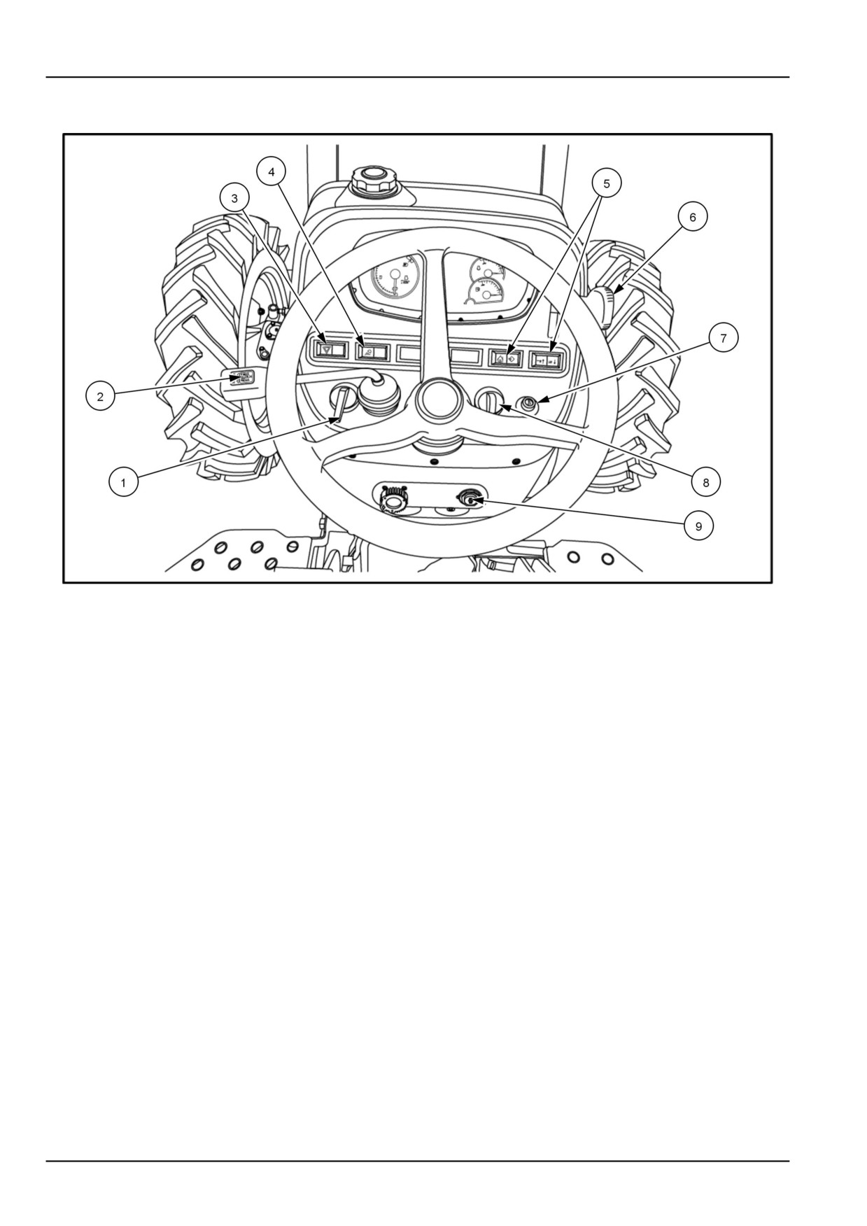
Hand controls and switches
GNIL14TR00512AA
1
Turn signal switch
Hazard switch
The turn signal switch (1) activates the turn signals. Move
The hazard switch (3) activates the hazard flasher lights.
the turn signal switch to the right to operate the right-hand
Use the hazard flasher lights when traveling on public
turn indicator light and to the left to operate the left-hand
roads, day or night.
turn indicator light.
Head light switch
NOTE: The turn signal will operate only when the key
switch is turned on.
The head light switch (4) consists of four positions, (see
head light switch positions, see 2 ).
Shuttle shift lever
The shuttle shift lever (2) is used to change the direction
of travel, between forward and reverse.
Central display navigation buttons
Navigate through the menus of the central Liquid Crystal
Display (LCD) with the rocker switches (5).
(A) and (B) see the image in the previous page.
Hand throttle lever
Horn Button
The hand throttle lever (6) should be used during field
Press the horn button (7) to activate the horn.
operation of the tractor.
Push the lever forward to increase the engine speed and
rearward to reduce the engine speed.
3-8

3 - CONTROLS AND INSTRUMENTS
Head Light Switch Positions
The head light switch (8), see 1 consists of four positions,
Position (1)
- Off
Position (2)
- Parking lights on.
Position (3)
- Head lamp low beam.
Position (4)
- Head lamp high beam.
20108778
2
Key start/stop switch
The key switch (9) activates electrical equipment, lights,
gauges, and starter motor.
3-9
3 - CONTROLS AND INSTRUMENTS
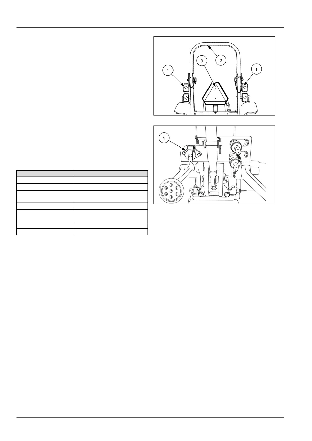
Hazard Warning Light Switch
The hazard warning lights switch (3) ( 1) activates the haz-
ard flashing warning lights (1) located on each side of the
Roll Over Protective Structure (ROPS) (2).
The hazard flashing warning lights can be activated with
the key switch in any position. For your protection, use the
flasher warning lights and the Slow Moving Vehicle (SMV)
emblem (3) when travelling on public roads, day or night.
76099309N
3
Trailer electrical socket
A standard 7-pin trailer socket (1) is a standard equipment
and the 7-pin trailer socket is mounted to the left-hand side
of ROPS cross brace.
The trailer socket pin connections (see insert) are as fol-
lows:
Pin No.
Circuit
1
Ground (White)
2
Side Marker Lights
Left-hand flashing and turn
3
indicator
4
Stop Lamp
76099308N
4
Right-hand flashing and turn
5
indicator
6
Tail Lamp
7
NA
3-10
3 - CONTROLS AND INSTRUMENTS
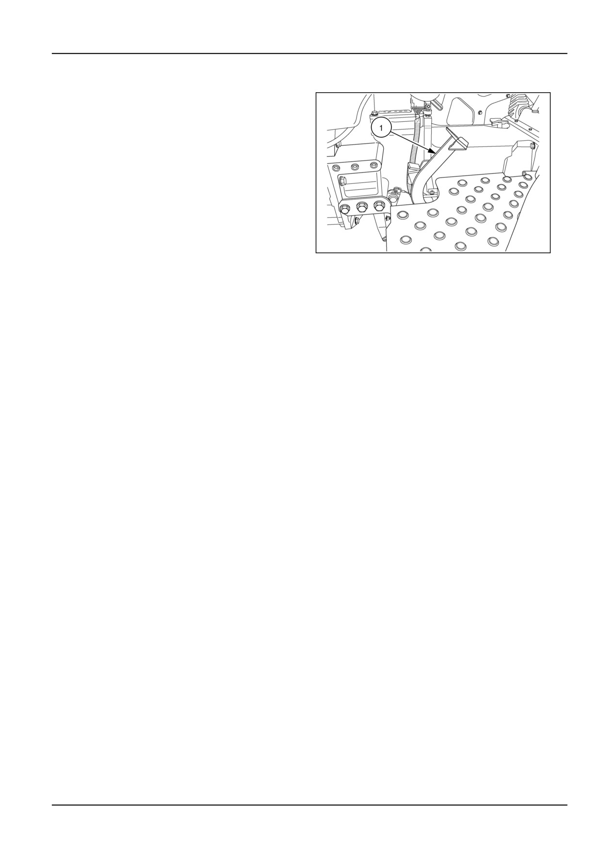
Clutch pedal
When the clutch pedal (1) is depressed, the drive between
the engine and the transmission will be disengaged. Use
the clutch pedal to transfer engine power smoothly to the
rear wheels when moving off from a stationary position.
NOTICE: Always depress the clutch pedal before engag-
ing or disengaging a gear.
NOTICE: Do not use the clutch pedal as a footrest when
driving the tractor. Such action will lead to clutch slippage
and premature clutch failure.
86090118
1
3-11
3 - CONTROLS AND INSTRUMENTS
Brake pedals - Control identification
WARNING
Loss of control hazard!
One-sided brake force exists if you do not use
the brake pedal latch, and if you do not de-
press the left and right pedals at the same
time. ALWAYS use the brake pedal latch when
traveling at transport speeds and/or when a
trailer with hydraulic or air-applied brakes is
attached to the machine.
Failure to comply could result in death or se-
rious injury.
W0375A
86096194N
1
Brake pedals
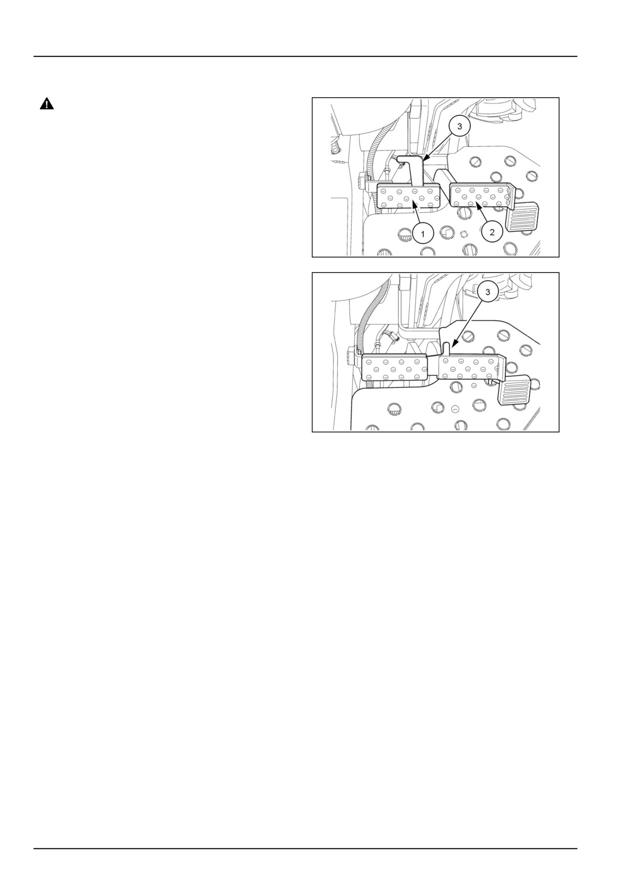
The left-hand and right-hand foot brakes (1) & (2), may
be operated independently to assist turning in confined
spaces or locked together for normal stopping. When op-
erating in the field the brake pedals may be unlocked.
However, due to the proximity of the pedals to one an-
other, it is still possible to apply both brakes together when
required. To lock the pedals together, pivot the latch (3)
into the right-hand brake pedal (2) slot.
NOTE: The brake latch is used to lock both brake pedals
together. Brake pedals must be locked together for road
travel. This will insure uniform brake application and max-
imum stopping ability.
86096195N
2
3-12

3 - CONTROLS AND INSTRUMENTS
Transmission - Control identification
Transmission shuttle lever
The shuttle shift lever (1) is used to engage the transmis-
sion into forward or reverse. You must depress the clutch
pedal in order to shift the transmission . Move the lever
forward to enable the tractor to travel forward and rear-
ward to enable the tractor to travel in reverse.. The shuttle
lever must be in the neutral (middle) position to activate
the safety start system and allow the engine to start.
GNIL14TR00512AA
1
3-13
3 - CONTROLS AND INSTRUMENTS
Foot throttle control - Control identification
The foot throttle pedal (1) may be used independently of
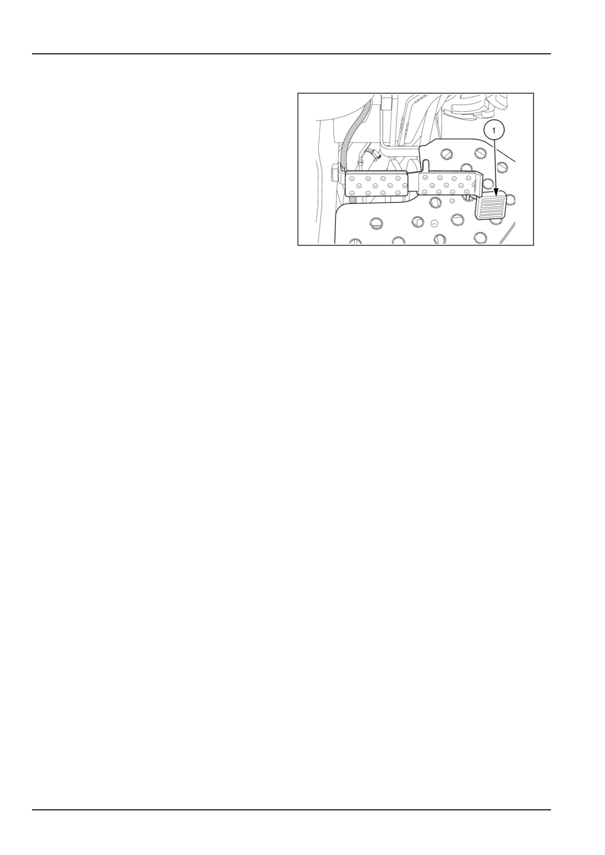
the hand throttle lever to control the speed of the tractor.
Use the foot throttle pedal when you drive on the main
road or on the highway.
86096195N
1
3-14
3 - CONTROLS AND INSTRUMENTS
LEFT-HAND SIDE CONTROLS
Transmission - Control identification
Transmission range lever (Hi-Low)
The Hi-Low range lever (4) is used to select the high or
low range, which gives the operator double the number
available speeds. Always depress the clutch pedal fully
and bring the tractor to a complete stop prior to moving
the range selector from high to low.
To change the gear range; depress the clutch pedal, stop
the tractor, and shift Hi-Low range lever (4) rearward for
high or forward for low gear.
NOTICE: DO NOT attempt to change range gears while
the tractor is moving. The range gears are not synchro-
nized. The clutch pedal must be fully depressed and the
GNIL14TR00785AA
1
tractor stopped to change gear ratios with the range shift
lever.
3-15

3 - CONTROLS AND INSTRUMENTS
Four-Wheel Drive (4WD)
The Four-Wheel Drive (4WD) option is controlled by a
lever (1) located on the left-hand lower side of operator's
platform.
To engage 4WD, move the lever completely rearward. To
disengage 4WD, move the lever fully forward.
NOTICE: Four-Wheel Drive (4WD) is required while op-
erating on loose soil, in wet, slippery conditions, or on
slopes. For normal operation on firm soil, level hard sur-
faces, or when travelling on road at high speeds, disen-
gage the 4WD to maximize tire and drive-line life, and to
reduce fuel consumption.
NHIL13CT00583AA
1
3-16
3 - CONTROLS AND INSTRUMENTS
Power Take-Off (PTO) - Control identification
WARNING
DANGER
Entanglement hazard!
Entanglement hazard!
Do not wear loose clothing when operating
Make sure all people and obstructions are
Power Take-Off (PTO) driven equipment.
clear of the implement before engaging the
Failure to comply could result in death or se-
tractor Power Take-Off (PTO).
rious injury.
Failure to comply will result in death or seri-
W0337A
ous injury.
D0077A
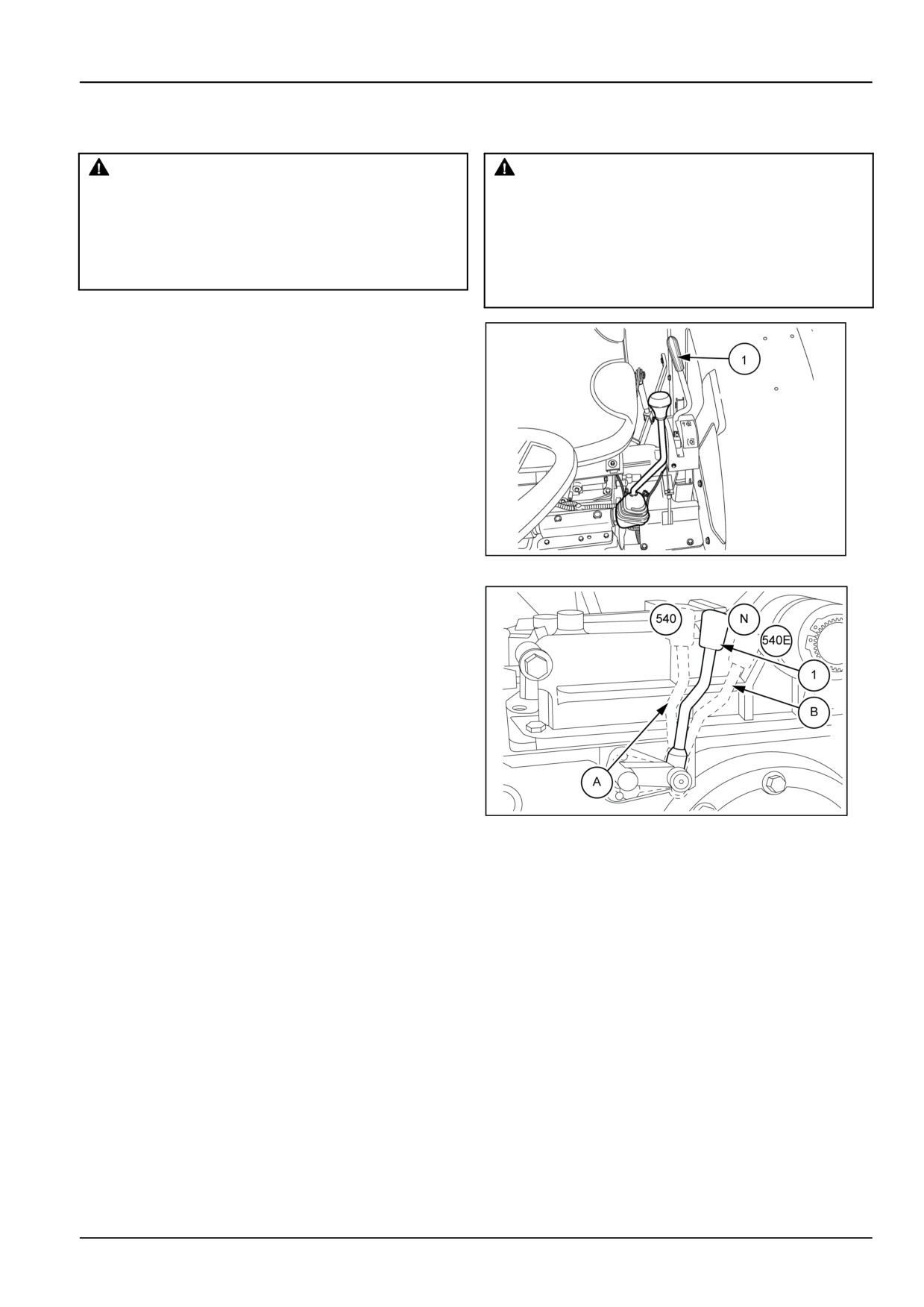
The Power Take-Off (PTO) lever (1) is located on the left-
hand side of the operator’s platform. The PTO lever (1) is
used to engage or disengage the power transmission to
the rear PTO shaft from engine.
A standard speed of 540 RPM PTO can be obtained at an
engine speed of 2575 RPM .
Shift the lever (1) forward to engage the PTO and rear-
ward to disengage the PTO.
86090124N
1
Power Take-Off (PTO) Lever
A standard speed of 540 RPM PTO can be obtained at
an engine speed of 2575 RPM and 540E RPM can be ob-
tained at an engine speed of 2016 RPM.
Shift lever (1) to position (A) to get PTO 540 RPM and
shift the lever (1) to position (B) to get PTO 540E RPM .
GNIL14TR00553AA
2
3-17
3 - CONTROLS AND INSTRUMENTS
RIGHT-HAND SIDE CONTROLS
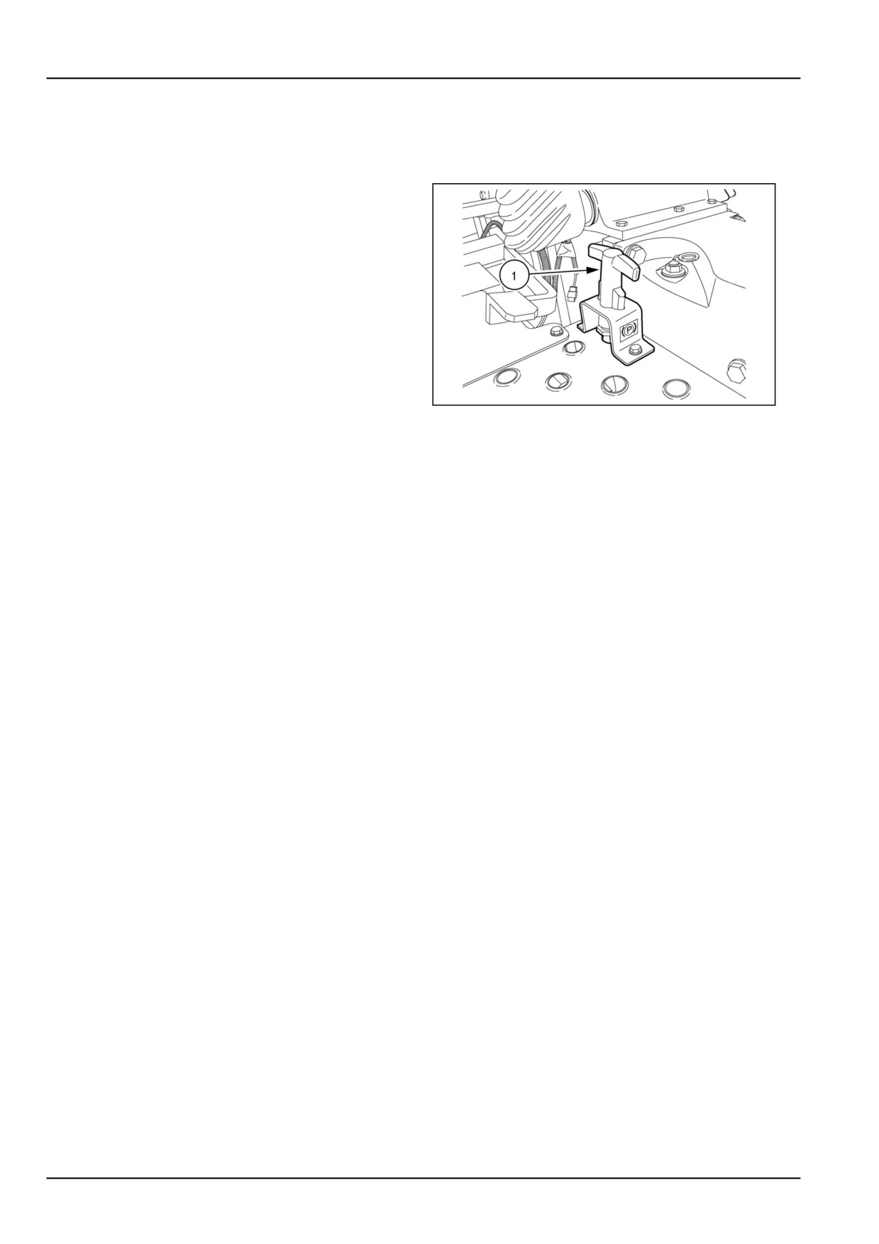
Parking brake
1. The “T” shaped park brake handle (1) is used in con-
junction with the foot brakes.
2. To apply the park brake, first pull up the “T” handle and
lock the "T" shaped handle in place by rotating 90 °
3. Then press the brake pedals firmly and release after
ensuring the pawl of the park brake is locked in one of
the teeth of ratchet provided on the foot brake pedal
lever.
4. To release the park brake, press the foot brake pedal,
rotate the “T” handle 90 °and release the handle and
foot brake pedal.
NOTICE: Ensure that the park brake is fully released be-
86090119N
1
fore driving the tractor.
NOTE: Always apply the park brake when getting off of
the tractor. If the park brake is not applied or operator
leaves the seat without applying the park brake a warning
buzzer will sound for approximately ten seconds.
3-18
3 - CONTROLS AND INSTRUMENTS
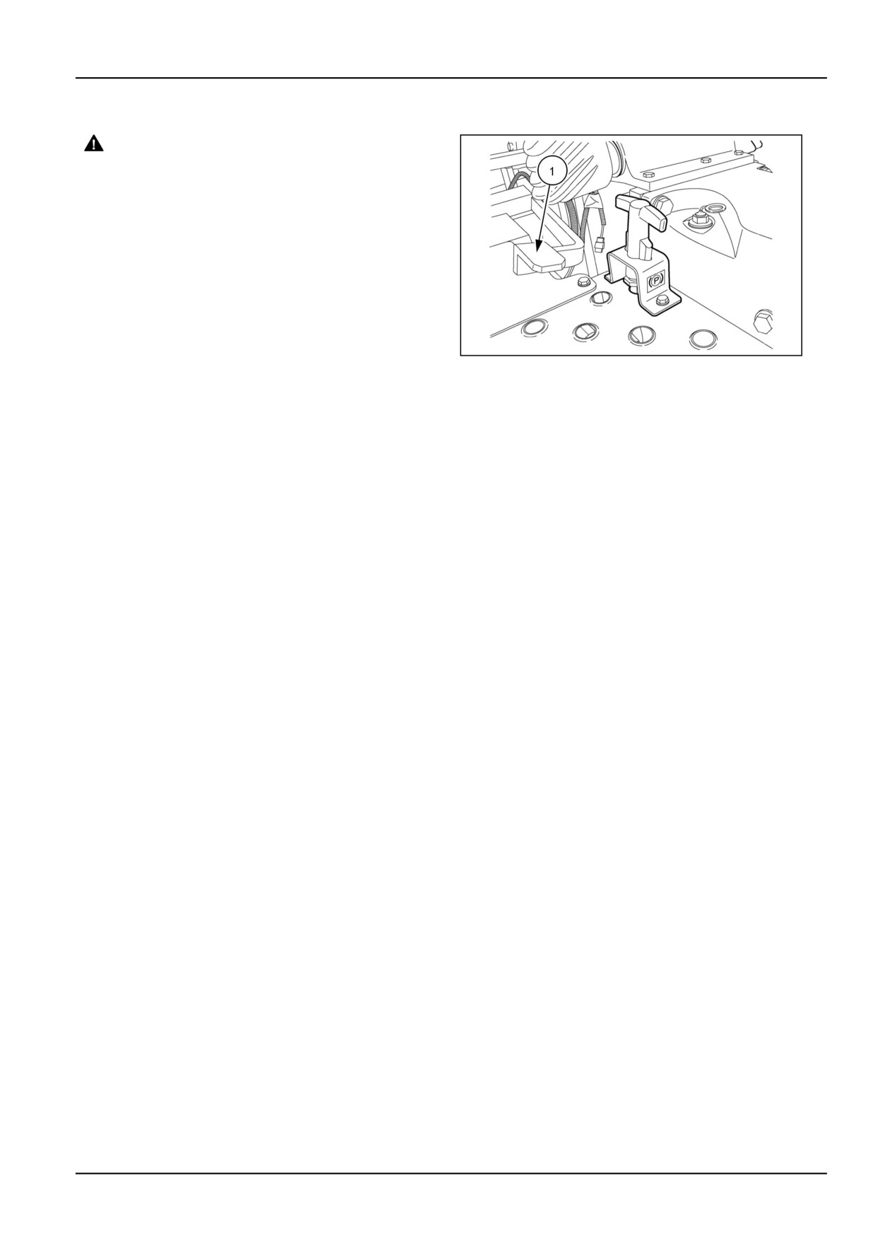
Differential lock pedal
WARNING
Steering is difficult with the differential lock
engaged. An accident could result.
During field operation, use the differential lock
for traction improvement but release for turn-
ing at row end. Do not drive at high speeds or
on roads with the differential lock engaged.
Failure to comply could result in death or se-
rious injury.
W0292A
Differential lock pedal
Depress the differential lock pedal to engage the
86090119N
1
differential lock in the following cases:
• During plowing, to reduce slippage of the land-side
wheel.
• When one of the rear wheels loses grip due to uneven,
muddy, or loose soil.
NOTICE: If one rear wheel spins at higher speed than the
other, reduce the engine speed before trying to engage
the differential lock. This will avoid shock loads and the
risk of damage to the internal components.
3-19
3 - CONTROLS AND INSTRUMENTS
Transmission - Control identification
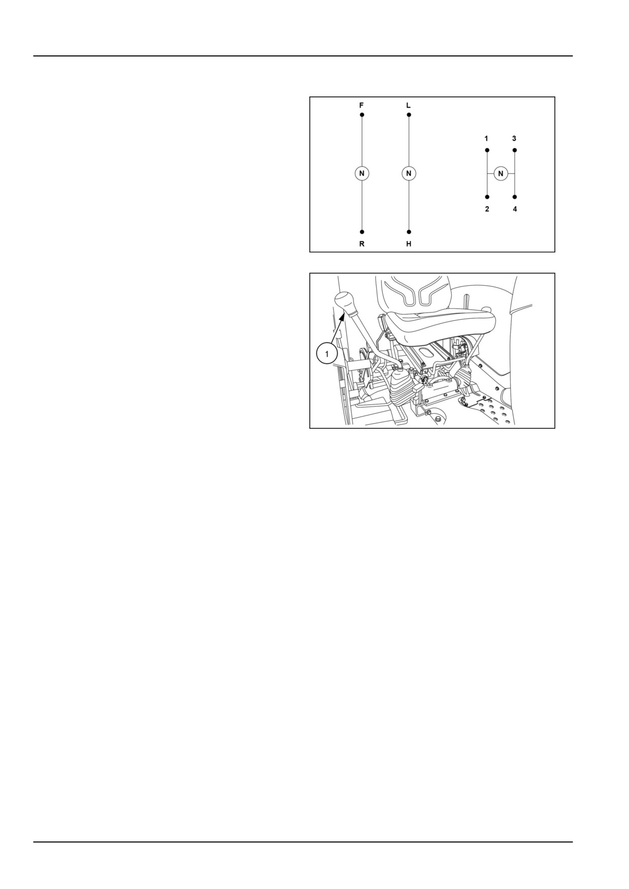
Transmission main shift lever
The main transmission shift lever (1) operates in an H-Pat-
tern. To change the gears while in the selected range;
depress the clutch pedal, stop the tractor, and shift main
gear lever into the desired gear.
GNIL14TR00513AC
1
The main transmission shift lever (1) is used to select any
one of the four forward or reverse gears.
GNIL14TR00785AA
2
3-20