New Holland Tractor Workmaster 50 / Workmaster 60 / Workmaster 70 / Tier 4B (final). SERVICE MANUAL - page 30
7 - MAINTENANCE
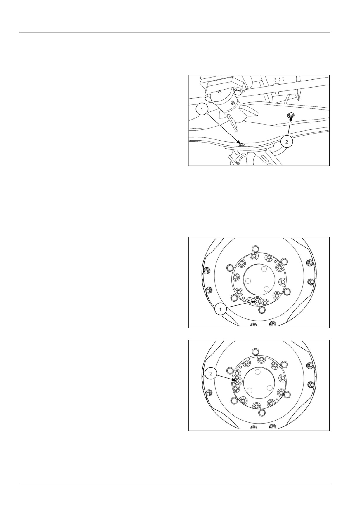
Four-Wheel Drive (4WD) front axle differential oil - Change fluid
1. Remove the drain plug (1) and collect the oil in a suit-
able container.
2. Replace the plug and fill the differential with oil at fill
plug (2) until oil level is at the bottom of the fill port.
96096503
1
3. Add NEW HOLLAND AMBRA MULTI G 134™ HY-
DRAULIC TRANSMISSION OIL hydraulic oil through
fill port, until correct oil level is obtained.
4. The capacity for the differential is 5.5 l (5.8 US qt).
Four-Wheel Drive (4WD) front axle hub oil - Change fluid
1. Drain the front axle hub oil by positioning the wheel so
the filler plug (1) is closest to the ground. Remove the
plug and allow the oil to drain.
76073648N
1
2. Reposition the wheel so the filler hole (2) is level with
the center of the hub, midway from the top to the bot-
tom. Fill the hub until the oil level is at the bottom of the
fill port.
3. Add NEW HOLLAND AMBRA MULTI G 134™ HY-
DRAULIC TRANSMISSION OIL hydraulic oil through
fill port, until correct oil level is obtained. The capacity
for the hub is 1.2 l (1.3 US qt).
76073647N
2
7-36
7 - MAINTENANCE
Air filter
NOTICE: The outer element may be dry cleaned every 300 h of operation or when warning bulb glows (which ever is
earlier). Outer element to be replaced after four times of cleaning or maximum of 1200 h Inner element to be replaced
with outer element replacement or every 1200 h.
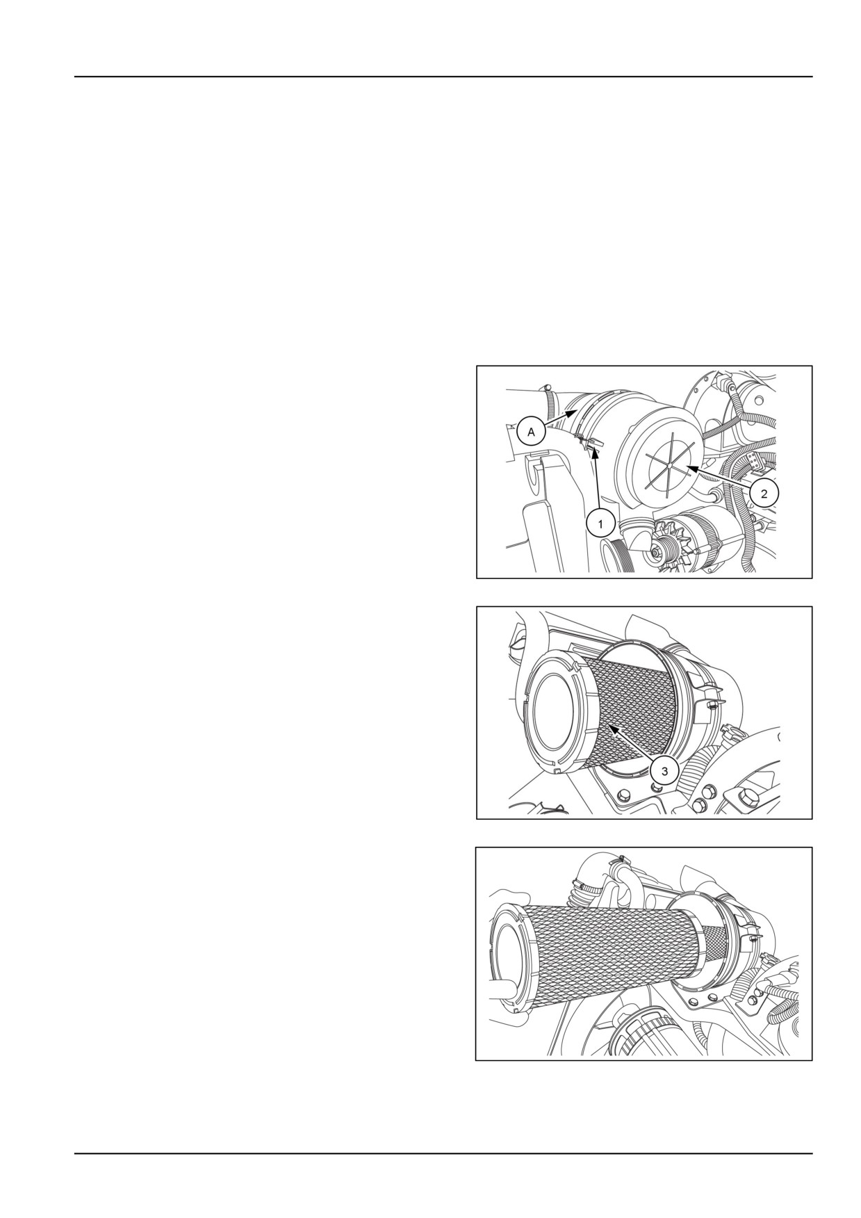
The air cleaner assembly (A) is located under the right-
hand side of the engine hood. The air cleaner assembly
consists of an inner and outer paper element within a
metal housing.
Engine air cleaner outer element replacement
The air cleaner (A) which is located under the hood,
consists of an inner and outer paper element within a
metal casing.
1. Unlatch the three retaining clips, (1) and lift off the air
cleaner assembly cover (2).
GNIL14TR00501AA.PNG
1
2. Remove the outer element (3). from the air cleaner as-
sembly by gently twisting the end of the filter clockwise
to disengage the seal.
GNIL14TR00502AA.PNG
2
3. Then pull the filter straight out of the housing, not at an
angle.
GNIL14TR00503AA.PNG
3
7-37
7 - MAINTENANCE
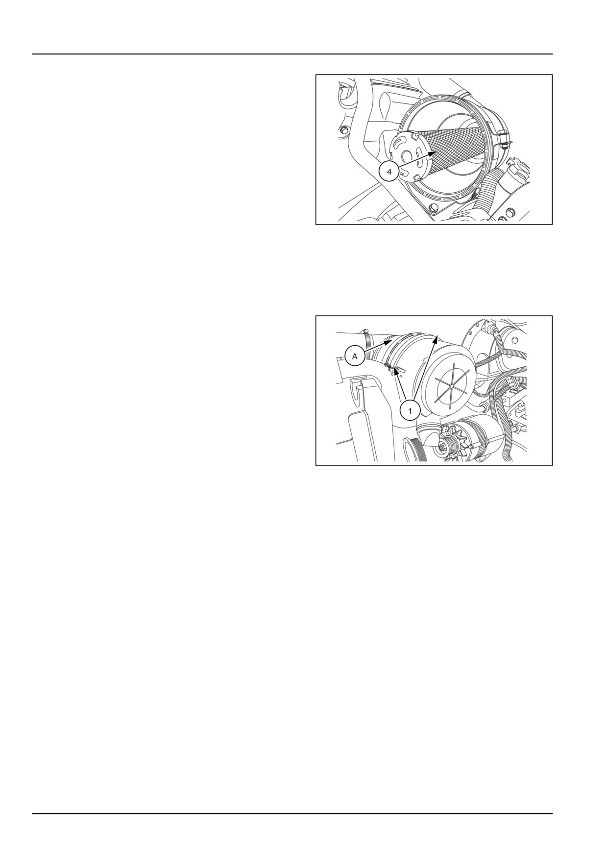
4. Make sure the inner element (4) remains in place.
GNIL14TR00504AA.PNG
4
5. Clean inside of air cleaner housing and check that the
sealing surfaces for inner and outer elements are clean.
6. Install new inner and outer air cleaner elements into
housing. Make sure that both elements seals are
seated against the inside of the air cleaner housing.
7. Reinstall cover (2) and secure cover to air cleaner
housing with the three retaining clips (1).
GNIL14TR00501AA.PNG
5
7-38
7 - MAINTENANCE
Power Take-Off (PTO) clutch
The Power Take-Off (PTO) clutch engagement pres-
sure needs to be checked and adjusted to prevent slip-
page of the PTO during operation under load.
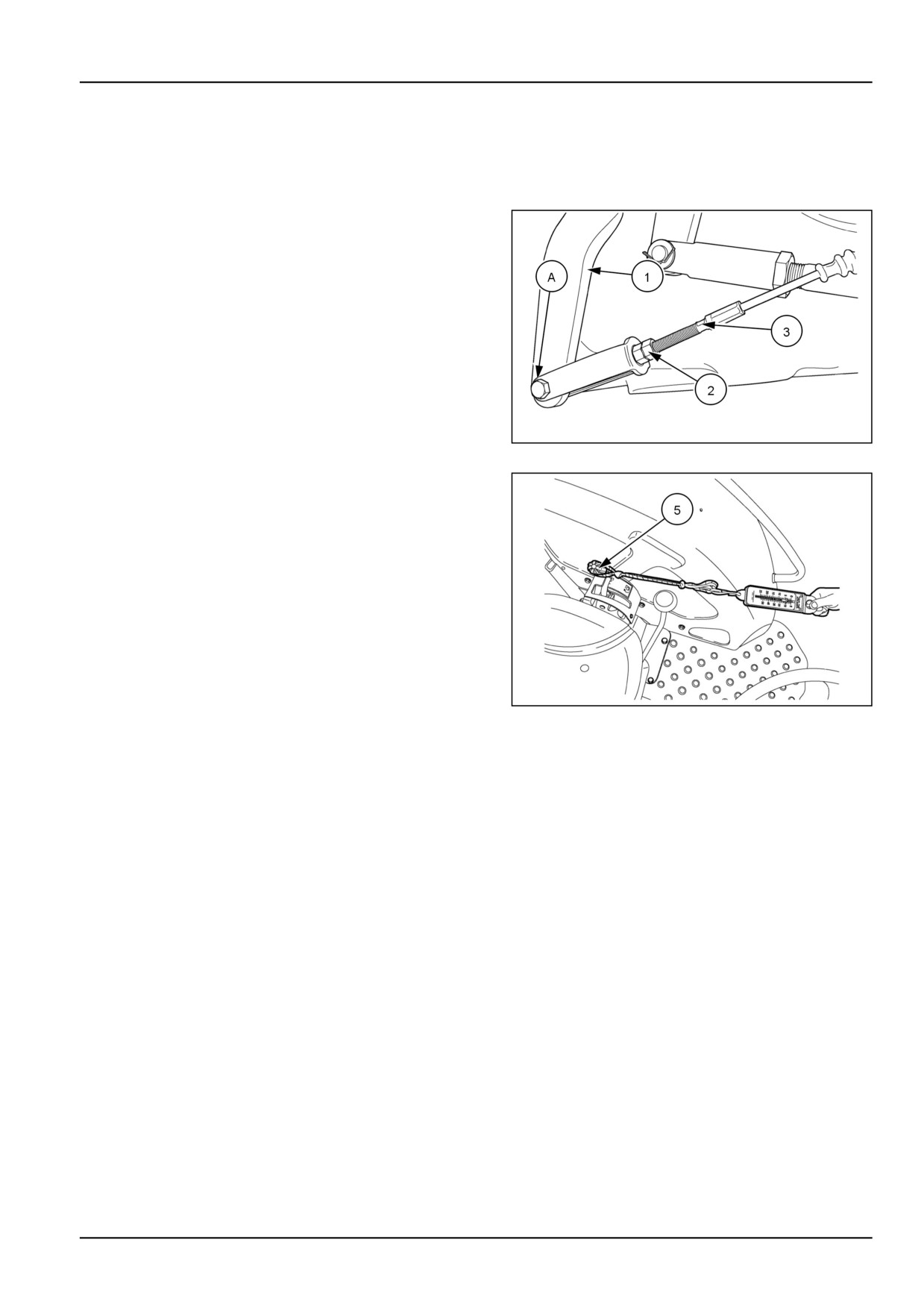
1. When the PTO clutch linkage is properly adjusted, the
PTO lever (1) should have 2 mm (0.079 in) of free play
at pin (A) when the PTO handle is in the "OFF" position.
2. If the free play of lever is not correct, adjust by loos-
ening jam nut (2) and shortening or lengthening cable,
(3).
56061331N
1
3. Use a spring scale (4) to measure the force needed
to fully engage the PTO handle (5). Proper amount of
force at end of handle to fully engage the PTO clutch is
125 - 142 N (28 - 32 lb)
86090136N
2
NOTICE: When PTO clutch linkage is properly adjusted, the total cable travel should be 21 mm (0.83 in) while en-
gaging and disengaging the PTO clutch.
7-39
7 - MAINTENANCE
Every 1800 hours
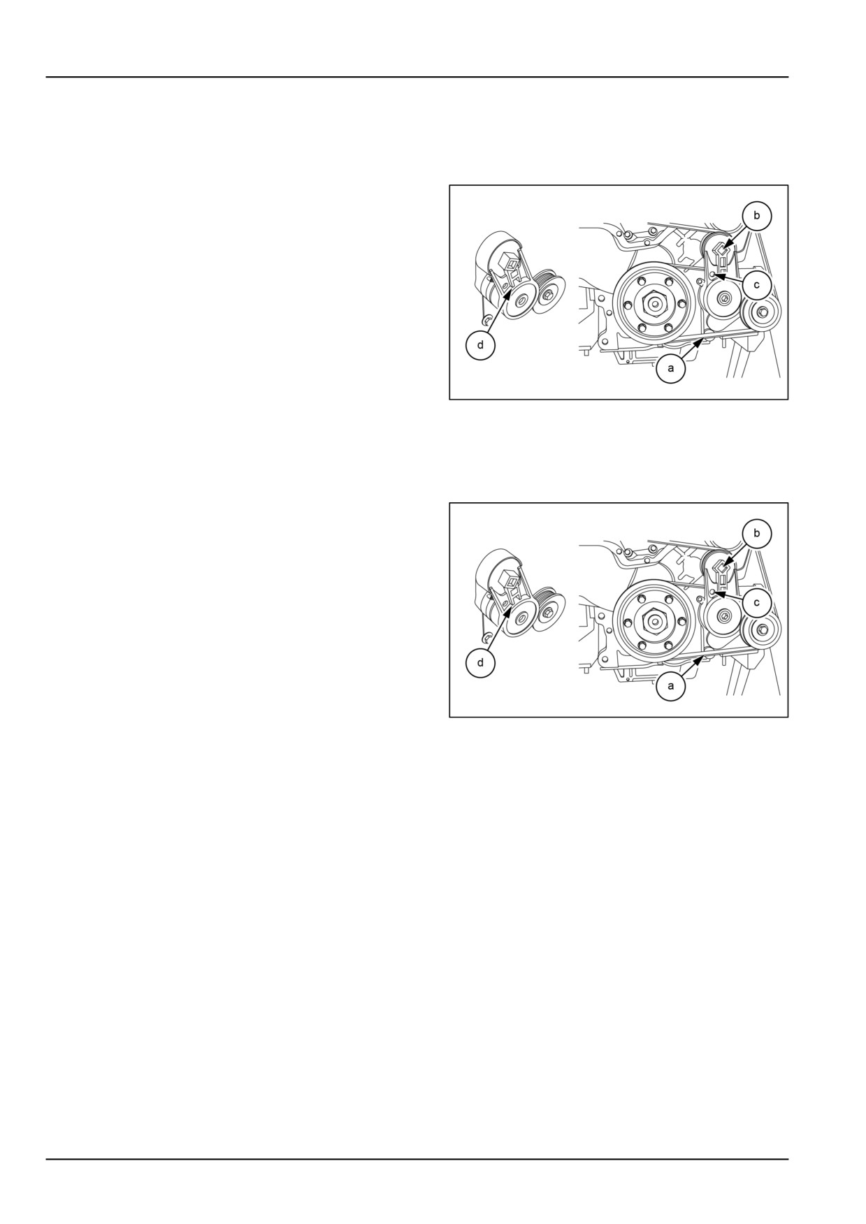
Fan and drive - Replace
1. Position a linear tensioner belt remover tool in the au-
tomatic tensioner release slot.
GNIL14TR00527AA
1
2. Rotate the automatic tensioner, in the direction of the
arrow, to remove the tension on the serpentine belt.
a - Serpentine belt
b - Tensioner release slot
3. Install an allen screw into the tensioner hole to block
the tensioner rotation.
GNIL14TR00527AA
2
4. Before removing the serpentine belt, note the belt po-
sition on the alternator, and idler pulleys.
5. Remove the serpentine belt.
Every 4000 hours
Alternator - Replace
1. Contact your authorized dealer
7-40
7 - MAINTENANCE
As required
Lubrication points
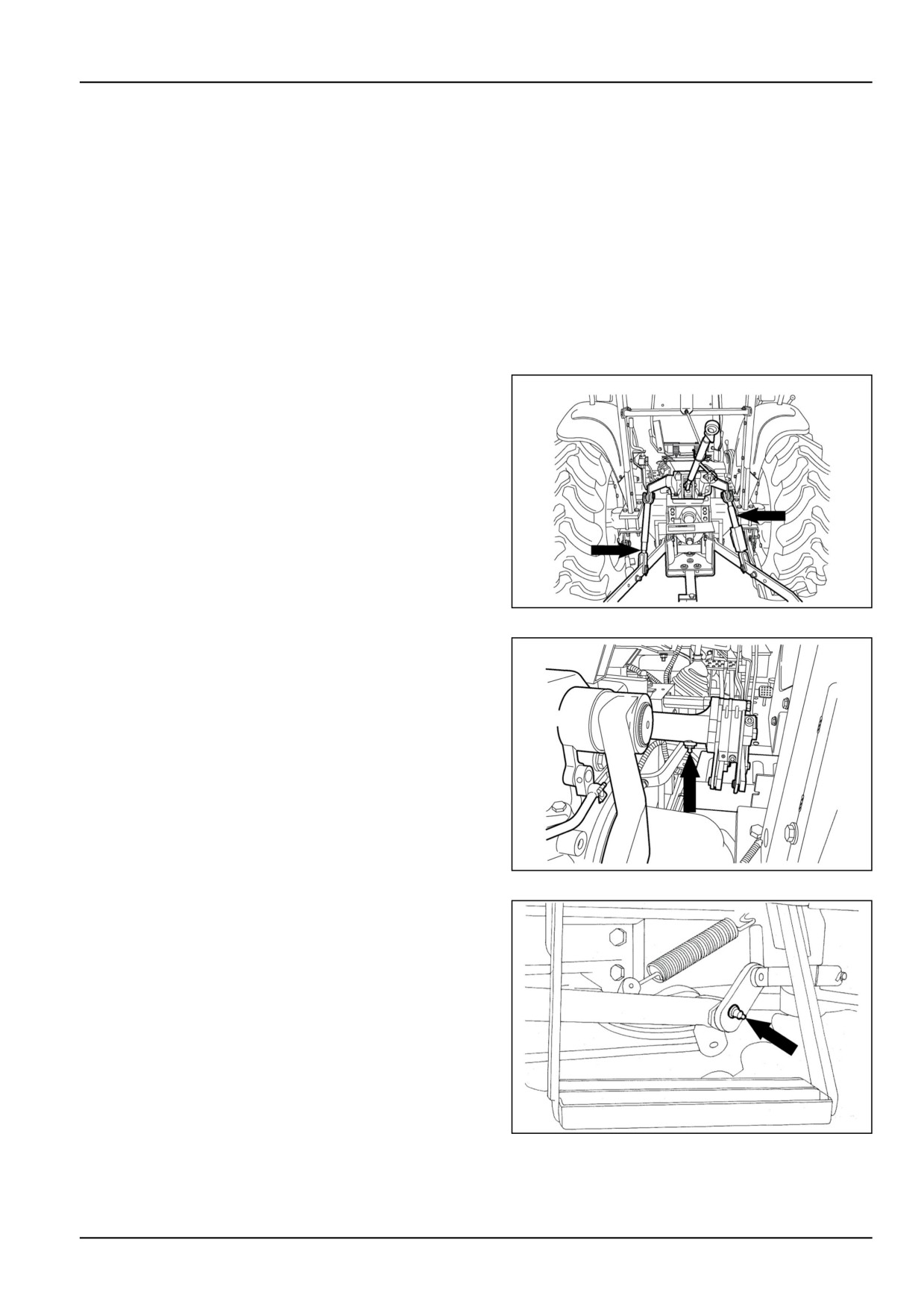
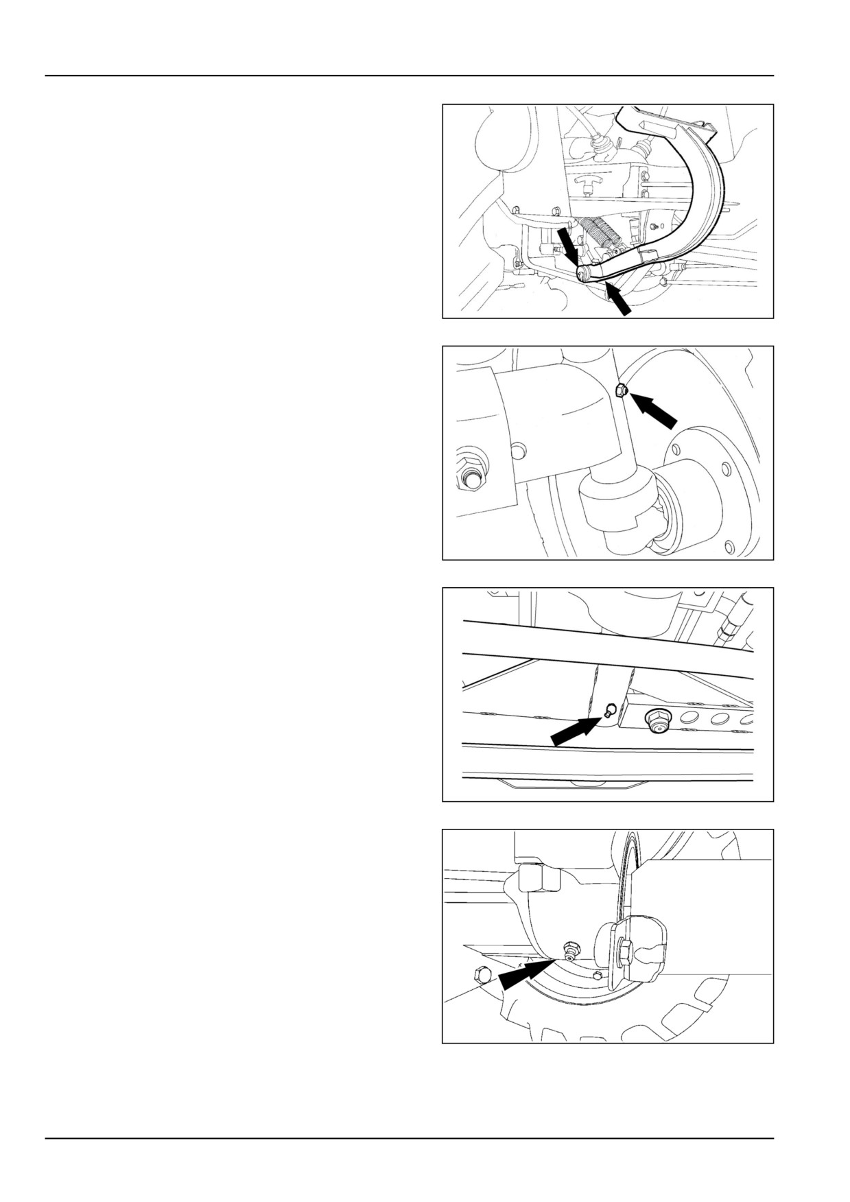
Grease Fittings
Apply grease with the help of a grease gun to the lubri-
cation fittings, as shown in Figures 1 - 11.
Use only Genuine NEW HOLLAND AMBRA GR-9
MULTI-PURPOSE GREASE .
NOTICE: Grease daily when operating in adverse condi-
tions, but do not overgrease, damage to the seals may oc-
cur, where applicable.
1. Hydraulic lift linkages
86090139N
1
2. Hydraulic lift lever shaft
86090131N
2
3. Clutch pedal shaft
20108800
3
7-41
7 - MAINTENANCE
4. Brake pedal shaft
20108801
4
5. Front wheel spindles and hubs (Two-Wheel Drive
(2WD) front axles)
36090133N
5
6. Front axle trunion pin (2WD front axles)
86090132N
6
7. Front axle rear pivot (Four-Wheel Drive (4WD) front
axles)
96096504
7
7-42
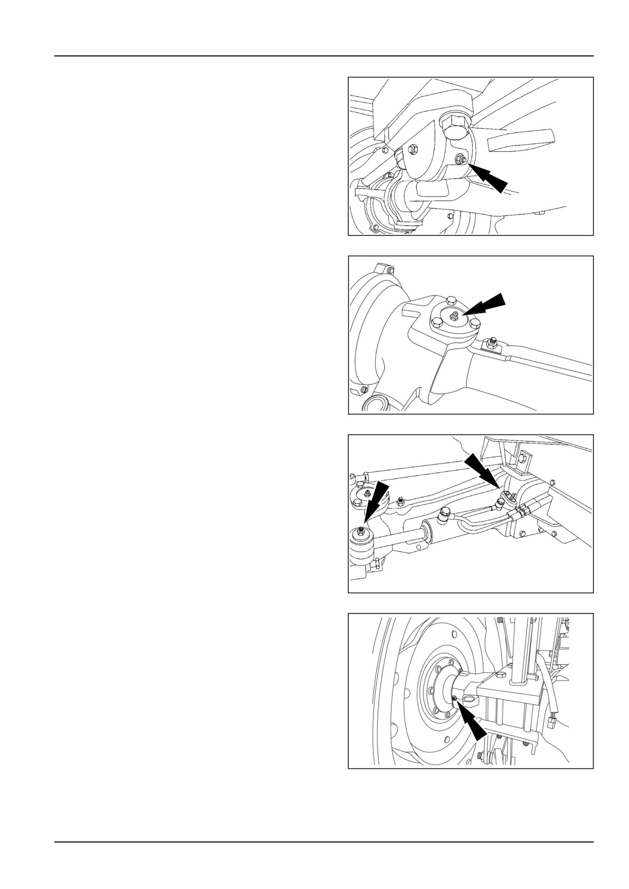
7 - MAINTENANCE
8. Front axle front pivot (4WD front axles)
96096506
8
9. Front axle wheel steering knuckles (4WD)
96096505N
9
10. Steering cylinder pivots (4WD front axle shown).
96096507
10
11. Rear axle seal grease fitting.
GNIL14TR00555AA
11
7-43
7 - MAINTENANCE
Headlights
1. To avoid blinding of on coming drivers, adjust the angle
of the beams. Adjust the head light so that the high
beam is 100 - 400 mm below the centre of the headlight
at a distance of 6 m.
Front headlight bulb — replacement
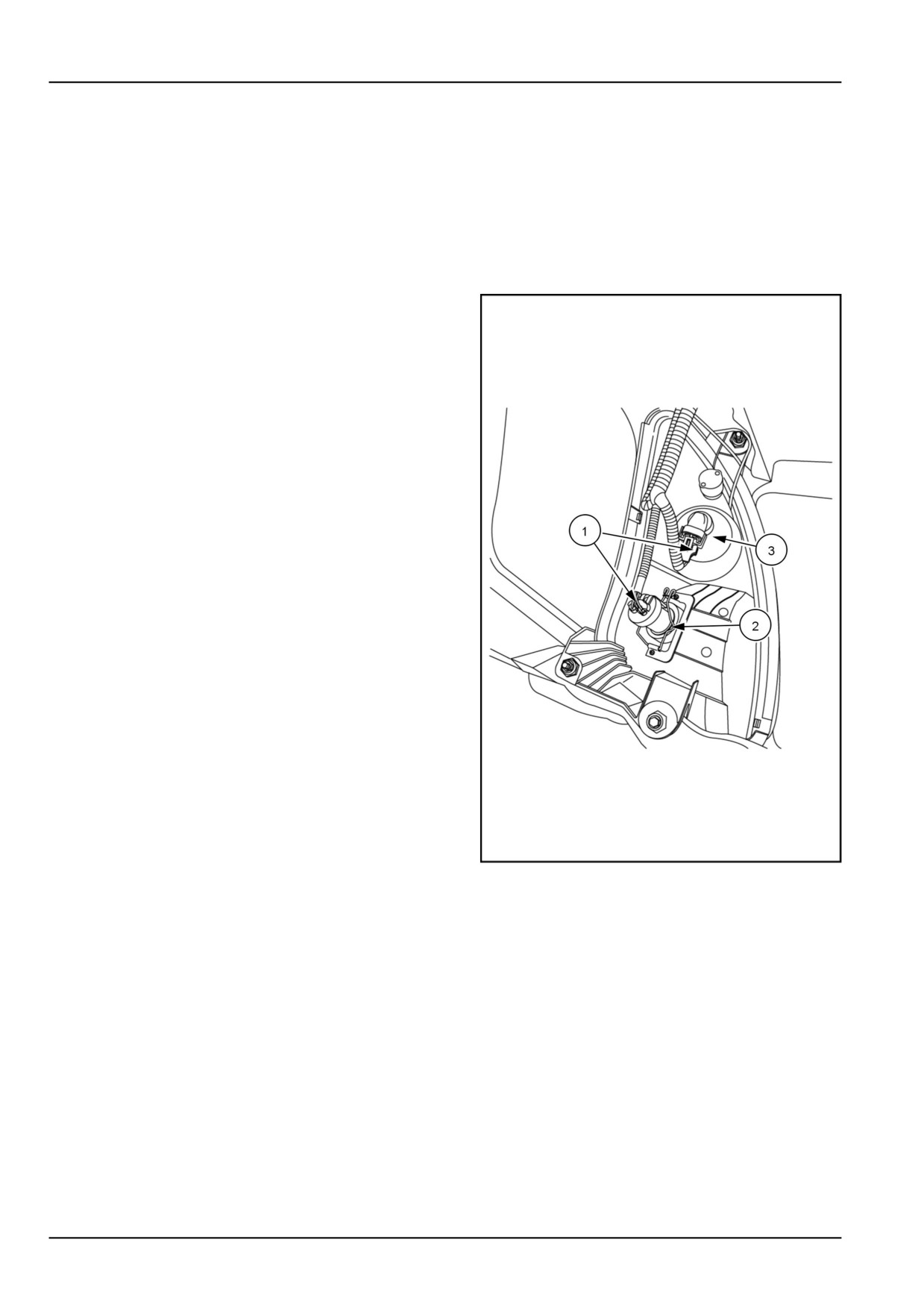
1. Open the tractor hood.
3. Remove the electrical connector (1).
GNIL14TR00534AA
1
4. Compress retaining clip (2) , and remove bulb, (3) ,
from the socket.
5. Insert bulb assembly and secure with retaining clips.
7-44
7 - MAINTENANCE
Fuses
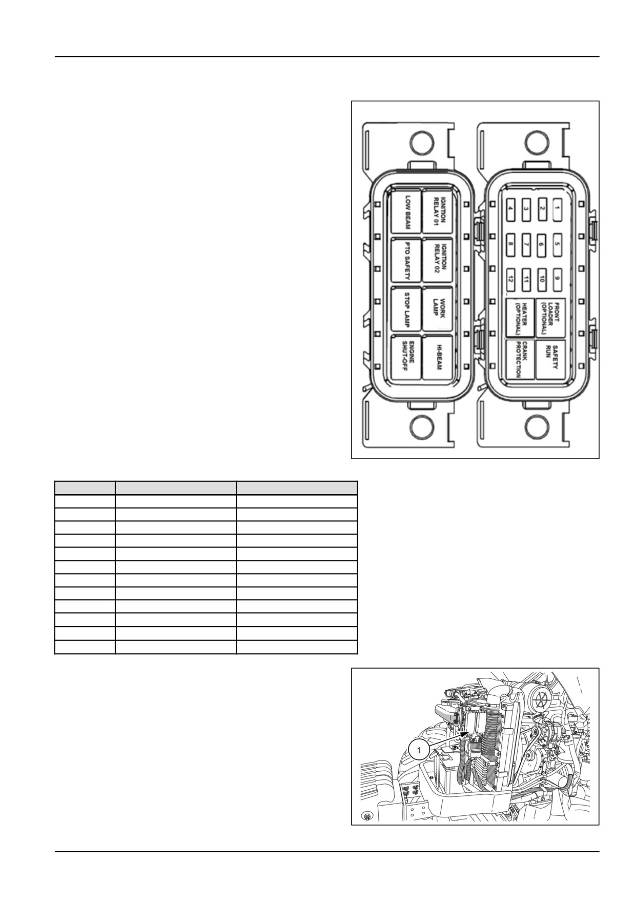
1. The Fuse box is located at the left-hand side of the
intercooler mounted on the ECU frame.
GNIL14TR00507AA
1
Fuse No
Rating
Circuit
1
15 A
Fuse ECU 01
2
10 A
Fuse ECU 01
3
10 A
LAMDA PROBES
4
10 A
Cluster Hot
5
15 A
Work lamp
6
15 A
Hi/Low Beam
7
25 A
Starter SW
8
25 A
Heater
9
5A
Loader
10
10 A
ECU/ Safety Start
11
25 A
Dummy 1
12
15 A
Dummy 2
The fuse box (1) is located at the right-hand rear side
of the engine compartment, mounted on the engine fire-
wall. To access the fuse box, lift the engine hood and
open the fuse box cover to gain access to individual
fuses.
Six fuses are provided in one row. See the following
table for details of the circuits protected by the fuses.
GNIL14TR00529AA
2
7-45
7 - MAINTENANCE
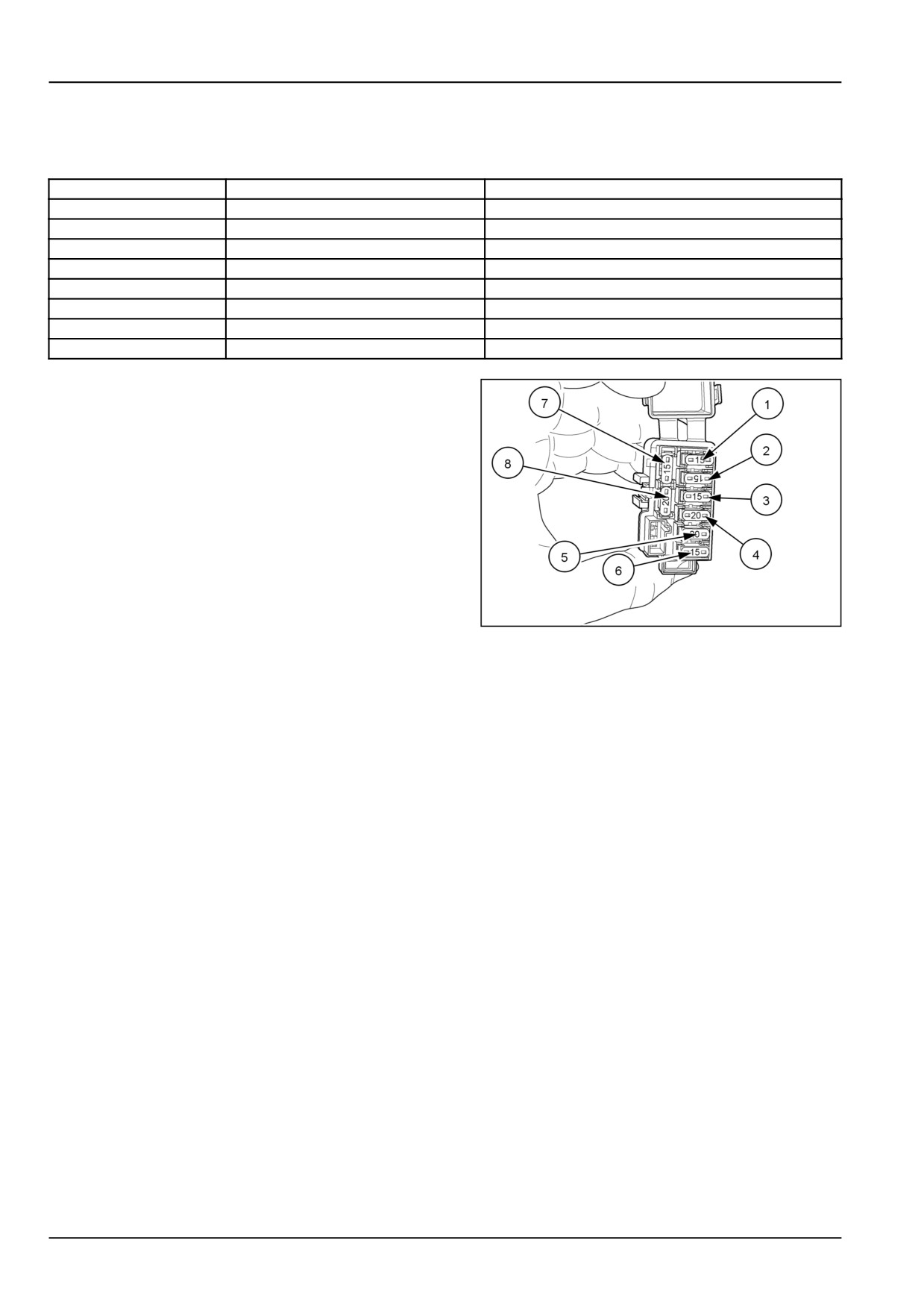
NOTICE: Do not replace a blown fuse with another of a different rating.
Fuse identification
Fuse No.
Rating
Circuit
(1)
15 A
Instrument Panel
(2)
15 A
Safety Start System
(3)
15 A
Horn, Turn Signals
(4)
20 A
Headlights
(5)
20 A
Worklight
(6)
15 A
Hazard Flasher Lights
(7)
15 A
Spare Fuse
(8)
20 A
Spare Fuse
86065632
3
7-46
7 - MAINTENANCE
Bulbs
Stop/Turn/Position lights, bulb replacement
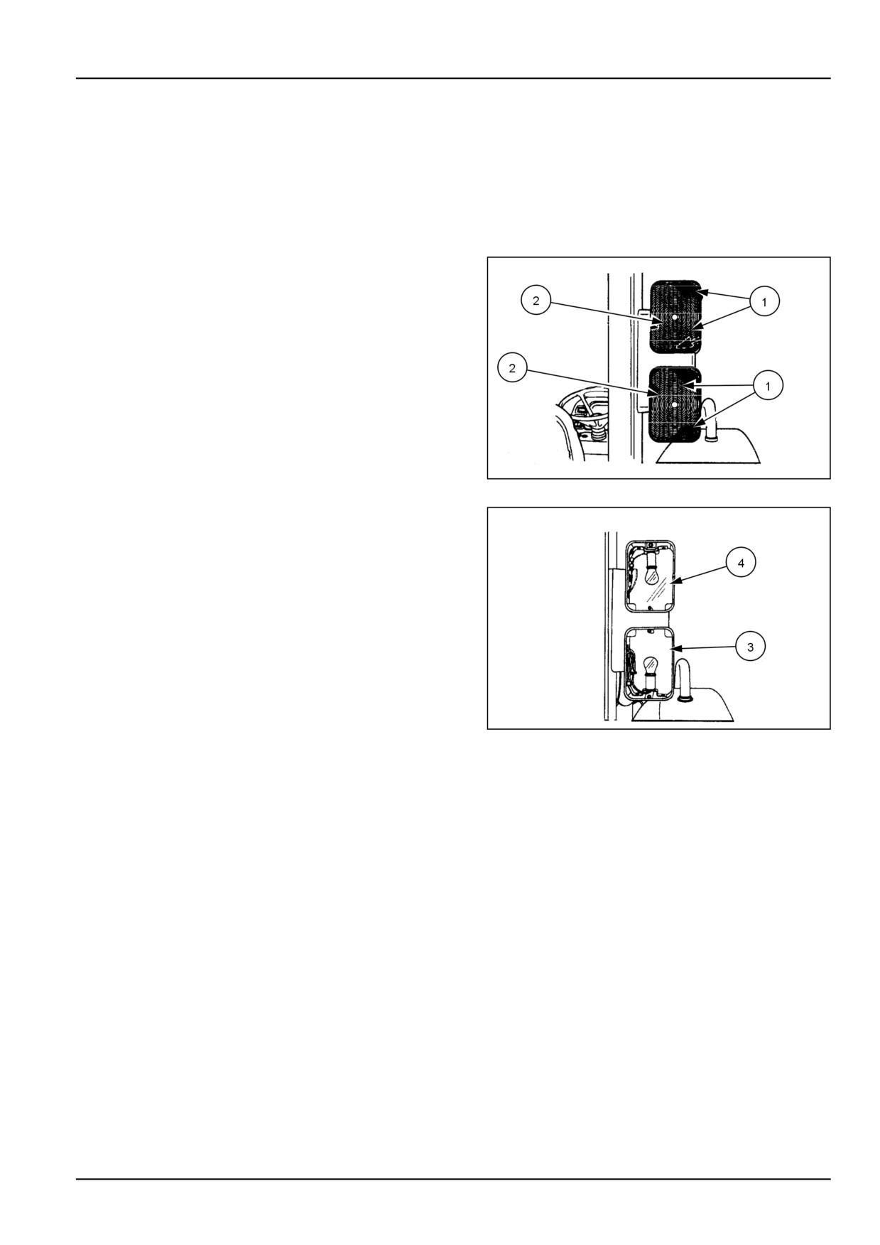
1. The bulbs are accessible after removal of the plastic
lenses assembly.
2. Remove the two screws (1) and take out the lens as-
sembly (2).
3. The bulbs can be removed by pressing in and turning
approximately 20 degree counterclockwise. Reassem-
ble in reverse order.
20108813
1
4. Tail light (3) and flasher/turn signal light (4)
20108814
2
NOTICE: When replacing the lenses, take care not to overtighten the retaining screws.
Bulb Size
• Tail Light - #1157
• Flasher/Turn Signal - #1156
7-47
7 - MAINTENANCE
STORAGE
Tractor storage
The following text is given for your information and guid-
ance. For further information concerning long term stor-
age of your tractor, please consult your Authorized New
Holland Dealer.
Tractor storage
Before storing the tractor for an extended period, the
following precautions should be taken:
• Clean the tractor.
• Drain the engine and transmission/rear axle and refill
with clean oil.
• Check the radiator coolant level. If storing tractor in
cold weather conditions, check the strength of the
antifreeze, with an antifreeze tester, to verify proper
cold protection.
• Lubricate all grease fittings.
• Using the tractor hydraulic system in Position Con-
trol, raise the lift linkage and support the lift arms in
the raised position.
• Remove the battery and store in a warm, dry atmos-
phere. Recharge periodically.
• Raise the tractor and place supports under the axles
to take weight off the tires.
Preparation for use after storage
After extended storage, prepare the tractor for further
use, as follows:
• Inflate the tires to the correct pressure and lower the
tractor to the ground.
• Refill the fuel tank.
• Check the radiator coolant level.
• Check all oil levels.
• Install fully charged battery.
• Remove the exhaust pipe covering.
• Start the engine and check that all instruments and
controls are functioning correctly. Using the tractor
hydraulic system in Position Control, fully raise the
lift linkage and remove the supports.
• Drive the tractor without load to ensure that it is op-
erating satisfactorily.
7-48
7 - MAINTENANCE
Touch-up Paint
The following New Holland paints are recommended for
touch-up paint repairs.
Color
Part No.
Amount
New Holland Bright Blue
86109144DS
16 oz Spray
86109141DS
Quart
CNH Dark Gray
B96104
16 oz Spray
B96105
Quart
Bianco White (Wheels)
9624698-DS
16 oz Spray
9624699-DS
Quart
Med Gloss Black
94792-DS
16 oz Spray
9624700-DS
Quart
7-49
8 - TROUBLESHOOTING
8 - TROUBLESHOOTING###_8_###
SYMPTOM(S)
Viewing error codes
Error codes transmission
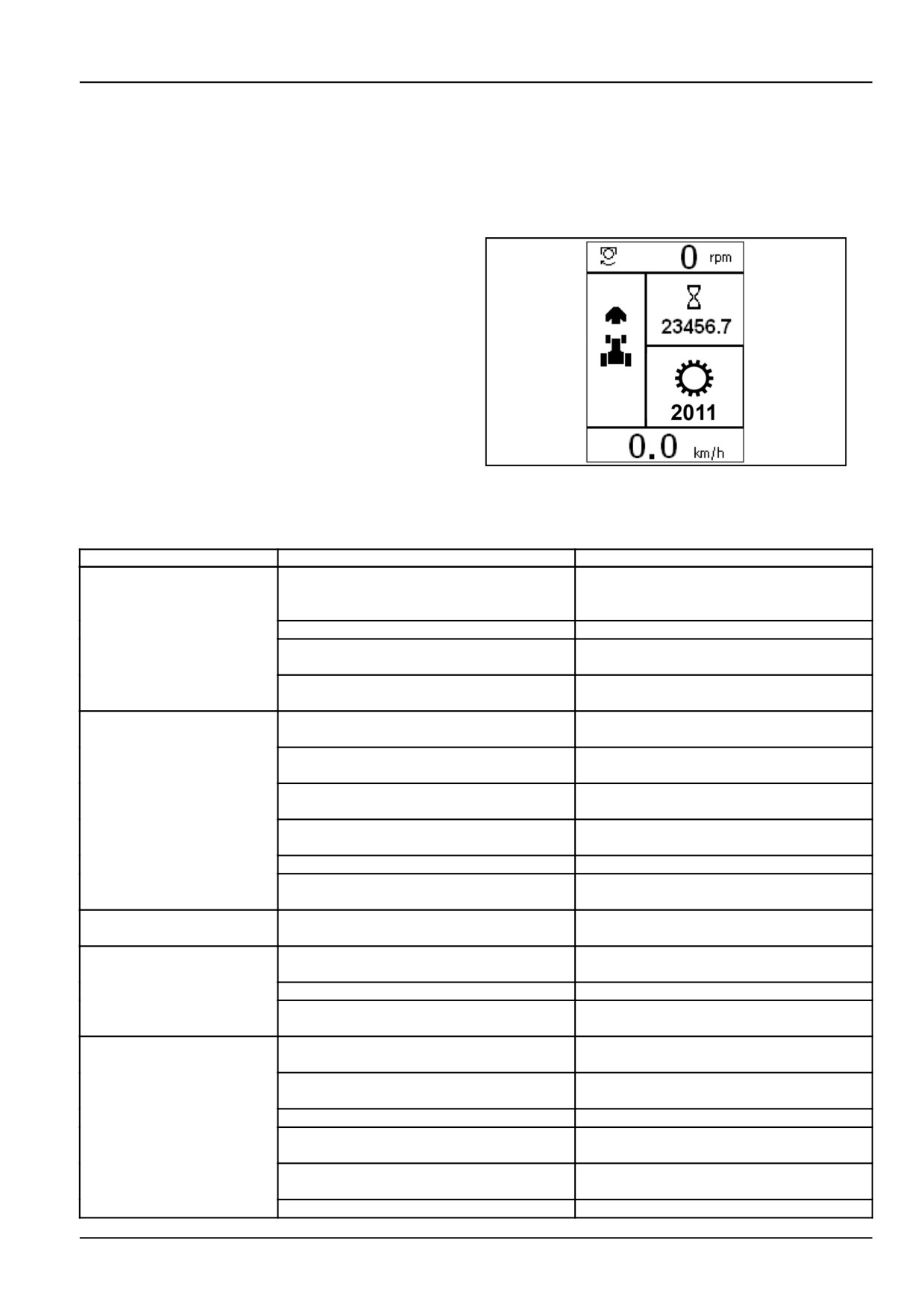
The tractor's electronic control units are able to detect op-
erating faults or errors occurring in key areas such as the
engine, gearbox, electric systems.
Should a malfunction or error occur, the relevant symbol
and error code will appear in the display.
This display may be accompanied by the amber or red
warning lights on the control panel coming on and by an
audible warning, depending on the severity of the fault.
Contact your NEW HOLLAND authorized dealer's spe-
cialized personnel where envisaged.
DCAPLT5NE002S8A
1
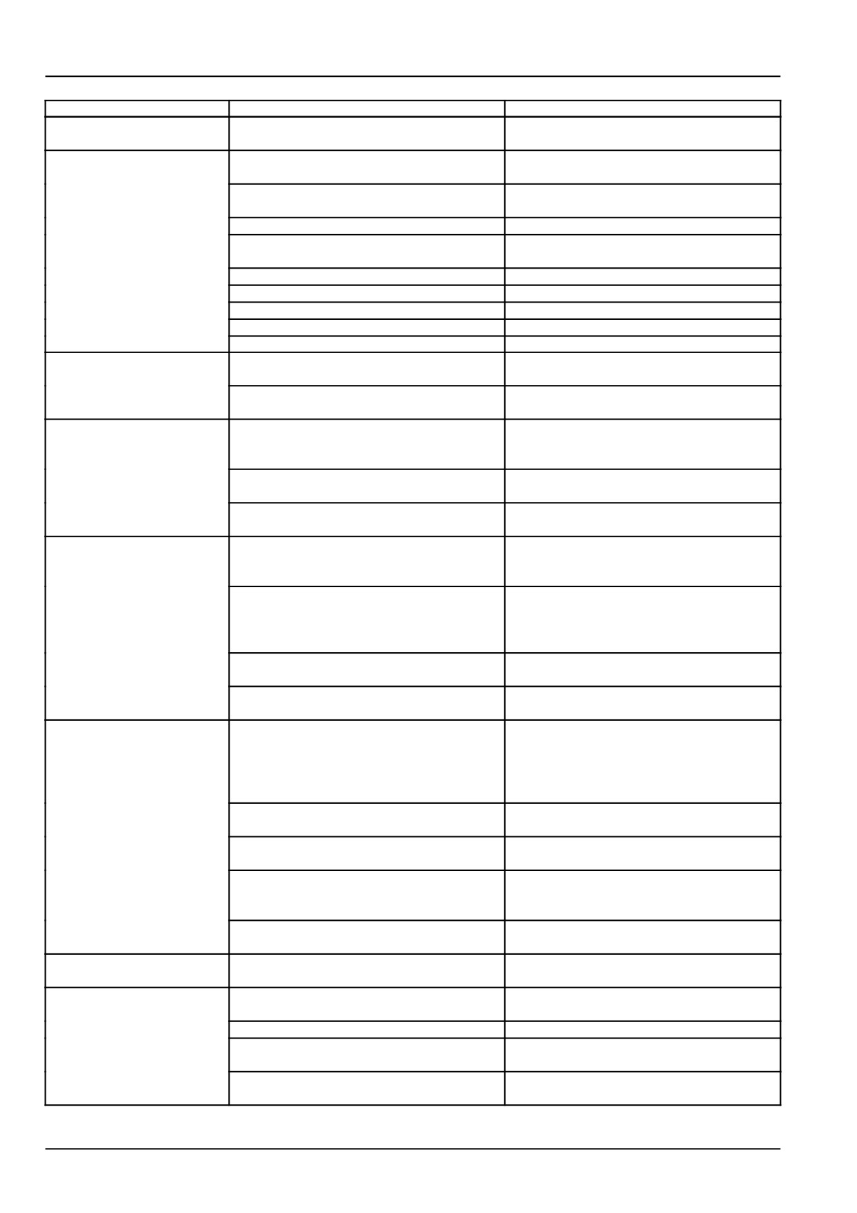
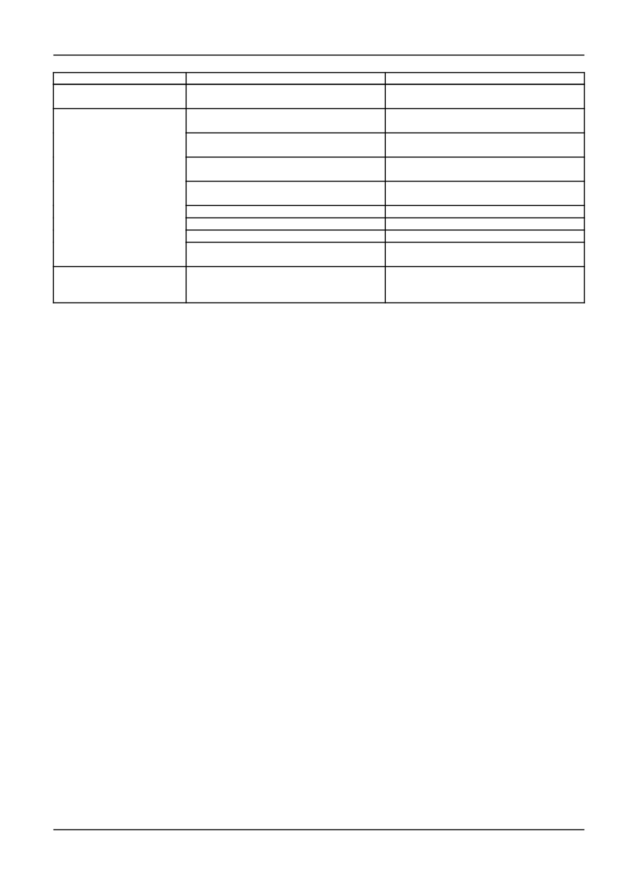
Engine - Troubleshooting
Problem
Possible Cause
Correction
During the ignition phase
Flat battery
Recharge or replace battery
the control board and the
engine do not start.
Blown fuse
Replace fuse
The electric cables are disconnected
or
Check the electric connections
they do not guarantee continuity
Failure of engine revolution sensor
Replace the sensor
Apply to a service workshop
The engine does not start
Presence of air in the fuel supply circuit
Carry out bleeding (See “Fuel supply circuit
bleeding”)
Dirty or faulty injectors
Replace the injectors
Apply to a service workshop
Faulty fuel pressure regulation valve
Replace the valve
Apply to a service workshop
Failure of the start control
Replace the start control
Apply to a service workshop
water and/or impurities in the fuel
Apply to a service workshop
Clogged fuel filter
Replace filter
(See
“Fuel filter replace-
ment.”)
The starter motor runs
Electromagnet failure
Check the starter motor
idle
Apply to a service workshop
The starter motor is not
Flat battery
Recharge or replace battery
running
Interrupted electric connection
Check the electric connections
Worn brushes
Replace the worn brushes
Apply to a service workshop
The engine stops after
Presence of air in the fuel supply circuit
Carry out bleeding (See “Fuel supply circuit
ignition
bleeding”)
Clogged fuel filter
Replace filter
(See
“Fuel filter replace-
ment.”)
Injection pump malfunction
Apply to a service workshop
Faulty fuel pressure regulation valve
Replace the valve
Apply to a service workshop
Presence of air in the fuel supply circuit
Carry out bleeding (See “Fuel supply circuit
bleeding”)
Water and/or impurities in the fuel
Apply to a service workshop
8-1
8 - TROUBLESHOOTING
Problem
Possible Cause
Correction
The engine stops after
The electric cables are disconnected
or
Check the electric connections
ignition
they do not guarantee continuity
The engine does not reach
Clogged fuel filter
Replace filter
(See
“Fuel filter replace-
the operating speed
ment.”)
Presence of air in the fuel supply circuit
Carry out bleeding (See “Fuel supply circuit
bleeding”)
Injection pump malfunction
Apply to a service workshop
Dirty or faulty injectors
Replace the injectors
Apply to a service workshop
Water and/or impurities in the fuel
Apply to a service workshop
Clogged air filter
Clean or replace the filter
Insufficient combustion air flow
Apply to a service workshop
Engine overheating
Apply to a service workshop
Overload
Reduce the load
Emission of black smoke
Dirty or faulty injectors
Replace the injectors
from the exhaust pipe
Apply to a service workshop
Faulty turbocharging turbine
Replace the turbine
Apply to a service workshop
Light emission of white
oil level too high
Adjust the oil level
smoke from the exhaust
pipe
Worn segments
Check compression
Apply to a service workshop
Worn valve guideways
Check wear
Apply to a service workshop
Abundant emission of
Burnt gasket head
Apply to a service workshop
white smoke from the
exhaust pipe
Water pump malfunction
Replace the pump
Apply to a service workshop
Replace the belt (See “Changing the belt
(type Poly-V)”)
Thermostat valve malfunction
Replace the valve
Apply to a service workshop
Coolant too low
Top up, if necessary (See “Engine coolant
level check”)
The pressure gauge
Failure of pressure gauge
Check or replace the pressure gauge
shows a too low engine
Apply to a service workshop
oil pressure and the
corresponding warning
light comes on
Oil level too low
Adjust the oil level (See “Engine oil level
control”)
Oil pump failure
Check or replace the pump
Apply to a service workshop
Faulty sensor
Check and, if appropriate, replace the sen-
sor.
Apply to a service workshop
Engine oil filter blocked
Replace the engine oil filter (See “Oil filter
cartridge replacement”)
The oil pressure warning
Engine oil pressure too low
Turn off the engine. Apply to a service
light comes on
workshop
The coolant temperature
Coolant too low
Adjust the engine coolant level (See “En-
warning light comes on
gine coolant level check”)
Stuck overpressure valve of the load plug
Replace the plug
Water pump malfunction
Replace the pump
Apply to a service workshop
Thermostat valve malfunction
Replace the valve
Apply to a service workshop
8-2
8 - TROUBLESHOOTING
Problem
Possible Cause
Correction
The coolant temperature
Broken or worn belt
Replace the belt (See “Changing the belt
warning light comes on
(type Poly-V)”)
Output reduction
Clogged fuel filter
Replace filter
(See
“Fuel filter replace-
ment.”)
Presence of air in the fuel supply circuit
Carry out bleeding (See “Fuel supply circuit
bleeding”)
Injection pump malfunction
Replace the pump
Apply to a service workshop
Dirty or faulty injectors
Replace the injectors
Apply to a service workshop
Clogged air filter
Clean or replace the filter
Engine overheating
Apply to a service workshop
Insufficient combustion air flow
Apply to a service workshop
Particulate filter is clogged
The particulate filter regeneration is neces-
sary
The battery warning light
The alternating current generator does not
Check and, if appropriate, replace the alter-
comes on
charge the battery
nating current generator
Apply to a service workshop
8-3
8 - TROUBLESHOOTING
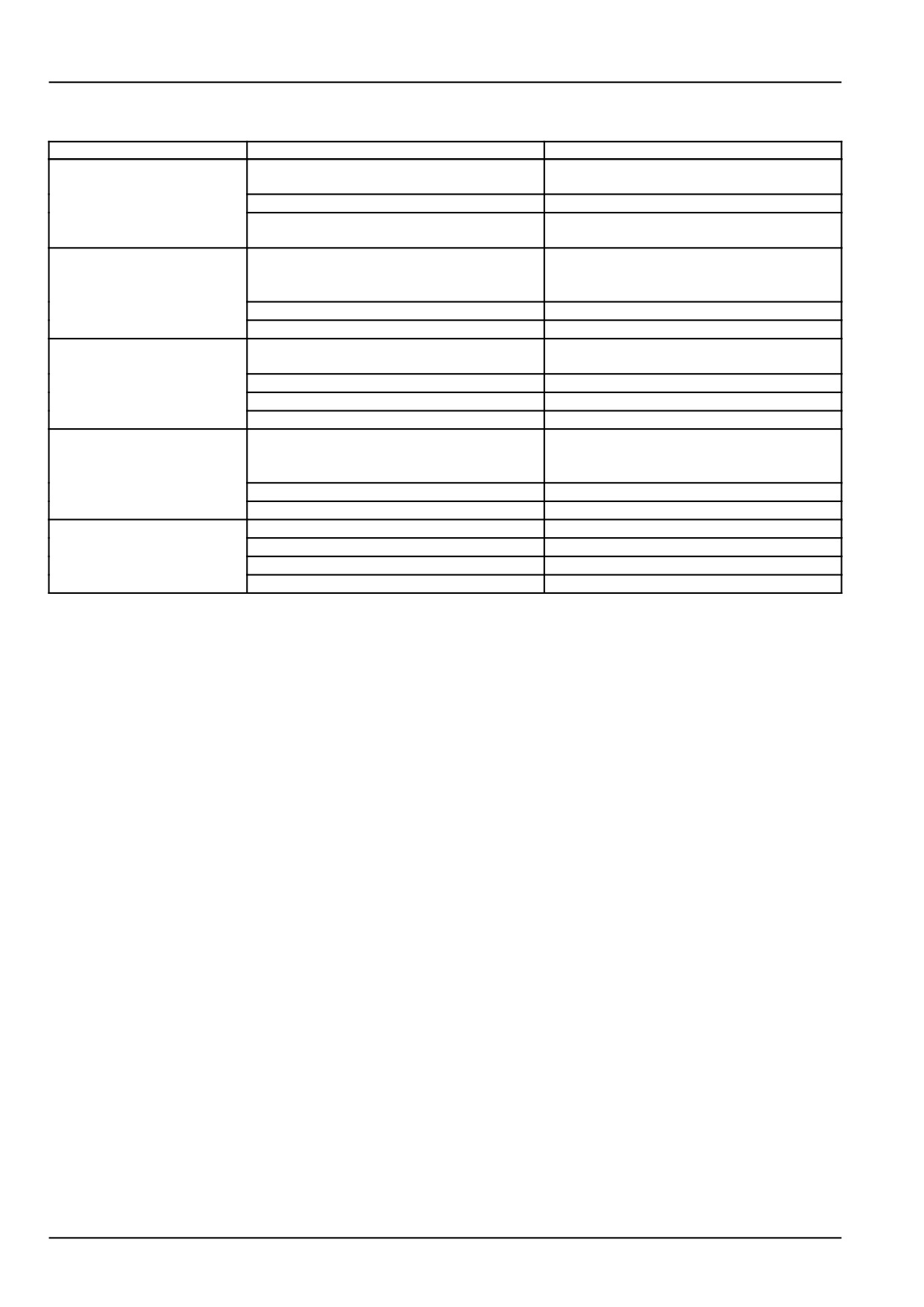
Electrical systems - Troubleshooting
Problem
Possible Cause
Correction
The electrical system
Battery terminals loose or corroded.
Clean and tighten battery terminals.
does not work.
Discharged battery.
Charge or replace battery.
Fusible link wire failure.
Check for cause of failure and replace
fusible link.
Low starter motor speed
Connections loose or corroded.
Clean and tighten terminals.
and difficulty in starting
engine.
Battery discharged.
Charge or replace battery.
Improper ground circuit.
Check and clean ground connections.
Starter motor does not
High-low selector gear & gear shifter levers
Place shift levers in the neutral position.
function.
not in neutral.
Connections loose or corroded.
Clean and tighten connections.
Battery discharged.
Charge or replace battery.
Faulty starter motor.
Replace starter motor.
Battery charge indicator
Fan belt loose or broken.
Adjust belt tension or replace belt.
light illuminates with the
engine running.
Alternator faulty.
Check charging system, repair as needed.
Faulty battery.
Replace battery.
Battery not charging.
Faulty alternator.
Contact your authorized dealer.
Terminals loose or corroded.
Clean and tighten terminals.
Fan belt loose or broken.
Adjust fan belt tension or replace belt.
Faulty battery.
Replace battery.
8-4
8 - TROUBLESHOOTING
Hydraulic systems - Troubleshooting
Problem
Possible Cause
Correction
3-point does not raise
Low hydraulic oil level.
Check hydraulic oil level, add oil as
when the control valve
needed.
lever is actuated.
Hydraulic oil filter clogged.
Replace hydraulic oil filter.
Faulty hydraulic pump.
Contact you authorized dealer.
Control valve linkage misadjusted.
Contact you authorized dealer.
3-point linkage does not
Low hydraulic oil level.
Check hydraulic oil level, add oil as
lift fully.
needed.
Hydraulic oil filter clogged.
Replace hydraulic oil filter.
Control valve linkage misadjusted.
Contact you authorized dealer.
Control valve internally linkage misadjusted
Contact you authorized dealer.
Hydraulic fluid is
Hydraulic control valve not returning to neu-
Return all control valve levers to the neutral
overheating.
tral position.
position.
Hydraulic fluid level is to low.
Check hydraulic fluid level, add oil as
needed.
Hydraulic filter clogged.
Replace hydraulic filter.
3-point linkage lowers
Drop rate speed control misadjusted.
Adjust drop rate control for faster drop
slowly.
speed.
3-point linkage binding
Check for damaged parts or corrosion.
Auxiliary hydraulic
Hose to coupler connections not correct.
Check hose and valve couplers for damage
functions do not function
or contamination.
properly.
Auxiliary system overloaded.
Reduce load on system.
8-5
8 - TROUBLESHOOTING
Brakes and controls - Troubleshooting
Problem
Possible Cause
Correction
Brakes actuate only when
Incorrect brake pedal linkage adjustment.
Adjust brake pedal linkage for proper pedal
pedals are depressed
travel.
fully.
Tractor pulls to one side
Brake pedals linkage not adjusted equally.
Adjust brake pedals linkages equally.
when brakes are applied.
Brakes noisy during
Transmission oil contamination.
Drain and replace transmission oil.
engagement.
Brake discs worn or contaminated.
Replace brake discs.
8-6
8 - TROUBLESHOOTING
Error code identification
NOTE: Should any trouble occur, the central display on the instrument panel will show a warning symbol and a four-
digit error code. To resolve the problem, contact your authorised NEW HOLLAND dealer and report the error code
displayed.
Rear Power Take-Off (PTO) error codes
In the event of problems with the rear power take−off, the following symbol will be displayed
accompanied by a four-digit error code.
8-7
8 - TROUBLESHOOTING
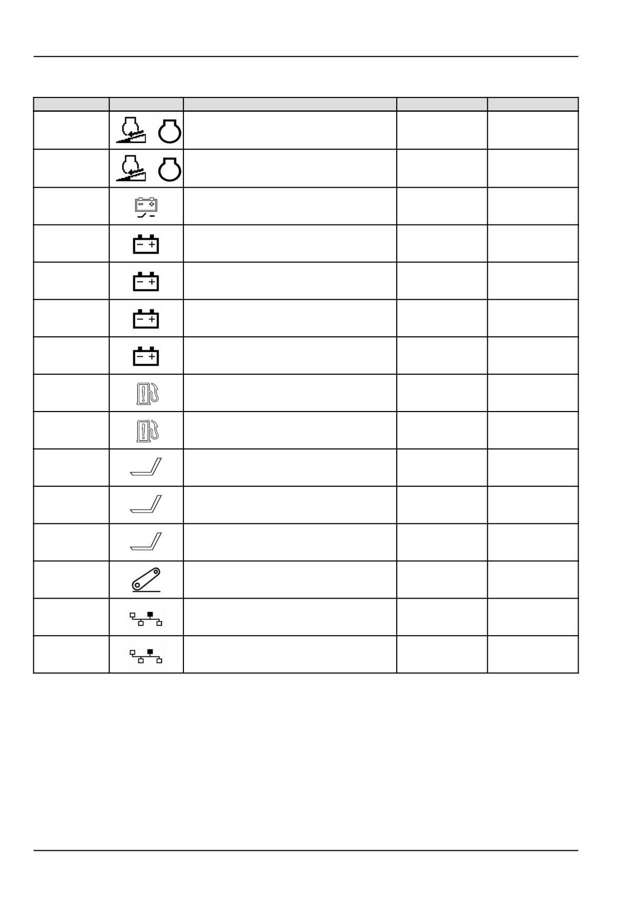
Fault code of digital instrument
FAULT CODE
SYMBOL
Function
Acoustic signal
Warning light on
Automatic regeneration of the diesel
3786
particulate filter (DPF) inhibited; manual
YES
regeneration starting only.
Regeneration of the diesel particulate
3787
filter (DPF) inhibited; contact your dealer
YES
immediately
Battery isolator switch on at key-on for more
14200
then 30 seconds
NO
YES
Supply voltage at 5 V too high
14015
NO
YES
Supply voltage at 5 V too low
14016
NO
YES
Cranking line shorted to +12 V
14021
NO
YES
Cranking line shorted to GND
14022
NO
YES
Fuel sensor short to Vcc or open circuit
14051
NO
YES
Fuel sensor short to GND
14052
NO
YES
Seat switch closed for 25 hours
14058
YES
YES
Seat switch short to Vcc or open circuit
14093
YES
YES
Seat switch shorted to GND
14094
YES
YES
Electronic lift present but not configured
14109
NO
YES
Transmission module missing
14900
NO
YES
Engine module missing
14901
NO
YES
8-8
9 - SPECIFICATIONS
9 - SPECIFICATIONS###_9_###
General specification
Engine
Type/Model
CRDI/VM R753IE4
Emission Level
Tier 4
Engine Net Horsepower
39.5 kW (53.7 Hp)
44.8 kW (60.9 Hp)
52.2 kW (71.0 Hp)
PTO Horsepower
34.0 kW (46.2 Hp)
38.0 kW (51.7 Hp)
46.0 kW (62.5 Hp)
Cylinders
3
Bore
94.0 mm (3.7 in)
Stroke
107.0 mm (4.2 in)
Displacement
2227.0 cm³ (135.9 in³)
Compression Ratio
17.5:1
Firing Order
1-3-2
Aspiration
Turbocharged Intercooler
Low Idle Speed
900±100 RPM
Maximum no-load speed
2750±50 RPM
Rated Speed
2600 ±50 RPM
Tappet Clearance
Intake/Exhaust (cold)
Hydraulically Adjustable
Crankcase Oil Capacity
6.3 L (6.7 US qt)
Capacities
Fuel Tank
65.0 L (17.2 US gal)
Cooling system
10.0 L (10.6 US qt)
Engine Crankcase Oil
6.3 L (6.7 US qt)
Capacity
Rear Axle & Transmission
23.0 L (6.1 US gal) for 2WD
25.0 L (6.6 US gal) for 4WD
Front Axle (Four Wheel
7.5 l (8.0 US qt)
Drive)
Cooling system
Type
Pressurized Liquid with Recirculating bypass
Water Pump
Centrifugal
Drive
poly V-Belt
Belt Deflection
Auto Adjustable
Fan Diameter
415.0 mm (16.3 in)
Number of Fan Blades
8
Thermostat:
Start to Open
80.0 °C (176.0 °F)
Fully Open
95.0 °C (203.0 °F)
Radiator Cap
90 kPa (13 psi)
Antifreeze
Ethylene Glycol
System Capacity
8.3 L (8.8 US qt)
9-1
9 - SPECIFICATIONS
Electrical system
Main System Protection
Mega Fuse 125 A
Number of fuses for protection
6
Alternator
75 A
Battery Type
12 V
Negative Ground
BCI group 47
CCA 600-850
Starter Motor - Type
Solenoid operated
Starter kw (hp) Rating
2.0 kW (2.7 Hp)
Bulb Rating and Type
Head Light
55/65 W
Turn Signal
21 W
Tail Light
21 W / No. 1157
Fuel system
Fuel Type
Diesel
Type of fuel to use
If above 5°C (40°F)
EN590:2009
Type of fuel to use
Biodiesel 5% EN 590
If below 5 °C (40 °F)
Injection Pump:
Type
CRDI
9-2
9 - SPECIFICATIONS
Brakes
Type
Wet Disc
Number of Discs per side
3
Brake Disc Diameter
165 mm (6.5 in)
Pedal Free Travel
50-55 mm
1.96-2.16 in
Steering
Type
Power
Pump flow
21.0 L/min (5.5 US gpm)
Maximum Hydraulic
Steering Pressure
20700.0 kPa (207.0 bar)
Turns Lock to Lock
2WD
3
4WD
3.5
Maximum Steering Angle
2WD
91.4 °
4WD
62 °
Turn Radius
Without Brakes (2WD)
3100.0 mm (122.0 in)
With Brakes (2WD)
3450.0 mm (135.8 in)
Without Brakes (4WD)
4850.0 mm (190.9 in)
With Brakes (4WD)
4200.0 mm (165.4 in)
Power Take-off (PTO)
Type
Independent
Clutch Disc Size
280 mm (11 in)
Clutch Material
OrganicOrganic
Control
Hand Lever, Mechanical
Shaft Size
35 mm (1-3/8 in)
Number of Splines
6
PTO Shaft Rotation
Clockwise (Viewed from rear)
Engine Speed for 540 RPM
2575 RPM
PTO Horsepower
34.0 kW (46.2 Hp)
38.0 kW (51.7 Hp)
46.0 kW (62.5 Hp)
9-3
9 - SPECIFICATIONS
Hydraulic system
Type
Open Center
Pump Type
Gear, engine driven
Pump Capacity
45.0 L/min (11.9 US gpm)
System Relief Valve Setting
19000.0 kPa (190.0 bar)
Number of rear remote available
2
Number of mid remote available
1
Draft Control
Available
3-Point linkage
Category Type
II/I
Lift capacity at ball ends
1100.0 kg (2425.1 lb) / 1500.0 kg (3306.9 lb)
Lift capacity 610mm behind
860.0 kg (1896.0 lb) / 1225.0 kg (2700.7 lb)
ball ends
Clutch system
Type
LUK
(Transmission)
280 mm (11 in)
Clutch Disc Diameter
(PTO)
280 mm (11 in)
Clutch Disc Diameter
Pedal Free Travel
35 - 40 mm (1.38 - 1.57 in)
9-4
9 - SPECIFICATIONS
Transmission speeds (8X8)
(2WD and 4WD) with 13.6 x28 rear tires, at 2600 RPM, rated engine speed
Forward/Low/ 1st
2.8 km/h (1.7 mph)
Forward/Low/2nd
4.2 km/h (2.6 mph)
Forward/Low/3rd
6.1 km/h (3.8 mph)
Forward/Low/4th
8.4 km/h (5.3 mph)
Forward/High/1st
10.0 km/h (6.2 mph)
Forward/High/2nd
15.1 km/h (9.4 mph)
Forward/High/3rd
22.3 km/h (13.9 mph)
Forward/High/4th
30.7 km/h (19.1 mph)
Reverse/Low/1st
2.9 km/h (1.8 mph)
Reverse/Low/2nd
4.4 km/h (2.7 mph)
Reverse/Low/3rd
6.5 km/h (4.0 mph)
Reverse/Low/4th
8.9 km/h (5.5 mph)
Reverse/Low/1st
10.6 km/h (6.6 mph)
Reverse/Low/2nd
16.0 km/h (9.9 mph)
Reverse/Low/3rd
23.6 km/h (14.6 mph)
Reverse/Low/4th
32.5 km/h (20.2 mph)
9-5
9 - SPECIFICATIONS
Transmission speeds (8x8)
(2WD and 4WD) with
14.9x28 rear tires, at 2600 RPM, rated engine speed
Forward/Low/ 1st
2.9 km/h (1.8 mph)
Forward/Low/2nd
4.3 km/h (2.7 mph)
Forward/Low/3rd
6.4 km/h (4.0 mph)
Forward/Low/4th
8.8 km/h (5.5 mph)
Forward/High/1st
10.4 km/h (6.5 mph)
Forward/High/2nd
15.7 km/h (9.7 mph)
Forward/High/3rd
23.2 km/h (14.4 mph)
Forward/High/4th
31.9 km/h (19.8 mph)
Reverse/Low/1st
3.0 km/h (1.9 mph)
Reverse/Low/2nd
4.6 km/h (2.8 mph)
Reverse/Low/3rd
6.8 km/h (4.2 mph)
Reverse/Low/4th
9.3 km/h (5.8 mph)
Reverse/Low/1st
11.0 km/h (6.8 mph)
Reverse/Low/2nd
16.6 km/h (10.3 mph)
Reverse/Low/3rd
24.5 km/h (15.2 mph)
Reverse/Low/4th
33.7 km/h (20.9 mph)
Tires
Front
Agricultural
2WD
7.5 x 16, 6 ply
4WD
8.3 x 24 , 6 Ply
12.5 x 18
Rear
Agricultural
2WD and 4WD
13.6 x
28 R1, 6 Ply
14.9 x28 R1, 6 Ply
14.9
x28
R1,
6
Ply
18.4 x 24 R4
18.4 x 24 R4
18.4 x 24 R4
9-6
9 - SPECIFICATIONS
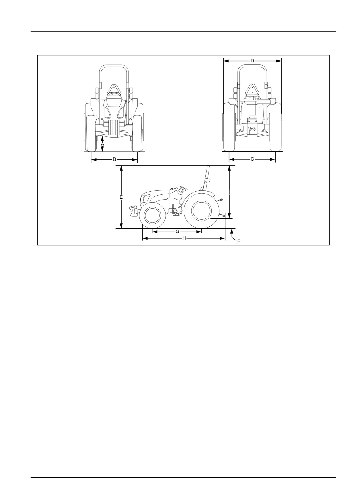
Tractor dimensions - General
GNIL14TR00583FA
1
NOTICE: The following dimensions are based on standard tractors fitted with tire sizes as shown. Allowance must
be given for tires of larger or smaller dimensions.
9-7
9 - SPECIFICATIONS
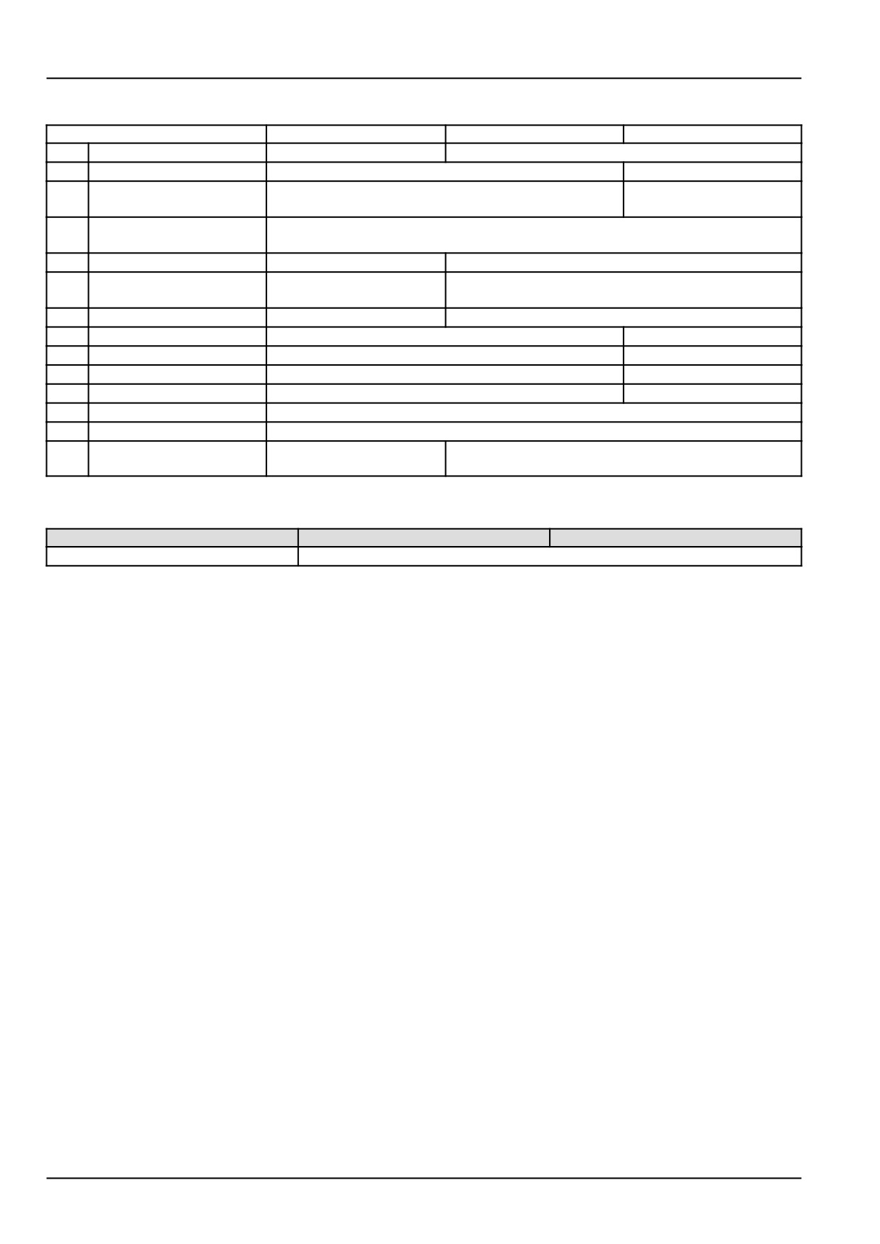
2WD/4WD Dimension
Dimension
A
Overall Width
1690.0 mm (66.5 in)
1714.0 mm (67.5 in)
B
Under front axle
495.0 mm (19.5 in)
405.0 mm (15.9 in)
C
Front Standard Track
1322.0 mm (52.0 in)
1385.0 mm (54.5 in)
Setting
D
Rear Standard Track
1336.0 mm (52.6 in)
Setting
E
To Top of Exhaust
2300.0 mm (90.6 in)
2317.0 mm (91.2 in)
F
Less Cab (top of
2450.0 mm (96.5 in)
2478.0 mm (97.6 in)
seat/ROPS)
G
Under Standard Drawbar
429.0 mm (16.9 in)
456.0 mm (18.0 in)
H
Weight carrier
285.0 mm (11.2 in)
175.0 mm (6.9 in)
Front weights
500.0 mm (19.7 in)
389.0 mm (15.3 in)
J
Wheel base
1970.0 mm (77.6 in)
1960.0 mm (77.2 in)
K
Overall Length
3290.0 mm (129.5 in)
3404.0 mm (134.0 in)
L
Rear Axle to top of ROPS
1795.0 mm (70.7 in)
M
Drawbar to Rear Axle
226.0 mm (8.9 in)
N
Ground to Top of ROPS
1927.0 mm (75.9 in)
1957.0 mm (77.0 in)
when Folded
Tractor total weight
Model
2WD
4WD
3000.0 kg (6613.9 lb)
9-8

10 - ACCESSORIES
10 - ACCESSORIES###_10_###
Front-end loader
GNIL14TR00581FA
1
Your tractor can, on request, be fitted for the front loader
The loader is controlled by joystick (2), installed in the cab
connection.
on the right-hand side of the driver's seat.
NOTE: For installation of the front loader and its opera-
The kit comprises:
tion, refer to the manual supplied by the manufacturer of
the loader.
(1) Support for loader connection.
(2) Joystick.
10-1
10 - ACCESSORIES
Control valve joystick - Overview
WARNING
WARNING
Escaping fluid!
Avoid injury and/or machine damage!
Do not connect or disconnect hydraulic quick
Before disconnecting the couplers, you must:
coupler under pressurized conditions. Make
-lower the connected attachments,
sure all hydraulic pressure is removed from
-stop the engine,
the system before connecting or disconnect-
-move the control levers forward and back-
ing hydraulic quick coupler.
ward to discharge pressure from the hydraulic
Failure to comply could result in death or se-
system.
rious injury.
Failure to comply could result in death or se-
W0095B
rious injury.
W0933A
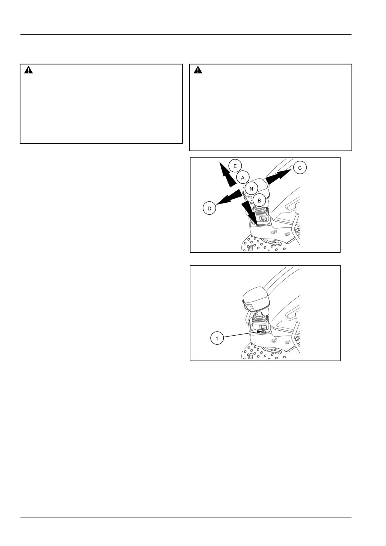
Joystick positions
(A) Lever forward - lowering function
(B) Lever backward - lifting function
(E) Lever completely forward - float function
(C) Lever to the right - lowering function
(D) Lever to the left - lifting function
Moving the joystick lever diagonally operates two con-
trol valves simultaneously. This function is useful when
working with loaders, fertiliser spreaders, combined seed
drills/fertiliser spreaders, etc.
GNIL14TR00566AA
1
Safety latch
To use the joystick, disengage the safety latch (1) by
pulling the safety latch out. When the joystick is not being
used, push the safety latch in to lock the joystick and to
prevent the joystick from being operated accidentally.
2
GNIL14TR00567AA
NOTE: Do not hold the joystick at either the extended
allowed to continue for long periods of time the oil will
or retracted position when the cylinder has reached the
overheat, which may lead to problems with hydraulic and
travel limit, as this would result in the system operating
drive line components.
at maximum pressure, thus opening the relief valve. If
10-2
11 - FORMS AND DECLARATIONS
11 - FORMS AND DECLARATIONS###_11_###
Pre-delivery report - Owner's copy
Check and adjust as required
Workmaster 50/60/70
Inoperative service checks
Safety items check
1.
Tire Pressure,
1.
ROPS Installed,
2.
Seat Belts Installed,
2.
Air Cleaner Element & Hose Connections
3.
PTO Shield Installed,
4.
SMV Emblem Installed,
5.
Safety Decals Installed,
3.
Radiator Coolant Level,
6.
Neutral Start Switches Operation,
7.
Park Brake & Latch Operation,
4.
Fan Belt Tension,
8.
Flashing Lights/Tail Lights Operation,
9.
Operator's Manual (present),
5.
Battery Cleanliness, Vent Openings,
Electrolyte Level, & Charge,
6.
Engine Oil Level,
Operative service checks
All operating checks are to be performed with tractor at
7.
Power Steering Reservoir
normal operating temperature.
Oil Level,
1.
Lights & Instruments for Proper Operation
8.
Transmission & Rear Axle Oil Level,
& Fuel Shut Down with Key Switch Off
9.
Hydraulic Lift Control Drop
2.
Fluid & Oil Leaks
Rate Adjustment (Response Control),
3.
Maximum No-load High & Idle
10.
Top Link (present),
Speed Adjustments,
11.
Brake Adjustment & Pedal Equalization
4.
PTO Engagement & Disengagement
4-8
12.
Rear Wheel Bolt Torque - 192 N·m (142 lb ft)
5.
Hydraulic System:
Selector Lever for Position Control -
13.
Front Wheel Bolt Torque - 123 N·m (91 lb ft)
14.
Front Wheel Toe-in,
15.
Fuel Level, 4-3
16.
Body Panels & Paint Condition, 6-1
17.
Seat Functions, 2-2
Dealer Representative's
Date
Signature
"I have been instructed in the operation, maintenance, and safety features of this machine as detailed in the
operator's manual."
Owner's Signature
Date
11-1
11 - FORMS AND DECLARATIONS
Pre-delivery report - Dealer's copy
Check and adjust as required
Workmaster 50/60/70
Inoperative service checks
Safety items check
1.
Tire Pressure,
1.
ROPS Installed,
2.
Seat Belts Installed,
2.
Air Cleaner Element & Hose Connections
3.
PTO Shield Installed,
4.
SMV Emblem Installed,
5.
Safety Decals Installed,
3.
Radiator Coolant Level,
6.
Neutral Start Switches Operation,
7.
Park Brake & Latch Operation,
4.
Fan Belt Tension,
8.
Flashing Lights/Tail Lights Operation,
9.
Operator's Manual (present),
5.
Battery Cleanliness, Vent Openings,
Electrolyte Level, & Charge,
6.
Engine Oil Level,
Operative service checks
All operating checks are to be performed with tractor at
7.
Power Steering Reservoir
normal operating temperature.
Oil Level,
1.
Lights & Instruments for Proper Operation
8.
Transmission & Rear Axle Oil Level,
& Fuel Shut Down with Key Switch Off
9.
Hydraulic Lift Control Drop
2.
Fluid & Oil Leaks
Rate Adjustment (Response Control),
3.
Maximum No-load High & Idle
10.
Top Link (present),
Speed Adjustments,
11.
Brake Adjustment & Pedal Equalization
4.
PTO Engagement & Disengagement
4-8
12.
Rear Wheel Bolt Torque - 192 N·m (142 lb ft)
5.
Hydraulic System:
Selector Lever for Position Control -
13.
Front Wheel Bolt Torque - 123 N·m (91 lb ft)
14.
Front Wheel Toe-in,
15.
Fuel Level, 4-3
16.
Body Panels & Paint Condition, 6-1
17.
Seat Functions, 2-2
Dealer Representative's
Date
Signature
"I have been instructed in the operation, maintenance, and safety features of this machine as detailed in the
operator's manual."
Owner's Signature
Date
11-2