New Holland Tractor Workmaster 50 / Workmaster 60 / Workmaster 70 / Tier 4B (final). SERVICE MANUAL - page 18
DTC 2D3-12-ECU internal failure - Software resets in DSM 1 [ECU]
180
DTC 2D4-04-ECU internal failure - ROM error [ECU]
181
DTC 2E1-02-Starter relay low side driver circuit open [ECU]
182
DTC 2E1-03-Starter relay low side driver circuit shorted to battery [ECU]
184
DTC 2E1-04-Starter relay low side driver circuit shorted to ground [ECU]
186
DTC 2E1-12-Starter relay low side ECU driver circuit over temperature [ECU]
188
DTC 32B-02-Glow plug control circuits open [ECU]
190
DTC 32B-03-Glow plug control circuits shorted to battery [ECU]
192
DTC 32B-04-Glow plug control circuits shorted to ground [ECU]
194
DTC 32B-12-Glow plug control circuits shorted [ECU]
196
DTC 359-04-Fuel metering unit is shorted to ground at the low side [ECU]
198
DTC 35A-03-Error in comparing energizing time to maximum value for injector in cylinder 2 [ECU] . . 200
DTC 35A-04-Error in comparing energizing time to minimum value for injector in cylinder 2 [ECU] . . . 201
DTC 35D-03-PMCat Inducement warning [ECU]
202
DTC 37F-12-Missing adjustment value programming for injector in cylinder 3 [ECU]
203
DTC 3C8-02-CAN communication failure between vehicle controller and ECU controller - TSC1_VE mes-
sage [ECU]
204
DTC
3D4-02-ECU internal failure - ECU shutdown test failure [ECU]
206
DTC
3D4-03-ECU internal failure - Wrong set response time [ECU]
207
DTC
3D4-04-ECU internal failure - SPI errors during MoCSOP execution [ECU]
208
DTC
3D4-12-ECU internal failure - Loss of synchronization to MM from CPU [ECU]
209
DTC
3E3-00-ECU internal failure - Fuel injection energizing time is not plausible [ECU]
210
DTC
3E3-01-ECU internal failure - Fuel injection energizing phase is not plausible [ECU]
211
DTC
3E3-02-Fuel injection correction has exceeded a minimum limit [ECU]
212
DTC
3E3-03-ECU internal failure - Injection quantity correction [ECU]
213
DTC
3E3-04-ECU internal failure - Rail pressure plausibility [ECU]
214
DTC
3E3-12-ECU internal failure - Torque request comparison [ECU]
215
DTC
3F6-03-DOC inlet temperature sensor voltage is higher than expected [ECU]
216
DTC
3F6-04-DOC inlet temperature sensor voltage is lower than expected [ECU]
218
DTC
426-03-Level 2 Monitoring : Reported Overvoltage of Supply [ECU]
220
DTC
426-04-Level 2 Monitoring : Reported Under Voltage of Supply [ECU]
221
DTC
435-12-Rail pressure sensor value is intermittent [ECU]
222
DTC
455-03-High pressure pump fuel delivery quantity at low idle is too high [ECU]
224
DTC
459-03-Fuel metering unit intermittent electrical connection failure [ECU]
225
DTC
45A-03-Error in comparing energizing time to maximum value for injector in cylinder 3 [ECU] . . 227
DTC
45A-04-Error in comparing energizing time to minimum value for injector in cylinder 3 [ECU] . . . 228
DTC
48D-02-Throttle valve actuator control circuit open [ECU]
229
DTC
48D-03-Throttle valve actuator control circuit over current [ECU]
231
DTC
48D-12-Throttle valve actuator control circuit over temperature [ECU]
233
DTC
4D4-03-ECU internal failure - Overvoltage monitoring error [ECU]
235
DTC
4D4-04-ECU internal failure - Undervoltage monitoring error [ECU]
236
DTC
4E3-03-ECU internal failure - Post injection quantity [ECU]
237
5
DTC 4E3-04-Level 2 Monitoring : Diagnosis fault check to report the error to demand for an ICO due to
an error in the PoI2 shut-off [ECU]
238
DTC 4E3-12-Level 2 Monitoring : Diagnosis fault check to report the error to demand for an ICO due to
an error in the PoI3 efficiency factor [ECU]
239
DTC 52C-01-Glow Control Unit (GCU) data error [ECU]
240
DTC 532-03-Engine coolant temperature has exceeded the warning threshold [ECU]
242
DTC 535-03-Maximum rail pressure exceeded [ECU]
243
DTC 54C-03-Engine over speed condition detected [ECU]
244
DTC 559-12-Fuel metering unit has an over-temperature error [ECU]
245
DTC 58C-03-Throttle valve actuator will not open to commanded position [ECU]
247
DTC 58C-04-Throttle valve actuator will not close to commanded position [ECU]
248
DTC 58D-03-Throttle valve actuator control circuit high side shorted to battery [ECU]
249
DTC 58D-04-Throttle valve actuator control circuit high side shorted to ground [ECU]
251
DTC 5D2-03-ECU internal failure - EEPROM memory failure [ECU]
253
DTC 5D4-02-ECU internal failure - WDA is not working correctly [ECU]
254
DTC 5D4-03-ECU internal failure - Alarm task period error [ECU]
255
DTC 5D4-04-ECU internal failure - Positive test failed [ECU]
256
DTC 5D4-12-ECU internal failure - Timeout in the shut off path test error [ECU]
257
DTC 5E3-03-ECU internal failure - Torque request due to fuel pressure exceeds maximum torque limit
[ECU]
258
DTC 5E3-04-ECU internal failure - Torque request due to air control exceeds maximum torque limit
[ECU]
259
DTC 5E3-12-ECU internal failure - Torque request exceeds maximum torque limit [ECU]
260
DTC 601-02-Lambda sensor nernst cell open circuit [ECU]
261
DTC 602-02-Lambda sensor pump current open circuit [ECU]
263
DTC 605-03-Lambda sensor O2 value above maximum threshold [ECU]
265
DTC 606-02-Lambda sensor virtual ground open circuit [ECU]
267
DTC 607-03-Lambda sensor O2 calibrator too high error [ECU]
269
DTC 607-04-Lambda sensor O2 calibrator too low error [ECU]
270
DTC 609-02-ECU internal failure - SPI chip error configuration [ECU]
271
DTC 60A-04-Lambda sensor heater battery voltage too low [ECU]
272
DTC 60B-03-Lambda sensor cell circuits short circuit to battery [ECU]
274
DTC 60B-04-Lambda sensor cell circuits short circuit to ground [ECU]
276
DTC 60C-03-Lambda sensor estimated temperature higher than threshold [ECU]
278
DTC 60C-04-Lambda sensor estimated temperature lower than threshold [ECU]
280
DTC 68D-03-Throttle valve actuator control circuit low side shorted to battery [ECU]
282
DTC 68D-04-Throttle valve actuator control circuit low side shorted to ground [ECU]
284
DTC 6D4-02-ECU internal failure - 'WDA active' reported due to errors in query/response communication
[ECU]
286
DTC 6D4-03-ECU internal failure - 'ABE active' reported due to overvoltage detection [ECU]
287
DTC 6D4-04-ECU internal failure - 'ABE active' reported due to undervoltage detection [ECU]
288
DTC 6D4-12-ECU internal failure - 'WDA/ABE active' reported [ECU]
289
DTC 72C-00-Glow plug 1 control circuit shorted to ground [ECU]
290
DTC 72C-01-Glow plug 3 control circuit shorted to ground [ECU]
292
6
DTC 72C-03-Glow plug 2 control circuit shorted to ground [ECU]
294
DTC 78B-03-Throttle valve actuator position sensor voltage is higher than expected [ECU]
296
DTC 78B-04-Throttle valve actuator position sensor voltage is lower than expected [ECU]
298
DTC 78D-03-Throttle valve actuator control circuit over load [ECU]
300
DTC 78D-04-Throttle valve actuator control circuit supply voltage too low [ECU]
302
DTC 7BA-02-Timeout Error of CAN-Receive-Frame CM1BC [ECU]
303
7
Electrical systems - FAULT CODES
DTC 11C-02-Water in fuel sensor or sensor circuit failure
Control Module : ECU
NOTE: This fault code is for the Water in Fuel switch with black connector housing.
Context:
The water in fuel switch S-9102 provides a diagnostic self-test signal (less than 3.9 V for 2.5 s +/- 20%) at key-ON.
If the Engine Control Unit (ECU) A-9000 does not sense the diagnostic self-test signal, this fault will occur and there
will be no monitoring of water content in the fuel supply.
Cause:
The ECU A-9000 has not received an acceptable water in fuel switch S-9102 self-test signal.
Possible failure modes:
1. Faulty water in fuel switch S-9102 circuit wiring, damaged.
2. Faulty water in fuel switch S-9102, internal failure.
3. Faulty ECU A-9000, software.
Solution:
1.
Verify this fault code is still present and in an active state.
Use the Easy Engine software provided on the Electronic Service Tool (EST) to check the fault status.
A. If the fault is still present and active, continue with Step 2.
B. If the fault is no longer present or is in an inactive state, Continue with Step 7.
2.
Use the EST to check for related faults that may have caused this fault to occur.
A. If any other faults that may have caused this fault to occur are active, resolve those faults first and then return
to this fault.
B. If no other faults are active,continue with Step 3.
3.
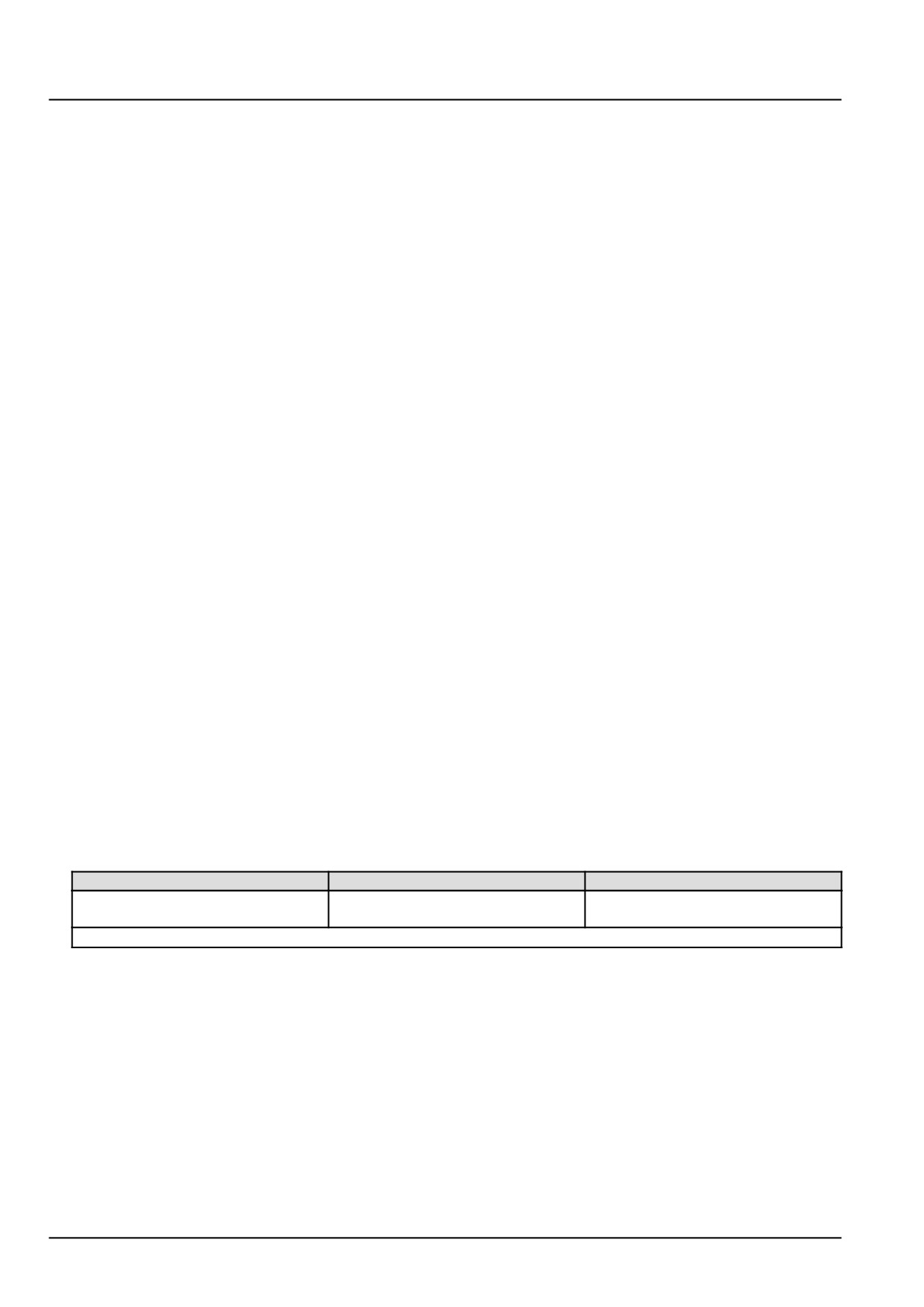
Check the water in fuel switch S-9102 for the initial self-test voltage pulse.
Carefully back probe the water in fuel switch S-9102 at connector X-9125.
With the help of an assistant, use a multimeter to perform the following test at Key-ON:
From
To
Value
X-9125 pin 1
Chassis ground
There should be less than 3.9 V for
2.5 s +/- 20%.
NOTE: The signal line should switch to battery voltage after the self-test period.
A. If the self-test is successful, continue with Step 4.
B. If the self-test is not successful, the water in fuel switch S-9102 has failed internally. Replace the switch.
4.
Check for open, short and grounded circuit conditions in the water in fuel switch S-9102 circuit.
Disconnect the water in fuel switch S-9102 at connector X-9125.
Disconnect the vehicle (VE) harness from the ECU A-9000 at connector X-9102.
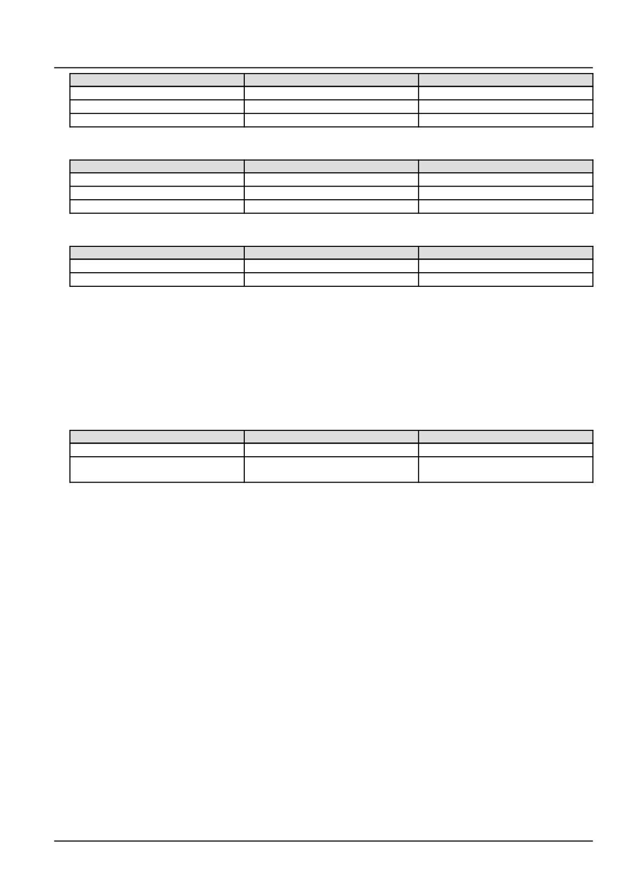
With the key switch in the OFF position, use a multimeter to perform the following tests, on the vehicle (VE) harness
from :
8
Electrical systems - FAULT CODES
From
To
Value
X-9125 pin 1
X-9102 pin K88
There should be continuity.
X-9125 pin 2
Chassis ground
There should be continuity.
X-9125 pin 3
X-9102 pin K01
There should be continuity.
Then use the multimeter to perform the following tests, on the vehicle (VE) harness from :
From
To
Value
X-9125 pin 1
X-9125 pin 2
There should be no continuity
X-9125 pin 1
X-9125 pin 3
There should be no continuity
X-9125 pin 2
X-9125 pin 3
There should be no continuity
Then use the multimeter to perform the following tests, on the vehicle (VE) harness from :
From
To
Value
X-9125 pin 1
Chassis ground
There should be no continuity
X-9125 pin 3
Chassis ground
There should be no continuity
A. If the results are not as expected for any of the wiring tests listed above, there is an open, short or grounded
circuit condition in the vehicle harness (VE) wiring. Use the appropriate vehicle service manual and schematics
to diagnose and repair the wiring.
B. If the results are as expected in all of the wiring tests listed above, the wiring is ok. Leave connectors X-9102
and X-9125 disconnected and continue with Step 5.
5.
Check for key switch voltage supply to water in fuel switch S-9102.
With the key switch in an ON position, use a multimeter to perform the following test, on the vehicle (VE) harness
side from :
From
To
Value
X-9125 pin 3
Chassis ground
There should be key switch voltage.
X-9125 pin 1
Chassis ground
There should be no key switch
voltage.
A. If there is key switch voltage present in the first check and not present in the second check, continue with Step
6.
B. If key switch voltage is not present in the first check or present in the second check, use the appropriate vehicle
service manual and schematics to diagnose and repair the wiring.
6.
Replace the water in fuel switch S-9102, then check to see if this fault has been resolved.
A. If the fault is resolved, return the machine to service.
B. If the fault is not resolved, check the ECU A-9000 for the appropriate software and re-flash, if necessary.
7.
Visually inspect the relevant harnesses and connectors for damage, bent or dislocated pins, corroded terminals,
or broken wires. Verify that the connectors are fully installed. Flex the harnesses involved to reveal intermittent
breaks or shorts in the wiring concerned. Operate the machine while you monitor the display.
A. If you find damage or the display indicates other than normal readings, then repair the damage discovered
during the inspection or locate and repair the other than normal display condition and verify that the error has
been resolved.
B. If you do not find damage and the display indicates only normal readings, then erase the fault code and continue
operation.
Wiring harnesses - Electrical schematic sheet 02 - Engine Control Unit (ECU) power and after treatment
system (engine schematics) (55.100.DP-C.20.E.02)
9
Electrical systems - FAULT CODES
DTC 11C-03-Water in fuel detected or water in fuel circuit failure
Control Module : ECU
NOTE: This fault code is for the Water in Fuel switch with black connector housing.
Context:
The Engine Control Unit (ECU) A-9000 monitors the voltage output from the water in fuel switch S-9102 to determine
if water is present in the fuel supply. If water is detected in the fuel, warnings will be displayed to alert the operator
of potential engine damage if operation continues. High voltage signal from the water in fuel switch S-9102 indicates
water present.
Cause:
This fault code is displayed to warn the operator that the Engine Control Unit (ECU) A-9000 has detected excess
water in the fuel system or a fault in the water in fuel switch circuit.
Possible failure modes:
1. Excess water in the fuel supply.
2. Faulty water in fuel switch S-9102, wiring or internal (mechanical and/or electrical) failure.
3. Faulty ECU A-9000, software.
Solution:
1.
Verify this fault code is still present and in an active state.
Use the Easy Engine software provided on the Electronic Service Tool (EST) to check the fault status.
A. If the fault is still present and active, continue with Step 2.
B. If the fault is no longer present or is in an inactive state, Continue with Step 7.
2.
Check fuel for water contamination.
A. If there is water contamination, continue with Step 3.
B. If there is no water contamination, Continue with Step 4.
3.
Verify proper water in fuel switch S-9102 operation.
Purge fuel supply system, replace fuel filter(s) and refill with fuel that is free of water contamination.
Start and run engine for 5 minutes.
Check for code to return to active status.
A. If code returns in an active status, replace water in fuel switch S-9102.
B. If code remains inactive, return the machine to service.
4.
Check for open, short and grounded circuit conditions in the water in fuel switch S-9102 circuit.
Disconnect the water in fuel switch S-9102 at connector X-9125.
Disconnect the vehicle harness (VE) from the ECU A-9000 at connector X-9102.
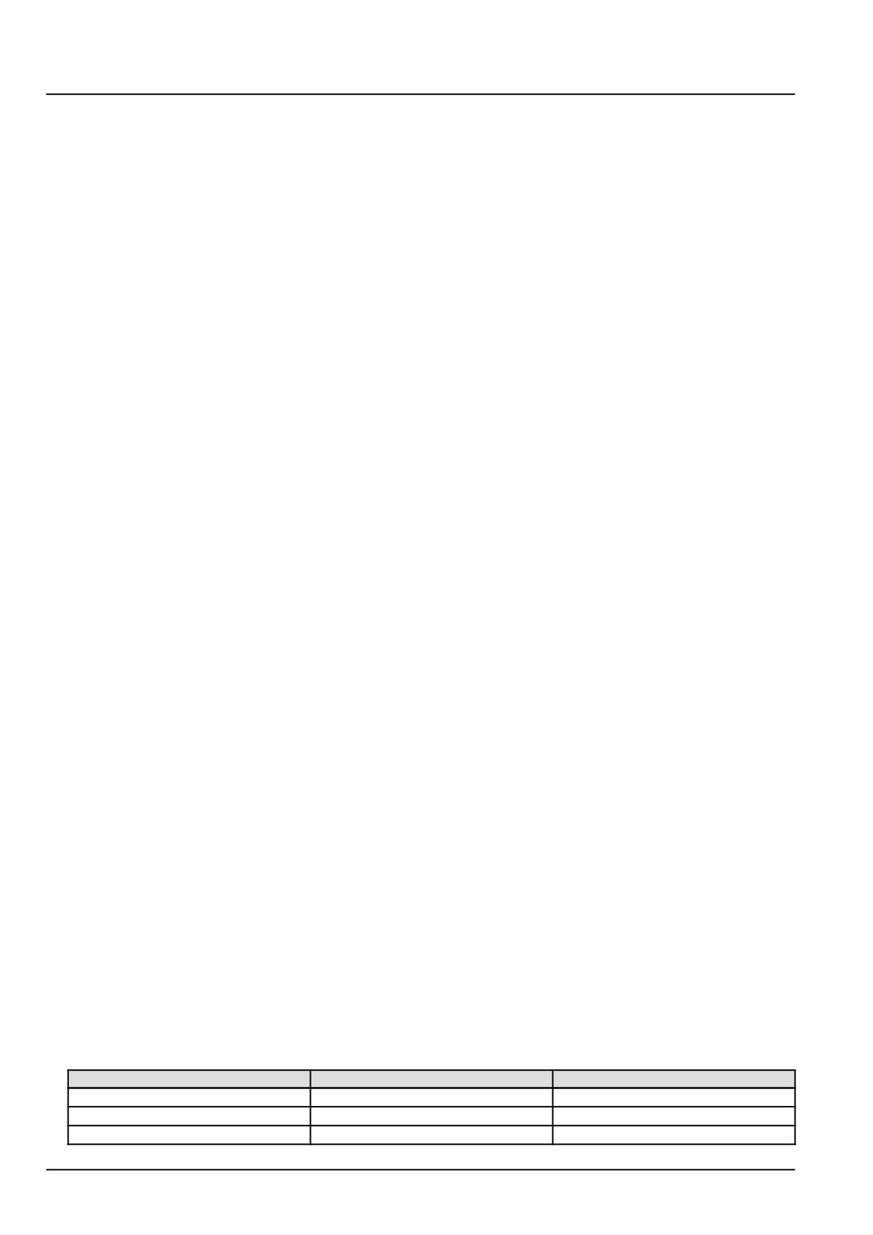
With the key switch in the OFF position, use a multimeter to perform the following tests, on the vehicle (VE) harness
from :
From
To
Value
X-9125 pin 1
X-9102 pin K88
There should be continuity.
X-9125 pin 2
Chassis ground
There should be continuity.
X-9125 pin 3
X-9102 pin K01
There should be continuity.
10
Electrical systems - FAULT CODES
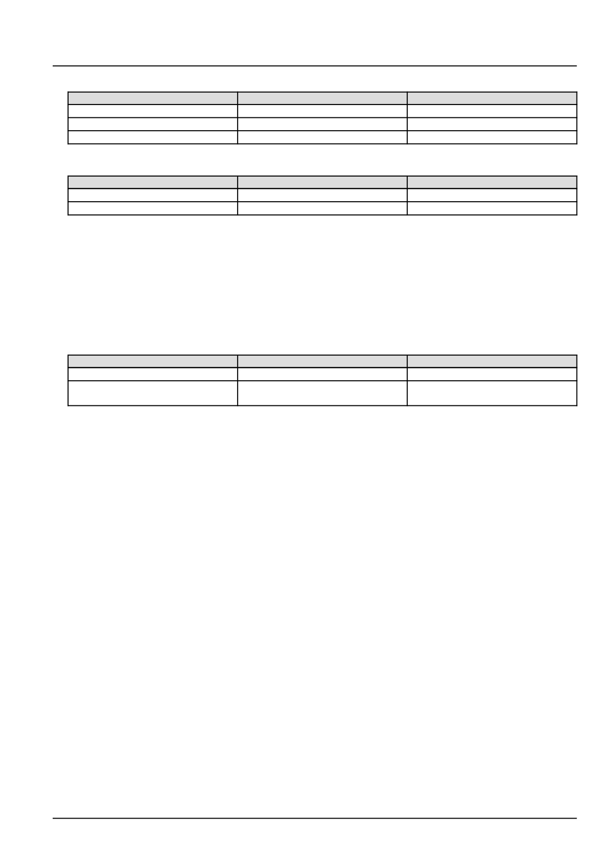
Then use the multimeter to perform the following tests, on the vehicle (VE) harness from :
From
To
Value
X-9125 pin 1
X-9125 pin 2
There should be no continuity
X-9125 pin 1
X-9125 pin 3
There should be no continuity
X-9125 pin 2
X-9125 pin 3
There should be no continuity
Then use the multimeter to perform the following tests, on the vehicle (VE) harness from :
From
To
Value
X-9125 pin 1
Chassis ground
There should be no continuity
X-9125 pin 3
Chassis ground
There should be no continuity
A. If the results are not as expected for any of the wiring tests listed above, there is an open, short or grounded
circuit condition in the vehicle harness (VE) wiring. Use the appropriate vehicle service manual and schematics
to diagnose and repair the wiring.
B. If the results are as expected in all of the wiring tests listed above, the wiring is ok. Leave connectors X-9102
and X-9125 disconnected and continue with Step 5.
5.
Check for key switch voltage supply to water in fuel switch S-9102.
With the key switch in an ON position, use a multimeter to perform the following test, on the vehicle (VE) harness
side from :
From
To
Value
X-9125 pin 3
Chassis ground
There should be key switch voltage.
X-9125 pin 1
Chassis ground
There should be no key switch
voltage.
A. If there is key switch voltage present in the first check and not present in the second check, continue with Step
6.
B. If key switch voltage is not present in the first check or present in the second check, use the appropriate vehicle
service manual and schematics to diagnose and repair the wiring.
6.
Replace the water in fuel switch S-9102, then check to see if this fault has been resolved.
A. If the fault is resolved, return the machine to service.
B. If the fault is not resolved, check the ECU A-9000 for the appropriate software and re-flash, if necessary.
7.
Visually inspect the relevant harnesses and connectors for damage, bent or dislocated pins, corroded terminals,
or broken wires. Verify that the connectors are fully installed. Flex the harnesses involved to reveal intermittent
breaks or shorts in the wiring concerned. Operate the machine while you monitor the display.
A. If you find damage or the display indicates other than normal readings, then repair the damage discovered
during the inspection or locate and repair the other than normal display condition and verify that the error has
been resolved.
B. If you do not find damage and the display indicates only normal readings, then erase the fault code and continue
operation.
Wiring harnesses - Electrical schematic sheet 02 - Engine Control Unit (ECU) power and after treatment
system (engine schematics) (55.100.DP-C.20.E.02)
11
Electrical systems - FAULT CODES
DTC 131-03-Engine coolant temperature sensor voltage is higher
than expected
Control Module : ECU
Context:
The Engine Control Unit (ECU) A-9000 monitors the engine coolant temperature sensor B-9003 signal circuit. If the
ECU A-9000 determines that voltage is higher than expected in the engine coolant temperature sensor B-9003 signal
circuit, this fault will occur. If this fault is active, the ECU A-9000 will set the engine coolant temperature value to a
fixed replacement value of 89.96 °C (193.93 °F).
Cause:
The engine coolant temperature sensor B-9003 signal voltage is greater than 4.93 V.
Possible failure modes:
1. Faulty engine coolant temperature sensor B-9003, short to a voltage source.
2. Faulty engine coolant temperature sensor B-9003, internal failure.
3. Faulty ECU A-9000, software.
Solution:
1.
Verify fault is present and active.
Use the Electronic Service Tool (EST) to check the status of this fault.
A. If the fault is present and active, continue with Step 2.
B. If the fault is no longer present or in an inactive state, the fault may be intermittent and not currently active.
Continue with Step 6.
2.
Check the coolant temperature sensor B-9003 wiring for a short circuit.
Disconnect the engine harness (EN) from the coolant temperature sensor B-9003 at connector X-9006.
With the key in the OFF position, use a multimeter to perform the following voltage check on the engine harness
side:
From
To
Value
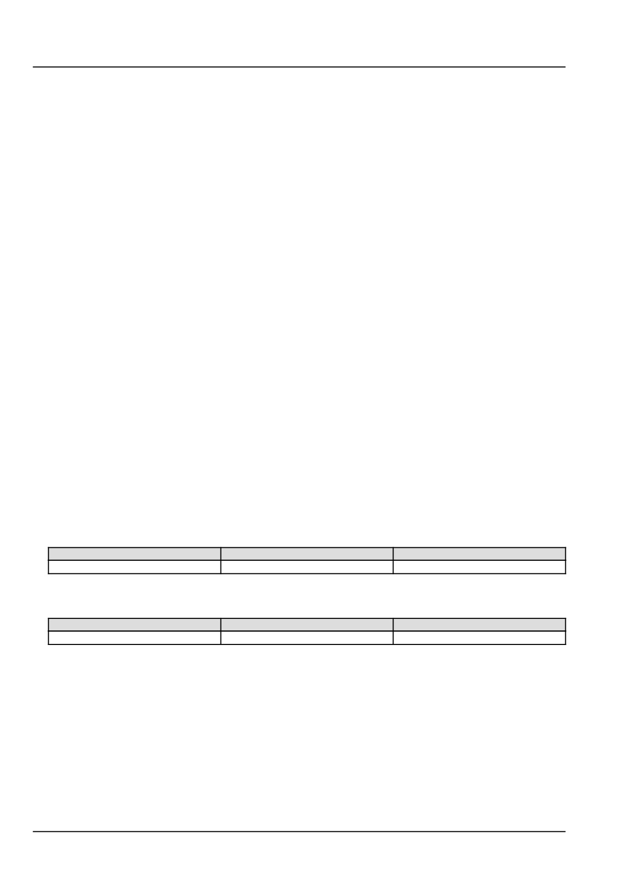
X-9006 pin 1
Chassis ground
There should be no voltage.
With the key in the ON position, use a multimeter to perform the following voltage check on the engine harness
side:
From
To
Value
X-9006 pin 1
Chassis ground
There should be less than 5.5 V
A. If the specified values are not measured, there is a short to a voltage source in the coolant temperature sensor
B-9003 wiring. Use the appropriate service manual, if necessary, to locate and repair the shorted conductor.
B. If the specified values are not measured, leave connector X-9006 disconnected and continue to Step 3.
3.
Check the coolant temperature sensor B-9003 engine harness (EN) wiring for a short circuit.
Disconnect the engine harness (EN) from the ECU A-9000 at connector X-9001.
With the key in the OFF position, use a multimeter to perform the following continuity check on the engine harness
(EN) side:
12
Electrical systems - FAULT CODES
From
To
Value
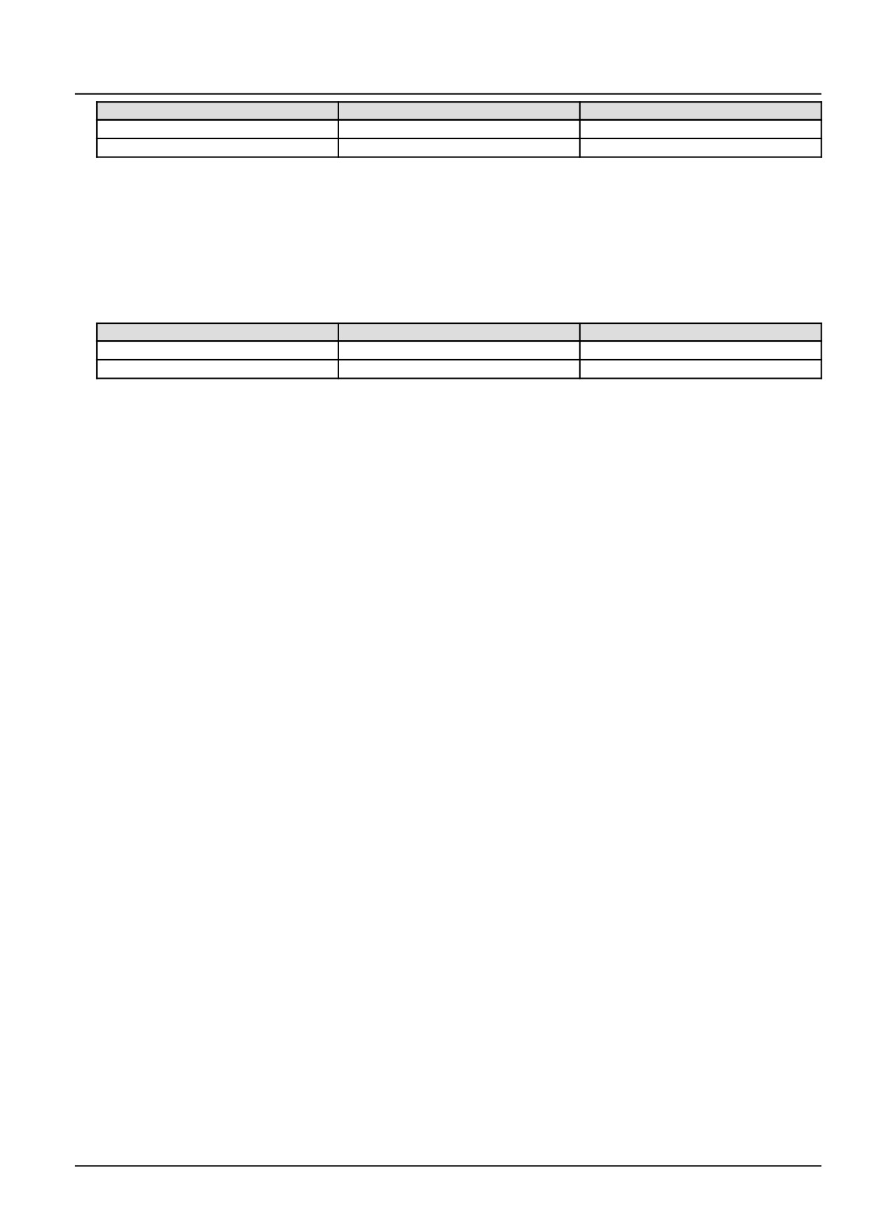
X-9006 pin 1
X-9001 pin A57
There should be continuity.
X-9006 pin 2
X-9001 pin A58
There should be continuity.
A. If there is continuity, leave the connector X-9001 disconnected and continue to Step 4.
B. If there is no continuity, there is an open circuit in the coolant temperature sensor B-9003 wiring. Locate and
repair the broken conductor.
4.
Check the coolant temperature sensor B-9003 engine harness (EN) wiring for a short circuit.
With the key in the OFF position, use a multimeter to perform the following continuity check from the engine har-
ness (EN) side:
From
To
Value
X-9001 pin A57
All pins in connector X-9001
There should be no continuity.
X-9001 pin A58
All pins in connector X-9001
There should be no continuity.
A. If there is no continuity, leave connector X-9006 disconnected and continue to Step 5.
B. If there is continuity, there is a short circuit condition in the wiring. Locate and repair the shorted conductor.
5.
Replace the engine coolant temperature sensor B-9003.
Use the EST to verify the status of the this fault.
A. If the fault is no longer active, return the machine to service.
B. If the fault is still active, check the ECU A-9000 for the appropriate software and re-flash, if necessary.
6.
Visually inspect the relevant harnesses and connectors for damage, bent or dislocated pins, corroded terminals,
or broken wires. Verify that the connectors are fully installed. Flex the harnesses involved to reveal intermittent
breaks or shorts in the wiring concerned. Operate the machine while you monitor the display.
A. If you find damage or the display indicates other than normal display readings, then repair the damage discov-
ered during the inspection or locate and repair the other than normal display condition and verify that the error
has been resolved.
B. If you do not find damage and the display indicates only normal readings, then erase the fault code and continue
operation.
Wiring harnesses - Electrical schematic sheet 03 - Engine sensors and fuel injection (engine schematics)
(55.100.DP-C.20.E.03)
13
Electrical systems - FAULT CODES
DTC 131-04-Engine coolant temperature sensor voltage is lower
than expected
Control Module : ECU
Context:
The Engine Control Unit (ECU) A-9000 monitors the engine coolant temperature sensor B-9003 signal circuit. If the
ECU A-9000 determines that voltage is lower than expected in the engine coolant temperature sensor B-9003 signal
circuit, this fault will occur. If this fault is active, the ECU A-9000 will set the engine coolant temperature value to a
fixed replacement value of 89.96 °C (193.93 °F).
Cause:
The engine coolant temperature sensor B-9003 signal voltage is less than 198.00 mV.
Possible failure modes:
1. Faulty engine coolant temperature sensor B-9003 wiring, short to ground condition.
2. Faulty engine coolant temperature sensor B-9003, internal failure.
3. Faulty ECU A-9000, software.
Solution:
1.
Verify fault is present and active.
Use the Electronic Service Tool (EST) to check the status of this fault.
A. If the fault is present and active, continue with Step 2.
B. If the fault is no longer present or in an inactive state, the fault may be intermittent and not currently active.
Continue with Step 5.
2.
Check the coolant temperature sensor B-9003 engine harness (EN) wiring for a short to ground condition.
Disconnect the engine harness (EN) from the coolant temperature sensor B-9003 at connector X-9006.
With the key in the OFF position, use a multimeter to perform the following continuity check on the engine harness
(EN) side:
To
From
Value
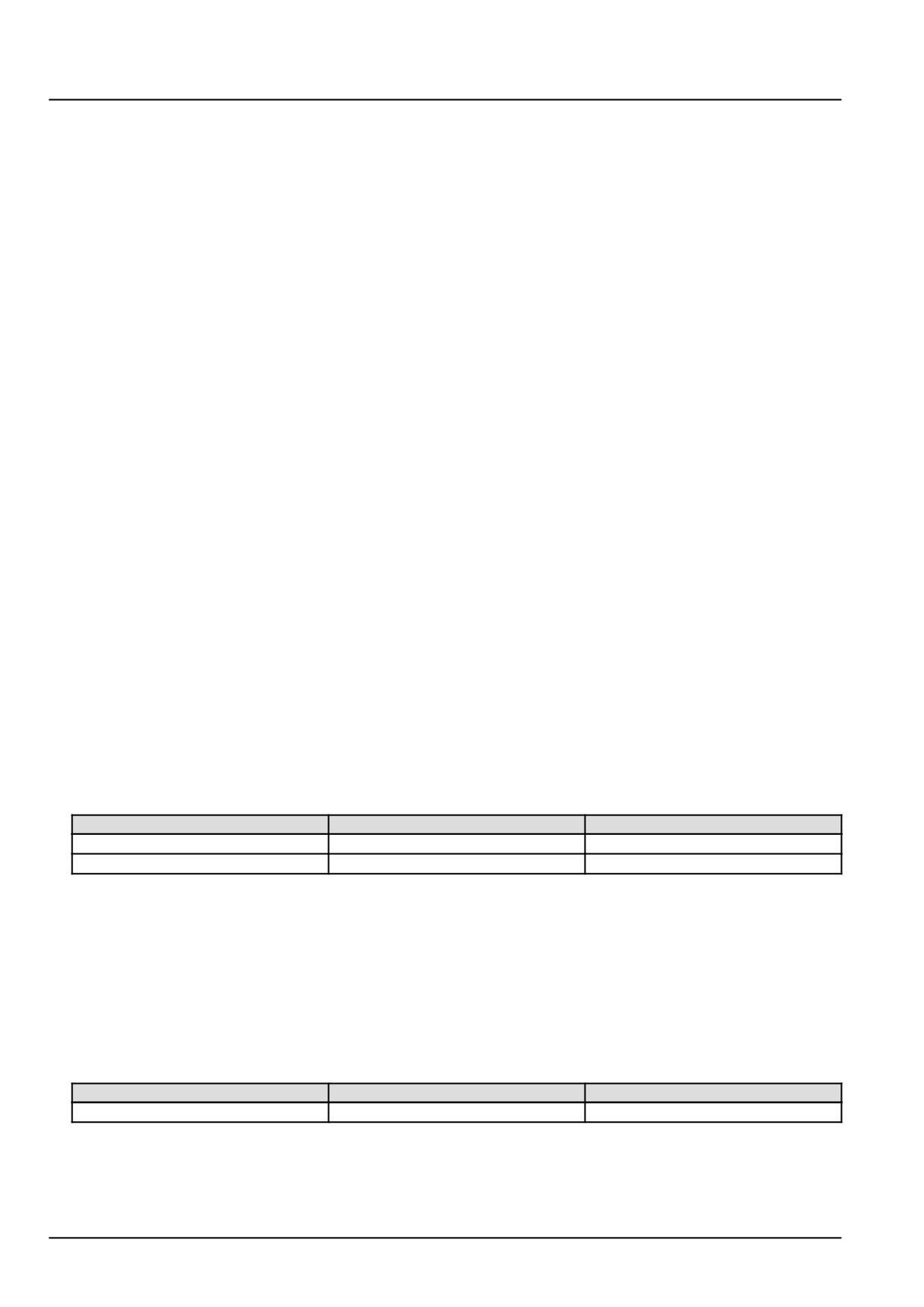
X-9006 pin 1
X-9006 pin 2
There should be no continuity.
X-9006 pin 1
Chassis ground
There should be no continuity.
A. If there is no continuity, leave connector X-9006 disconnected and continue to Step 3.
B. If there is continuity, there is a short to ground condition in the coolant temperature sensor B-9003 engine
harness (EN) wiring. Locate and repair the shorted conductor.
3.
Check the coolant temperature sensor B-9003 engine harness (EN) wiring for a short to ground condition.
Disconnect the engine harness (EN) from the ECU A-9000 at connector X-9001.
With the key in the OFF position, use a multimeter to perform the following continuity check on the engine harness
(EN) side:
From
To
Value
X-9001 pin A57
All pins in connector X-9001
There should be no continuity.
A. If there is no continuity, leave connector X-9006 disconnected and continue to Step 4.
B. If there is continuity, there is a short circuit in the coolant temperature sensor B-9003 engine harness (EN)
wiring. Locate and repair the shorted or broken conductor.
14
Electrical systems - FAULT CODES
4. Replace the engine coolant temperature sensor B-9003.
Use the EST to verify the status of the this fault.
A. If the fault is no longer active, return the machine to service.
B. If the fault is still active, check the ECU A-9000 for the appropriate software and re-flash, if necessary.
5. Visually inspect the relevant harnesses and connectors for damage, bent or dislocated pins, corroded terminals,
or broken wires. Verify that the connectors are fully installed. Flex the harnesses involved to reveal intermittent
breaks or shorts in the wiring concerned. Operate the machine while you monitor the display.
A. If you find damage or the display indicates other than normal display readings, then repair the damage discov-
ered during the inspection or locate and repair the other than normal display condition and verify that the error
has been resolved.
B. If you do not find damage and the display indicates only normal readings, then erase the fault code and continue
operation.
Wiring harnesses - Electrical schematic sheet 03 - Engine sensors and fuel injection (engine schematics)
(55.100.DP-C.20.E.03)
15
Electrical systems - FAULT CODES
DTC 133-03-Intake manifold temperature sensor voltage is higher
than expected
Control Module : ECU
Context:
The Engine Control Unit (ECU) A-9000 monitors the intake manifold temperature sensor B-9001 signal circuit. If the
ECU A-9000 determines that the intake manifold temperature sensor B-9001 signal circuit voltage is greater than
4.94 V, this fault will occur.
Cause:
The ECU A-9000 has determined that the intake manifold temperature sensor B-9001 signal circuit voltage is greater
than 4.94 V
Possible failure modes:
1. Faulty intake manifold temperature sensor B-9001 wiring, short to a voltage source.
2. Faulty intake manifold temperature sensor B-9001 wiring, open circuit.
3. Faulty intake manifold temperature sensor B-9001, internal failure.
4. Faulty ECU A-9000, software.
Solution:
1.
Verify fault is present and active.
Use the Electronic Service Tool (EST) to check the status of this fault.
A. If the fault is present and active, continue with Step 2.
B. If the fault is no longer present or in an inactive state, the fault may be intermittent and not currently active.
Continue with Step 6.
2.
Check the intake manifold temperature sensor B-9001 wiring for a short to battery condition.
Disconnect the engine harness (EN) from the intake manifold temperature sensor B-9001 at connector X-9003.
With the key in the OFF position, use a multimeter to perform the following voltage check on the engine harness
(EN) side :
From
To
Value
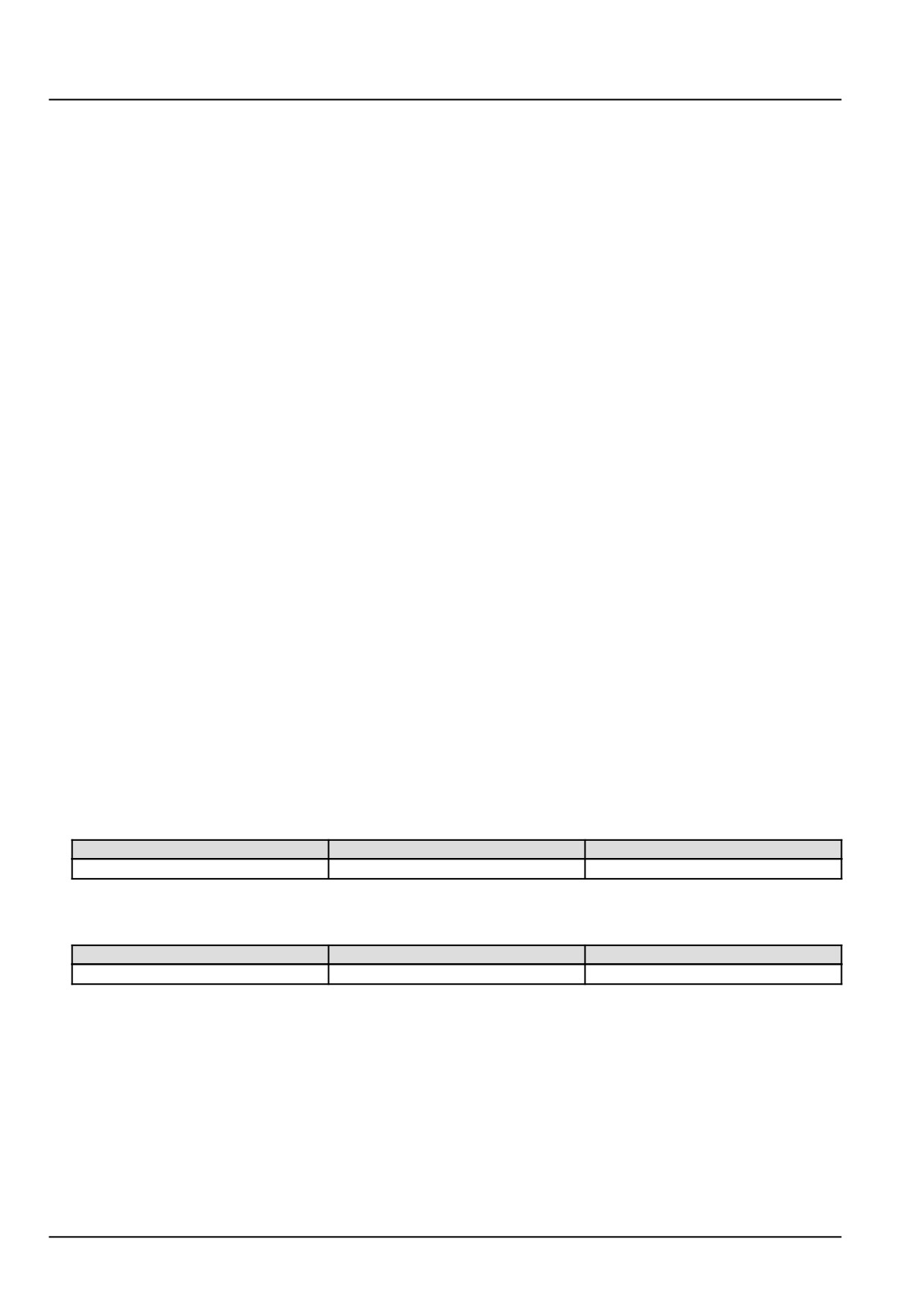
X-9003 pin 2
Chassis ground
There should be no voltage.
With the key in the ON position, use a multimeter to perform the following voltage check at the engine harness
(EN) side of the connector from :
From
To
Value
X-9003 pin 2
Chassis ground
There should be less than 5.5 V.
A. If the specified values are not measured, there is a short to a voltage source in the intake manifold temperature
sensor B-9001 signal circuit. Use the appropriate service manual, if necessary, to locate and repair the shorted
conductor.
B. If the specified values are measured, leave connector X-9003 disconnected and continue to Step 3.
3.
Check the intake manifold temperature sensor B-9001 wiring for an open circuit condition.
Disconnect the engine harness (EN) from the ECU A-9000 at connector X-9001.
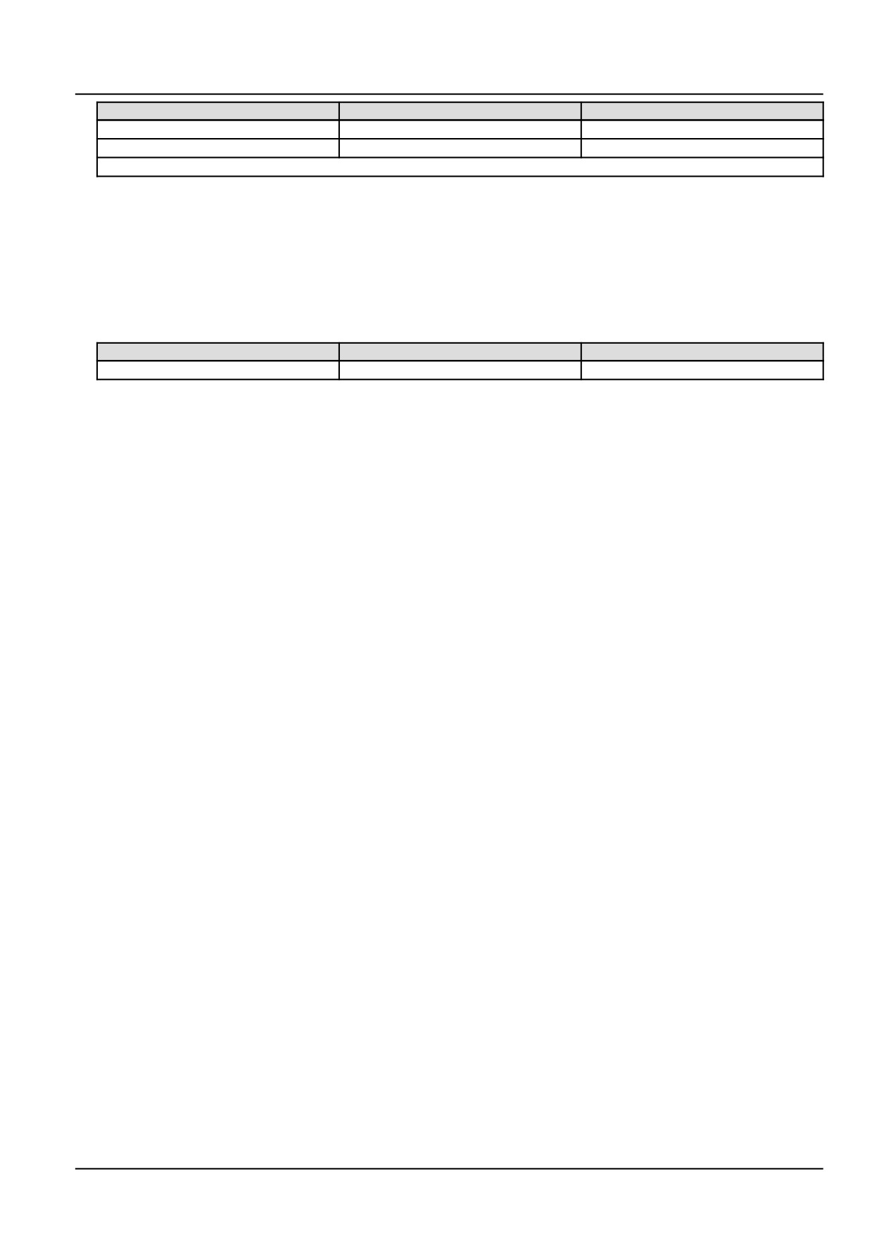
With the key in the OFF position, use a multimeter to perform the following continuity check for an open circuit on
the engine harness side:
16
Electrical systems - FAULT CODES
From
To
Value
X-9003 pin 2
X-9001 pin A55
There should be continuity.
X-9003 pin 3
X-9001 pin A10
There should be continuity.
NOTE: Wiggle the harness during the check to promote an intermittent electrical connection.
A. If there is no continuity, there is an open circuit in the intake manifold temperature sensor B-9001 wiring. Locate
and repair the broken conductor.
B. If there is continuity, leave connector X-9003 and X-9001 disconnected and continue to Step 4.
4.
Check the intake manifold temperature sensor B-9001 engine harness (EN) wiring for a short circuit.
With the key in the OFF position, use a multimeter to perform the following continuity check for a short circuit on
the engine harness (EN) side:
From
To
Value
X-9001 pin A55
All pins in connector X-9001
There should be no continuity.
A. If there is continuity, there is a short circuit in the intake manifold temperature sensor B-9001 in the engine
harness (EN) wiring. Locate and repair the shorted conductor.
B. If there no continuity, leave connector X-9003 disconnected and continue to Step 5.
5.
Replace the intake manifold temperature sensor B-9001.
Use the Electronic Service Tool (EST) to check the status of this fault.
A. If the fault is no longer active, return the machine to service.
B. If the fault is still active, check the ECU A-9000 for the appropriate software and re-flash, if necessary.
6.
Visually inspect the relevant harnesses and connectors for damage, bent or dislocated pins, corroded terminals,
or broken wires. Verify that the connectors are fully installed. Flex the harnesses involved to reveal intermittent
breaks or shorts in the wiring concerned. Operate the machine while you monitor the display.
A. If you find damage or the display indicates other than normal display readings, then repair the damage discov-
ered during the inspection or locate and repair the other than normal display condition and verify that the error
has been resolved.
B. If you do not find damage and the display indicates only normal readings, then erase the fault code and continue
operation.
Wiring harnesses - Electrical schematic sheet 03 - Engine sensors and fuel injection (engine schematics)
(55.100.DP-C.20.E.03)
17
Electrical systems - FAULT CODES
DTC 133-04-Intake manifold temperature sensor voltage is lower
than expected
Control Module : ECU
Context:
The Engine Control Unit (ECU) A-9000 monitors the intake manifold temperature sensor B-9001 signal circuit. If
the ECU A-9000 determines that the intake manifold temperature sensor B-9001 signal circuit voltage is less than
266.40 mV, this fault will occur.
Cause:
The ECU A-9000 has determined that the intake manifold temperature sensor B-9001 signal circuit voltage is less
than 266.40 mV.
Possible failure modes:
1. Faulty intake manifold temperature sensor B-9001 wiring, short to ground condition.
2. Faulty intake manifold temperature sensor B-9001, internal failure.
3. Faulty ECU A-9000, software.
Solution:
1.
Verify fault is present and active.
Use the Electronic Service Tool (EST) to check the status of this fault.
A. If the fault is present and active, continue with Step 2.
B. If the fault is no longer present or in an inactive state, the fault may be intermittent and not currently active.
Continue with Step 5.
2.
Check the intake manifold temperature sensor B-9001 engine harness (EN) wiring.
Disconnect the engine harness (EN) from the intake manifold temperature sensor B-9001 at connector X-9003.
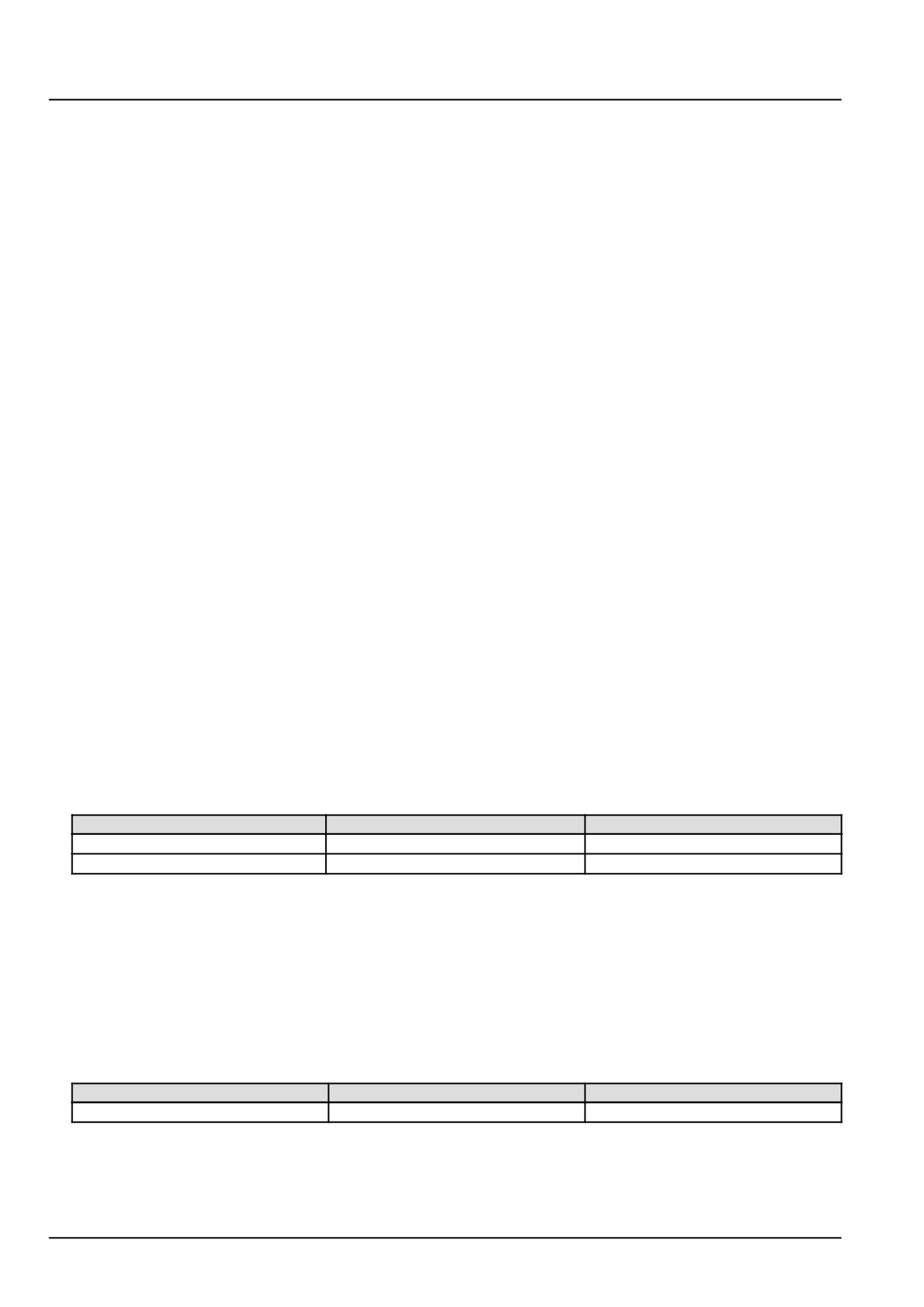
With the key in the OFF position, use a multimeter to perform the following continuity check on the engine harness
(EN) side :
From
To
Value
X-9003 pin 2
X-9003 pin 1
There should be no continuity.
X-9003 pin 2
Chassis ground
There should be no continuity.
A. If there is continuity, there is a short to ground condition in the intake manifold temperature sensor B-9001 in
the engine harness (EN) wiring. Locate and repair the shorted conductor.
B. If there no continuity, leave connector X-9003 disconnected and continue to Step 3.
3.
Check the intake manifold temperature sensor B-9001 engine harness (EN) wiring.
Disconnect the vehicle harness (VE) from the ECU A-9000 at connector X-9001.
With the key in the OFF position, use a multimeter to perform the following continuity check on the engine harness
(EN) side :
From
To
Value
X-9001 pin A55
All pins in connector X-9001
There should be no continuity.
A. If there is continuity, there is a short circuit in the intake manifold temperature sensor B-9001 in the engine har-
ness (EN) wiring. Use the appropriate service manual, if necessary, to locate and repair the shorted conductor.
B. If there no continuity, leave connector X-9003 disconnected and continue to Step 4.
18
Electrical systems - FAULT CODES
4. Replace the intake manifold temperature sensor B-9001.
Use the Electronic Service Tool (EST) to check the status of this fault.
A. If the fault is no longer active, return the machine to service.
B. If the fault is still active, check the ECU A-9000 for the appropriate software and re-flash, if necessary.
5. Visually inspect the relevant harnesses and connectors for damage, bent or dislocated pins, corroded terminals,
or broken wires. Verify that the connectors are fully installed. Flex the harnesses involved to reveal intermittent
breaks or shorts in the wiring concerned. Operate the machine while you monitor the display.
A. If you find damage or the display indicates other than normal display readings, then repair the damage discov-
ered during the inspection or locate and repair the other than normal display condition and verify that the error
has been resolved.
B. If you do not find damage and the display indicates only normal readings, then erase the fault code and continue
operation.
Wiring harnesses - Electrical schematic sheet 03 - Engine sensors and fuel injection (engine schematics)
(55.100.DP-C.20.E.03)
19
Electrical systems - FAULT CODES
DTC 134-00-Intake manifold pressure sensor drifted high
Control Module : ECU
Context:
The Engine Control Unit (ECU) A-9000 monitors boost pressure using the intake manifold pressure sensor B-9001.
Boost pressure is compared to environmental pressure by the ECU A-9000. If the ECU A-9000 determines that the
difference between measured boost pressure and environmental pressure is greater than 0.1 bar (1.5 psi), this fault
will occur.
Cause:
The ECU A-9000 has determined that boost pressure is greater than environmental pressure by 0.1 bar (1.5 psi).
Possible failure modes:
1. Faulty intake manifold pressure sensor B-9001, internal failure.
2. Faulty ECU A-9000, software.
Solution:
1.
Verify fault is present and active.
Use the Electronic Service Tool (EST) to check the status of this fault.
A. If the fault is present and active, continue with Step 2.
B. If the fault is no longer present or in an inactive state, the fault may be intermittent and not currently active.
Continue with Step 4.
2.
Use the Electronic Service Tool (EST) to check the status of following related faults:
DTC 134-03 - Intake manifold pressure sensor voltage is higher than expected
DTC 134-04 - Intake manifold pressure sensor voltage is lower than expected
A. If any of the listed faults are active, diagnose them first and then return to this fault.
B. If none of the listed faults are active, continue to Step 3.
3.
Replace the intake manifold pressure sensor B-9001.
Use the EST to verify the status of this fault, .
A. If the fault is no longer active, return the machine to service.
B. If the fault is still active, check the ECU A-9000 for the appropriate software and re-flash, if necessary.
4.
Visually inspect the relevant harnesses and connectors for damage, bent or dislocated pins, corroded terminals,
or broken wires. Verify that the connectors are fully installed. Flex the harnesses involved to reveal intermittent
breaks or shorts in the wiring concerned. Operate the machine while you monitor the display.
A. If you find damage or the display indicates other than normal display readings, then repair the damage discov-
ered during the inspection or locate and repair the other than normal display condition and verify that the error
has been resolved.
B. If you do not find damage and the display indicates only normal readings, then erase the fault code and continue
operation.
20
Electrical systems - FAULT CODES
DTC 134-01-Intake manifold pressure sensor drifted low
Control Module : ECU
Context:
The Engine Control Unit (ECU) A-9000 monitors boost pressure. Boost pressure is compared to environmental pres-
sure by the ECU A-9000. If the ECU A-9000 determines that the boost pressure is less than environmental pressure
by 0.1 bar (1.5 psi), this fault will occur.
Cause:
The ECU A-9000 has determined that boost pressure is less than environmental pressure by 0.1 bar (1.5 psi).
Possible failure modes:
1. Faulty intake manifold pressure sensor B-9001, internal failure.
2. Faulty ECU A-9000, software.
Solution:
1.
Verify fault is present and active.
Use the Electronic Service Tool (EST) to check the status of this fault.
A. If the fault is present and active, continue with Step 2.
B. If the fault is no longer present or in an inactive state, the fault may be intermittent and not currently active.
Continue with Step 4.
2.
Use the Electronic Service Tool (EST) to check the status of following related faults:
DTC 134-03 - Intake manifold pressure sensor voltage is higher than expected
DTC 134-04 - Intake manifold pressure sensor voltage is lower than expected
A. If any of the listed faults are active, diagnose them first and then return to this fault.
B. If none of the listed faults are active, continue to Step 3.
3.
Replace the intake manifold pressure sensor B-9001.
Use the EST to verify the status of this fault, .
A. If the fault is no longer active, return the machine to service.
B. If the fault is still active, check the ECU A-9000 for the appropriate software and re-flash, if necessary.
4.
Visually inspect the relevant harnesses and connectors for damage, bent or dislocated pins, corroded terminals,
or broken wires. Verify that the connectors are fully installed. Flex the harnesses involved to reveal intermittent
breaks or shorts in the wiring concerned. Operate the machine while you monitor the display.
A. If you find damage or the display indicates other than normal display readings, then repair the damage discov-
ered during the inspection or locate and repair the other than normal display condition and verify that the error
has been resolved.
B. If you do not find damage and the display indicates only normal readings, then erase the fault code and continue
operation.
21
Electrical systems - FAULT CODES
DTC 134-03-Intake manifold pressure sensor voltage is higher
than expected
Control Module : ECU
Context:
The Engine Control Unit (ECU) A-9000 monitors the intake manifold pressure sensor B-9001. If the ECU A-9000
determines that the intake manifold pressure sensor B-9001 signal circuit voltage is greater than 4.92 V, this fault will
occur. If this fault is active, the intake manifold pressure value will be frozen at the last valid value for a preliminary
failure or jump to a fixed replacement value of 0.98 bar (14.21 psi) if the failure is validated.
Cause:
The ECU A-9000 has determined that the intake manifold pressure sensor B-9001 signal circuit voltage is greater
than 4.92 V.
Possible failure modes:
1. Faulty intake manifold pressure sensor B-9001 wiring, short to a voltage source.
2. Faulty intake manifold pressure sensor B-9001 wiring, open circuit.
3. Faulty intake manifold pressure sensor B-9001, internal failure.
4. Faulty ECU A-9000, software.
Solution:
1.
Verify fault is present and active.
Use the Electronic Service Tool (EST) to check the status of this fault.
A. If the fault is present and active, continue with Step 2.
B. If the fault is no longer present or in an inactive state, the fault may be intermittent and not currently active.
Continue with Step 6.
2.
Check the intake manifold pressure sensor B-9001 wiring for a short to a voltage source.
Disconnect the engine harness (EN) from the intake manifold pressure sensor B-9001 at connector X-9003.
With the key in the OFF position, use a multimeter to perform the following voltage check on the engine harness
(EN) side :
From
To
Value
X-9003 pin 4
Chassis ground
There should be no voltage.
With the key in the ON position, use a multimeter to perform the following voltage check on the engine harness
side :
From
To
Value
X-9003 pin 4
Chassis ground
There should be less than 5.5 V
A. If there is voltage, there is a short to battery or switched battery in the intake manifold pressure sensor B-9001
wiring. Use the appropriate service manual, if necessary, to locate and repair the shorted conductor.
B. If there is no voltage, leave connector X-9003 disconnected and continue to Step 3.
3.
Check the intake manifold pressure sensor B-9001 wiring in the engine harness (EN) for an open circuit.
Disconnect the engine harness (EN) from the ECU A-9000 at connector X-9001.
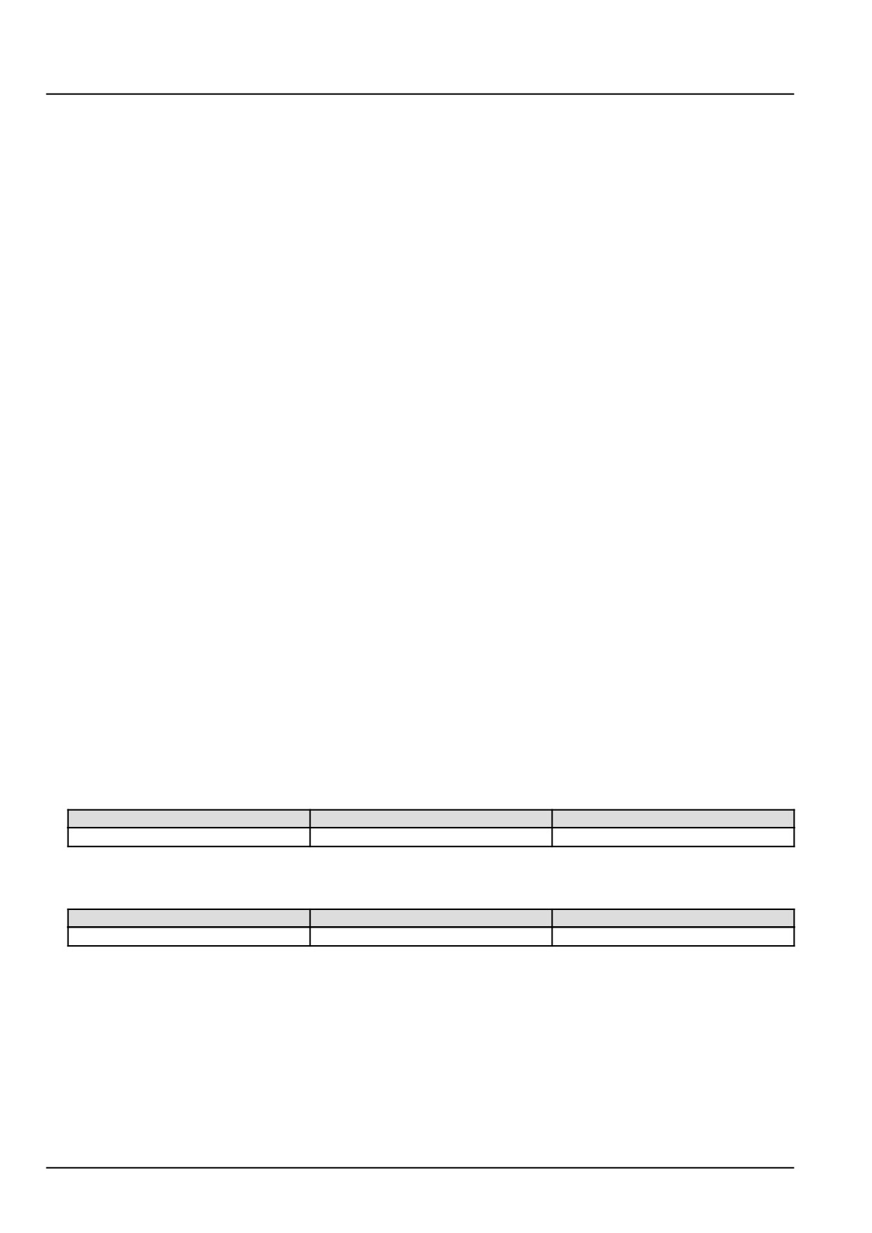
With the key in the OFF position, use a multimeter to perform the following continuity check on the engine harness
(EN) side :
22
Electrical systems - FAULT CODES
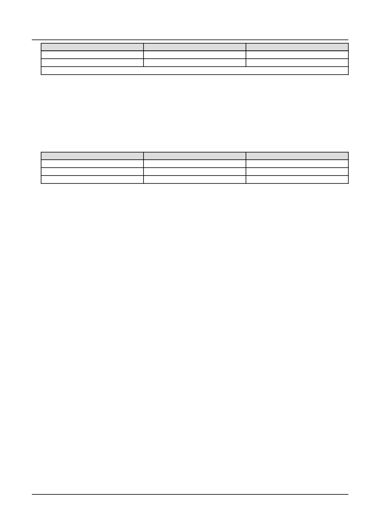
From
To
Value
X-9003 pin 4
X-9001 pin A40
There should be continuity.
X-9003 pin 3
X-9001 pin A10
There should be continuity.
NOTE: Wiggle the harness during the check to promote an intermittent electrical connection.
A. If there is no continuity, there is an open circuit in the intake manifold pressure sensor B-9001 wiring in the
engine harness (EN). Locate and repair the broken conductor.
B. If there is continuity, leave connectors X-9003 and X-9001 disconnected and continue to Step 4.
4.
Check the intake manifold pressure sensor B-9001 wiring in the engine harness (EN) for a short to a voltage
source.
With the key in the OFF position, use a multimeter to perform the following continuity check on the engine harness
(EN) side :
From
To
Value
X-9003 pin 4
X-9003 pin 3
There should be no continuity.
X-9001 pin A40
All pins in connector X-9001
There should be no continuity.
X-9001 pin A10
All pins in connector X-9001
There should be no continuity.
A. If there is continuity, there is a short circuit in the intake manifold pressure sensor B-9001 wiring in the engine
harness (EN). Locate and repair the shorted conductor.
B. If there is no continuity, leave connector X-9003 disconnected and continue to Step 5.
5.
Replace the intake manifold pressure sensor B-9001.
Use the Electronic Service Tool (EST) to check the status of this fault.
A. If the fault is no longer active, return the machine to service.
B. If the fault is still active, check the ECU A-9000 for the appropriate software and re-flash, if necessary.
6.
Visually inspect the relevant harnesses and connectors for damage, bent or dislocated pins, corroded terminals,
or broken wires. Verify that the connectors are fully installed. Flex the harnesses involved to reveal intermittent
breaks or shorts in the wiring concerned. Operate the machine while you monitor the display.
A. If you find damage or the display indicates other than normal display readings, then repair the damage discov-
ered during the inspection or locate and repair the other than normal display condition and verify that the error
has been resolved.
B. If you do not find damage and the display indicates only normal readings, then erase the fault code and continue
operation.
Wiring harnesses - Electrical schematic sheet 03 - Engine sensors and fuel injection (engine schematics)
(55.100.DP-C.20.E.03)
23

Electrical systems - FAULT CODES
DTC 134-04-Intake manifold pressure sensor voltage is lower than
expected
Control Module : ECU
Context:
The Engine Control Unit (ECU) A-9000 monitors the intake manifold pressure sensor B-9001. If the ECU A-9000
determines that the intake manifold pressure sensor B-9001 signal circuit voltage is less than 202.80 mV, this fault
will occur. If this fault is active, the intake manifold pressure value will be frozen at the last valid value for a preliminary
failure or jump to a fixed replacement value of 0.98 bar (14.21 psi) if the failure is validated.
Cause:
The ECU A-9000 has determined that the intake manifold pressure sensor B-9001 signal circuit voltage is less than
202.80 mV.
Possible failure modes:
1. Faulty intake manifold pressure sensor B-9001 wiring, short to ground condition.
2. Faulty intake manifold pressure sensor B-9001, internal failure.
3. Faulty ECU A-9000, software.
Solution:
1.
Verify fault is present and active.
Use the Electronic Service Tool (EST) to check the status of this fault.
A. If the fault is present and active, continue with Step 2.
B. If the fault is no longer present or in an inactive state, the fault may be intermittent and not currently active.
Continue with Step 4.
2.
Check the intake manifold pressure sensor B-9001 wiring in the engine harness (EN) for a short to ground condi-
tion.
Disconnect the engine harness (EN) from the intake manifold pressure sensor B-9001 at connector X-9003.
Disconnect the engine harness (EN) from the ECU A-9000 at connector X-9001.
With the key in the OFF position, use a multimeter to perform the following continuity check on the engine harness
(EN) side :
From
To
Value
X-9003 pin 4
Chassis ground
There should be no continuity.
X-9003 pin 4
X-9003 pin 1
There should be no continuity.
X-9001 pin A40
All pins in connector X-9001
There should be no continuity.
A. If there is continuity, there is a short circuit in the intake manifold pressure sensor B-9001 wiring in the engine
harness (EN). Locate and repair the shorted conductor.
B. If there is no continuity, leave connector X-9003 disconnected and continue to Step 3.
3.
Replace the intake manifold pressure sensor B-9001.
Use the Electronic Service Tool (EST) to check the status of this fault.
A. If the fault is no longer active, return the machine to service.
B. If the fault is still active, check the ECU A-9000 for the appropriate software and re-flash, if necessary.
24
Electrical systems - FAULT CODES
4. Visually inspect the relevant harnesses and connectors for damage, bent or dislocated pins, corroded terminals,
or broken wires. Verify that the connectors are fully installed. Flex the harnesses involved to reveal intermittent
breaks or shorts in the wiring concerned. Operate the machine while you monitor the display.
A. If you find damage or the display indicates other than normal display readings, then repair the damage discov-
ered during the inspection or locate and repair the other than normal display condition and verify that the error
has been resolved.
B. If you do not find damage and the display indicates only normal readings, then erase the fault code and continue
operation.
Wiring harnesses - Electrical schematic sheet 03 - Engine sensors and fuel injection (engine schematics)
(55.100.DP-C.20.E.03)
25
Electrical systems - FAULT CODES
DTC 135-03-Fuel temperature sensor voltage is higher than
expected
Control Module : ECU
Context:
The Engine Control Unit (ECU) A-9000 monitors the fuel temperature sensor B-9002 signal circuit voltage. If the ECU
A-9000 detects a voltage greater than 4.93 V in the signal circuit, this fault will occur. If this fault is not inhibited by
another fault, the ECU A-9000 will freeze the fuel temperature value to 39.96 °C (103.93 °F).
Cause:
The fuel temperature sensor B-9002 signal circuit voltage is greater than 4.93 V.
Possible failure modes:
1. Faulty fuel temperature sensor B-9002 wiring, short to a voltage source.
2. Faulty fuel temperature sensor B-9002 wiring, open circuit.
3. Faulty fuel temperature sensor B-9002, internal failure.
4. Faulty ECU A-9000, software.
Solution:
1.
Verify fault is present and active.
Use the Electronic Service Tool (EST) to check the status of this fault.
A. If the fault is present and active, continue with Step 2.
B. If the fault is no longer present or in an inactive state, the fault may be intermittent and not currently active.
Continue with Step 6.
2.
Check the fuel temperature sensor B-9002 for an internal failure.
Disconnect the engine harness (EN) from the fuel temperature sensor B-9002 at connector X-9005.
Use a multimeter to measure the resistance of the fuel temperature sensor B-9002 on the sensor pins :
From
To
Value
X-9005 pin 1
X-9005 pin 2
At approximately 20.0 °C (68.0 °F),
there should be between 2351 -
2648 Ω.
NOTE: The fuel temperature sensor B-9002 is a Negative Temperature Coefficient (NTC) thermistor. The thermis-
tor’s conductivity increases with increasing temperature and resistance decreases with increasing temperature.
A. If there is a nominal resistance value, e.g. greater than 100 Ω, leave connector X-9005 disconnected and
continue to Step 3.
B. If there is not a nominal resistance value, e.g. 0 Ω, the fuel temperature sensor B-9002 has failed. Replace
the fuel temperature sensor B-9002.
3.
Check the fuel temperature sensor B-9002 wiring for a short to battery.
With the key in the OFF position, use the a multimeter to perform the following voltage check on the engine harness
(EN) side :
From
To
Value
X-9005 pin 1
Chassis ground
There should be no voltage.
With the key in the ON position, use the a multimeter to perform the following voltage check on the engine harness
(EN) side :
26
Electrical systems - FAULT CODES
From
To
Value
X-9005 pin 1
Chassis ground
There should be less than 5.5 V.
A. If the specified values are measured, leave connector X-9005 disconnected and continue to Step 4.
B. If the specified values are not measured, there is a short to battery or switched battery in the fuel temperature
sensor B-9002 wiring. Use the appropriate service manual, if necessary, to locate and repair the failed con-
ductor.
4.
Check the fuel temperature sensor B-9002 engine harness (EN) wiring for an open circuit condition.
Disconnect the engine harness (EN) from the ECU A-9000 at connector X-9001.
With the key in the OFF position, use the a multimeter to perform the following continuity check on the engine
harness (EN) side :
From
To
Value
X-9005 pin 1
X-9001 pin A38
There should be continuity.
X-9005 pin 2
X-9001 pin A23
There should be continuity.
A. If there is continuity, leave connectors X-9005 and X-9001 disconnected and continue to Step 5.
B. If there is no continuity, there is an open circuit in the fuel temperature sensor B-9002 wiring in the engine
harness (EN). Locate and repair the broken conductor.
5.
Check the fuel temperature sensor B-9002 engine harness (EN) wiring for a short circuit condition.
With the key in the OFF position, use the a multimeter to perform the following continuity check on the engine
harness (EN) side :
From
To
Value
X-9001 pin A38
All pins in connector X-9001
There should be no continuity.
A. If there is continuity, there is a short circuit in the fuel temperature sensor B-9002 wiring in the engine harness
(EN). Locate and repair the shorted conductor.
B. If there is no continuity, check the ECU A-9000 for the appropriate software and re-flash, if necessary.
6.
Visually inspect the relevant harnesses and connectors for damage, bent or dislocated pins, corroded terminals,
or broken wires. Verify that the connectors are fully installed. Flex the harnesses involved to reveal intermittent
breaks or shorts in the wiring concerned. Operate the machine while you monitor the display.
A. If you find damage or the display indicates other than normal display readings, then repair the damage discov-
ered during the inspection or locate and repair the other than normal display condition and verify that the error
has been resolved.
B. If you do not find damage and the display indicates only normal readings, then erase the fault code and continue
operation.
Wiring harnesses - Electrical schematic sheet 03 - Engine sensors and fuel injection (engine schematics)
(55.100.DP-C.20.E.03)
27
Electrical systems - FAULT CODES
DTC 135-04-Fuel temperature sensor voltage is lower than expected
Control Module : ECU
Context:
The Engine Control Unit (ECU) A-9000 monitors the fuel temperature sensor B-9002 signal circuit voltage. If the ECU
A-9000 detects a voltage less than 198.00 mV in the signal circuit, this fault will occur. If this fault is not inhibited by
another fault, the ECU A-9000 will freeze the fuel temperature value to 39.96 °C (103.93 °F).
Cause:
The fuel temperature sensor B-9002 signal circuit voltage is less than 198.00 mV.
Possible failure modes:
1. Faulty fuel temperature sensor B-9002 wiring, short to ground condition.
2. Faulty fuel temperature sensor B-9002, internal failure.
3. Faulty ECU A-9000, software.
Solution:
1.
Verify fault is present and active.
Use the Electronic Service Tool (EST) to check the status of this fault.
A. If the fault is present and active, continue with Step 2.
B. If the fault is no longer present or in an inactive state, the fault may be intermittent and not currently active.
Continue with Step 5.
2.
Check the fuel temperature sensor B-9002 for an internal failure.
Disconnect the engine harness (EN) from the fuel temperature sensor B-9002 at connector X-9005.
Use a multimeter to measure the resistance of the fuel temperature sensor B-9002 on the sensor pins :
From
To
Value
X-9005 pin 1
X-9005 pin 2
At approximately 20.0 °C (68.0 °F),
there should be between 2351 -
2648 Ω.
NOTE: The fuel temperature sensor B-9002 is a Negative Temperature Coefficient (NTC) thermistor. The thermis-
tor’s conductivity increases with increasing temperature and resistance decreases with increasing temperature.
A. If there is a nominal resistance value, e.g. greater than 100 Ω, leave connector X-9005 disconnected and
continue to Step 3.
B. If there is not a nominal resistance value, e.g. 0 Ω, the fuel temperature sensor B-9002 has failed. Replace
the fuel temperature sensor B-9002.
3.
Check the fuel temperature sensor B-9002 engine harness (EN) wiring for a short to ground condition.
With the key in the OFF position, use the a multimeter to perform the following continuity checks for a short to
ground condition on the engine harness (EN) side :
From
To
Value
X-9005 pin 1
X-9005 pin 2
There should be no continuity.
X-9005 pin 1
Chassis ground
There should be no continuity.
A. If there is no continuity, leave connector X-9005 disconnected and continue to Step 4.
B. If there is continuity, there is a short to ground in the fuel temperature sensor B-9002 wiring in the engine
harness (EN). Locate and repair the failed conductor.
28
Electrical systems - FAULT CODES
4. Check the fuel temperature sensor B-9002 engine harness (EN) wiring for a short to ground condition.
Disconnect the engine harness (EN) from the ECU A-9000 at connector X-9001.
With the key in the OFF position use the a multimeter to perform the following continuity checks for a short to
ground condition on the engine harness (EN) side :
From
To
Value
X-9005 pin 1
All pins in connector X-9001.
There should be no continuity.
A. If the specified values are not measured, there is a fault in the fuel temperature sensor B-9002 engine harness
(EN) wiring. Locate and repair the failed conductor.
B. If there is no continuity, check the ECU A-9000 for the appropriate software and re-flash, if necessary.
5. Visually inspect the relevant harnesses and connectors for damage, bent or dislocated pins, corroded terminals,
or broken wires. Verify that the connectors are fully installed. Flex the harnesses involved to reveal intermittent
breaks or shorts in the wiring concerned. Operate the machine while you monitor the display.
A. If you find damage or the display indicates other than normal display readings, then repair the damage discov-
ered during the inspection or locate and repair the other than normal display condition and verify that the error
has been resolved.
B. If you do not find damage and the display indicates only normal readings, then erase the fault code and continue
operation.
Wiring harnesses - Electrical schematic sheet 03 - Engine sensors and fuel injection (engine schematics)
(55.100.DP-C.20.E.03)
29
Electrical systems - FAULT CODES
DTC 136-03-Fuel rail pressure sensor voltage is higher than
expected
Control Module : ECU
NOTE: If the rail pressure sensor B-9004 is replaced, it is necessary to perform the Replacement of the Rail Pressure
sensor - Reset ECU Data with the Electronic Service Tool (EST) before you return the machine to service. See
Common rail pressure sensor - Configure - Reset ECU data (Rail pressure sensor) (55.010), if necessary.
Context:
The Engine Control Unit (ECU) A-9000 monitors the rail pressure sensor B-9004. If the ECU A-9000 detects a voltage
greater than 4.90 V in the rail pressure sensor B-9004 signal circuit, this fault will occur.
Cause:
The ECU A-9000 has detected a voltage greater than 4.90 V in the rail pressure sensor B-9004 signal circuit.
Possible failure modes:
1. Faulty rail pressure sensor B-9004 wiring, short to a voltage source.
2. Faulty rail pressure sensor B-9004 wiring, open circuit.
3. Faulty rail pressure sensor B-9004, internal failure.
4. Faulty ECU A-9000, software.
Solution:
1.
Verify fault is present and active.
Use the Electronic Service Tool (EST) to check the status of this fault.
A. If the fault is present and active, continue with Step 2.
B. If the fault is no longer present or in an inactive state, the fault may be intermittent and not currently active.
Continue with Step 6.
2.
Check the rail pressure sensor B-9004 wiring for a short circuit condition.
Disconnect the engine harness (EN) from the rail pressure sensor B-9004 at connector X-9026.
With the key in the OFF position, use a multimeter to perform the following voltage check on the engine harness
(EN) side :
From
To
Value
X-9026 pin 2
Chassis ground
There should be no voltage.
With the key in the ON position, use a multimeter to perform the following voltage check on the engine harness
(EN) side :
From
To
Value
X-9026 pin 2
Chassis ground
There should be less than 5.5 V
A. If the specified values are not measured, there is a short to battery or switched battery in the rail pressure
sensor B-9004 wiring in the engine harness (EN). Locate and repair the broken conductor.
B. If the specified values are measured, leave connector X-9026 disconnected and continue to Step 3.
3.
Check the rail pressure sensor B-9004 engine harness (VE) wiring for an open circuit.
Disconnect the engine harness (EN) from the ECU A-9000 at connector X-9001.
With the key in the OFF position, use a multimeter to perform the following continuity check on the engine harness
(EN) side :
30
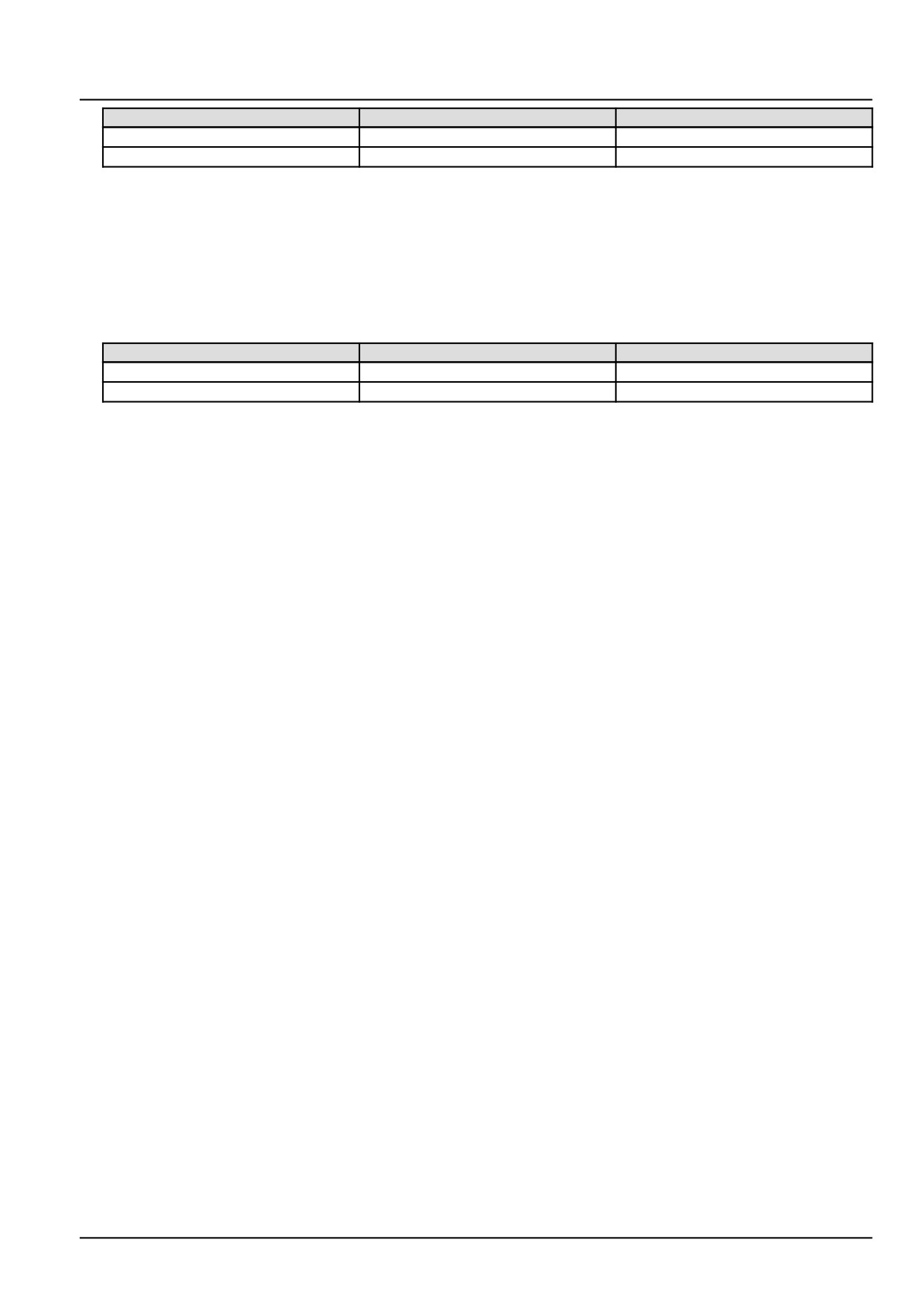
Electrical systems - FAULT CODES
From
To
Value
X-9026 pin 2
X-9001 pin A41
There should be continuity.
X-9026 pin 3
X-9001 pin A11
There should be continuity.
A. If there is no continuity, there is an open circuit in the rail pressure sensor B-9004 engine harness (EN) wiring.
Locate and repair the broken conductor.
B. If there is continuity, leave connectors X-9026 and X-9001 disconnected and continue to Step 4.
4.
Check the rail pressure sensor B-9004 engine harness (EN) wiring for a short to a voltage source.
With the key in the OFF position, use a multimeter to perform the following continuity check on the engine harness
(EN) side :
From
To
Value
X-9026 pin 2
X-9026 pin 3
There should be no continuity.
X-9001 pin A41
All pins in connector X-9001
There should be no continuity.
A. If there is continuity, there is a short circuit in the rail pressure sensor B-9004 engine harness (EN) wiring.
Locate and repair the shorted conductor.
B. If there is no continuity, leave connector X-9026 disconnected and continue to Step 5.
5.
Replace the rail pressure sensor B-9004.
Use the Electronic Service Tool (EST) to check the status of this fault.
A. If the fault is no longer active, return the machine to service.
B. If the fault is still active, check the ECU A-9000 for the appropriate software and re-flash, if necessary.
6.
Visually inspect the relevant harnesses and connectors for damage, bent or dislocated pins, corroded terminals,
or broken wires. Verify that the connectors are fully installed. Flex the harnesses involved to reveal intermittent
breaks or shorts in the wiring concerned. Operate the machine while you monitor the display.
A. If you find damage or the display indicates other than normal display readings, then repair the damage discov-
ered during the inspection or locate and repair the other than normal display condition and verify that the error
has been resolved.
B. If you do not find damage and the display indicates only normal readings, then erase the fault code and continue
operation.
Wiring harnesses - Electrical schematic sheet 03 - Engine sensors and fuel injection (engine schematics)
(55.100.DP-C.20.E.03)
31
Electrical systems - FAULT CODES
DTC 136-04-Fuel rail pressure sensor voltage is lower than expected
Control Module : ECU
NOTE: If the rail pressure sensor B-9004 is replaced, it is necessary to perform the Replacement of the Rail Pressure
sensor - Reset ECU Data with the Electronic Service Tool (EST) before you return the machine to service. See
Common rail pressure sensor - Configure - Reset ECU data (Rail pressure sensor) (55.010), if necessary.
Context:
The Engine Control Unit (ECU) A-9000 monitors the rail pressure sensor B-9004. If the ECU A-9000 detects a voltage
less than 342.20 mV in the rail pressure sensor B-9004 signal circuit, this fault will occur.
Cause:
The ECU A-9000 has detected a voltage less than 342.20 mV in the rail pressure sensor B-9004 signal circuit.
Possible failure modes:
1. Faulty rail pressure sensor B-9004 wiring, short to ground condition.
2. Faulty rail pressure sensor B-9004, internal failure.
3. Faulty ECU A-9000, software.
Solution:
1.
Verify fault is present and active.
Use the Electronic Service Tool (EST) to check the status of this fault.
A. If the fault is present and active, continue with Step 2.
B. If the fault is no longer present or in an inactive state, the fault may be intermittent and not currently active.
Continue with Step 5.
2.
Check the rail pressure sensor B-9004 engine harness (EN) wiring for a short circuit condition.
Disconnect the engine harness (EN) from the rail pressure sensor B-9004 at connector X-9026.
Disconnect the engine harness (EN) from the ECU A-9000 at connector X-9001.
With the key in the OFF position, use a multimeter to perform the following continuity check on the engine harness
(EN) side :
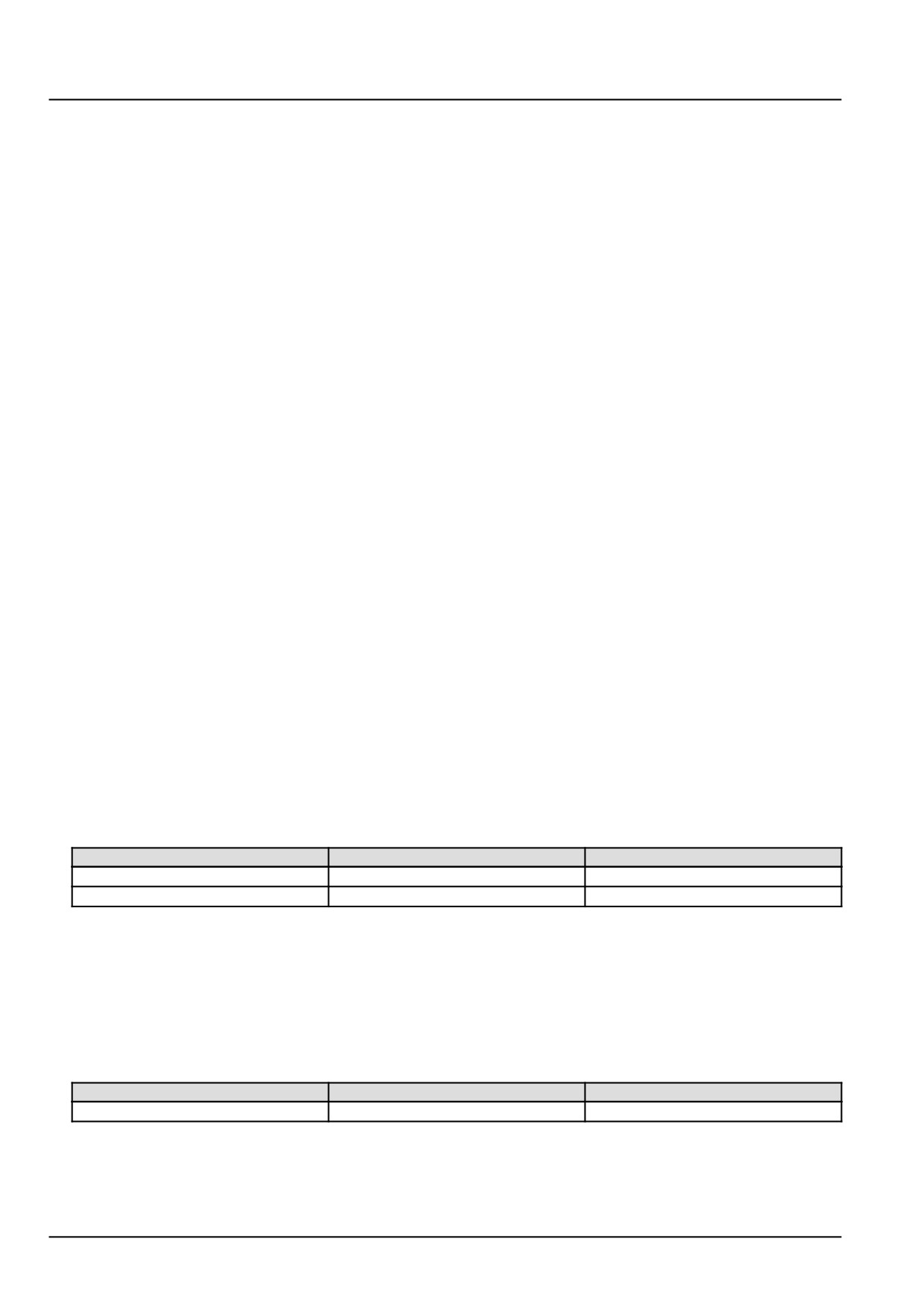
From
To
Value
X-9026 pin 2
X-9026 pin 1
There should be no continuity.
X-9026 pin 2
Chassis ground
There should be no continuity.
A. If there is continuity, there is a short to ground in the rail pressure sensor B-9004 engine harness (EN) wiring.
Locate and repair the shorted conductor.
B. If there is no continuity, leave connectors X-9026 and X-9001 disconnected and continue to Step 3.
3.
Check the rail pressure sensor B-9004 vehicle harness (VE) wiring for a short to ground condition.
With the key in the OFF position, use a multimeter to perform the following continuity check on the engine harness
(EN) side :
From
To
Value
X-9001 pin A41
All pins in connector X-9001
There should be no continuity.
A. If there is continuity, there is a short circuit in the rail pressure sensor B-9004 engine harness (EN) wiring.
Locate and repair the broken conductor.
B. If there is no continuity, leave connector X-9026 and continue to Step 4.
32
Electrical systems - FAULT CODES
4. Replace the rail pressure sensor B-9004.
Use the Electronic Service Tool (EST) to check the status of this fault.
A. If the fault is no longer active, return the machine to service.
B. If the fault is still active, check the ECU A-9000 for the appropriate software and re-flash, if necessary.
5. Visually inspect the relevant harnesses and connectors for damage, bent or dislocated pins, corroded terminals,
or broken wires. Verify that the connectors are fully installed. Flex the harnesses involved to reveal intermittent
breaks or shorts in the wiring concerned. Operate the machine while you monitor the display.
A. If you find damage or the display indicates other than normal display readings, then repair the damage discov-
ered during the inspection or locate and repair the other than normal display condition and verify that the error
has been resolved.
B. If you do not find damage and the display indicates only normal readings, then erase the fault code and continue
operation.
Wiring harnesses - Electrical schematic sheet 05 - Engine Control Unit (ECU) engine connector
(55.100.DP-C.20.E.05)
Wiring harnesses - Electrical schematic sheet 06 - Engine control and fuel injection (55.100.DP-C.20.E.06)
33
Electrical systems - FAULT CODES
DTC 137-02-Fuel pressure relief valve reached maximum allowed
opening count
Control Module : ECU
NOTE: If the Pressure Relief Valve (PRV) is replaced, it is necessary to perform the Replacement of the Rail Pressure
Relief Valve (PRV) - Reset ECU Data with the Electronic Service Tool (EST) before you return the machine to service.
See Common rail Relief valve - Configure - Reset ECU data (10.218), if necessary.
NOTE: If the rail pressure sensor B-9004 is replaced, it is necessary to perform the Replacement of the Rail Pressure
sensor - Reset ECU Data with the Electronic Service Tool (EST) before you return the machine to service. See
Common rail pressure sensor - Configure - Reset ECU data (Rail pressure sensor) (55.010), if necessary.
Context:
The Engine Control Unit (ECU) A-9000 monitors the fuel Pressure Relief Valve (PRV). If the ECU A-9000 determines
that the PRV has exceeded its maximum open count, 50 times, this fault will occur. If the PRV has opened more than
50 times, the PRV must be replaced. Other active faults may have caused this fault to occur. For more information
regarding fuel system troubleshooting, see Fuel injection system - Troubleshooting (10.218).
Cause:
The ECU A-9000 has determined that the PRV has opened more than 50 times.
Possible failure modes:
1. Faulty fuel metering unit Y-9000, stuck open.
2. Faulty rail pressure sensor B-9004, drifted signal.
3. Faulty PRV, opening pressure too low.
4. Faulty fuel back-flow, clogged or damaged.
5. Faulty ECU A-9000, software.
34
Electrical systems - FAULT CODES
DTC 137-03-Fuel pressure relief valve is open
Control Module : ECU
NOTE: If the Pressure Relief Valve (PRV) is replaced, it is necessary to perform the Replacement of the Rail Pressure
Relief Valve (PRV) - Reset ECU Data with the Electronic Service Tool (EST) before you return the machine to service.
See Common rail Relief valve - Configure - Reset ECU data (10.218), if necessary.
NOTE: If the rail pressure sensor B-9004 is replaced, it is necessary to perform the Replacement of the Rail Pressure
sensor - Reset ECU Data with the Electronic Service Tool (EST) before you return the machine to service. See
Common rail pressure sensor - Configure - Reset ECU data (Rail pressure sensor) (55.010), if necessary.
Context:
The Engine Control Unit (ECU) A-9000 monitors the Pressure Relief Valve (PRV). If the ECU A-9000 commands the
PRV to open by a pressure shock, this fault will occur. Other active faults may have caused this fault to occur. For
more information regarding fuel system troubleshooting, see Fuel injection system - Troubleshooting (10.218).
Cause:
The ECU A-9000 has determined that the PRV is open.
Possible failure modes:
1. Faulty fuel metering unit Y-9000, stuck open.
2. Faulty fuel injectors.
3. Faulty rail pressure sensor B-9004, drifted signal.
4. Faulty PRV, opening pressure too low.
5. Faulty fuel back-flow, clogged or damaged.
6. Faulty ECU A-9000, software.
35
Electrical systems - FAULT CODES
DTC 137-04-Fuel pressure relief valve is forced to open, perform
pressure increase
Control Module : ECU
NOTE: If the Pressure Relief Valve (PRV) is replaced, it is necessary to perform the Replacement of the Rail Pressure
Relief Valve (PRV) - Reset ECU Data with the Electronic Service Tool (EST) before you return the machine to service.
See Common rail Relief valve - Configure - Reset ECU data (10.218), if necessary.
NOTE: If the rail pressure sensor B-9004 is replaced, it is necessary to perform the Replacement of the Rail Pressure
sensor - Reset ECU Data with the Electronic Service Tool (EST) before you return the machine to service. See
Common rail pressure sensor - Configure - Reset ECU data (Rail pressure sensor) (55.010), if necessary.
Context:
The Engine Control Unit (ECU) A-9000, if necessary, will set the engine into limp home mode. This process is achieved
in two steps by the ECU A-9000, a pressure increase and a pressure shock. The ECU A-9000 will execute step one
by a fuel pressure increase. This is achieved by fully opening the fuel metering unit Y-9000, thus allowing maximum
fuel delivery. If this fault is active, the ECU A-9000 has performed step one for achieving limp home mode, a fuel
pressure increase. Other active faults may have caused this fault to occur. For more information regarding fuel sys-
tem troubleshooting, see Fuel injection system - Troubleshooting (10.218).
Cause:
The ECU A-9000 has performed a fuel pressure increase to achieve limp home mode.
36
Electrical systems - FAULT CODES
DTC 137-12-Averaged rail pressure is outside the expected
tolerance range
Control Module : ECU
NOTE: If the Pressure Relief Valve (PRV) is replaced, it is necessary to perform the Replacement of the Rail Pressure
Relief Valve (PRV) - Reset ECU Data with the Electronic Service Tool (EST) before you return the machine to service.
See Common rail Relief valve - Configure - Reset ECU data (10.218), if necessary.
NOTE: If the rail pressure sensor B-9004 is replaced, it is necessary to perform the Replacement of the Rail Pressure
sensor - Reset ECU Data with the Electronic Service Tool (EST) before you return the machine to service. See
Common rail pressure sensor - Configure - Reset ECU data (Rail pressure sensor) (55.010), if necessary.
Context:
The Engine Control Unit (ECU) A-9000 monitors fuel rail pressure using the rail pressure sensor B-9004. After a fuel
pressure evaluation, if the ECU A-9000 suspects that the Pressure Relief Valve (PRV) should be open but has not
opened, this fault occur. If this fault is active, the ECU A-9000 has performed step one for achieving limp home mode,
a fuel pressure increase. Other active faults may have caused this fault to occur. For more information regarding fuel
system troubleshooting, see Fuel injection system - Troubleshooting (10.218).
Cause:
The ECU A-9000 has determined that the PRV should be open but is not open.
Possible failure modes:
1. Faulty PRV, unable to open or partially open.
2. Faulty PRV fuel back-flow, clogged or damaged.
3. Faulty rail pressure sensor B-9004, drifted signal.
4. Faulty ECU A-9000, software.
37
Electrical systems - FAULT CODES
DTC 141-02-Crankshaft speed sensor values are not plausible
Control Module : ECU
Context:
The Engine Control Unit (ECU) A-9000 monitors the crankshaft position sensor B-9007 characteristics for angle,
speed determination, signal plausibility, and quality. If the ECU A-9000 determines that there are no crankshaft posi-
tion signals detected for at least 4 engine revolutions, this fault will occur.
Cause:
The ECU A-9000 has determined that there is no crankshaft position signals detected for at least 4 engine revolutions.
Possible failure modes:
1. Faulty crankshaft position sensor B-9007, not fully seated or loose.
2. Faulty crankshaft tone wheel, damaged or misaligned.
3. Faulty crankshaft position sensor B-9007 wiring, short circuit.
4. Faulty crankshaft position sensor B-9007, internal failure.
5. Faulty ECU A-9000, software.
Solution:
1.
Verify fault is present and active.
Use the Electronic Service Tool (EST) to check the status of this fault.
A. If the fault is present and active, continue with Step 2.
B. If the fault is no longer present or in an inactive state, the fault may be intermittent and not currently active.
Continue with Step 7.
2.
Check the physical integrity of the crankshaft position sensor B-9007. The sensor should be fully seated and
mounted tightly.
Remove the crankshaft position sensor B-9007 and inspect the crankshaft tool wheel. The tone wheel should not
be damaged or loose.
A. If the sensor or tone wheel is damaged or is not mounted/secured properly, repair as necessary.
B. If the sensor or tone wheel is not damaged and is mounted/secured properly, continue to Step 3.
3.
Check the crankshaft position sensor B-9007 wiring for a short circuit to battery condition.
Disconnect the engine harness (EN) from the crankshaft position sensor B-9007 at connector X-9039.
With the key in the OFF position, use a multimeter to perform the following voltage check on the engine harness
(EN) side :
From
To
Value
X-9039 pin 2
Chassis ground
There should be no voltage.
X-9039 pin 1
Chassis ground
There should be no voltage.
A. If there is no voltage, leave connector X-9039 disconnected and continue to Step 4.
B. If there is voltage, there is a short circuit to battery in the crankshaft position sensor B-9007 engine harness
(EN) wiring. Locate and repair the shorted conductor.
4.
Check the crankshaft position sensor B-9007 engine harness (EN) wiring.
With the key in the ON position, use a multimeter to perform the following voltage check on the engine harness
(EN) side :
38
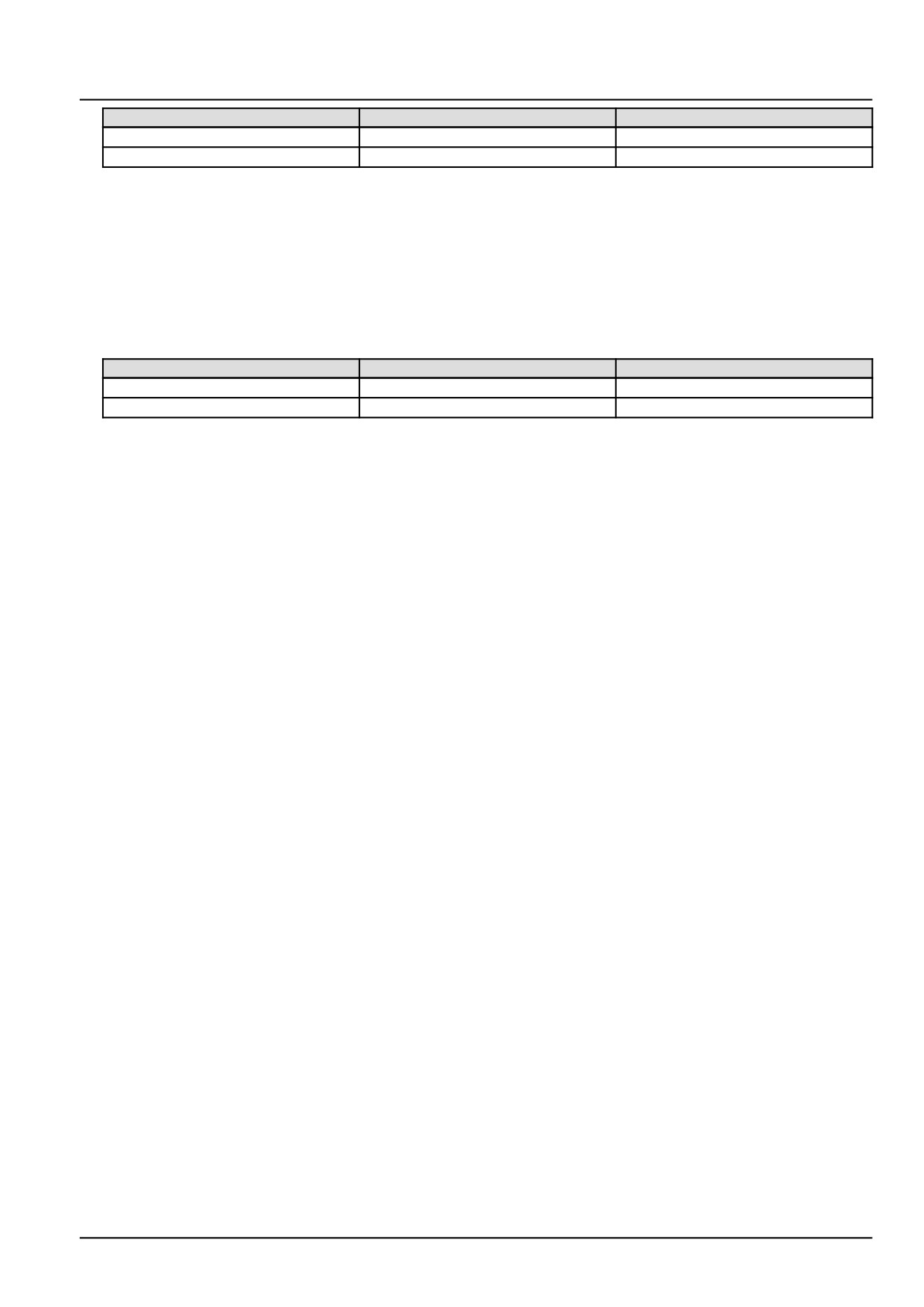
Electrical systems - FAULT CODES
From
To
Value
X-9039 pin 2
Chassis ground
There should be between 2.4 - 2.6 V.
X-9039 pin 1
Chassis ground
There should be between 2.4 - 2.6 V.
A. If there is between 2.4 - 2.6 V, leave connector X-9039 disconnected and continue to Step 6.
B. If there is not between 2.4 - 2.6 V, continue to Step 5.
5.
Check the crankshaft position sensor B-9007 engine harness (EN) wiring for an open circuit.
Disconnect the engine harness (EN) from the ECU A-9000 at connector X-9001.
With the key in the OFF position, use a multimeter to perform the following continuity checks for an open circuit
on the engine harness (EN) side :
From
To
Value
X-9039 pin 2
X-9001 pin A44
There should be continuity.
X-9039 pin 1
X-9001 pin A59
There should be continuity.
A. If there is continuity, leave connectors X-9039 and X-9001 disconnected and continue to Step 5.
B. If there is no continuity, there is an open circuit in the crankshaft position sensor B-9007 circuit wiring in the
engine harness (EN). Locate and repair the broken conductor.
6.
Replace the crankshaft position sensor B-9007.
Use the Electronic Service Tool (EST) to verify the status of this fault.
A. If the fault has been resolved, return the machine to service.
B. If the fault has not been resolved, check the ECU A-9000 for the appropriate software and re-flash, if necessary.
7.
Visually inspect the relevant harnesses and connectors for damage, bent or dislocated pins, corroded terminals,
or broken wires. Verify that the connectors are fully installed. Flex the harnesses involved to reveal intermittent
breaks or shorts in the wiring concerned. Operate the machine while you monitor the display.
A. If you find damage or the display indicates other than normal display readings, then repair the damage discov-
ered during the inspection or locate and repair the other than normal display condition and verify that the error
has been resolved.
B. If you do not find damage and the display indicates only normal readings, then erase the fault code and continue
operation.
Wiring harnesses - Electrical schematic sheet 03 - Engine sensors and fuel injection (engine schematics)
(55.100.DP-C.20.E.03)
39
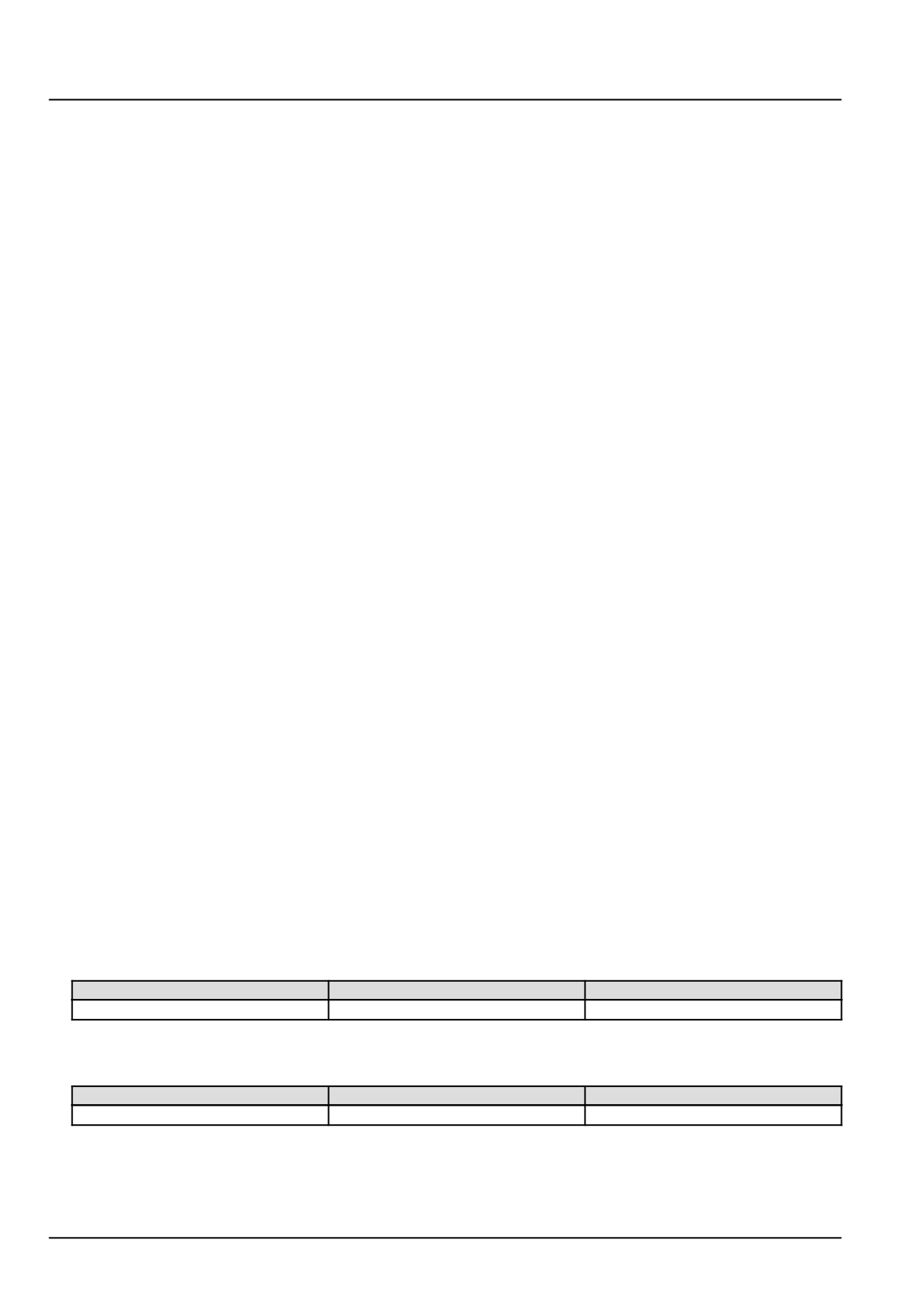
Electrical systems - FAULT CODES
DTC 141-04-Crankshaft speed sensor pattern is not plausible
Control Module : ECU
Context:
The Engine Control Unit (ECU) A-9000 monitors the crankshaft position sensor B-9007 characteristics for angle,
speed determination, signal plausibility, and quality. If the ECU A-9000 detects greater than 80 crankshaft position
signal plausibility errors, this fault will occur.
Cause:
The ECU A-9000 has detected more than 80 crankshaft position signal plausibility errors.
Possible failure modes:
1. Faulty crankshaft position sensor B-9007, not fully seated or loose.
2. Faulty crankshaft tone wheel, damaged or misaligned.
3. Faulty crankshaft position sensor B-9007 wiring, short circuit.
4. Faulty crankshaft position sensor B-9007, internal failure.
5. Faulty ECU A-9000, software.
Solution:
1.
Verify fault is present and active.
Use the Electronic Service Tool (EST) to check the status of this fault.
A. If the fault is present and active, continue with Step 2.
B. If the fault is no longer present or in an inactive state, the fault may be intermittent and not currently active.
Continue with Step 7.
2.
Check the physical integrity of the crankshaft position sensor B-9007. The sensor should be fully seated and
mounted tightly.
Remove the crankshaft position sensor B-9007 and inspect the crankshaft tool wheel. The tone wheel should not
be damaged or loose.
A. If the sensor or tone wheel is damaged or is not mounted/secured properly, repair as necessary.
B. If the sensor or tone wheel is not damaged and is mounted/secured properly, continue to Step 3.
3.
Check the crankshaft position sensor B-9007 wiring for a short to a voltage source.
Disconnect the engine harness (EN) from the crankshaft position sensor B-9007 at connector X-9039.
With the key in the OFF position, use a multimeter to perform the following voltage check on the engine harness
(EN) side :
From
To
Value
X-9039 pin 2
Chassis ground
There should be no voltage.
With the key in the ON position, use a multimeter to perform the following voltage check on the engine harness
(EN) side :
From
To
Value
X-9039 pin 2
Chassis ground
There should be 2.4 - 2.6 V voltage.
A. If there is no voltage, leave connector X-9039 disconnected and continue to Step 4.
B. If there is voltage, there is a short to battery or key switch battery in the crankshaft position sensor B-9007
wiring. Locate and repair the shorted conductor.
40
Electrical systems - FAULT CODES
4.
Check the crankshaft position sensor B-9007 engine harness (EN) wiring for an open circuit.
Disconnect the engine harness (EN) from the ECU A-9000 at connector X-9001.
With the key in the OFF position, use a multimeter to perform the following continuity checks for an open circuit
on the engine harness (EN) side :
From
To
Value
X-9039 pin 2
X-9001 pin A44
There should be continuity.
X-9039 pin 1
X-9001 pin A59
There should be continuity.
X-9039 pin 3
X-9001 pin A58
There should be continuity.
A. If there is continuity, leave connectors X-9039 and X-9001 disconnected and continue to Step 5.
B. If there is no continuity, there is an open circuit in the crankshaft position sensor B-9007 circuit wiring in the
engine harness (EN). Locate and repair the broken conductor.
5.
Check the crankshaft position sensor B-9007 engine harness (EN) wiring for a short circuit.
With the key in the OFF position, use a multimeter to perform the following continuity checks for a short circuit on
the engine harness (EN) side :
From
To
Value
X-9039 pin 2
Chassis ground
There should be no continuity.
X-9039 pin 2
X-9039 pin 1
There should be no continuity.
X-9039 pin 2
X-9039 pin 3
There should be no continuity.
X-9001 pin A44
All pins in connector X-9001
There should be no continuity.
A. If there is no continuity, leave connector X-9039 disconnected and continue to Step 6.
B. If there is no continuity, there is an open circuit in the crankshaft position sensor B-9007 circuit wiring in the
engine harness (EN). Locate and repair the broken conductor.
6.
Replace the crankshaft position sensor B-9007.
Use the Electronic Service Tool (EST) to verify the status of this fault, DTC 141-Sig - Crankshaft sensor failure.
A. If the fault has been resolved, return the machine to service.
B. If the fault has not been resolved, check the ECU A-9000 for the appropriate software and re-flash, if necessary.
7.
Visually inspect the relevant harnesses and connectors for damage, bent or dislocated pins, corroded terminals,
or broken wires. Verify that the connectors are fully installed. Flex the harnesses involved to reveal intermittent
breaks or shorts in the wiring concerned. Operate the machine while you monitor the display.
A. If you find damage or the display indicates other than normal display readings, then repair the damage discov-
ered during the inspection or locate and repair the other than normal display condition and verify that the error
has been resolved.
B. If you do not find damage and the display indicates only normal readings, then erase the fault code and continue
operation.
Wiring harnesses - Electrical schematic sheet 03 - Engine sensors and fuel injection (engine schematics)
(55.100.DP-C.20.E.03)
41
Electrical systems - FAULT CODES
DTC 143-02-Camshaft speed sensor values are not plausible
Control Module : ECU
Context:
The Engine Control Unit (ECU) A-9000 monitors the camshaft position sensor B-9017 characteristics for angle, speed
determination, signal plausibility, and quality. If the ECU A-9000 determines that no camshaft edge is detected for at
least four crankshaft revolutions, this fault will occur.
Cause:
The ECU A-9000 has detected no camshaft edge for at least four crankshaft revolutions.
Possible failure modes:
1. Faulty camshaft position sensor B-9017, wiring.
2. Faulty camshaft position sensor B-9017, improperly seated or mounted.
3. Faulty camshaft position sensor B-9017, internal failure.
4. Faulty ECU A-9000, software.
Solution:
1.
Verify fault is present and active.
Use the Electronic Service Tool (EST) to check the status of this fault.
A. If the fault is present and active, continue with Step 2.
B. If the fault is no longer present or in an inactive state, the fault may be intermittent and not currently active.
Continue with Step 5.
2.
Check the physical integrity of the camshaft speed sensor B-9017. The sensor should be fully seated and mounted
tightly.
A. If the sensor is not mounted/secured properly, repair as necessary.
B. If the sensor is not damaged and is mounted/secured properly, continue to Step 3.
3.
Check the camshaft position sensor B-9017 wiring in the engine harness (EN) for an open circuit.
Disconnect the engine harness (EN) from the camshaft position sensor at connector X-9008.
Disconnect the engine harness (EN) from the ECU A-9000 at connector X-9001.
With the key in the OFF position, use a multimeter to perform the following continuity check on the engine harness
(EN) side :
From
To
Value
X-9008 pin 1
X-9001 pin A28
There should be continuity.
X-9008 pin 2
X-9001 pin A14
There should be continuity.
X-9008 pin 3
X-9001 pin A13
There should be continuity.
X-9008 pin 2
Chassis ground
There should be no continuity.
X-9001 pin A14
All other pins on connector X-9001
There should be no continuity.
With the key in the ON position, use a multimeter to perform the following voltage check on the engine harness
(EN) side :
From
To
Value
X-9001 pin A14
Chassis ground
There should be no voltage.
A. If there is continuity, leave connectors X-9008 and X-9001 disconnected and continue to Step 4.
42
Electrical systems - FAULT CODES
B. If there is no continuity, there is an open circuit in the camshaft position sensor B-9017 wiring. Locate and
repair the broken conductor.
4. Replace the camshaft position sensor B-9017.
Use the Electronic Service Tool (EST) to verify the status of this fault, DTC 143-Min - Camshaft sensor failure.
A. If the fault has been resolved, return the machine to service.
B. If the fault has not been resolved, check the ECU A-9000 for the appropriate software and re-flash, if necessary.
5. Visually inspect the relevant harnesses and connectors for damage, bent or dislocated pins, corroded terminals,
or broken wires. Verify that the connectors are fully installed. Flex the harnesses involved to reveal intermittent
breaks or shorts in the wiring concerned. Operate the machine while you monitor the display.
A. If you find damage or the display indicates other than normal display readings, then repair the damage discov-
ered during the inspection or locate and repair the other than normal display condition and verify that the error
has been resolved.
B. If you do not find damage and the display indicates only normal readings, then erase the fault code and continue
operation.
Wiring harnesses - Electrical schematic sheet 03 - Engine sensors and fuel injection (engine schematics)
(55.100.DP-C.20.E.03)
43
Electrical systems - FAULT CODES
DTC 143-04-Camshaft speed sensor pattern is not plausible
Control Module : ECU
Context:
The Engine Control Unit (ECU) A-9000 monitors the camshaft position sensor B-9017 characteristics for angle, speed
determination, signal plausibility, and quality. If the ECU A-9000 determines that the camshaft signal does not match
the expected pattern (edge, distance, level) or not all expected camshaft edges are detected during an engine revo-
lution, this fault will occur.
Cause:
The ECU A-9000 has detected a camshaft pattern signal error.
Possible failure modes:
1. Faulty camshaft position sensor B-9017 wiring.
2. Faulty camshaft position sensor B-9017, improperly seated or mounted.
3. Faulty camshaft position sensor B-9017, internal failure.
4. Faulty ECU A-9000, software.
Solution:
1.
Verify fault is present and active.
Use the Electronic Service Tool (EST) to check the status of this fault.
A. If the fault is present and active, continue with Step 2.
B. If the fault is no longer present or in an inactive state, the fault may be intermittent and not currently active.
Continue with Step 6.
2.
Check the physical integrity of the camshaft speed sensor B-9017. The sensor should be fully seated and mounted
tightly.
A. If the sensor is not mounted/secured properly, repair as necessary.
B. If the sensor is not damaged and is mounted/secured properly, continue to Step 3.
3.
Check the camshaft position sensor B-9017 wiring in the engine harness (EN) for an open circuit.
Disconnect the engine harness (EN) from the camshaft position sensor at connector X-9008.
Disconnect the engine harness (EN) from the ECU A-9000 at connector X-9001.
With the key in the OFF position, use a multimeter to perform the following continuity check on the engine harness
(EN) side :
From
To
Value
X-9008 pin 2
X-9001 pin A28
There should be continuity.
X-9008 pin 1
X-9001 pin A14
There should be continuity.
X-9008 pin 3
X-9001 pin A13
There should be continuity.
A. If there is continuity, leave connectors X-9008 and X-9001 disconnected and continue to Step 4.
B. If there is no continuity, there is an open circuit in the camshaft position sensor B-9017 wiring. Locate and
repair the broken conductor.
4.
Check the camshaft position sensor B-9017 wiring in the engine harness (EN) for a short circuit.
With the key in the OFF position, use a multimeter to perform the following continuity check on the engine harness
(EN) side :
44