New Holland Tractor Workmaster 50 / Workmaster 60 / Workmaster 70 / Tier 4B (final). SERVICE MANUAL - page 17
Electrical systems - 55
External lighting - 404
Workmaster™ 50
Workmaster™ 60
Workmaster™ 70
55.8 [55.404] / 1
Contents
Electrical systems - 55
External lighting - 404
SERVICE
Headlight
Replace
3
Turn signal and/or hazard lights
Replace
4
DIAGNOSTIC
External lighting
Troubleshooting Lighting circuit
5
Turn signal and/or hazard lights
Troubleshooting Hazard lighting circuit
6
Troubleshooting Right turn signal circuit
6
Troubleshooting Left turn signal circuit
6
55.8 [55.404] / 2
Electrical systems - External lighting
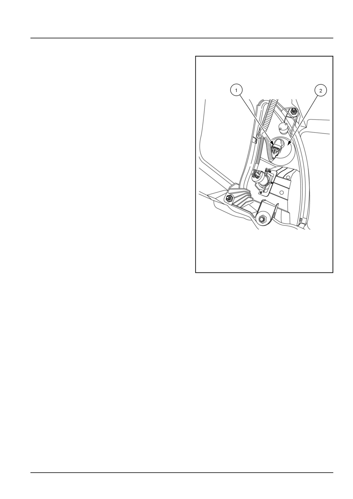
Headlight - Replace
1. Remove the electrical connector (1)
GNIL14TR00534AA
1
2. Remove the rubber boot (2)
3. Change a burned out bulb for another halogen bulb of
the same power
55.8 [55.404] / 3
Electrical systems - External lighting
Turn signal and/or hazard lights - Replace
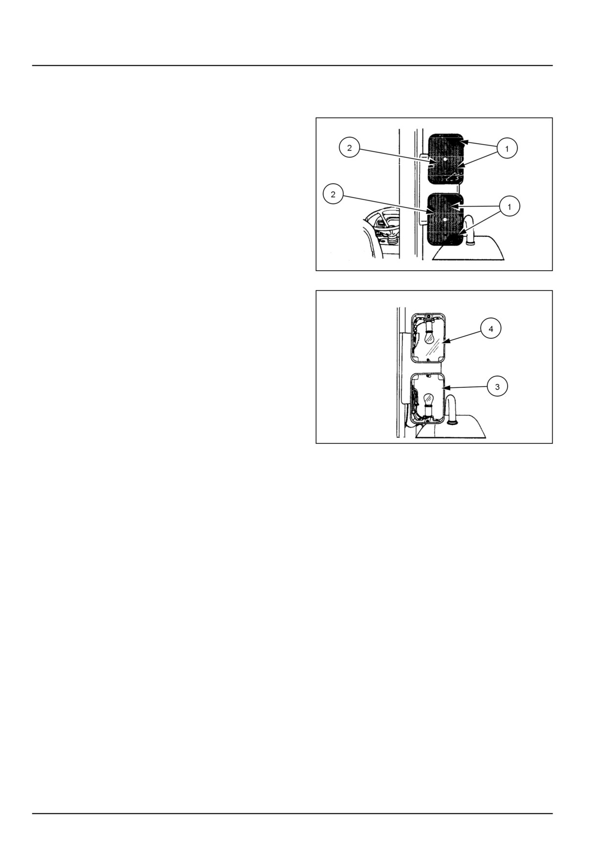
Stop/Turn/Position lights, bulb replacement
The bulbs are accessible after removal of the plastic
lenses assembly. Remove the two screws (1) and take
out the lens assembly (2). The bulbs can be removed
by pressing in and turning approximately 20 degree
counterclockwise. Reassemble in reverse order.
20108813
1
Tail light (3) and flasher/turn signal light (4)
NOTICE: When replacing the lenses, take care not to over-
tighten the retaining screws.
Bulb Size
• Tail Light - #1157
• Flasher/Turn Signal - #1156
20108814
2
55.8 [55.404] / 4
Electrical systems - External lighting
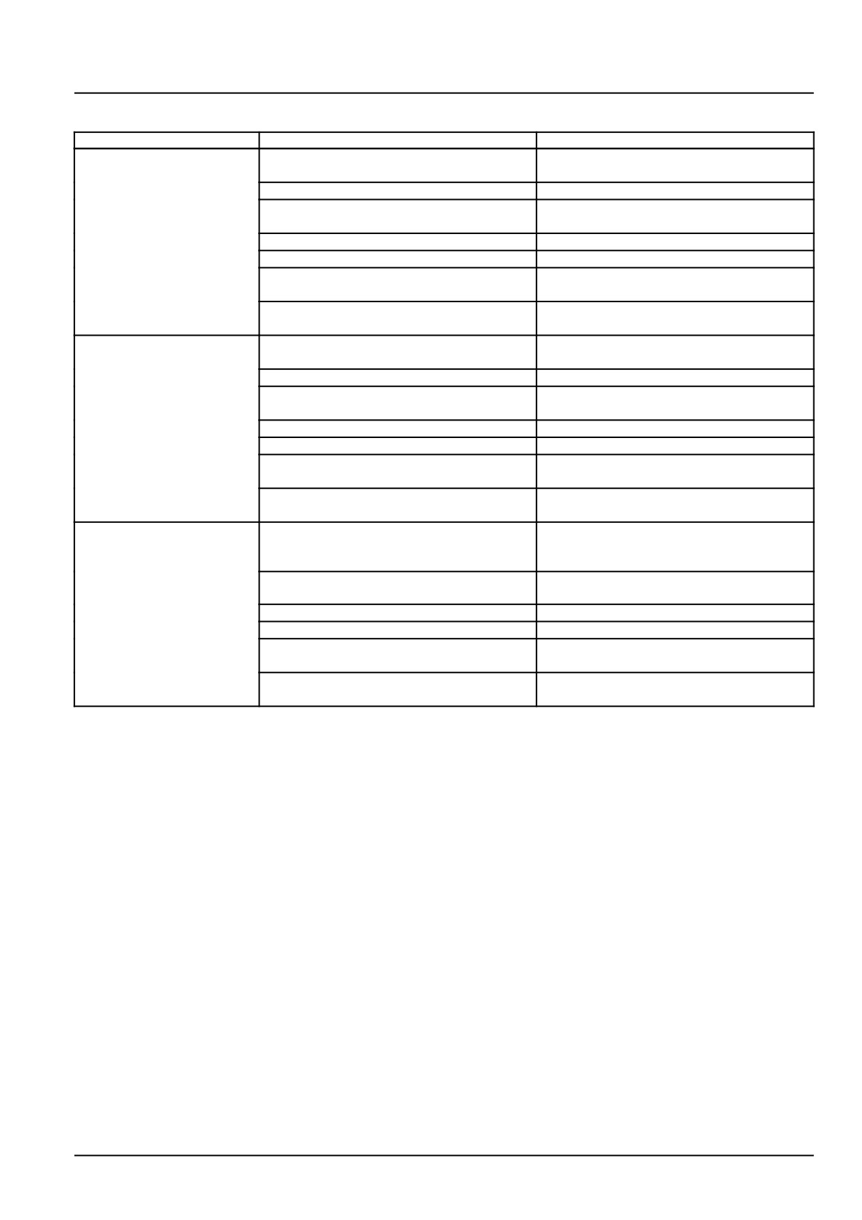
External lighting - Troubleshooting Lighting circuit
Problem
Possible Cause
Correction
Front road lamps will not
Insufficient battery charge.
Test battery. Charge, add water, or replace
illuminate or are dim
as necessary.
Road lamp bulb faulty.
Check and replace bulb as necessary.
Blown fusible link.
Inspect fusible link and replace as neces-
sary.
Blown fuse head/park, 20 A fuse.
Replace fuse as necessary.
Defective light switch.
Test light switch and replace as necessary.
Improper connection at work lamp termi-
Check connections and lamp socket. Re-
nals or headlight socket.
pair or replace as necessary.
Improper ground connection.
Check ground connections and repair as
necessary.
Rear taillights will not
Insufficient battery charge.
Test battery. Charge, add water, or replace
illuminate or are dim
as necessary.
Taillight bulb fault.
Check and replace bulb as necessary.
Blown fusible link.
Inspect fusible link and replace as neces-
sary.
Blown fuse head/park, 20 A fuse.
Replace fuse as necessary.
Defective light switch.
Test light switch and replace as necessary.
Improper connection at taillight lamp termi-
Check connections and lamp socket. Re-
nals or lamp socket.
pair or replace as necessary.
Improper ground connection.
Check ground connections and repair as
necessary.
Instrument panel
Insufficient battery charge.
Test battery. Charge, add water, or replace
illumination light not
as necessary.
illuminated or is dim
Instrument panel illumination bulb burnt
Check and replace bulb as necessary.
out.
Blown fuse head/park, 20 A fuse.
Replace fuse as necessary.
Defective light switch.
Test light switch and replace as necessary.
Improper connection at instrument panel
Check connections and socket. Repair or
terminals or light socket
replace as necessary.
Improper ground connection
Check ground connections and repair as
necessary.
55.8 [55.404] / 5
Electrical systems - External lighting
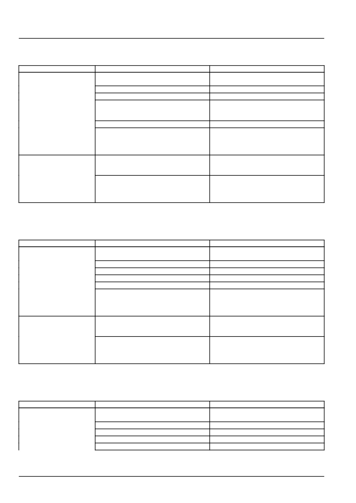
Turn signal and/or hazard lights - Troubleshooting Hazard lighting
circuit
Problem
Possible Cause
Correction
Hazard Signal Lights will
Blown fuse hazard,
15 A hazard signal
Inspect fuse and replace as necessary.
not illuminate or flash
fuse.
Hazard signal bulb(s) burnt out.
Inspect bulb(s) and replace as necessary.
Defective hazard switch.
Test switch and replace as necessary.
Defective flasher cutoff relay.
Test flasher relay by using a known func-
tioning flasher relay and replace as neces-
sary.
Defective hazard/turn flasher module.
Test module and replace as necessary.
Faulty wiring or ground connection.
Inspect the tractor's wiring harness and
ground terminals for damage, corrosion,
and short circuits. Repair or replace as
needed.
Instrument panel hazard
Indicator bulb(s) burnt out
Inspect bulb and replace as necessary
indicator( s) does not
illuminate
Faulty wiring or ground connection
Inspect the tractor s wiring harness and
ground terminals for damage, corrosion,
and short circuits. Repair or replace as
needed
Turn signal and/or hazard lights - Troubleshooting Right turn signal
circuit
Problem
Possible Cause
Correction
Directional signal will not
Blown fuse turn/horn, 15 A hazard or direc-
Inspect fuse and replace as necessary.
illuminate or flash
tional signal fuse.
Blown fuse hazard, 15 A fuse.
Inspect fuse and replace as necessary.
Directional signal bulb burnt out.
Inspect bulb and replace as necessary.
Defective directional signal switch.
Test switch and replace as necessary.
Defective hazard/turn flasher module.
Test module and replace as necessary.
Faulty wiring or ground connection.
Inspect the tractor's wiring harness and
ground terminals for damage, corrosion,
and short circuits. Repair or replace as
needed.
Instrument panel turn
Indicator bulb burnt out.
Inspect bulb and replace as necessary.
indicator does not
illuminate
Faulty wiring or ground connection.
Inspect the tractor's wiring harness and
ground terminals for damage, corrosion,
and short circuits. Repair or replace as
needed.
Turn signal and/or hazard lights - Troubleshooting Left turn signal
circuit
Problem
Possible Cause
Correction
Directional signal will not
Blown fuse turn/horn, 15 A hazard or direc-
Inspect fuse and replace as necessary.
illuminate or flash
tional signal fuse.
Blown fuse hazard, 15 A fuse.
Inspect fuse and replace as necessary.
Directional signal bulb burnt out.
Inspect bulb and replace as necessary.
Defective directional signal switch.
Test switch and replace as necessary.
Defective hazard/turn flasher module.
Test module and replace as necessary.
55.8 [55.404] / 6
Electrical systems - External lighting
Problem
Possible Cause
Correction
Faulty wiring or ground connection.
Inspect the tractor's wiring harness and
ground terminals for damage, corrosion,
and short circuits. Repair or replace as
needed.
Instrument panel turn
Indicator bulb burnt out.
Inspect bulb and replace as necessary.
indicator does not
illuminate
Faulty wiring or ground connection.
Inspect the tractor's wiring harness and
ground terminals for damage, corrosion,
and short circuits. Repair or replace as
needed.
55.8 [55.404] / 7
Index
Electrical systems - 55
External lighting - 404
External lighting - Troubleshooting Lighting circuit
5
Headlight - Replace
3
Turn signal and/or hazard lights - Replace
4
Turn signal and/or hazard lights - Troubleshooting Hazard lighting circuit
6
Turn signal and/or hazard lights - Troubleshooting Left turn signal circuit
6
Turn signal and/or hazard lights - Troubleshooting Right turn signal circuit
6
55.8 [55.404] / 8
Electrical systems - 55
External lighting switches and relays - 405
Workmaster™ 50
Workmaster™ 60
Workmaster™ 70
55.9 [55.405] / 1
Contents
Electrical systems - 55
External lighting switches and relays - 405
FUNCTIONAL DATA
Brake light switch
Overview
3
55.9 [55.405] / 2
Electrical systems - External lighting switches and relays
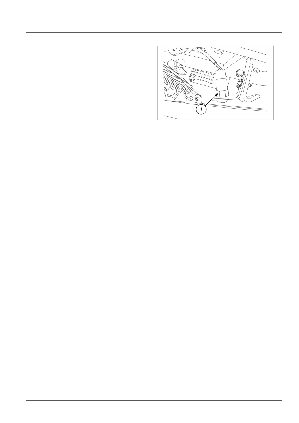
Brake light switch - Overview
The brake pedal switch (1) is located below the right foot
board near the foot brake. It is actuated while applying
brake and is indicated by the light provided on the fender.
GNIL14TR04724AB
1
55.9 [55.405] / 3
Index
Electrical systems - 55
External lighting switches and relays - 405
Brake light switch - Overview
3
55.9 [55.405] / 4
Electrical systems - 55
Warning indicators, alarms, and instruments - 408
Workmaster™ 50
Workmaster™ 60
Workmaster™ 70
55.10 [55.408] / 1
Contents
Electrical systems - 55
Warning indicators, alarms, and instruments - 408
FUNCTIONAL DATA
Warning indicators, alarms, and instruments
Overview
3
Instrument cluster
Overview
5
SERVICE
Instrument cluster
Remove
9
Install
12
DIAGNOSTIC
Instrument cluster
Troubleshooting
16
55.10 [55.408] / 2
Electrical systems - Warning indicators, alarms, and instruments
Warning indicators, alarms, and instruments - Overview
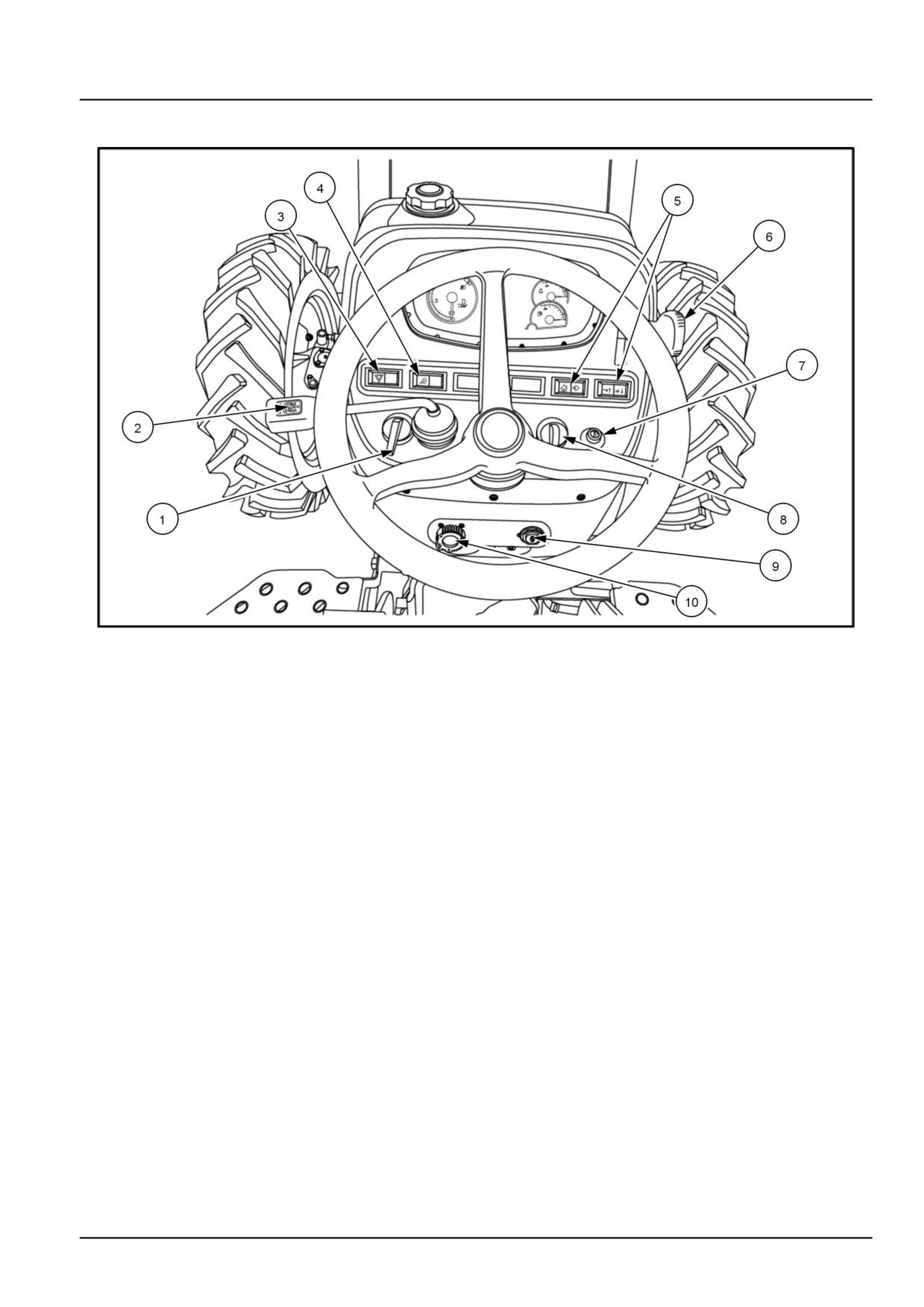
GNIL14TR00512AA
1
Turn signal switch
Turn signal switch (1) indicates turn signals and should be moved to the right to operate right turn indicator light and
left to operate left turn indicator light.
NOTE: The turn signal will operate only when the starter switch is turned on.
Shuttle shift lever
The shuttle shift lever (2) is used to change the direction of travel, between forward and reverse.
Hazard switch
The hazard switch (3) activates the hazard flasher lights. Use the hazard flasher lights when traveling on public roads,
day or night.
Head light switch
The head light switch (4) consists of four positions, (refer to Head Light Switch Positions).
Central display navigation buttons
The menus of the central liquid crystal display on the instrument panel are navigated through with the rocker switches
(5)
(A) and (B).
Hand throttle lever
The hand throttle lever (6) should be used during the field operation.
Push the lever up to increase the engine speed and down to reduce it.
55.10 [55.408] / 3
Electrical systems - Warning indicators, alarms, and instruments
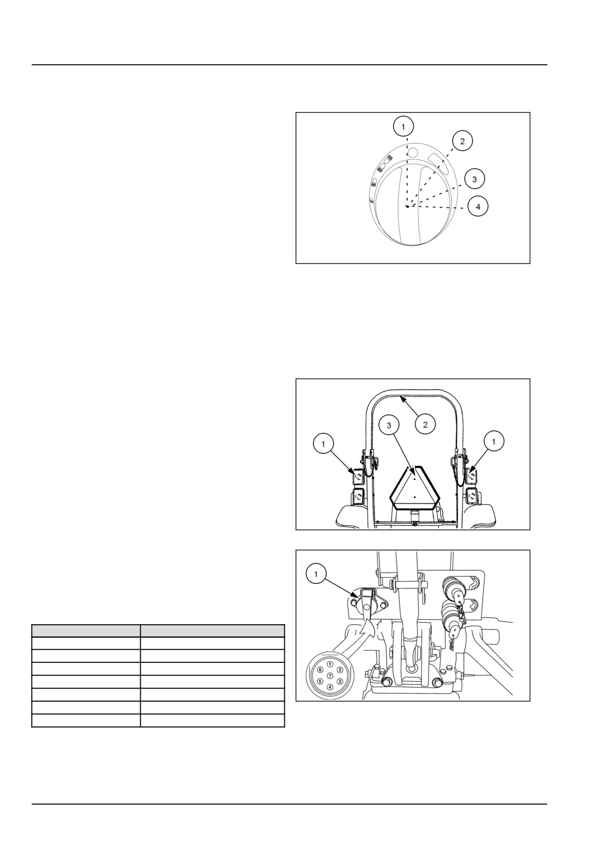
Horn Button
Press the horn button (7) for warning arrival
Head Light Switch Positions
The head light switch (8) consists of four positions,
Position (1)
- Off
Position (2)
- Parking lights on.
Position (3)
- Head lamp low beam.
Position (4)
- Head lamp high beam.
20108778
2
Key start/stop switch
The key start switch (9) activates electrical equipment, lights, gauges and starting motor.
Electronic service tool socket
The Electronic Service Tool (EST) socket (10) is used to connect the EST to the tractor.
Hazard warning light switch
The hazard warning lights switch (3) ( 1 ) activates the
hazard flashing warning lights (1) located on each side of
the ROPS (2).
The hazard flashing warning lights can be activated with
the key switch in any position. For your protection, use the
flasher warning lights and the SMV (Slow Moving Vehicle)
emblem (3) when travelling on public roads, day or night.
76099309N
3
Trailer electrical socket
A standard 7-pin trailer socket (1) is provided as standard
equipment and is mounted to the left side of ROPS cross
brace.
The socket pin connections (see insert) are as follows:
Pin No.
Circuit
1
Ground
2
Work Lights
3
Left Hazard Flasher Light
4
Current Input (not switched)
5
Right Hazard Flasher Light
6
Taillights
76099308N
4
7
Current Input (Switched)
55.10 [55.408] / 4
Electrical systems - Warning indicators, alarms, and instruments
Instrument cluster - Overview
GNIL14TR00509FA
1
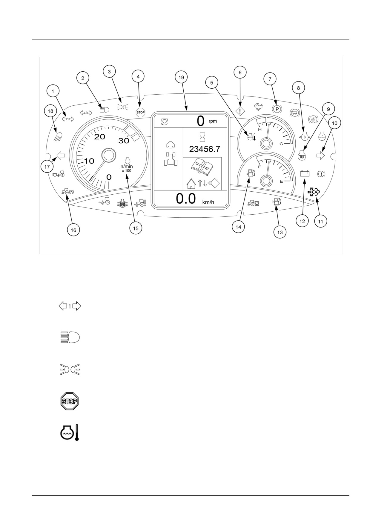
The indicator lights on the control panel inform you of the operational condition of the machine. Some of these indicate
faults arising during operation. An indicator light coming on may be followed by a continuous or intermittent buzzer.
Depending on the severity of the trouble, the alarm will sound.
Trailer direction indicator light (green)
1
This indicator light flashes together with the tractor/trailer direction indicators, if the first
trailer is connected
Full beam headlights (blue)
2
This indicator light will illuminate when the tractor lights are switched to high beam.
Side lights (green)
3
This indicator light is illuminated when the tractor lights are turned on.
Stop warning light (red)
4
If the red “Stop” warning light comes on, switch off the tractor immediately and look for the
cause. A warning symbol will appear on the display (30) confirming the location of the fault.
Engine coolant temperature gauge
5
This instrument indicates the temperature of the engine coolant.
55.10 [55.408] / 5
Electrical systems - Warning indicators, alarms, and instruments
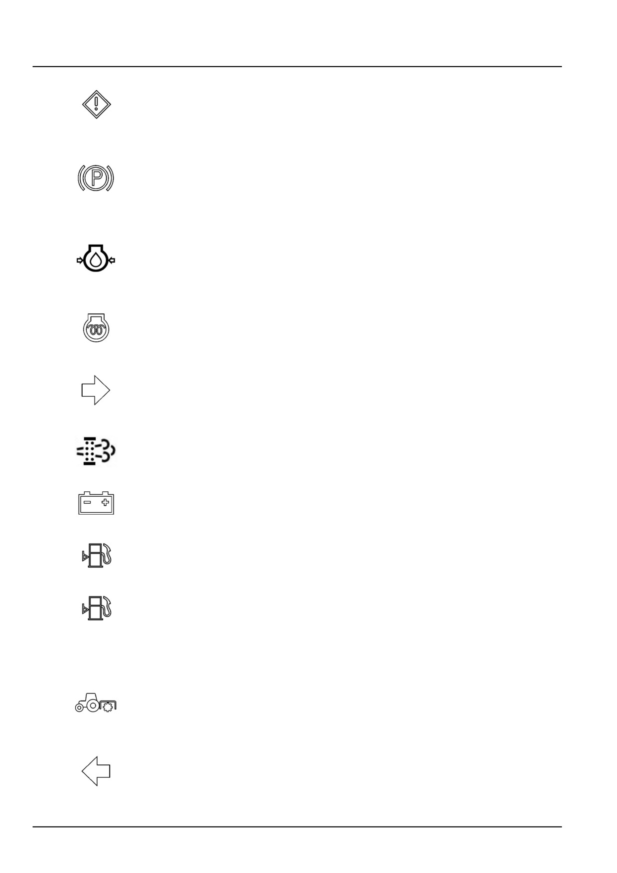
Indicator lamp (amber)
This indicator light comes on and the display shows a warning symbol (30). The light blinks
6
for 4 seconds, after which the symbol on the display disappears and the indicator light stays
on steady. To display the fault, you need to go to the menu. Stop the tractor and investigate
the cause of the trouble.
Parking brake warning light (red)
This lights up when the key start switch is turned ON with the parking brake applied. If the
7
key-start switch is turned OFF and the parking brake is not applied, or the operator leaves
the seat without applying the parking brake, a warning buzzer will sound for approximately 10
seconds or until the parking brake has been applied.
Engine oil pressure warning light (red)
Engine oil pressure indicator light (red) - This indicator light together with the red (5). ”Stop”
indicator light indicates the engine oil pressure is too low. Stop the engine and investigate
8
the cause.
NOTE: With low engine oil pressure, this warning light illuminates when the start switch is in
the contact position B (supply to accessories - ignition).
Cold start device (amber)
9
The indicator lights up when the glow plugs are turned on by the key start switch.
Right direction indicator (green)
This indicator light flashes at the same time as the tractor's right direction indicator. With the
10
tractor running, if the turn signal is not switched off within 20 seconds an intermittent alarm
comes on. This audible warning comes on if the direction indicator is not turned off within five
minutes with the tractor stationary.
Warning light of the Diesel Particulate Filter (DPF) (green)
11
For more details, see the chapter on regeneration of the particulate filter.
Alternator charging warning light (red)
12
A steady light indicates that the alternator is not charging the battery.
Fuel reserve (amber)
13
The light comes on when the tractor needs refuelling.
Fuel Level Gauge
14
This instrument shows the fuel level in the tank.
Revolution counter
15
Indicates the engine rpm. Each subdivision of the graduated scale represents 100 revs/minute.
Rear Power Take−Off (PTO) warning light (yellow)
Lights up when the engine is running and the rear power take-off is engaged.
16
The warning light, from being on steady, starts blinking when the power take−off exceeds
the maximum permissible number of revs.
Left direction indicator (green)
This indicator light flashes at the same time as the tractor's left direction indicator. With the
17
tractor running, if the turn signal is not switched off within 20 seconds an intermittent alarm
comes on. This audible warning comes on if the direction indicator is not turned off within five
minutes with the tractor stationary.
55.10 [55.408] / 6
Electrical systems - Warning indicators, alarms, and instruments
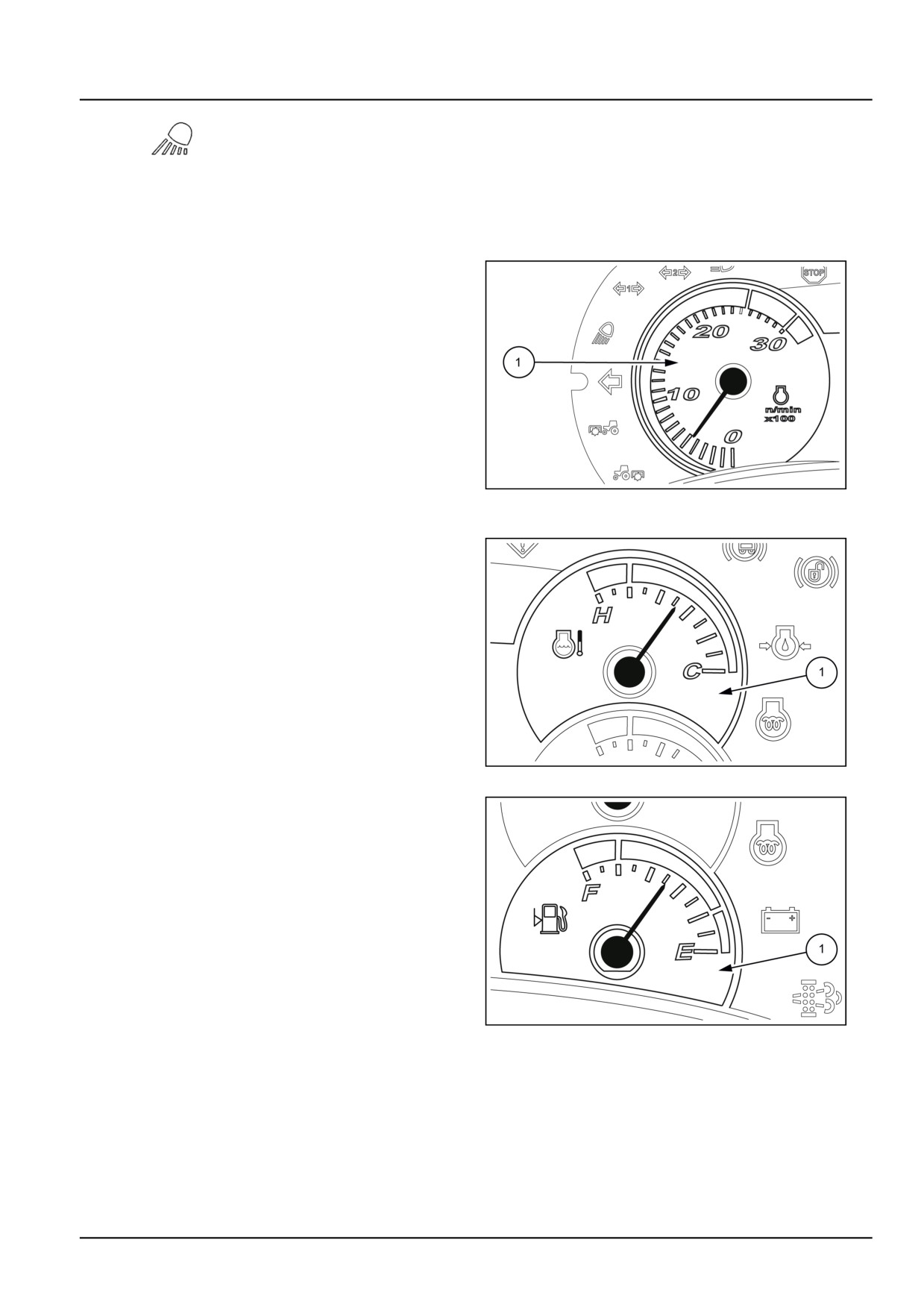
Work lights (amber)
18
This warning light illuminates when the work lights are switched on.
Information Display
19
The display shows information on the operational condition of the machine and highlights any
trouble in the form of symbols or error codes.
Rev counter/ Techometer
The rev counter (1) indicates the engine rpm. Each di-
vision on the scale represents 100 rev/min., therefore,
with the needle indicating 20 , the engine is running at
2000 RPM.
Engine speed
NOTICE: Never use the engine continuously for a long
time at speeds between 2500 - 3000 RPM (yellow area
on the speedometer) to avoid damage to the engine
and definitely never exceed
3000 RPM (red area on
the speedometer). For appropriate use, always operate
DCUTLBRNE003S3A
2
under the speed corresponding to 2300 RPM.
Engine coolant temperature gauge
The temperature display (1) indicates the temperature of
the engine coolant.
• blue area = normal temperature;
• red area = temperature too high.
In this case, slow the engine to idling speed (without stop-
ping the engine) and, if the light stays on, have the cooling
system checked.
DCUTLBRNE004S3A
3
Fuel level gauge
This instrument (1) indicates the level of diesel in the tank
and only works when the ignition key is turned onto ON.
DCUTLBRNE005S3A
4
55.10 [55.408] / 7
Electrical systems - Warning indicators, alarms, and instruments
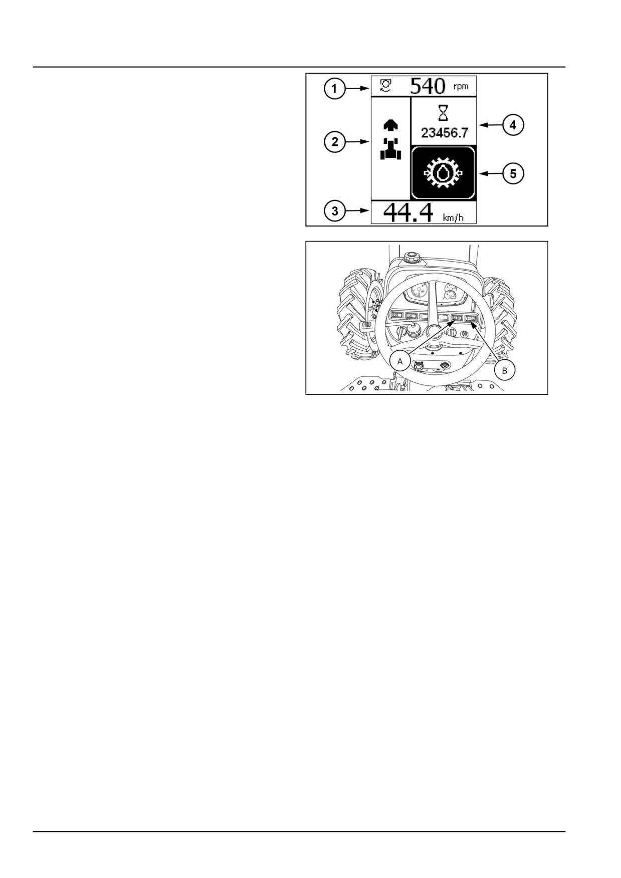
Central display
The central liquid crystal display provides the operator
with a range of information
• Front or rear power take−off speed
Front or rear lift position
Slip
Data displayed by pressing and releasing the button
ENTER (A)
• Tractor direction.
• Speed of the vehicle in Km/h or MPH
DCAPLT5NE005S3F
5
• Tractor working hour meter
• Kilometers travelled
Area worked
Area worked per hour
Battery voltage
Data displayed by pressing the arrow buttons up or
down (B)
When necessary, warning and error messages
Programming menu (see specific chapter)
GNIL14TR00512AA
6
55.10 [55.408] / 8
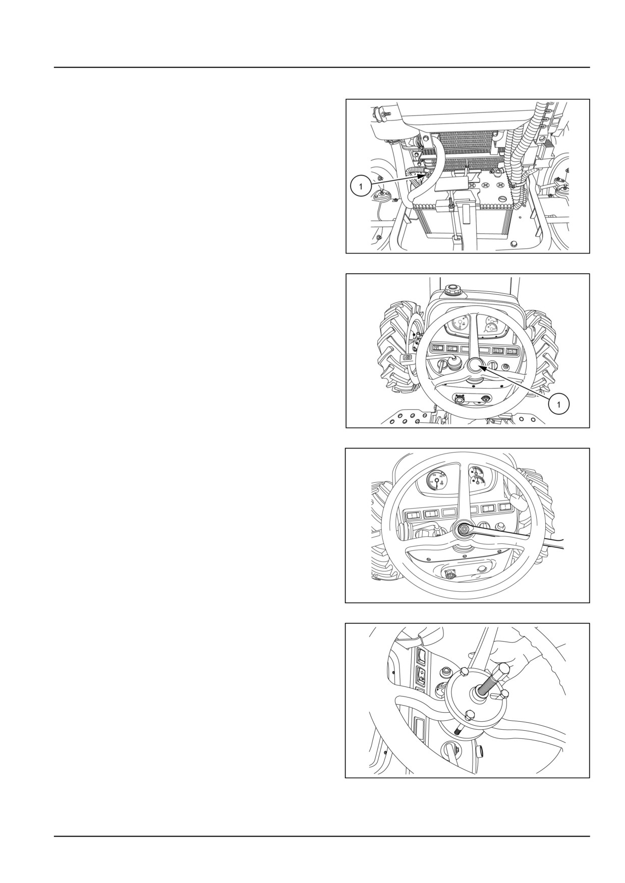
Electrical systems - Warning indicators, alarms, and instruments
Instrument cluster - Remove
1. Lift the front hood.
2. Disconnect battery terminals.
NOTE: Always disconnect the negative cable (1) first.
GNIL14TR00784AA
1
3. Remove the steering wheel cover (1).
GNIL14TR00512AA
2
4. Loosen the steering wheel securing nut.
GNIL14TR00846AA
3
5. Loosen the steering wheel securing nut and remove
the steering wheel using tool number 82834312 and
9971375.
GNIL14TR00704AA
4
55.10 [55.408] / 9
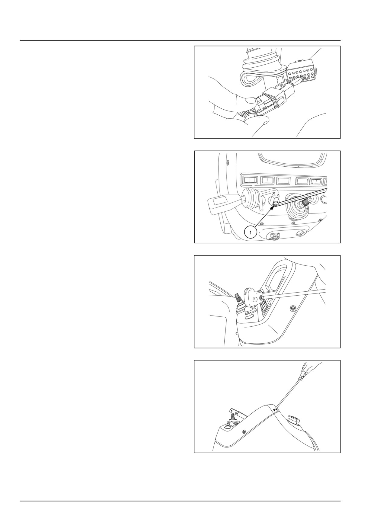
Electrical systems - Warning indicators, alarms, and instruments
6. Disconnect the wiring connection (1) near the steering
column.
GNIL14TR00711AA
5
7. Loosen the bolt (1) and remove the shuttle lever.
GNIL14TR00705AA
6
8. Remove the hand throttle knob.
GNIL14TR00706AA
7
9. Unscrew all the screws of instrument panel.
GNIL14TR00707AA
8
55.10 [55.408] / 10
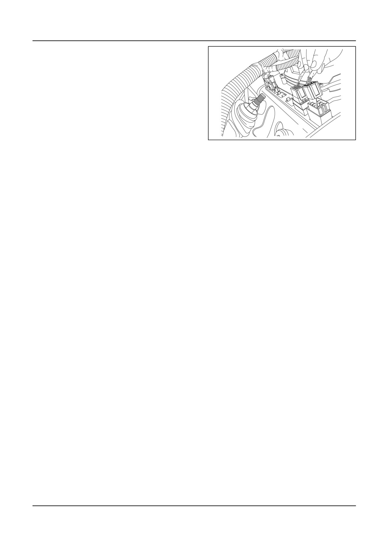
Electrical systems - Warning indicators, alarms, and instruments
10. Pull out the instrument panel from rear hood.
11. Disconnect all the electric connections of the switches
and hourmeter from the instrument cluster.
GNIL14TR00714AA
9
55.10 [55.408] / 11
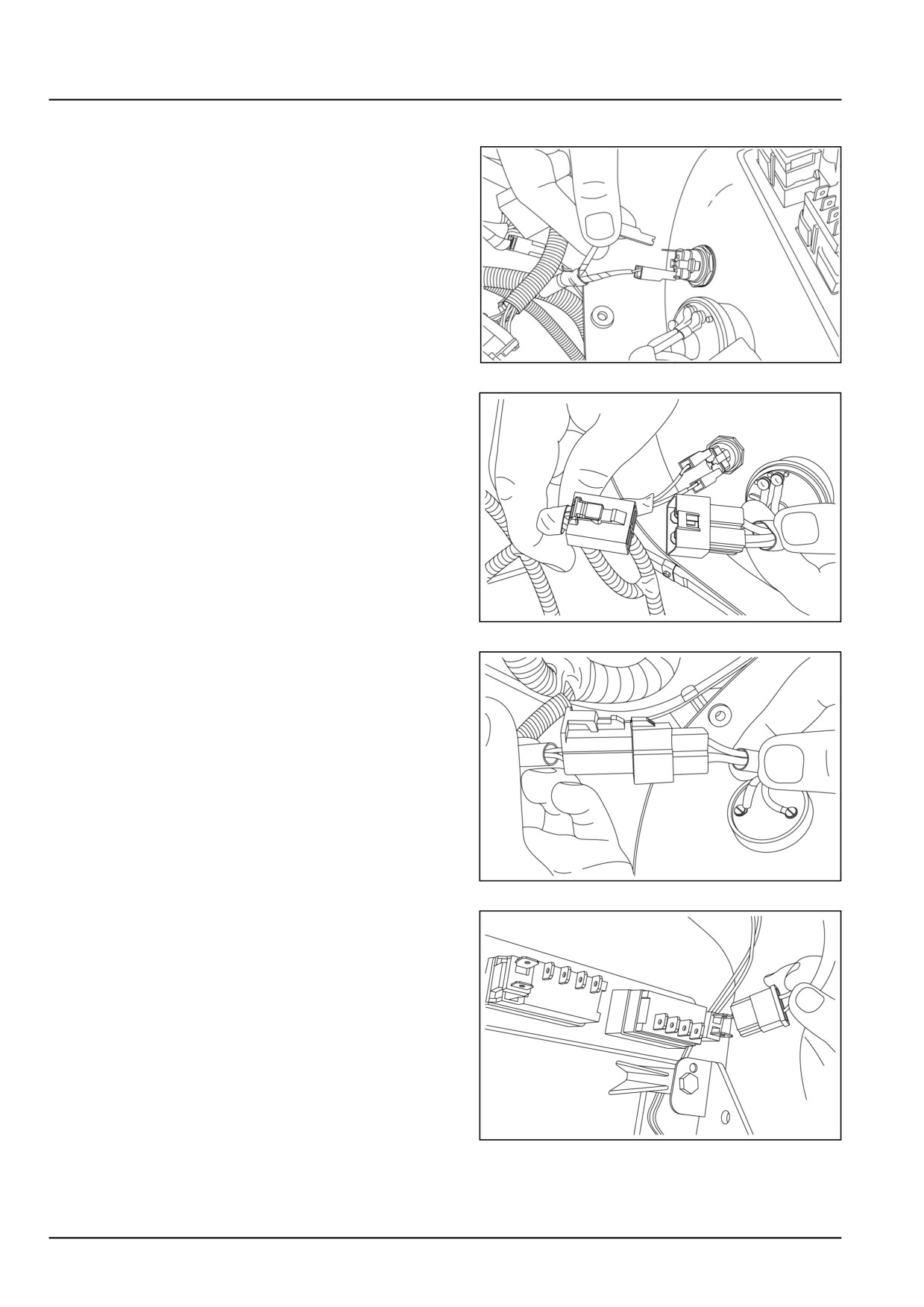
Electrical systems - Warning indicators, alarms, and instruments
Instrument cluster - Install
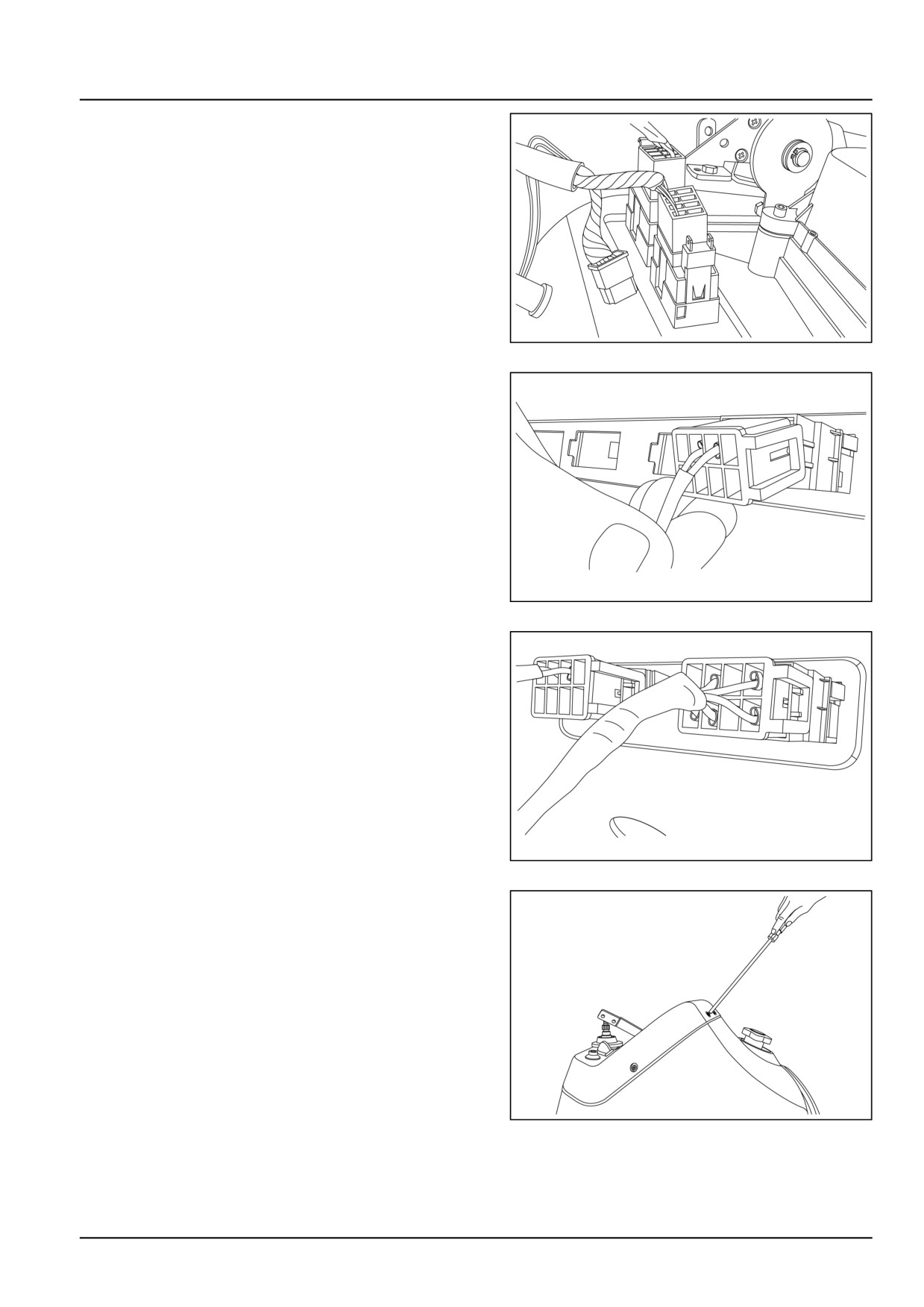
1. Connect wiring coupler to horn switch.
GNIL14TR00772AA
1
2. Connect wiring coupler to head light switch.
GNIL14TR00773AA
2
3. Connect wiring coupler to indicator switch.
GNIL14TR00774AA
3
4. Connect wiring coupler to programming arrow switch.
GNIL14TR00775AA
4
55.10 [55.408] / 12
Electrical systems - Warning indicators, alarms, and instruments
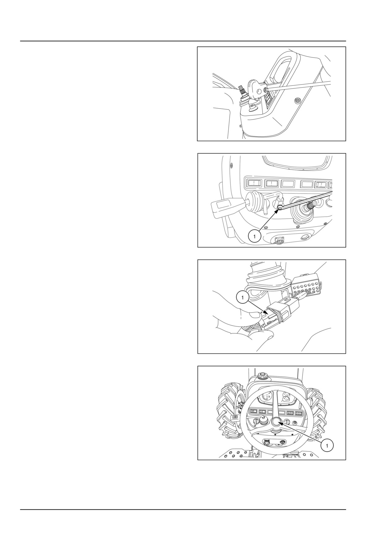
5. Connect wiring coupler to home programming switch.
GNIL14TR00776AA
5
6. Connect wiring coupler to Hi-Lo beam switch.
GNIL14TR00777AA
6
7. Connect wiring coupler to hazard warning switch.
GNIL14TR00778AA
7
8. Tighten all the screws (1) of instrument panel.
GNIL14TR00707AA
8
55.10 [55.408] / 13
Electrical systems - Warning indicators, alarms, and instruments
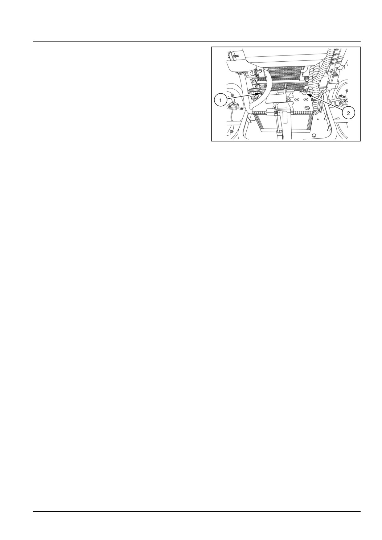
9. Fit the hand throttle knob.
GNIL14TR00706AA
9
10. Fit the shuttle lever and tighten the bolt (1).
GNIL14TR00705AA
10
11. Connect the wiring coupler (1) near the steering col-
umn.
GNIL14TR00711AA
11
12. Install the steering wheel and cover (1).
GNIL14TR00512AA
12
55.10 [55.408] / 14
Electrical systems - Warning indicators, alarms, and instruments
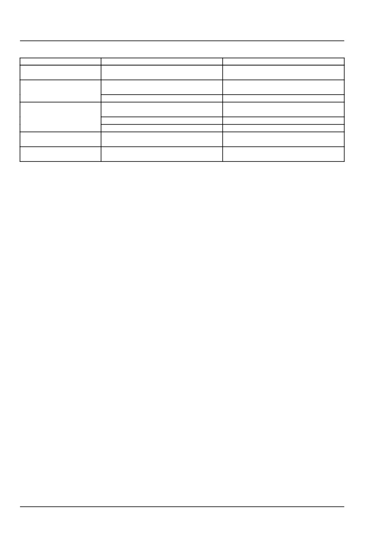
13. Connect the battery terminals (1) and (2).
GNIL14TR00784AA
13
55.10 [55.408] / 15
Electrical systems - Warning indicators, alarms, and instruments
Instrument cluster - Troubleshooting
Problem
Possible Cause
Correction
Warning lights and
Blown #6 15 A fuse.
Replace fuse.
gauges inoperative
Gauges erratic or
Faulty ground circuit.
Check ground connections for proper con-
inoperative
tact.
Faulty sender.
Check sender for proper operation.
Warning lights not
Bulb is burned out
Replace bulb
illuminating
Sender wire damaged
Check wiring harness for damage
Faulty sender
Check sender for proper operation
Gauges always show
Sender wire shorted to ground.
Check sender wire for damage.
maximum reading
Erratic tachometer
Fan belt slipping.
Tighten fan belt.
reading
55.10 [55.408] / 16
Index
Electrical systems - 55
Warning indicators, alarms, and instruments - 408
Instrument cluster - Install
12
Instrument cluster - Overview
5
Instrument cluster - Remove
9
Instrument cluster - Troubleshooting
16
Warning indicators, alarms, and instruments - Overview
3
55.10 [55.408] / 17
55.10 [55.408] / 18
Electrical systems - 55
Cab controls - 512
Workmaster™ 50
Workmaster™ 60
Workmaster™ 70
55.11 [55.512] / 1
Contents
Electrical systems - 55
Cab controls - 512
SERVICE
Joystick and Electric Hydraulic (EH) control
Remove
3
Install
5
55.11 [55.512] / 2
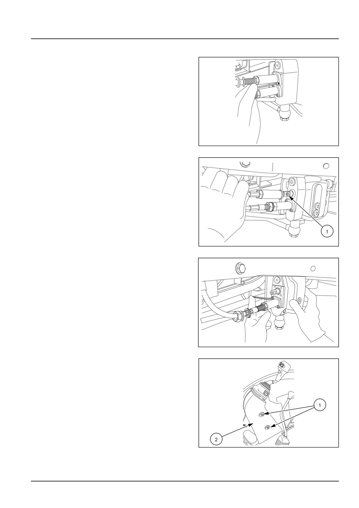
Electrical systems - Cab controls
Joystick and Electric Hydraulic (EH) control - Remove
1.
1. Loosen the locknut on joystick cable.
2. Loosen the set screws on the connectors of joystick
cable.
3. Slide the connector on the joystick cable.
GNIL14TR00764AA
1
2. Remove the roll pin (1) and remove the joystick cable.
GNIL14TR00821AA
2
3. Similarly remove the other joystick cable.
GNIL14TR00788AA
3
4. Loosen the screws (1) and remove the cover (2) of the
joystick.
GNIL14TR00786AA
4
55.11 [55.512] / 3
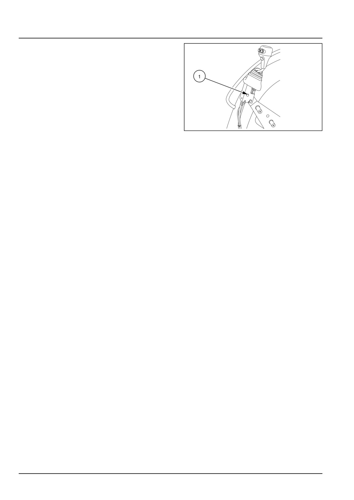
Electrical systems - Cab controls
5.
1. Disconnect the electrical coupling.
2. Loosen the bolts (1) and remove the joystick from
the mounting bracket.
GNIL14TR00787AA
5
55.11 [55.512] / 4

Electrical systems - Cab controls
Joystick and Electric Hydraulic (EH) control - Install
1. Install the joystick on the mounting bracket and tighten
the bolts (1).
Connect the electrical coupling.
GNIL14TR00787AA
1
2. Fit the cover (1) of the joystick and tighten the screws
(2).
GNIL14TR00786AA
2
3. Insert the roll-pin (1) and connect the joystick cable,
passing through the footboard, on the mid-mount valve.
NOTE: Connect the green colored cable on the upper port
of the mid-mount valve. Connect the yellow colored cable
on the lower port of the mid-mount valve.
GNIL14TR00821AA
3
4. Tighten the set screw (1) on the connector of the joy-
stick cable.
Tighten the locknut (2).
GNIL14TR00788AA
4
55.11 [55.512] / 5
Index
Electrical systems - 55
Cab controls - 512
Joystick and Electric Hydraulic (EH) control - Install
5
Joystick and Electric Hydraulic (EH) control - Remove
3
55.11 [55.512] / 6
Electrical systems - 55
FAULT CODES - DTC
Workmaster™ 50
Workmaster™ 60
Workmaster™ 70
1
Contents
Electrical systems - 55
FAULT CODES - DTC
DIAGNOSTIC
DTC
11C-02-Water in fuel sensor or sensor circuit failure [ECU]
8
DTC
11C-03-Water in fuel detected or water in fuel circuit failure [ECU]
10
DTC
131-03-Engine coolant temperature sensor voltage is higher than expected [ECU]
12
DTC
131-04-Engine coolant temperature sensor voltage is lower than expected [ECU]
14
DTC
133-03-Intake manifold temperature sensor voltage is higher than expected [ECU]
16
DTC
133-04-Intake manifold temperature sensor voltage is lower than expected [ECU]
18
DTC
134-00-Intake manifold pressure sensor drifted high [ECU]
20
DTC
134-01-Intake manifold pressure sensor drifted low [ECU]
21
DTC
134-03-Intake manifold pressure sensor voltage is higher than expected [ECU]
22
DTC
134-04-Intake manifold pressure sensor voltage is lower than expected [ECU]
24
DTC
135-03-Fuel temperature sensor voltage is higher than expected [ECU]
26
DTC
135-04-Fuel temperature sensor voltage is lower than expected [ECU]
28
DTC
136-03-Fuel rail pressure sensor voltage is higher than expected [ECU]
30
DTC
136-04-Fuel rail pressure sensor voltage is lower than expected [ECU]
32
DTC
137-02-Fuel pressure relief valve reached maximum allowed opening count [ECU]
34
DTC
137-03-Fuel pressure relief valve is open [ECU]
35
DTC
137-04-Fuel pressure relief valve is forced to open, perform pressure increase [ECU]
36
DTC
137-12-Averaged rail pressure is outside the expected tolerance range [ECU]
37
DTC
141-02-Crankshaft speed sensor values are not plausible [ECU]
38
DTC
141-04-Crankshaft speed sensor pattern is not plausible [ECU]
40
DTC
143-02-Camshaft speed sensor values are not plausible [ECU]
42
DTC
143-04-Camshaft speed sensor pattern is not plausible [ECU]
44
DTC
144-03-Compared camshaft and crankshaft speed sensor values are not plausible [ECU]
46
DTC
151-03-Fuel rail pressure has exceeded maximum positive deviation limits [ECU]
47
DTC
153-03-Fuel rail pressure has exceeded maximum negative deviation limits [ECU]
48
DTC
154-03-Fuel rail pressure has dropped below the minimum limit [ECU]
50
DTC
155-03-Fuel rail pressure has exceeded maximum limit [ECU]
51
DTC 157-03-High pressure pump fuel delivery quantity in over run exceeds a maximum threshold [ECU]53
DTC 158-03-Fuel pump pressure has exceeded desired pressure limits [ECU]
54
DTC 159-02-Fuel metering unit has an open load error [ECU]
55
DTC 15D-03-PMCat Inducement less severe derating level [ECU]
57
2
DTC
161-02-Short circuit error of injector in cylinder 1 [ECU]
58
DTC
161-03-Short circuit of low side to high source of injector in cylinder 1 [ECU]
61
DTC
162-02-Short circuit error of injector in cylinder 2 [ECU]
63
DTC
162-03-Short circuit of low side to high source of injector in cylinder 2 [ECU]
66
DTC
163-02-Short circuit error of injector in cylinder 3 [ECU]
68
DTC
163-03-Short circuit of low side to high source of injector in cylinder 3 [ECU]
71
DTC
167-02-Open load error of injector in cylinder 1 [ECU]
73
DTC
168-02-Open load error of injector in cylinder 2 [ECU]
75
DTC
169-02-Open load error of injector in cylinder 3 [ECU]
77
DTC
171-03-Injection bank 1 short circuit failure (all injectors of the same bank can be affected) [ECU]79
DTC
173-03-Injection bank 2 short circuit failure (all injectors of the same bank can be affected) [ECU]80
DTC
17C-12-ECU internal failure - Injector CY33x component [ECU]
82
DTC
17E-02-Number of desired injections exceeds threshold [ECU]
83
DTC
17E-03-Exceeded the number of injections for a given engine speed [ECU]
84
DTC
17E - 04-Injection control : Number of injections is limited by system [ECU]
85
DTC
17E-12-Number of injections is limited by quantity balance of high pressure pump [ECU]
86
DTC
17F-12-Missing adjustment value programming for injector in cylinder 1 [ECU]
87
DTC
18F-02-Lambda sensor heater power stage open circuit [ECU]
88
DTC
18F-03-Lambda sensor heater power stage short circuit to battery [ECU]
90
DTC
18F-04-Lambda sensor heater power stage short circuit to ground [ECU]
92
DTC
18F-04-Lambda sensor heater power stage short circuit to ground [ECU]
94
DTC
199-02-Turbocharger boost pressure is higher than expected [ECU]
96
DTC
199-02-Turbocharger boost pressure is higher than expected [ECU]
97
DTC
1B1-03-CAN A Bus off failure [ECU]
98
DTC
1B1-04-CAN A Bus off passive failure [ECU]
100
DTC
1B5-02-CAN communication error between vehicle controller to ECU [ECU]
102
DTC
1B7-02-CAN transmit error - EEC1 message (Electronic Engine Control 1 message - Torque, accel-
erator pedal, engine speed, and other signals) [ECU]
104
DTC 1C6-03-CAN communication failure between vehicle controller and ECU controller - TSC1_PE mes-
sage [ECU]
106
DTC 1C8-03-CAN communication failure between vehicle controller and ECU controller - TSC1_VE mes-
sage [ECU]
108
DTC 1D1-03-ECU internal failure [ECU]
110
DTC 1D2-02-ECU internal failure - EEPROM write error [ECU]
111
DTC 1D2-03-ECU internal failure - EEPROM erase error [ECU]
112
DTC 1D2-04-ECU internal failure - EEPROM read error [ECU]
113
DTC 1D2-12-ECU internal failure - EEPROM write/read error [ECU]
114
DTC 1D3-12-ECU internal failure - Software resets in DSM 0 [ECU]
115
DTC 1D4-12-ECU internal failure - Query/response communication errors [ECU]
116
DTC 1D8-12-ECU internal failure - SPI communication error [ECU]
117
DTC 1D9-02-ECU internal failure - ADC test [ECU]
118
DTC 1D9-03-ECU internal failure - Voltage ratio in ADC monitoring [ECU]
119
DTC 1D9-12-ECU internal failure - NTP error in ADC monitoring [ECU]
120
3
DTC
1DA-12-ECU internal failure - Fuel calibration [ECU]
121
DTC
1E1-03-Starter relay high side driver circuit shorted to battery [ECU]
122
DTC
1E1-04-Starter relay high side driver circuit shorted to ground [ECU]
124
DTC
1E3-03-Fuel injection requested during overrun [ECU]
126
DTC
1E4-03-ECU internal failure - Calculated engine speed [ECU]
127
DTC
1E6-12-ECU 5 volt sensor supply 1 out of range [ECU]
128
DTC
1E7-03-ECU 5 volt sensor supply 2 out of range [ECU]
132
DTC
1E8-03-ECU 5 volt sensor supply 3 out of range [ECU]
134
DTC
1EB-03-ECU internal failure - Ambient pressure sensor voltage is higher than expected [ECU] .
136
DTC
1EB-04-ECU internal failure - Ambient pressure sensor voltage is lower than expected [ECU] . .
137
DTC
1F7-00-PMCat inlet temperature sensor physical range check high [ECU]
138
DTC
1F7-03-PMCat inlet temperature sensor voltage is higher than expected [ECU]
140
DTC
1F7-04-PMCat inlet temperature sensor voltage is lower than expected [ECU]
142
DTC
225-03-Main relay stuck error [ECU]
144
DTC
225-03-Main relay stuck error [ECU]
146
DTC
226-03-Battery voltage is higher than expected [ECU]
149
DTC
226-04-Battery voltage is lower than expected [ECU]
150
DTC
236-03-Rail pressure sensor value is above maximum offset [ECU]
152
DTC
236-03-Rail pressure sensor value is above maximum offset [ECU]
153
DTC
236-04-Rail pressure sensor value is below minimum offset [ECU]
154
DTC
237-04-Fuel pressure relief valve is forced to open, perform pressure shock [ECU]
155
DTC
237-04-Fuel pressure relief valve is forced to open, perform pressure shock [ECU]
156
DTC
237-12-Quantity balance check if a successful PRV opening is ensured [ECU]
157
DTC
237-12-Quantity balance check if a successful PRV opening is ensured [ECU]
158
DTC
238-03-Oil pressure switch active with engine off [ECU]
159
DTC
238-04-Low oil pressure [ECU]
161
DTC
256-03-Engine speed limitation via fuel injection cut off is active [ECU]
163
DTC
259-03-Fuel metering unit is shorted to battery voltage at the low side [ECU]
164
DTC
25A-03-Error in comparing energizing time to maximum value for injector in cylinder 1 [ECU] . .
166
DTC
25A-04-Error in comparing energizing time to minimum value for injector in cylinder 1 [ECU] . . .
167
DTC
25D-03-PMCat Inducement most severe derating level [ECU]
168
DTC
26F-04-The minimum rail pressure value necessary to allow fuel injection has not been reached
[ECU]
169
DTC 27F-12-Missing adjustment value programming for injector in cylinder 2 [ECU]
170
DTC 299-04-Turbocharger boost pressure is lower than expected [ECU]
171
DTC 2B4-02-CAN communication failure between vehicle controller and ECU - BC2ECU2 message
[ECU]
172
DTC 2C6-02-CAN communication failure between vehicle controller and ECU controller - TSC1_PE mes-
sage [ECU]
174
DTC 2CC-00-Engine controller internal temperature out of range (High) [ECU]
176
DTC 2CC-01-Engine controller internal temperature out of range (Low) [ECU]
177
DTC 2CC-12-Engine controller internal temperature out of range (SPI Error - LM71) [ECU]
178
DTC 2D1-03-ECU internal failure - Error on R2S2 module [ECU]
179
4