New Holland Tractor Workmaster 50 / Workmaster 60 / Workmaster 70 / Tier 4B (final). SERVICE MANUAL - page 16
Electrical systems - Harnesses and connectors
Wire connectors - Component diagram 10 - Connectors X-9101 to
X-9109
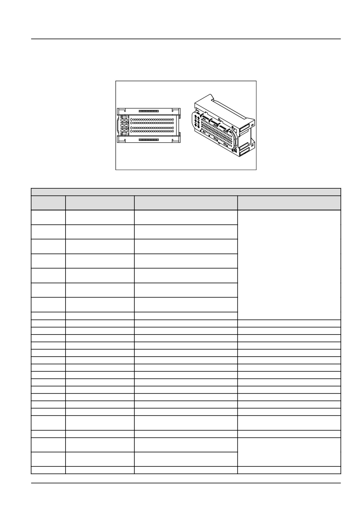
Connector X-9102 - Engine Control Unit (ECU) connector K
84474047
1
84474047
CONNECTOR X-9102 - ECU connector K
PIN
WIRE NUMBER
CIRCUIT REFERENCE
ELECTRICAL SCHEMATIC FRAME
NUMBER
K01
VE-9083
Main relay switched fused supply,
SHEET
02
independent source
K02
VE-9210
Ground, Battery minus (negative)
terminal
K03
VE-9079
Main relay switched fused supply,
shared source (K05)
K04
VE-9211
Ground, Battery minus (negative)
terminal
K05
VE-9076
Main relay switched fused supply,
shared source (K03)
K06
VE-9212
Ground, Battery minus (negative)
terminal
K07
VE-9200
Low Side Driver (LSD), DEF/AdBlue®
tank heating valve
K08
VE-9048
Input signal, Key switch start position
K09
-
-
K10
-
-
K11
-
-
K12
-
-
K13
-
-
K14
-
-
K15
-
-
K16
-
-
K17
-
-
K18
-
-
K19
-
-
K20
-
-
K21
-
-
K22
VE-9073
Input signal, Glow-plug Control Unit
SHEET
02
(GCU) feedback
K23
-
-
K24
VE-####
CAN 1 High, Diagnostic and
SHEET
02
maintenance connector
K25
VE-####
CAN 1 Low, Diagnostic and
maintenance connector
K26
-
-
55.4 [55.100] / 81
Electrical systems - Harnesses and connectors
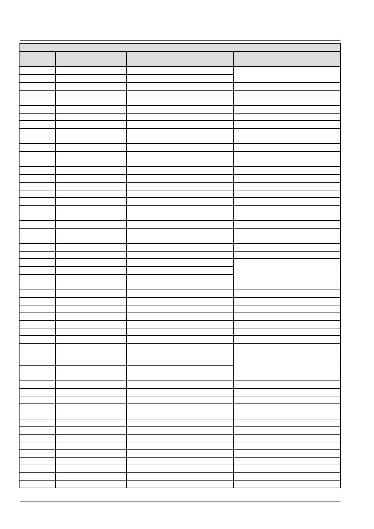
CONNECTOR X-9102 - ECU connector K
PIN
WIRE NUMBER
CIRCUIT REFERENCE
ELECTRICAL SCHEMATIC FRAME
NUMBER
K27
VE-9174
LSD, Starter control relay
SHEET
02
K28
VE-9084
LSD, Main relay
K29
-
-
K30
-
-
K31
-
-
k32
-
-
K33
-
-
K34
-
-
K35
-
-
K36
-
-
K37
K38
K39
-
-
K40
-
-
K41
VE-9074
Reference ground, GCU
SHEET
02
K42
-
-
K43
-
-
K44
-
-
K45
-
-
K46
-
-
K47
-
-
K48
-
-
K49
-
-
K50
-
-
K51
-
-
K52
VE-9072
LSD, GCU
SHEET
02
K53
VE-9173
HSD, Starter control relay
K54
VE-9053
Input signal, Key switch ON/ACC
position
K55
-
-
K56
-
-
K57
-
-
K58
-
-
K59
-
-
K60
-
-
K61
-
-
K62
-
-
K63
VE-9156
Input signal, Lambda sensor voltage
SHEET
02
nernst
K64
VE-9154
Input signal, Lambda sensor current
pump
K65
-
-
K66
-
-
K67
-
-
K68
ISO-K Interface, Diagnostic and
SHEET
02
monitoring connector K-line
K69
-
-
K70
-
-
K71
-
-
K72
-
-
K73
-
-
K74
-
-
K75
-
-
K76
-
-
K77
-
-
55.4 [55.100] / 82
Electrical systems - Harnesses and connectors
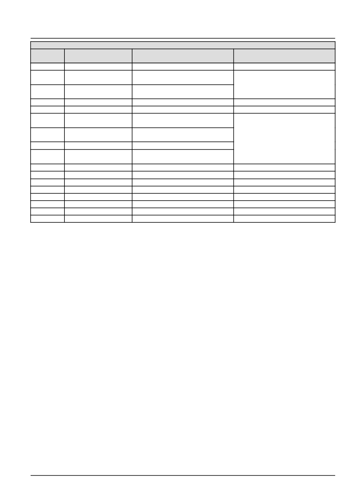
CONNECTOR X-9102 - ECU connector K
PIN
WIRE NUMBER
CIRCUIT REFERENCE
ELECTRICAL SCHEMATIC FRAME
NUMBER
K78
-
-
K79
VE-9188
Reference ground, Exhaust gas
SHEET 02
temperature DOC sensor
K80
VE-9147
Input signal, Exhaust gas temperature
DOC sensor
K81
-
-
K82
-
-
K83
VE-9153
Reference ground, Exhaust gas
SHEET 02
temperature POC sensor
K84
VE-9152
Input signal, Exhaust gas temperature
POC sensor
K85
VE-9155
Reference ground, Lambda sensor
K86
VE-9157
Input signal, Lambda sensor current
adjust
K87
-
-
K88
VE-9077
Input signal, Water in fuel switch
SHEET 02
K89
-
-
K90
-
-
K91
-
-
K92
-
-
K93
-
-
K94
-
-
55.4 [55.100] / 83
Electrical systems - Harnesses and connectors
Wire connectors - Component diagram 11 - Connectors X-9110 to
X-9119
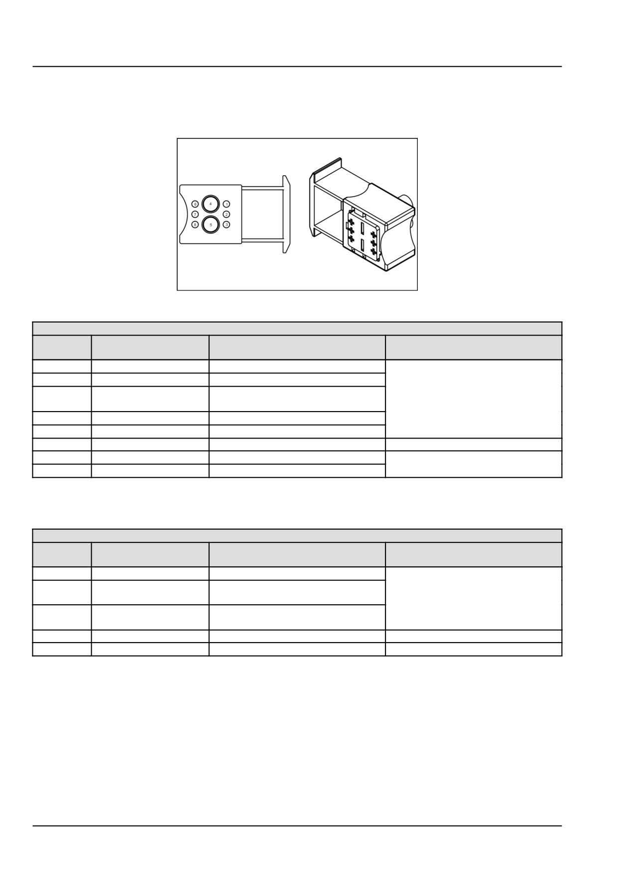
Connector X-9113 - Glow-plugs control unit
84356962
1
84356962
CONNECTOR X-9113 - Glow-plugs control unit
PIN
WIRE NUMBER
CIRCUIT REFERENCE
ELECTRICAL SCHEMATIC FRAME
NUMBER
1
VE-9060
High Side Driver (HSD), Glow-plug 3
SHEET 01
2
VE-9058
High Side Driver (HSD), Glow-plug 1
3
VE-9073
Feedback signal, Engine Control Unit
(ECU)
4
VE-9062
12 V Supply, Battery positive
5
VE-9074
Reference ground, ECU
6
-
-
7
VE-9059
High Side Driver (HSD), Glow-plug 2
SHEET 01
8
VE-9072
Control signal, ECU
Connector X-9116 - Engine shut-off relay
NOTE: Relays are in product relay panels. See product service manual for pinout image of this connector.
CONNECTOR X-9116 - Engine shut-off relay
PIN
WIRE NUMBER
CIRCUIT REFERENCE
ELECTRICAL SCHEMATIC FRAME
NUMBER
85
VE-9089
Switched battery voltage, Power relay
SHEET 02
86
VE-####
Low side control, Operator safety
module
30
VE-9053
Key switch signal (T50), Engine
Control Unit (ECU)
87A
-
-
87
VE-9088, VE-9089
Switched battery voltage, Power relay
SHEET 02
55.4 [55.100] / 84
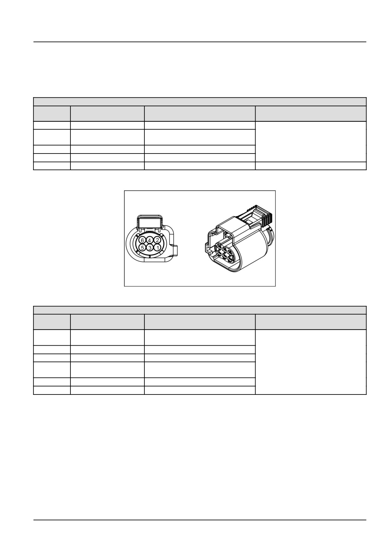
Electrical systems - Harnesses and connectors
Wire connectors - Component diagram 12 - Connectors X-9120 to
X-9129
Connector X-9120 - ECU start relay
NOTE: Relays are in product relay panels. See product service manual for pinout image of this connector.
CONNECTOR X-9120 - ECU start relay
PIN
WIRE NUMBER
CIRCUIT REFERENCE
ELECTRICAL SCHEMATIC FRAME
NUMBER
30
VE-####
Switched 12 V source, Neutral switch
SHEET 01
85
VE-9174
Low side switched control, Engine
Control Unit (ECU)
86
VE-9173
High side switched control, ECU
87
VE-####
High side control, Crank relay
87A
-
-
Connector X-9123 - Lambda sensor
84301132
1
84301132
CONNECTOR X-9123 - Lambda sensor
PIN
WIRE NUMBER
CIRCUIT REFERENCE
ELECTRICAL SCHEMATIC FRAME
NUMBER
1
VE-9154
Current pump input, Engine Control
SHEET 02
Unit (ECU)
2
VE-9155
Reference ground, ECU
3
VE-9200
Low side switched control, ECU
4
VE-9081
Switched 12 V source, Main ECU
power relay
5
VE-9157
Current adjust input, ECU
6
VE-9156
Nernst voltage input, ECU
55.4 [55.100] / 85
Electrical systems - Harnesses and connectors
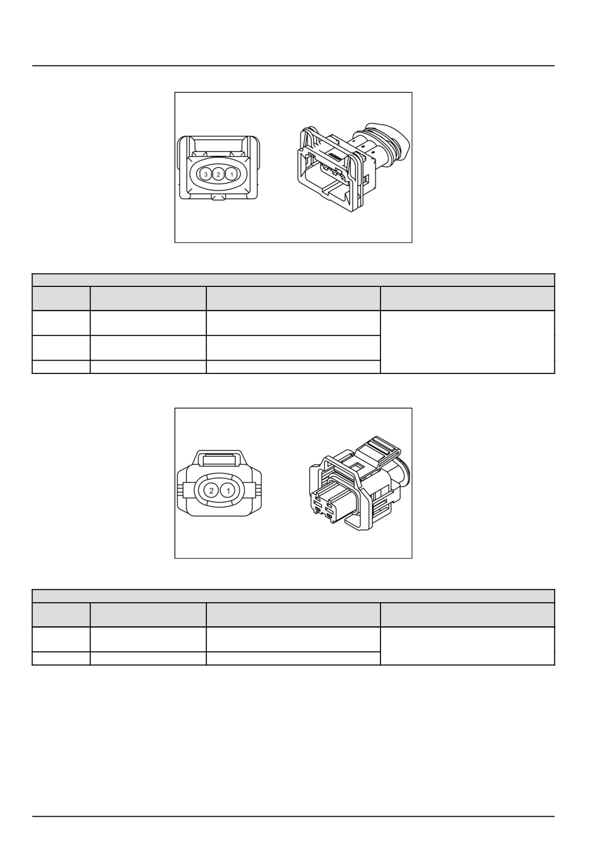
Connector X-9125 - Water in fuel sensor
84806091
2
84806091
CONNECTOR X-9125 - Water in fuel sensor
PIN
WIRE NUMBER
CIRCUIT REFERENCE
ELECTRICAL SCHEMATIC FRAME
NUMBER
1
VE-9077
Input signal, Engine Control Unit
SHEET 02
(ECU)
2
VE-9085
Switched source voltage, Main ECU
power relay
3
VE-9078
Frame ground
Connector X-9126 - Exhaust gas temperature Diesel Oxidation Catalyst (DOC) sensor
87709793
3
87709793
CONNECTOR X-9126 - Exhaust gas temperature DOC sensor
PIN
WIRE NUMBER
CIRCUIT REFERENCE
ELECTRICAL SCHEMATIC FRAME
NUMBER
1
VE-9147
Input signal, Engine Control Unit
SHEET 02
(ECU)
2
VE-9188
Reference ground, ECU
55.4 [55.100] / 86
Electrical systems - Harnesses and connectors
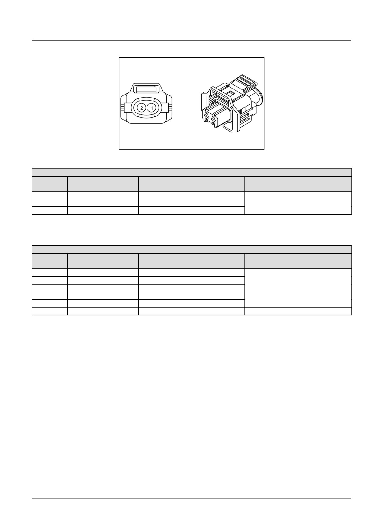
Connector X-9127 - Exhaust gas temperature Pre-Oxidation Catalyst (POC) sensor
87709793
4
87709793
CONNECTOR X-9127 - Exhaust gas temperature POC sensor
PIN
WIRE NUMBER
CIRCUIT REFERENCE
ELECTRICAL SCHEMATIC FRAME
NUMBER
1
VE-9152
Input signal, Engine Control Unit
SHEET 02
(ECU)
2
VE-9153
Reference ground, ECU
Connector X-9129 - Main ECU power relay
NOTE: Relays are in product relay panels. See product service manual for pinout image of this connector.
CONNECTOR X-9129 - Main ECU power relay
PIN
WIRE NUMBER
CIRCUIT REFERENCE
ELECTRICAL SCHEMATIC FRAME
NUMBER
30
VE-9087, VE-9086
12 V source, Battery positive
SHEET 02
85
VE-9086
12 V source, battery positive
86
VE-9084
Low side switched control, Engine
Control Unit (ECU)
87
VE-9082
Controlled source, fuse panel
87A
-
-
55.4 [55.100] / 87
Electrical systems - Harnesses and connectors
Electrical components - Fuse description
F-001 - MEGA FUSE (Fuse)
Component Type
Fuse
Wiring frames
SHEET 03
Connectors
X-015 (Male)
X-017 (Male)
F-002 - GEP - FUSE BOX (Fuse)
Component Type
Fuse
Wiring frames
SHEET
02
SHEET
04
SHEET
05
SHEET
09
F-003 - FUSE ECU 01 (Fuse)
Component Type
Fuse
Wiring frames
SHEET
02
SHEET
06
F-004 - FUSE ECU 02 (Fuse)
Component Type
Fuse
Wiring frames
SHEET
02
F-005 - LAMBDA PROBES (Fuse)
Component Type
Fuse
Wiring frames
SHEET
02
F-006 - CLUSTER HOT (Fuse)
Component Type
Fuse
Wiring frames
SHEET
02
F-007 - WORK LAMP (Fuse)
Component Type
Fuse
Wiring frames
SHEET
02
F-008 - HIGH/LOW BEAM (Fuse)
Component Type
Fuse
Wiring frames
SHEET
02
F-009 - STARTER SWITCH (Fuse)
Component Type
Fuse
Wiring frames
SHEET
02
F-010 - HEATER (Fuse)
Component Type
Fuse
Wiring frames
SHEET
02
F-011 - LOADER (Fuse)
Component Type
Fuse
Wiring frames
SHEET
02
47866583_
02/12/2015
55.4 [55.100] / 88
Electrical systems - Harnesses and connectors
F-012 - ECU/SAFETY START (Fuse)
Component Type
Fuse
Wiring frames
SHEET
02
F-013 - DUMMY1 (Fuse)
Component Type
Fuse
Wiring frames
SHEET
02
F-014 - DUMMY2 (Fuse)
Component Type
Fuse
Wiring frames
SHEET
02
F-015 - FLASHER (Fuse)
Component Type
Fuse
Wiring frames
SHEET
06
F-016 - CLUSTER / FT (Fuse)
Component Type
Fuse
Wiring frames
SHEET
06
F-017 - HAZARD HOT (Fuse)
Component Type
Fuse
Wiring frames
SHEET
06
F-018 - HORN/ LIGHT SW (Fuse)
Component Type
Fuse
Wiring frames
SHEET
06
F-019 - SAFETY LOGIC (Fuse)
Component Type
Fuse
Wiring frames
SHEET
06
F-020 - BECON LAMP (Fuse)
Component Type
Fuse
Wiring frames
SHEET
06
Electrical systems - Harnesses and connectors
Electrical components - Voltage source description
G-001 - BATTERY (Voltage source)
Component Type
Voltage source
Wiring frames
SHEET 03
Connectors
X-001A (Male)
X-001B (Male)
G-002 - ALTERNATOR (Voltage source)
Component Type
Voltage source
Wiring frames
SHEET 03
Connectors
X-209 (Male)
55.4 [55.100] / 90
Electrical systems - Harnesses and connectors
Electrical components - Relay description
K-001 - ECU POWER (Relay)
Component Type
Relay
Wiring frames
SHEET
02
K-002 - CRANKING RELAY (Relay)
Component Type
Relay
Wiring frames
SHEET
02
K-003 - ING RELAY 01 (Relay)
Component Type
Relay
Wiring frames
SHEET
04
K-004 - ING RELAY 02 (Relay)
Component Type
Relay
Wiring frames
SHEET
04
K-005 - W LAMP (Relay)
Component Type
Relay
Wiring frames
SHEET
04
K-006 - HIGH BEAM (Relay)
Component Type
Relay
Wiring frames
SHEET
04
K-007 - LOW BEAM (Relay)
Component Type
Relay
Wiring frames
SHEET
04
K-008 - PTO SAFETY START (Relay)
Component Type
Relay
Wiring frames
SHEET 04
K-009 - STOP LIGHT (Relay)
Component Type
Relay
Wiring frames
SHEET 04
K-010 - ENGINE SHUT-OFF (Relay)
Component Type
Relay
Wiring frames
SHEET 04
K-011 - SAFETY RUN (Relay)
Component Type
Relay
Wiring frames
SHEET 04
K-012 - CRANK PROTECTION (Relay)
Component Type
Relay
Wiring frames
SHEET 04
55.4 [55.100] / 91
Electrical systems - Harnesses and connectors
K-013 - FRONT LOADER (Relay)
Component Type
Relay
Wiring frames
SHEET 02
K-014 - HEATER (Relay)
Component Type
Relay
Wiring frames
SHEET 02
55.4 [55.100] / 92
Electrical systems - Harnesses and connectors
Electrical components - Motor description
M-001 - STARTER MOTOR (Motor)
Component Type
Motor
Wiring frames
SHEET 03
Connectors
X-004A (Male)
X-206 (Female)
55.4 [55.100] / 93
Electrical systems - Harnesses and connectors
Electrical components - Switch description
S-001 - IGNITION SWITCH (Switch)
Component Type
Switch
Wiring frames
SHEET 06
Connectors
X-003 (Female)
S-007 - HOME/ENTER (Switch)
Component Type
Switch
Wiring frames
SHEET 07
Connectors
X-018 (Female)
X-019 (Female)
S-008 - UP/DOWN (Switch)
Component Type
Switch
Wiring frames
SHEET 07
Connectors
X-020 (Female)
X-021 (Female)
S-009 - JOYSTICK LOADER (Switch)
Component Type
Switch
Wiring frames
SHEET 06
Connectors
X-520 (Female)
55.4 [55.100] / 94
Electrical systems - Harnesses and connectors
Wiring harnesses - Repair
Temporary wiring harness repair
The following method to repair wiring is a temporary
expedient only. Wiring should be replaced as soon as
possible. Replacement of temporary repaired cables
with new is particularly important if the tractor is to be
used for puddling, spraying etc, as water/chemicals can
enter the repaired area, travel up the cable and damage
electrical components. Do not attempt to repair the wire
on any system sensors as these are sealed and should
only be replaced with a new component.
NOTE: When conducting a cable repair it is important that
only resin cored solder is used. Use of other types of solder
may result in further cable damage.
To carry out a temporary repair, proceed as follows:-
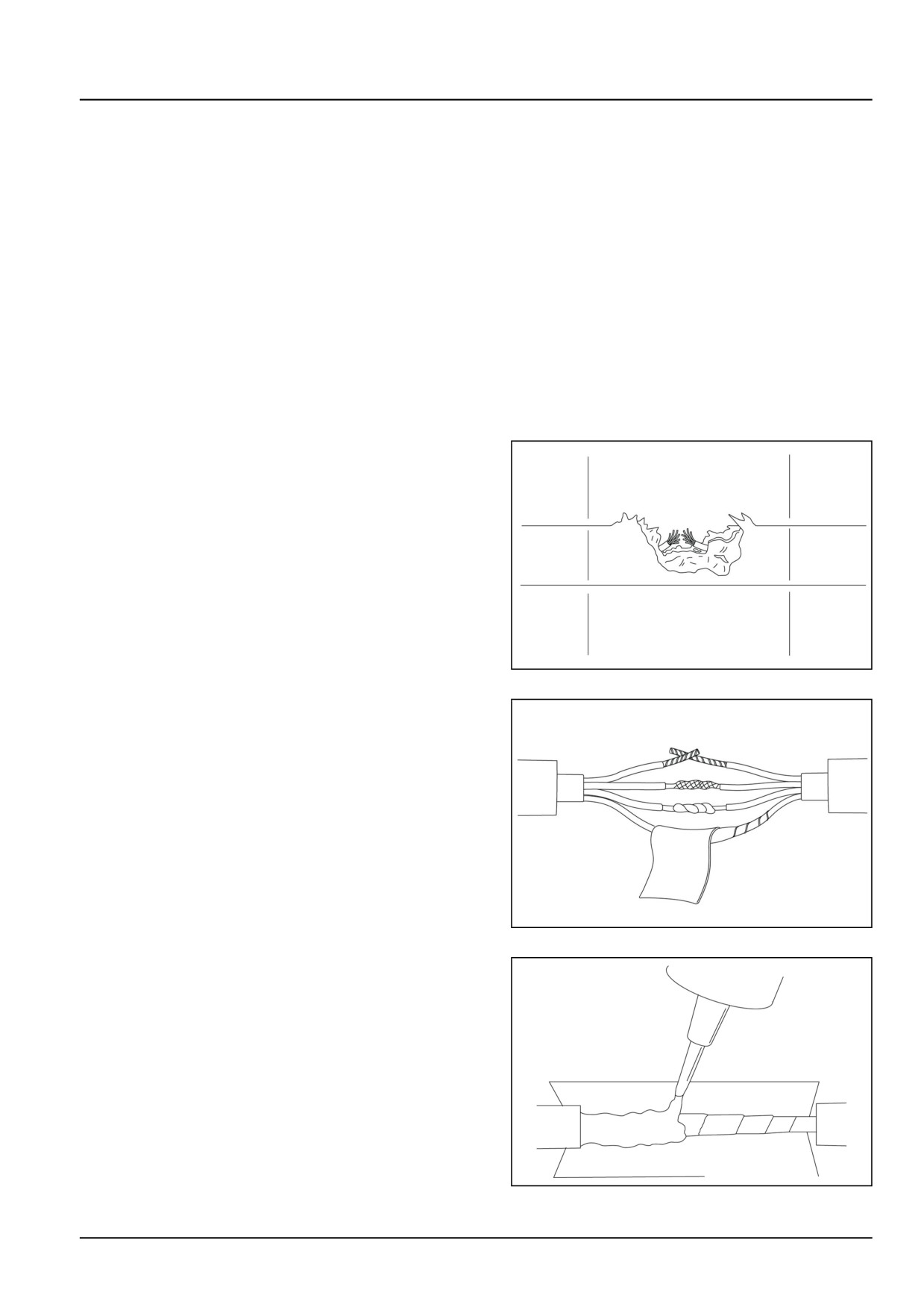
1. Locate damaged portion of cable then cut away outer
protective cover on both sides of the damaged area.
GNIL14TR04711AA
1
2. Peel back the cable from both ends of the damaged
area and carefully cut away the inner cable cover at
the damaged area and strip about 13.00 mm (0.51 in)
of insulation from the wires. Do not cut away any wire
strands.
3. Using a suitable solvent, clean about
50.00 mm
(1.97 in) from each cover end. Clean the grey cable
cover and the individual leads.
4. Twist two bare leads together for each damaged lead,
being careful to match wire colors, then solder the leads
using resin cored solder. Tape each repaired lead with
vinyl insulation tape, figure 2.
GNIL14TR04712AA
2
5. Wind a layer of vinyl insulation tape up to the grey cable
cover at each end of the repair section. Make a paper
trough, figure 3, then apply silicon rubber compound
(non hardening sealant) over the repaired section up
to the cover ends. Sufficient sealant must be used to
fill the ends of the cut away area.
GNIL14TR04713AA
3
55.4 [55.100] / 95
Electrical systems - Harnesses and connectors
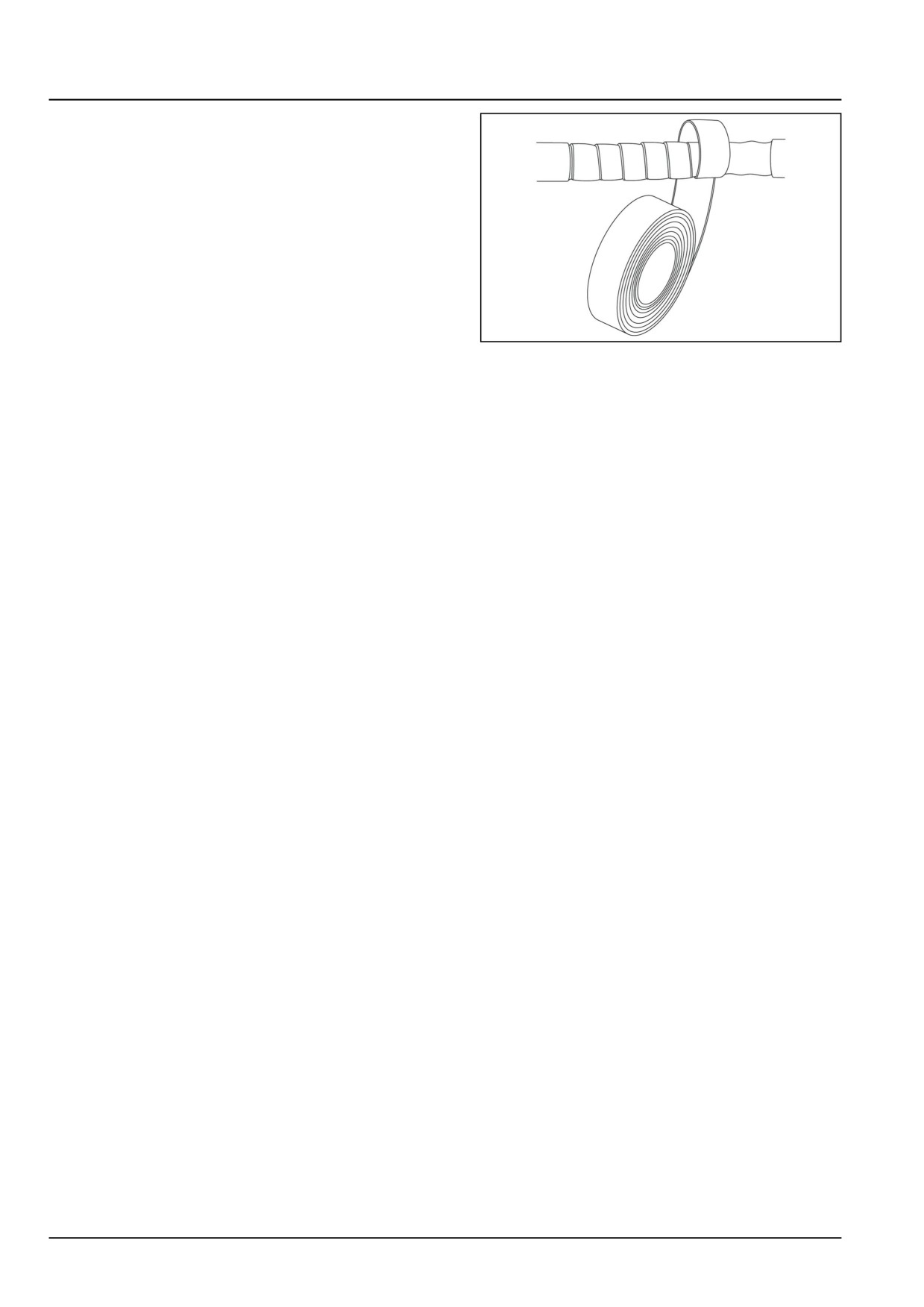
6. Allow the compound to cure, then cover the area with
insulating tape taking the tape well over each end of
the repair. An overlap of at least 50.00 mm (1.97 in) of
tape at each end is necessary, figure 4.
7. Check to ensure the repair is satisfactory and secure
the repaired cable so that repeat damage is avoided.
NOTE: This is a temporary repair only. Ensure the dam-
aged cable is replaced as soon as possible to prevent
ingress of water or chemicals.
GNIL14TR04714AA
4
55.4 [55.100] / 96
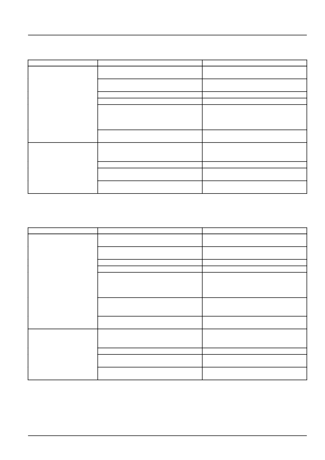
Electrical systems - Harnesses and connectors
Wiring harnesses - Troubleshooting Safety start circuit - Operator
present
Problem
Possible Cause
Correction
Starter motor will not
Insufficient battery charge.
Test battery. Charge, add water, or replace
energize
as necessary.
Blown fusible link.
Inspect and replace fusible link as neces-
sary.
Defective key switch.
Test key switch and replace as necessary.
Defective PTO safety or safety start relay.
Test relays and replace as necessary.
Malfunctioning safety start switch.
Test neutral range, main PTO transmission
clutch, and seat safety start switches for
adjustment, proper operation, and faulty
ground circuits.
Malfunctioning starter motor.
Test starter motor and repair or replace as
necessary.
Starter motor energizes,
Blown fuse ignition, 15 A fuse.
Replace fuse.
but fails to start engine
(lacks exhaust smoke)
Defective operator safety module.
Test module and replace as necessary.
Defective fuel shutoff relay.
Test fuel shutoff relay and replace as nec-
essary.
Malfunctioning fuel shutoff solenoid.
Test fuel shutoff solenoid and replace as
necessary.
Wiring harnesses - Troubleshooting Safety start circuit - Operator
not present
Problem
Possible Cause
Correction
Starter motor will not
Insufficient battery charge.
Test battery. Charge, add water, or replace
energize
as necessary.
Blown fusible link.
Inspect and replace fusible link as neces-
sary.
Defective key switch.
Test key switch and replace as necessary.
Defective PTO safety or safety start relay.
Test relays and replace as necessary.
Malfunctioning safety start switch.
Test neutral range, main PTO transmission
clutch, and seat safety start switches for
adjustment, proper operation, and faulty
ground circuits.
Defective start circuit diode.
Test start circuit diode and replace as nec-
essary. Operator must be out of seat for
test.
Malfunctioning starter motor.
Test starter motor and repair or replace as
necessary.
Starter motor energizes,
Blown fuse ignition, 15 A fuse.
Replace fuse.
but fails to start engine
(lacks exhaust smoke)
Defective operator safety module.
Test module and replace as necessary.
Defective fuel shutoff relay.
Test fuel shutoff relay and replace as nec-
essary.
Malfunctioning fuel shutoff solenoid.
Test fuel shutoff solenoid and replace as
necessary.
55.4 [55.100] / 97
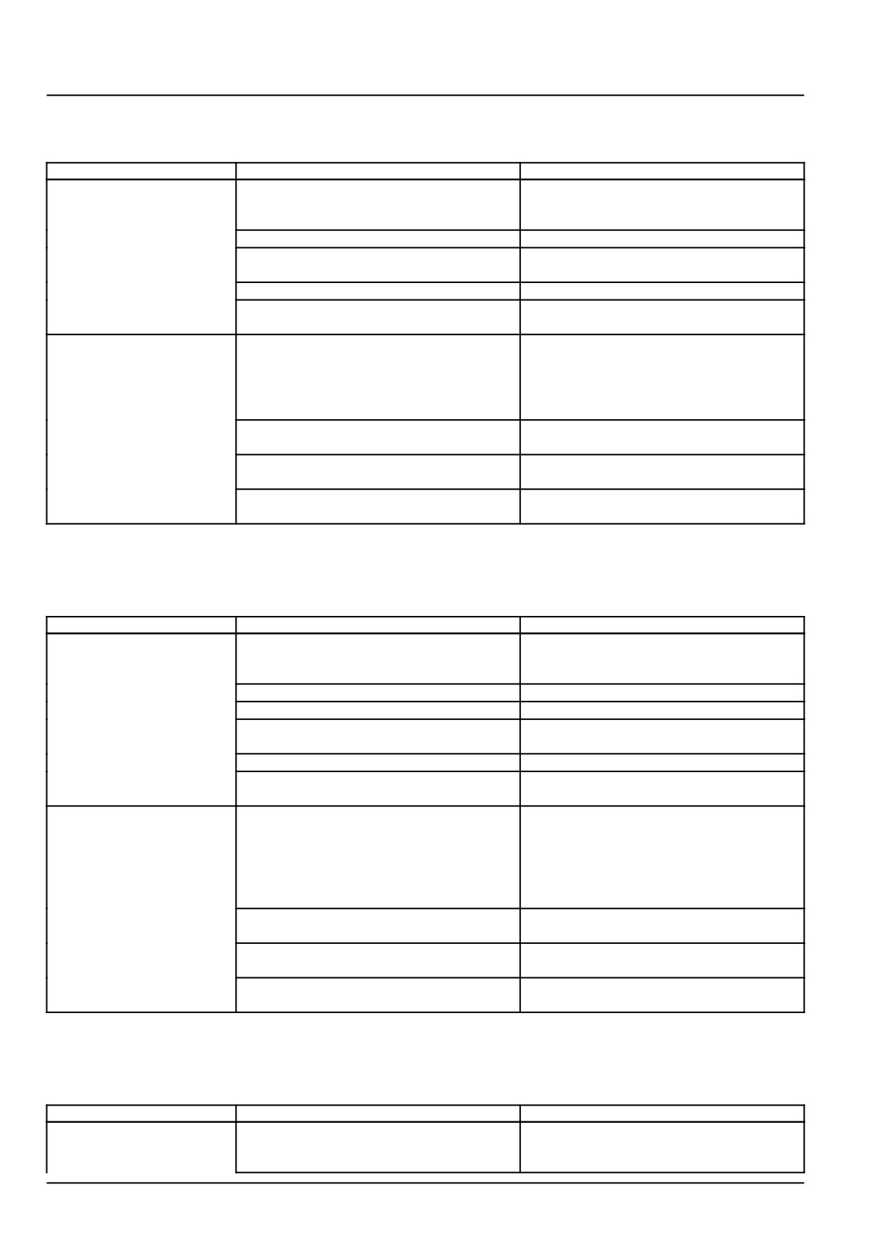
Electrical systems - Harnesses and connectors
Wiring harnesses - Troubleshooting Safe Operation - Operator
Present
Problem
Possible Cause
Correction
Engine does not continue
Defective seat safety switch.
Test seat safety switch and replace as nec-
to run while operator is
essary.
seated
Defective Fuel shutoff relay.
Test relay and replace as necessary.
Malfunctioning fuel shutoff solenoid.
Test fuel shutoff solenoid and replace as
necessary.
Defective operator safety module.
Test module and replace as necessary.
Open wiring in safe operation circuit.
Check for loose connectors, grounds, and
wiring damage.
Engine continues to run
Defective seat safety switch.
Test seat safety switch and replace as nec-
after operator has left
essary.
seat for more than two
seconds and mid PTO and
park brake is not engaged
Defective operator safety module.
Test operator safety module and replace as
necessary.
Malfunctioning fuel shutoff solenoid.
Test fuel shutoff solenoid and replace as
necessary.
Short-circuit in wiring or faulty ground cir-
Check for loose safety switch connectors,
cuit.
grounds, and wiring harness for damage.
Wiring harnesses - Troubleshooting Safe operation - Operator not
present, PTO "OFF"
Problem
Possible Cause
Correction
Engine does not continue
Defective neutral safety switch.
Test neutral safety switch and replace as
to run while operator is
necessary.
seated
Blown 3 A diode.
Check diode, replace if necessary.
Defective Fuel shutoff relay.
Test relay and replace as necessary
Malfunctioning fuel shutoff solenoid.
Test fuel shutoff solenoid and replace as
necessary.
Defective operator safety module.
Test module and replace as necessary.
Open wiring in safe operation circuit.
Check for loose connectors, grounds, and
wiring damage.
Engine continues to
Defective neutral safety switch.
Test neutral safety switch and replace as
run after operator
necessary.
has left seat for more
than two seconds with
transmission range in
gear
Defective operator safety module.
Test operator safety module and replace as
necessary.
Malfunctioning fuel shutoff solenoid.
Test fuel shutoff solenoid and replace as
necessary.
Short-circuit in wiring or faulty ground cir-
Check for loose safety switch connectors,
cuit.
grounds, and wiring harness for damage.
Wiring harnesses - Troubleshooting Safe operation - Operator not
present; PTO “ON”
Problem
Possible Cause
Correction
Engine does not continue
Defective fuel shutoff relay.
Test relay and replace as necessary.
to run while operator is
not seated
55.4 [55.100] / 98
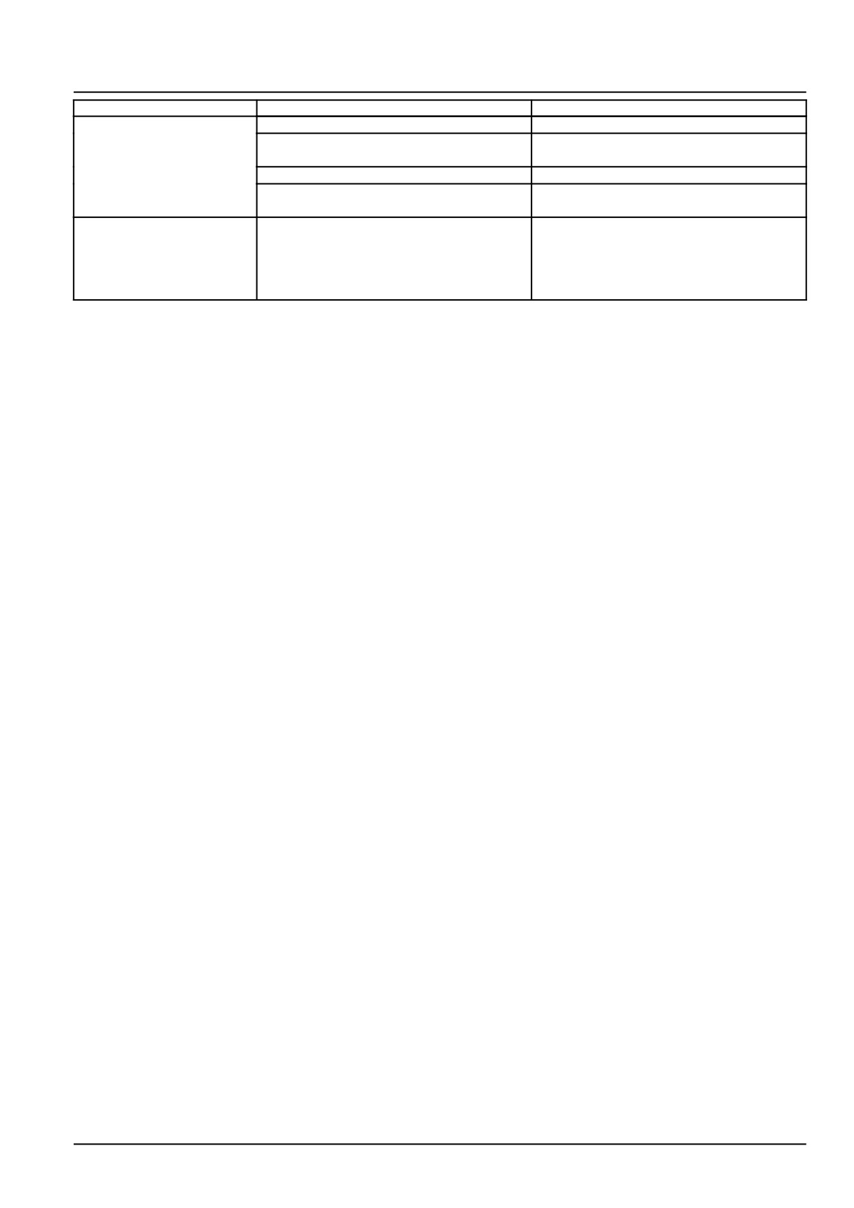
Electrical systems - Harnesses and connectors
Problem
Possible Cause
Correction
Blown 3 A diode.
Check diode, replace if necessary.
Malfunctioning fuel shutoff solenoid.
Test fuel shutoff solenoid and replace as
necessary.
Defective operator safety module.
Test module and replace as necessary.
Open wiring in safe operation circuit.
Check for loose connectors, grounds, and
wiring damage.
Engine does not continue
Defective range neutral switch, PTO
Test components and replace as neces-
to run when operator is
switch, or 3 A diode.
sary.
not in seat, transmission
is in neutral, PTO is on,
and park brake is engaged
55.4 [55.100] / 99
Index
Electrical systems - 55
Harnesses and connectors - 100
Wiring harnesses - Electrical schematic sheet 03 SH03-STARTING/CHARGING SYSTEM
6
Wiring harnesses - Electrical schematic sheet 04 SH04-POWER DISTRIBUTION:GEP RELAY BOX
8
Wiring harnesses - Electrical schematic sheet 05 SH05-GROUNDING SYSTEM
10
Wiring harnesses - Electrical schematic sheet 06 SH06-IGNITION/CONTROL SWITCHES
12
Wiring harnesses - Electrical schematic sheet 07 SH07-INSTRUMENT CLUSTER: ADIC
14
Wiring harnesses - Electrical schematic sheet 08 SH08-ENGINE CONTROL UNIT: ECU
16
Wiring harnesses - Electrical schematic sheet 09 SH09-SAFETY LOGIC
18
Wiring harnesses - Electrical schematic sheet 10 SH10-FRONT HEAD LIGHTS
20
Wiring harnesses - Electrical schematic sheet 11 SH11-REAR LIGHTS
22
Wiring harnesses - Electrical schematic sheet 12 SH12-DIAGONESTIC/TRAILER SOCKET
24
Wiring harnesses - Electrical schematic sheet 01 - Power distribution and glow plugs (engine
schematics)
26
Wiring harnesses - Electrical schematic sheet 02 - Engine Control Unit (ECU) power and after treat-
ment system (engine schematics)
28
Wiring harnesses - Electrical schematic sheet 03 - Engine sensors and fuel injection (engine
schematics)
30
Electrical components - Fuse description
88
Electrical components - Motor description
93
Electrical components - Relay description
91
Electrical components - Switch description
94
Electrical components - Voltage source description
90
Wire connectors - Component diagram 00 - Connectors X-9001 to X-9009
70
Wire connectors - Component diagram 00
33
Wire connectors - Component diagram 01 - Connectors X-9010 to X-9019
75
Wire connectors - Component diagram 01
38
Wire connectors - Component diagram 02 - Connectors X-9020 to X-9029
76
Wire connectors - Component diagram 02
42
Wire connectors - Component diagram 03 - Connectors X-9030 to X-9039
77
Wire connectors - Component diagram 05
46
Wire connectors - Component diagram 10 - Connectors X-9101 to X-9109
81
Wire connectors - Component diagram 10
48
Wire connectors - Component diagram 11 - Connectors X-9110 to X-9119
84
Wire connectors - Component diagram 12 - Connectors X-9120 to X-9129
85
Wire connectors - Component diagram 20
49
55.4 [55.100] / 100
Wire connectors - Component diagram 21
51
Wire connectors - Component diagram 30
54
Wire connectors - Component diagram 40
57
Wire connectors - Component diagram 50
59
Wire connectors - Component diagram 51
62
Wire connectors - Component diagram 52
64
Wire connectors - Component diagram 60
65
Wire connectors - Component diagram 61
66
Wire connectors - Component diagram 70
67
Wire connectors - Component diagram 71
68
Wire connectors - Component diagram 90
69
Wiring harnesses - Electrical schematic sheet 02 SH02-POWER DISTRIBUTION:GEP FUSE BOX
4
Wiring harnesses - Repair
95
Wiring harnesses - Troubleshooting Safe Operation - Operator Present
98
Wiring harnesses - Troubleshooting Safe operation - Operator not present, PTO "OFF"
98
Wiring harnesses - Troubleshooting Safe operation - Operator not present; PTO “ON”
98
Wiring harnesses - Troubleshooting Safety start circuit - Operator not present
97
Wiring harnesses - Troubleshooting Safety start circuit - Operator present
97
55.4 [55.100] / 101
55.4 [55.100] / 102
Electrical systems - 55
Engine starting system - 201
Workmaster™ 50
Workmaster™ 60
Workmaster™ 70
55.5 [55.201] / 1
Contents
Electrical systems - 55
Engine starting system - 201
FUNCTIONAL DATA
Engine starting system
Dynamic description
3
SERVICE
Engine starter
Remove
5
Install
6
DIAGNOSTIC
Engine starter
Troubleshooting
7
55.5 [55.201] / 2
Electrical systems - Engine starting system
Engine starting system - Dynamic description
Description of operation
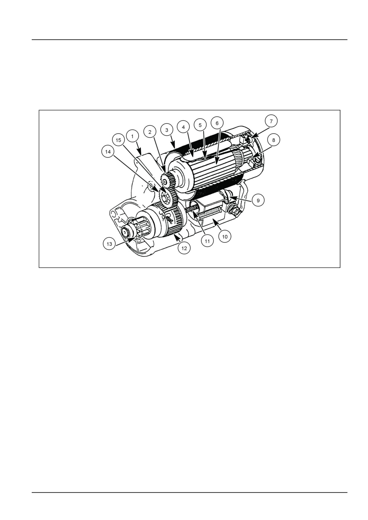
The starting system consists of a starter motor equipped with an electromagnetic starter solenoid, a key switch, a
start relay, several safety switches, and heavy-duty wiring.
Starter components
SEC55CH4PG28
1
(1) Reduction Uni Cover
(9) Plunger
(2) Armature Drive Gear
(10) Solenoid
(3) Motor/Field Coil Housing (Yoke)
(11) Return Spring
(4) Permanent Magnet
(12) Pinion Clutch
(5) Field Coil
(13) Pinion
(6) Armature
(14) Idler Gear
(7) Brush Spring
(15) Idler Gear Roller Bearing
(8) Brush
Starter motor assembly
The starter motor features a high-speed motor that utilizes a gear reduction unit, an overrunning pinion clutch, (12),
and permanent magnets, (4), in a field coil, (5), for magnetic field induction. The reduction unit consists of a small
drive gear, (2), on the motor armature, (6), which drives an idler gear, (14), in the reduction unit. The idler gear is
splined to the gear on the pinion clutch housing, (12). When the starter solenoid, (10), is energized, the solenoid
plunger, (9), pushes the pinion gear, (13), out, engaging with the engine flywheel. The starter motor then is turning
the flywheel, which rotates the engine. The use of the gear reduction unit allows use of the compact, high-speed
motor and provides more torque and power to turn the engine flywheel. The sliding pinion mechanism is enclosed,
resulting in a more durable mechanism.
55.5 [55.201] / 3
Electrical systems - Engine starting system
Starter solenoid
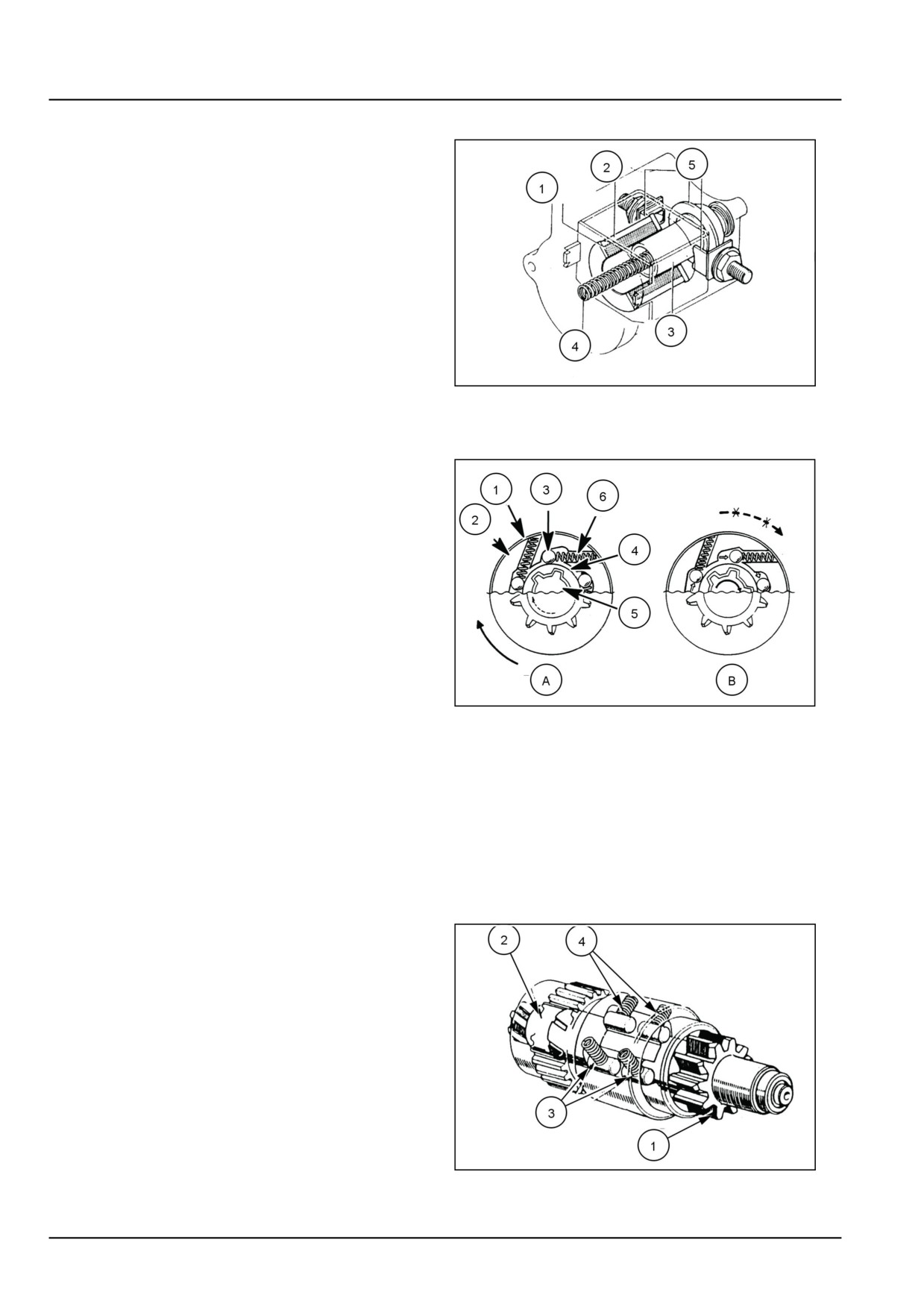
The starter solenoid is an electromagnetic type solenoid
that is located on the bottom of the starter motor assem-
bly. The solenoid contains two coils, a pull-in coil, (1)
and a hold-in coil (2) When the key switch is turned to
the "START" position and the safety start relay is closed
(safety switches closed), current from the battery will en-
ergize the solenoid's two coils. With the coils energized,
the solenoid plunger, (3) pushes a spring (4) which will
then push the pinion gear out to engage the flywheel. At
the same time, a set of contacts (5), on the solenoid be-
come closed, allowing current to flow to the starter motor.
Closing the contacts also supplies current to both ends
of the solenoid pull in coil which makes the coil become
non-energized. The hold-in coil continues to engage the
pinion gear with the flywheel.
SEC55CH4PG29_1
2
Pinion clutch
To prevent the engine from driving the starter motor once
the engine is running, the pinion gear is equipped with an
overrunning clutch. The clutch will disengage the pinion
gear from the rest of the starter components once the en-
gine has been started and the key switch is in the "START"
position. The clutch consists of an outer gear/shell, (1), a
cam with tapered notches, (2), rollers, (3), roller springs,
(4), a splined pinion collar/tube that acts as a clutch hub,
(5), and the pinion shaft, (6). As the starter motor engages
and rotates, the rollers are locked against the pinion collar
with the tension provided by the roller springs. While the
rollers are locked, the clutch assembly is locked, allowing
the pinion gear to rotate the flywheel. When the engine
starts, the flywheel moves faster than the starter motor
and this causes the rollers to become unlocked. With the
SEC55CH4P29_2
3
rollers unlocked, the clutch assembly is unlocked, allow-
A-
Engaged,
B-
Disengaged
ing the pinion gear and shaft to turn independently of the
starter motor.
(1) Clutch Gear
(2) Cam
(3) Roller
(4) Spline Tube - Inner (Pinion Collar)
(5) Pinion Shaft
(6) Roller Spring
The clutch is not serviceable and is replaced as a com-
plete assembly.
Once the engine is started and the key switch is released
from the "START" position, the solenoid's pull in coil be-
comes energized, pulling the solenoid plunger in, which
disengages the pinion from the flywheel.
SEC55CH4P29_3
4
55.5 [55.201] / 4
Electrical systems - Engine starting system
Engine starter - Remove
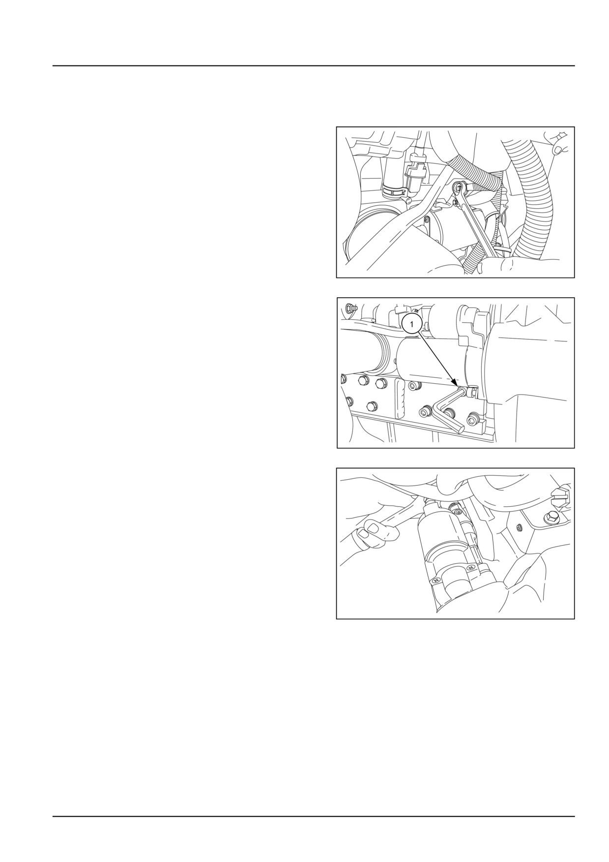
1. Lift the front hood.
Disconnect the battery terminals (Negative first).
2. Disconnect the electrical connection from the starter
motor.
GNIL14TR00713AA
1
3. Remove the set screw (1) on the front axle support.
It interferes while the starter motor mounting bolts are
loosened.
GNIL14TR00736AA
2
4. Loosen the starter motor mounting bolts. Remove the
starter motor.
GNIL14TR00735AA
3
55.5 [55.201] / 5
Electrical systems - Engine starting system
Engine starter - Install
For installation, follow the removal process in reverse
order.
55.5 [55.201] / 6
Electrical systems - Engine starting system
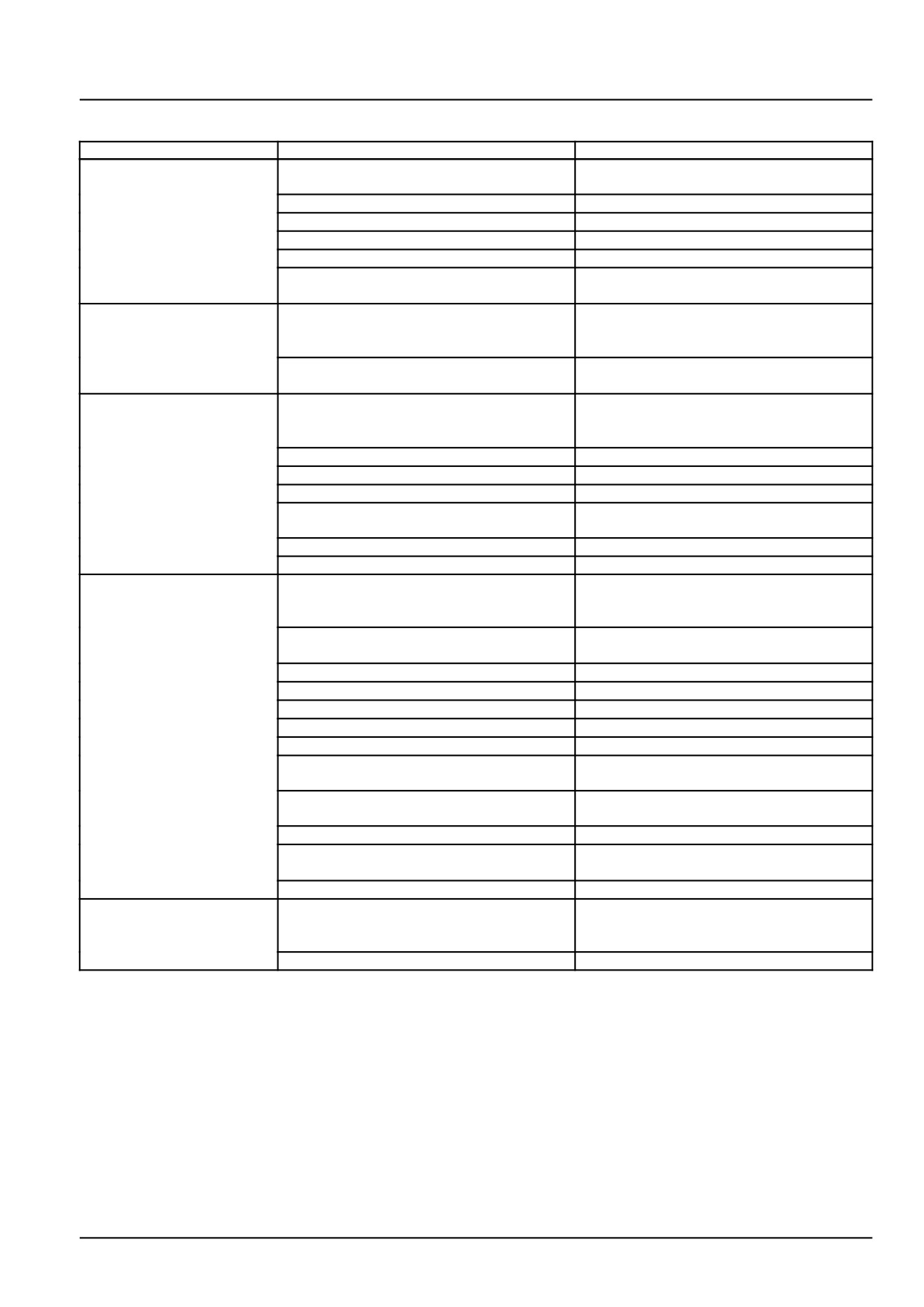
Engine starter - Troubleshooting
Problem
Possible Cause
Correction
Pinion shaft fails to
Wiring: Open circuit battery, and switch ter-
Repair or replace.
advance
minal connections.
Wiring: Open circuit, fuse.
Replace fuse.
Key switch: No contact.
Repair or replace.
Starter motor: Sleeve bearing burnt out.
Repair or replace.
Starter motor: Lever broken.
Replace.
Solenoid: Plunger movement defective or
Repair or replace.
coil open or shorted.
Pinion motor rotates but
Starting motor: Clutch defective.
Replace.
no rotation transmitted to
engine
Starting motor: Orbital gear or planetary
Replace.
gears damaged.
Motor rotates before
Starter motor: Shift lever damaged.
Replace.
pinion meshes with ring
gear
Starter motor: :Shift lever damaged
Replace.
Starter motor: Slip ring defective.
Replace.
Starter motor: Pinion teeth worn.
Replace.
Starter motor: Pinion push out position de-
Adjust.
fective.
Engine: Ring gear worn.
Replace.
Solenoid defective
Replace.
Pinion meshes with ring
Wiring: Line connecting solenoid to battery
Repair or replace.
gear but starting motor
broken or defective ground.
fails to turn
Wiring: Lead wire connecting solenoid to
Repair or replace.
motor tightened improperly.
Starting motor: Ball bearing locked.
Replace.
Starting motor: Brush worn.
Replace.
Starting motor: Improper installation.
Reinstall.
Starting motor: Brush spring defective.
Replace.
Starting motor: Commutator dirty.
Clean.
Starting motor: Armature of field coil defec-
Repair or replace.
tive.
Starting motor: Field coil-to-brush connec-
Replace.
tion defective.
Solenoid: Contact not touching properly.
Replace.
Solenoid: Contact contacting surface
Replace.
roughened.
Battery: In discharge state.
Recharge or replace.
Motor fails to stop after
Key switch: defective.
Replace.
engine starts and key
switch is turned off
Defective solenoid.
Replace.
55.5 [55.201] / 7
Index
Electrical systems - 55
Engine starting system - 201
Engine starter - Install
6
Engine starter - Remove
5
Engine starter - Troubleshooting
7
Engine starting system - Dynamic description
3
55.5 [55.201] / 8
Electrical systems - 55
Alternator - 301
Workmaster™ 50
Workmaster™ 60
Workmaster™ 70
55.6 [55.301] / 1
Contents
Electrical systems - 55
Alternator - 301
DIAGNOSTIC
Alternator
Troubleshooting
3
55.6 [55.301] / 2
Electrical systems - Alternator
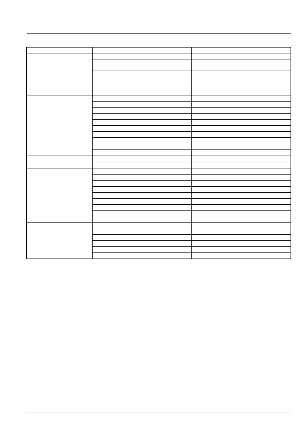
Alternator - Troubleshooting
Problem
Possible Cause
Correction
No charging
Wiring: Loose connection or short circuit.
Repair.
Alternator: Loose connection, no ground,
Repair or replace.
or short circuit.
Alternator: Defective rectifier.
Replace.
Regulator: Defective regulator.
Replace.
Regulator: Loose connection of alternator
Repair or replace.
or regulator.
Insufficient charging
Wiring: Loose connection or short circuit.
Repair.
Alternator: Loose drive belt.
Repair.
Alternator: Short in rotor coil.
Replace.
Alternator: Short in stator coil.
Replace.
Alternator: Defective rectifier.
Replace.
Alternator: Insufficient brush contact.
Repair or replace.
Regulator: Defective regulator.
Replace.
Regulator: Loose connection of alternator
Repair.
and regulator.
Battery: Defective Battery.
Replace.
Overcharge
Battery: Internal short.
Replace.
Regulator: Defective regulator.
Replace.
Unstable Charging Circuit
Wiring: Loose connection or open wire.
Repair or replace.
Alternator: Loose drive belt.
Repair.
Alternator: Short in rotor coil.
Replace.
Alternator: Short in stator coil.
Replace.
Alternator: Broken brush or spring.
Replace.
Alternator: Loose connection.
Repair.
Regulator: Defective Regulator.
Replace.
Regulator: Loose connection at alternator
Repair or replace.
and regulator.
Abnormal Noise from
Alternator: Loose mounting hardware.
Repair.
Alternator
Alternator: Defective bearings.
Repair or replace.
Alternator: Rotor core and stator in contact.
Replace.
Alternator: Defective diode.
Replace.
Alternator: Short in stator coil.
Replace.
55.6 [55.301] / 3
Index
Electrical systems - 55
Alternator - 301
Alternator - Troubleshooting
3
55.6 [55.301] / 4
Electrical systems - 55
Battery - 302
Workmaster™ 50
Workmaster™ 60
Workmaster™ 70
55.7 [55.302] / 1
Contents
Electrical systems - 55
Battery - 302
SERVICE
Battery
Remove
3
Check
4
Install
5
55.7 [55.302] / 2
Electrical systems - Battery
Battery - Remove
WARNING
Improper operation or service of this machine can result in an accident.
Before working on any component(s) of the electrical circuit, put the starter switch key in the off (shut
down) position. When disconnecting batteries, always disconnect the negative (-) cable first. When
reconnecting batteries, always connect the negative (-) cable last.
Failure to comply could result in death or serious injury.
W0264A
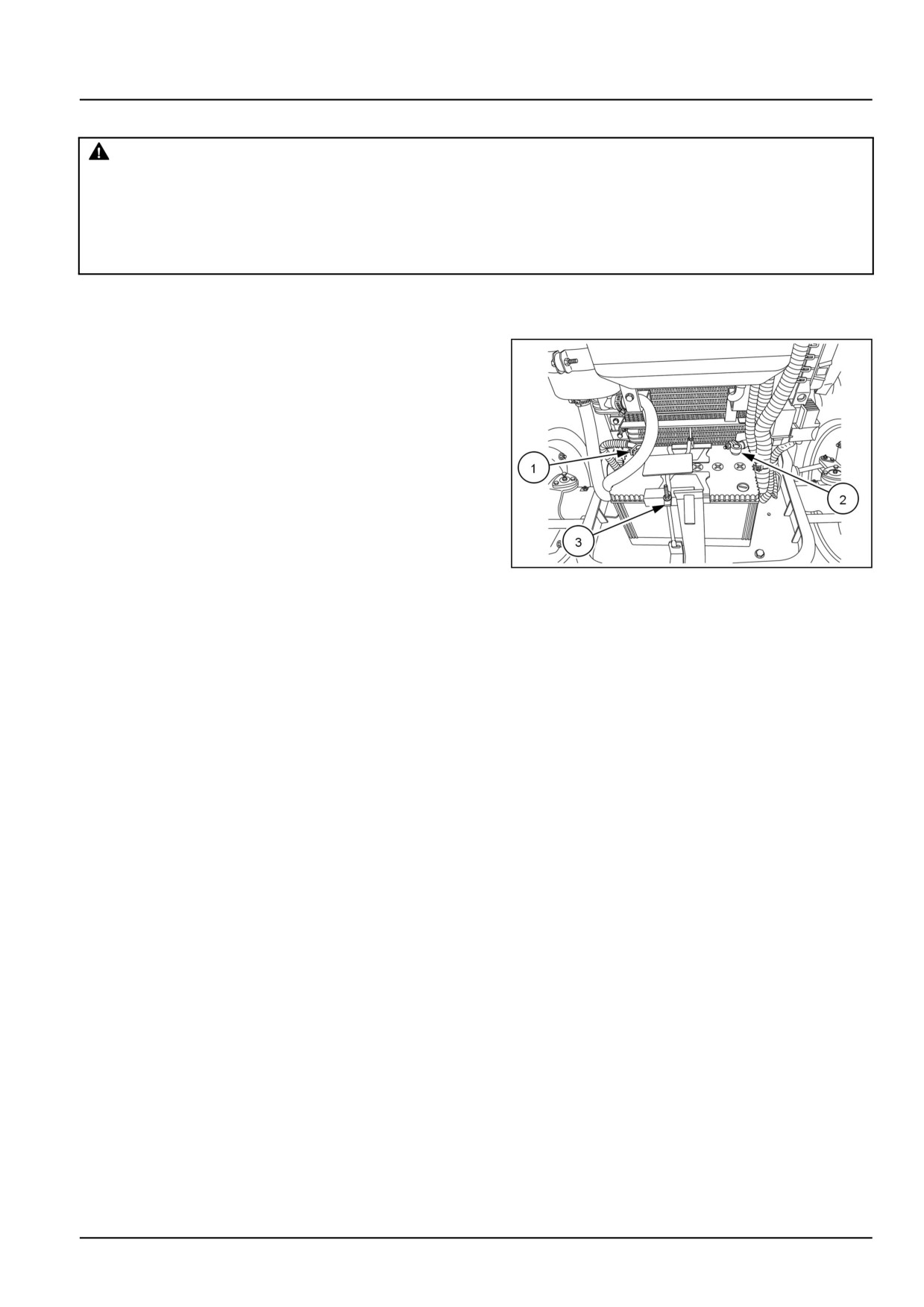
1. Unlatch and raise the hood to gain access to the bat-
tery.
2. Remove the negative (-) cable, (1), from the negative
(-) terminal on the battery.
3. Remove the positive (+) cable, (2), from the positive (+)
terminal on the battery.
4. Remove the nut, washer and J-bolt, (3), which secures
the battery to the tractor frame.
5. Remove the battery from the tractor.
GNIL14TR00784AA
1
55.7 [55.302] / 3
Electrical systems - Battery
Battery - Check
DANGER
Hazardous chemicals!
Battery electrolyte contains sulfuric acid. Contact with skin and eyes could result in severe irritation
and burns. Always wear splash-proof goggles and protective clothing (gloves and aprons). Wash
hands after handling.
Failure to comply will result in death or serious injury.
D0105A
WARNING
Explosive gas!
Batteries emit explosive hydrogen gas and other fumes while charging. Ventilate the charging area.
Keep the battery away from sparks, open flames, and other ignition sources. Never charge a frozen
battery.
Failure to comply could result in death or serious injury.
W0005A
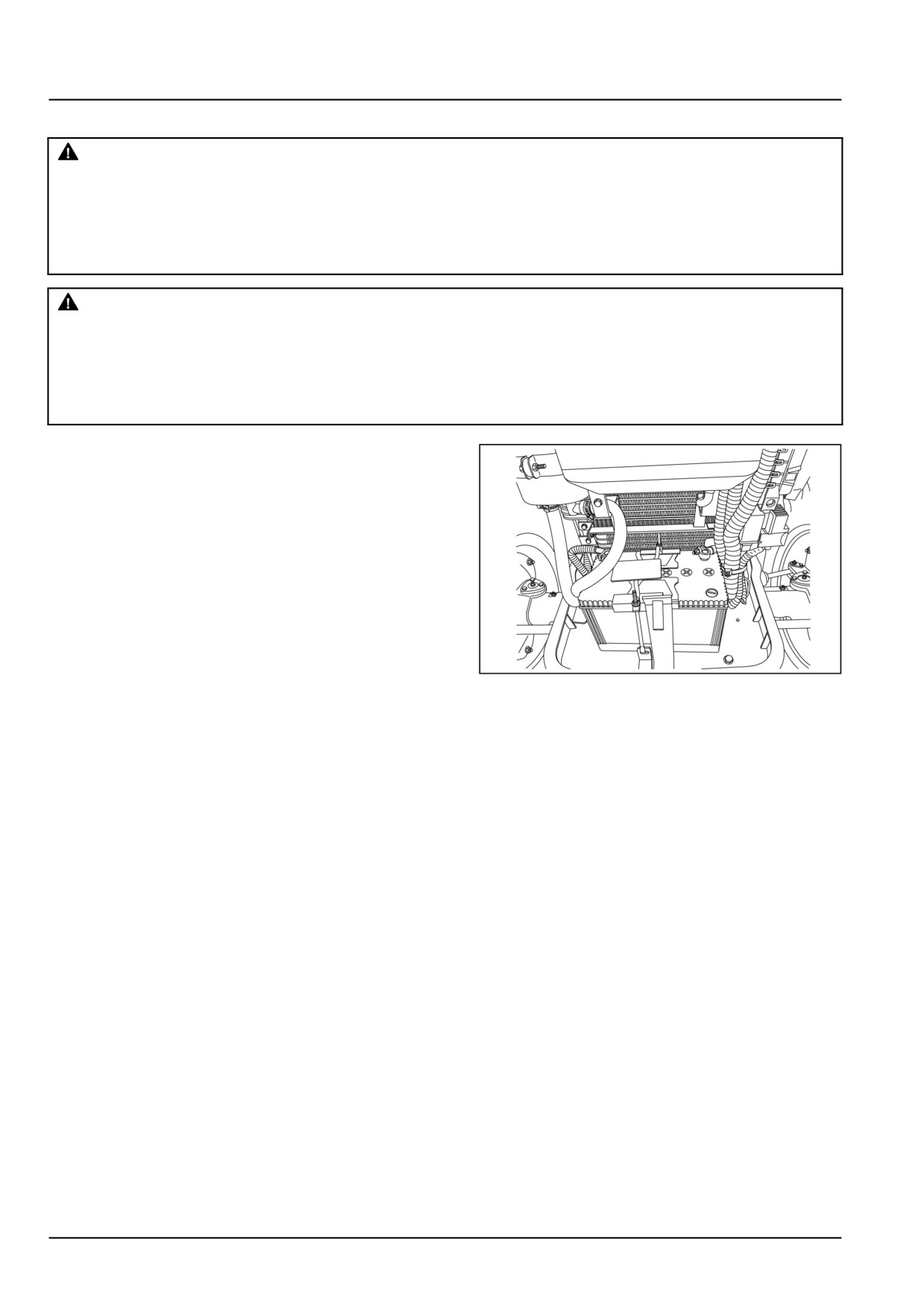
1. The battery is located in front of the radiator.
The battery electrolyte level should be between the
minimum and maximum lines provided on battery con-
tainer.
If necessary, top off with distilled or de-mineralized wa-
ter until the level is correct. Do not overfill. Never use
tap water or water from rain barrel or other source.
To prevent the formation of corrosion, the terminals
should be cleaned and smeared with petroleum jelly
only, no grease should be applied.
NOTE: Battery size - BCI group - 47 (CCA 600--850).
GNIL14TR00784AA
1
55.7 [55.302] / 4
Electrical systems - Battery
Battery - Install
1. Check the battery for cleanliness, especially around the
terminals. Clean the area where the battery mounts
to the tractor frame to prevent debris from piercing the
body of the battery.
2. Check the vent caps for proper installation and tight-
ness.
3. Ensure that no leakage occurs from the battery.
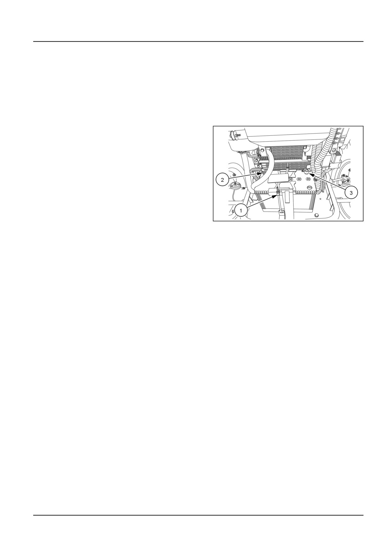
4. Install the battery squarely into position before securing
with strap, and J-bolt, (1).
5. Connect the negative (-) terminal, (2), then the positive
(+) terminal, (3).
NOTE: Coat the battery terminal clamps with petroleum
jelly or equivalent. Do not use conventional lubricants as
electrolyte corrosion may occur.
6. Check battery terminal connections for correct polarity
and tightness. Do not overtighten. Install dust covers
over terminals, (where installed).
GNIL14TR00784AA
1
55.7 [55.302] / 5
Index
Electrical systems - 55
Battery - 302
Battery - Check
4
Battery - Install
5
Battery - Remove
3
55.7 [55.302] / 6