New Holland Tractor Workmaster 50 / Workmaster 60 / Workmaster 70 / Tier 4B (final). SERVICE MANUAL - page 14
Wheels - Front wheels
Front wheels - Adjust
Tread adjustment
1.
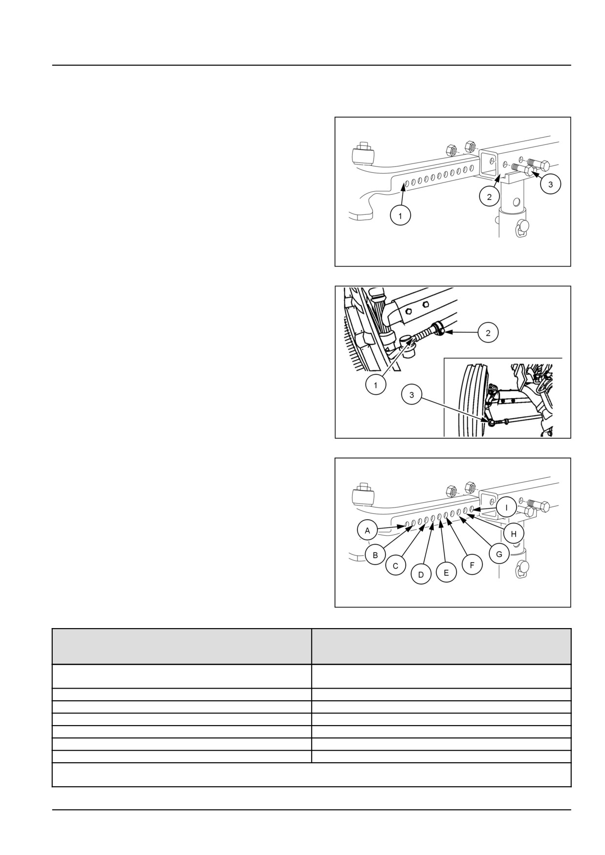
The front axle consists of a hollow center beam (1) with
a telescopic section (2) at each end. Seven holes at
50 mm (1.97 in) intervals are provided in the telescopic
sections for adjustment purposes. Adjustment of the
front wheel track width is done by extending both ends
of the axle equally.
To extend the axle, apply the hand brake and place
blocks at the front and rear of the rear wheels. Jack
up the front axle and place on axle stands. Remove
the securing bolts, (3), securing the left-hand telescopic
section to the center beam.
Repeat the same for the right-hand side of the axle.
GNIL14TR00500AA
1
2.
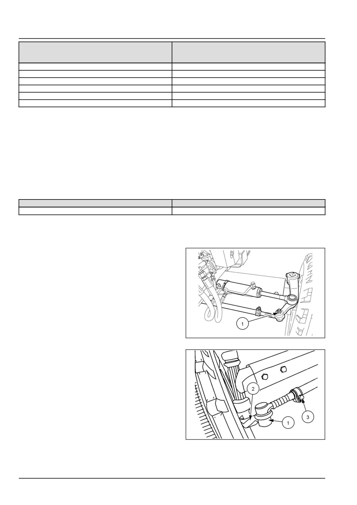
The tie rod is adjustable and consists of a central, hol-
low tube with a solid extendible section at each end.
The left-hand end of the tie rod has a number of notches
(1) at 50 mm (1.97 in) intervals. A locating bolt (2)
passes through a clamp and one of the notches in the
solid section and locks the tie rod assembly at the de-
sired length. Additionally, the right-hand end of the tie
rod is threaded (3) to provide fine adjustment of toe-in.
Remove the locating bolt (2) from the left-hand end of
the tie rod. This will permit the tie rod to extend or
retract freely.
76099305N
2
3.
Reset both axle telescopic sections. Passing the secur-
ing bolts through the center beam and telescopic sec-
tions, as indicated in 3 and table below:
GNIL14TR00500AA
3
Securing
2WD
Bolt
Locations
2WD
7.50 - 16
Dished In
AC
1424 mm
BD
1524 mm
CE
1624 mm
DF
1724 mm
EG
1824 mm
FH
1924 mm
2WD
Dished Out
44.1 [44.511] / 5
Wheels - Front wheels
Securing
2WD
Bolt
Locations
AC
1472 mm
BD
1572 mm
CE
1672 mm
DF
1772 mm
EG
1872 mm
FH
1972 mm
4. Tighten the nuts on the axle extension securing bolts to
118 N·m (87 lb ft).
With both front wheels parallel, install the locating bolt
(2) in the nearest aligning notch in the tie rod. Tighten
the nut on the locating bolt to 24.5 N·m (18 lb ft).
NOTE: The tread settings shown are approximate. The
front wheel discs are off-set, relative to the center line of
the rim. The tread settings in the table are with the dished
side of the wheel nearest the axle hub. If the front wheels
are reversed on the hubs the tread settings shown in the
table will be increased by approximately 25 mm (0.98 in).
Tractor model
Front wheel bolt torque
320.0 N·m (236.0 lb ft)
NOTE: Re-check all torque settings after 50 h of operation.
Tie rod
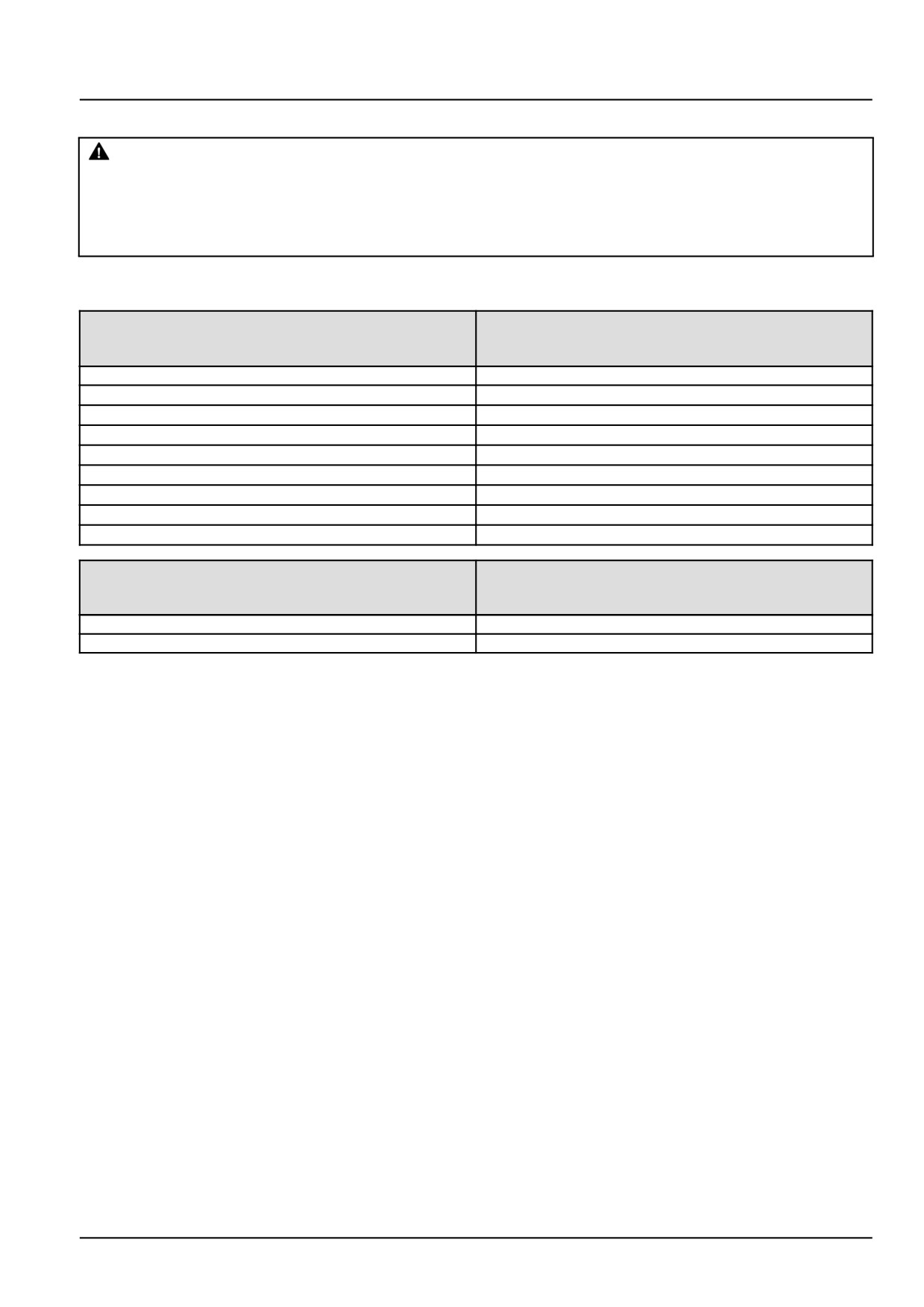
5. The tie rod located behind the axle must be disengaged
to permit adjustment of the axle. The tie rod is tele-
scopic and consists of a central hollow tube with a solid
extendible section at each end. Remove the locating
bolt (1) from both ends of the tie rod. The position
for the setting of the steering cylinder will also change
respectively. Reset the left and right axle telescopic
sections, passing the securing bolts through the center
beam and telescopic sections, as indicated in 3, see
chart.
86090130N
4
6. Remove the nut (1) at the right end of the tie rod. With-
draw the tie rod from arm (2). Loosen the bolt (3) and
rotate the threaded end to shorten or lengthen the tie
rod assembly until the toe-in is correct. Torque all bolts
or nuts securely to correct values.
20108792
5
44.1 [44.511] / 6
Wheels - Front wheels
Front wheels - Adjust
WARNING
Roll-over hazard!
Never operate the machine with a loose wheel rim or disc. Always tighten nuts and/or bolts to the
specified torque value and at the recommended intervals.
Failure to comply could result in death or serious injury.
W0346B
Tread setting
4WD
4WD
Front
Tread
Axle
Setting
9.5 —24
(A)
NA
(B)
NA
(C)
NA
(D)(Standard)
1558.0 mm (61.3 in)
(E)
1522.0 mm (59.9 in)
(F)
1630.0 mm (64.2 in)
(G)
1650.0 mm (65.0 in)
(H)
1758.0 mm (69.2 in)
4WD
Front
Axle
R4 12.5/80-18
Front
1532 mm
44.1 [44.511] / 7
Wheels - Front wheels
1. Front wheel bolt torque: 192.0 N·m (141.6 lb ft)
76096164N-85X23
1
44.1 [44.511] / 8
Index
Wheels - 44
Front wheels - 511
Front wheels - Adjust
5
Front wheels - Adjust
7
Front wheels - Test - 2WD
3
Front wheels - Toe in adjust - 2WD
4
44.1 [44.511] / 9
Wheels - 44
Rear wheels - 520
Workmaster™ 50
Workmaster™ 60
Workmaster™ 70
44.2 [44.520] / 1
Contents
Wheels - 44
Rear wheels - 520
SERVICE
Rear wheel
Adjust
3
44.2 [44.520] / 2
Wheels - Rear wheels
Rear wheel - Adjust
Tread adjustment
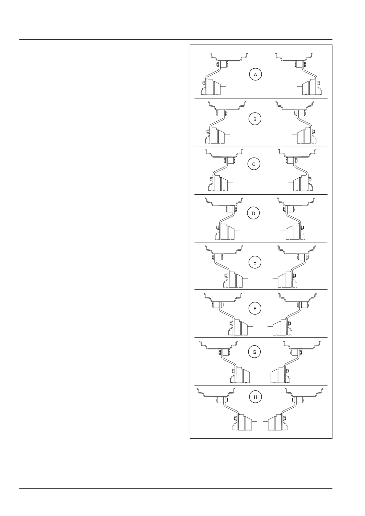
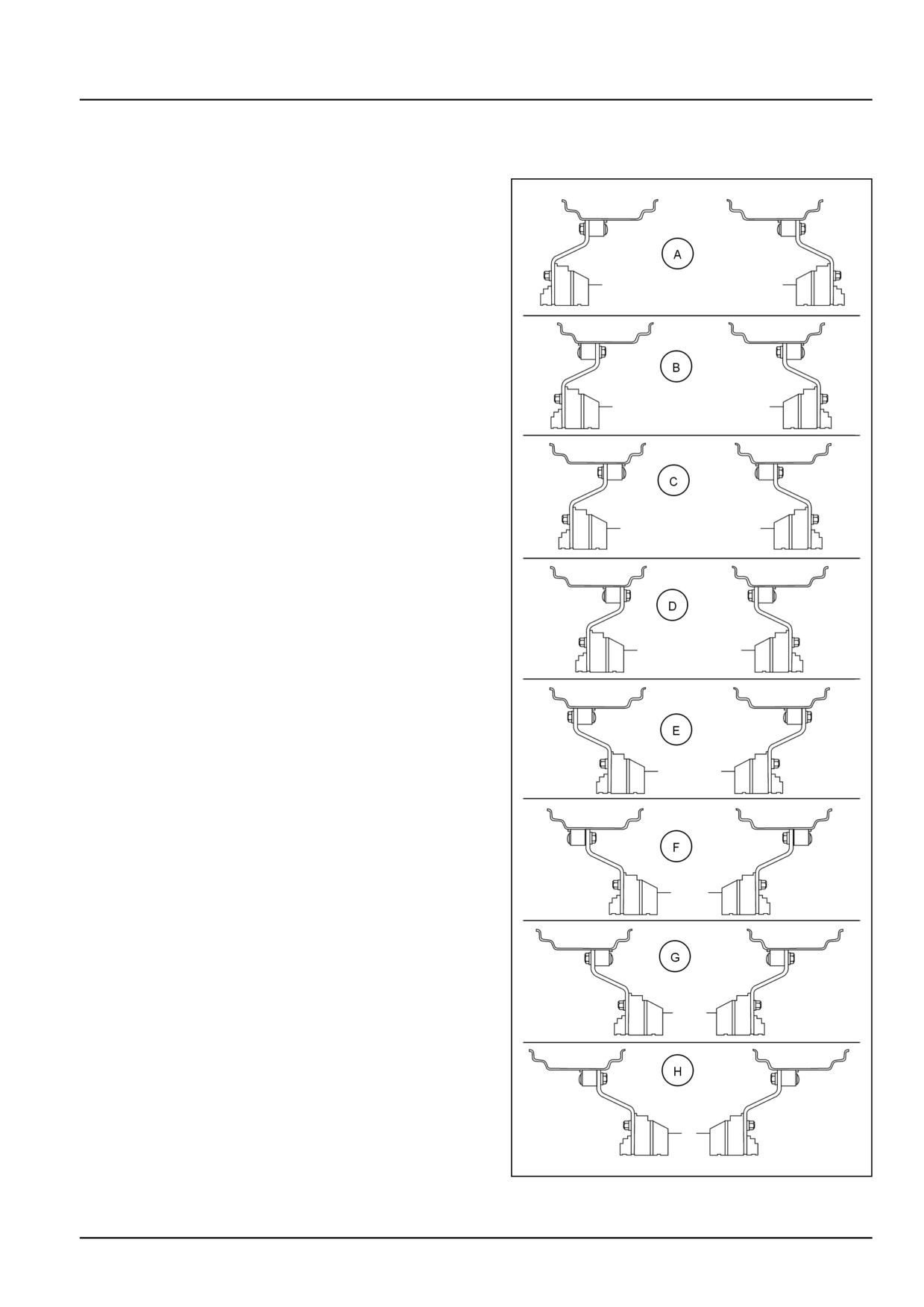
1. Rear wheel track adjustment is done by changing
the wheel rim relative to the center disc, the rim and/or
the disc relative to the axle hub or by interchanging the
rear wheels.
The drawings shown in the table illustrate the wheel
rim and disc positions viewed from rear of the tractor
relative to the hub at various track width settings. Track
width (the distance between the center of the tires) are
nominal and may vary by as much as 13 mm (0.5 in).
2. When installing or adjusting a wheel, torque the bolts
to the following values. Recheck after driving the tractor
for 1 hour and 8 hours operation, and thereafter at the
50 hour intervals:
NOTICE: When interchanging left and right wheel assem-
blies, ensure the “V” of the tire tread remains pointing in the
direction of forward travel of tractor for better grip.
With certain options and/or tire sizes, narrower track set-
tings may not be possible due to minimal clearance be-
tween tires and fenders or equipment.
76096164N-85X23
1
44.2 [44.520] / 3

Wheels - Rear wheels
Rear disc to hub bolts
192 N·m (142 lb ft)
Rear disc to rim nuts
239 N·m (176 lb ft)
Rear Axle
2WD
2WD & 4WD
4WD
Configuration
13.6 R 28
14.9 R 28
R4 18.4X24
(A)
N/A
N/A
N/A
(B)
N/A
N/A
1438.0 mm (56.6 in)
(C)
N/A
N/A
N/A
(D)
1336.0 mm (52.6 in)
1336.0 mm (52.6 in)
N/A
(E)
1420.0 mm (56 in)
1420.0 mm (56 in)
N/A
(F)
1534.0 mm (60.4 in)
1534.0 mm (60.4 in)
N/A
(G)
1623.0 mm (64 in)
1623.0 mm (64 in)
N/A
(H)
1737.0 mm (68.4 in)
1737.0 mm (68.4 in)
N/A
44.2 [44.520] / 4
Index
Wheels - 44
Rear wheels - 520
Rear wheel - Adjust
3
44.2 [44.520] / 5
CNH Industrial America New Holland Site 100 Brubaker Avenue New Holland, Pennsylvania United States
17557
SERVICE - Technical Publications & Tools
PRINTED IN U.S.A.
All rights reserved. No part of the text or illustrations of this publication may be reproduced.
NEW HOLLAND policy is one of continuous improvement and the right to change prices, specification or equipment
at any time without notices is reserved.
All data given in this publication is subject to production variations. Dimensions and weight are approximate only and
the illustrations do not necessarily show products in standard condition. For exact information about any particular
product, please consult your NEW HOLLAND Dealer.
EN
SERVICE MANUAL
Electrical systems
Workmaster™ 50
Workmaster™ 60
Workmaster™ 70
55
Contents
Electrical systems - 55
[55.000] Electrical system
55.1
[55.024] Transmission control system
55.2
[55.048] Rear Power Take-Off (PTO) control system
55.3
[55.100] Harnesses and connectors
55.4
[55.201] Engine starting system
55.5
[55.301] Alternator
55.6
[55.302] Battery
55.7
[55.404] External lighting
55.8
[55.405] External lighting switches and relays
55.9
[55.408] Warning indicators, alarms, and instruments
55.10
[55.512] Cab controls
55.11
[55.DTC] FAULT CODES
55.12
55
Electrical systems - 55
Electrical system - 000
Workmaster™ 50
Workmaster™ 60
Workmaster™ 70
55.1 [55.000] / 1
Contents
Electrical systems - 55
Electrical system - 000
TECHNICAL DATA
Electrical system
General specification
3
FUNCTIONAL DATA
Electrical system
Overview
4
DIAGNOSTIC
Electrical system
Troubleshooting
5
55.1 [55.000] / 2
Electrical systems - Electrical system
Electrical system - General specification
Main system protection
Mega Fuse 125 A
Number of fuses for protection
6
Alternator
75 A
Battery type
12 V
Negative ground
BCI group 47
CCA 600-850
Cold-start aid
Yes
Starter motor - type
Solenoid operated
Starter kw (hp) rating
2.0 kW (2.7 Hp)
Bulb rating and type
Head light
12 V 55/65 W
Turn signal
12 V 21 W
Tail light
12 V 21 W / No. 1157
Parking lamp
12 V 5 W
Work lamp
12 V 50 W
Enhanced turn lamps (red)
12 V 21 W
55.1 [55.000] / 3
Electrical systems - Electrical system
Electrical system - Overview
The electrical system of the tractor consists of various
wiring harnesses, lights, switches, battery, alternator,
starter and instrument cluster.
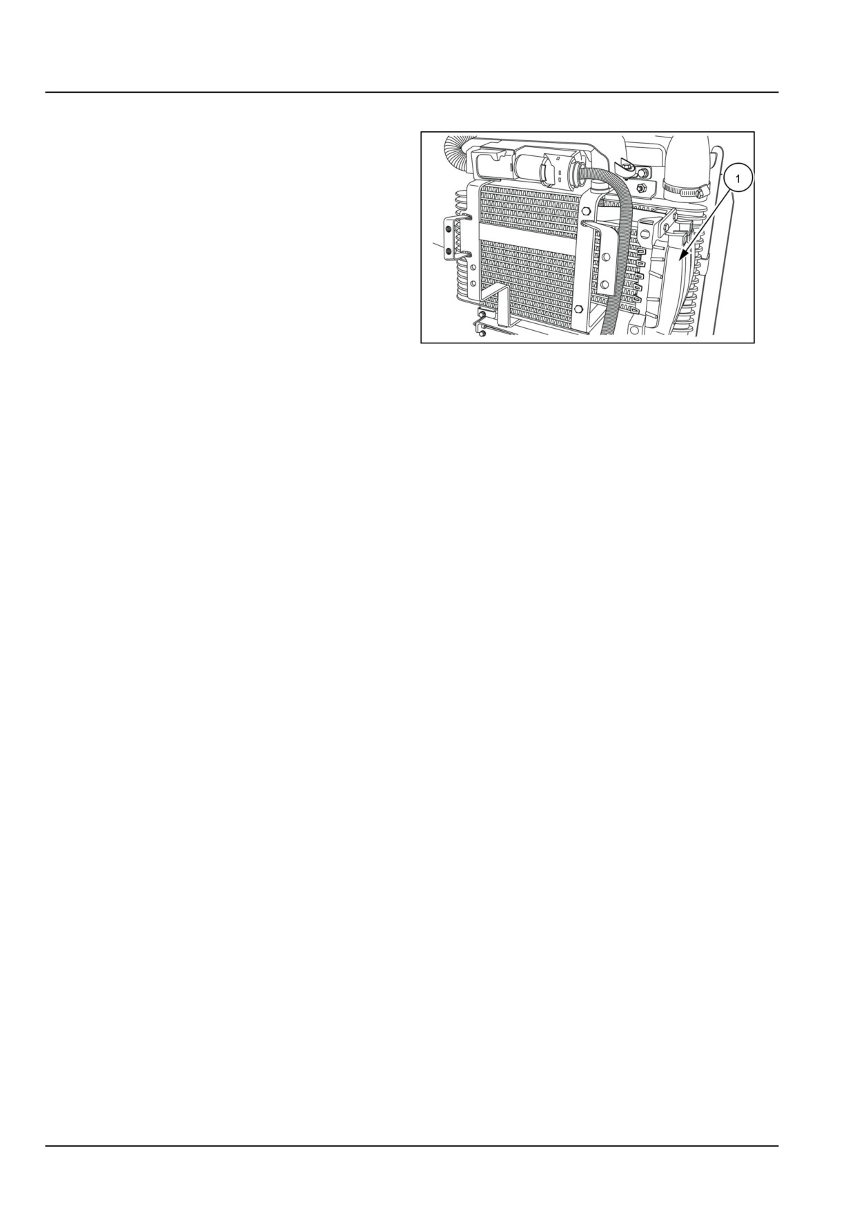
Fuses (1) protect electrical circuits with thin pieces of
wire, which heat up and melt when too much current flows
through them. This opens circuit and protects the wiring
from burning. This can occur in the event of a ‘short
circuit’, or by connecting equipment which demands a
current greater than the circuit, designed to carry. The
fuse is specially designed and in the event of failure, a
new fuse of the same rating should be fitted.
NOTICE: The fuse should never be repaired or replaced
by a fuse of a higher rating.
GNIL14TR00762AA
1
If the fuse repeatedly ‘blows’ the cause must be investi-
gated and repaired.
55.1 [55.000] / 4
Electrical systems - Electrical system
Electrical system - Troubleshooting
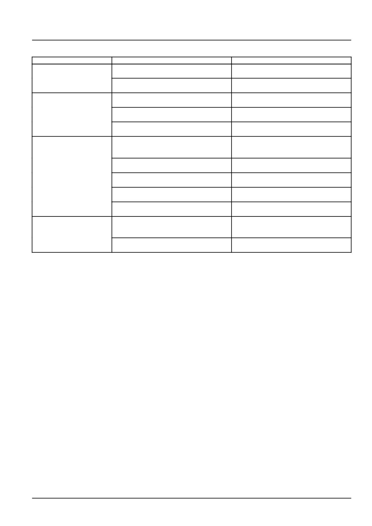
Problem
Possible Cause
Correction
Charge light remains
Faulty alternator component.
Test alternator and repair a necessary.
illuminated
Short circuit to ground between alternator
Check wiring and repair as necessary.
and warning lamp.
Charge light does not
Blown fuse panel, 15 A instrument panel
Inspect 15 A fuse and replace as neces-
illuminate
fuse.
sary.
Faulty charge indicator bulb.
Inspect indicator bulb and replace as nec-
essary.
Open charge light circuit.
Inspect connections, grounds, and wiring
for charge circuit and repair as necessary.
Insufficient or no battery
Battery charge less than 75%.
Test battery. Charge, add water, or replace
charge, hard starting, or
as necessary.
dim indicator light
Fan belt slipping.
Check fan belt tension, adjust as neces-
sary.
Loose wiring connections.
Check wiring connections for charge cir-
cuit, repair as necessary.
Continuity fault in external wiring.
Check wiring harness and repair as neces-
sary.
Blown fuse panel, 15 A alternator excita-
Inspect 15 A fuse and replace as neces-
tion fuse.
sary.
Battery failure, frequent
Overcharge condition.
Check alternator voltage output and repair
burnout of lamps and
as necessary.
fuses
Ground circuit for alternator short-circuited.
Check alternator wiring and connections
and repair as necessary.
55.1 [55.000] / 5
Index
Electrical systems - 55
Electrical system - 000
Electrical system - General specification
3
Electrical system - Overview
4
Electrical system - Troubleshooting
5
55.1 [55.000] / 6
Electrical systems - 55
Transmission control system - 024
Workmaster™ 50
Workmaster™ 60
Workmaster™ 70
55.2 [55.024] / 1
Contents
Electrical systems - 55
Transmission control system - 024
SERVICE
Transmission control system
Ground speed control - Test Transmission range safety switch (*)
3
(*) See content for specific models
55.2 [55.024] / 2
Electrical systems - Transmission control system
Ground speed control - Test Transmission range safety switch
Workmaster™ 50
NA
Workmaster™ 60
NA
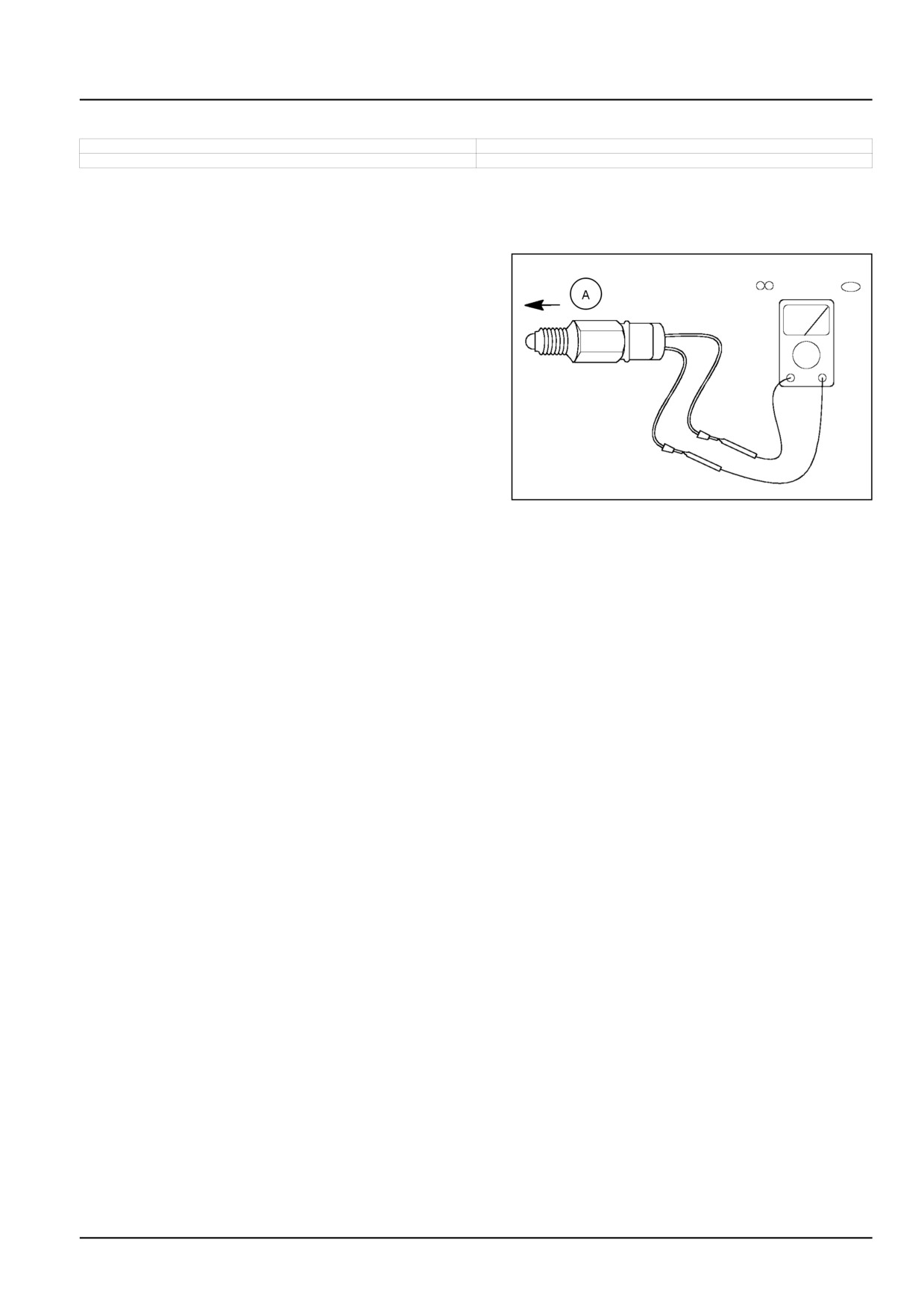
NOTE: Use an ohmmeter to test the transmission range safety switch for electrical continuity.
Extended position
1. With the transmission range safety switch plunger
in the extended position "A", there will be electrical
continuity across the terminal leads.
1. If continuity does not exist while the switch is in the
"Extended " position, the switch is defective and needs
replaced.
30002201
1
Retracted position (not shown)
1. With the switch plunger in retracted position, conti-
nuity will not exist between the terminal leads.
2. If continuity exits while the switch is in the "Retracted"
position, the switch is defective and needs replaced.
55.2 [55.024] / 3
Index
Electrical systems - 55
Transmission control system - 024
Ground speed control - Test Transmission range safety switch (*)
3
(*) See content for specific models
55.2 [55.024] / 4
Electrical systems - 55
Rear Power Take-Off (PTO) control system - 048
Workmaster™ 50
Workmaster™ 60
Workmaster™ 70
55.3 [55.048] / 1
Contents
Electrical systems - 55
Rear Power Take-Off (PTO) control system - 048
FUNCTIONAL DATA
Power Take-Off (PTO) speed sensor
Static description PTO Safety switch
3
SERVICE
Power Take-Off (PTO) speed sensor
Remove
4
Install
5
55.3 [55.048] / 2
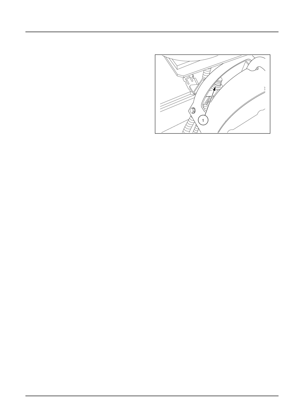
Electrical systems - Rear Power Take-Off (PTO) control system
Power Take-Off (PTO) speed sensor - Static description PTO Safety
switch
The PTO safety switch, (1), is a double pole, single throw-
style switch located on the PTO control lever quadrant.
The switch has a rubber booted push button actuator and
is activated by the PTO clutch lever. When the PTO clutch
lever is in the "OFF" position, the switch button is "OUT"
when the PTO clutch is engaged the switch button is in
the "IN" position.
86072157
1
55.3 [55.048] / 3
Electrical systems - Rear Power Take-Off (PTO) control system
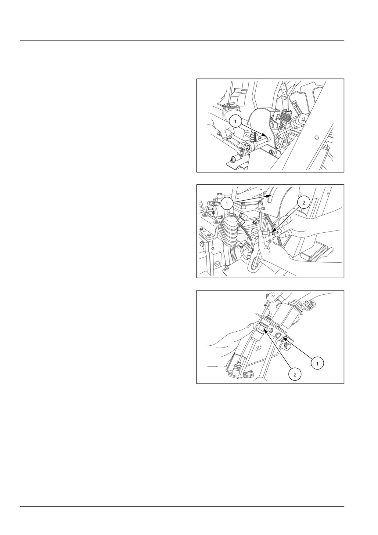
Power Take-Off (PTO) speed sensor - Remove
1. Remove the fender from left side of the tractor. See
Fenders and guards - Remove (90.116).
2. Loosen the bolts (1).
GNIL14TR00840AA
1
3. Lift the plate (1) access the wire connector.
4. Disconnect the wiring (2).
GNIL14TR00838AA
2
5. Loosen the bolts (1) and remove the sensor assem-
bly.
6. Loosen the nut (2) and remove the PTO sensor.
GNIL14TR00839AA
3
55.3 [55.048] / 4
Electrical systems - Rear Power Take-Off (PTO) control system
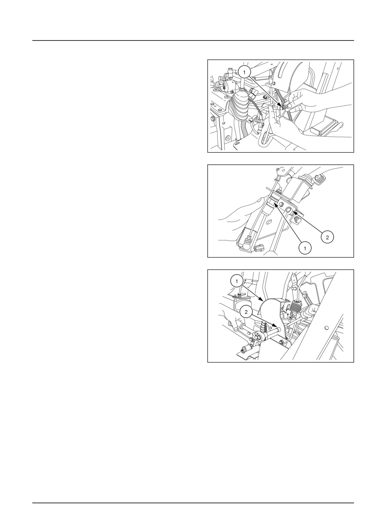
Power Take-Off (PTO) speed sensor - Install
1. Connect the wiring (1).
GNIL14TR00838AA
1
2. Fit the PTO sensor and tighten the nut (1).
3. Tighten the bolts (2).
GNIL14TR00839AA
2
4. Install the plate (1). Tighten the bolts (2).
GNIL14TR00840AA
3
55.3 [55.048] / 5
Index
Electrical systems - 55
Rear Power Take-Off (PTO) control system - 048
Power Take-Off (PTO) speed sensor - Install
5
Power Take-Off (PTO) speed sensor - Remove
4
Power Take-Off (PTO) speed sensor - Static description PTO Safety switch
3
55.3 [55.048] / 6
Electrical systems - 55
Harnesses and connectors - 100
Workmaster™ 50
Workmaster™ 60
Workmaster™ 70
55.4 [55.100] / 1
Contents
Electrical systems - 55
Harnesses and connectors - 100
FUNCTIONAL DATA
Wiring harnesses
Electrical schematic sheet 02 SH02-POWER DISTRIBUTION:GEP FUSE BOX
4
Electrical schematic sheet 03 SH03-STARTING/CHARGING SYSTEM
6
Electrical schematic sheet 04 SH04-POWER DISTRIBUTION:GEP RELAY BOX
8
Electrical schematic sheet 05 SH05-GROUNDING SYSTEM
10
Electrical schematic sheet 06 SH06-IGNITION/CONTROL SWITCHES
12
Electrical schematic sheet 07 SH07-INSTRUMENT CLUSTER: ADIC
14
Electrical schematic sheet 08 SH08-ENGINE CONTROL UNIT: ECU
16
Electrical schematic sheet 09 SH09-SAFETY LOGIC
18
Electrical schematic sheet 10 SH10-FRONT HEAD LIGHTS
20
Electrical schematic sheet 11 SH11-REAR LIGHTS
22
Electrical schematic sheet 12 SH12-DIAGONESTIC/TRAILER SOCKET
24
Electrical schematic sheet 01 - Power distribution and glow plugs (engine schematics)
26
Electrical schematic sheet 02 - Engine Control Unit (ECU) power and after treatment system (engine
schematics)
28
Electrical schematic sheet 03 - Engine sensors and fuel injection (engine schematics)
30
Wire connectors
Component diagram 00
33
Component diagram 01
38
Component diagram 02
42
Component diagram 05
46
Component diagram 10
48
Component diagram 20
49
Component diagram 21
51
Component diagram 30
54
Component diagram 40
57
Component diagram 50
59
Component diagram 51
62
Component diagram 52
64
Component diagram 60
65
Component diagram 61
66
Component diagram 70
67
Component diagram 71
68
55.4 [55.100] / 2
Component diagram 90
69
Component diagram 00 - Connectors X-9001 to X-9009
70
Component diagram 01 - Connectors X-9010 to X-9019
75
Component diagram 02 - Connectors X-9020 to X-9029
76
Component diagram 03 - Connectors X-9030 to X-9039
77
Component diagram 10 - Connectors X-9101 to X-9109
81
Component diagram 11 - Connectors X-9110 to X-9119
84
Component diagram 12 - Connectors X-9120 to X-9129
85
Electrical components
Fuse description
88
Voltage source description
90
Relay description
91
Motor description
93
Switch description
94
SERVICE
Wiring harnesses
Repair
95
DIAGNOSTIC
Wiring harnesses
Troubleshooting Safety start circuit - Operator present
97
Troubleshooting Safety start circuit - Operator not present
97
Troubleshooting Safe Operation - Operator Present
98
Troubleshooting Safe operation - Operator not present, PTO "OFF"
98
Troubleshooting Safe operation - Operator not present; PTO “ON”
98
55.4 [55.100] / 3
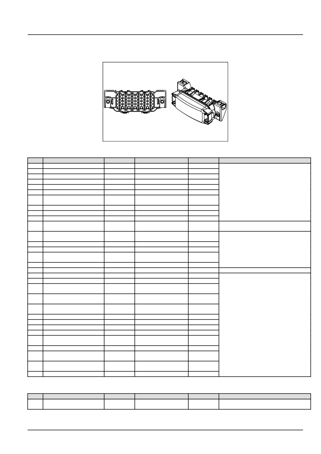
Electrical systems - Harnesses and connectors
Wire connectors - Component diagram 00
X-001 - (84380518) (Female)
84380518
1
84380518
Pin
From
Wire
Description
Color-Size
Frame
1
SP-019-P-X
009R
009R
BK - 0.75
SHEET 04
2
SP-013-P-X
055
055
RD - 3.0
3
SP-019-P-X
009L
009L
BK - 0.5
4
SP-069-P-X
069B
069B
RD - 1.5
9
SP-056-P-X
056
056
OR/GN - 3.0
10
SP-022-P-X
022B
022B
RD/GN - 0.75
12
X-406B pin 10 TO MAIN
059
059
GN/YE - 0.5
HARNESS
13
SP-019-P-X
009P
009P
BK - 0.75
14
SP-013-P-X
055A
055A
RD - 3.0
15
SP-017-P-X
009E
009E
BK - 0.75
16
X-009 pin 85 CRANKING
050
050
BL - 0.75
SHEET 02
RELAY
21
X-404B pin 22 MAIN-ENGINE
076
076
OR/BL - 1.5
SHEET 04
INTERCONNECT
22
SP-022-P-X
022A
022A
RD/GN - 0.75
23
SP-017-P-X
009F
009F
BK - 0.75
24
X-406B pin 7 TO MAIN
053
053
YE - 0.75
HARNESS
25
SP-019-P-X
009S
009S
BK - 0.5
26
SP-025-P-X
031A
031A
RD/BL - 1.5
SHEET 02
27
SP-017-P-X
009K
009K
BK - 0.5
SHEET 04
28
SP-097-P-X
095
095
GY - 0.75
33
X-216B pin 5 HEADLAMP
032
WORK LAMP
OR - 1.5
INTERCONNECT
34
X-406B pin 3 TO MAIN
091
091
PRP - 0.5
HARNESS
35
X-404B pin 4 MAIN-ENGINE
108
108
VT - 0.75
INTERCONNECT
36
SP-096-P-X
096B
096B
GY - 0.5
37
SP-019-P-X
009M
009M
BK - 0.5
38
SP-069-P-X
069A
069A
RD - 1.5
39
SP-017-P-X
009W
009W
BK - 0.75
40
X-201 (Female) pin 62 ECU
046
046
BL - 0.75
VEHICLE
43
SP-017-P-X
009V
009V
BK - 0.75
45
X-216B pin 1 HEADLAMP
100
100
GN/YE - 1.5
INTERCONNECT
46
X-406B pin 11 TO MAIN
074
074
BL/YE - 0.5
HARNESS
48
F-002-P-38 GEP - FUSE BOX
115
115
OR - 0.75
X-001A - [ G-001] (Male)
Pin
From
Wire
Description
Color-Size
Frame
PIN1
X-004A (Male) pin PIN1
001
BATTERY CABLE
RD - 40.0
SHEET 03
POSITIVE
55.4 [55.100] / 33
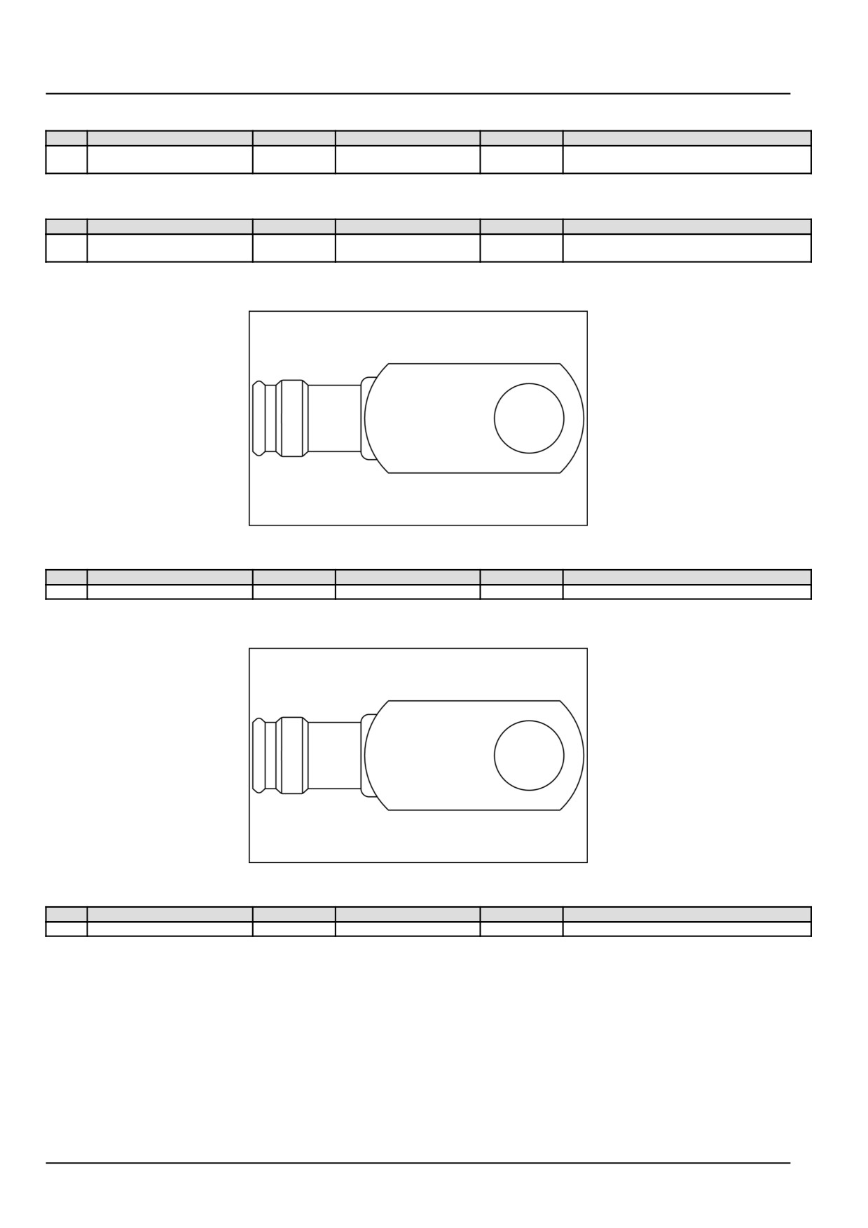
Electrical systems - Harnesses and connectors
X-001B - [ G-001] (Male)
Pin
From
Wire
Description
Color-Size
Frame
PIN1
X-002A (Male) pin PIN1
002
BATTERY CABLE
BK - 40.0
SHEET 03
GROUND TERMINAL
GROUND
X-002A - GROUND TERMINAL (Male)
Pin
From
Wire
Description
Color-Size
Frame
PIN1
X-001B pin PIN1
002
BATTERY CABLE
BK - 40.0
SHEET 03
GROUND
X-002B - FENDER GROUND (84153309) (Male)
84153309
2
84153309
Pin
From
Wire
Description
Color-Size
Frame
1
SP-010-P-X
010
FENDER GROUND
BK - 6.0
SHEET 05
X-002C - MAIN HARNESS GND (84153309) (Male)
84153309
3
84153309
Pin
From
Wire
Description
Color-Size
Frame
1
SP-005-P-X
005
MAIN HARNESS GND
BK - 6.0
SHEET 05
55.4 [55.100] / 34
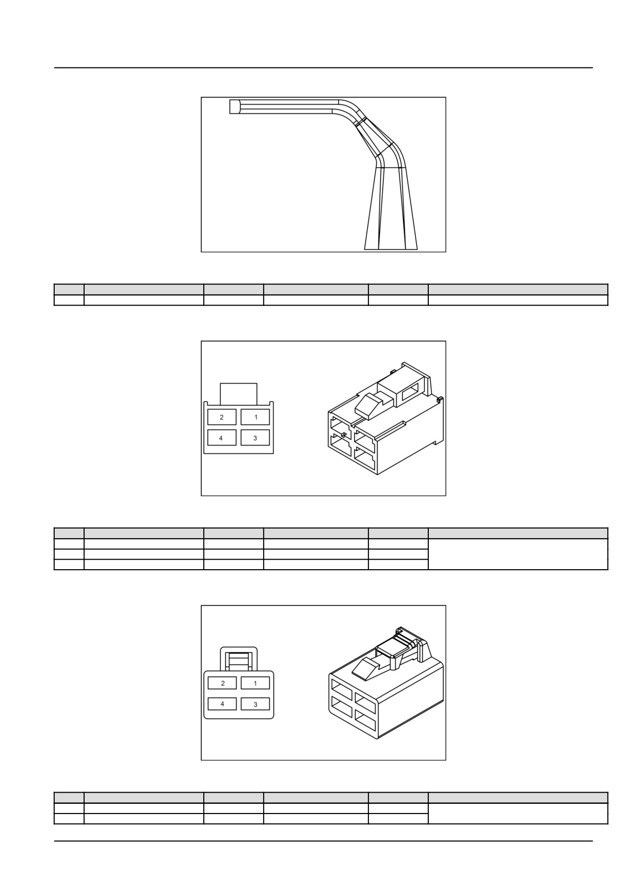
Electrical systems - Harnesses and connectors
X-002D - ECU/ENGINE GROUND (84179566) (Male)
84179566
4
84179566
Pin
From
Wire
Description
Color-Size
Frame
1
SP-009-P-X
009
ECU/ENGINE GROUND
BK - 6.0
SHEET 05
X-003 - IGNITION SWITCH [ S-001] (84479009) (Female)
84479009
5
84479009
Pin
From
Wire
Description
Color-Size
Frame
2
SP-106-P-X
021A
021A
RD - 3.0
SHEET 06
3
X-406A-P-2
065
065
YE - 0.75
4
SP-101-P-X
089A
089A
RD/GN - 2.5
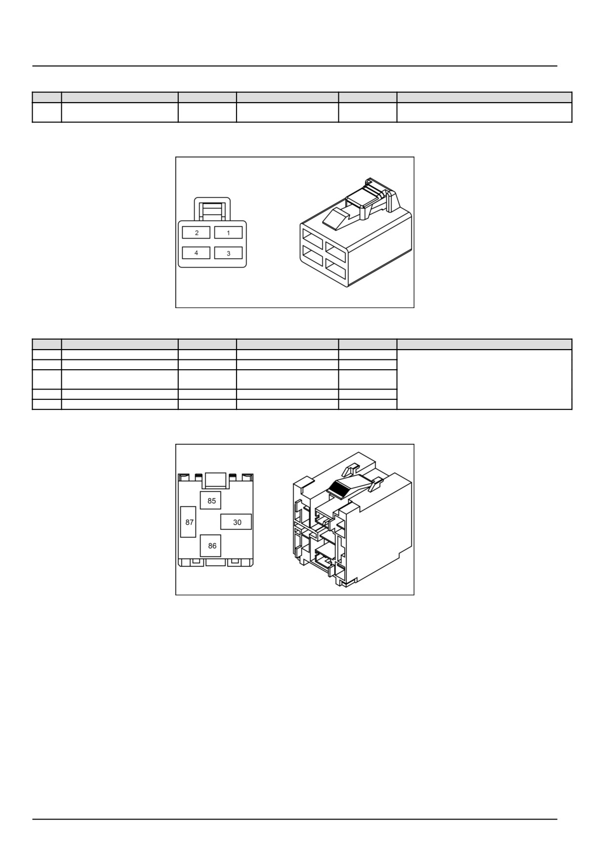
X-004 - DIODE (84179574) (Female)
84179574
6
84179574
Pin
From
Wire
Description
Color-Size
Frame
1
SP-096-P-X
096A
096A
GY - 0.75
SHEET 04
2
SP-097-P-X
095A
095A
GY - 0.75
55.4 [55.100] / 35
Electrical systems - Harnesses and connectors
X-004A - [ M-001] (Male)
Pin
From
Wire
Description
Color-Size
Frame
PIN1
X-001A (Male) pin PIN1
001
BATTERY CABLE
RD - 40.0
SHEET 03
POSITIVE
X-005 - LIGHT SWITCH (84179574) (Female)
84179574
7
84179574
Pin
From
Wire
Description
Color-Size
Frame
1
SP-060-P-X
060
060
BL/YE - 0.75
SHEET 06
2
SP-029-P-X
029C
029C
GN/OR - 1.5
2
HORN/LIGHT/TURN
WIRE235
WIRE235
SWITCH-P-PWR1
3
X-406A-P-10
073
073
GN/YE - 0.75
4
SP-058-P-X
058
058
BL/BK - 0.75
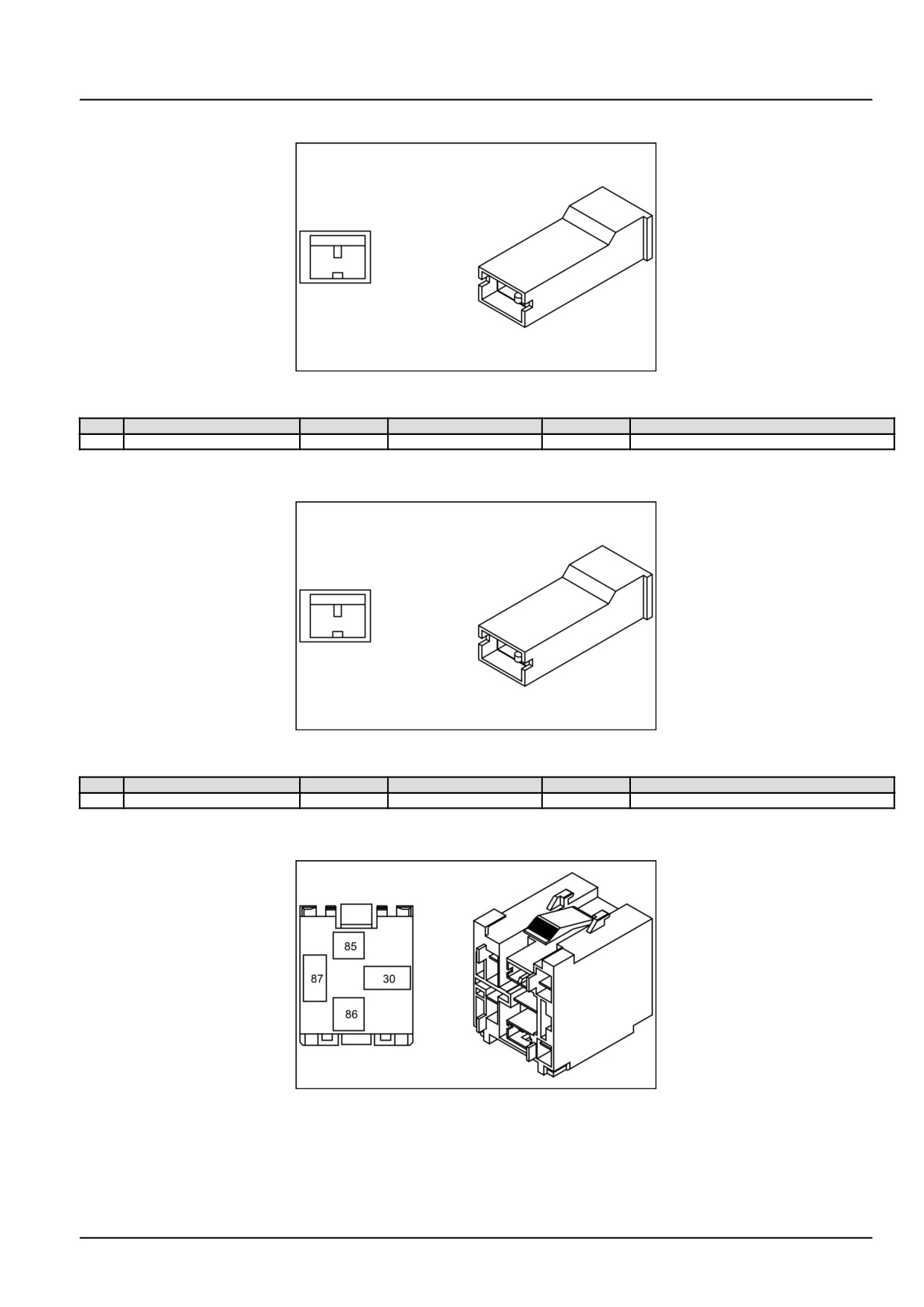
X-006 - ECU RELAY (47781083) (Male)
47781083
8
47781083
55.4 [55.100] / 36
Electrical systems - Harnesses and connectors
X-007 - HORN SWITCH CN1 (87581782) (Female)
87581782
9
87581782
Pin
From
Wire
Description
Color-Size
Frame
1
SP-029-P-X
029B
029B
GN/OR - 0.75
SHEET 06
X-008 - HORN SWITCH CN2 (87581782) (Female)
87581782
10
87581782
Pin
From
Wire
Description
Color-Size
Frame
1
X-406A-P-12
071
071
YE/BL - 0.75
SHEET 06
X-009 - CRANKING RELAY (47781083) (Male)
47781083
11
47781083
55.4 [55.100] / 37
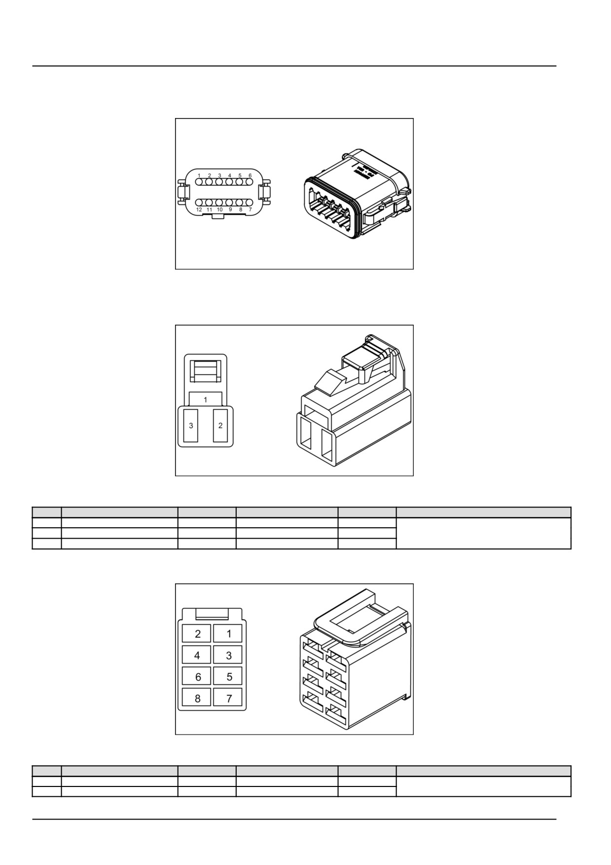
Electrical systems - Harnesses and connectors
Wire connectors - Component diagram 01
X-011 - TURN FLASHER (47781082) (Male)
47781082
1
47781082
X-012 - TURN SWITCH (84179572) (Female)
84179572
2
84179572
Pin
From
Wire
Description
Color-Size
Frame
1
F-003-P-1 MINI FUSER
030
TURN/STOP LAMP
LG - 0.75
SHEET 06
2
X-011 pin 8 TURN FLASHER
061
061
LG/BL - 0.75
3
X-011 pin 7 TURN FLASHER
062
062
LG/WH - 0.75
X-013 - WORK LAMP (84179576) (Female)
84179576
3
84179576
Pin
From
Wire
Description
Color-Size
Frame
4
SP-029-P-X
029D
029D
GN/OR - 1.0
SHEET 06
6
SP-090-P-X
090A
090A
VT - 0.75
55.4 [55.100] / 38
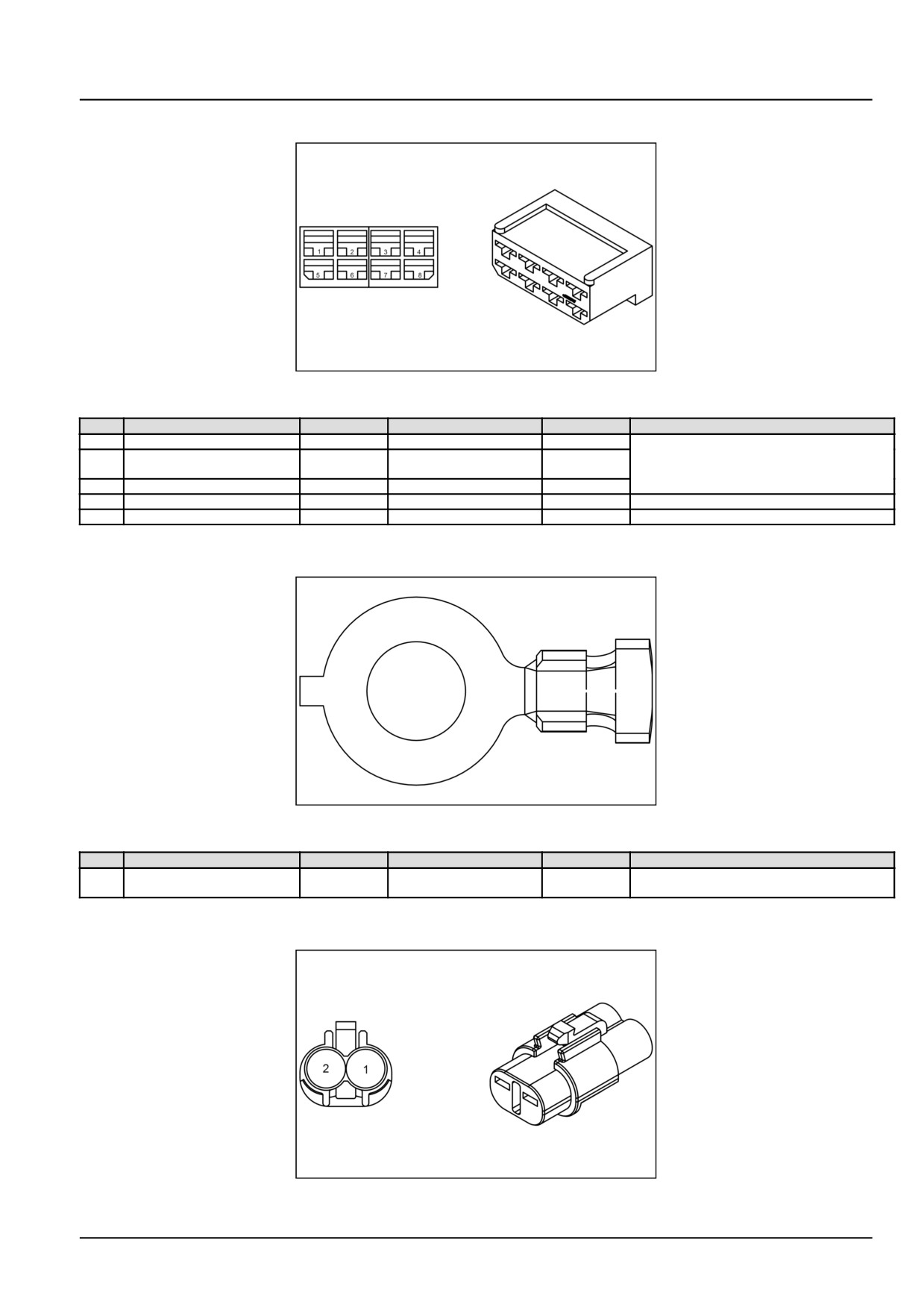
Electrical systems - Harnesses and connectors
X-014 - SAFETY BUZZER (87700098) (Female)
87700098
4
87700098
Pin
From
Wire
Description
Color-Size
Frame
1
SP-025-P-X
031B
031B
RD/BL - 0.75
SHEET 09
2
X-406B pin 8 TO MAIN
034
034
BL - 0.75
HARNESS
3
SP-159-P-X
159B
159B
PK/WH - 0.5
5
SP-009-P-X
009T
009T
BK - 0.5
SHEET 05
6
SP-085-P-X
084
084
PK - 0.75
SHEET 02
X-015 - TO MEGA FUSE [ F-001] (84488487) (Male)
84488487
5
84488487
Pin
From
Wire
Description
Color-Size
Frame
1
X-901 (Male) pin 1
008
008
RD - 8.0
SHEET 03
ALTERNATOR B+
X-016 - BRAKE SWITCH (84182898) (Female)
84182898
6
84182898
55.4 [55.100] / 39
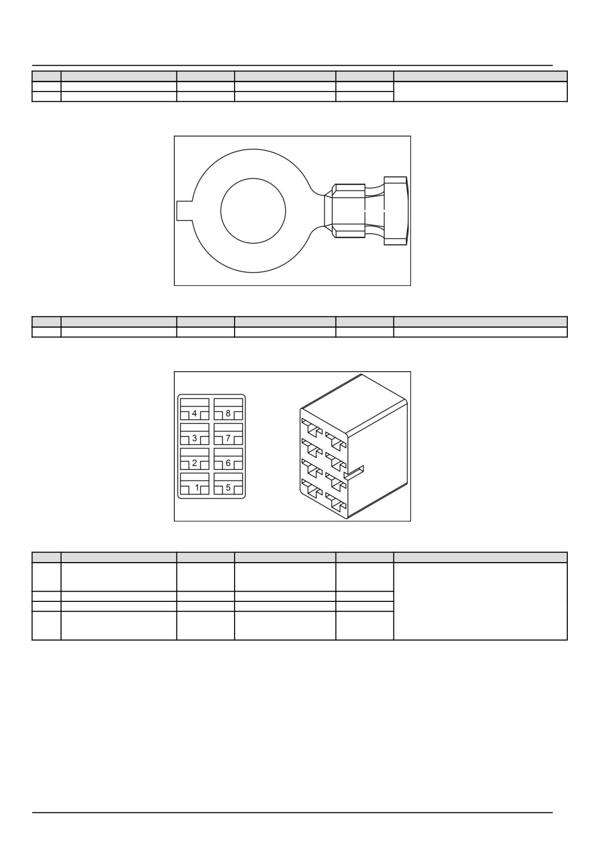
Electrical systems - Harnesses and connectors
Pin
From
Wire
Description
Color-Size
Frame
1
SP-051-P-X
051A
051A
YE/RD - 0.75
SHEET 09
2
SP-156-P-X
156
156
GY - 0.75
X-017 - FROM MEGA FUSE [ F-001] (84488487) (Male)
84488487
7
84488487
Pin
From
Wire
Description
Color-Size
Frame
1
SP-007-P-X
007
007
RD - 8.0
SHEET 03
X-018 - HOME ENTER SWITCH [ S-007] (87745329) (Female)
87745329
8
87745329
Pin
From
Wire
Description
Color-Size
Frame
1
X-050 (Female) pin 20
038
NAVIGATION SW ENTER
YE/GN - 0.75
SHEET 07
INSTRUMENT CLUSTER
CN-1
2
SP-006-P-X
005E
005E
BK - 0.75
3
SP-006-P-X
005F
005F
BK - 0.75
4
X-050 (Female) pin 21
039
NAVIGATION SW HOME
YE/BL - 0.75
INSTRUMENT CLUSTER
CN-1
55.4 [55.100] / 40