New Holland Tractor Workmaster 50 / Workmaster 60 / Workmaster 70 / Tier 4B (final). SERVICE MANUAL - page 13
Steering - Hydraulic control components
Power steering control valve - Inspect
Replace all seals and washers. Check all parts care-
fully. Make the necessary replacements.
41.2 [41.200] / 10
Steering - Hydraulic control components
Power steering control valve - Lubricate
Before assembly, lubricate all parts with hydraulic oil.
41.2 [41.200] / 11
Steering - Hydraulic control components
Power steering control valve - Assemble
WARNING
Avoid injury!
Handle all parts carefully. Do not place your hands or fingers between parts. Use Personal Protec-
tive Equipment (PPE) as indicated in this manual, including protective goggles, gloves, and safety
footwear.
Failure to comply could result in death or serious injury.
W0208A
CAUTION
Pinch hazard!
Always use suitable tools to align mating parts. DO NOT use your hand or fingers.
Failure to comply could result in minor or moderate injury.
C0044A
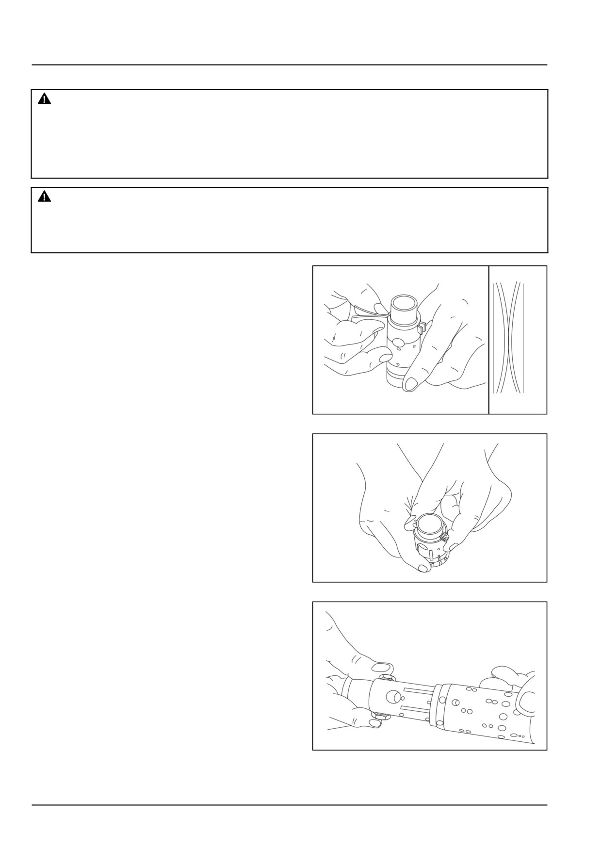
1. Place the two flat neutral position springs in the slot.
Place the curved springs between the flat ones and
press them into the place.
GNIL14TR04508AA
1
2. Line up the spring set.
GNIL14TR04509AA
2
3. Guide the spool into the sleeve. Make sure that spool
and sleeve are placed correctly in relation to each other.
GNIL14TR04510AA
3
41.2 [41.200] / 12
Steering - Hydraulic control components
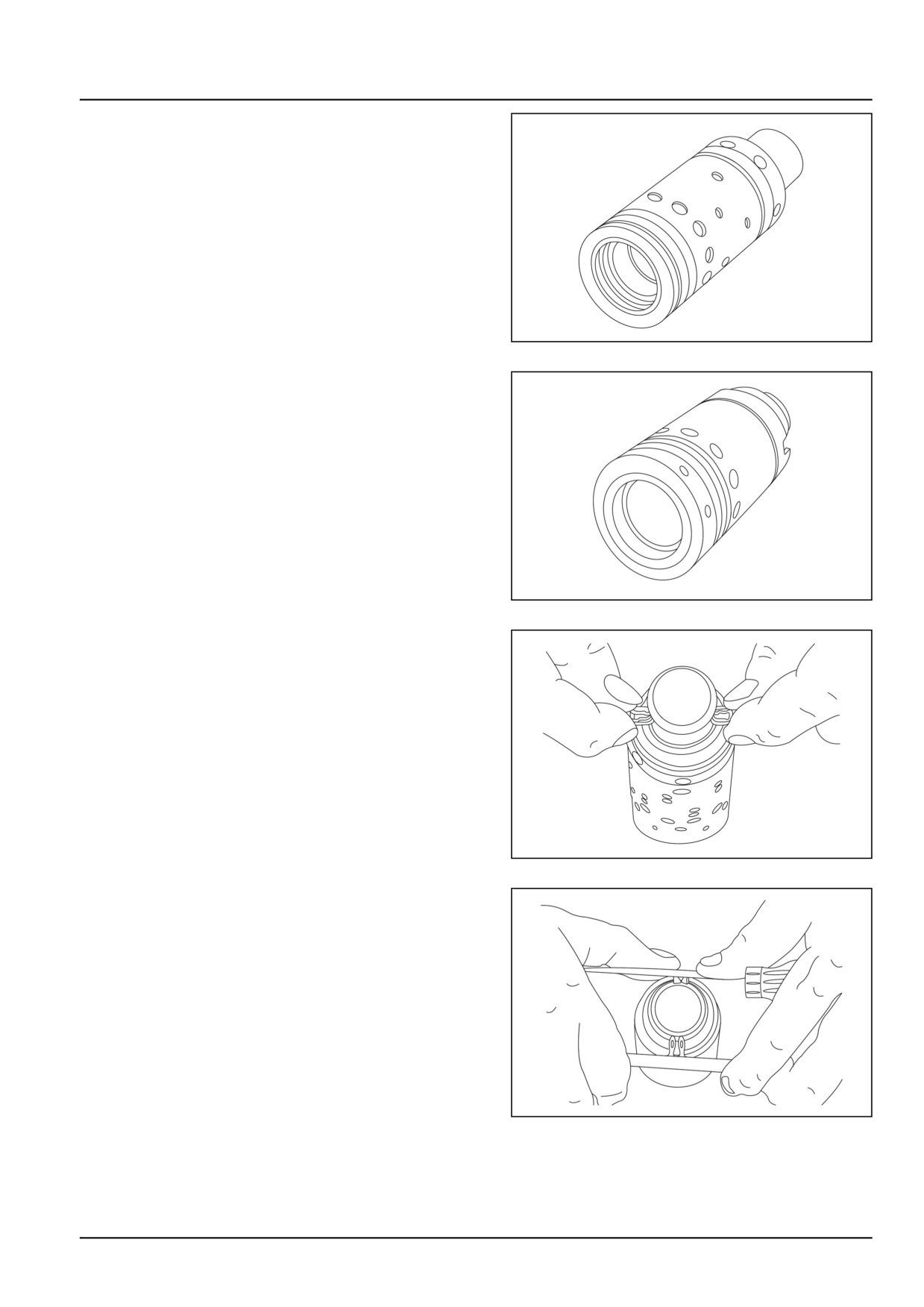
4. Assemble spool and sleeve.
GNIL14TR04511AA
4
NOTE: When assembling spool and sleeve, only two pos-
sible ways of positioning the spring slots are correct.
There are three slots in the spool and three holes in
the sleeve in the end of the spool/sleeve, opposite to
the end with speing slots. Place the slots and holes
opposite each other so that parts of the holes in the
sleeve are visible through the slots in the spool.
GNIL14TR04512AA
5
5. Press the springs together and push the neutral posi-
tion springs into place in the sleeve.
GNIL14TR04513AA
6
6. Line up the springs and centre them.
GNIL14TR04514AA
7
41.2 [41.200] / 13
Steering - Hydraulic control components
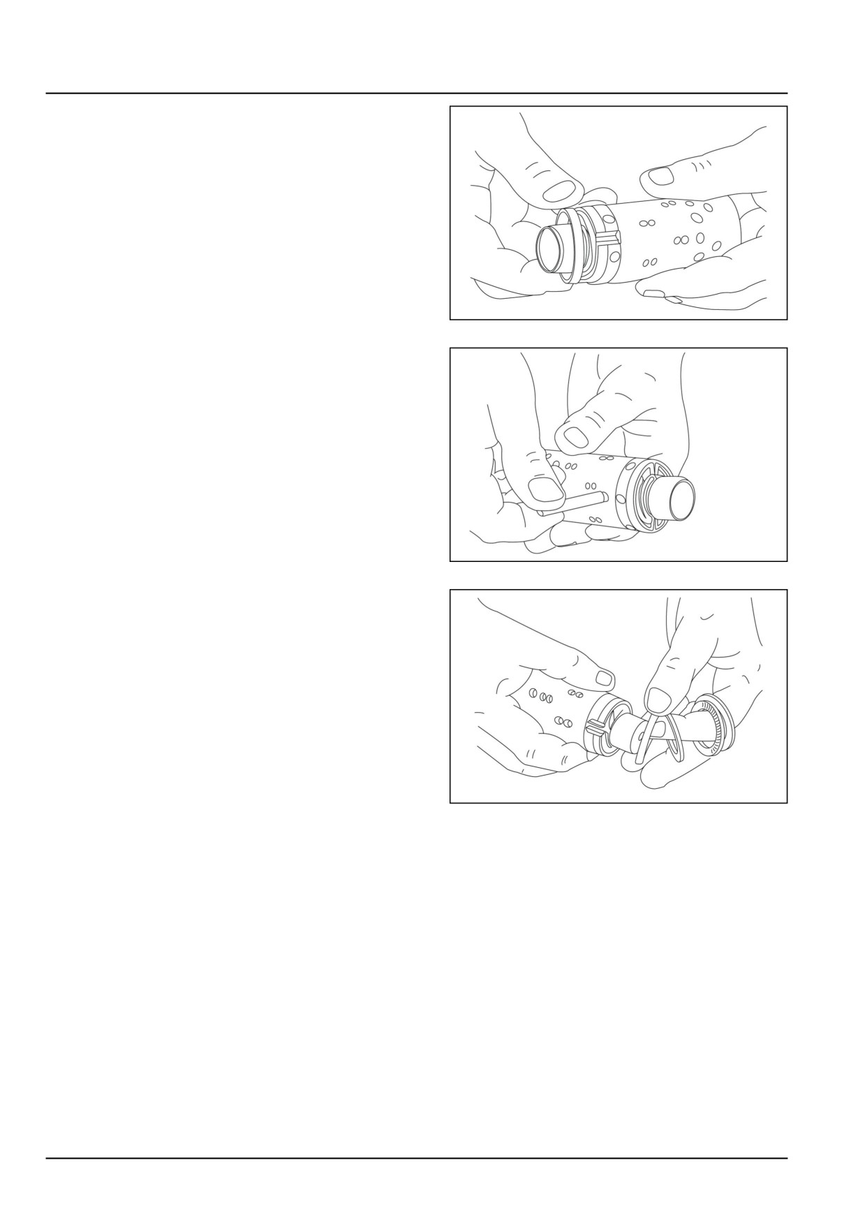
7. Guide the ring down over the sleeve.
NOTE: The ring should be able to move - free of the
springs.
GNIL14TR04515AA
8
8. Fit the cross pin into the spool/sleeve.
GNIL14TR04516AA
9
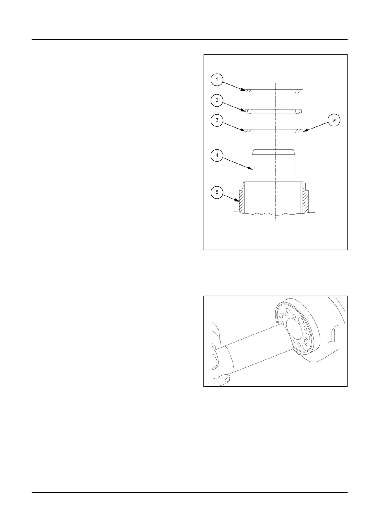
9. Fit bearing races and needle bearing as shown on be-
low drawing.
GNIL14TR04517AA
10
41.2 [41.200] / 14
Steering - Hydraulic control components
Assembly pattern for standard bearing
1. Outer bearing race
2. Needle bearing
3. Inner bearing race
4. Spool
5. Sleeve
GNIL14TR04518AB
11
*The inside chamfer on the inner bearing race must face
the inner spool.
Installation of O-ring
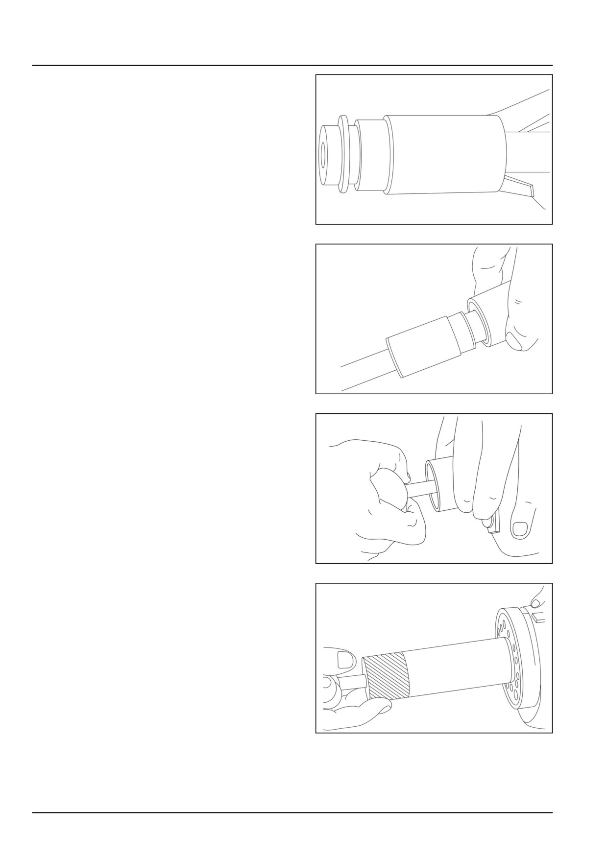
1. Turn the steering unit until the bore is horizontal in po-
sition. Guide the outer part of the assembly tool into
the bore for the spool/sleeve.
GNIL14TR04519AA
12
41.2 [41.200] / 15
Steering - Hydraulic control components
2. Grease O-ring and king ring/roto glyd with hydraulic oil
and place them on the tool.
GNIL14TR04520AA
13
3. Hold the outer part of the assembly tool in the bottom
of the steering unit housing and guide the inner part of
the tool right to the bottom.
GNIL14TR04521AA
14
4. Press and turn the O-ring/kin-ring into position in the
housing.
GNIL14TR04522AA
15
5. Draw the inner and outer parts of the assembly tool
out of the steering unit bore, leaving the guide from the
inner part in the bore.
GNIL14TR04523AA
16
41.2 [41.200] / 16
Steering - Hydraulic control components
Installation of lip seal
CAUTION
Pinch hazard!
Always use suitable tools to align mating parts.
DO NOT use your hand or fingers.
Failure to comply could result in minor or mod-
erate injury.
C0044A
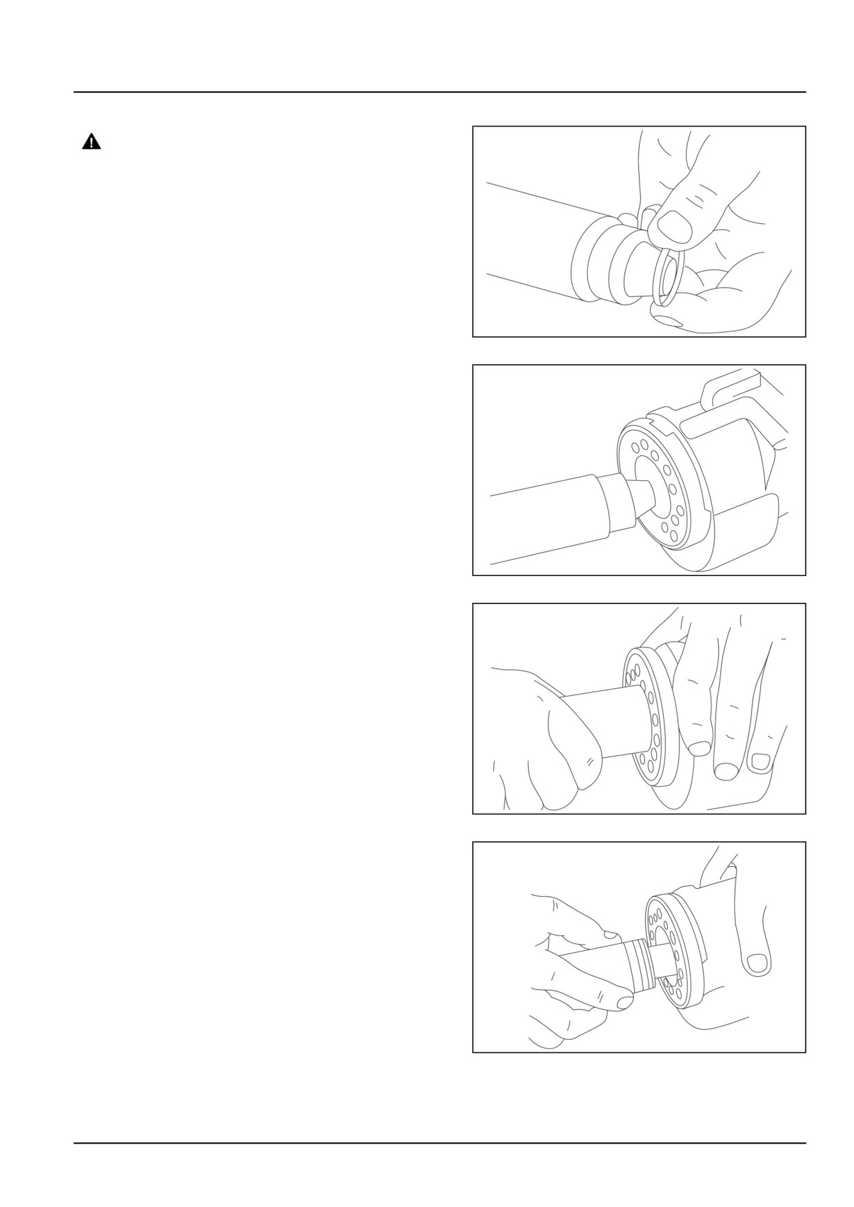
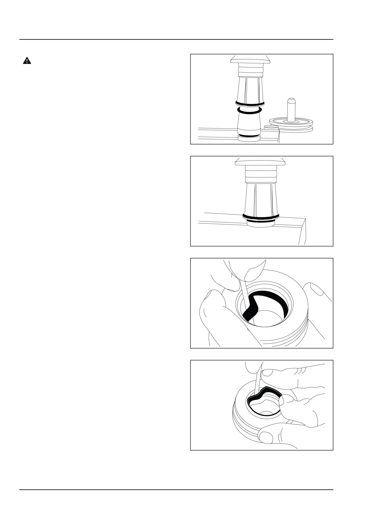
1. Lubricate the lip seal with hydraulic oil and place it on
the assembly tool.
GNIL14TR04524AA
17
2. Guide the assembly tool right to the bottom.
GNIL14TR04525AA
18
3. Press and turn the lip seal into place in the housing.
GNIL14TR04526AA
19
4. With a light turning movement, guide the spool and
sleeve into the bore.
NOTE: Fit the spool set holding the cross pin horizontal.
GNIL14TR04527AA
20
41.2 [41.200] / 17
Steering - Hydraulic control components
5. The spool set will push out the assembly tool guide.
The O-ring and kin ring/roto glyd are now in position.
GNIL14TR04528AA
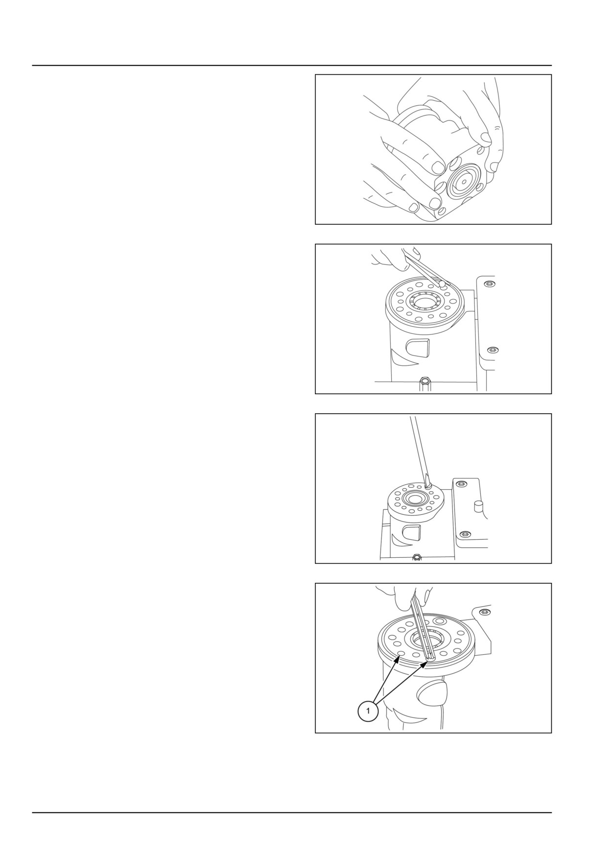
21
6. Turn the steering unit until the bore is vertical again.
Put the check valve ball into the hole indicated by the
arrow.
GNIL14TR04529AA
22
7. Screw the threaded bush lightly into the check valve
bore. The top of the bush must lie just below the sur-
face of the housing.
GNIL14TR04530AA
23
8. Place a ball in the two holes (1).
GNIL14TR04531AB
24
41.2 [41.200] / 18
Steering - Hydraulic control components
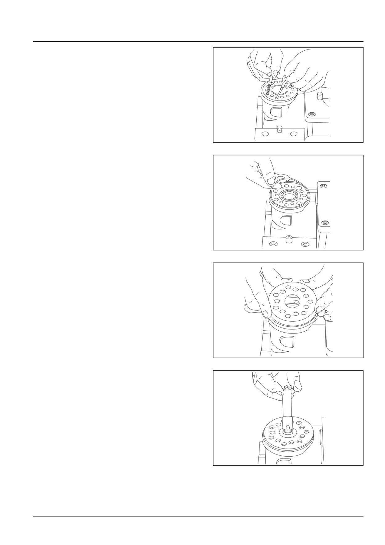
9. Place a new pin in the same two holes.
GNIL14TR04538AA
25
10. Grease the O-ring with mineral oil approximately vis-
cosity 500 mm2/s at 20 °C (68 °F).
GNIL14TR04532AA
26
11. Place the distributor plate so that the channel holes
match the holes in the housing.
GNIL14TR04533AA
27
12. Guide the cardan shaft down into the bore so that the
slot is parallel with the connection flange.
GNIL14TR04534AA
28
41.2 [41.200] / 19
Steering - Hydraulic control components
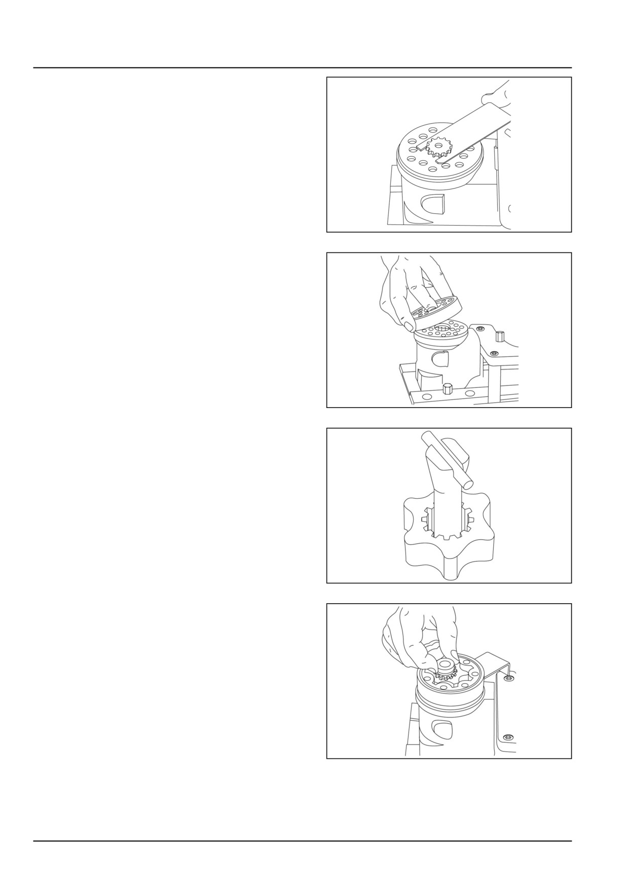
13. Place the cardan shaft as shown - so that it is held in
position by mounting fork.
GNIL14TR04535AA
29
14. Grease two O-rings with mineral oil approximately vis-
cosity 500 mm2/s at 20 °C (68 °F) and place them in
the two grooves in the gear rim. Fit the gearwheel and
rim on the cardan shaft.
GNIL14TR04536AA
30
NOTE: Fit the gear wheel (rotor) and cardon shaft so that a
tooth base in the rotor is positioned in relation to the shaft
slot as shown. Turn the gear rim so that the seven through
holes match the holes in the housing.
GNIL14TR04537AA
31
15. Fit the spacer, if any.
GNIL14TR04539AA
32
41.2 [41.200] / 20
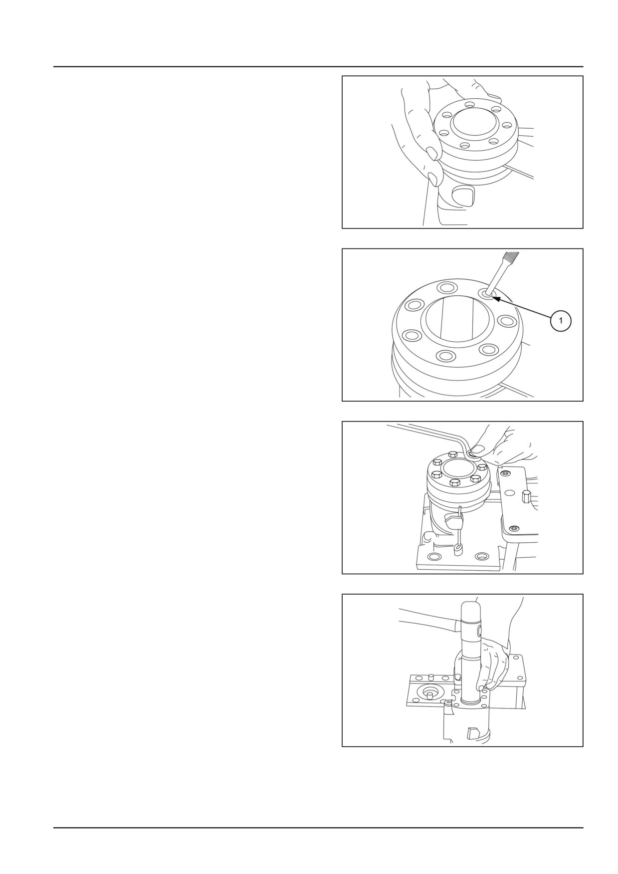
Steering - Hydraulic control components
16. Place the end cover in position.
GNIL14TR04540AA
33
17. Fit the special screw with washer and place it in the
hole (1).
GNIL14TR04541AB
34
18. Fit the six screws with washers and insert them.
Cross-tighten all the screws and the rolled pin with
a torque of 3.0 ± 0.6 daNm. The steering motor can
now be function tested.
GNIL14TR04542AA
35
19. Fit the dust seal ring in the housing using suitable tool
and a plastic hammer.
GNIL14TR04543AA
36
41.2 [41.200] / 21
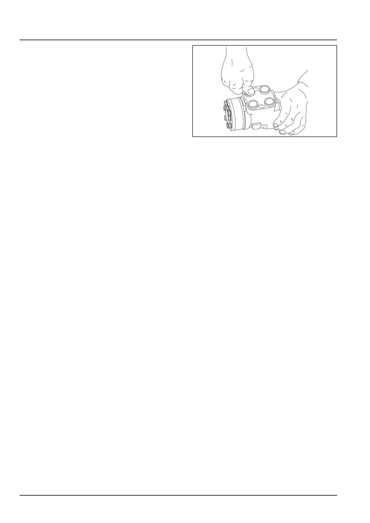
Steering - Hydraulic control components
20. Press the plastic plugs into the connection ports.
NOTE: Do not use a hammer.
GNIL14TR04544AA
37
41.2 [41.200] / 22
Steering - Hydraulic control components
Power steering control valve - Install
For installation, follow the removal process in reverse.
41.2 [41.200] / 23
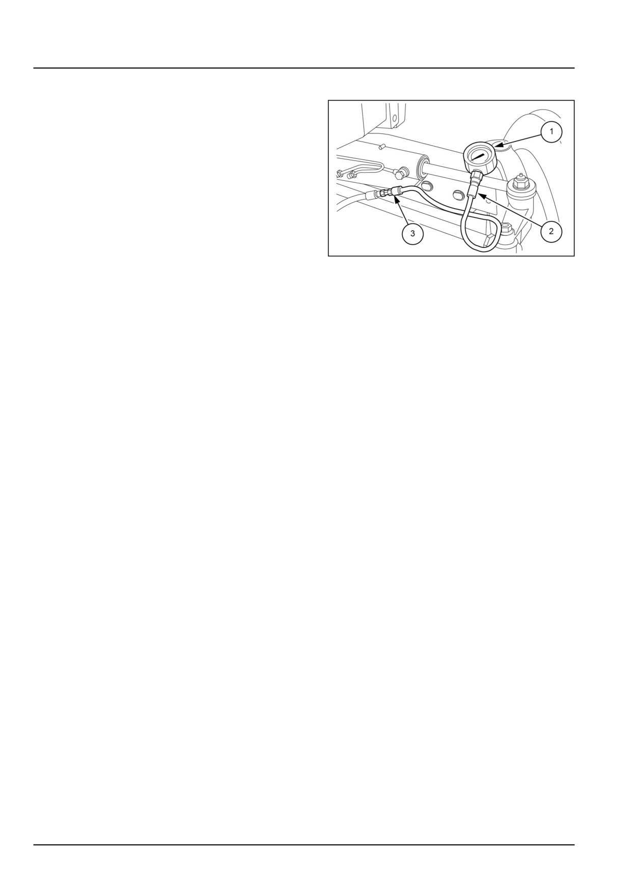
Steering - Hydraulic control components
Steering circuit relief valve - Pressure test
NOTE: There is no relief valve in steering pump and the
following pressure test must only be performed as speci-
fied below. Failure to observe this precaution may result in
severe damage to the hydraulic pump.
1. Turn steering onto full left-hand side lock.
2. Disconnect left-hand side turn feed hose at steering
cylinder.
3. Install power steering pressure checking kit.
(special
tool number 292870 with adapter 271318). As shown
in Fig.
1.
4. Start tractor and set engine speed to 1450 RPM. Turn
GNIL14TR04485AB
1
steering wheel to the left with a pull of approximately
22 N (5 lb) and observe the pressure reading.
NOTE: The use of a force greater than 22 N (5 lb) at the rim
of the steering wheel may lead to slightly inaccurate read-
ings due to the pumping action of the hydrostatic steering
motor.
If the steering test was satisfactory but pressure read-
ings are away from specification the relief valve in the
steering motor must be adjusted.
The pressure reading should be 110 - 125 bar (1595 -
1812 psi).
5. If the system pressure is not to specification proceed to
relief valve adjustment.
41.2 [41.200] / 24
Steering - Hydraulic control components
Steering circuit relief valve - Adjust
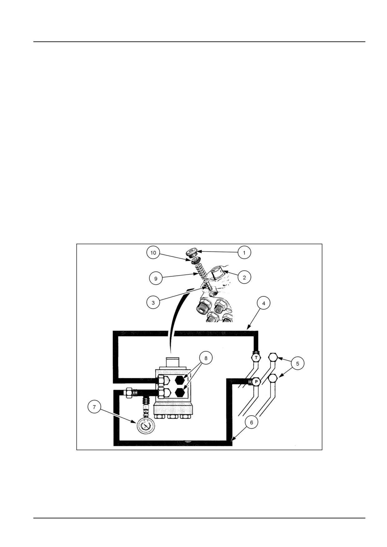
NOTE: To adjust the steering system relief valve it is necessary to remove the steering motor from the steering bracket,
to gain access to the hexagon headed adjusting screw.
1. Disconnect the steering motor from the steering
bracket, and remove from the tractor refer to Power
steering control valve - Remove (41.200)
2. Fabricate suitable test hose to connect pump pipeline
to steering motor. Connect locally procured ‘T’ joint be-
tween test hose and steering motor and Install pressure
gauge as in Figure 1.
3. Cap all connections to steering cylinder.
4. Connect the return hose normally. If required connect
with extra hose and suitable adopter.
5. Start the engine and idle between
1450
-
1500 RPM.Run the tractor until the transmission oil
reaches normal working temperature.
6. With the engine running, turn the steering motor shaft
to obtain full lock. The pressure gauge reading should
read 10300 kPa (1494 psi).
7. If the pressure readings are not correct, reset the ad-
juster, (1), using an 6 mm (0.2 in) hexagon key.
20096280
1
1.
Adjuster
6.
Hose for pump supply to steering motor
2.
Steering shaft
7.
Pressure gauge 20684 kPa (3000 psi)
3.
Relief valve
8.
Cap
4.
Steering Motor Output Hose
9.
Spring
5.
Tractor tubes to steering cylinder
10.
Plug
41.2 [41.200] / 25
Index
Steering - 41
Hydraulic control components - 200
Hydraulic steering oil reservoir - Remove
3
Power steering control valve - Assemble
12
Power steering control valve - Cleaning
9
Power steering control valve - Disassemble
5
Power steering control valve - Inspect
10
Power steering control valve - Install
23
Power steering control valve - Lubricate
11
Power steering control valve - Remove
4
Steering circuit relief valve - Adjust
25
Steering circuit relief valve - Pressure test
24
41.2 [41.200] / 26
Steering - 41
Pump - 206
Workmaster™ 50
Workmaster™ 60
Workmaster™ 70
41.3 [41.206] / 1
Contents
Steering - 41
Pump - 206
TECHNICAL DATA
Power steering pump
General specification
3
SERVICE
Pump
Remove
4
Install
5
41.3 [41.206] / 2
Steering - Pump
Power steering pump - General specification
Type
Gear type (In tandem with the hydraulic lift pump),
drawing oil from steering oil reservoir
Location
On the right-hand side of the engine
Mounting
Fitted on engine timing case and driven by timing gears
Make
Rexroth (Bosch Group)
Drive
Engine timing gears
Rotation (seen from the free end of the drive shaft)
Anti-clockwise
Displacement
8 cm³ per revolution
Max. rotational speed
3300 RPM
Flow at 1500 RPM & 210 bar
10.56 L/min
41.3 [41.206] / 3
Steering - Pump
Pump - Remove
Steering pump is in tandem with the hydraulic pump.
See Fixed displacement pump - Remove (35.104) for
steering pump removal.
41.3 [41.206] / 4
Steering - Pump
Pump - Install
For installation, follow the removal process in reverse.
41.3 [41.206] / 5
Index
Steering - 41
Pump - 206
Power steering pump - General specification
3
Pump - Install
5
Pump - Remove
4
41.3 [41.206] / 6
Steering - 41
Cylinders - 216
Workmaster™ 50
Workmaster™ 60
Workmaster™ 70
41.4 [41.216] / 1
Contents
Steering - 41
Cylinders - 216
SERVICE
Steering cylinder
Remove - 2WD
3
Overhaul
4
Install
9
41.4 [41.216] / 2
Steering - Cylinders
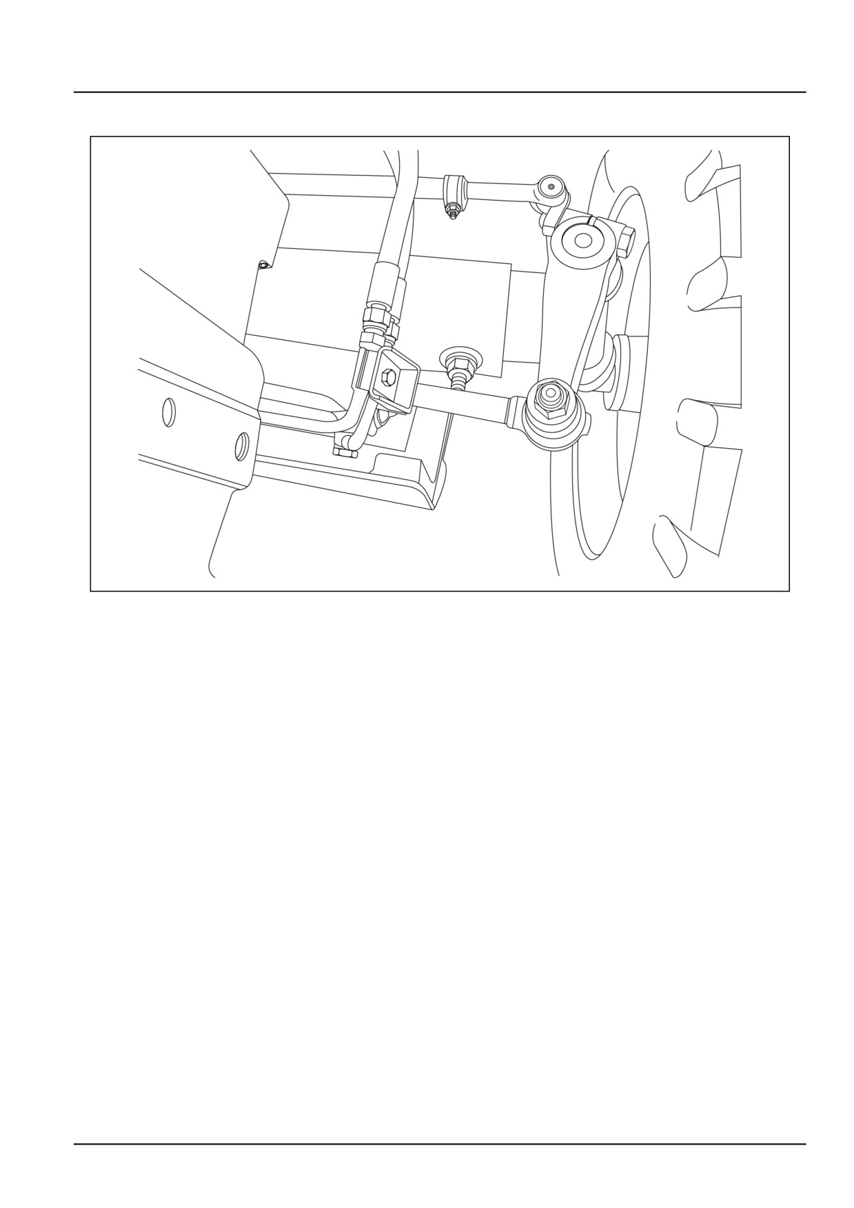
Steering cylinder - Remove - 2WD
GNIL14TR04545FB
1
1. Stand the tractor on a hard level surface and position
the front wheel in the straight ahead position.
2. Disconnect flexible pipes, cap the open pipe ends and
remove hose clamps.
NOTE: Position of flexible pipes and orientation of connec-
tors must be the same upon re-assembly.
3. Remove the nut securing the cylinder rod ball joint to
the steering arm and separate the joint, 1.
4. Remove the nut securing the steering cylinder on front
axle beam.
5. Remove the steering cylinder from the tractor and re-
trieve washer, spacer and bolt (pivot pin).
41.4 [41.216] / 3
Steering - Cylinders
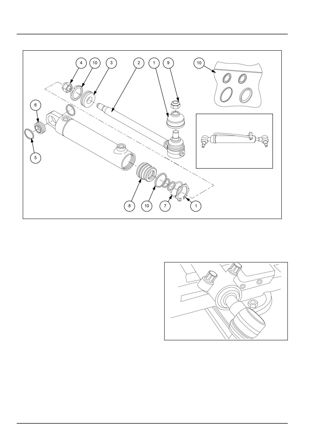
Steering cylinder - Overhaul
GNIL14TR04546FB
1
1.
Seeger (5 and 7 also)
5. Ball joint
2.
Assembled rod
6. Head
3.
Piston
7. Nut
4.
Lock nut
8. Seal kit
1. Fix the body taking care not to scratch it.
2. Push the rod to the end of the stroke (in the welded
side).
3. Use the seeger clamp to remove the head seeger.
4. Use the head bell and the plastic hammer to push the
head inside the body 20.00 - 30.00 mm (0.79 - 1.18 in).
GNIL14TR04548AA
2
41.4 [41.216] / 4
Steering - Cylinders
5. Remove the internal retaining ring with screw driver.
6. Remove the head hammering the rod. Remove the
piston after unscrew the self locking nut.
NOTE: Check that oil ports are not plugged and remove
internal oil.
GNIL14TR04547AA
3
7. Extract the rod by pulling. Seal on the piston could
require energetic action. Clamp the rod paying special
attention to not scratch its surface.
8. Remove with the screw driver piston seal and O-ring
under the seal.
GNIL14TR04549AA
4
9. Throw away used seal and open the seal kit and clean
the piston.
GNIL14TR04550AA
5
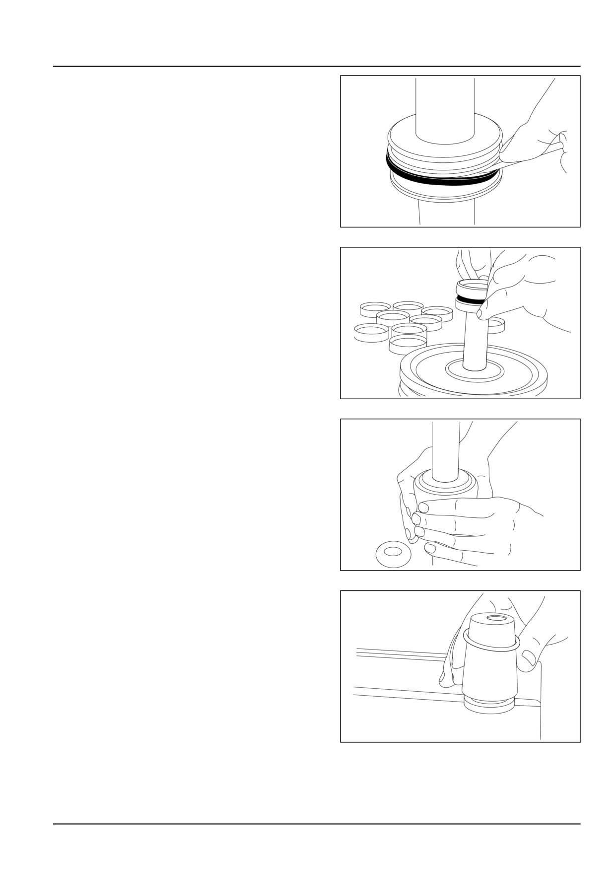
10. Apply piston seal mounting bell against piston and in-
sert the O-ring having it slipping on the bell.
GNIL14TR04551AB
6
41.4 [41.216] / 5
Steering - Cylinders
Installation of lip seal
CAUTION
Pinch hazard!
Always use suitable tools to align mating parts.
DO NOT use your hand or fingers.
Failure to comply could result in minor or mod-
erate injury.
C0044A
1. Lubricate the lip seal with hydraulic oil and place it on
the assembly tool.
GNIL14TR04552AA
7
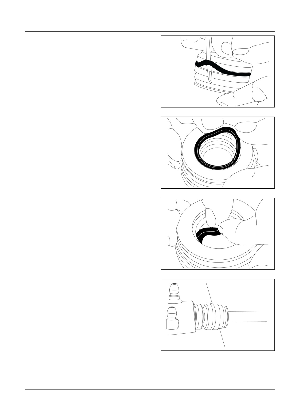
2. Insert the external ring of the piston seal over the O-ring
just mounted in this way. Position the ring over the bell,
take the pushing tool and overpass with it in the piston.
The seal will fit its groove automatically.
GNIL14TR04553AA
8
3. Calibrate the seal with the appropriate tool.
NOTICE: Use the screwdriver with care avoiding scratches
on seal grooves.
GNIL14TR04554AA
9
4. Remove seals on the head with the screw driver.
GNIL14TR04555AA
10
41.4 [41.216] / 6
Steering - Cylinders
5. Wash the head and verify whether the rags have been
generated during disassembling and working
GNIL14TR04556AA
11
6. Manual mount rod seal, taking care about the orienta-
tion of the lips. (Oriented to retain oil).
GNIL14TR04557AA
12
7. Mount manually the wiper (taking care about lip orien-
tation) and the static seal (external).
GNIL14TR04558AA
13
8. Draw the inner and outer parts of the assembly tool
out of the steering unit bore, leaving the guide from the
inner part in the bore.
9. Lubricate the lip seal with hydraulic oil and place it on
the assembly tool.
GNIL14TR04559AA
14
41.4 [41.216] / 7
Steering - Cylinders
Installation of lip seal
CAUTION
Pinch hazard!
Always use suitable tools to align mating parts.
DO NOT use your hand or fingers.
Failure to comply could result in minor or mod-
erate injury.
C0044A
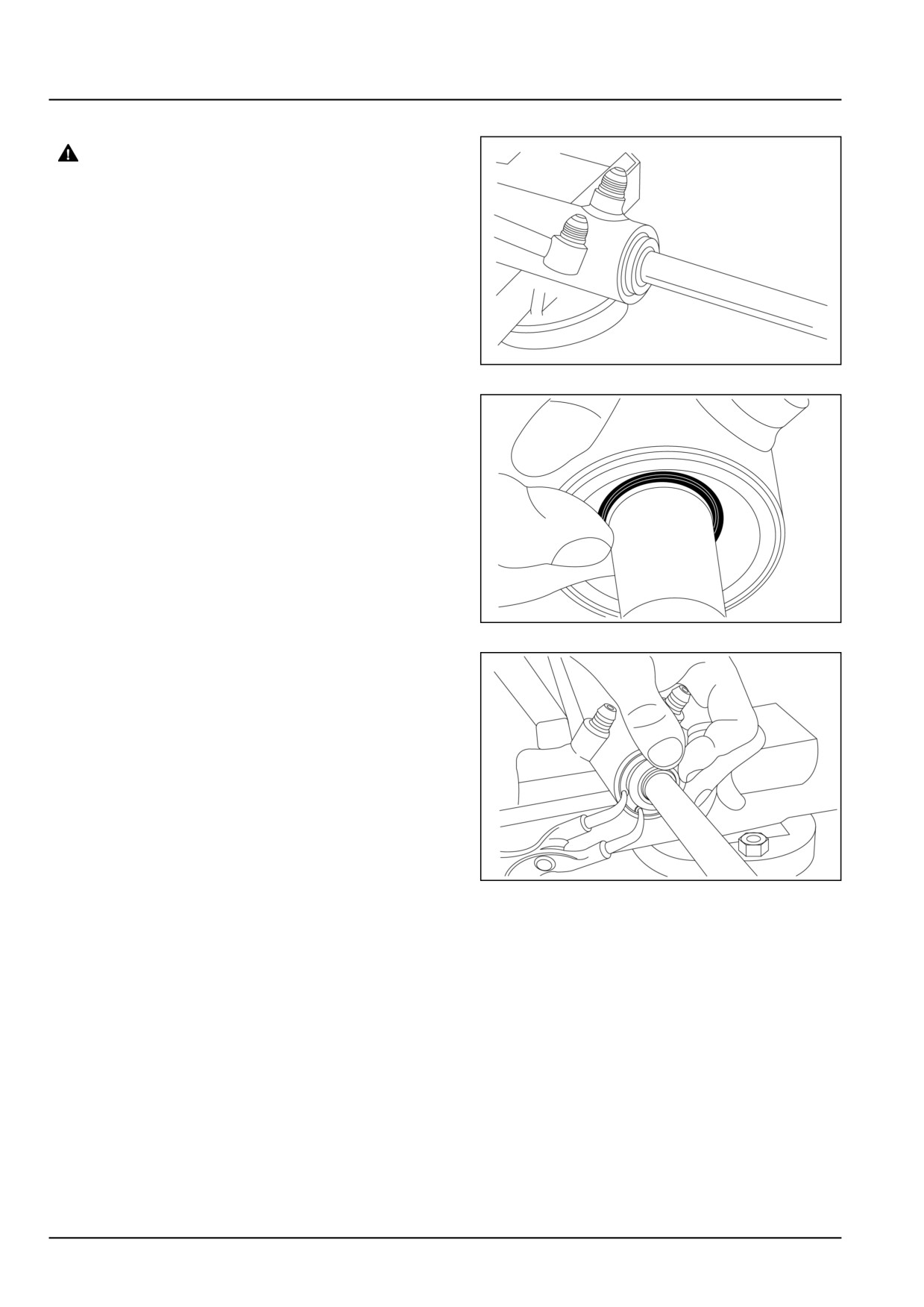
1. Insert the head and piston on rod-screw self locking
nut at torque (Nm). Grease every seal on body, head
and piston. Grease the internal wall of body ( 20.00 -
30.00 mm (0.79 - 1.18 in)) entrance zone.
GNIL14TR04560AA
15
2. Insert the assembled rod. Taking care to not damage
piston seal. Hammer the rod to end of stroke. Unscrew
the rod bell and screw on the other side.
GNIL14TR04561AA
16
3. Insert the head manually up to 20.00 - 30.00 mm (0.79
- 1.18 in) inside.
GNIL14TR04562AA
17
41.4 [41.216] / 8
Steering - Cylinders
Steering cylinder - Install
For installation, follow the removal process in reverse
order.
41.4 [41.216] / 9
Index
Steering - 41
Cylinders - 216
Steering cylinder - Install
9
Steering cylinder - Overhaul
4
Steering cylinder - Remove - 2WD
3
41.4 [41.216] / 10
CNH Industrial America New Holland Site 100 Brubaker Avenue New Holland, Pennsylvania United States
17557
SERVICE - Technical Publications & Tools
PRINTED IN U.S.A.
All rights reserved. No part of the text or illustrations of this publication may be reproduced.
NEW HOLLAND policy is one of continuous improvement and the right to change prices, specification or equipment
at any time without notices is reserved.
All data given in this publication is subject to production variations. Dimensions and weight are approximate only and
the illustrations do not necessarily show products in standard condition. For exact information about any particular
product, please consult your NEW HOLLAND Dealer.
EN
SERVICE MANUAL
Wheels
Workmaster™ 50
Workmaster™ 60
Workmaster™ 70
44
Contents
Wheels - 44
[44.511] Front wheels
44.1
[44.520] Rear wheels
44.2
44
Wheels - 44
Front wheels - 511
Workmaster™ 50
Workmaster™ 60
Workmaster™ 70
44.1 [44.511] / 1
Contents
Wheels - 44
Front wheels - 511
SERVICE
Front wheels
Test - 2WD
3
Toe in adjust - 2WD
4
Adjust
5
Adjust
7
44.1 [44.511] / 2
Wheels - Front wheels
Front wheels - Test - 2WD
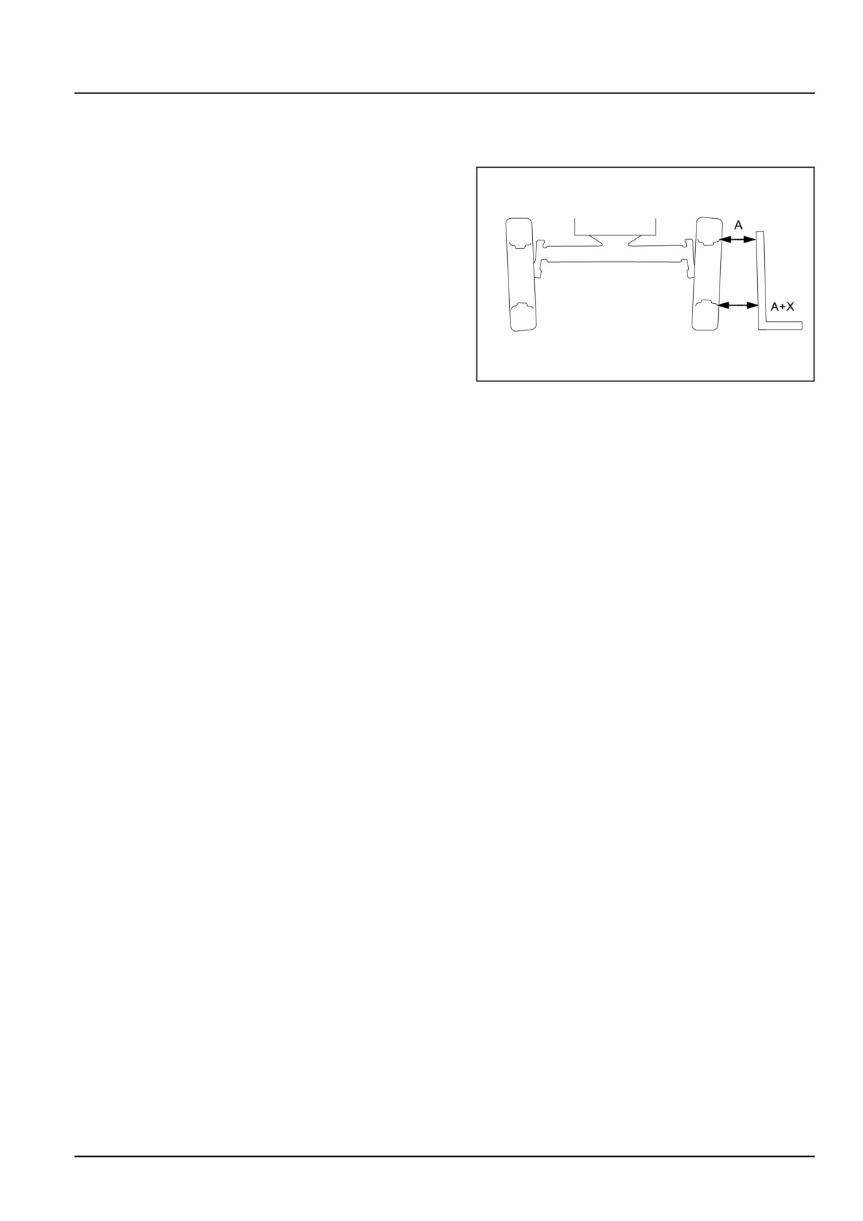
Wheel camber test
When the tractor moves along a straight line, wheels
should be tilted by 2 ° relative to the ground. Check
the front wheel camber that corresponds to a difference
(X) of approximately 15.0 mm (0.6 in) between the rim
edges.
GNIL14TR04457AB
1
44.1 [44.511] / 3
Wheels - Front wheels
Front wheels - Toe in adjust - 2WD
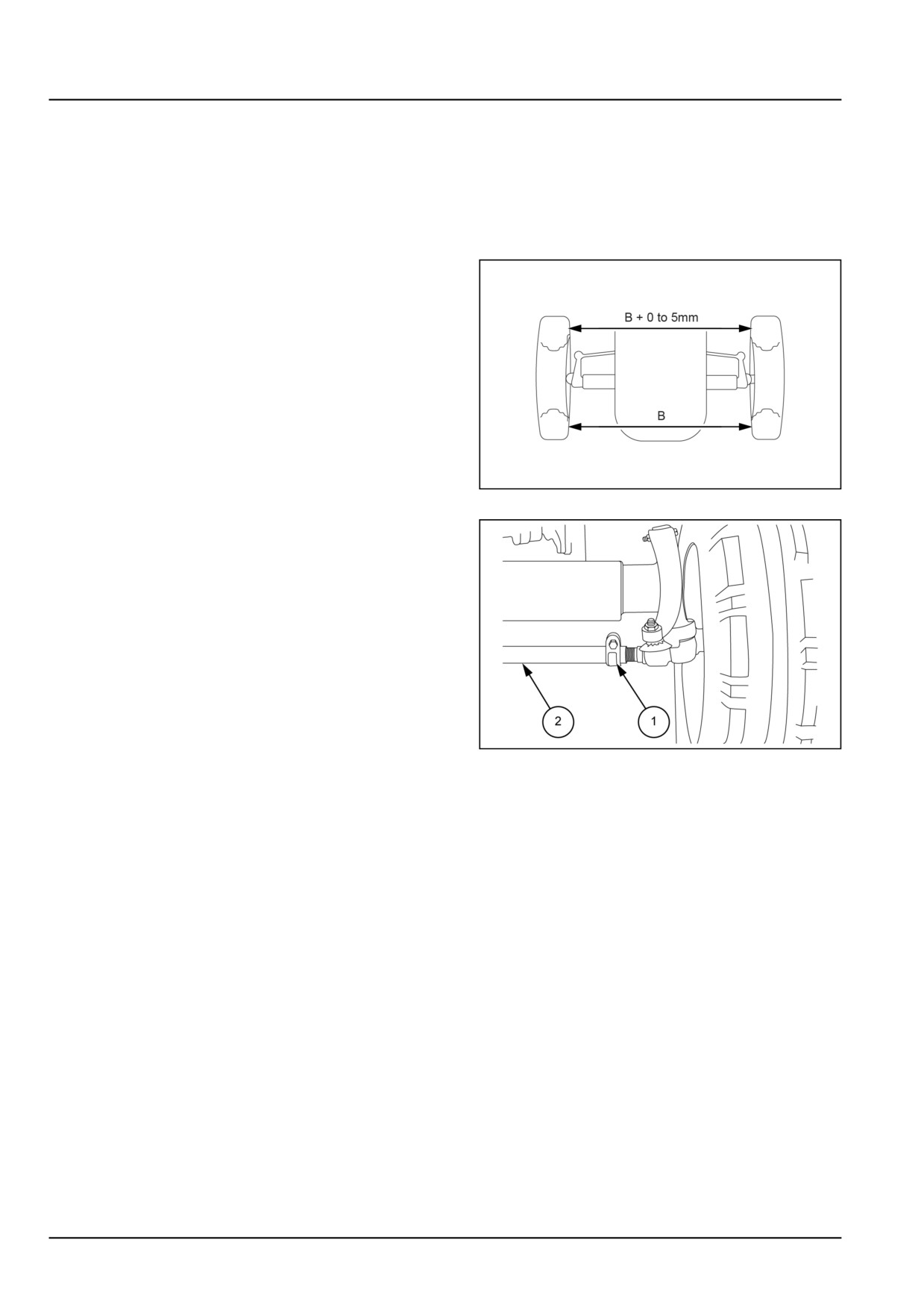
Front wheel toe-in test
When the tractor moves along a straight line, wheels
should be parallel to the tractor centre line or slightly
toe-in until a max. of 0.50 mm (0.02 in), measured be-
tween the rim edges.
Check the correct toe-in as follows:
1.
Inflate front tires to a pressure of 1.7 bar (25.0 psi).
2.
Place the steering wheel at mid-travel, with one spoke
along the tractor centre line.
3.
Check if wheels are parallel to the tractor centre line.
4.
Measure the distance (B) between the wheel inner rims
at hub height at the front of the wheels.
5.
Measure the distance between the wheel inner rims at
hub height at the rear of the wheels. The measurement
taken should be the same as (B) or greater by up to
5.00 mm (0.20 in) max.
GNIL14TR04458AB
1
6.
If it is necessary to adjust the front wheel toe-in, pro-
ceed as follows:
• Loosen the clamp (1) on both end of the track control
rod.
• Turn the track control rod (2) in or out to shorten or
lengthen the track control rod until desired toe-in is
achieved.
• Tighten the clamp (1).
GNIL14TR04459AB
2
44.1 [44.511] / 4