New Holland Tractor Workmaster 50 / Workmaster 60 / Workmaster 70 / Tier 4B (final). SERVICE MANUAL - page 11
Hydraulic systems - Main lift system
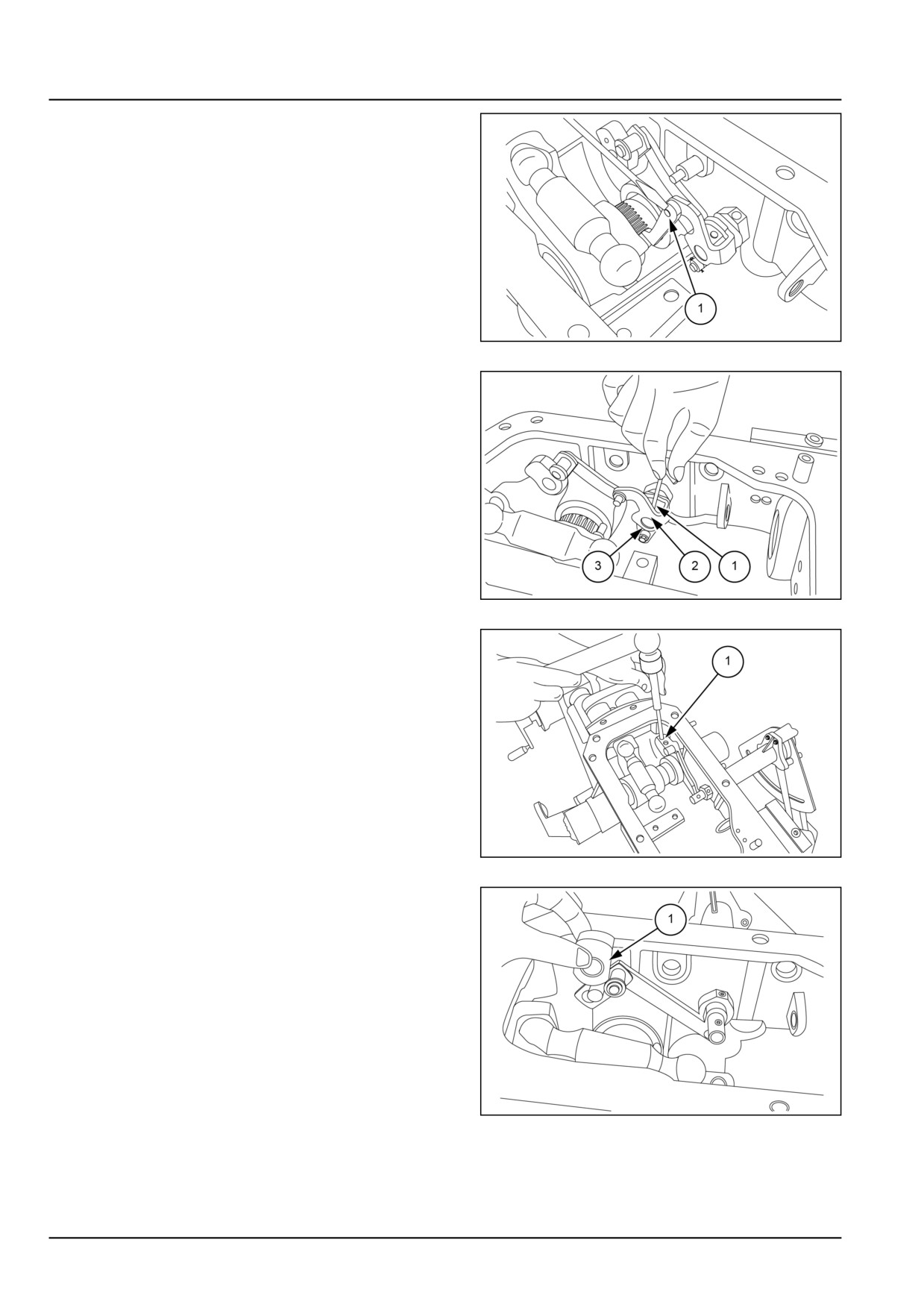
17. Remove link (1).
GNIL14TR04636AB
15
18. Unscrew locking screw (1) and remove position con-
trol cam (2) and bracket (3).
GNIL14TR04637AB
16
19. Remove dowel pin (1).
GNIL14TR04638AB
17
20. Remove cam (1).
GNIL14TR04639AB
18
35.2 [35.100] / 18
Hydraulic systems - Main lift system
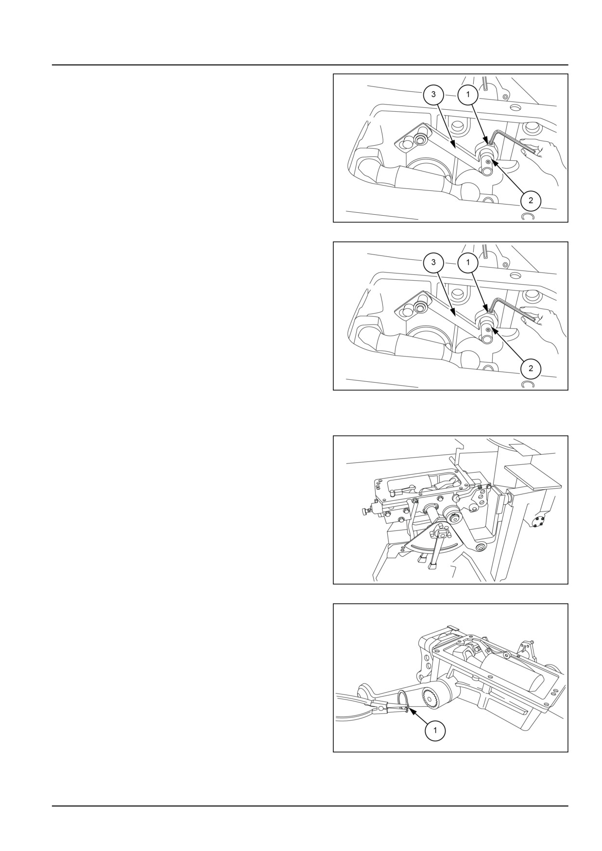
21. Remove lock (1) and disassemble link (2).
GNIL14TR04641AB
19
22. Unscrew locking screw (1) and disassemble lever (2)
along with link (3).
GNIL14TR04641AB
20
Lift arm shaft - removal
23. Remove lift assembly from the tractor and fix it on a
rotary stand. Refer to Main lift system - Remove
(35.100).
GNIL14TR04642AA
21
24. Remove the circlip (1) from lift arm shaft.
GNIL14TR04643AB
22
35.2 [35.100] / 19
Hydraulic systems - Main lift system
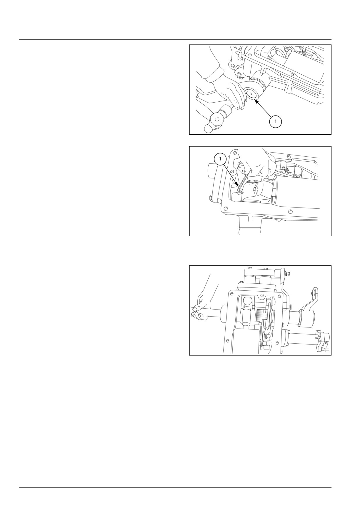
25. Remove the lift arm from the shaft.
NOTE: Before removing lift arm punch a mark (1) on both
lift arm and shaft to facilitate the assembly in original posi-
tion.
GNIL14TR04644AB
23
26. Repeat the same for the other side lift arm.
GNIL14TR04645AB
24
27. Remove the locking sensor (1) locking crank and
shaft.
28. Push the shaft from left-hand side towards right-hand
side by hammering gently using aluminium or copper
rod.
GNIL14TR04646AA
25
35.2 [35.100] / 20
Hydraulic systems - Main lift system
Main lift system - Assemble
Draft sensing unit
Assemble and reinstall sensing unit on hydraulic hous-
ing observing the following:
1. Assembly and reinstallation follows the removal proce-
dure is reverse from step 7 to step 1.
2. Tighten all fasteners to correct torque. See Main lift
system - Torque (35.100).
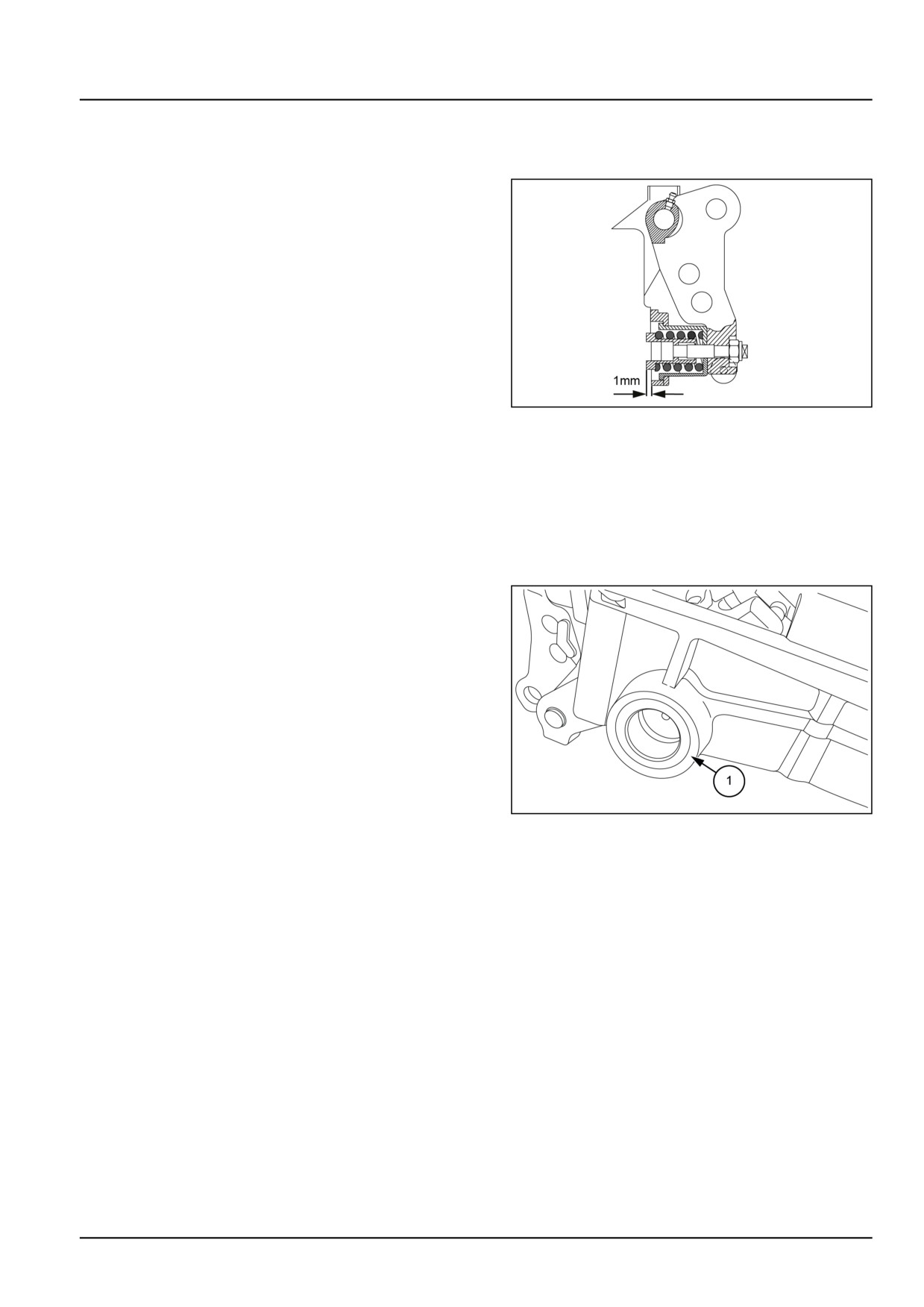
3. The top face of spring roller:
• Should be 1.000 mm (0.039 in) above the top face
of flange.
• In case, if it is less add shims and if more remove
shims.
GNIL14TR04622AA
1
4. Refer to page for correct settings.
Rear lift internal controls
5. Re-assembling follows disassembly procedure in re-
verse.
Lift arm shaft
6. Reinstall the shaft and lift arm in the lift housing observ-
ing the following:
• Reinstallation follows the removal procedure in re-
verse. Refer to Main lift system - Disassemble
(35.100) from step 6 to step 1.
• See Main lift system - Install (35.100) for reinstal-
lation of lift assembly on tractor.
• Check the seals (1) and replace if required.
• Use special tool number 9970873 to fix the seal.
• Tighten all fasteners to correct torque as detailed in
Main lift system - Torque (35.100).
GNIL14TR04647AB
2
35.2 [35.100] / 21
Hydraulic systems - Main lift system
Main lift system - Adjust
In case of complete disassembly of the lift it is neces-
sary to make the following adjustments:
A. Control valve sensitivity setting
B. Position control lever setting
C. Draft control lever setting
D. Reaction spring setting
E. Internal push rod setting
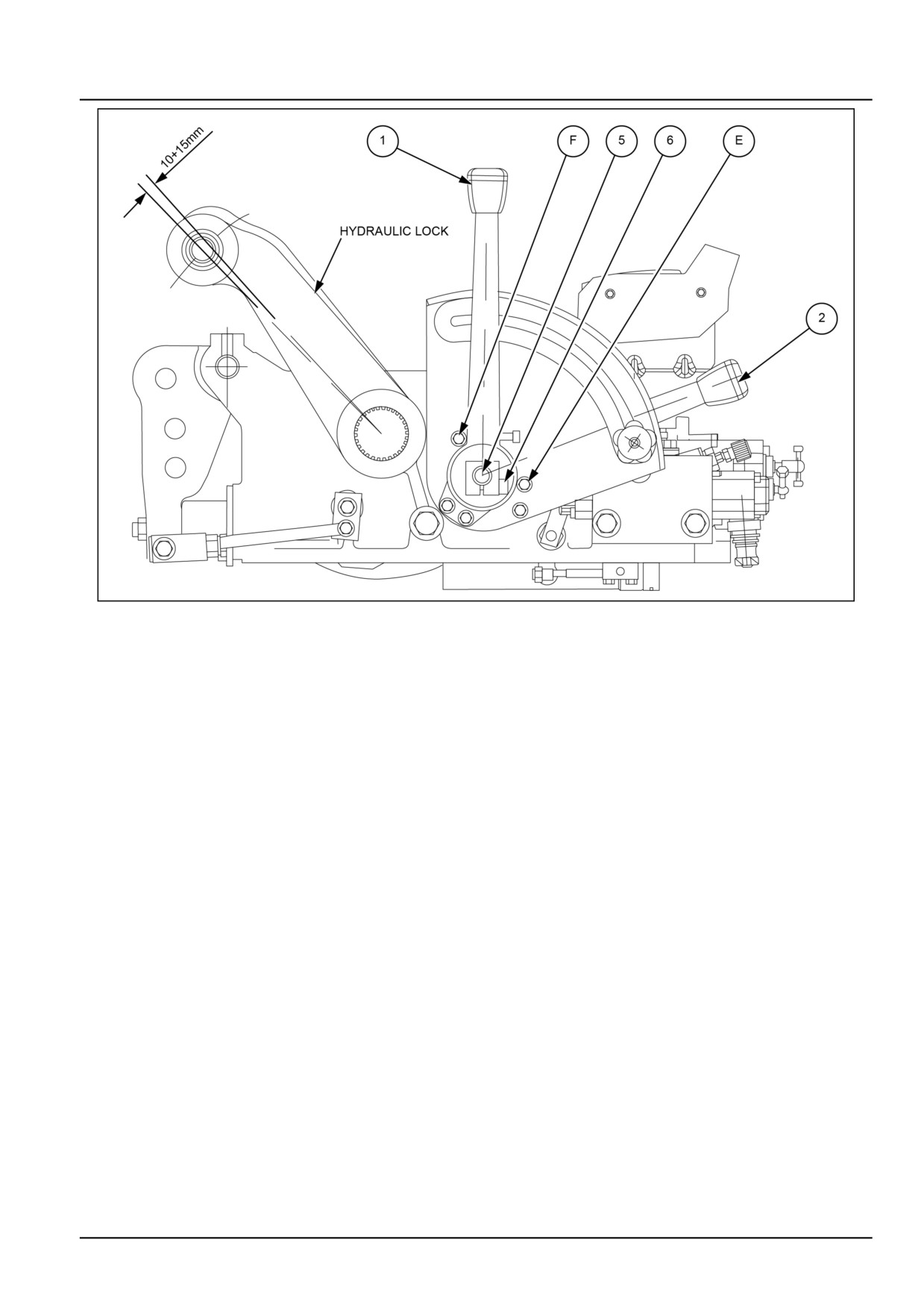
A. Position control lever setting
With reference to 1.
The adjustment is carried out in order to establish the
maximum raised position of the rockshaft’s lifting arms.
Completely lower the arms and apply a light weight
which creates a pressure in the cylinder of 50 - 60 bar
(725 - 870 psi).
Loosen the fastening screw (6) so as to free the position
control lever (1) from the shaft (5).
With the draft control lever (2) at its lowest position
against the backstop (E) raise the position control lever
(1) against the backstop (F).
Maintaining fixed the levers (1) and (2) and with a
13.0 mm (0.5 in) open end wrench rotate slowly in an
anti-clockwise direction the position control shaft (5) so
as to raise the arms to their maximum raised position
which is determined by the internal hydraulic limit stop.
Since during the functioning of the position control the
hydraulic limit stop must not be triggered it is neces-
sary to have a safety margin of ~ 10.0 - 15.0 mm (0.4 -
0.6 in).
In order to do this, rotate slowly in a clockwise direction
the shaft (5) until the arms are lowered by the required
safety margin.
At this point keep the shaft (5) fixed and with lever (1)
against the backstop (F) keep the lever fixed with the
shaft by tightening fully the fastening screw (6).
To control, raise completely the arms by moving the po-
sition control lever (1) against the backstop (F) raising
completely the draft control lever (2) there is a further
movement upwards of the rockshaft arms. This move-
ment should be contained within 15.0 - 20.0 mm (0.6 -
0.8 in).
35.2 [35.100] / 22
Hydraulic systems - Main lift system
GNIL14TR04652FB
1
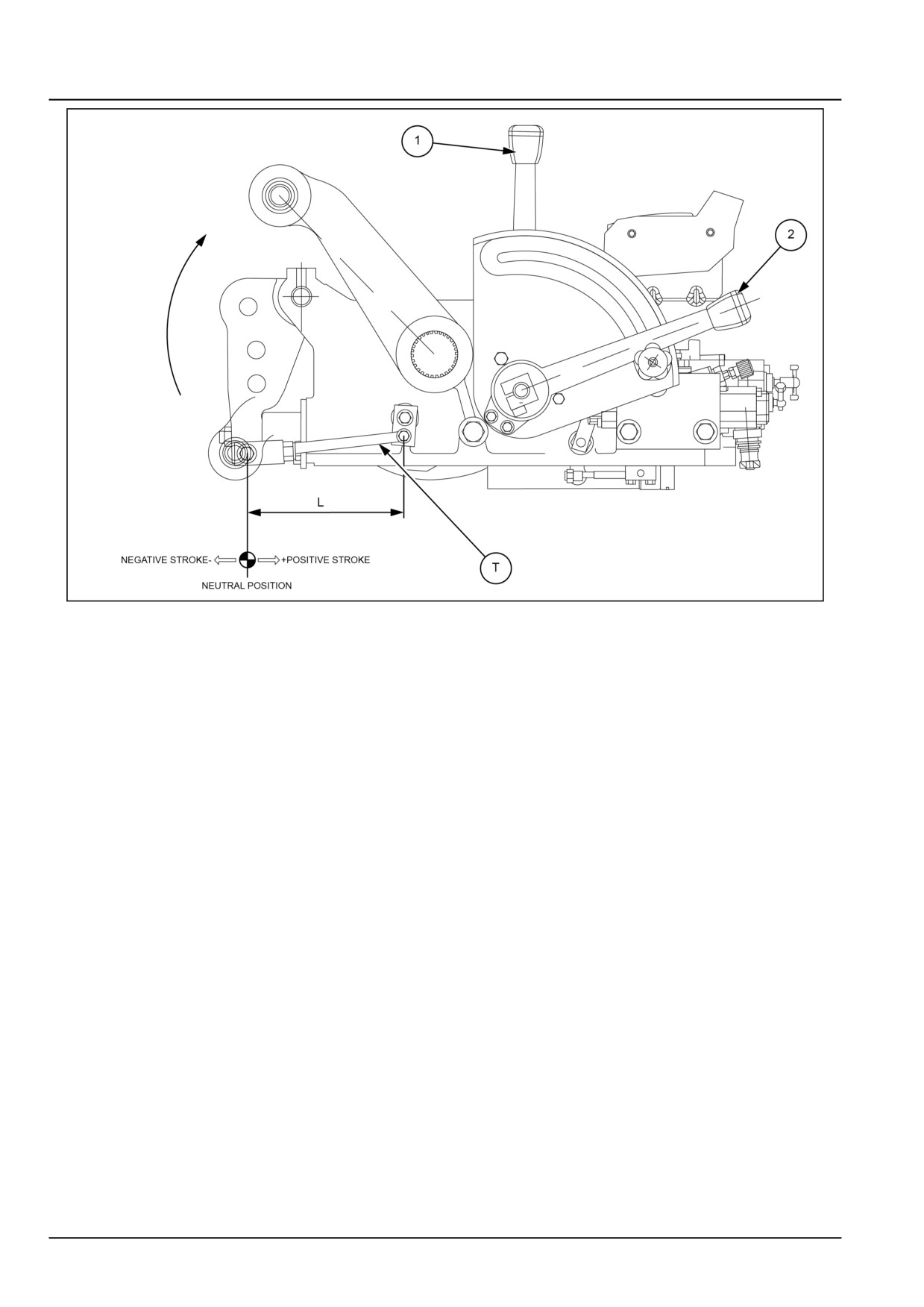
B. Draft control lever setting
With reference to 2.
The adjustment of the draft control lever must be carried
out to have a correct synchronisation between this lever
and the stroke (positive and negative) of the top link
bracket in order to make full use of the reaction spring.
The adjustment must be carried out without implements
or loads applied to the three point linkage (20) (i.e. in a
neutral position).
Position the two control levers (1) and (2) in the lowest
position.
With the motor running at minimum RPM slowly raise
the draft control lever (2).
The adjustment of the draft lever (2) is correct when it
is moved upward to the (6-8) sign on the sector and this
allows the arms to be completely raised.
If the lever (2) raises completely the arms before arriv-
ing at the (6-8) sign on the sector then the measurement
(L) of the rod (T) must be shortened.
If the lever (2) raises completely the arms after passing
the (6-8) sign on the sector then the measurement (L)
of the rod (T) must be lengthened.
NOTE: The position of the lever (1) establishes only the
position of the arms but does not influence the adjustment
of the draft control lever (2).
35.2 [35.100] / 23
Hydraulic systems - Main lift system
GNIL14TR04653FB
2
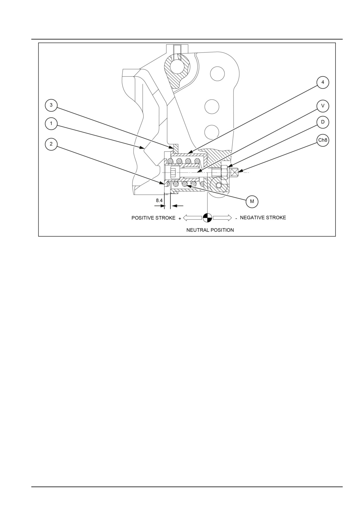
C. Reaction spring setting
With reference to figure 3.
For a correct functioning of the rockshaft the top link
bracket, when it is not working, must not have an axial
play in the positive (+) and negative (-).
After having carried out a correct assembly, the spring
holder (2) must rest against the rockshaft housing (1),
while the spring holder cover (4) must rest against the
flange (3).
In this condition the spring (M) is set to a preload of 0.30
- 0.60 mm (0.01 - 0.02 in).
Before assembling the complete reaction assembly to
the rockshaft housing a pre-assembly of the spring (M)
is needed in order to obtain a measurement of about
8.40 mm (0.33 in).
After carrying out the reaction assembly a definitive ad-
justment is made:
Keep the screw (V) fixed with an 8.00 mm (0.31 in)
wrench and adjust the self-locking nut (D) by tightening
or loosening it gradually in order to eliminate the axial
play completely.
35.2 [35.100] / 24
Hydraulic systems - Main lift system
GNIL14TR04654FB
3
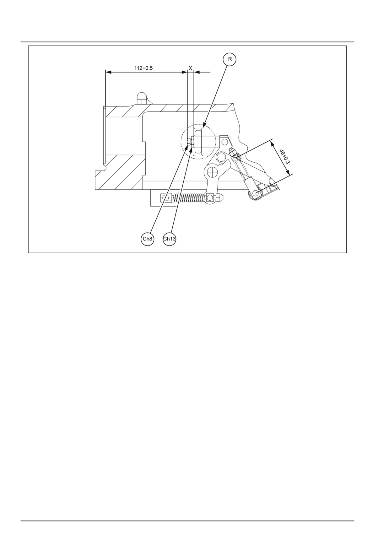
D. Internal push rod setting
With reference to figure 4.
If the rockshaft is disassembled and if the regulator (R)
must be changed it is advisable to control the measure-
ment “X” (~10,5) in order to re-assemble the push rod
in the same position.
Ensure also that the measurement of the spring is 46.00
- 46.30 mm (1.81 - 1.82 in).
The control of the measurement of the push rod with re-
spect to the control valve face is carried out after making
all the adjustments (sensitivity of control valve - position
control lever - draft control lever).
With the rock shaft’s arms completely lowered and with-
out loads or implements on the three point linkage (neu-
tral position), position the two control levers (1) and (2)
at their lower position against the backstop (F).
In this position push the push rod and verify with
the appropriate gauge that the distance of 112.00 -
112.50 mm (4.41 - 4.43 in) is correct.
NOTE: If the measurement “X” is changed it is obligatory
to carry out again the adjustment of the position and draft
control levers.
35.2 [35.100] / 25
Hydraulic systems - Main lift system
GNIL14TR04655FB
4
35.2 [35.100] / 26
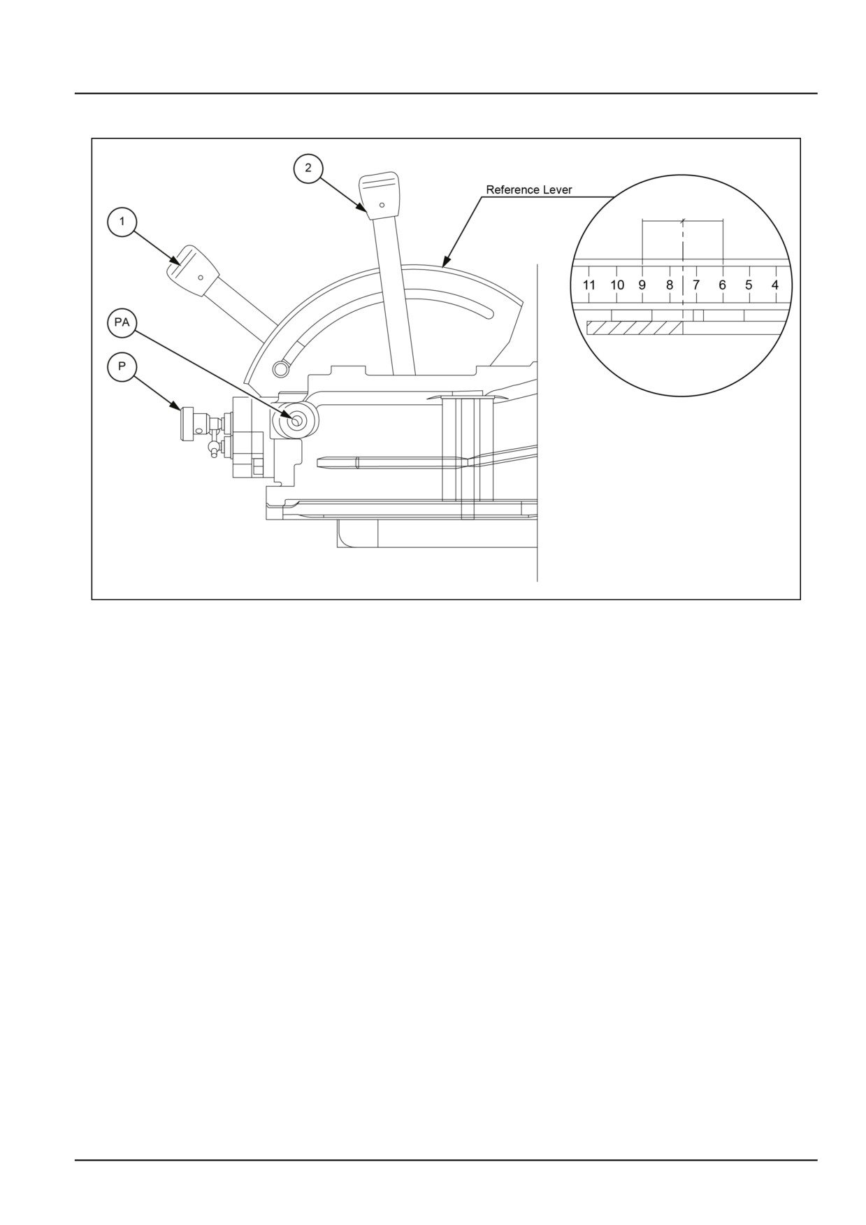
Hydraulic systems - Main lift system
Main lift system - Inspect
GNIL14TR04650FB
1
The pre selector (P) is used to connect the auxiliary
port-thread M18 x 1.5 and send the oil to a single acting
cylinder-for example a wagon dump-and moving it with
the draft lever (2).
In this way the oil that normally is filling the rock-shaft
cylinder is deviated to the external cylinder.
• Connect the port (PA) to the single acting usage e.g.
Wagon dump cylinder.
• For safety fully lower the lift arms by putting down
both draft and position levers.
• Screw completely the pre selector (P) in order to
block the oil passage to the rock shaft cylinder.
• To obtain the acting of external cylinder move up
slowly the draft lever (2). If the top link bracket is
in neutral position (without any implement attached)
the effect starts when the lever (2) is between num-
bers 9-6 on the sector.
• To obtain the stop of the acting move back down a
little the draft lever.
• To obtain the discharge - cylinder closing - lower
down fully the draft lever (2).
NOTE: In the acting phase-external cylinder opening-if the
single acting arrives to the end of the stroke the relief valve
enters in action with the possibility to damage the pump if
the system is left for a long time in this position.
35.2 [35.100] / 27
Hydraulic systems - Main lift system
Therefore after having reached the required movement
of the cylinder it is important to not forget to move back
down a little the lever (2) in order to stop the cylinder or
to discharge the oil.
35.2 [35.100] / 28
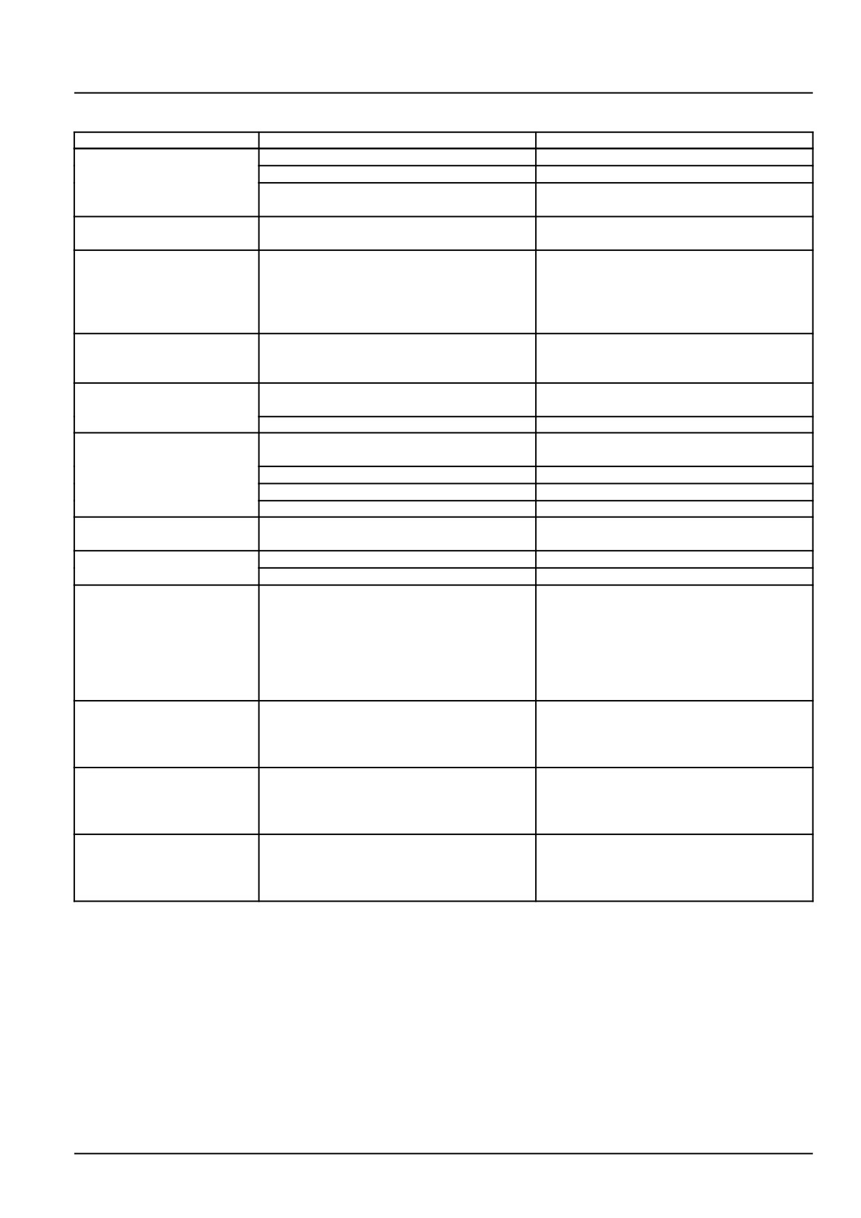
Hydraulic systems - Main lift system
Main lift system - Troubleshooting
Problem
Possible Cause
Correction
The Rockshaft lifts jerkily
Insufficient oil level in the tank
Top up the level
Pump inlet filter clogged
Clean or replace the filter
Infiltration of air into the pump inlet pipe
Check the inlet pipe and any coupling and
gasket
Rockshaft does not
Differential valve blocked or dirty
Remove the control valve and unblock the
operate
regulator piston
The rock shaft starts to
Tension rod measurement (L) is not cor-
Adjust the draft control lever (Refer to Main
lift, but it stops as soon as
rect (Refer to Main lift system - Adjust
lift system - Adjust (35.100))
it feels the load, without
(35.100))
the functioning of the
over-pressure valve
The rock shaft does not
Faulty adjustment of the position control
Adjust position control lever (Refer to Main
descend over its entire
lever (1)
lift system - Adjust (35.100))
travel
The rock shaft does not
Discharge valve blocked
Remove control valve and unblock or clean
descend
discharge valve
Lever RD closed
Turn lever RD in anti-clockwise
Lifting capacity does not
Deterioration of the control valve seal rings
Remove control valve and replace the ex-
match that prescribed
ternal seal rings
Relief and safety valves out or calibration
Control calibration of the valves
Poor pump efficiency
Replace the pump
Excessive loss of oil from control valve
Overhaul the control valve
The rock shaft supports
Piston gasket worn
Replace the gasket
loads with difficulty
When the motor is off
Oil leakage from safety valve
Remove control valve and adjust valve
Oil leakage from check valve
Remove the control valve and adjust valve
With the arms raised at
Incorrectly adjusted of position control lever
Adjust the position control lever (Refer to
backstop and with the
which, at maximum raised height, causes
Main lift system - Adjust (35.100))
engine on, we have
the internal automatic backstop to function
verified a rhythmic
oscillation, with the
engine off the load does
not lower
The draft control does not
Draft control lever is adjusted badly
Adjust the draft control lever ( Main lift sys-
function, the rock shaft
tem - Adjust (35.100)).
raises and lowers only
with the position lever
The position control does
Position control lever is adjusted badly
Adjust the position control lever (Refer to
not function, the rock
Main lift system - Adjust (35.100))
shaft raises and lowers
only with the draft lever
Rockshaft does not lift
Pre selector i s fully closed
Unscrew fully the pre-selector (P) (Refer to
and the relief valve acts
Main lift system - Adjust (35.100)).
with the possibility to
damage the pump
35.2 [35.100] / 29
Index
Hydraulic systems - 35
Main lift system - 100
Main lift system - Adjust
22
Main lift system - Assemble
21
Main lift system - Disassemble
14
Main lift system - Dynamic description
6
Main lift system - General specification
3
Main lift system - Inspect
27
Main lift system - Install
13
Main lift system - Remove
11
Main lift system - Sealing
4
Main lift system - Special tools
5
Main lift system - Torque
3
Main lift system - Troubleshooting
29
35.2 [35.100] / 30
Hydraulic systems - 35
Fixed displacement pump - 104
Workmaster™ 50
Workmaster™ 60
Workmaster™ 70
35.3 [35.104] / 1
Contents
Hydraulic systems - 35
Fixed displacement pump - 104
TECHNICAL DATA
Fixed displacement pump
General specification
3
SERVICE
Fixed displacement pump
Remove
4
Install
6
35.3 [35.104] / 2
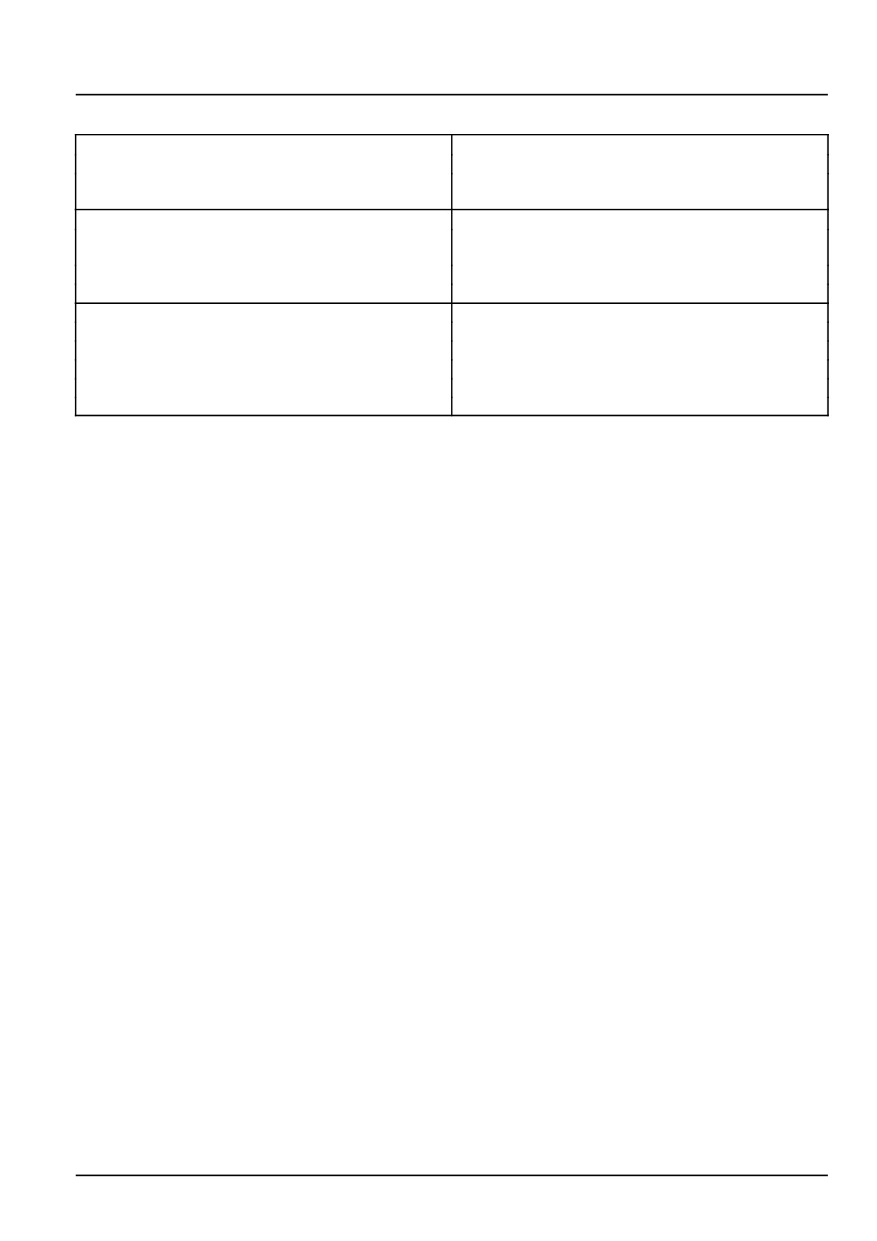
Hydraulic systems - Fixed displacement pump
Fixed displacement pump - General specification
FILTER
Type
Full-flow spin on type
Location
On suction pipe before pump intake, on the right-hand
side of the engine
PUMP
Type
Gear type (In tandem with the steering pump), drawing
oil from transmission housing
Location
On the right-hand side of the engine
Mounting
Fitted on engine timing case and driven by timing gears
Make
Rexroth (Bosch Group)
Drive
Engine timing gears
Rotation (seen from the free end of the drive shaft)
Anti-clockwise
Displacement
16 cm³ per revolution
Max. rotational speed
3300 RPM
Flow at 1500 RPM & 210 bar
21.12 L/min
35.3 [35.104] / 3
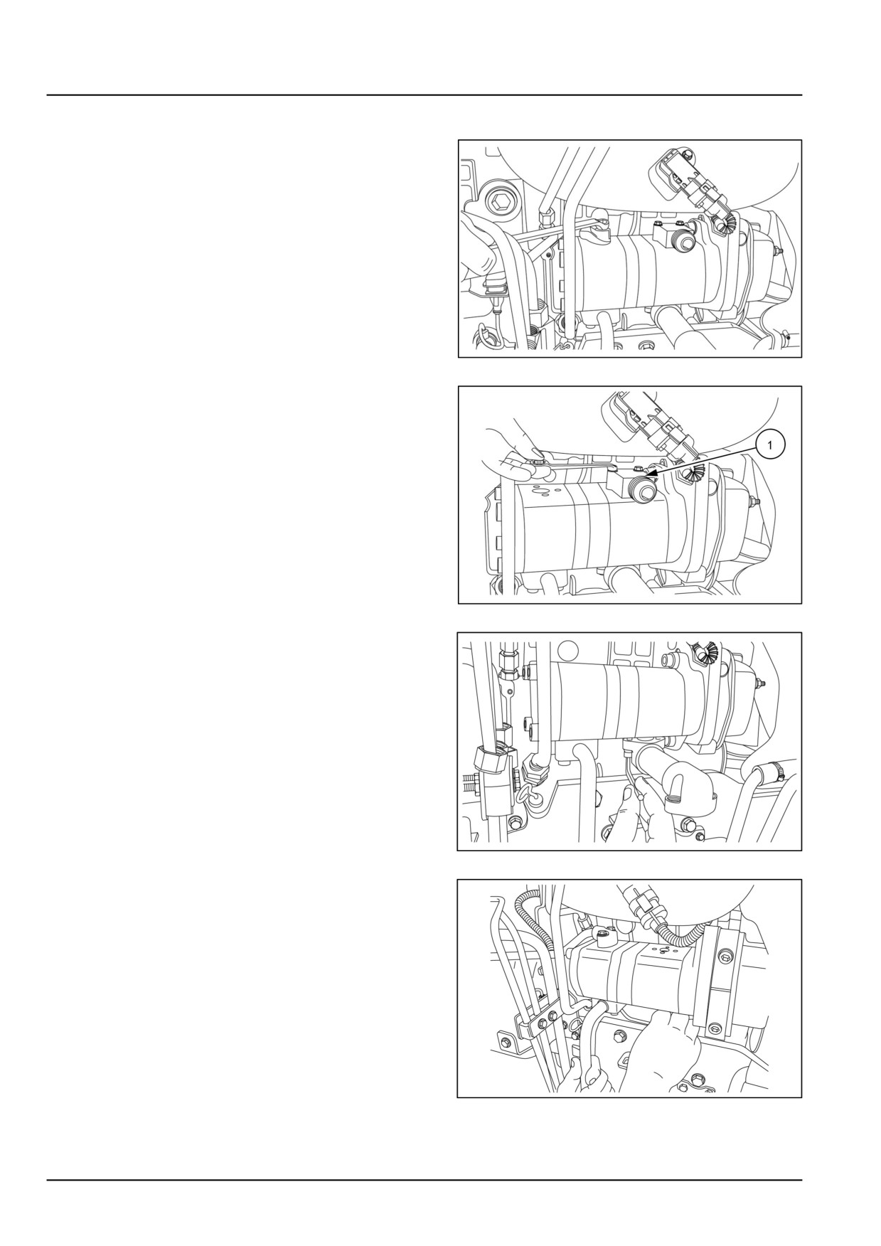
Hydraulic systems - Fixed displacement pump
Fixed displacement pump - Remove
1. Disconnect the power steering pipes on the hydraulic
hump.
GNIL14TR00729AA
1
2. Disconnect the hydraulic delivery pipe on the pump and
remove the connector (1).
GNIL14TR00730AA
2
3. Remove the hydraulic filter and connector between hy-
draulic filter and pump.
GNIL14TR00731AA
3
4. Remove the power steering suction pipe.
GNIL14TR00732AA
4
35.3 [35.104] / 4
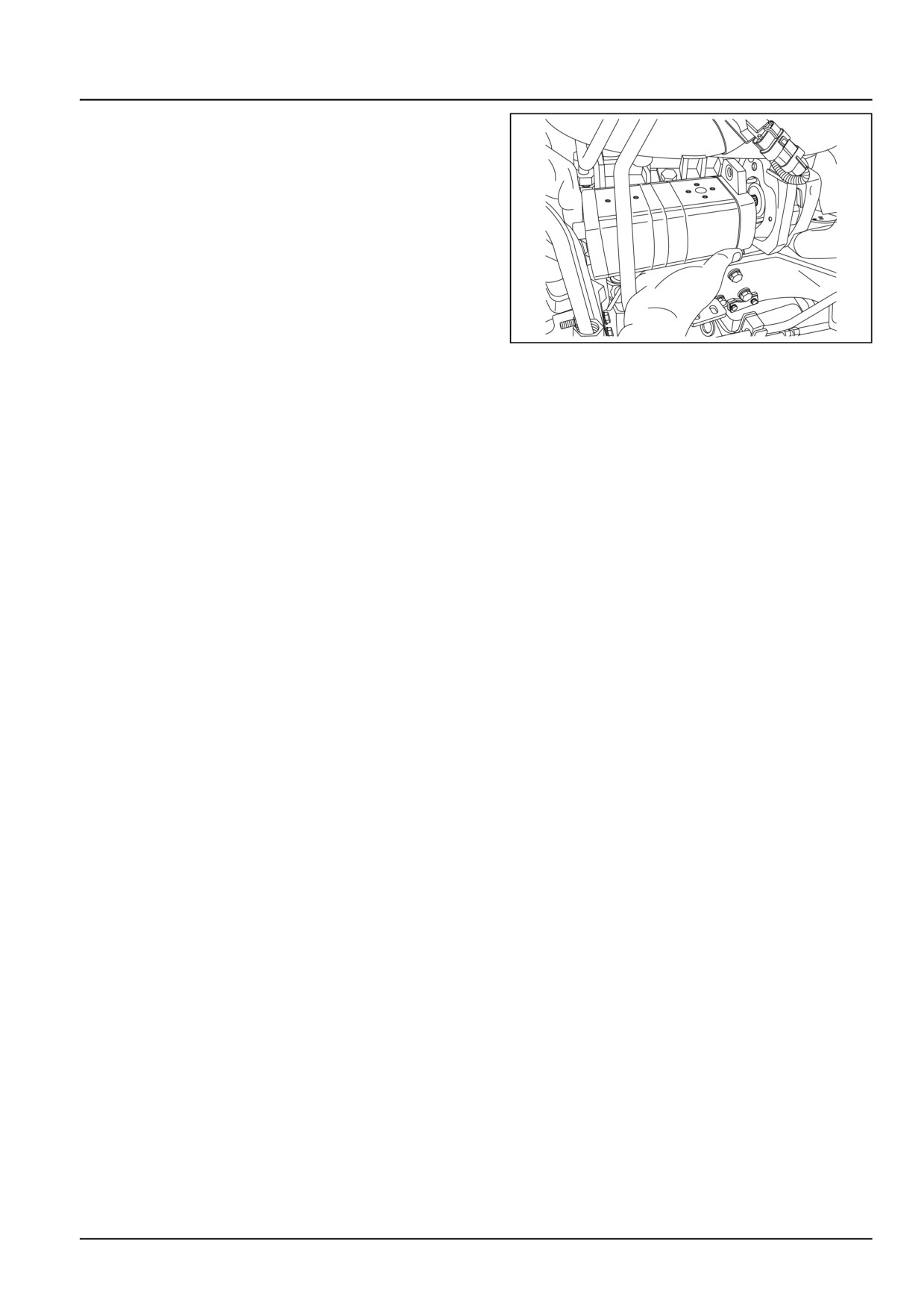
Hydraulic systems - Fixed displacement pump
5. Loosen the allen screws and remove the hydraulic
pump.
GNIL14TR00733AA
5
35.3 [35.104] / 5
Hydraulic systems - Fixed displacement pump
Fixed displacement pump - Install
For installation, follow the removal process in reverse
order.
35.3 [35.104] / 6
Index
Hydraulic systems - 35
Fixed displacement pump - 104
Fixed displacement pump - General specification
3
Fixed displacement pump - Install
6
Fixed displacement pump - Remove
4
35.3 [35.104] / 7
35.3 [35.104] / 8
Hydraulic systems - 35
Remote control valves - 204
Workmaster™ 50
Workmaster™ 60
Workmaster™ 70
35.4 [35.204] / 1
Contents
Hydraulic systems - 35
Remote control valves - 204
SERVICE
Remote control valve
Remove
3
Remove
5
Install
7
Mid-mount remote control valve
Remove
8
Install
10
35.4 [35.204] / 2
Hydraulic systems - Remote control valves
Remote control valve - Remove
WARNING
Escaping fluid!
Lower the three-point hitch to the ground and relieve all pressure from the hydraulic system before
installing the kit.
Failure to comply could result in death or serious injury.
W1114A
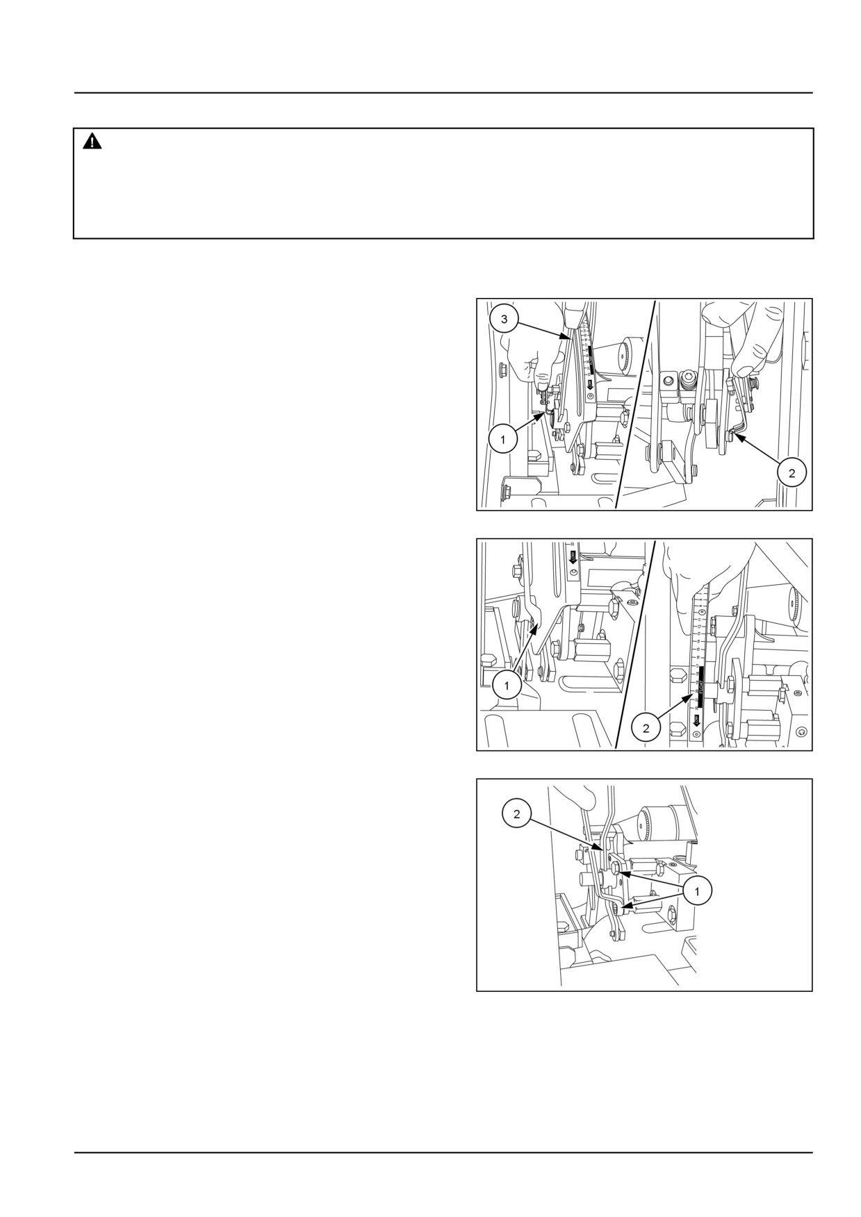
1. Loosen the set screw and remove the remote control
valve lever.
2. Remove the two circlip (1) and (2) from position control
lever. Remove the position control lever (3).
GNIL14TR00646AA
1
3. Loosen the two bolts (1) and remove the quadrant (2).
GNIL14TR00647AA
2
4. Loosen the bolts (1) and remove the draft control lever
(2).
GNIL14TR00648AA
3
35.4 [35.204] / 3
Hydraulic systems - Remote control valves
5.
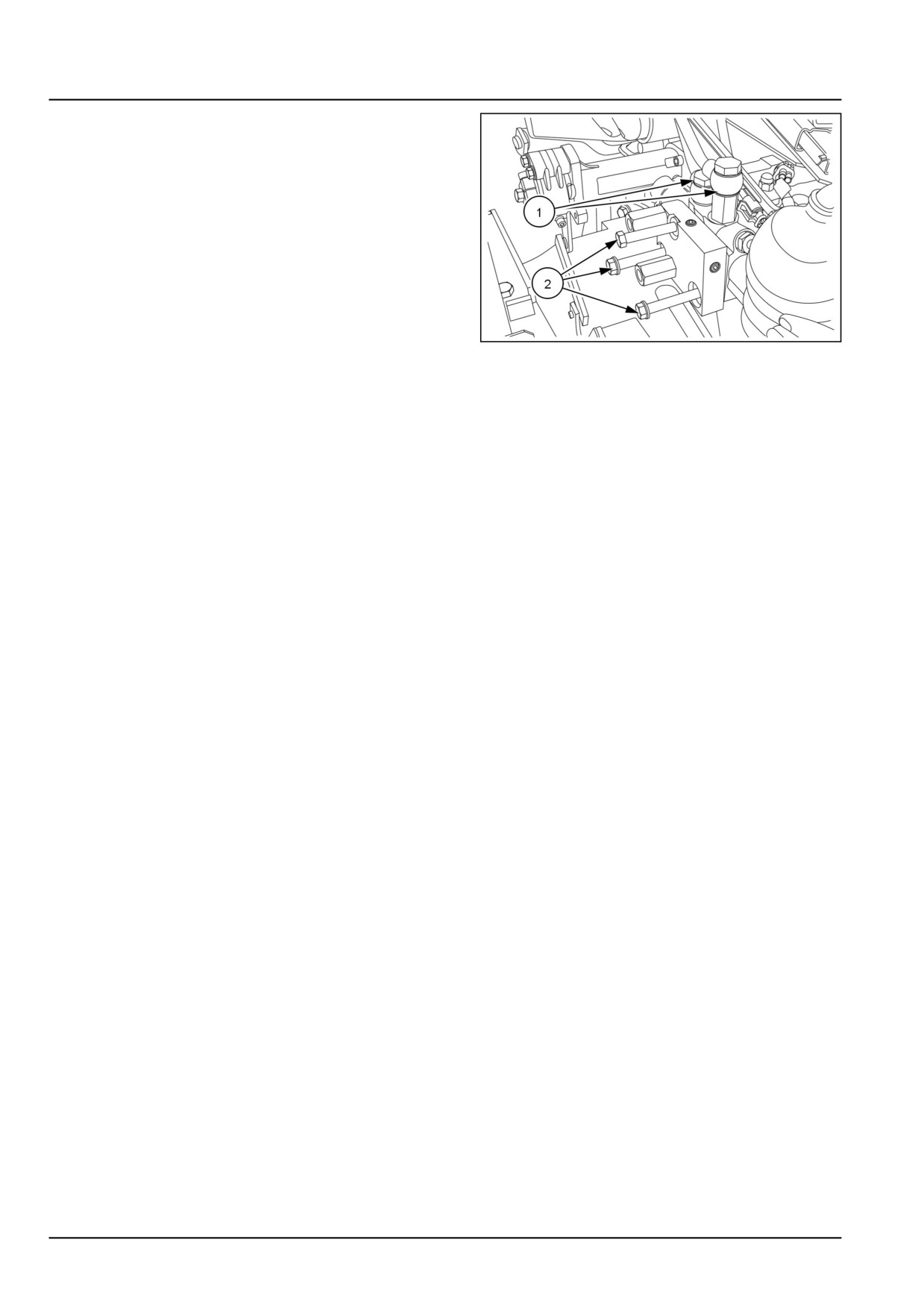
1. Remove the hydraulic pipes (1) on remote control
valve.
2. Loosen the bolts (2) and remove the plate.
3. Remove the remote control valve.
GNIL14TR00649AA
4
35.4 [35.204] / 4
Hydraulic systems - Remote control valves
Remote control valve - Remove
WARNING
Escaping fluid!
Lower the three-point hitch to the ground and relieve all pressure from the hydraulic system before
installing the kit.
Failure to comply could result in death or serious injury.
W1114A
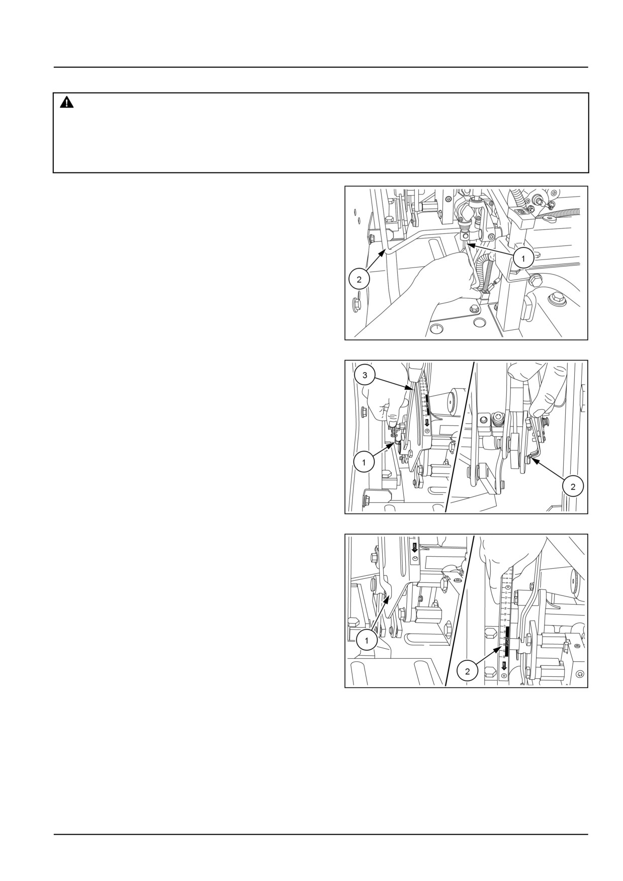
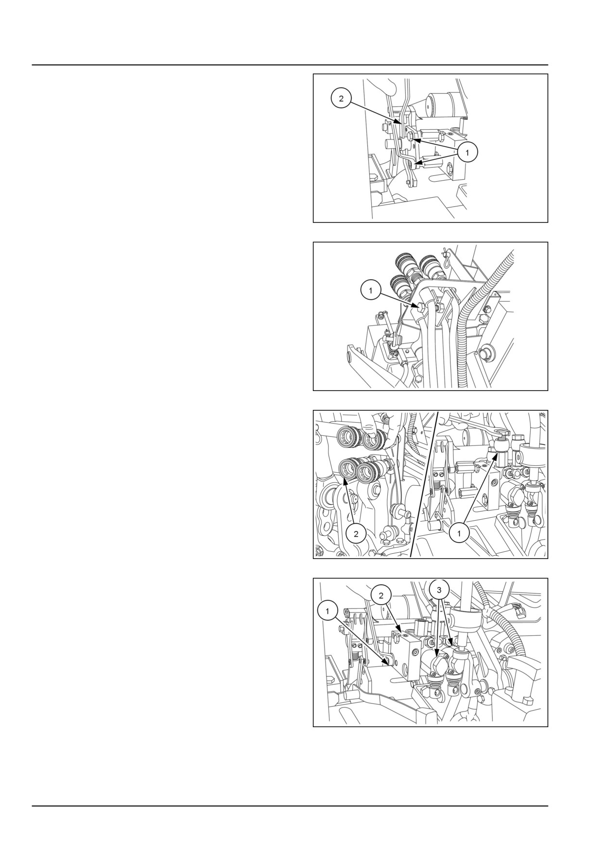
1.
1. Loosen the set screw (1). Remove the remote con-
trol valve lever (2).
2. Similarly remove the another remote control valve
lever.
GNIL14TR00659AA
1
2. Remove the two circlip (1) and (2) from position control
lever. Remove the position control lever (3).
GNIL14TR00646AA
2
3. Loosen the two bolts (1) and remove the quadrant (2).
GNIL14TR00647AA
3
35.4 [35.204] / 5
Hydraulic systems - Remote control valves
4. Loosen the bolts (1) and remove the draft control lever
(2).
GNIL14TR00648AA
4
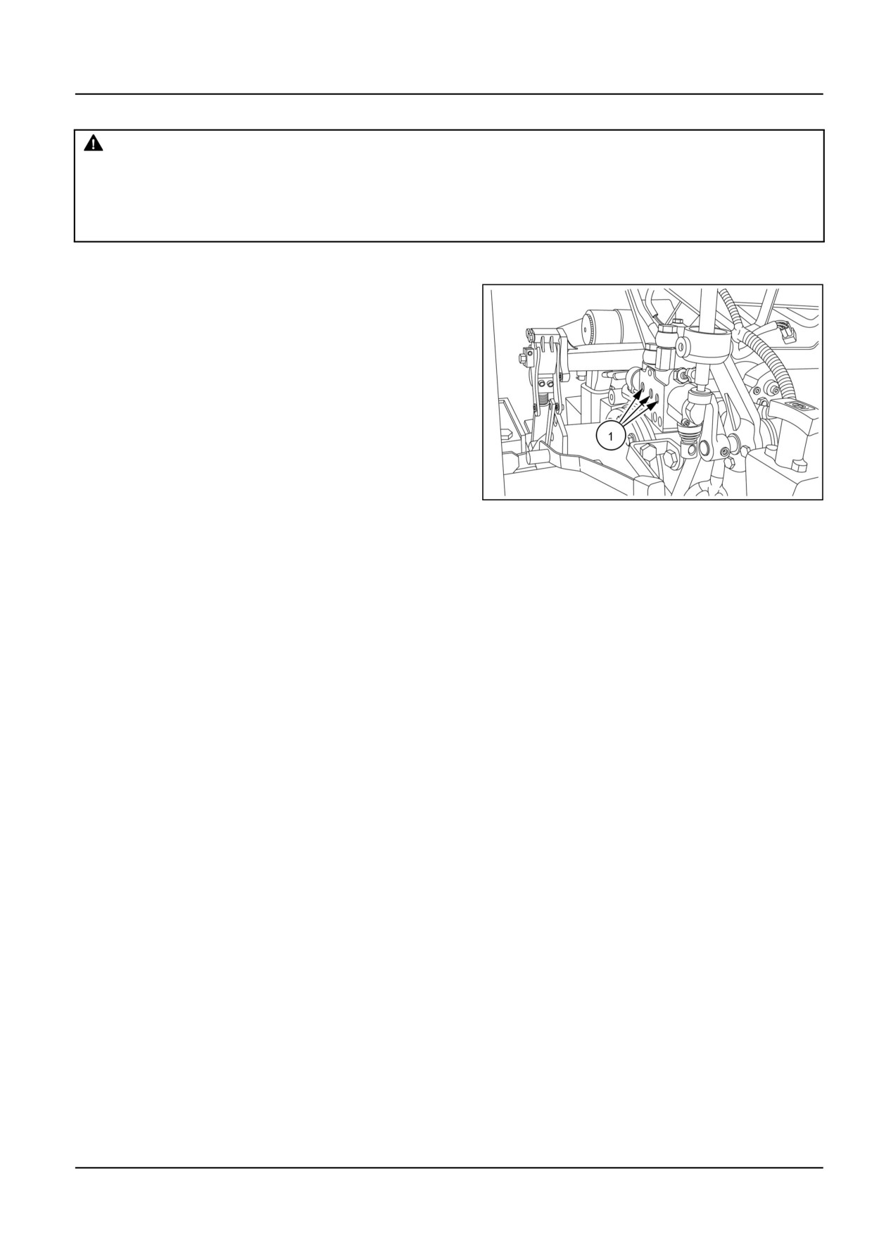
5. Loosen the bolt (1).
GNIL14TR00658AA
5
6. Loosen the bolts (1). Remove the hoses (2).
GNIL14TR00657AA
6
7.
1. Loosen the bolts (1).
2. Remove the plate (2).
3. Remove the two remote control valves (3).
GNIL14TR00652AA
7
35.4 [35.204] / 6
Hydraulic systems - Remote control valves
Remote control valve - Install
WARNING
Escaping fluid!
Lower the three-point hitch to the ground and relieve all pressure from the hydraulic system before
installing the kit.
Failure to comply could result in death or serious injury.
W1114A
NOTE: For installation, follow the removal process in reverse order.
Lubricate the seal rings (1) lightly with petroleum jelly.
This will help to hold rings in position during installation.
GNIL14TR00650AA
1
35.4 [35.204] / 7
Hydraulic systems - Remote control valves
Mid-mount remote control valve - Remove
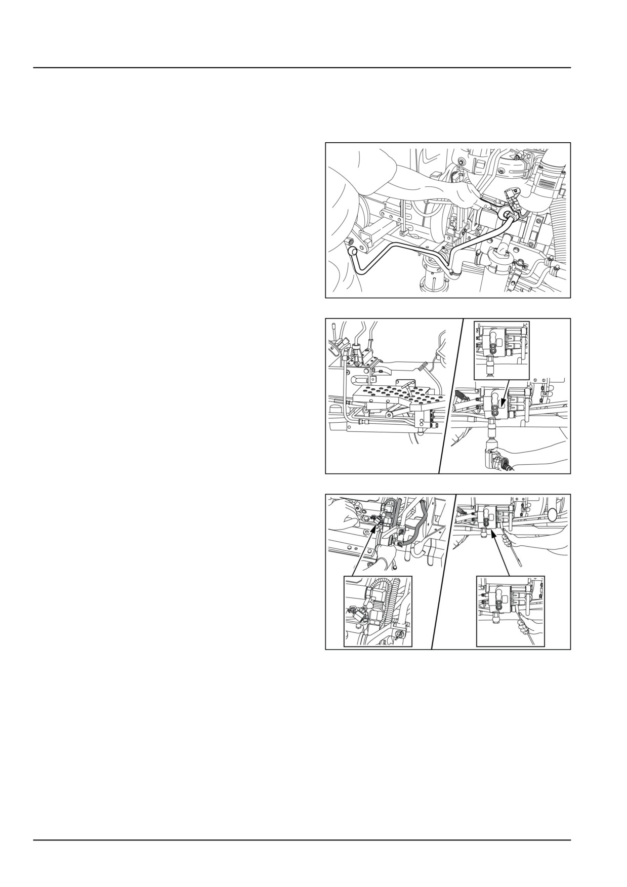
1. Disconnect the two joystick cable from the mid-mount
valve. See Joystick and Electric Hydraulic (EH) con-
trol - Remove (55.512).
2. Disconnect the hydraulic delivery pipe between hy-
draulic pump and mid-mount valve.
GNIL14TR00783AA
1
3. Disconnect the hydraulic delivery pipe between mid-
mount valve and main control valve.
GNIL14TR00843AA
2
4. Disconnect the hydraulic line between the mid-mount
valve and hydraulic lift body.
GNIL14TR00842AA
3
35.4 [35.204] / 8
Hydraulic systems - Remote control valves
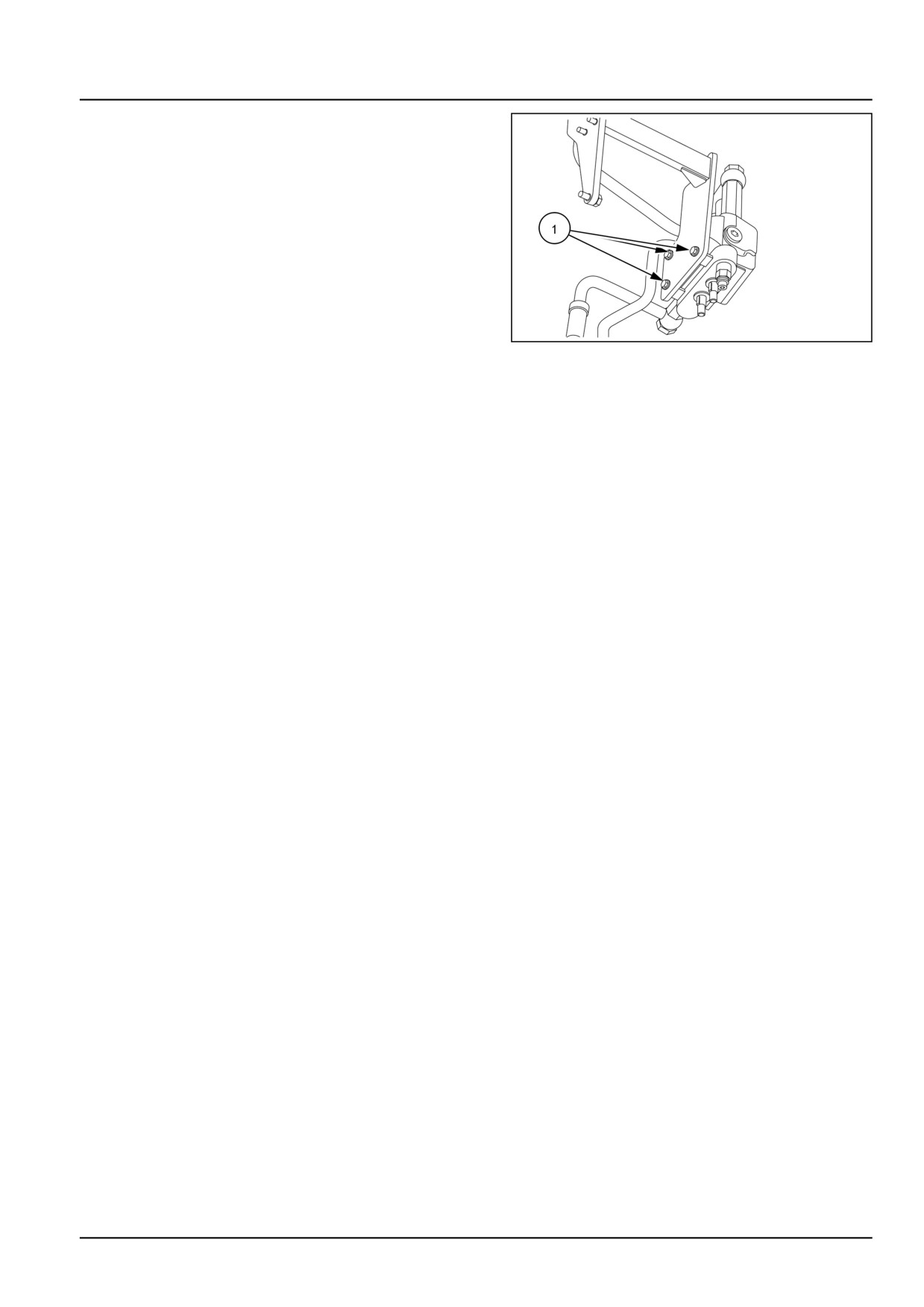
5. Loosen the bolts (1) and remove the mid-mount valve
from the mounting bracket.
GNIL14TR00844AA
4
35.4 [35.204] / 9
Hydraulic systems - Remote control valves
Mid-mount remote control valve - Install
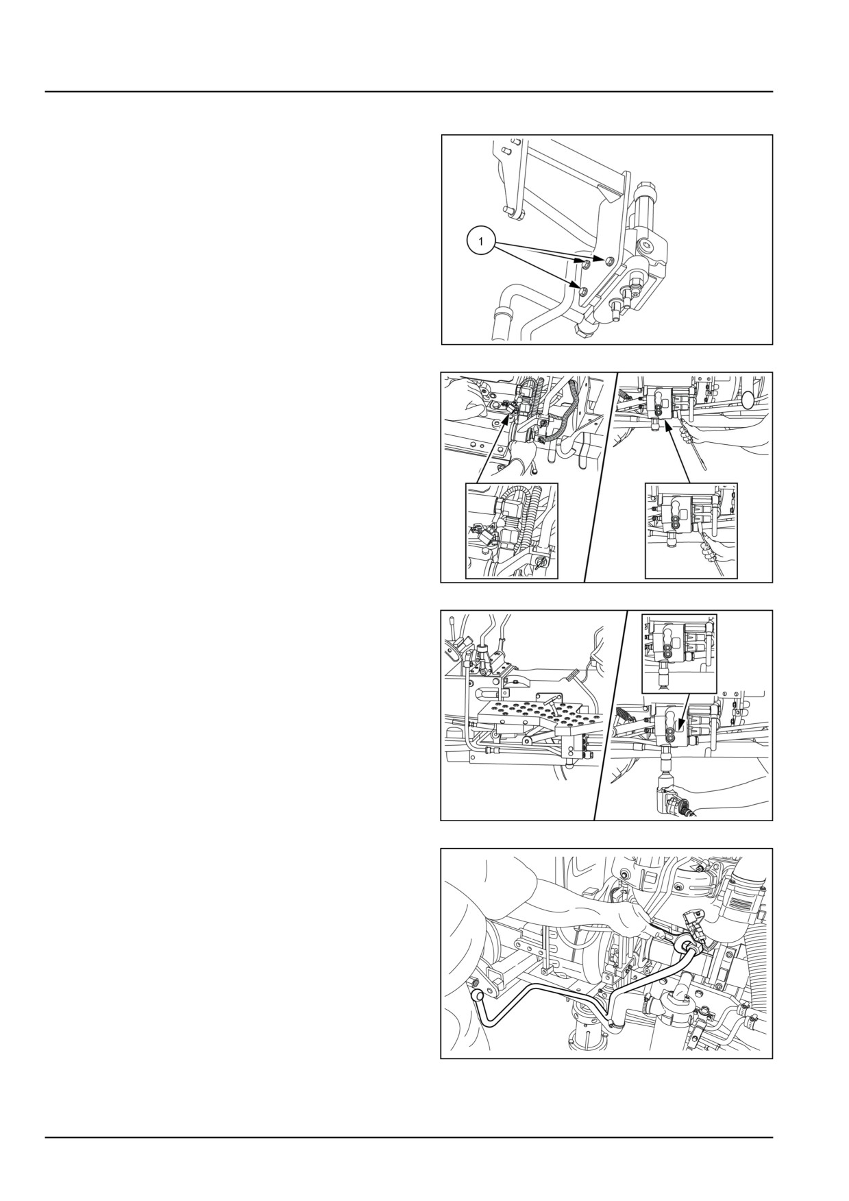
1. Install the mid-mount valve on the mounting bracket
and tighten the bolts (1).
GNIL14TR00844AA
1
2. Connect the hydraulic line between the mid-mount
valve and hydraulic lift body.
GNIL14TR00842AA
2
3. Connect the hydraulic delivery pipe between
mid-mount valve and main control valve.
GNIL14TR00843AA
3
4. Connect the hydraulic delivery pipe between hydraulic
pump and mid-mount valve.
GNIL14TR00783AA
4
5. Connect the joystick cables. See Joystick and Elec-
tric Hydraulic (EH) control - Install (55.512).
35.4 [35.204] / 10
Index
Hydraulic systems - 35
Remote control valves - 204
Mid-mount remote control valve - Install
10
Mid-mount remote control valve - Remove
8
Remote control valve - Install
7
Remote control valve - Remove
3
Remote control valve - Remove
5
35.4 [35.204] / 11
35.4 [35.204] / 12
Hydraulic systems - 35
Reservoir, cooler, and filters - 300
Workmaster™ 50
Workmaster™ 60
Workmaster™ 70
35.5 [35.300] / 1
Contents
Hydraulic systems - 35
Reservoir, cooler, and filters - 300
SERVICE
Oil filters
Remove
3
Install
4
35.5 [35.300] / 2
Hydraulic systems - Reservoir, cooler, and filters
Oil filters - Remove
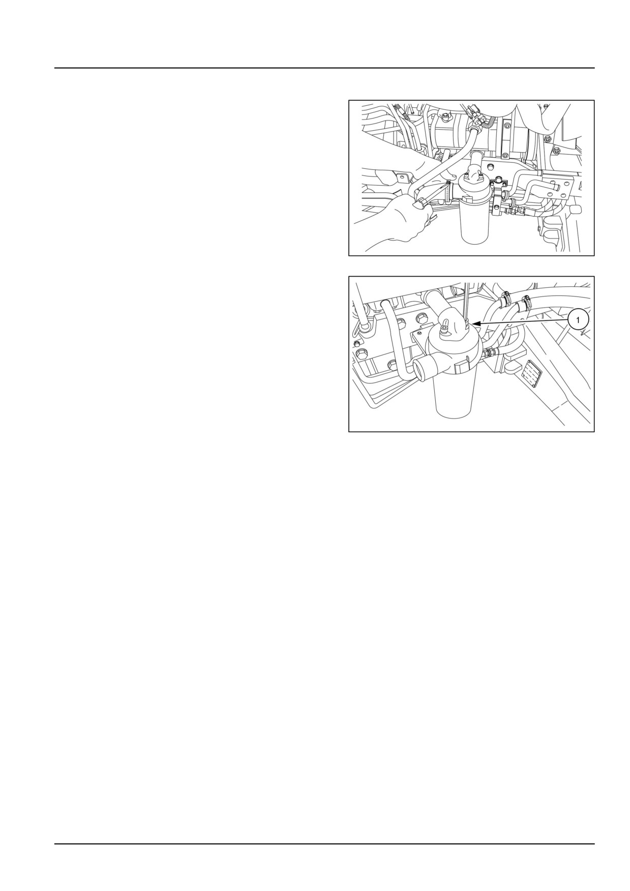
1. Loosen the clamp and remove the suction pipe from
the hydraulic filter.
GNIL14TR00725AA
1
2. Loosen the allen screws (1) and remove the hydraulic
filter.
GNIL14TR00728AA
2
35.5 [35.300] / 3
Hydraulic systems - Reservoir, cooler, and filters
Oil filters - Install
For installation, follow the reverse order of removal.
35.5 [35.300] / 4
Index
Hydraulic systems - 35
Reservoir, cooler, and filters - 300
Oil filters - Install
4
Oil filters - Remove
3
35.5 [35.300] / 5
35.5 [35.300] / 6
Hydraulic systems - 35
Hydraulic hand control - 355
Workmaster™ 50
Workmaster™ 60
Workmaster™ 70
35.6 [35.355] / 1