New Holland Tractor Workmaster 50 / Workmaster 60 / Workmaster 70 / Tier 4B (final). SERVICE MANUAL - page 10
Brakes and controls - Mechanical service brakes
Mechanical service brakes - Remove
To remove brake assembly, rear axle assembly has to
be removed from the transmission.
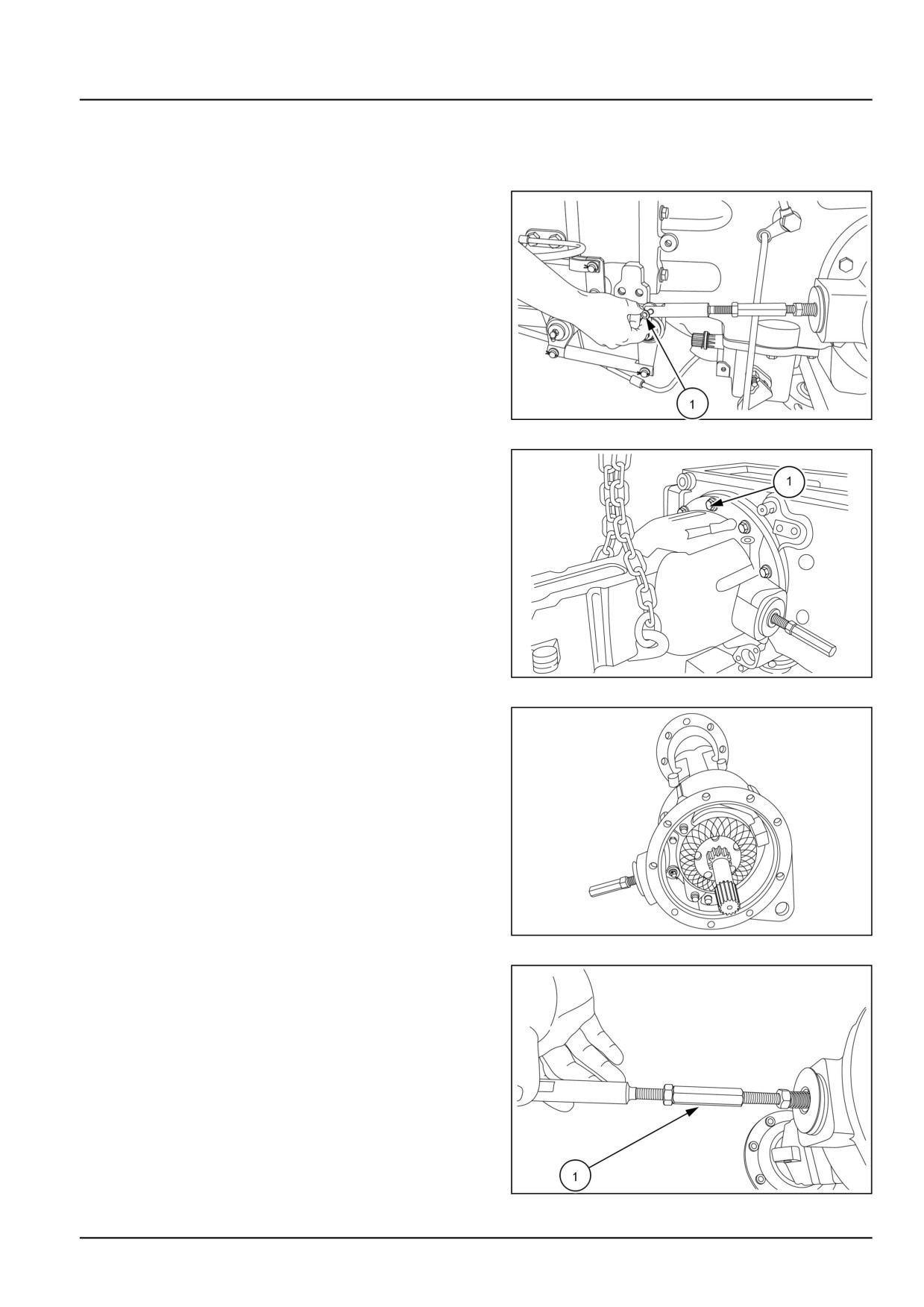
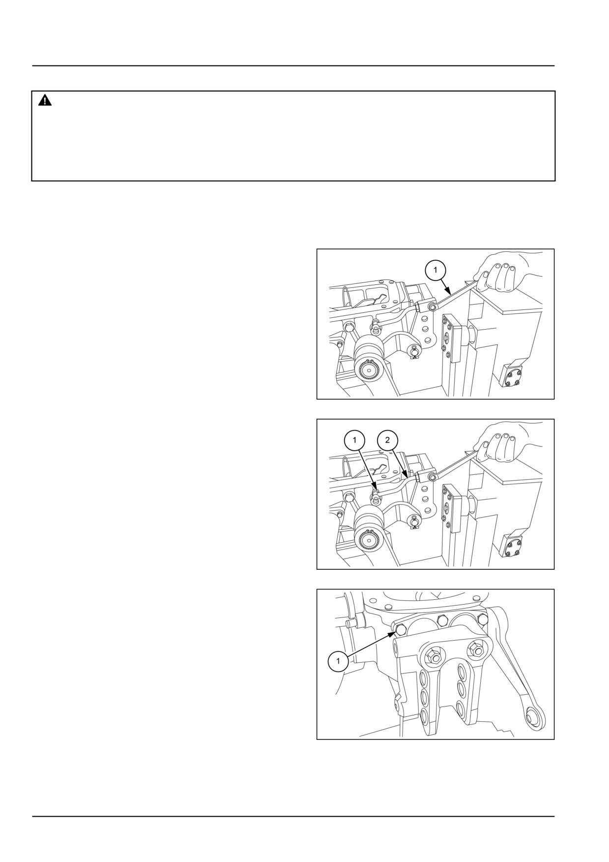
1. Remove the pin (1) and disconnect the brake linkage.
GNIL14TR00789AA
1
2. Wrap chain around final drive housing and loosen bolts
(1). Remove the final drive housing.
GNIL14TR04276AB
2
3. Place the trumpet housing assembly on plane surface.
GNIL14TR04336AA
3
4. Remove the linkage (1).
GNIL14TR00792AA
4
33.1 [33.120] / 9
Brakes and controls - Mechanical service brakes
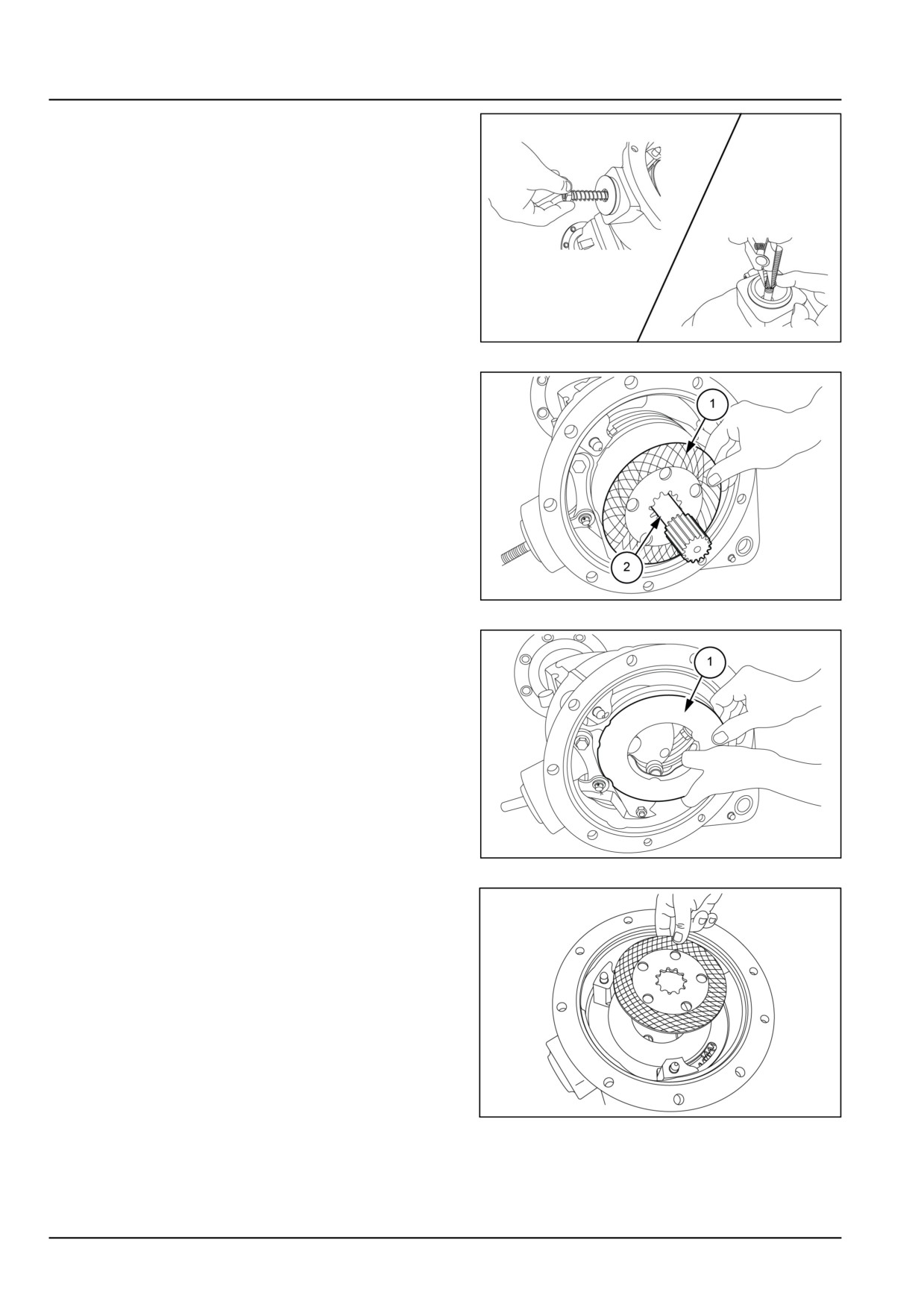
5. Remove the nut and spring. Remove the circlip.
GNIL14TR00791AA
5
6. Remove brake disc (1) and shaft (2).
GNIL14TR04277AB
6
7. Remove the brake actuator assembly (1).
GNIL14TR04278AB
7
8. Remove second brake disc.
GNIL14TR00779AA
8
33.1 [33.120] / 10
Brakes and controls - Mechanical service brakes
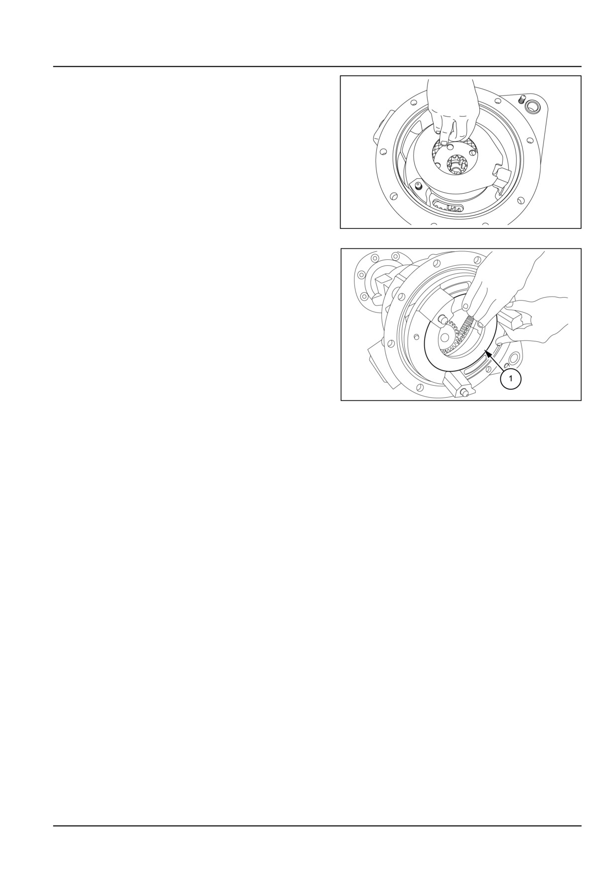
9. Remove intermediate plate and third brake disc.
GNIL14TR00780AA
9
10. Remove dual brake support (1) as shown.
GNIL14TR04279AB
10
33.1 [33.120] / 11
Brakes and controls - Mechanical service brakes
Mechanical service brakes - Inspect
1. Inspect the brake flange friction face for wear and dam-
age, replace if necessary.
2. Inspect the inner and outer brake discs, if badly scored,
worn or cracked, replace.
NOTE: Brake discs’ thickness should be minimum
4.300 mm (0.169 in).
33.1 [33.120] / 12
Brakes and controls - Mechanical service brakes
Mechanical service brakes - Install
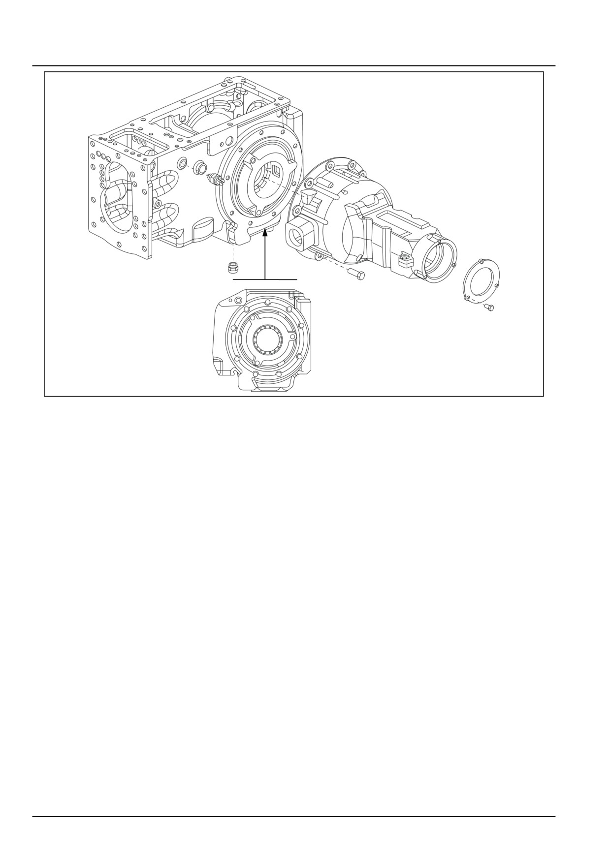
NOTE: Always use suitable tools to align holes. Do not use hand or fingers.
1. Reinstall the brake assembly and rear axle housing to
the differential housing taking the following into consid-
eration.
• Reassembly follows the disassembly procedure in
reverse, form step 5 back to step 1.
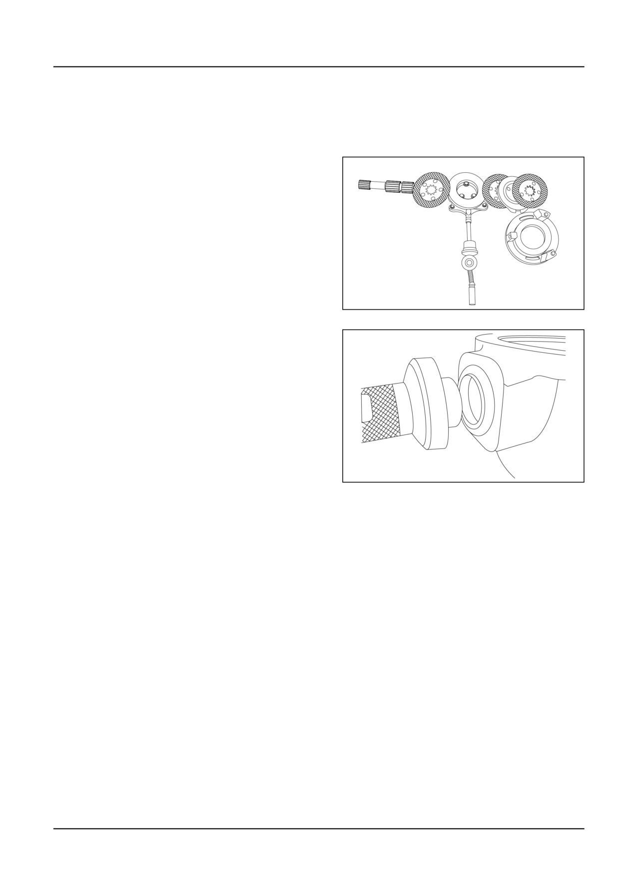
• Refer to figure to orient the different parts.
• Use special tool number 84261390 to fit the brake
rubber boot in the brake linkage groove and
brake rubber brake boot with special tool number
84261391 in trumpet housing.
GNIL14TR04340AA
1
• Before reinstalling the rear axle housing, thoroughly
clean and degrease mating surfaces and apply a
bead of liquid gasket of approx. 2.000 mm (0.079 in)
of diameter.
• Check seals for wear and damage and replace if
necessary.
• Tighten to correct torques.
After brake assembly fitted in differential housing, check
brake discs for free movement between brake discs.
GNIL14TR04341AA
2
33.1 [33.120] / 13
Brakes and controls - Mechanical service brakes
GNIL14TR04342FA
3
33.1 [33.120] / 14
Brakes and controls - Mechanical service brakes
Brake control pedals and shafts - Remove
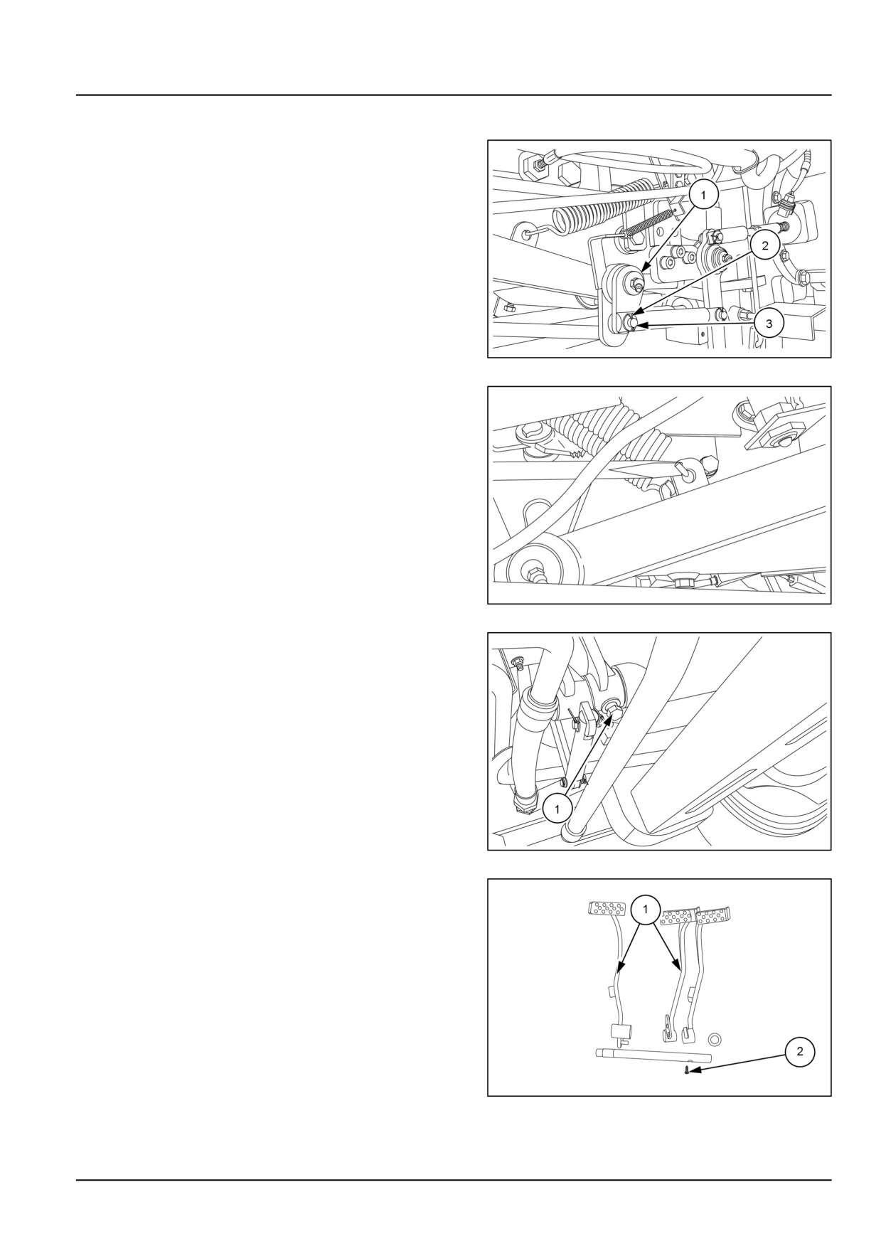
1. Remove circlip (1). Unlock the clip (2) and remove pin
(3) from the left-hand and right-hand side brake link-
ages.
GNIL14TR00766AA
1
2. Remove the brake pedal springs. Remove the clutch
pedal springs.
GNIL14TR00782AA
2
3. Remove the conical screw (1) that locks the brake
shaft.
GNIL14TR00812AA
3
4. Slide out both left-hand and right-hand side brake ped-
als (1) from brake shaft (2).
GNIL14TR04332AB
4
33.1 [33.120] / 15
Brakes and controls - Mechanical service brakes
Parking brake linkage removal
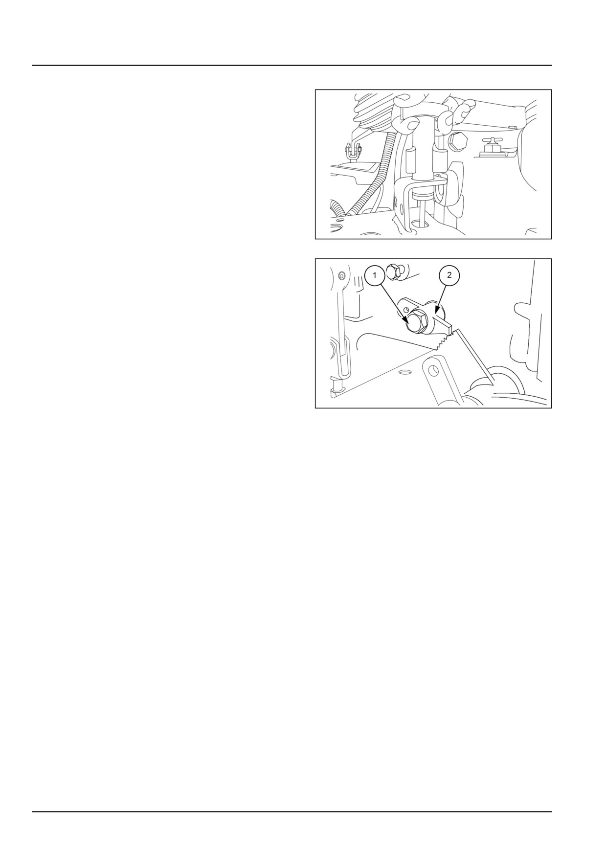
5. Remove split pin from hand brake linkage.
6. Pull out hand brake lever along with linkage rod from
the linkage assembly.
GNIL14TR04333AA
5
7. Loosen the bolt (1) and remove hand brake pawl (2).
GNIL14TR04334AB
6
33.1 [33.120] / 16
Brakes and controls - Mechanical service brakes
Brake control pedals and shafts - Adjust
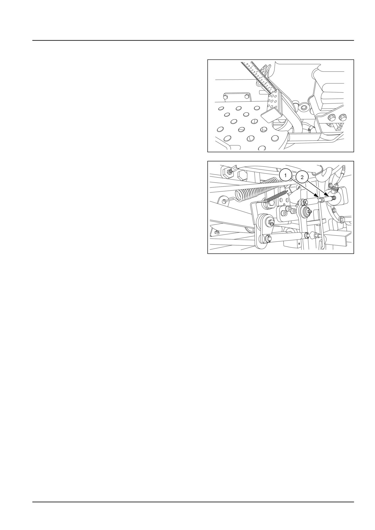
1. Measure free play of the brake pedals as shown in 1
and should be 50.00 - 55.00 mm (1.97 - 2.17 in). With
the brake pedals locked together, the tractor should
stop in a straight line when brakes are applied.
2. Adjustment is made to the brake pull rods beneath the
tractor. Block the wheels, front and rear, unlock the
brake pedals and release the parking brake lever. Re-
lease locking clamp, loosen locknut (1) and rotate the
yoke (2) clockwise to reduce the play and anti-clock-
wise to increase the play figure 2.
3. Repeat the same procedure for the left brake pull rod.
4. Lock the brake pedals together and road test to ensure
GNIL14TR04343AA
1
that the brakes are balanced and will stop the tractor
in a straight line. Any further adjustment necessary to
balance the brakes should be carried out on the right
brake.
GNIL14TR00766AA
2
33.1 [33.120] / 17
Brakes and controls - Mechanical service brakes
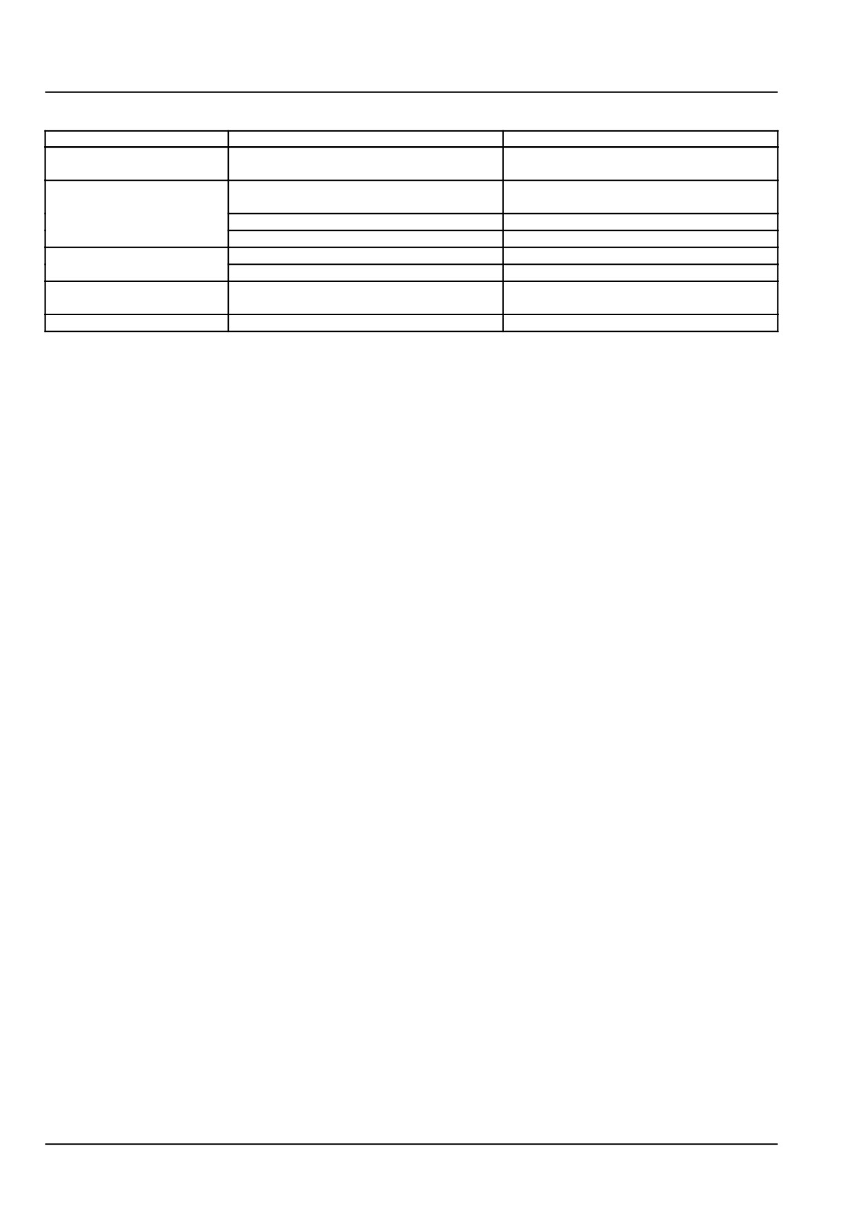
Mechanical service brakes - Troubleshooting
Problem
Possible Cause
Correction
Brake actuate only when
Incorrect Pedal adjustment
Check and adjust
pedal is depressed fully
Tractor pulls to one side
Brakes not equally adjusted
Adjust
when brakes applied
Wrong tire pressure
Inflate tires to correct pressure
Wrong liners on one side
Replace discs
Brakes noisy
Oil contamination
Check and change with recommended oil.
Wrong brake disc
Replace brake discs.
Brakes remain applied
Seized brake actuating linkages
Clean and lubricate linkages
when pedals are released
Pedals are hard to operate
Seized brake actuating linkages
Clean and lubricate linkages
33.1 [33.120] / 18
Index
Brakes and controls - 33
Mechanical service brakes - 120
Brake control pedals and shafts - Adjust
17
Brake control pedals and shafts - Remove
15
Mechanical service brakes - Exploded view
6
Mechanical service brakes - General specification
3
Mechanical service brakes - Inspect
12
Mechanical service brakes - Install
13
Mechanical service brakes - Overview
7
Mechanical service brakes - Remove
9
Mechanical service brakes - Sealing
4
Mechanical service brakes - Sectional view
8
Mechanical service brakes - Special tools
3
Mechanical service brakes - Torque
3
Mechanical service brakes - Troubleshooting
18
33.1 [33.120] / 19
CNH Industrial America New Holland Site 100 Brubaker Avenue New Holland, Pennsylvania United States
17557
SERVICE - Technical Publications & Tools
PRINTED IN U.S.A.
All rights reserved. No part of the text or illustrations of this publication may be reproduced.
NEW HOLLAND policy is one of continuous improvement and the right to change prices, specification or equipment
at any time without notices is reserved.
All data given in this publication is subject to production variations. Dimensions and weight are approximate only and
the illustrations do not necessarily show products in standard condition. For exact information about any particular
product, please consult your NEW HOLLAND Dealer.
EN
SERVICE MANUAL
Hydraulic systems
Workmaster™ 50
Workmaster™ 60
Workmaster™ 70
35
Contents
Hydraulic systems - 35
[35.000] Hydraulic systems
35.1
[35.100] Main lift system
35.2
[35.104] Fixed displacement pump
35.3
[35.204] Remote control valves
35.4
[35.300] Reservoir, cooler, and filters
35.5
[35.355] Hydraulic hand control
35.6
[35.359] Main control valve
35.7
35
Hydraulic systems - 35
Hydraulic systems - 000
Workmaster™ 50
Workmaster™ 60
Workmaster™ 70
35.1 [35.000] / 1
Contents
Hydraulic systems - 35
Hydraulic systems - 000
FUNCTIONAL DATA
Hydraulic systems
Overview
3
Hydraulic schema
4
Component identification
6
DIAGNOSTIC
Hydraulic systems
Troubleshooting
8
35.1 [35.000] / 2
Hydraulic systems - Hydraulic systems
Hydraulic systems - Overview
The hydraulic system on the tractor is for mechanical lift assembly to raise and lower the lift arms and thus the three
point linkage.
The high pressure hydraulic circuit is an open centre load sensing type.
The hydraulic lift is connected to the hydraulic pump. The pump flow is continuous in the hydraulic system even when
the circuit is not being operated.
High pressure pump is directly connected on rear side of engine timing gear. Oil is drawn from transmission case
through filter. The pump supplies constant oil flow according to engine speed. High pressure oil enters the distributor
valve located at the front of the lift assembly, which controls the raising and lowering of the lift.
All excess oil flow produced by the hydraulic pump is returned direct to the gear box through the control valve spool
located in the distributor.
Also located within the distributor is the lift cylinder safety valve, which protect the lift cylinder and seals from excessive
peaks of pressure during operation. For further details refer to the “hydraulic lift assembly”.
35.1 [35.000] / 3
Hydraulic systems - Hydraulic systems
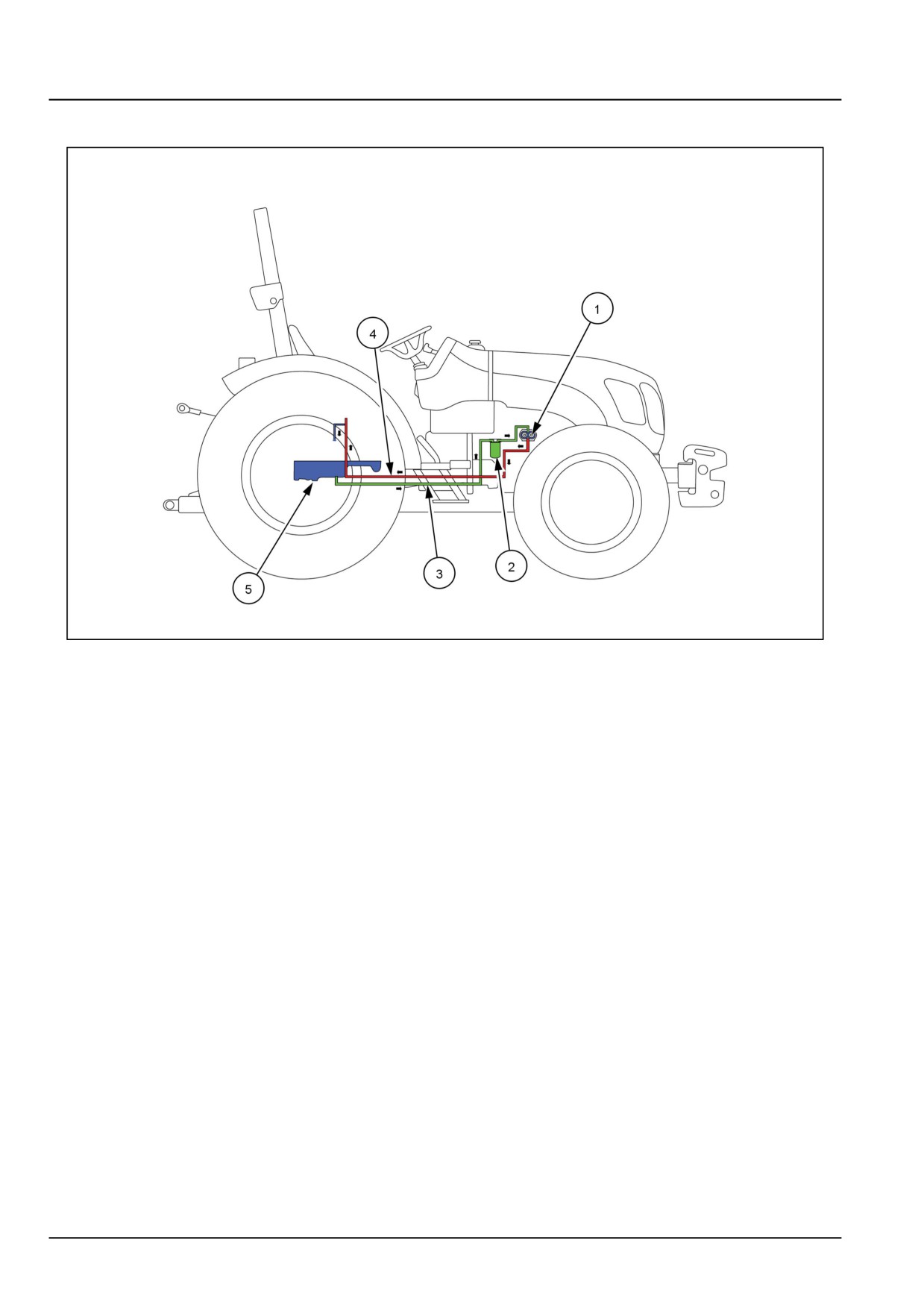
Hydraulic systems - Hydraulic schema
GNIL14TR00817GA
1
Schematic view of hydraulic system
(1) Hydraulic pump
(4) Delivery line
(2) Hydraulic filter
(5) Oil sump (transmission housing)
(3) Suction line
35.1 [35.000] / 4
Hydraulic systems - Hydraulic systems
GNIL14TR00818GA
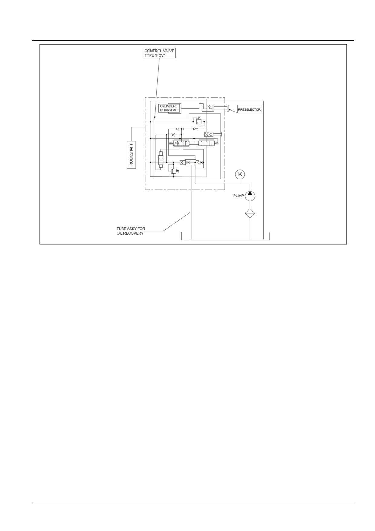
2
Hydraulic circuit diagram
35.1 [35.000] / 5
Hydraulic systems - Hydraulic systems
Hydraulic systems - Component identification
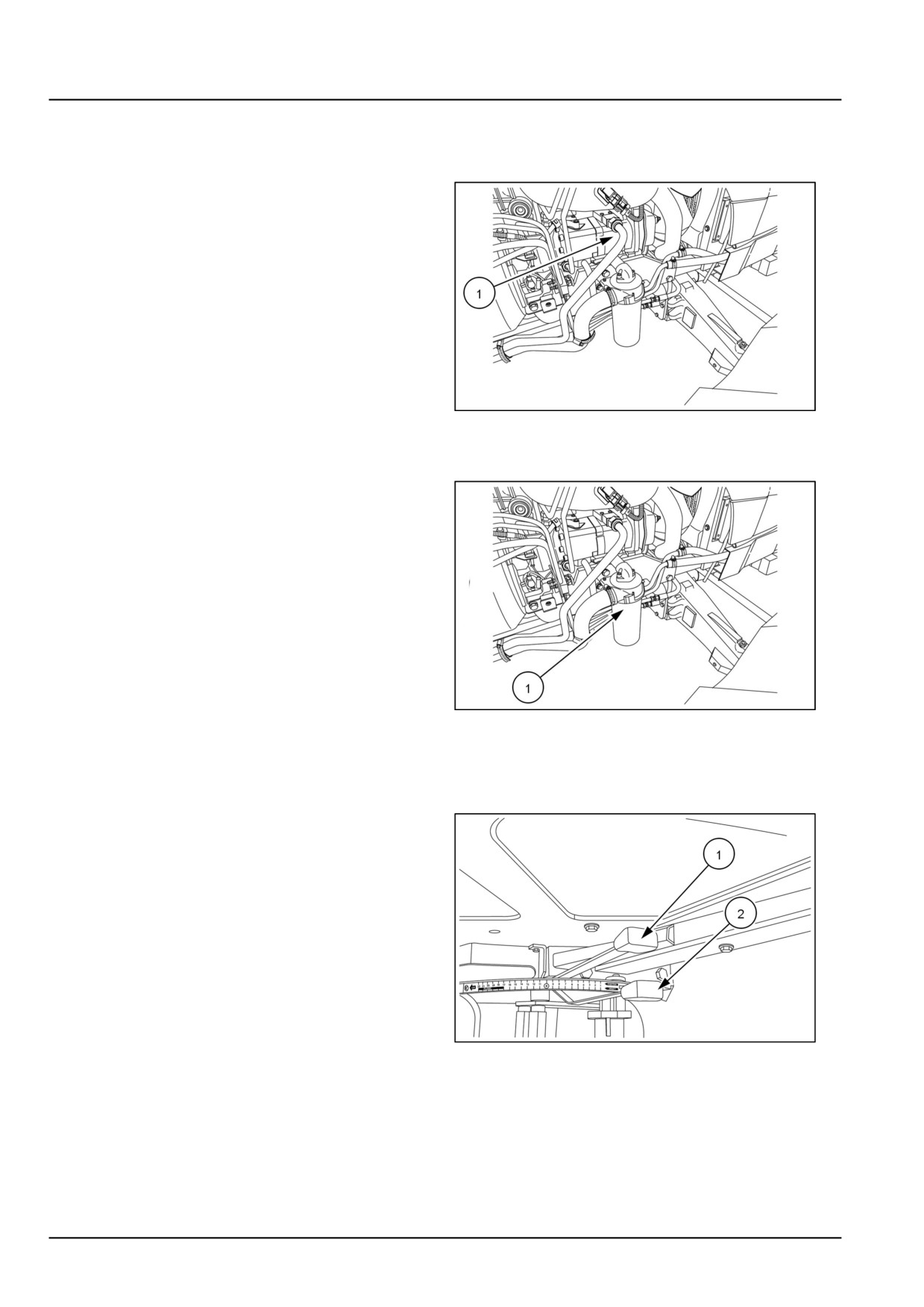
Pump
Open centre hydraulic pump assembly is of high pressure
gear pump (1).
GNIL14TR00519AA
1
Filter
Full-flow spin on type filter (1) mounted on right side of the
engine on suction pump.
GNIL14TR00519AA
2
Mechanical hydraulic lift assembly
Mounted on top of transmission housing comprising of following components:
• Position control lever (1)
• Draft control lever (2)
GNIL14TR00580AA
3
35.1 [35.000] / 6
Hydraulic systems - Hydraulic systems
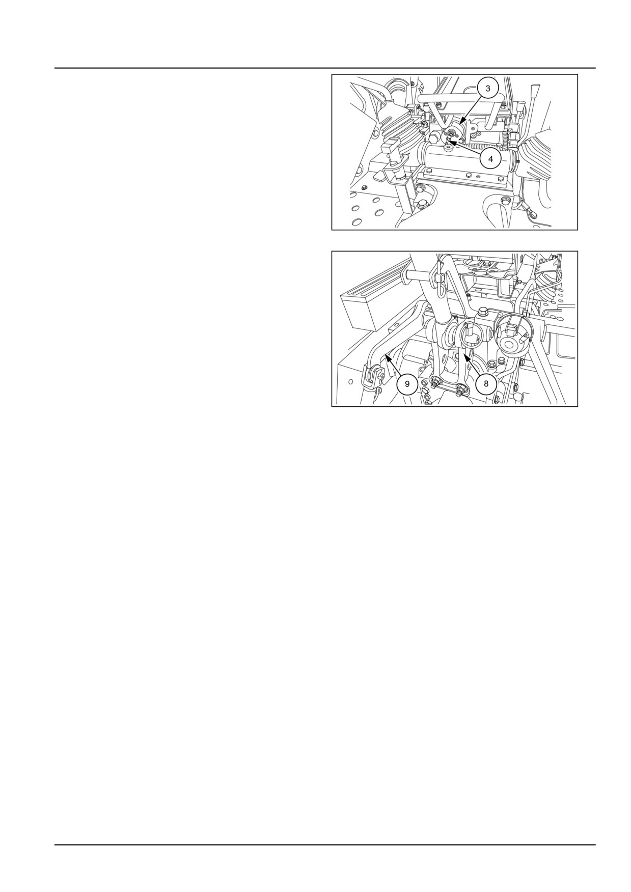
• Distributor (3)
• Response control valve (4)
GNIL14TR00804AA
4
• Draft sensing unit (8)
• Lift arms (9)
• Internal linkages and cylinder assembly
GNIL14TR04568AB
5
35.1 [35.000] / 7
Hydraulic systems - Hydraulic systems
Hydraulic systems - Troubleshooting
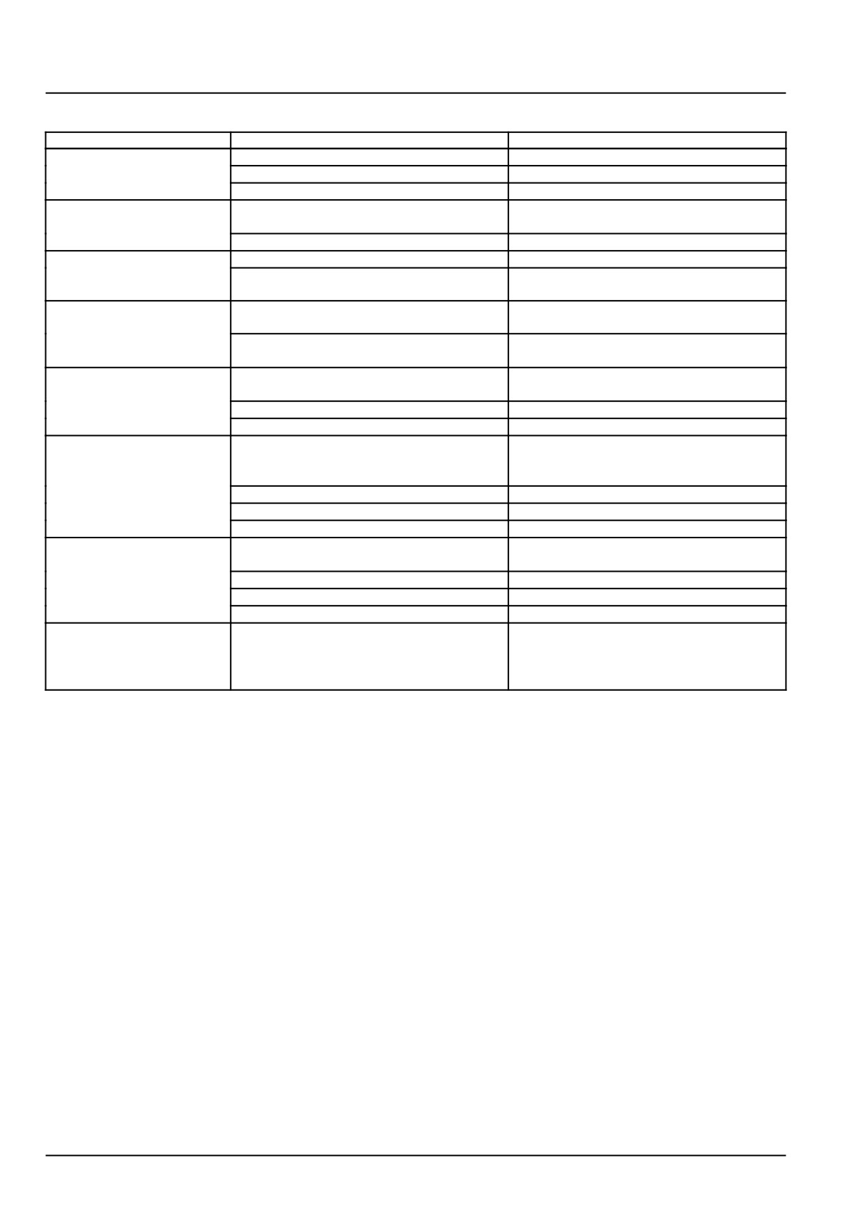
Problem
Possible Cause
Correction
Lift arms lift jerky
Hydraulic oil level low
Add hydraulic oil to correct level
Suction Filter is clogged
Replace oil filter
Pump has an air suction leak
Check all inlet pipe connections
Lift arms do not lift
Inner control valve spool not shifting to
Remove control valve and clean spool
open position
Regulator valve not shifting
Remove and clean regulator valve
Lift arms do not lower
Discharge valve blocked
Remove discharge valve and clean
Lowering response valve closed
Open lowering response valve by turning
counterclockwise
Lift arms do not lower full
Incorrect adjustment of the position control
Adjust position control lever
travel
lever
Control valve sensitivity adjustment not ad-
Adjust control valve sensitivity
justed correctly
Low lift capacity
Damaged control valve outer diameter
Replace O-rings as necessary
O-rings
Relief valve not adjusted correctly
Adjust relief valve to specification
Worn lift cylinder piston seal
Replace damaged seal
Lift arms cycle up and
Lift cylinder piston seal damaged
Replace piston seal
down with load applied
with engine running
Discharge valve not adjusted correctly
Adjust sensitivity of control valve
Lift check valve not seating properly
Inspect lift check valve for contamination
Safety valve not seating properly
Inspect safety valve for contamination
Lift arms leak down when
Lift cylinder piston seal damaged
Replace piston seal
engine is not running
Discharge valve not adjusted correctly
Adjust sensitivity of control valve
Lift check valve not seating properly
Inspect lift check valve for contamination
Safety valve not seating properly
Inspect safety valve for contamination
When lift arms are at
Position control lever maximum height po-
Adjust position control lever maximum po-
maximum lift height, with
sition not adjusted correctly
sition setting
the engine running, the lift
arms cycle up and down
35.1 [35.000] / 8
Index
Hydraulic systems - 35
Hydraulic systems - 000
Hydraulic systems - Component identification
6
Hydraulic systems - Hydraulic schema
4
Hydraulic systems - Overview
3
Hydraulic systems - Troubleshooting
8
35.1 [35.000] / 9
Hydraulic systems - 35
Main lift system - 100
Workmaster™ 50
Workmaster™ 60
Workmaster™ 70
35.2 [35.100] / 1
Contents
Hydraulic systems - 35
Main lift system - 100
TECHNICAL DATA
Main lift system
General specification
3
Torque
3
Sealing
4
Special tools
5
FUNCTIONAL DATA
Main lift system
Dynamic description
6
SERVICE
Main lift system
Remove
11
Install
13
Disassemble
14
Assemble
21
Adjust
22
Inspect
27
DIAGNOSTIC
Main lift system
Troubleshooting
29
35.2 [35.100] / 2
Hydraulic systems - Main lift system
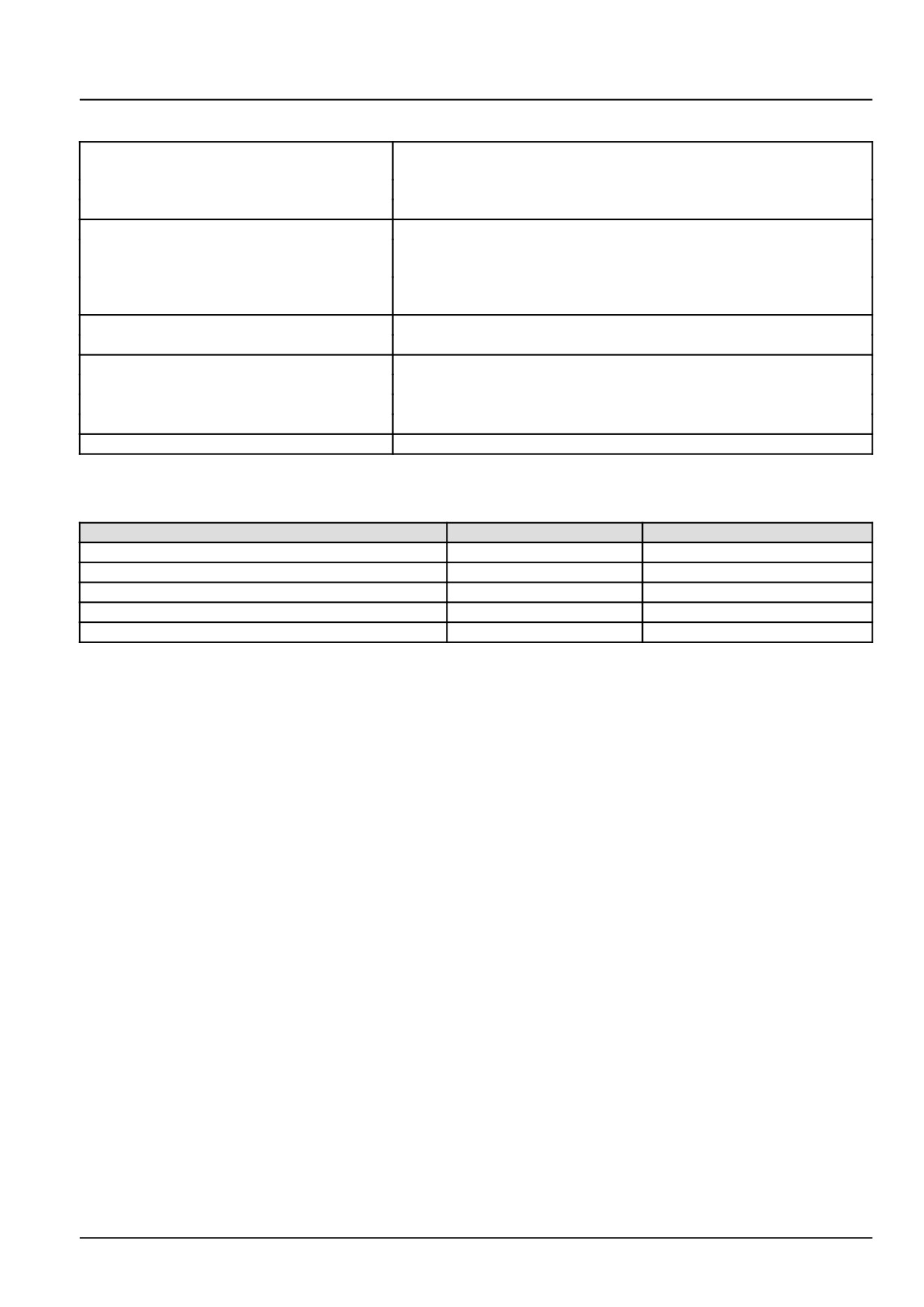
Main lift system - General specification
With separate position or draft control, Mixed position/draft control
Type
plus draft sensitivity and float control
Control
Through two independent levers external knob on control valve
Response/drop rate adjustment
Through external knob on control valve
Single-acting cylinder
85.0 mm (3.3 in) x 88.0 mm (3.5 in) for 1100.0 kg (2425.1 lb)
• Bore and stroke
90.0 mm (3.5 in) x 117.0 mm (4.6 in) for 1500.0 kg (3306.9 lb)
500 cm³ for 1100.0 kg (2425.1 lb)
• Displacement
745 cm³ for 1500.0 kg (3306.9 lb)
Pressure regulating valve setting
190 bar (2755 psi)
Cylinder safety valve opening pressure
205.0 bar (2972.5 psi)
Implement attachment
Type
3-Point hitch
Category
I & II
Draft control
Through top link
Maximum lifting capacity at hitch point
1100 kg (2425 lb) and 1500.0 kg (3306.9 lb) for heavy duty
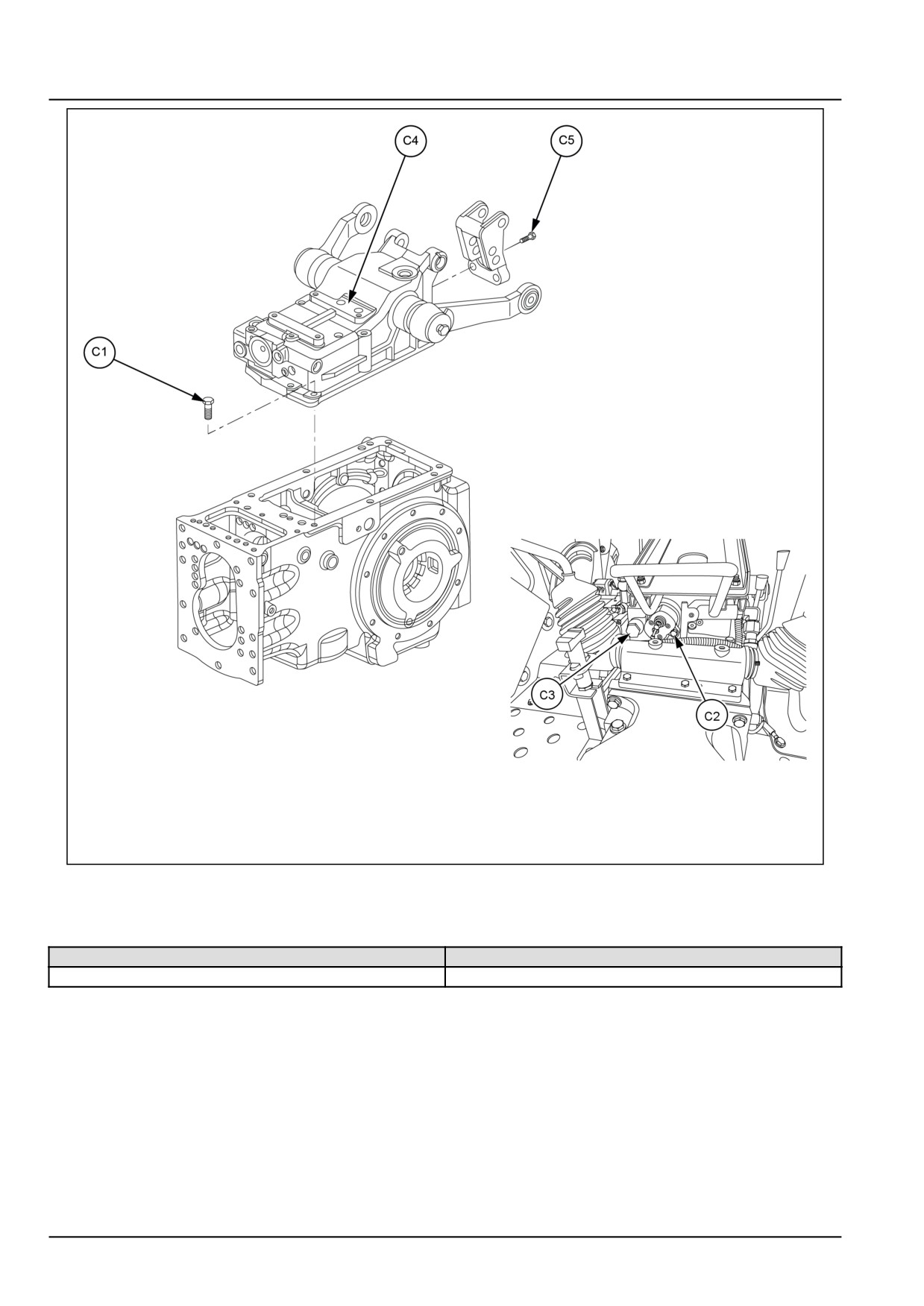
Main lift system - Torque
Description
Thread size
Torque
Bolts, lift to housing (C1)
M10 x 1.25 and M12 x 1.25
23.6 - 42.0 kgf (52.0 - 92.6 lbf)
Bolts, distributor to lift housing (C2)
M8 x 1.25
3.0 kgf (6.6 lbf)
Banjo bolts, delivery pipe to distributor (C3)
M22 x 1.25
7.5 kgf (16.5 lbf)
Hydraulic cylinder to lift housing (C4)
M12 and M14 x 1.25
7.5 kgf (16.5 lbf)
Bolts, top link support (C5)
M8 x 1.25
5.0 kgf (11.0 lbf)
35.2 [35.100] / 3
Hydraulic systems - Main lift system
GNIL14TR00819GA
1
Main lift system - Sealing
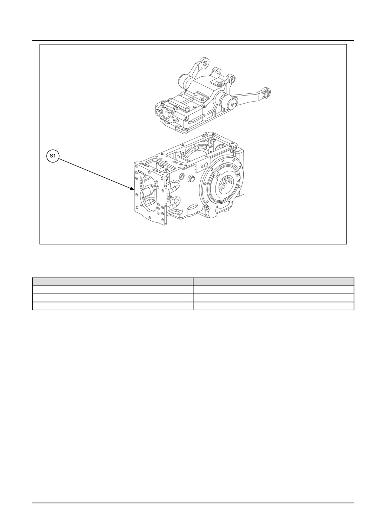
Operation description
Sealant specification
Lift housing to transmission housing (S1)
LOCTITE® 518™
35.2 [35.100] / 4
Hydraulic systems - Main lift system
GNIL14TR04583FB
1
Main lift system - Special tools
Tool description
Tool number
Installer, lift arm seal with protector
9970873
Socket for spool height adjustment
9970874
Adapter hydraulic pressure checking
9970877
35.2 [35.100] / 5
Hydraulic systems - Main lift system
Main lift system - Dynamic description
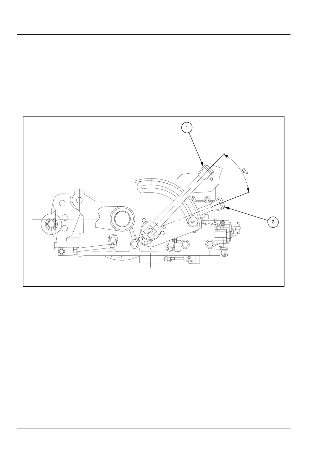
Control levers
A) Position control
B) Draft control
C) Combined operation for position and draft control
The above operations may be chosen in consideration of the work to be carried out, the implement type and the soil
superficial hardness.
GNIL14TR04603FB
1
Position control
Move the draft control lever (2) fully down. Fix the implement position, inside or outside the soil, by moving the lever
(1) up for raising and down for lowering.
The implement movement is proportional to the movement range fixed by means of lever (1).
Draft control
Move the position control lever (2) fully down, have the implement penetrated into the ground till reaching the desired
depth by gradually moving the lever (2) down.
The implement depth reached is proportional to the draft determined by soil hardness.
In this condition the rock shaft keeps the draft required automatically constant.
Once the draft is regulated at the end of the rope is possible to lift the implement with position lever (2) in order to
keep in memory the draft.
During last movement stroke of lever (2) a floating function is obtained and the rock shaft does not control the draft.
35.2 [35.100] / 6
Hydraulic systems - Main lift system
Combined operation for position and draft control
In case of workings carried out under draft control on not-homogeneous soils, during which excessive implement
penetration may occur, it is convenient to use the combined position and draft control.
Have the implement penetrated into the ground and search for the desired working depth in the way described for the
draft control.
When the desired depth is reached, gradually move up the lever 1 till the lower links slightly start raising.
The rock shaft operates under controlled draft, but at the same time it prevents the implement from excessively pen-
etrating into the ground causing a not very uniform work, when coming up against a less hard ground.
For raising and moving the implement penetrated at the end and beginning of each pass, acting on position lever 1
only.
NOTE: It is not correct to find the position with the draft lever 2 because the lifting and lowering of arms with this lever
changes with the top link position.
This can be on neutral-positive-negative-position depending on the draft force, or to change the force on the top link
bracket as per the implement weight.
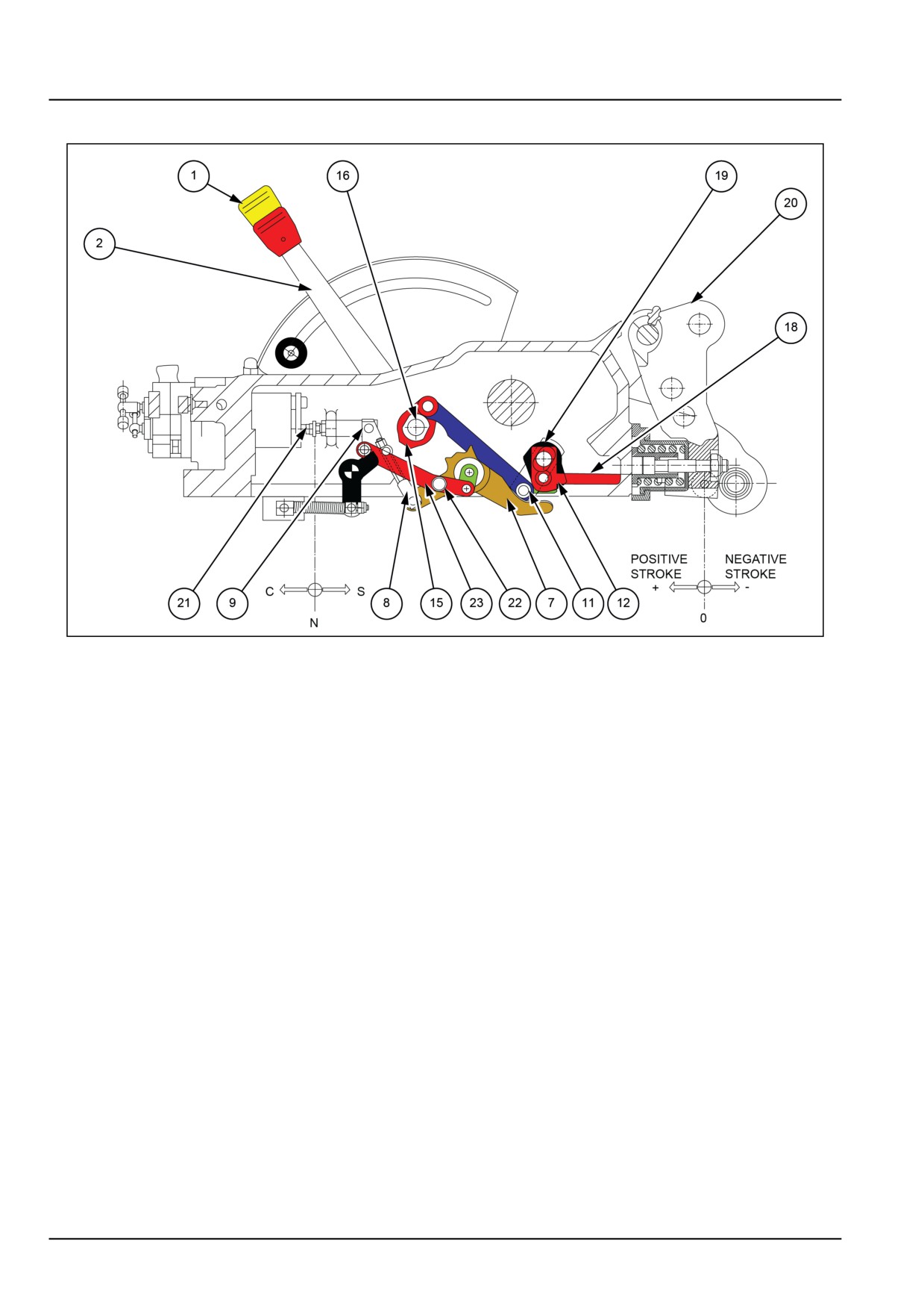
Internal linkage system
A) Functioning of position control
B) Functioning of draft control
C) Combined functioning of position and draft control
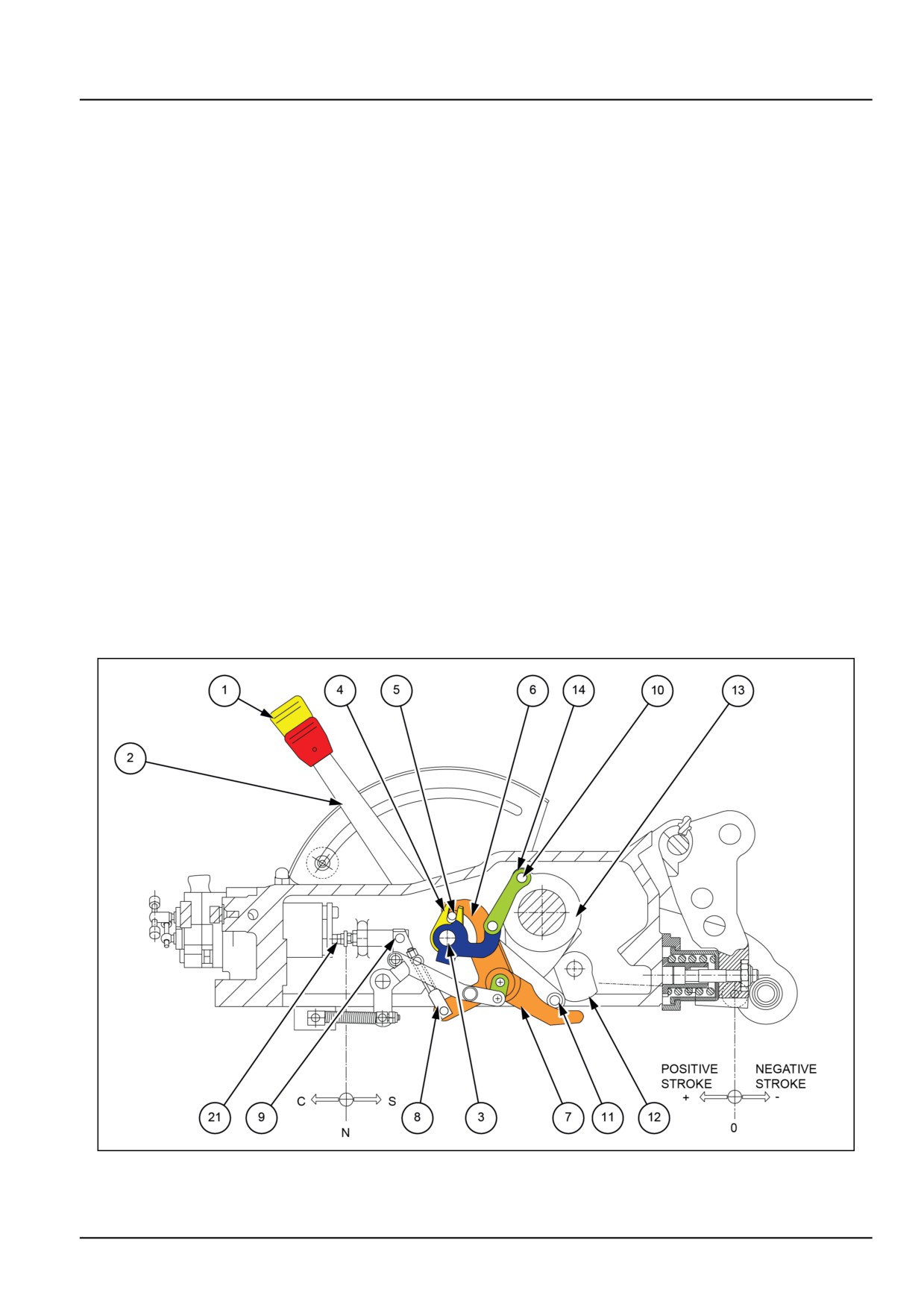
Functioning of position control
GNIL14TR04600FB
2
See 2.
35.2 [35.100] / 7
Hydraulic systems - Main lift system
By positioning the draft control lever (2) against the backstop. The roller (11) which slides on the flywheel (7) of draft
cam (12), will be moved away completely.
In this way the draft levers will not in anyway interfere with the operation of the position control.
The arms are raised by moving the position control lever (1) upward, and the leverage system will act in the following
way.
Crank (4) being an integral part of shaft (3) turns in a clockwise direction and causes roller (5) to slide on the position
cam (6), in turn causing the clockwise rotation of flywheel (7). The flywheel will transmit an anti clockwise rotation,
by means of friction shock absorber (8) to the transmission lever (9) that will bring distributor shaft (21) into delivery
position (C), thus causing the arms to be lifted.
During the lifting movement of the arms, crank (13) with pin (10) will rotate in an anti-clockwise direction, and by
means of the link (14) will cause position cam (6) to rotate clockwise.
When the roller (5) meets the inclined plane of the cam (6), it allows the anti-clockwise rotation of the flywheel (7)
that by means of a friction shock absorber (8) rotates the lever (9) in a clockwise direction, which is pushed by the
spring of the control valve shaft (21) which moves to position (N) (neutral phase) and thus blocking the movement of
the lifting arms.
During the lowering phase of the arms the movements of the levers indicated above will occur in the opposite sense.
The position of the arms, during lifting and lowering, correspond to a specific position of the position control lever (1).
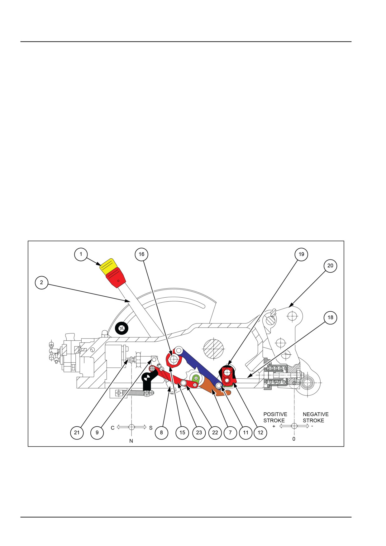
Functioning of draft control
GNIL14TR04601FB
3
See 3.
By positioning the control lever (1) for position control against the backstop. The crank (4) reaches its maximum
position of anti-clockwise rotation. In said position the roller (5) is totally lowered from the inclined plane of position
cam (6) allowing the anti-clockwise rotation of flywheel (7) as well as the clockwise rotation of the transmission lever
35.2 [35.100] / 8
Hydraulic systems - Main lift system
(9) that is pushed by the spring of shaft (21) which in turn will position itself for the discharge position (S). In this way
the position levers will not interfere with the functioning of the draft control levers.
By positioning the draft control lever (2) against backstop. Draft control shaft (16) is caused to rotate clockwise.
The crank (15) being an integral part of shaft (16),will reach its extreme position of clockwise rotation, and by means
of tension rod (17) will move roller (11), the latter acting on the draft cam (12). This causes flywheel (7) to rotate
clockwise which by means of function shock absorber (8) produces the anti-clockwise rotation of transmission lever
(9) thus setting the distributor shaft (21) in delivery position (C) and consequently lifting the arms.
The arms will come to a stop only as soon as the piston comes into contact with the pin of the limit stop (22).
This limit stop, by means of tension rod (23) causes lever (9) to rotate clockwise, thereby compressing the spring of
friction shock absorber (8) and thus releasing shaft (21) which now can move to the neutral position (N) where it is
pushed outward by its spring.
Moving the draft control lever (2) toward backstop (E), the leverage system will function in the following manner:
The crank (15) being an integral part of the draft shaft (16), rotates counter-clockwise and by means of tension rod
(17) causes roller (11) to slide on flywheel (7).
The roller (11) when it meets the inclined plane of the draft cam (12), permits the counter-clockwise rotation of fly-
wheel (7) which by means of shock absorber (8) will rotate transmission lever (9) in a clockwise manner thus leaving
distributor shaft (21) free to move into neutral position (N) and continuing the movement of lever (2), in the discharge
position (S), causing the arms to lower.
In fact, during the initial part of the movement toward backstop (E), of draft control lever (2) the corresponding lowering
of the arms does not happen yet.
The traction force on the top link point (20) acts on tension rod (18) in the direction indicated by the arrow (+) (positive)
causing flywheel (19) to rotate clockwise together with draft cam (12) which is fastened to the same pin.
When the inclined plane of draft cam (12) meets roller (11), a clockwise rotation of flywheel (7) is achieved which
by means of shock absorber (8) will cause transmission lever (9) to rotate counter-clockwise thereby moving the
distributor shaft (21) into neutral position (N) and stopping the movement of the arms.
As the traction force is increased, draft cam (12) will further move roller (11) thus incrementing the movement as
described above.
The distributor shaft (21) will move from neutral position (N) to delivery position (C) causing the arms to be lifted.
When the traction force diminishes, shaft (21) will return to the neutral position or to the lowering position which will
mean an inverse movement of the leverage systems to what is described above.
35.2 [35.100] / 9
Hydraulic systems - Main lift system
Combined functioning of position and draft control
GNIL14TR04602FB
4
To utilise the lifting device in this condition it is necessary to observe the following instructions:
• Move the position control lever (1) upwards with respect to the backstop (E) until the maximum working depth has
been attained.
• Determine the desired minimum working depth by operating the draft control lever and raising it from its zero position
so that roller (11), acting on the draft cam (12) will move the distributor shaft (21) into the lifting position (C) and
causing a further upward movement of the lifting arms.
Due to the position previously established by position control lever (1), flywheel (7), roller (4) and position cam (6),
the distributor shaft (21) is prevented from entering the lowering position (S) and therefore the arms cannot sink even
though the traction force acting on the top link point (20) will tend to diminish and putting stress on the tension rod
(18) in the direction of arrow (-) (negative).
This condition will not prevent the rock shaft from operating with the draft control when, in the presence of more
consistent soil, the traction force on the top link (20) will tend to increase, exerting pressure on the tension rod (18) in
the direction of arrow (+) (positive).
Consequently the combined operation of position and draft control will limit variations in height towards the ground,
as happens during the use of the draft control, and at the same time ensuring the maximum possible depth desirable.
35.2 [35.100] / 10
Hydraulic systems - Main lift system
Main lift system - Remove
WARNING
Avoid injury!
Handle all parts carefully. Do not place your hands or fingers between parts. Use Personal Protec-
tive Equipment (PPE) as indicated in this manual, including protective goggles, gloves, and safety
footwear.
Failure to comply could result in death or serious injury.
W0208A
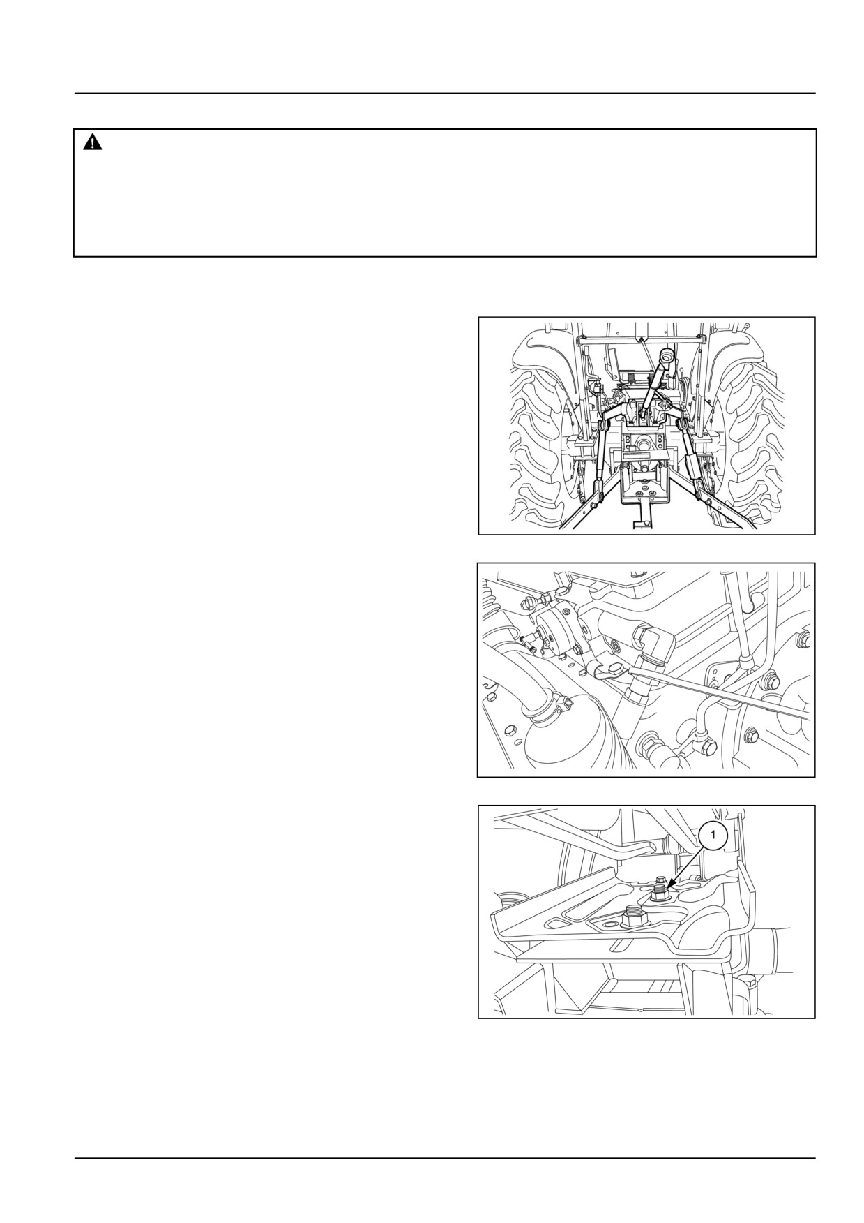
Remove the hydraulic lift from the rear axle housing as
follows:
1. Remove three-point linkages (top link, lower link and lift
rod) from the tractor.
76099304N
1
2. Disconnect delivery pipe and return pipe from the lift
assembly.
GNIL14TR00800AA
2
3. Disconnect the wiring coupler. Loosen the bolts (1).
Remove the operator’s seat from the hydraulic lift.
GNIL14TR04607AB
3
35.2 [35.100] / 11
Hydraulic systems - Main lift system
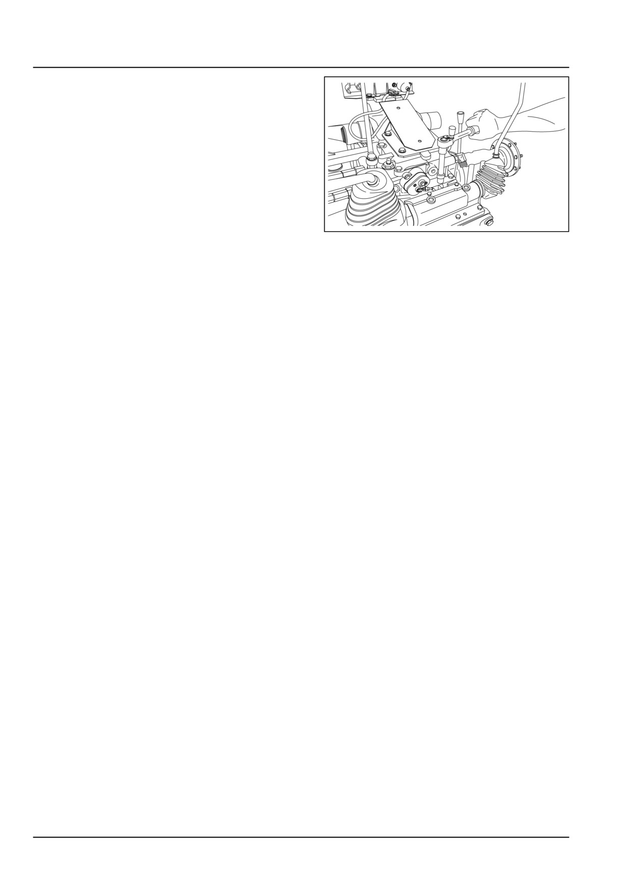
4. Loosen the bolts securing hydraulic lift housing to trans-
mission housing.
5. Lift the hydraulic lift assembly using suitable hoist and
place it on a flat surfaced table.
NOTICE: Never lift the housing by holding distributor knobs
and delicate parts.
GNIL14TR00799AA
4
35.2 [35.100] / 12
Hydraulic systems - Main lift system
Main lift system - Install
CAUTION
Pinch hazard!
Always use suitable tools to align mating parts. DO NOT use your hand or fingers.
Failure to comply could result in minor or moderate injury.
C0044A
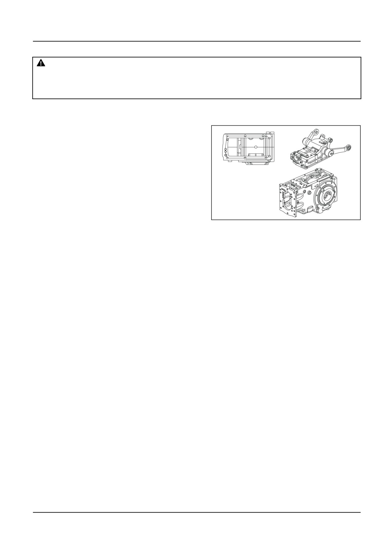
Refit the hydraulic lift on the transmission housing as
follows.
1. Re-installation follows the removal procedure in re-
verse
2. Before refitting the hydraulic lift in the rear transmission
casing, clean and degrease the mating surfaces thor-
oughly and apply a strip of sealing compound of about
2.00 mm (0.08 in) diameter as shown in the figure.
3. Apply the torque settings.
GNIL14TR04609AA
1
35.2 [35.100] / 13
Hydraulic systems - Main lift system
Main lift system - Disassemble
WARNING
Avoid injury!
Handle all parts carefully. Do not place your hands or fingers between parts. Use Personal Protec-
tive Equipment (PPE) as indicated in this manual, including protective goggles, gloves, and safety
footwear.
Failure to comply could result in death or serious injury.
W0208A
NOTE: Draft sensing unit and related external linkages can be disassembled and assembled with the lift unit mounted
on the tractor.
Draft sensing unit - Removal
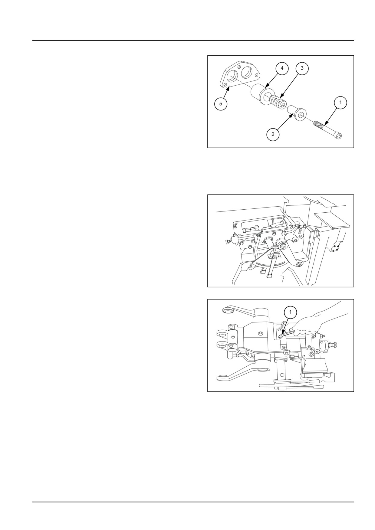
1. Loosen the bolts (1) from the sensing unit.
GNIL14TR04617AB
1
2. Remove the lock (1) and remove draft link (2).
GNIL14TR04618AB
2
3. Loosen bolts (1) and set screw.
4. Remove the pin as shown in figure.
5. Remove the sensing unit from the lift housing.
GNIL14TR04619AB
3
35.2 [35.100] / 14
Hydraulic systems - Main lift system
Draft sensing unit - Disassembly
6. Loosen set screws (1).
GNIL14TR04621AB
4
7. Disassemble roller (2), springs (3), cover (4), flange (5)
from the sensing unit.
Rear lift internal controls removal
8. Remove the lift assembly from the transmission hous-
ing and fix on a rotary stand. See Main lift system -
Remove (35.100).
GNIL14TR04642AA
5
9. Loosen the set screws (1).
GNIL14TR04624AB
6
35.2 [35.100] / 15
Hydraulic systems - Main lift system
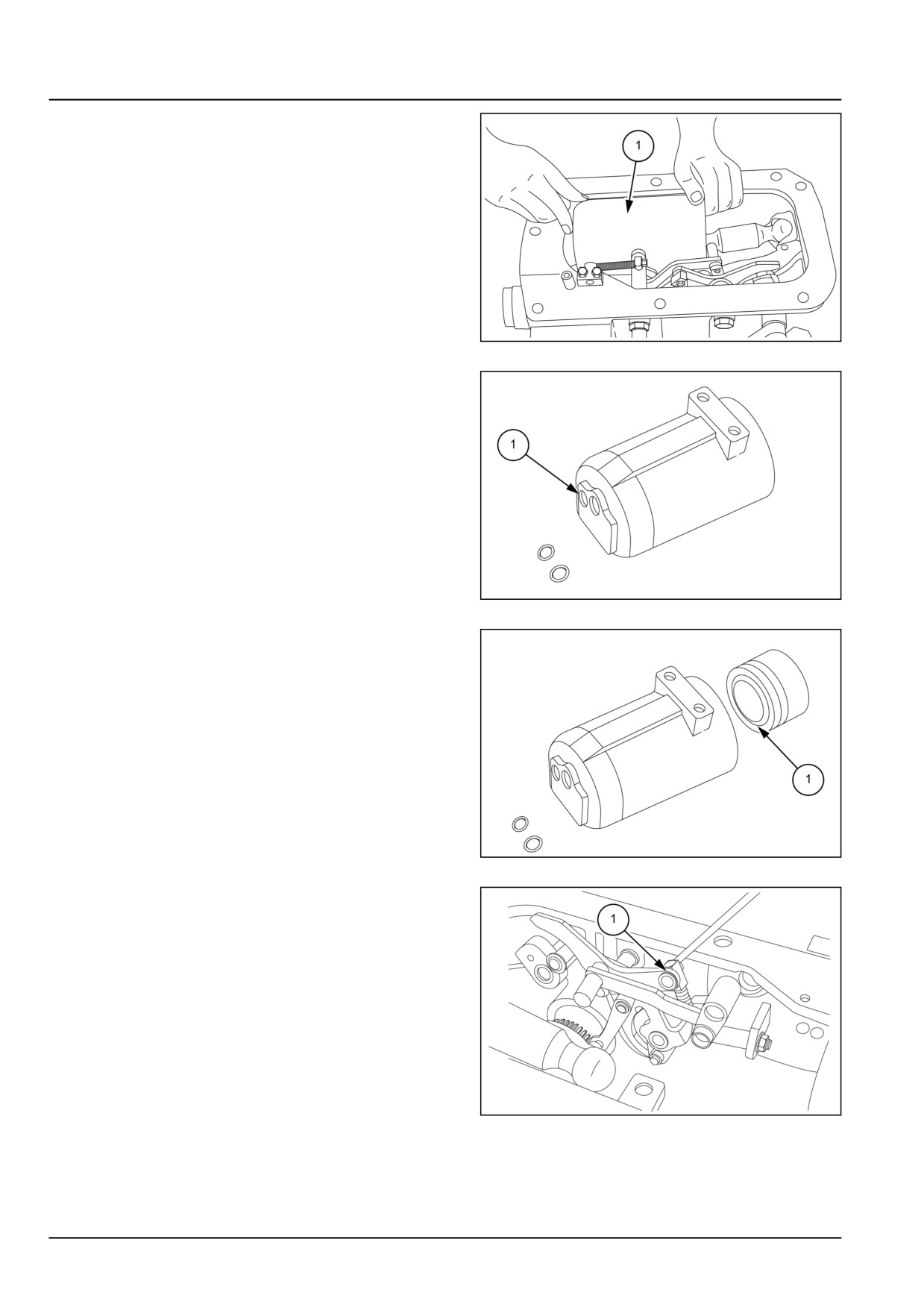
10. Remove the cylinder (1) from hydraulic lift housing.
GNIL14TR04625AB
7
NOTE: Retrieve the seal (1) from head of cylinder.
GNIL14TR04626AB
8
11. Remove the piston (1) from the cylinder by pushing
with a suitable aluminium rod from the front side.
GNIL14TR04627AB
9
12. Remove locks and disassemble lever (1).
GNIL14TR04631AB
10
35.2 [35.100] / 16
Hydraulic systems - Main lift system
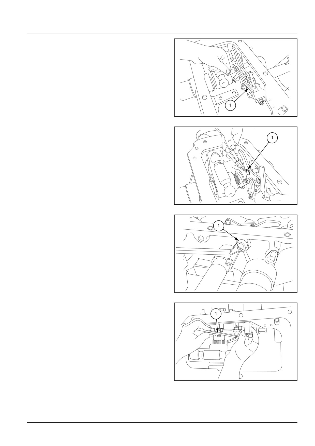
13. Remove linkage (1).
GNIL14TR04633AB
11
14. Remove the lock (1) from the compensator pin.
GNIL14TR04632AB
12
15. Unscrew the compensator pin until face of the pin
comes out of the compensator.
GNIL14TR04634AB
13
16. Remove linkages as shown in figure.
GNIL14TR04635AB
14
35.2 [35.100] / 17