New Holland Tractor Workmaster 50 / Workmaster 60 / Workmaster 70 / Tier 4B (final). SERVICE MANUAL - page 8
Contents
Rear axle system - 27
Rear bevel gear set and differential - 106
TECHNICAL DATA
Rear bevel gear set and differential
General specification
3
Torque
3
Special tools
4
Sealing
4
FUNCTIONAL DATA
Rear bevel gear set and differential
Sectional view
6
SERVICE
Rear bevel gear set and differential
Remove
7
Install
12
Differential
Disassemble
14
Inspect
17
Assemble
18
Backlash
19
Bevel pinion
Remove
21
Install
24
DIAGNOSTIC
Rear bevel gear set and differential
Troubleshooting
25
27.2 [27.106] / 2
Rear axle system - Rear bevel gear set and differential
Rear bevel gear set and differential - General specification
Pinion to crown wheel and differential
Pinion and crown wheel ratio
Pinion to crown wheel backlash
0.180 mm (0.007 in) - 0.230 mm (0.009 in)
Differential
4 pin
Differential lock control type
Mechanical operated with foot pedal
Differential lock free spring length
106.000 mm (4.170 in)
Compressed spring length, under a load of
82.000 mm (3.230 in)
365000.0 Kg/cm² (5191520.3 psi)
Side gear to differential gear backlash
0.100 mm (0.004 in) - 0.250 mm (0.010 in)
Differential gear pin diameter
21.960 mm (0.865 in) - 21.939 mm (0.864 in)
Bore diameter on differential gears for pin
22.098 mm (0.870 in) - 22.065 mm (0.869 in)
Bore diameter on differential case for pin
22.020 mm (0.867 in) - 22.000 mm (0.866 in)
Pin to differential gear clearance
0.159 mm (0.006 in) - 0.040 mm (0.002 in)
Pin to differential case clearance
0.082 mm (0.003 in) - 0.040 mm (0.002 in)
Rear bevel gear set and differential - Torque
Description
Thread size
Torque
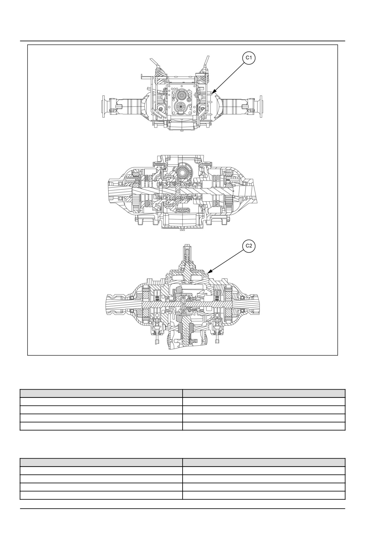
Rear axle to transmission housing attaching bolts (C1)
M12 x 1.25
10 kgf (22 lbf)
Power Take-Off (PTO) cover bolts (C2)
M12
10 kgf (22 lbf)
Ring gear bolts (C3)*
M10
6 kgf (13 lbf)
Drain plug (C4)
M22
4.5 kgf (10 lbf)
27.2 [27.106] / 3
Rear axle system - Rear bevel gear set and differential
GNIL14TR04239GB
1
Rear bevel gear set and differential - Special tools
Tool description
Tool number
Differential plate check nut tightening tool
9971349
Installer oil seal wheel side (heavy duty)
84261386
Set screw socket 6.000 mm (0.236 in)
84261394
Yoke and spreader
291051 and 291052
Rear bevel gear set and differential - Sealing
Operation description
Sealant specification
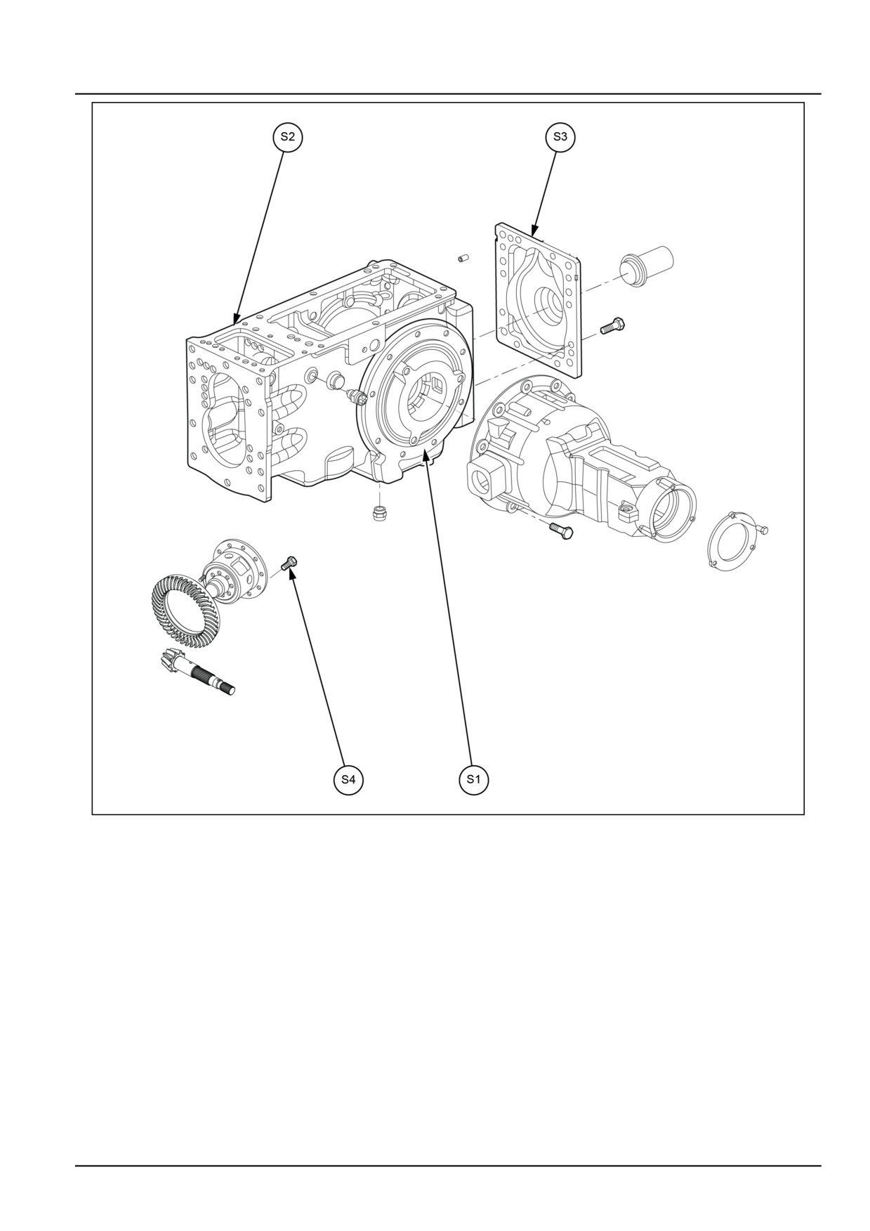
Rear axle to transmission housing (S1)
LOCTITE® 518
Lift housing to transmission housing (S2)
LOCTITE® 518
Power Take-Off (PTO) cover plate (S3)
LOCTITE® 518
Crown wheel bolts (S4)
LOCTITE® 243
27.2 [27.106] / 4
Rear axle system - Rear bevel gear set and differential
GNIL14TR04240GB
1
27.2 [27.106] / 5
Rear axle system - Rear bevel gear set and differential
Rear bevel gear set and differential - Sectional view
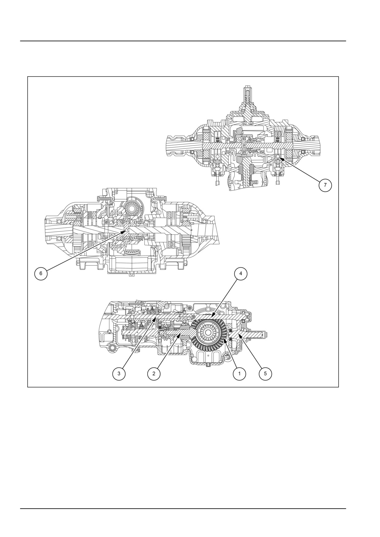
Crown wheel and differential assembly
GNIL14TR04241GB
1
1.
Crown wheel
5.
Power Take-Off (PTO) shaft
2.
Pinion shaft
6.
Differential assembly
3.
Input shaft
7.
Brake
4.
Power Take-Off (PTO) input shaft
27.2 [27.106] / 6
Rear axle system - Rear bevel gear set and differential
Rear bevel gear set and differential - Remove
Crown wheel and differential housing
To remove the crown wheel and differential housing,
final drive housing, brake assembly and Power Take-Off
(PTO) assembly has to be removed.
Remove the rear axle housing as follows:
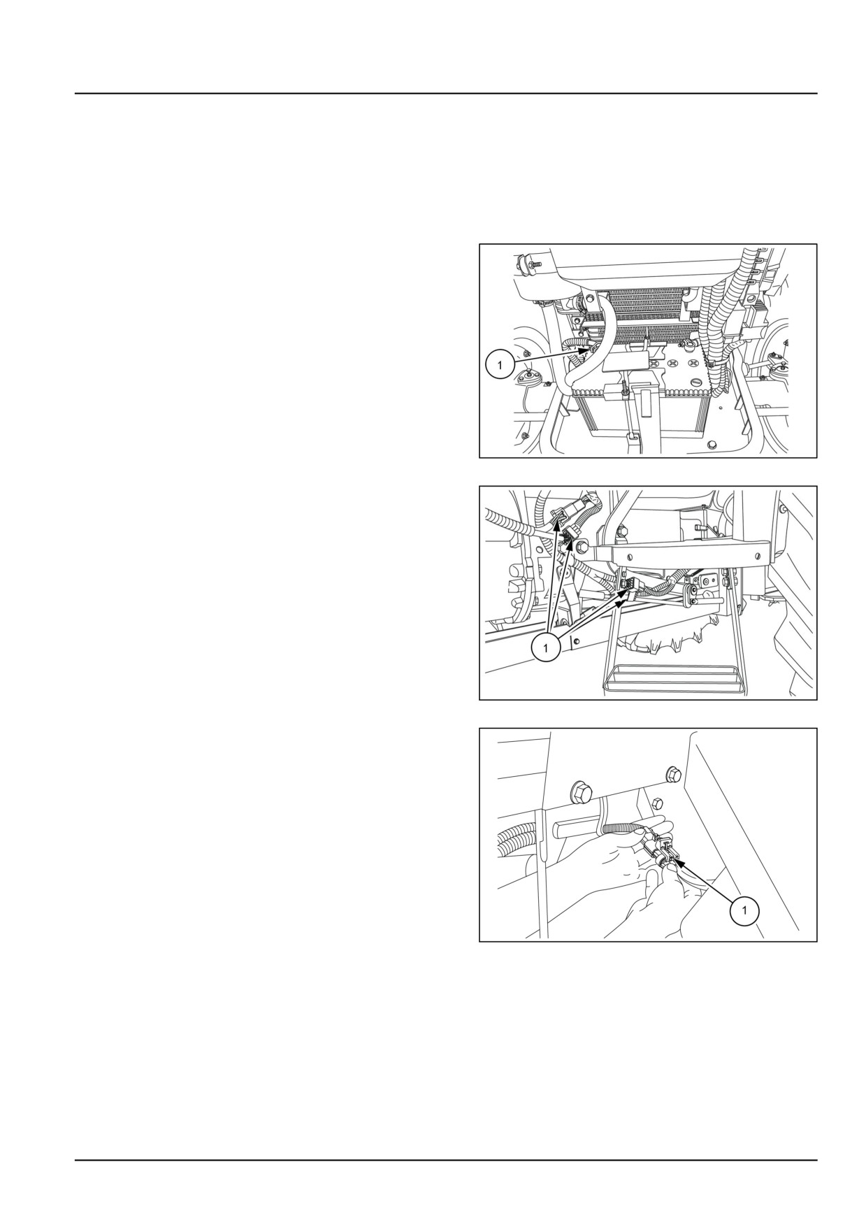
1. Detach the negative cable (1) from the battery and in-
sulate.
GNIL14TR00784AA
1
2. Disconnect the electrical couplings (1).
GNIL14TR00797AA
2
3. Detach electric connections (1) between left and right-
hand side fenders.
GNIL14TR04245AB
3
27.2 [27.106] / 7
Rear axle system - Rear bevel gear set and differential
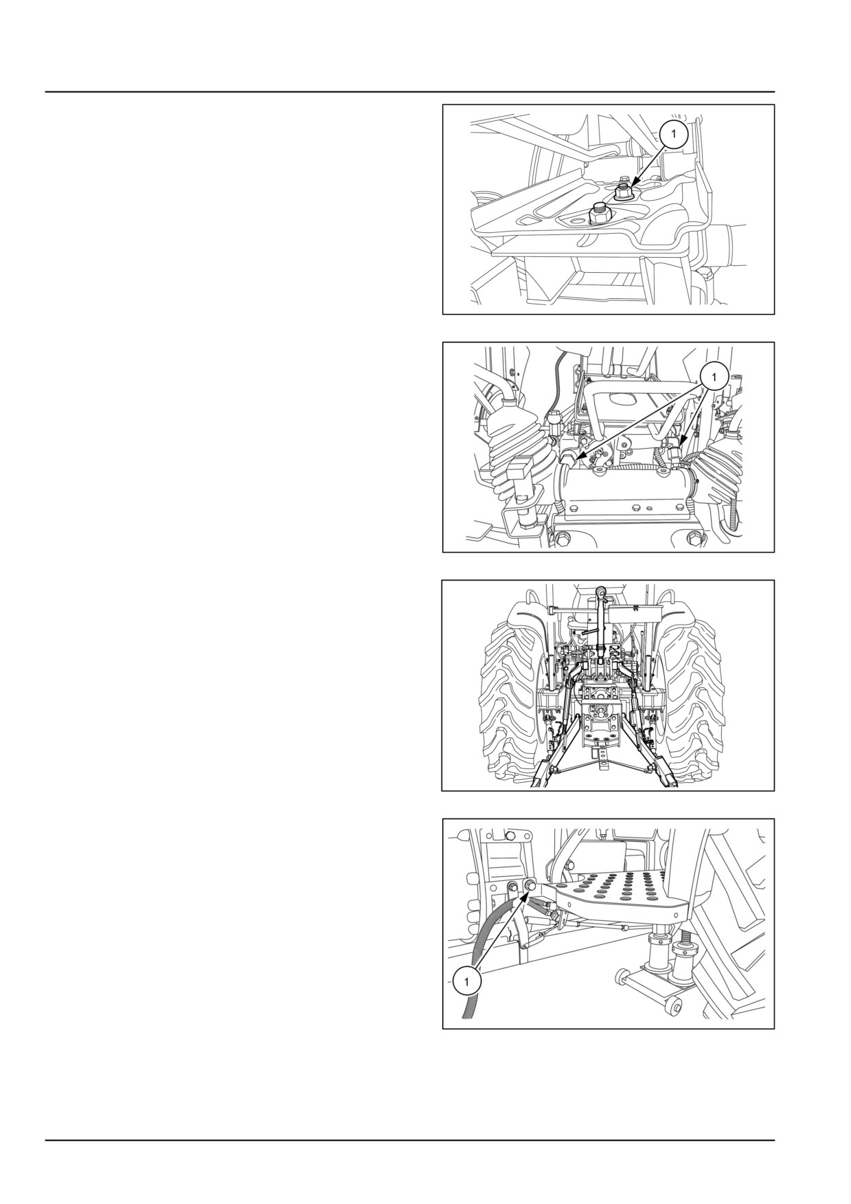
4. Loosen the bolts (1), detach electrical connection and
remove operator seat from the hydraulic housing.
GNIL14TR04246AB
4
5. Disconnect hydraulic lines (1) on the hydraulic lift body.
GNIL14TR00798AA
5
6. Remove three point linkages from the tractor.
GNIL14TR00562AA
6
7. Loosen bolts securing foot rest to fender on both sides.
GNIL14TR00767AA
7
27.2 [27.106] / 8
Rear axle system - Rear bevel gear set and differential
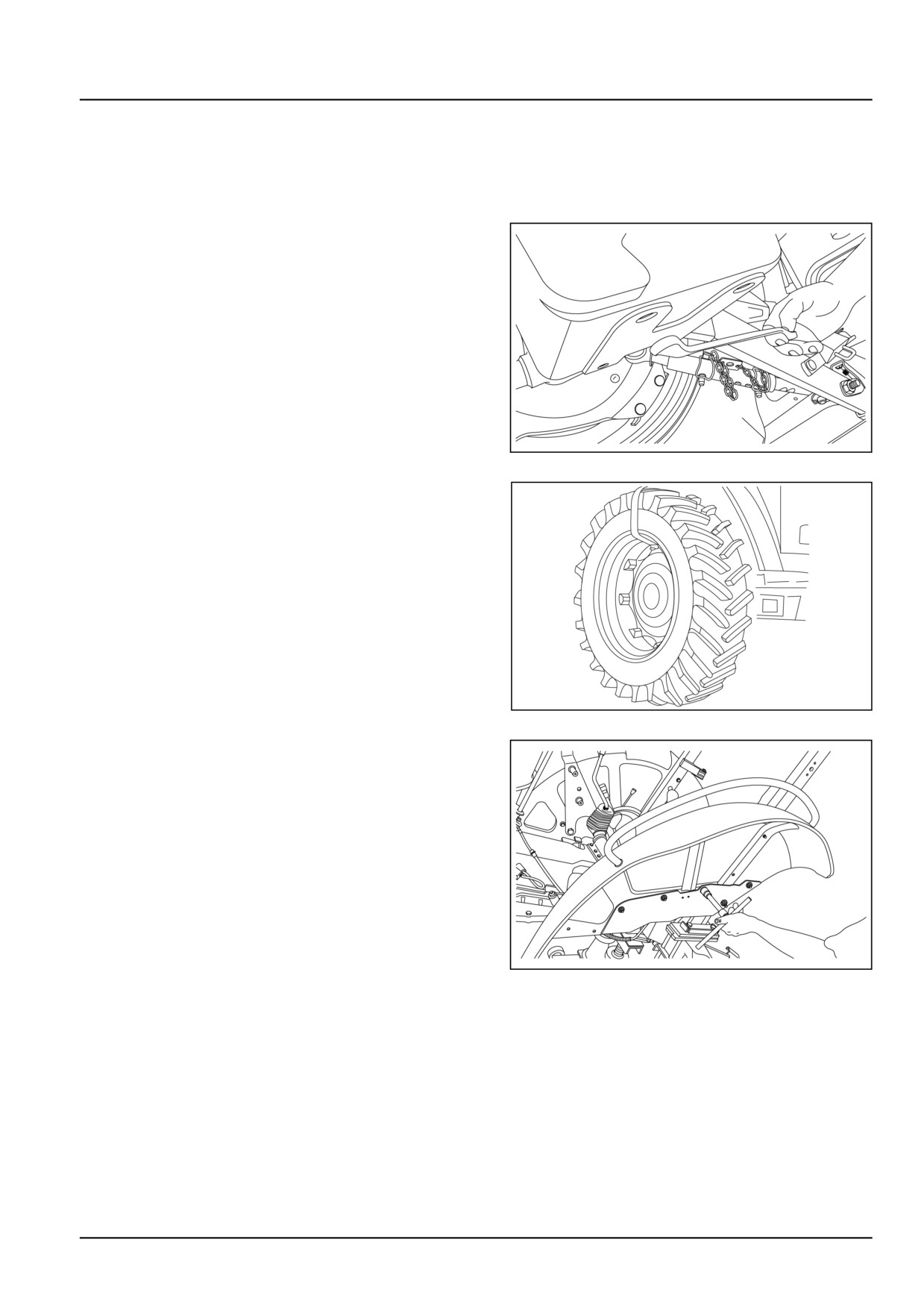
8. Place the wedges at front and back on both sides of
front tires.
9. Jack up rear axle of the tractor and place two suitable
stands under transmission housing to raise the wheels
off the ground.
10. Drain oil from the transmission housing.
GNIL14TR00564AA
8
11. Remove both left and right-hand side wheels.
GNIL14TR04252AA
9
12. Loosen the bolts and remove fenders from both sides.
GNIL14TR00790AA
10
27.2 [27.106] / 9
Rear axle system - Rear bevel gear set and differential
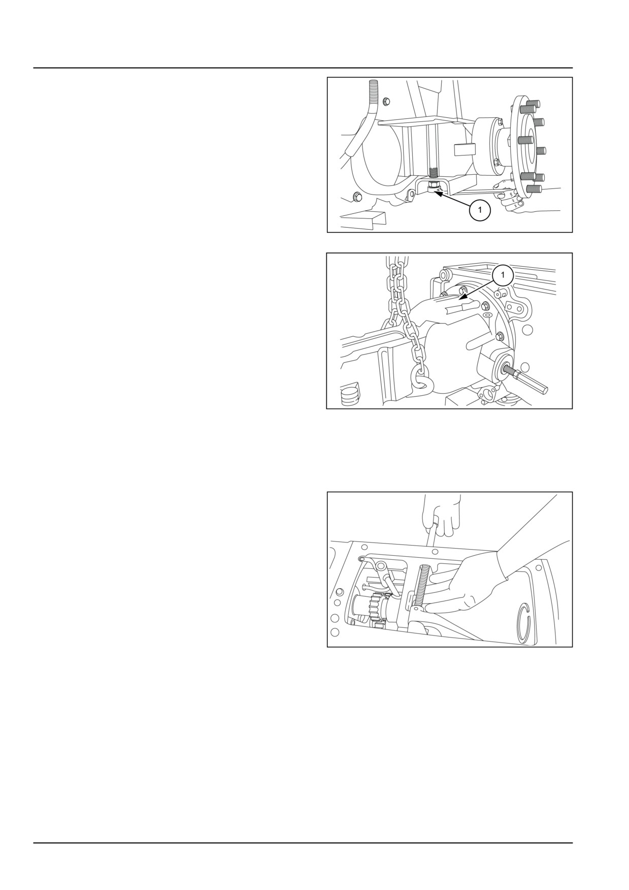
13. Loosen the bolts (1) and remove ROPS.
GNIL14TR04251AA
11
14. Wrap suitable chain or nylon rope on the final drive
housing (1) and connect it to a hoist. Loosen attaching
bolts and remove the entire final drive.
GNIL14TR04253AB
12
15. Repeat for the final drive housing on the other side.
16. Remove the cover plate by removing Allen screw (1)
and remove cover plate (2). Retrieve oil rings 2 num-
bers from the housing and cover plate respectively.
17. Loosen the bolts securing hydraulic lift housing to
transmission housing. Lift the hydraulic lift assembly
using suitable hoist and place it on a flat surfaced
table.
18. Remove Power Take-Off (PTO) engaging levers and
differential lock.
GNIL14TR04255AA
13
27.2 [27.106] / 10
Rear axle system - Rear bevel gear set and differential
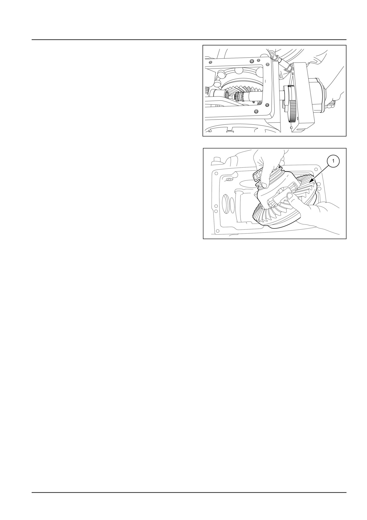
19. Remove PTO RPM sensor cable. Loosen the rear
Power Take-Off (PTO) cover bolts and pull out the
cover along with Power Take-Off (PTO) shaft and
Power Take-Off (PTO) input shaft assembly. See
Rear mechanical control - Remove (31.101).
GNIL14TR00742AA
14
20. Take out the differential assembly along with crown
wheel.
GNIL14TR04258AB
15
27.2 [27.106] / 11
Rear axle system - Rear bevel gear set and differential
Rear bevel gear set and differential - Install
1. Re-install the differential housing observing the follow-
ing.
• Re-assembly follows the disassembly procedure in
reverse. See Rear bevel gear set and differential
- Install (27.106).
• Check seals and replace if damaged.
• Before reassembling housings supports and covers
thoroughly clean and degrease mating surfaces and
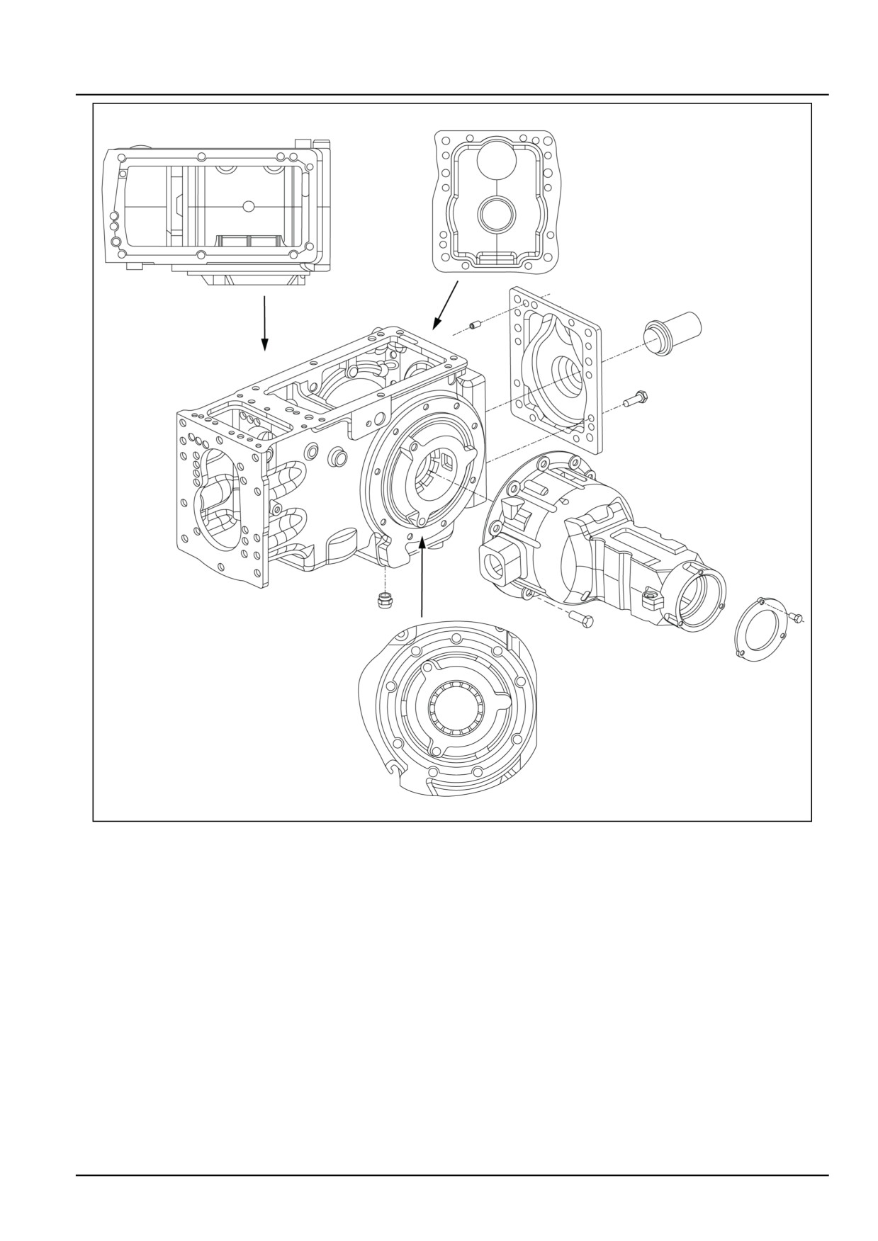
apply a bead of liquid gasket of approx. 2.000 mm
(0.079 in) of diameter following the patterns shown
in the figure.
• Tighten to correct torques.
• Preload tapper roller bearings by adding and remov-
ing shims and set crown pinion backlash by following
the procedure given below.
27.2 [27.106] / 12
Rear axle system - Rear bevel gear set and differential
GNIL14TR04259GA
1
Pattern for application of sealant during installation of Power Take-Off (PTO) cover, final drive housing
and mechanical lift housing.
• Check the backlash with the help of dial gauge.
Permissible backlash is 0.180 - 0.230 mm (0.007 -
0.009 in), if it is less than tighten left-hand side ring
nut after slightly loosening right-hand side ring nut.
• If it is more than 0.180 - 0.230 mm (0.007 - 0.009 in)
then first loosen left-hand side ring nut and then
tighten right-hand side ring nut.
27.2 [27.106] / 13
Rear axle system - Rear bevel gear set and differential
Differential - Disassemble
WARNING
Avoid injury!
Handle all parts carefully. Do not place your hands or fingers between parts. Use Personal Protec-
tive Equipment (PPE) as indicated in this manual, including protective goggles, gloves, and safety
footwear.
Failure to comply could result in death or serious injury.
W0208A
With the assembly removed from the rear axle housing
proceed as follows:
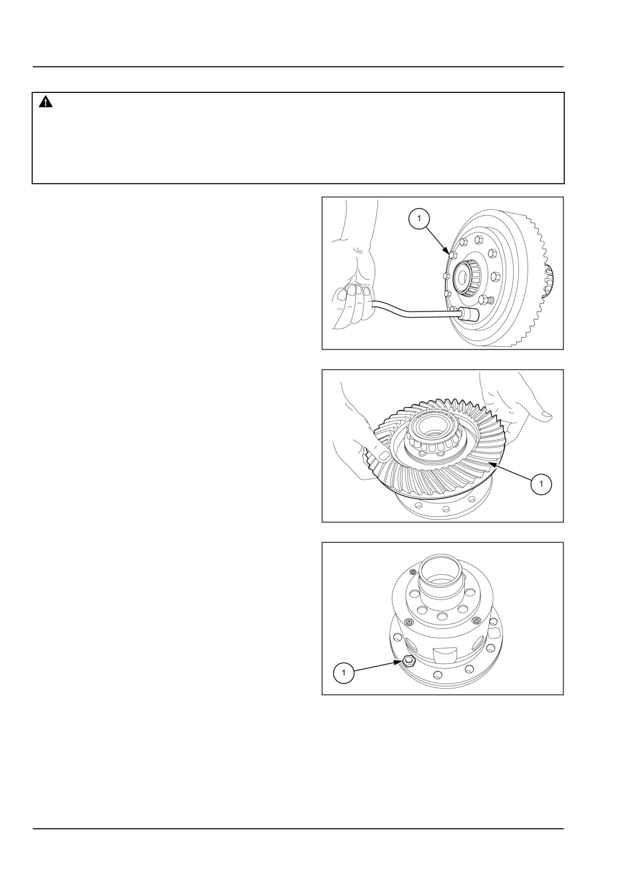
1. Loosen the crown wheel attaching bolts (1).
GNIL14TR04260AB
1
2. Detach the crown wheel (1) from the differential hous-
ing.
GNIL14TR04261AB
2
3. Loosen and remove all the bolts (1) from the casing.
GNIL14TR04262AB
3
27.2 [27.106] / 14
Rear axle system - Rear bevel gear set and differential
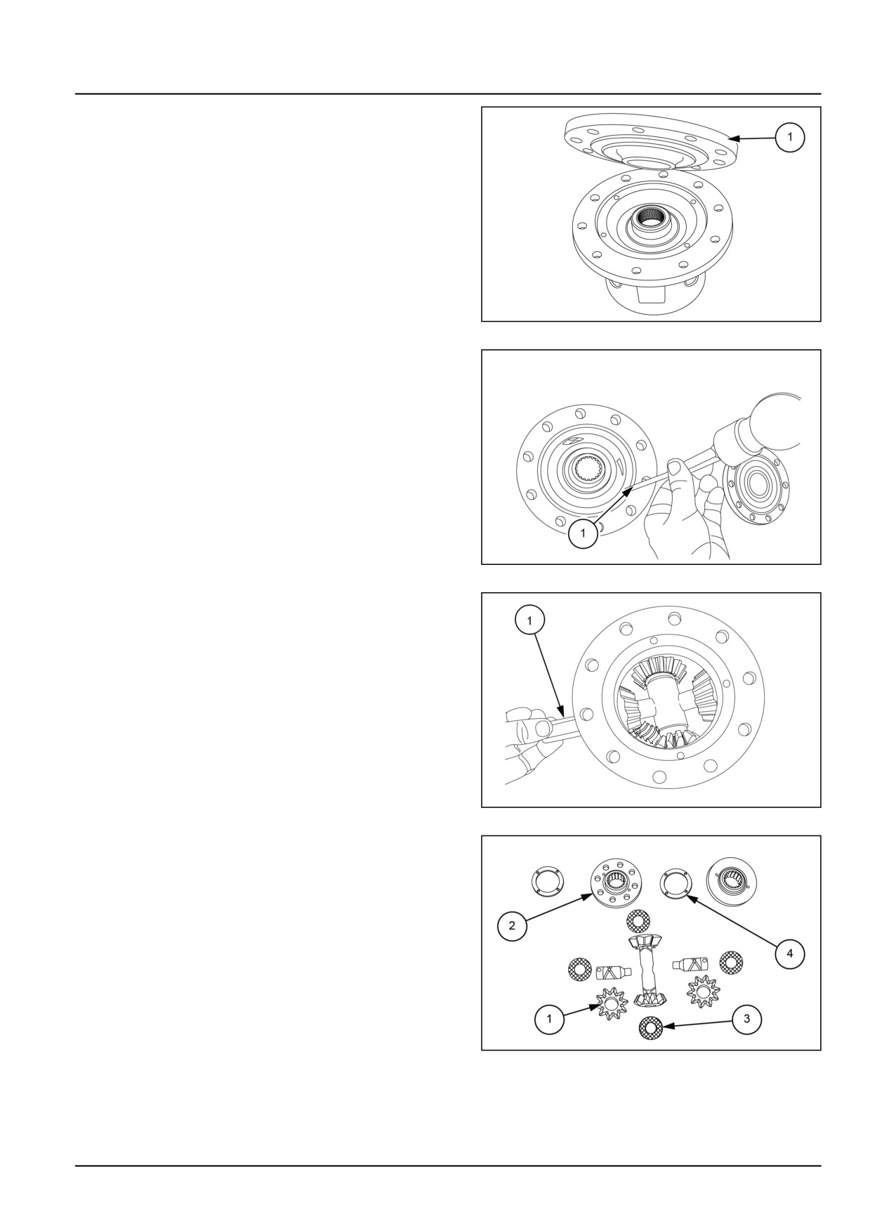
4. Lift the cover (1) as shown to get access to differential
gears.
GNIL14TR04263AB
4
5. Remove the locking pin (1) locking the differential gear
pivot pin.
GNIL14TR04264AB
5
6. Remove the pivot pin (1) and withdraw the side gears
from the differential housing along with trust washer.
GNIL14TR04265AB
6
NOTE: Four differential gear (1) and side gear (2) have
thrust washers with same thickness.
GNIL14TR04266AB
7
27.2 [27.106] / 15
Rear axle system - Rear bevel gear set and differential
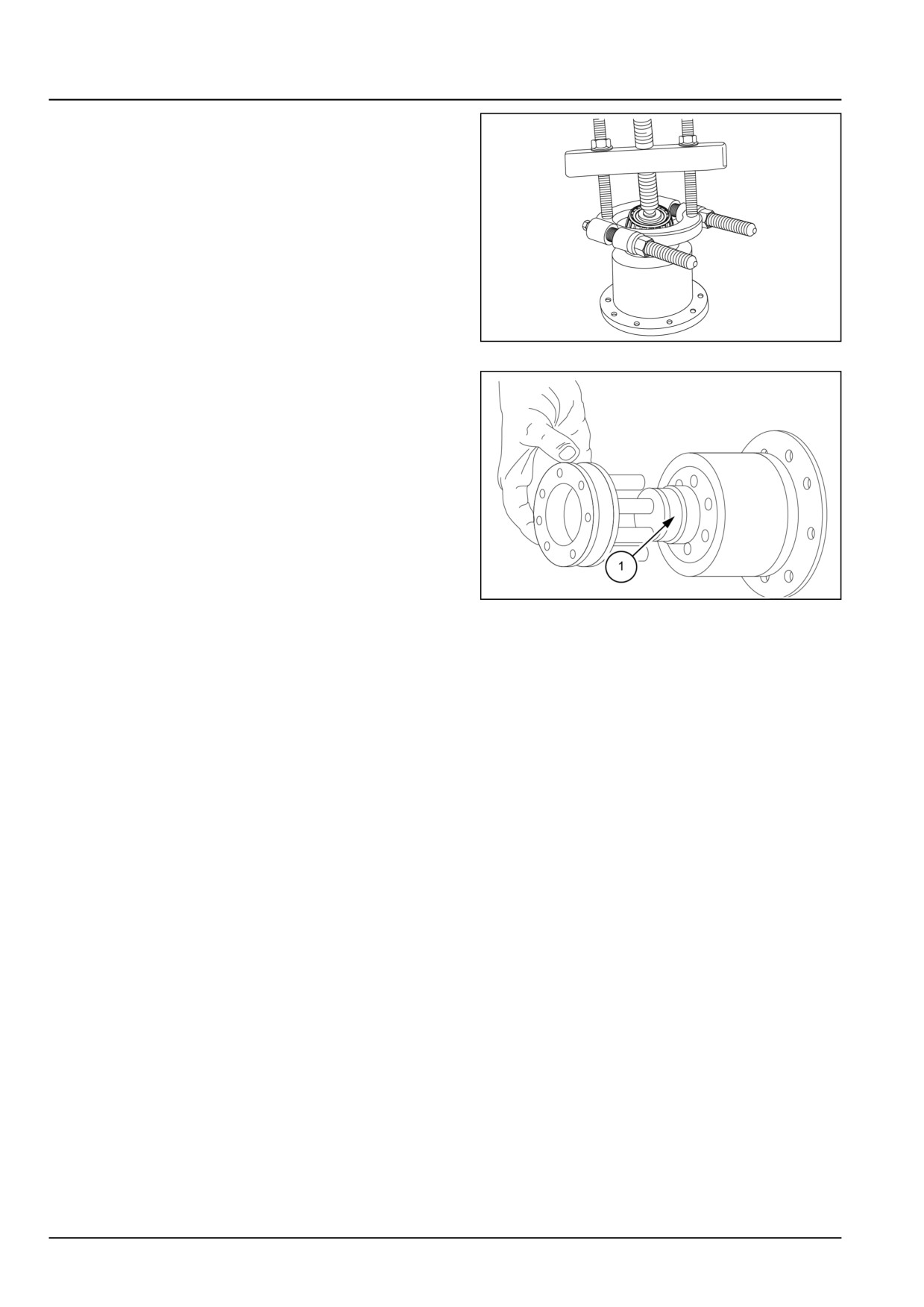
7. Using suitable puller special tool number 291051 and
291052 remove the bearings from both the sides.
GNIL14TR04267AA
8
8. Remove the differential lock clutch from the housing.
GNIL14TR04268AB
9
27.2 [27.106] / 16
Rear axle system - Rear bevel gear set and differential
Differential - Inspect
Inspect all gears thrust washers bearings for any kind
of damages or wear. Replace if necessary.
27.2 [27.106] / 17
Rear axle system - Rear bevel gear set and differential
Differential - Assemble
CAUTION
Pinch hazard!
Always use suitable tools to align mating parts. DO NOT use your hand or fingers.
Failure to comply could result in minor or moderate injury.
C0044A
Re-install all the components of the differential assem-
bly observing the following.
• Re-assembly follows the disassembly procedure in
reverse.. See Differential - Disassemble (27.106).
• Set crown or pinion backlash and total preload set-
ting. See Differential - Backlash (27.106).
• Use suitable tools to fit bearings.
• Tighten to correct torques.
• Use thread sealant LOCTITE® 243™ on crown wheel
bolts.
• Set sun star backlash to 0.180 - 0.250 mm (0.007 -
0.010 in).
27.2 [27.106] / 18
Rear axle system - Rear bevel gear set and differential
Differential - Backlash
Differential pinion and side gear backlash adjustment
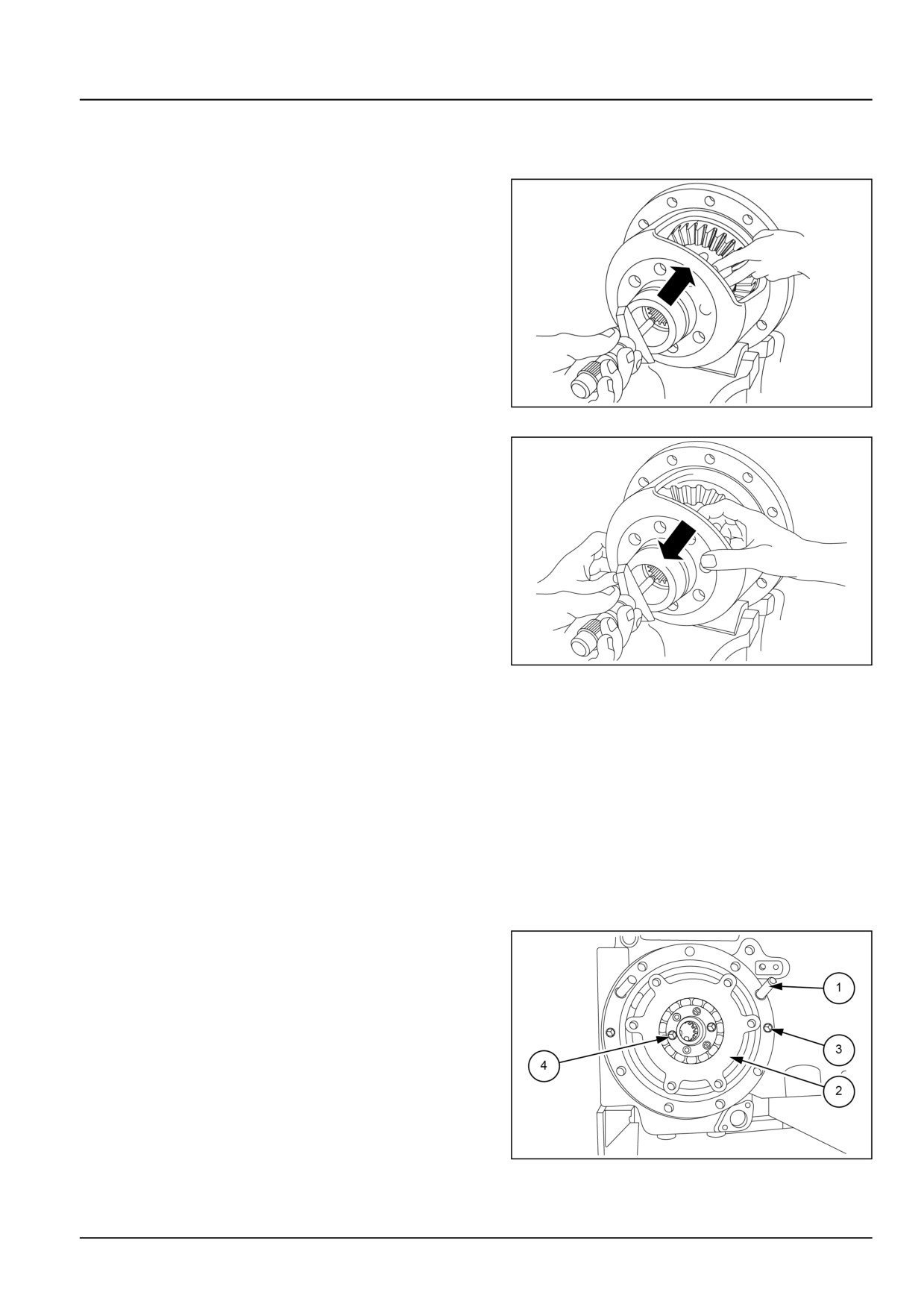
Fit the two side gears (15) in the differential carrier with-
out the shims (12).
Install differential pinions
(13) complete with thrust
washer (14) and journal (3) and tighten bolts (1) a few
turns to prevent journal work out.
Bring left-hand side gear into full contact with differential
pinion.
Using a depth gauge measure dimension (H1) at two
diametrically opposed points and average the two read-
ings.
GNIL14TR04269AB
1
Then push side gear into contact with differential carrier
and measure dimension (H2).
Repeat the same operations on right-hand side gear.
End float of each side gear without the baulk ring must
be:
Gs or Gd = H1 - H2
where:
Gs = Left-hand side gear end float.
Gd = Right-hand side gear end float.
H1 and H2 = Dimensions measured on left-hand side
or right-hand side gears.
Normal differential pinion and side gear backlash is
0.15 mm (0.01 in).
Note that the average ratio normal backlash to the
GNIL14TR04270AB
2
equivalent side gear end float is 1 to 1.7.
Side gear end float corresponding to normal backlash
will be:
0.15 x 1.8 = 0.250 mm (0.010 in).
Consequently the shim thickness required in the differ-
ential carrier is given by:
Ss = Gs - 0.25 (for left-hand side gear)
Sd = Gd - 0.25 (for right-hand side gear)
Available shims are
1.200
-
2.000 mm
(0.047
-
0.079 in).
Install closest to calculated thickness.
Adjustment of bevel wheel bearings and crown pinion
NOTE: Place O-ring in the housing before fitting cover
plate.
1. Fit the locator pins (1) and fit the cover plate (2) tighten
the plate with Allen screws (3), screw out two Allen
screws (4) and remove lock plate from both sides.
GNIL14TR04271AA
3
27.2 [27.106] / 19
Rear axle system - Rear bevel gear set and differential
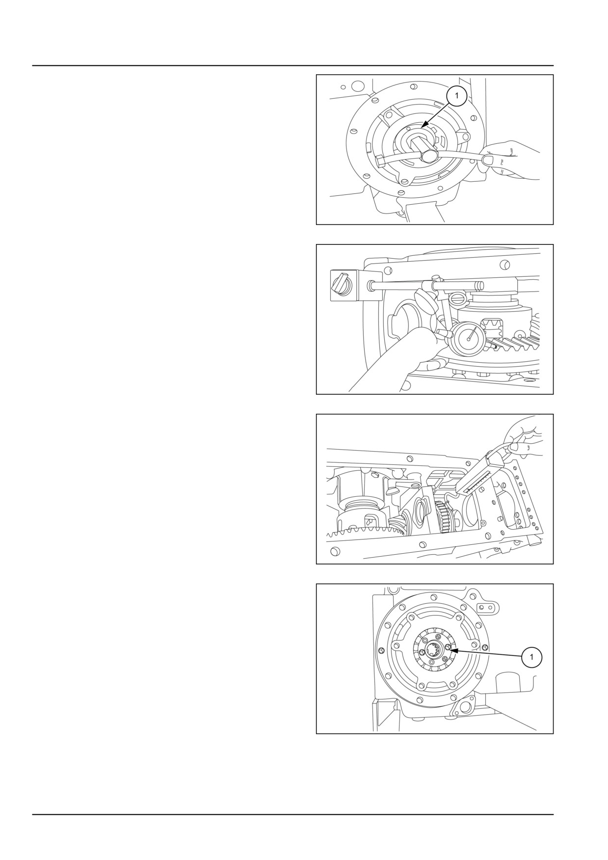
2. Tighten left-hand side ring nut (1) using special tool
number 9971349 until minimum backlash between the
bevel teeth is 1.000 mm (0.039 in).
GNIL14TR04272AB
4
3. Measure the backlash using dial gauge and magnetic
stand as shown in figure. Backlash to keep in between
0.180 - 0.230 mm (0.007 - 0.009 in).
GNIL14TR04273AA
5
4. Measure the torque using a spring balance and chord
wound around the sleeve of low gear it should be be-
tween 4.00 - 5.50 kgm (28.93 - 39.78 ftlbs).
GNIL14TR04274AA
6
5. Fit the lock plate
(1) back on bearing support ap-
ply thread lock sealant LOCTITE® 243™ to the Allen
screws.
GNIL14TR04275AA
7
27.2 [27.106] / 20
Rear axle system - Rear bevel gear set and differential
Bevel pinion - Remove
WARNING
Avoid injury!
Handle all parts carefully. Do not place your hands or fingers between parts. Use Personal Protec-
tive Equipment (PPE) as indicated in this manual, including protective goggles, gloves, and safety
footwear.
Failure to comply could result in death or serious injury.
W0208A
To remove the pinion shaft, it is necessary to remove
the transmission housing, from the tractor following the
procedure described under transmission assembly re-
moval installation. Also it is required to remove Power
Take-Off (PTO) cover and related components.
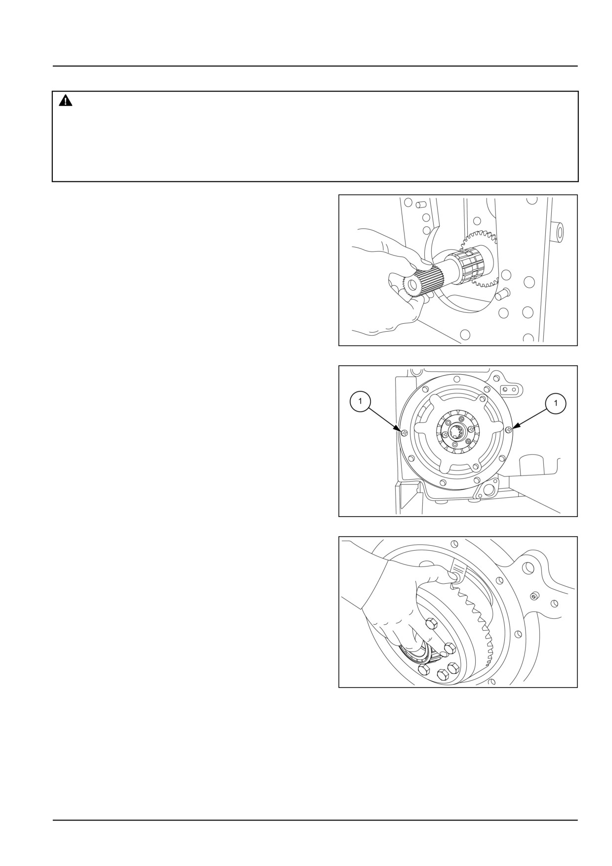
1. Remove the driven shaft, drive shaft and range shaft
before dismantling pinion shaft.
GNIL14TR04069AA
1
2.
1. To remove the crown wheel loosen set screws (1)
from the cover plate.
2. Remove crown wheel along with cover plate, retrieve
rubber ring from the housing.
GNIL14TR04070AB
2
3. Remove the crown wheel along with differential hous-
ing.
GNIL14TR04071AA
3
27.2 [27.106] / 21
Rear axle system - Rear bevel gear set and differential
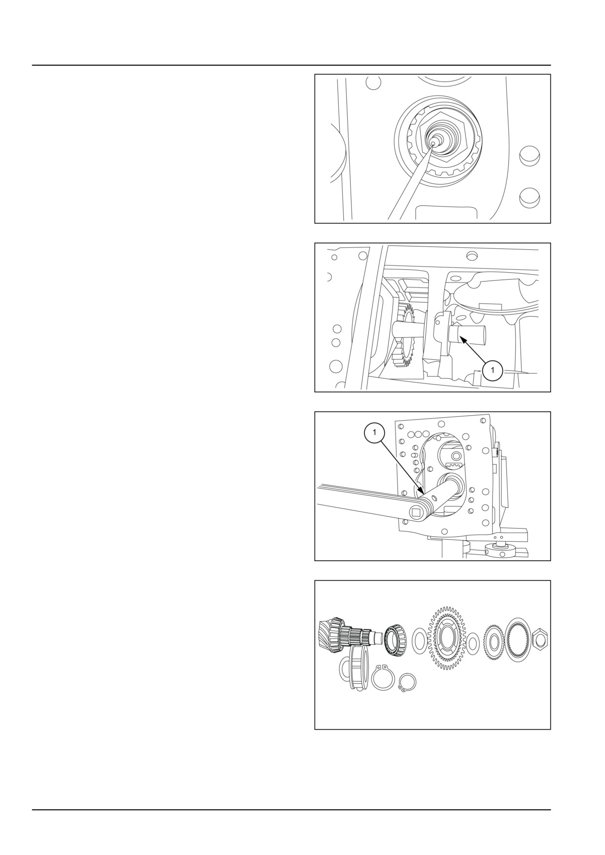
4. Open the lock of pinion locking check nut with the help
of screw driver.
GNIL14TR04072AA
4
5. Fit pinion locking tool special tool
(1) number
84261392.
GNIL14TR04073AB
5
6. Remove the pinion shaft lock nut using special tool
number 84261389.
GNIL14TR04074AB
6
7. Withdraw pinion shaft from the differential housing and
retrieve low gear, sleeve, coupling etc from the pinion
shaft.
NOTE: Keep deep cut of hub towards pinion check nut
side.
GNIL14TR04075AA
7
27.2 [27.106] / 22
Rear axle system - Rear bevel gear set and differential
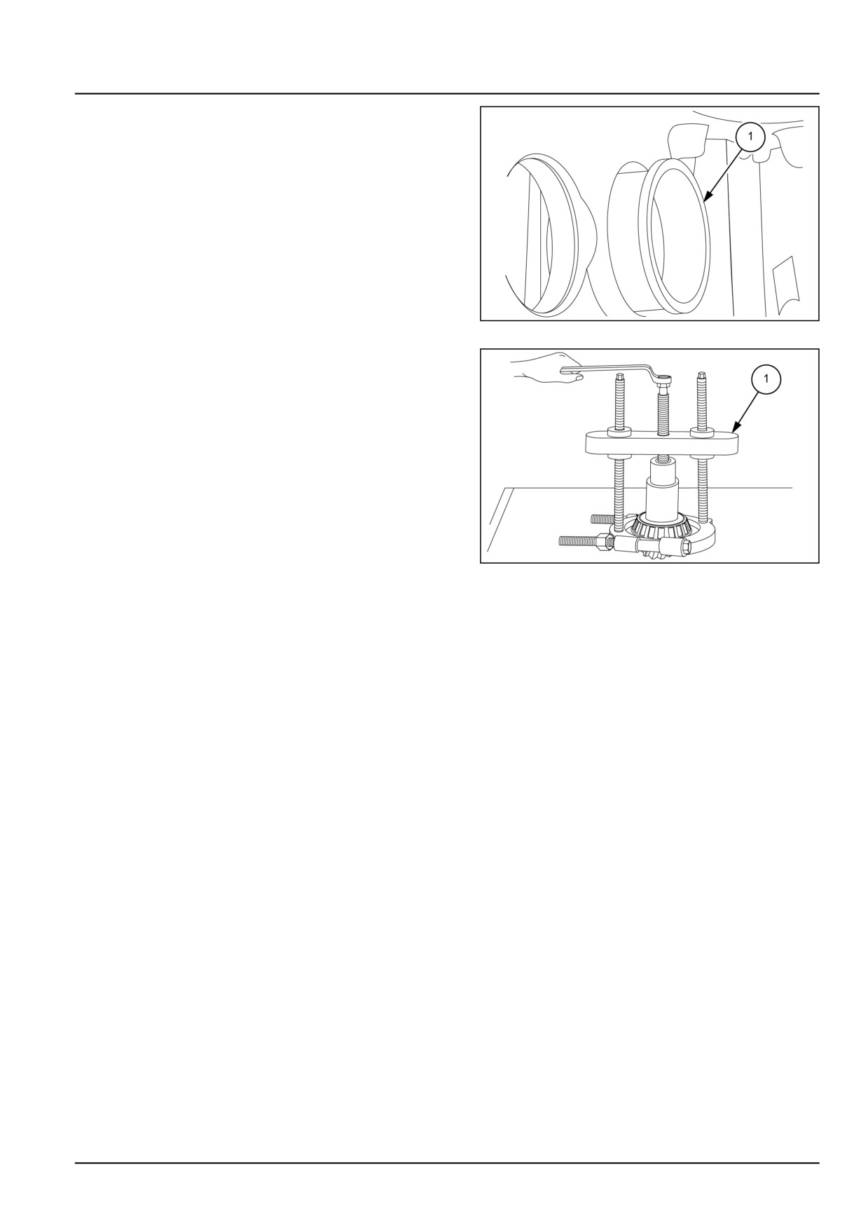
8. Remove the circlip lock of the Gama Basasa bearing to
remove bearing cone (1) from the housing.
GNIL14TR04076AB
8
9. Remove bearing from the pinion shaft using special tool
number 291051 and 291052.
GNIL14TR04077AB
9
27.2 [27.106] / 23
Rear axle system - Rear bevel gear set and differential
Bevel pinion - Install
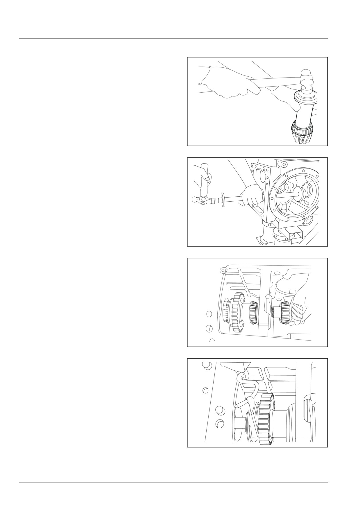
1. Install the bearing on pinion.
GNIL14TR04078AB
1
2. Fit the outer cone of Gama Bassa bearing and fit circlip
lock.
GNIL14TR04079AA
2
3. Fit pinion shaft along with hub range, sliding sleeve,
bush and low gear as shown.
NOTE: Fit small spacer keeping cuts towards pinion teeth
side, also big spacer cut towards similarly.
NOTE: Keep deep portion of low gear hub, towards pinion
check nut side. After fitment check low gear it should rotate
free.
GNIL14TR04080AA
3
4. After fitting pinion, tighten pinion check nut at 28 kgm
(203 ftlbs.) and check pinion bearing preload by wrap-
ping a cord around low gear hub with the help or spring
balance it should be 2.5 - 3.0 kgm (18.1 - 21.7 ftlbs.).
NOTE: If recommended preload not comes, hammer pin-
ion using aluminium rod lock pinion check not, and check
again.
GNIL14TR04081AA
4
27.2 [27.106] / 24
Rear axle system - Rear bevel gear set and differential
Rear bevel gear set and differential - Troubleshooting
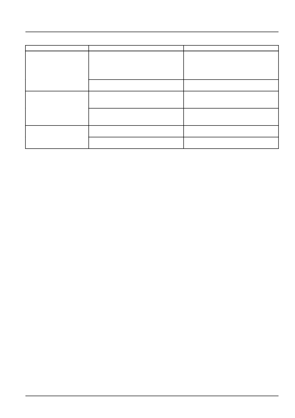
Problem
Possible Cause
Correction
Noisy rear axle when the
1. Pinion and/or ring gear bearing wrong
Remove rear axle housing and adjust pin-
tractor is moving and
adjustment
ion and ring gear bearings correctly
also when transmission
in neutral (not originating
from final drives)
2. Excess differential side gears to half-
Remove rear axle housing and replace
shaft spline backlash
damaged parts
Noisy rear axle with
1. Excess bevel pinion to ring gear back-
Remove rear axle housing and adjust bevel
tractor under load and
lash
pinion and ring gear bearings correctly
upon release
2. Fault or defective inner components
Remove rear axle housing, replace worn
parts and adjust differential gear backlash
correctly
Noisy rear axle with
1. Insufficient pinion and/or ring gear bear-
Remove rear axle housing and adjust bevel
overheating
ing backlash
pinion and ring gear bearings correctly
2. Insufficient bevel pinion to ring gear
Remove rear axle housing and adjust ring
tooth backlash
gear bearings correctly
27.2 [27.106] / 25
Index
Rear axle system - 27
Rear bevel gear set and differential - 106
Bevel pinion - Install
24
Bevel pinion - Remove
21
Differential - Assemble
18
Differential - Backlash
19
Differential - Disassemble
14
Differential - Inspect
17
Rear bevel gear set and differential - General specification
3
Rear bevel gear set and differential - Install
12
Rear bevel gear set and differential - Remove
7
Rear bevel gear set and differential - Sealing
4
Rear bevel gear set and differential - Sectional view
6
Rear bevel gear set and differential - Special tools
4
Rear bevel gear set and differential - Torque
3
Rear bevel gear set and differential - Troubleshooting
25
27.2 [27.106] / 26
Rear axle system - 27
Planetary and final drives - 120
Workmaster™ 50
Workmaster™ 60
Workmaster™ 70
27.3 [27.120] / 1
Contents
Rear axle system - 27
Planetary and final drives - 120
TECHNICAL DATA
Planetary and final drives
General specification
3
FUNCTIONAL DATA
Final drive housing
Sectional view
4
SERVICE
Final drive housing
Disassemble
5
Assemble
12
DIAGNOSTIC
Final drive housing
Troubleshooting
13
27.3 [27.120] / 2
Rear axle system - Planetary and final drives
Planetary and final drives - General specification
Type
Epicyclic
Reduction ratio
6.550 mm (0.258 in)
27.3 [27.120] / 3
Rear axle system - Planetary and final drives
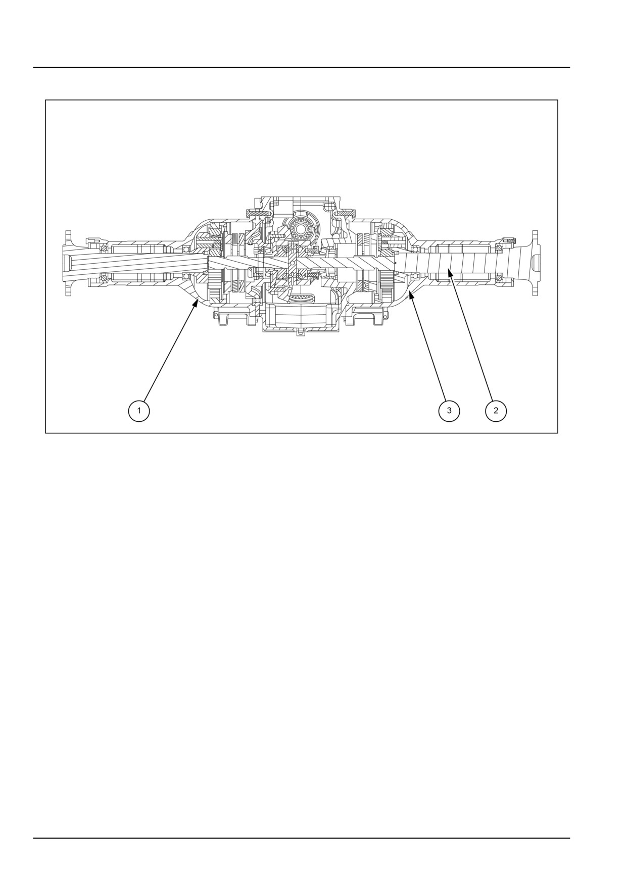
Final drive housing - Sectional view
GNIL14TR04242FB
1
Final drive
1.
Trumpet housing
3.
Planet gear
2.
Rear wheel shaft
27.3 [27.120] / 4
Rear axle system - Planetary and final drives
Final drive housing - Disassemble
WARNING
Avoid injury!
Handle all parts carefully. Do not place your hands or fingers between parts. Use Personal Protec-
tive Equipment (PPE) as indicated in this manual, including protective goggles, gloves, and safety
footwear.
Failure to comply could result in death or serious injury.
W0208A
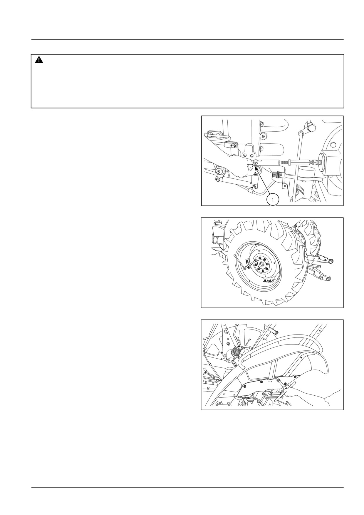
1. Remove the pin (1) and disconnect the brake linkage.
GNIL14TR00789AA
1
2. Loosen the bolts and remove the rear wheel.
GNIL14TR00866AA
2
3. Loosen the bolts and remove fender.
GNIL14TR00790AA
3
27.3 [27.120] / 5
Rear axle system - Planetary and final drives
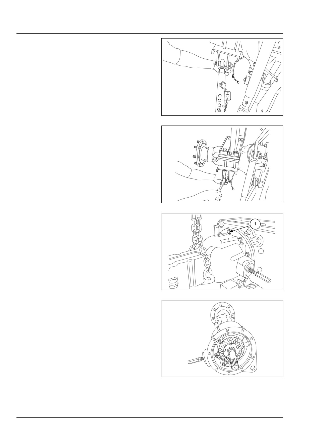
4. Remove the check chain and lower link of the three
point linkage.
GNIL14TR00864AA
4
5. Remove the ROPS (Roll Over Protective Structure).
NOTE: Use a suitable hoist.
GNIL14TR00865AA
5
6.
1. Wrap chain around final drive housing and loosen
bolts (1).
2. Remove the final drive housing.
GNIL14TR04276AB
6
7. Place the trumpet housing assembly on plane surface.
GNIL14TR04336AA
7
27.3 [27.120] / 6
Rear axle system - Planetary and final drives
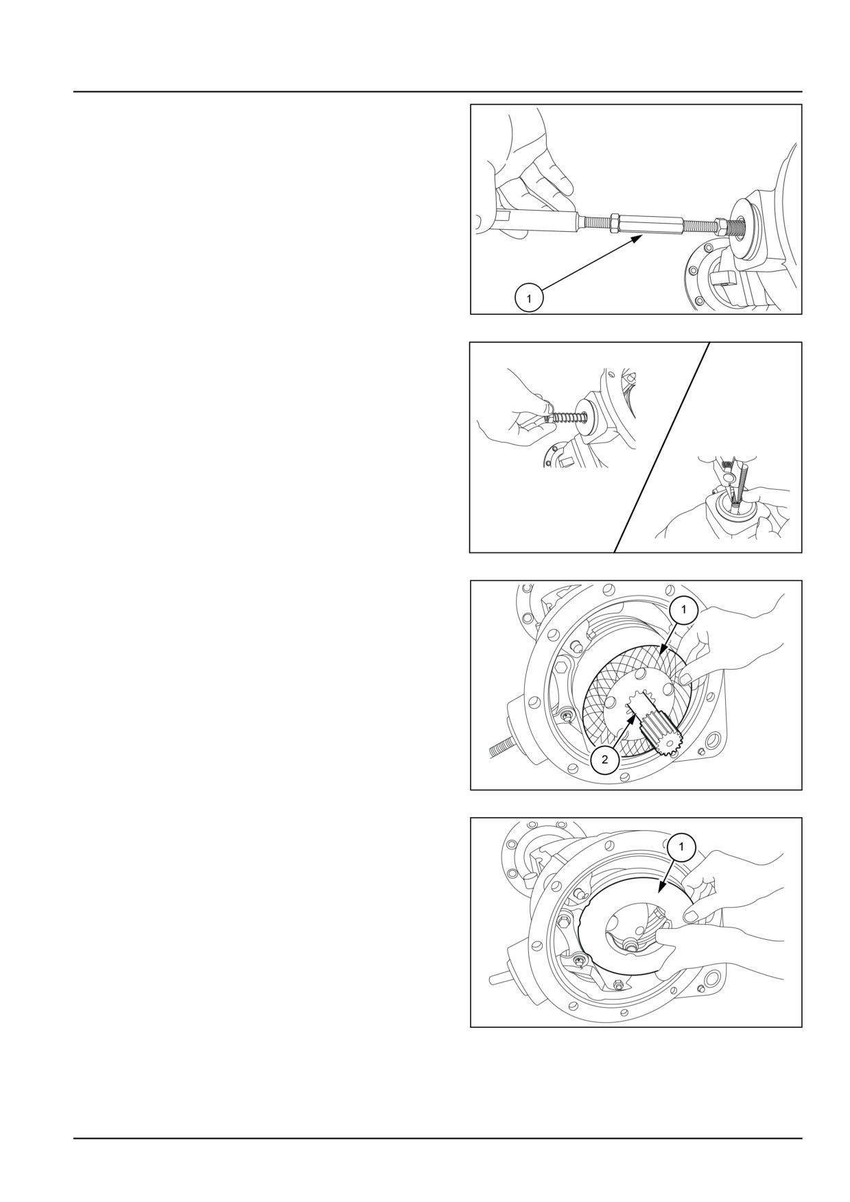
8. Remove the linkage (1).
GNIL14TR00792AA
8
9. Remove the nut and spring. Remove the circlip.
GNIL14TR00791AA
9
10. Remove brake disc (1) and shaft (2).
GNIL14TR04277AB
10
11. Remove the brake actuator assembly (1).
GNIL14TR04278AB
11
27.3 [27.120] / 7
Rear axle system - Planetary and final drives
12. Remove second brake disc.
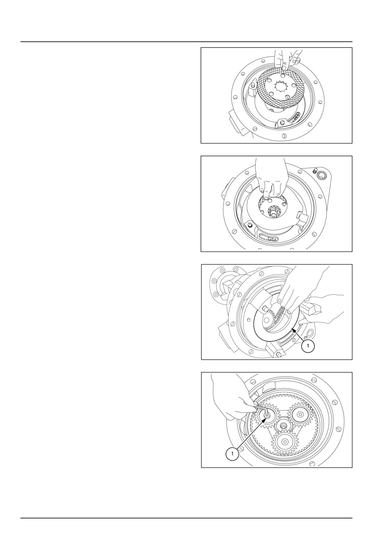
GNIL14TR00779AA
12
13. Remove intermediate plate and third brake disc.
GNIL14TR00780AA
13
14. Remove dual brake support (1) as shown.
GNIL14TR04279AB
14
15. Remove the set screw (1) holding the cover for road
wheel shaft.
GNIL14TR04280AB
15
27.3 [27.120] / 8
Rear axle system - Planetary and final drives
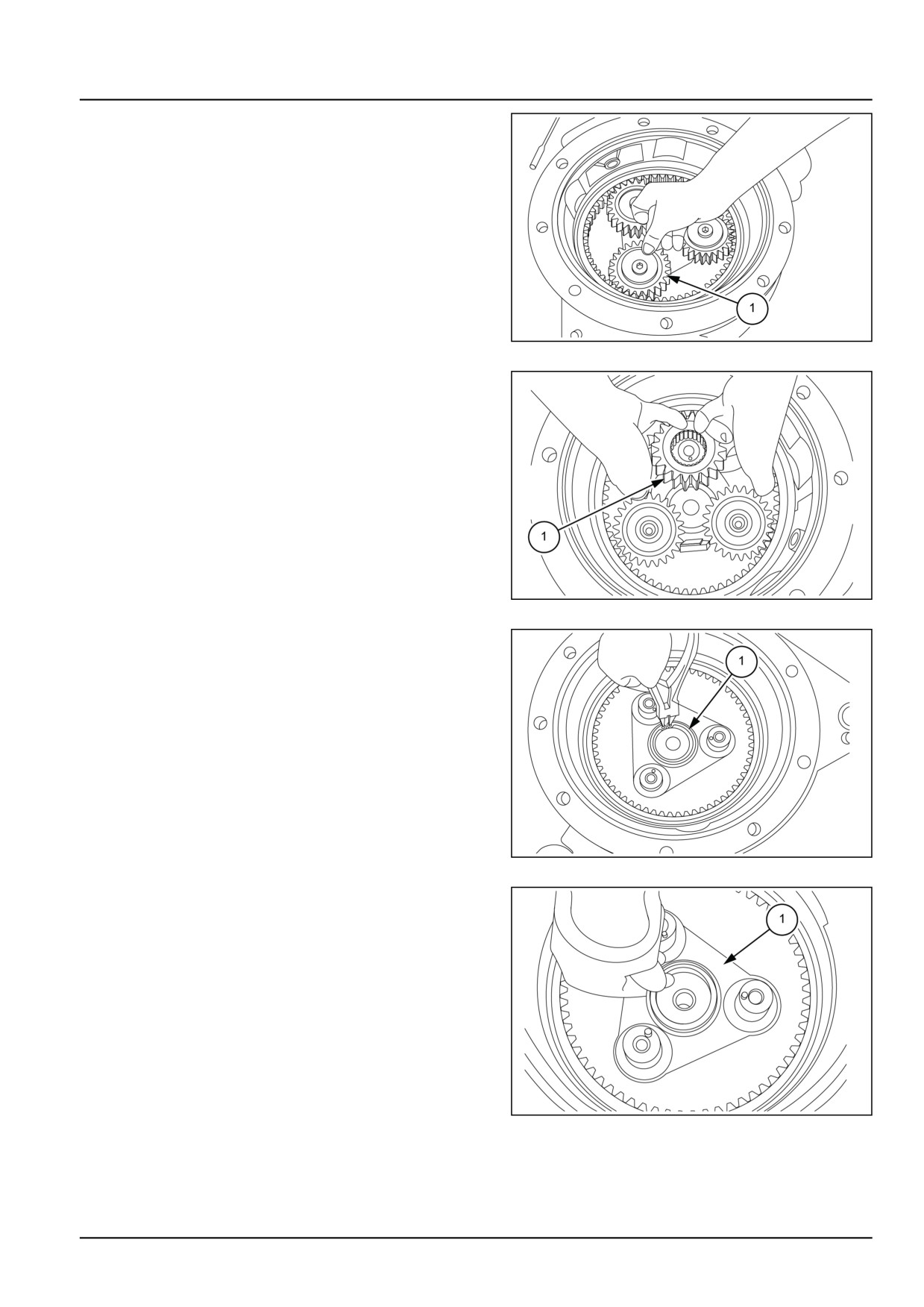
16. Remove spacers (1) planet final drive.
GNIL14TR04281AB
16
17. Remove all three planet gears along with needle bear-
ings.
GNIL14TR04282AB
17
18. Remove the circlip lock (1) of planet carrier sub as-
sembly.
GNIL14TR04283AB
18
19. Remove the spacer and shims (1).
GNIL14TR04284AB
19
27.3 [27.120] / 9
Rear axle system - Planetary and final drives
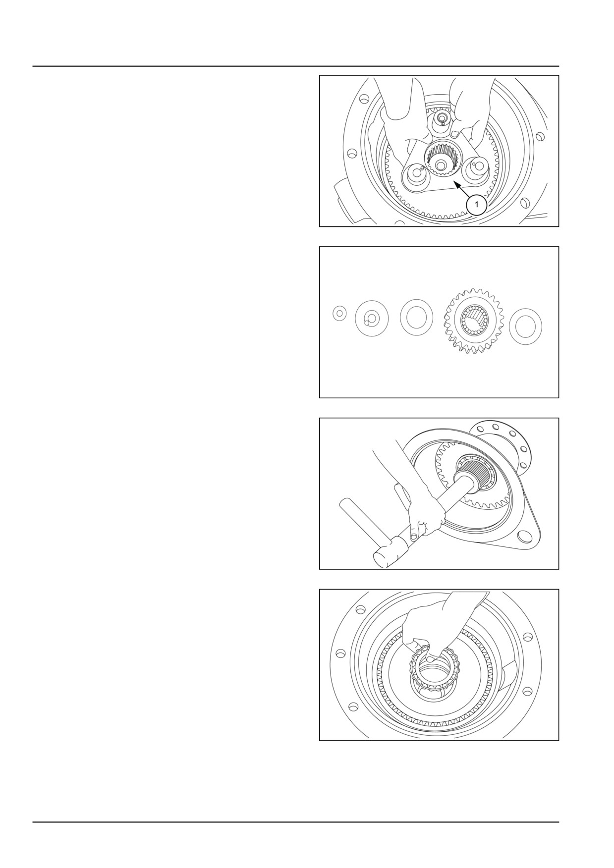
20. Remove planet carrier sub assembly (1).
GNIL14TR04285AB
20
21. Check planet gear spacers and needle bearings for
damage, replace if found worn out.
GNIL14TR04286AA
21
22. Hammer the wheel axle shaft out of the final drive
housing.
GNIL14TR04287AA
22
23. Retrieve the taper roller bearing.
NOTE: Ball bearings are fitted in low duty trumpet housing.
GNIL14TR04288AA
23
27.3 [27.120] / 10
Rear axle system - Planetary and final drives
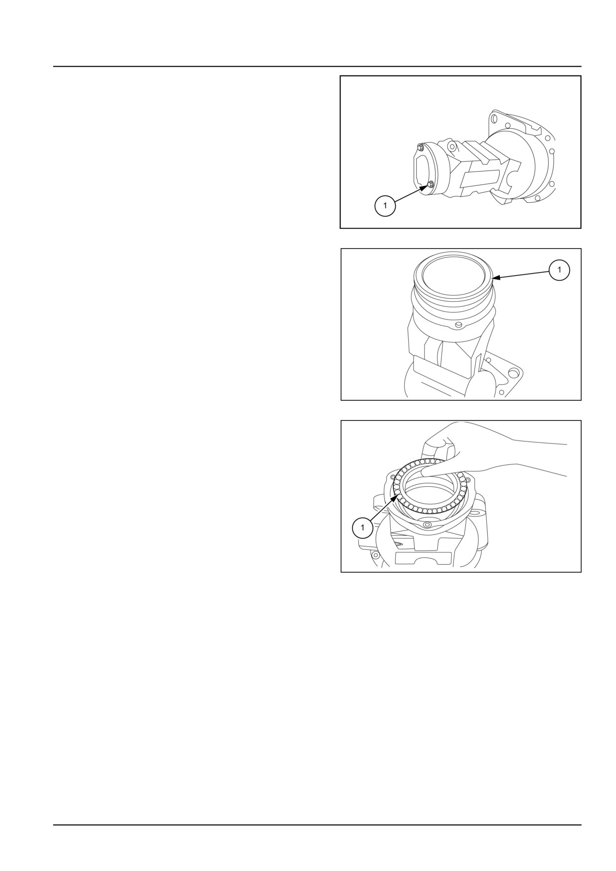
24. Loosen the three bolts of mud protection cover from
the final drive housing.
GNIL14TR04289AB
24
25. Retrieve oil seal from the housing.
GNIL14TR04290AA
25
26. Retrieve the taper roller bearing, external spacer seal
and oil seal from the trumpet.
NOTE: During assembly insert bearing spacer over bear-
ing manually in heavy duty drive line.
NOTE: Ball bearing is fitted in low duty trumpet housing.
GNIL14TR04291AB
26
27.3 [27.120] / 11
Rear axle system - Planetary and final drives
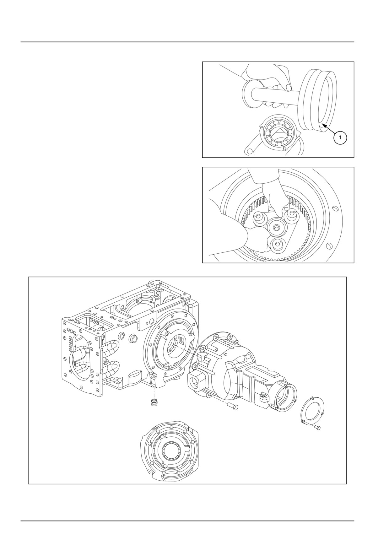
Final drive housing - Assemble
Reinstall wheel and axle shaft in final drive housing
observing the following:
• Re assembling follows the removal procedure. See
Final drive housing - Disassemble (27.120).
• Refer to figure for correct orientation of the shafts
bearings sleeves and seals.
• Check seals and replace if damaged.
• Fit final drive housing oil seal back, by using the spe-
cial tool number 84261386.
• Check planet carrier after fitting circlip lock on axle
for free play. If notice any free play remove circlip
lock and place suitable shim below the spacer, so as
GNIL14TR04292AB
1
to eliminate free play completely.
NOTE: In low duty trumpet housing bearing preload
is not required.
• Before reassembling housing and covers thoroughly
clean and de-grease mating surfaces and apply a
2.00 mm (0.08 in) bead of sealant following the pat-
tern shown in the figure.
GNIL14TR04293AA
2
GNIL14TR04294FA
3
27.3 [27.120] / 12
Rear axle system - Planetary and final drives
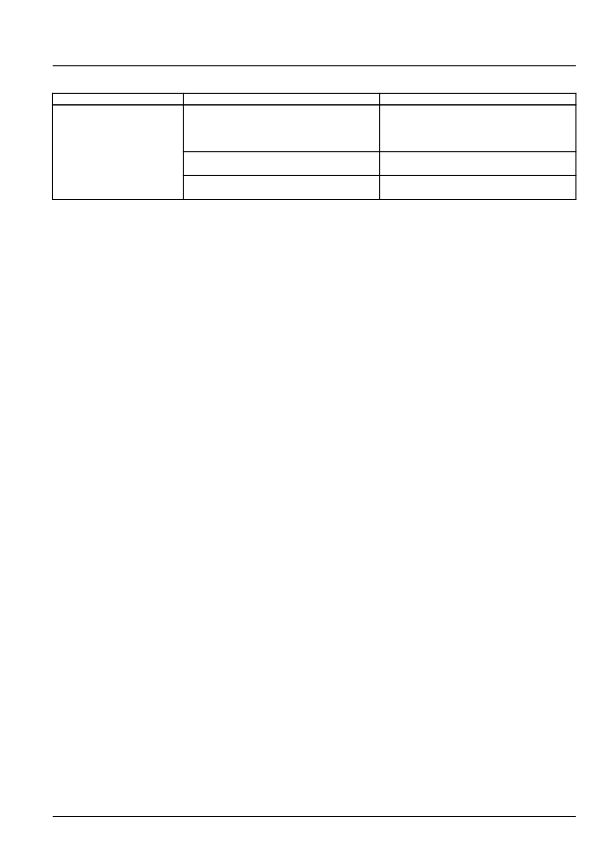
Final drive housing - Troubleshooting
Problem
Possible Cause
Correction
Noisy final drives when
1. Wheel axle shaft bearing badly adjusted
Remove final drive case and adjust bear-
the tractor is moving and
ings
also with transmission in
neutral
2. Faulty or defective inner components.
Remove final drive case and replace dam-
aged parts
3. Excess bull and pinion gear backlash
Remove final drive case and replace dam-
aged parts
27.3 [27.120] / 13
Index
Rear axle system - 27
Planetary and final drives - 120
Final drive housing - Assemble
12
Final drive housing - Disassemble
5
Final drive housing - Sectional view
4
Final drive housing - Troubleshooting
13
Planetary and final drives - General specification
3
27.3 [27.120] / 14
CNH Industrial America New Holland Site 100 Brubaker Avenue New Holland, Pennsylvania United States
17557
SERVICE - Technical Publications & Tools
PRINTED IN U.S.A.
All rights reserved. No part of the text or illustrations of this publication may be reproduced.
NEW HOLLAND policy is one of continuous improvement and the right to change prices, specification or equipment
at any time without notices is reserved.
All data given in this publication is subject to production variations. Dimensions and weight are approximate only and
the illustrations do not necessarily show products in standard condition. For exact information about any particular
product, please consult your NEW HOLLAND Dealer.
EN