New Holland Tractor Workmaster 50 / Workmaster 60 / Workmaster 70 / Tier 4B (final). SERVICE MANUAL - page 6
SERVICE MANUAL
Front axle system
Workmaster™ 50
Workmaster™ 60
Workmaster™ 70
25
Contents
Front axle system - 25
[25.100] Powered front axle
25.1
[25.102] Front bevel gear set and differential
25.2
[25.108] Final drive hub, steering knuckles, and shafts
25.3
[25.310] Final drives
25.4
[25.400] Non-powered front axle
25.5
25
Front axle system - 25
Powered front axle - 100
Workmaster™ 50
Workmaster™ 60
Workmaster™ 70
25.1 [25.100] / 1
Contents
Front axle system - 25
Powered front axle - 100
TECHNICAL DATA
Four-Wheel Drive (4WD) axle
General specification
3
Torque
5
Special tools
6
FUNCTIONAL DATA
Four-Wheel Drive (4WD) axle
Overview
8
Sectional view
9
SERVICE
Four-Wheel Drive (4WD) axle
Remove
12
Remove
15
Install
18
Disassemble
19
Inspect
25
Assemble
26
Adjust
27
Toe in adjust
30
25.1 [25.100] / 2
Front axle system - Powered front axle
Four-Wheel Drive (4WD) axle - General specification
Axle class
Class 1
Unrestricted (static) axle capacity
2400.0 kg (5291.1 lb)
Bevel gear pair - differential
Pinion-ring gear ratio
9/38 = 1:4.2
Backlash between bevel gear pair
0.15 mm (0.006 in) - 0.20 mm (0.008 in)
Bevel drive and differential
2.5 mm (0.0984 in) - 2.55 mm (0.1004 in) -
2.6 mm (0.1024 in) - 2.65 mm (0.1043 in) -
2.7 mm (0.1063 in) - 2.75 mm (0.1083 in) -
2.8 mm (0.1102 in) - 2.85 mm (0.1122 in) -
2.9 mm (0.1142 in) - 2.95 mm (0.1161 in) -
3.00 mm (0.1181 in) - 3.05 mm (0.1201 in) -
3.10 mm (0.1220 in) - 3.15 mm (0.1240 in)
- 3.2 mm (0.1260 in) - 3.25 mm (0.1280 in)
- 3.3 mm (0.1299 in) - 3.35 mm (0.1319 in)
- 3.4 mm (0.1339 in) - 3.4 mm (0.1339 in) -
•
Thickness of pinion bearing adjustment shim
3.4 mm (0.1339 in) - 3.4 mm (0.1339 in) -
3.4 mm (0.1339 in) - 3.4 mm (0.1339 in) -
3.4 mm (0.1339 in) - 3.4 mm (0.1339 in) -
3.4 mm (0.1339 in) - 3.4 mm (0.1339 in) -
3.4 mm (0.1339 in) - 3.4 mm (0.1339 in) -
3.4 mm (0.1339 in) - 3.4 mm (0.1339 in) - 3.4 mm
(0.1339 in) - 3.45 mm (0.1358 in) - 3.5 mm
(0.1378 in) - 3.55 mm (0.1398 in) - 3.6 mm
(0.1417 in) - 3.65 mm (0.1437 in) - 3.7 mm
(0.1457 in)
2.5 mm (0.0984 in) - 2.6 mm (0.1024 in) -
2.7 mm (0.1063 in) - 2.8 mm (0.1102 in) - 2.9 mm
(0.1142 in) - 3.00 mm (0.1181 in) - 3.1 mm
•
Thickness of crown wheel position adjustment shim
(0.1220 in) - 3.2 mm (0.1260 in) - 3.3 mm
(0.1299 in) - 3.4 mm (0.1339 in) - 3.5 mm
(0.1378 in) - 3.6 mm (0.1417 in) - 3.7 mm
(0.1457 in)
•
Clearance between sides of planet and side pinion teeth
0.15 mm (0.006 in)
•
Thickness of planet pinion thrust washers
1.470 mm (0.058 in) - 1.530 mm (0.060 in)
•
Thickness of side gear thrust washers
1.50 mm (0.059 in) to 1.60 mm (0.063 in)
•
Diameter of cross pin for planet pinions
21.939 mm (0.8637 in) - 21.960 mm (0.8646 in)
•
Side diameter cross pin bore diameter
22.040 mm (0.8677 in) to 22.061 mm (0.8685 in)
•
Clearance between cross pin and bores
0.80 mm (0.0315 in) - 0.122 mm (0.0048 in)
•
Diameter of outer axle shafts and corresponding bushings
37.961 mm (1.4945 in) - 38.000 mm (1.4961 in)
•
Inside diameter of installed bushings
38.080 mm (1.4992 in) - 38.119 mm (1.5007 in)
•
Clearance between axle shafts and bushings
0.080 mm (0.0031 in) - 0.158 mm (0.0062 in)
•
Type of differential lock
LSD
Axle Shafts and Steering Knuckles
• Diameter of outer axle shafts and corresponding bushings
29.914 mm (0.0031 in) - 29.935 mm (1.1785 in)
• Inside diameter of installed front bushings
30.050 mm (1.1831 in) - 30.105 mm (1.1852 in)
• Clearance between pin and bushings
0.115 mm (0.0045 in) - 0.191 mm (0.0075 in)
• Interference fit between bushings and respective bores
0.064 mm (0.0025 in) - 0.129 mm (0.0051 in)
0.10 mm (0.0039 in) - 0.15 mm (0.0059 in) -
• Thickness of steering knuckle bearing adjuster plates
0.20 mm (0.0079 in) - 0.25 mm (0.0098 in) -
0.30 mm (0.0118 in)
Planetary final drives
15 mm (0.5906 in):( 19 mm (0.7480 in)+ 54 mm
• Reduction ratio
(2.1260 in)) = 1:4.87
• Driven gear thrust washer thickness
0.77 mm (0.0303 in) - 0.83 mm (0.0327 in)
Axle pivot
25.1 [25.100] / 3
Front axle system - Powered front axle
• Pivoting angle/oscillation (on either side)
11 °
• Center pivot and support end float
0.3 mm (0.0118 in) - 1.1 mm (0.0433 in)
• Maximum wear clearance
2 mm (0.0787 in)
• Center pivot diameter
52.652 mm (2.0729 in) - 52.671 mm (2.0737 in)
• Center pivot front bushing fitted
52.720 mm (2.0756 in) - 52.790 mm (2.0783 in)
• Center pivot working clearance in bushing
0.049 mm (0.0019 in) - 0.138 mm (2.0783 in)
• Rear bevel pinion carrier spigot
99.040 mm (3.8992 in) - 99.72 mm (3.9260 in)
• Rear bushing fitted
99.146 mm (3.9034 in) - 99.221 mm (3.9063 in)
• Spigot fitted clearance in bushing
0.074 mm (0.0029 in) - 0.181 mm (0.0071 in)
Axle front and rear thrust washer thickness
4.95 mm (0.1949 in) - 5.00 mm (0.1969 in)
Turning radius
• Turning radius with brakes
4200.0 mm (165.4 in)
• Turning radius without brakes
4850.0 mm (190.9 in)
Turnaround diameter
• Turnaround diameter with brakes
8720.0 mm (343.3 in)
• Turnaround diameter without brakes
10020.0 mm (394.5 in)
Maximum axle steering angle
62 °
Camber angle
1°
Caster angle
2°
Tire sizes
9.5 x 24
• Front 4WD
R4 12.5x18
14.9 x 28
• Rear 4WD
R4 18.4x24
25.1 [25.100] / 4
Front axle system - Powered front axle
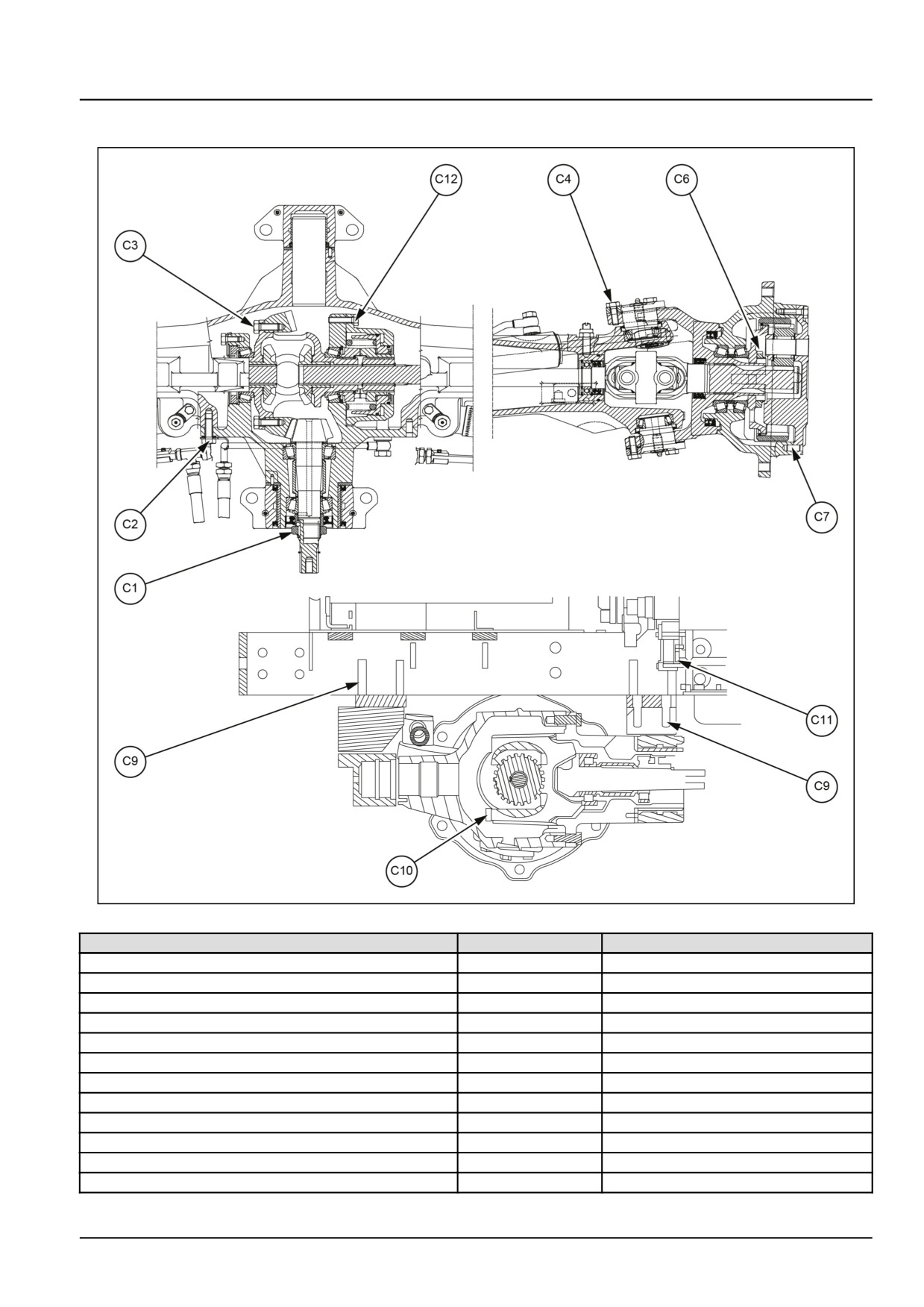
Four-Wheel Drive (4WD) axle - Torque
GNIL14TR04345GB
1
Description
Thread size
Torque
Lock ring, bevel pinion (C1)
M35 x 1.5
294 N·m (217 lb ft)
Bolt, differential case to axle casing (C2)
M12 x 1.25
113 N·m (83 lb ft)
Bolt, ring gear to differential case (C3)
M12 x 1.25
127 N·m (94 lb ft)
Bolt, king pin (C4)
M10 x 1.25
64 N·m (47 lb ft)
Steering knuckle bolt (C5)
M10 x 1.25
64 N·m (47 lb ft)
Wheel hub bearings lock nut (C6)
M45 x 1.5
392 N·m (289 lb ft)
Bolt, planetary final drive housing (C7)
M10 x 1.25
64 N·m (47 lb ft)
Bolt, wheel disc to hub (C8)
M16 x 1.5
193 N·m (142 lb ft)
Nut for rim to disc securing bolt
M16 x 1.5
193 N·m (142 lb ft)
Front axle front and rear pivot support bolt (C9)
M18 x 1.5
280 N·m (207 lb ft)
Differential cage support cap bolt (C10)
M12 x 1.25
113 N·m (83 lb ft)
Front axle support to engine retaining bolt (C11)
M18 x 1.5
314 N·m (232 lb ft)
25.1 [25.100] / 5
Front axle system - Powered front axle
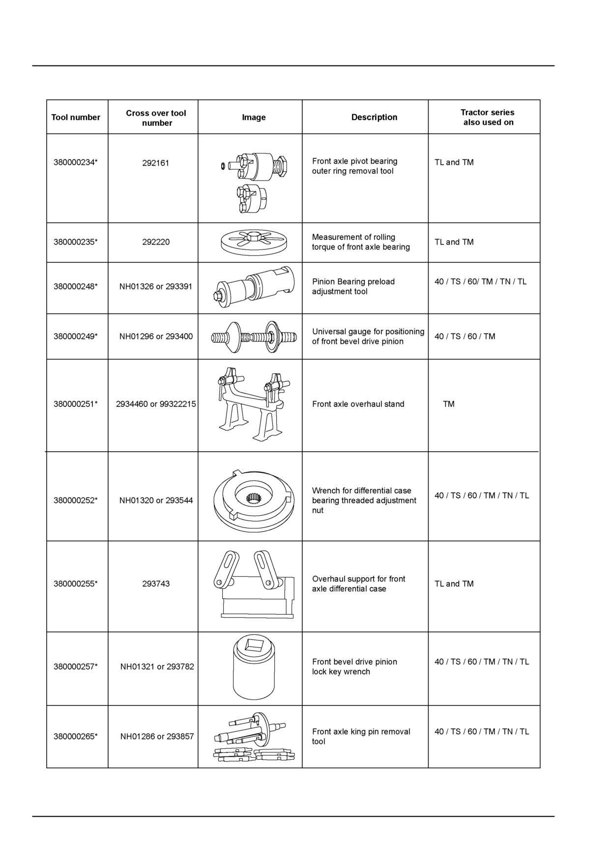
Four-Wheel Drive (4WD) axle - Special tools
GNIL14TR04346HA
1
25.1 [25.100] / 6
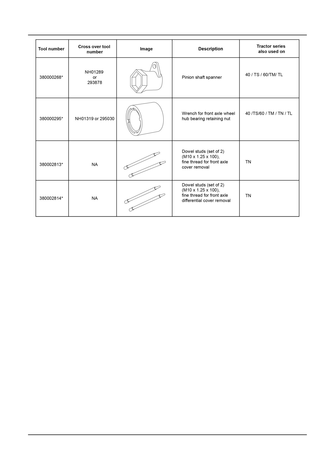
Front axle system - Powered front axle
GNIL14TR04347HA
2
25.1 [25.100] / 7
Front axle system - Powered front axle
Four-Wheel Drive (4WD) axle - Overview
The tractor has a centrally pivoting front axle with the pivot and the drive shaft coaxial with the longitudinal axis of the
tractor. The drive shaft has no universal joints.
The differential has two planet pinions; drive is transmitted to lateral epicyclic final drive units (installed on the wheel
hubs) through universal joints which require no maintenance.
Front to rear axle ratio
NOTE: On tractors equipped with FWD (Front Wheel Drive) the front to rear axle ratio is critical and must be main-
tained for safe and efficient use of the tractor. This ratio applies to all available tire options. Following is a list of
problems that may occur if the front to rear axle ratio is not maintained:
• Engine will lug down or stall when operating on hard surfaces.
• The front wheel drive lever will not remain in the engaged position, or is difficult to disengage.
• Failure of the drive line gears.
• Failure of the front axle, ring and pinion gears.
• Premature tire wear.
25.1 [25.100] / 8
Front axle system - Powered front axle
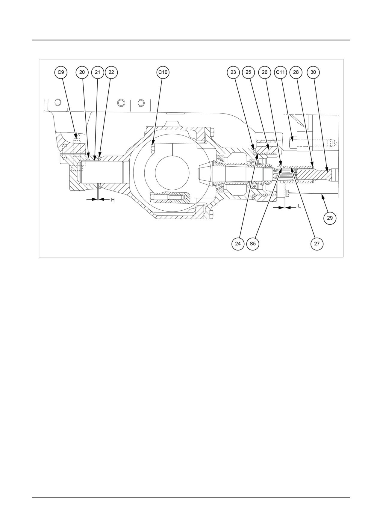
Four-Wheel Drive (4WD) axle - Sectional view
GNIL14TR04350FB
1
H
1.000 mm (0.039 in)
23
Rear thrust washer
L
1.000 - 1.500 mm (0.039 - 0.059 in)
24.
Rear bushing
S5
Sleeve position shim
25.
Rear axle pivot support
C9
Axle pivot support bolt
26.
Retaining rings
C10
Differential bearing cap bolt
27.
Front splined sleeve
C11
Bolt securing front axle support to engine
28.
Retaining rings
20.
Front axle pivot support
29.
Drive shaft guard
21.
Front bushing
30.
Drive shaft
22.
Front thrust washer
25.1 [25.100] / 9
Front axle system - Powered front axle
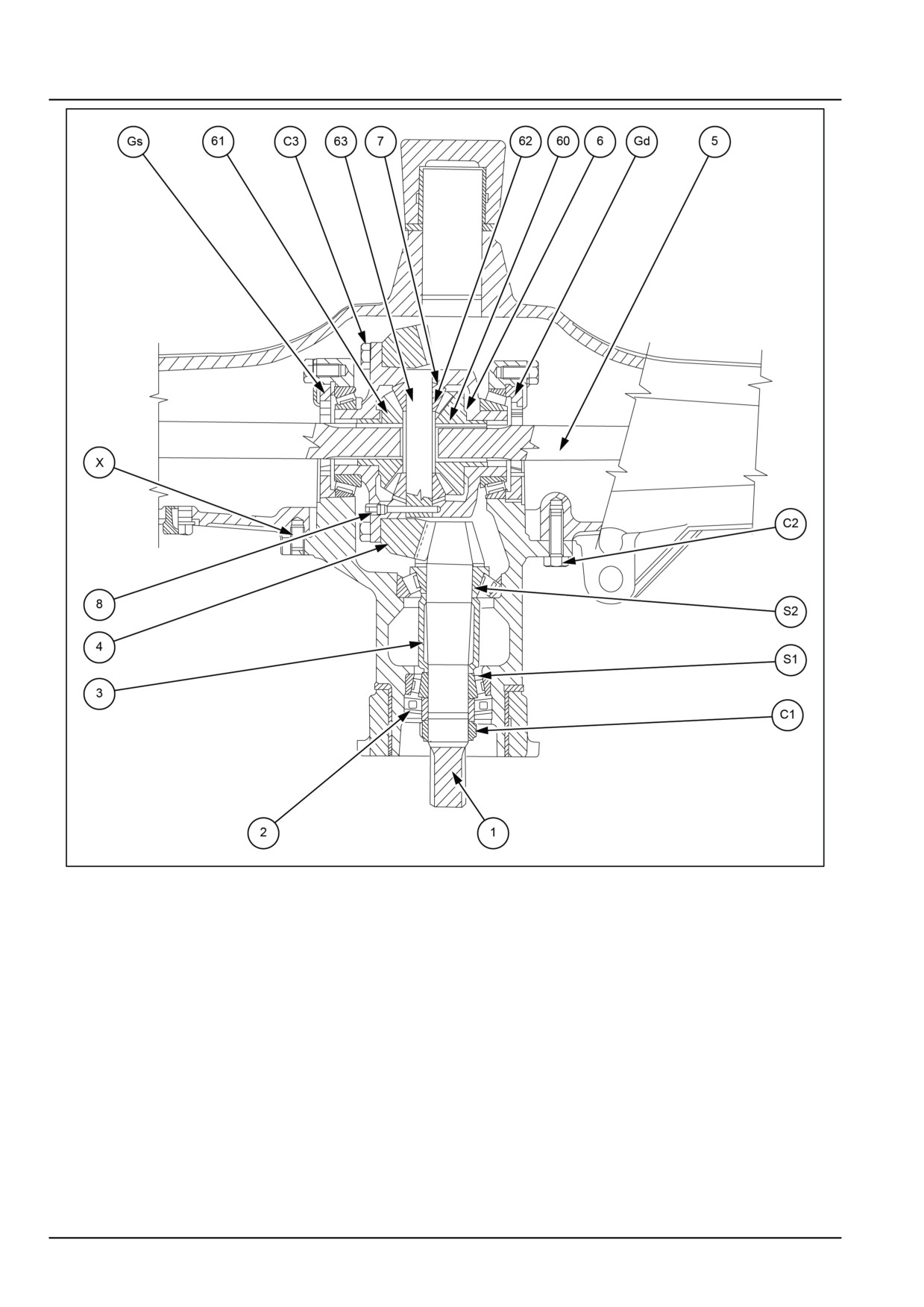
GNIL14TR04351GB
2
X
0.500 - 1.000 mm (0.020 - 0.039 in)
4.
Ring gear
S1
Bevel pinion bearing shim
5.
Axle shaft with universal joint
S2
Bevel pinion position shim
6.
Side gear washers
C1
Bevel pinion bearing lock ring
7.
Differential pinion washers
C2
Differential carrier bolt
8.
Differential pinion journal bolt
C3
Ring gear bolt
60.
Side gear
Gd,
Right-hand side and left-hand side differential
61.
Side gear
Gs
bearing lock ring
1.
Bevel pinion
62.
Differential pinion
2.
Seal
63.
Differential pinion journal
3.
Bevel pinion bearing spacer
25.1 [25.100] / 10
Front axle system - Powered front axle
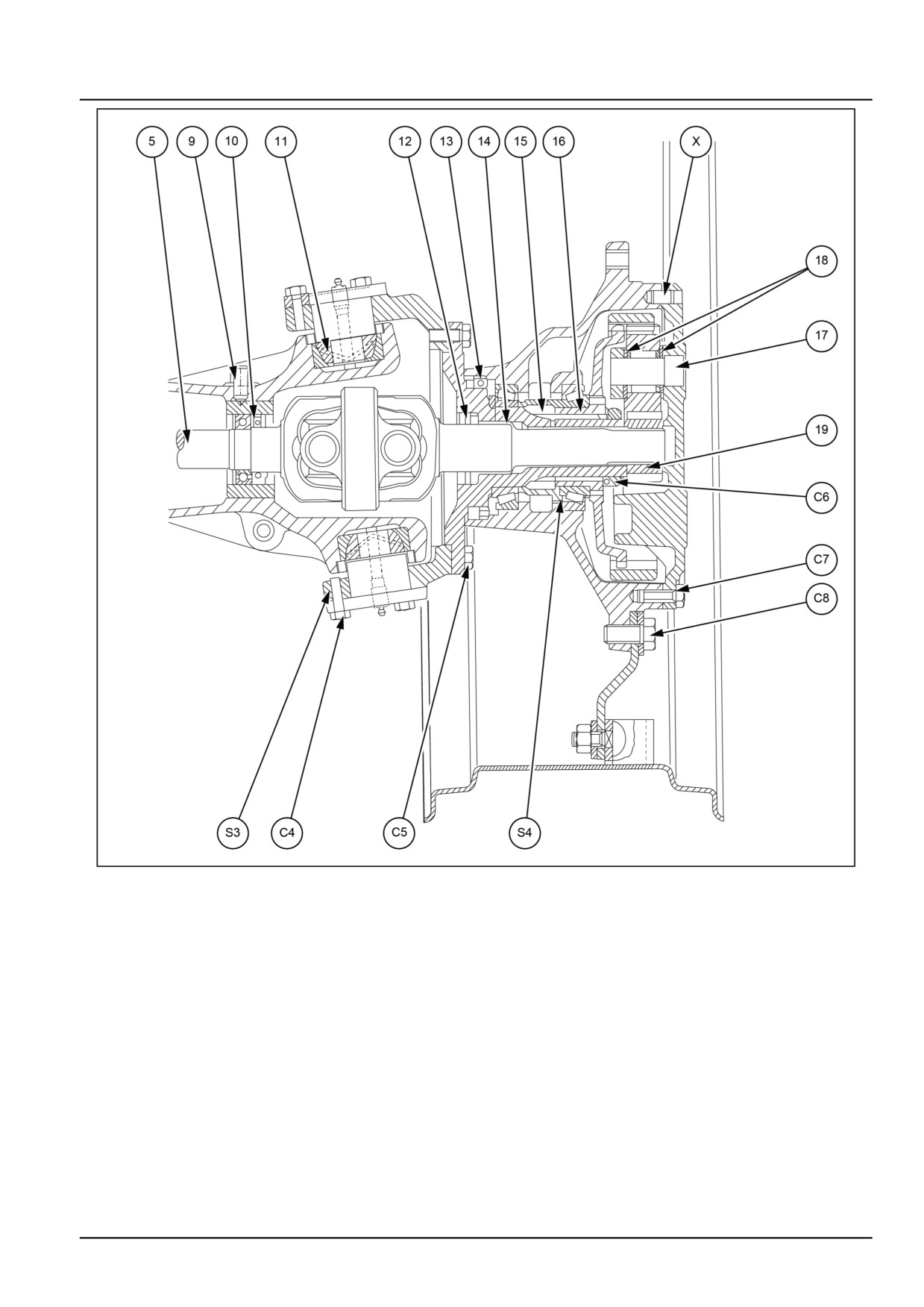
GNIL14TR04352GB
3
S3
King pin bearing shim
11.
King pin bearing
S4
Wheel hub bearing shims
12.
Seal
C4
King pin bearing bolt
13.
Seal
C5
Steering knuckle bolt
14.
Axle shaft bushing
C6
Wheel hub bearing lock ring
15
Spacer
C7
Final drive housing bolt
16.
Thrust washers
C8
Wheel hub bolt
17.
Planet wheel journals
9.
Bearing carrier bolt
18.
Planet wheel shims
10.
Seal
19.
Sun gear
25.1 [25.100] / 11
Front axle system - Powered front axle
Four-Wheel Drive (4WD) axle - Remove
WARNING
Heavy objects!
Lift and handle all heavy components using lifting equipment with adequate capacity. Always support
units or parts with suitable slings or hooks. Make sure the work area is clear of all bystanders.
Failure to comply could result in death or serious injury.
W0398A
NOTE: The front axle assembly can be removed from the tractor either with or without previously removing the drive
shaft. The description below refers to removal of the front axle with the drive shaft installed on the tractor.
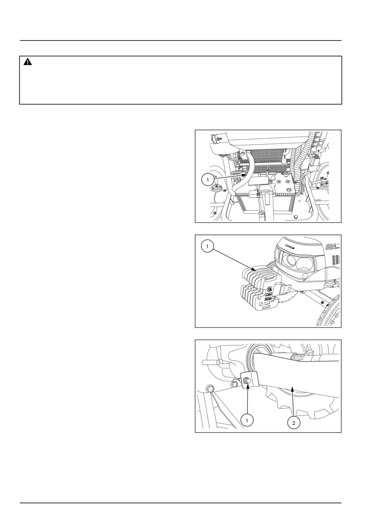
1. Disconnect the negative battery terminal (1).
GNIL14TR00784AA
1
2. Remove the front weights (1).
GNIL14TR00756AA
2
3. Remove the bolts (1), and remove the drive shaft
guards (2).
GNIL14TR00858AA
3
25.1 [25.100] / 12
Front axle system - Powered front axle
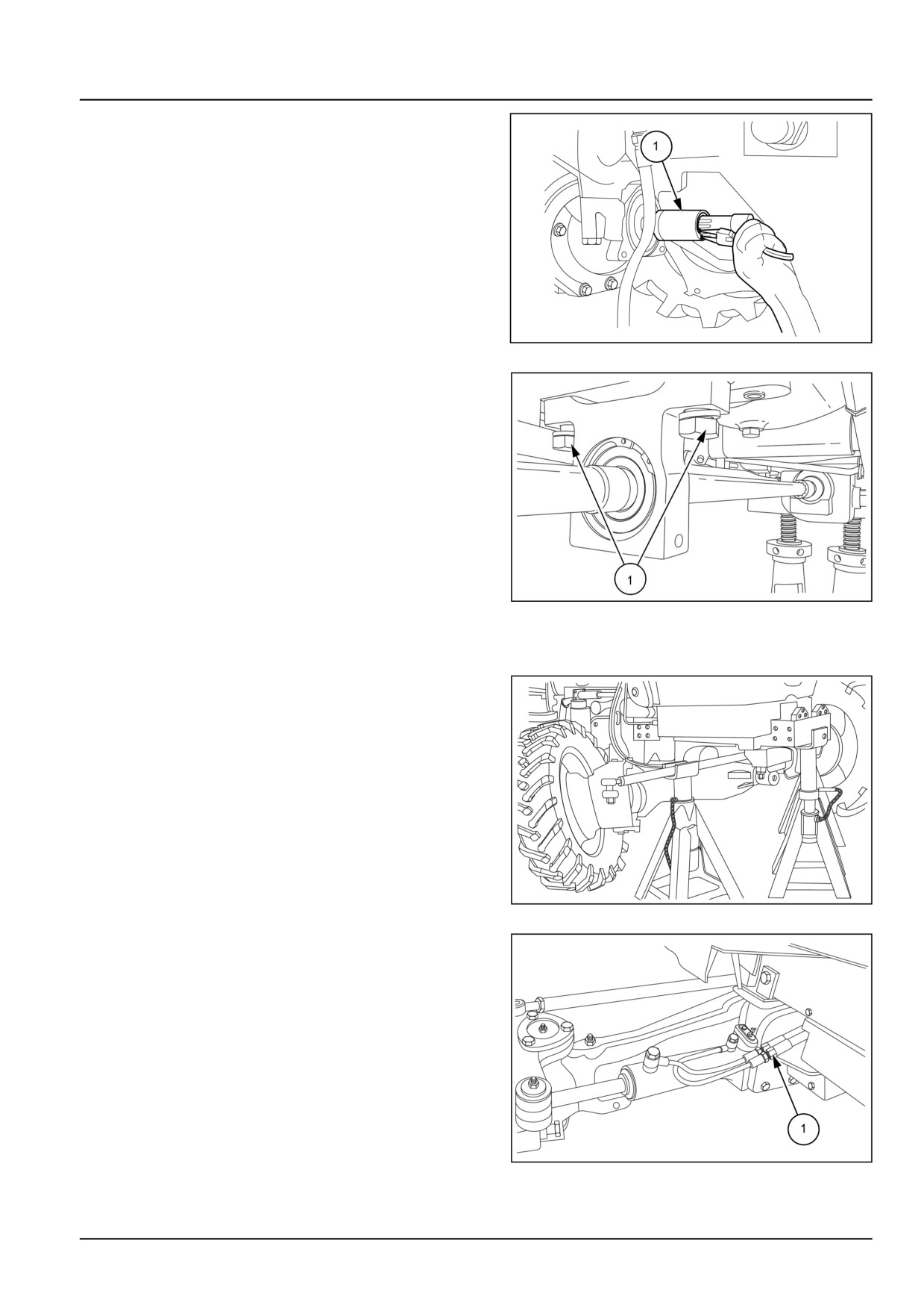
4. Remove the snap ring (1) from the front and rear of the
drive shaft.
GNIL14TR04359AB
4
5. Remove the bolts (1) from the drive shaft support bear-
ing.
6. Remove the drive shaft from the front axle input shaft
and drop box output shaft by sliding the two couplers
onto the drive shaft.
GNIL14TR00859AA
5
7. Attach nylon slings around the front axle and attach
them to a hoist.
8. Lift the tractor with the hoist and place a stand under
the lower portion of the front axle.
GNIL14TR04361AA
6
9. Remove the power steering hoses (1) from the power
steering tubes.
GNIL14TR04362AB
7
25.1 [25.100] / 13
Front axle system - Powered front axle
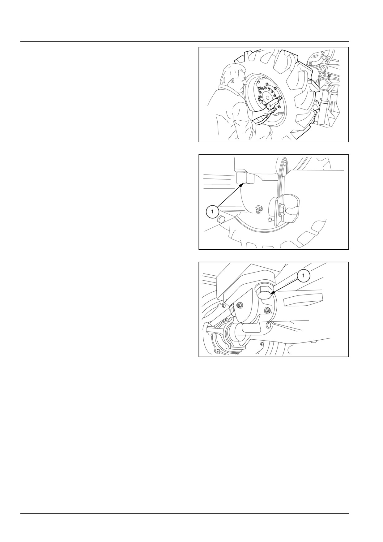
10. Remove the front wheels.
GNIL14TR04363AA
8
11. Remove the front axle rear support retaining bolts (1).
GNIL14TR04364AB
9
12. Remove the front axle front support retaining bolts (1).
13. Using a hoist and nylon cables (one for each side)
detach the front axle from the tractor.
GNIL14TR04365AB
10
25.1 [25.100] / 14
Front axle system - Powered front axle
Four-Wheel Drive (4WD) axle - Remove
WARNING
Heavy objects!
Lift and handle all heavy components using lifting equipment with adequate capacity. Always support
units or parts with suitable slings or hooks. Make sure the work area is clear of all bystanders.
Failure to comply could result in death or serious injury.
W0398A
Proceed as follows:
NOTE: The front axle assembly can be removed from the
tractor either with or without previously removing the drive
shaft. The description below refers to removal of the front
axle with the drive shaft installed on the tractor.
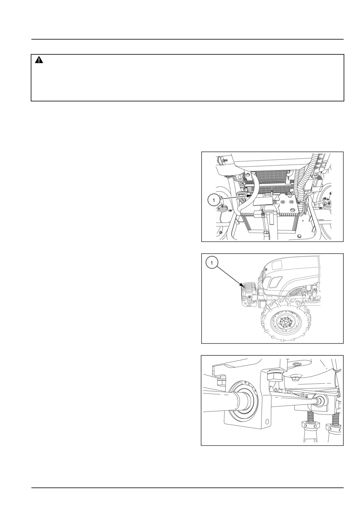
1. Disconnect the negative battery lead (1).
GNIL14TR00784AA
1
2. remove the front weights (1).
GNIL14TR00829AA
2
3. Remove the bolts (1), and remove the drive shaft
guards (2).
GNIL14TR00859AA
3
25.1 [25.100] / 15
Front axle system - Powered front axle
4. Remove the snap ring (1) from the front and rear of the
drive shaft.
GNIL14TR04359AB
4
5. Remove the bolts (1) from the drive shaft support bear-
ing.
6. Remove the drive shaft from the front axle input shaft
and drop box output shaft by sliding the two couplers
onto the drive shaft.
GNIL14TR00859AA
5
7. Attach nylon slings around the front axle and attach
them to a hoist.
8. Lift the tractor with the hoist and place a stand under
the lower portion of the front axle.
GNIL14TR04361AA
6
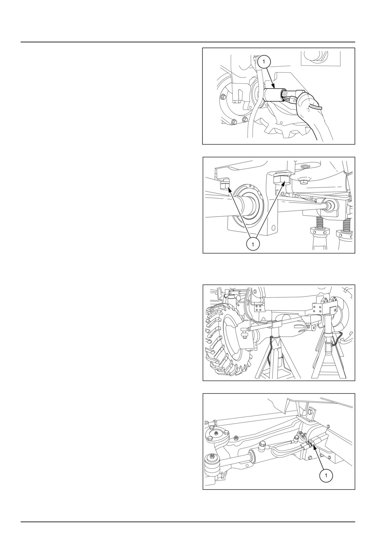
9. Remove the power steering hoses (1) from the power
steering tubes.
GNIL14TR04362AB
7
25.1 [25.100] / 16
Front axle system - Powered front axle
10. Remove the front wheels.
GNIL14TR04363AA
8
11. Remove the front axle rear support retaining bolts (1).
GNIL14TR04364AB
9
12.
1. Remove the front axle front support retaining bolts
(1).
2. Using a hoist and nylon cables (one for each side)
detach the front axle from the tractor.
GNIL14TR04365AB
10
25.1 [25.100] / 17
Front axle system - Powered front axle
Four-Wheel Drive (4WD) axle - Install
CAUTION
Pinch hazard!
Always use suitable tools to align mating parts.
DO NOT use your hand or fingers.
Failure to comply could result in minor or mod-
erate injury.
C0044A
1. Refit the front axle following the instructions below.
• Install the axle and bolt the front and rear supports
in position.
• Reconnect the power steering hoses.
• Install the front wheels.
• Raise the front of the tractor using the hoist.
• Remove the fixed stand.
• Detach the nylon cables.
• Reconnect the drive shaft and install the drive shaft
guard.
• Attach a nylon cable to the front weights, lift, install
to the tractor and secure with the locking screws.
• Reconnect the negative battery lead.
• See the Four-Wheel Drive (4WD) axle - Torque
(25.100).
25.1 [25.100] / 18

Front axle system - Powered front axle
Four-Wheel Drive (4WD) axle - Disassemble
WARNING
Avoid injury!
Handle all parts carefully. Do not place your
hands or fingers between parts. Use Personal
Protective Equipment (PPE) as indicated in this
manual, including protective goggles, gloves,
and safety footwear.
Failure to comply could result in death or seri-
ous injury.
W0208A
GNIL14TR04367AA
1
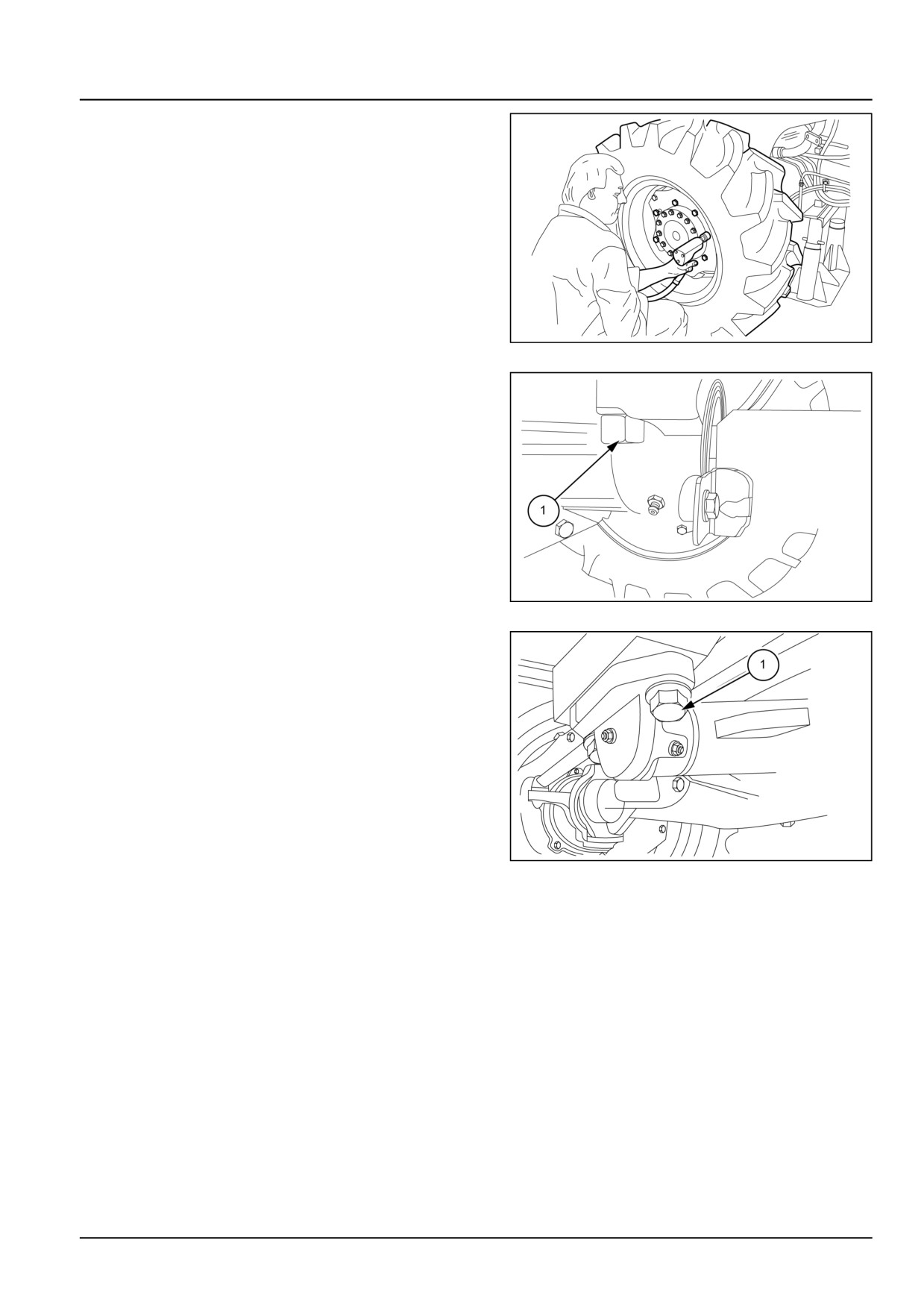
1. Remove plug (1) and drain the oil from the axle cas-
ing.
GNIL14TR04368AB
2
2. To drain the final drive oil, remove plug (1) on the
left-hand final drive casing.
3. Repeat the same operation on the right-hand side
casing.
GNIL14TR04369AB
3
4. Remove the rear support (1) off the front axle.
5. Remove the front support and the thrust washer.
GNIL14TR04370AB
4
25.1 [25.100] / 19
Front axle system - Powered front axle
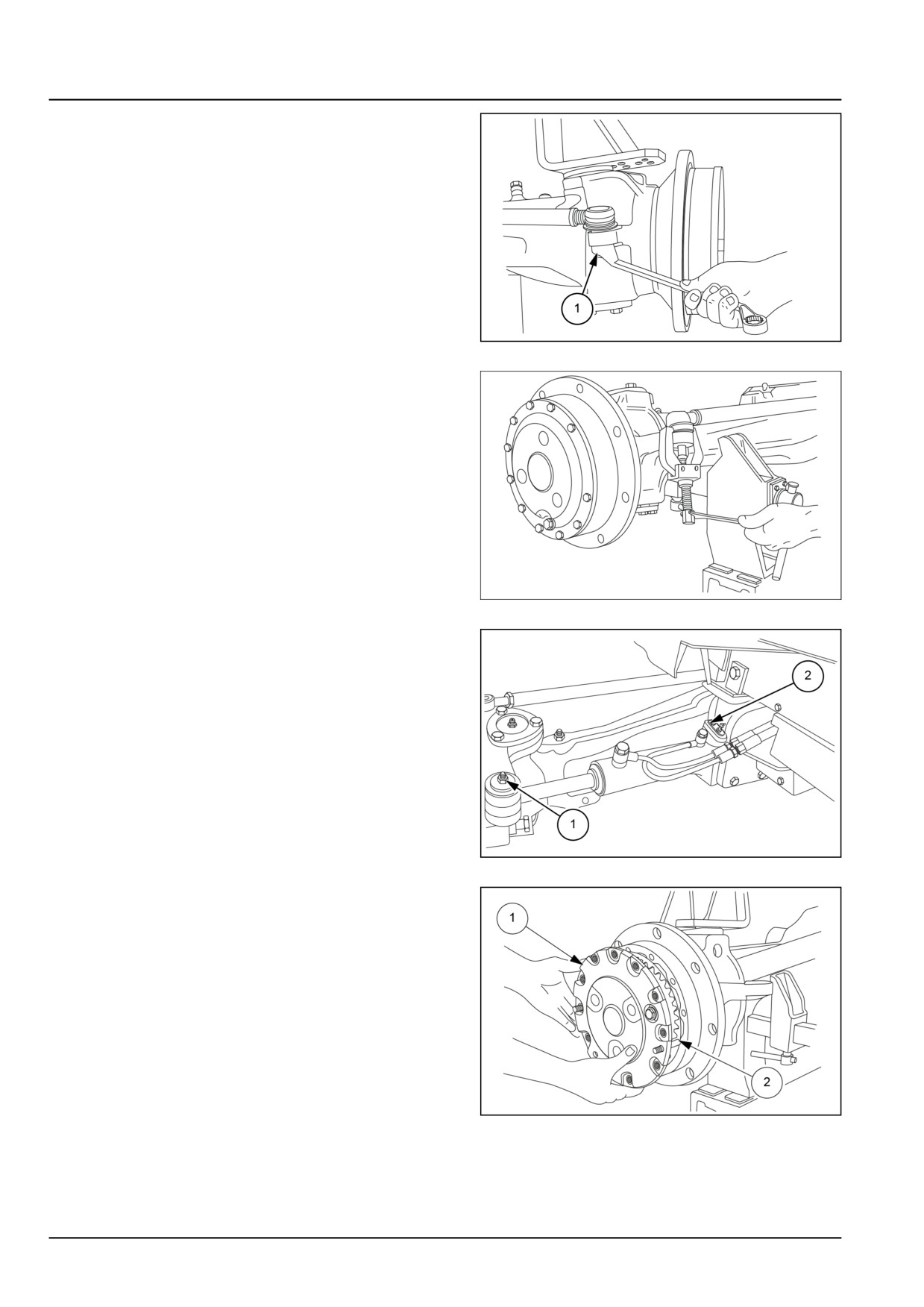
6. Remove the tie rod retaining nuts (1).
GNIL14TR04371AB
5
7. Using a removal tool, remove the tie rod ends from
their bores in the stub axle housing.
GNIL14TR04372AA
6
8. Remove the snap ring from the bottom of the cylinder
rod pivot pin (1)
9. Remove the pin retaining bolt (2) from the pin. Re-
move the pins and detach the cylinder.
GNIL14TR04373AB
7
10. Unscrew the retaining bolts off the left-hand final
drive casing cover (1).
11. Screw in the two M10 x 100 dowels tool no
380002813
(2).
12. Using a slide hammer puller screwed into the oil
drain plug.
13. Detach the cover (1) from the casing.
GNIL14TR04374AB
8
25.1 [25.100] / 20
Front axle system - Powered front axle
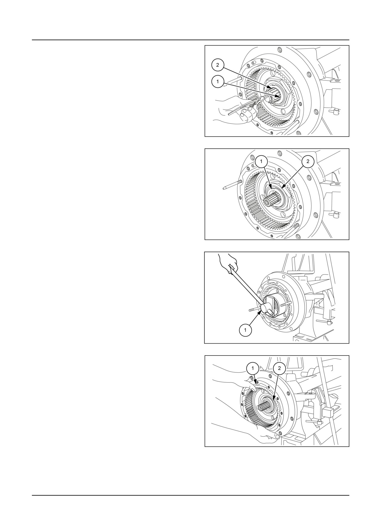
14. Remove the snap ring (1).
15. Remove the driving gear (2).
GNIL14TR04375AB
9
16. Remove the staking (1) on the wheel hub bearing
lock ring (2).
GNIL14TR04377AB
10
17. Remove the wheel hub bearing lock ring using tool
no 380000295 (1).
GNIL14TR04378AB
11
18. Remove the wheel hub (1) with the ring gear (2).
GNIL14TR04379AB
12
25.1 [25.100] / 21
Front axle system - Powered front axle
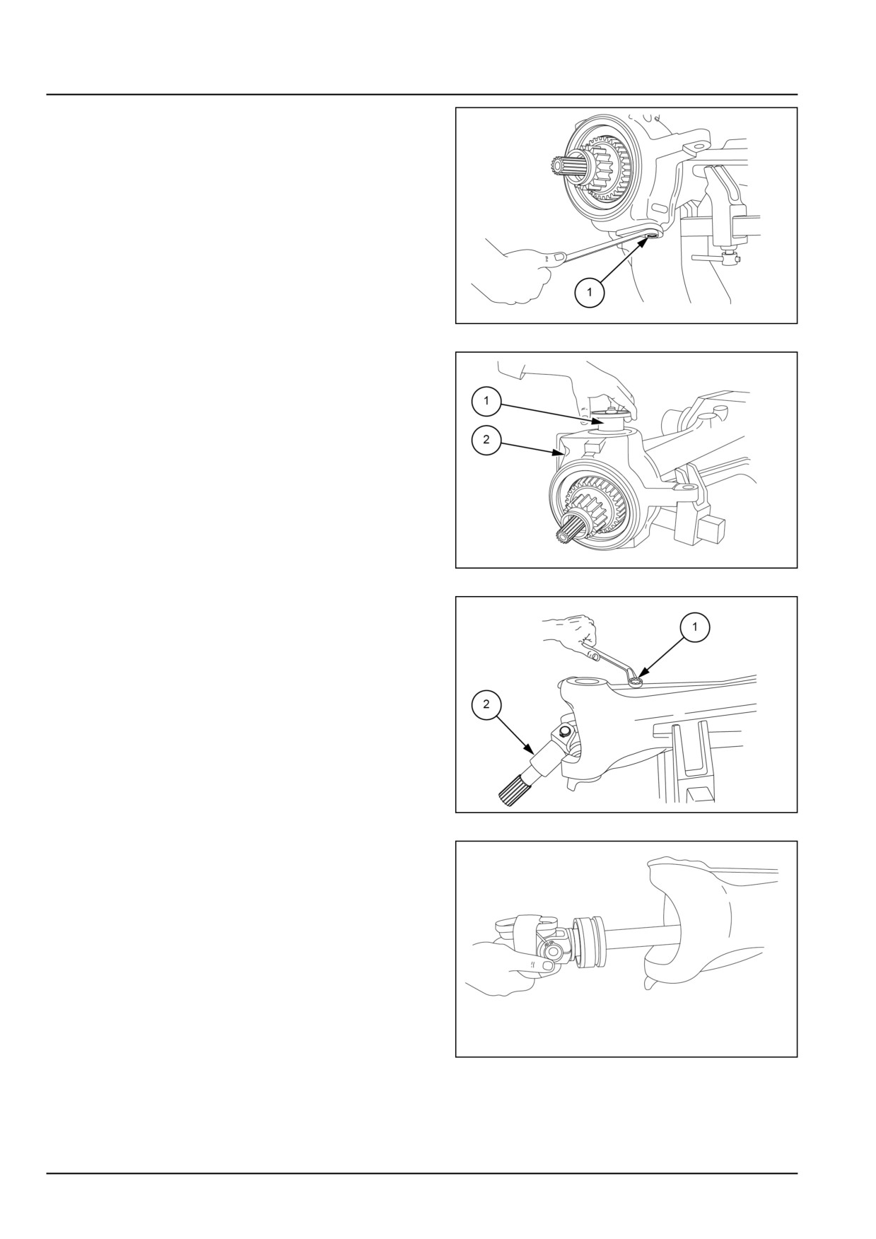
19. Remove the retaining bolts (1) of the lower pivot pin
of the stub axle housing.
20. Remove the lower pivot pin and the relative adjust-
ment shims.
GNIL14TR04380AB
13
21. Remove the retaining bolts of the upper pivot pin.
22. Remove the upper pivot pin (1).
23. Remove the stub axle housing (2).
GNIL14TR04381AB
14
24. Remove the retaining bolt (1) of the axle shaft (2).
GNIL14TR04382AB
15
25. Using a pry bar, pull the axle shaft out of the casing.
26. To disassemble the right-hand final drive unit, re-
peat the above steps [Invalid Reference] to [Invalid
Reference].
GNIL14TR04383AA
16
25.1 [25.100] / 22
Front axle system - Powered front axle
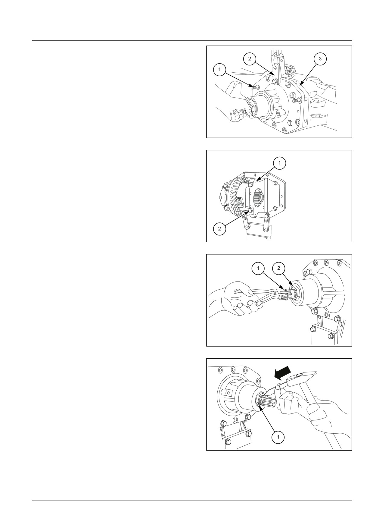
27. Remove the bolts fixing the bevel drive-differential
support to the axle casing.
28. Screw in the M12 x 100 dowels, tool no 380002814
(1).
29. Remove the remaining bolts and separate the bevel
drive-differential support from the axle casing.
30. Attach a chain (2) to the support and take up the
weight with the hoist.
31. Remove the bevel drive-differential support (3) from
the axle casing.
GNIL14TR04384AB
17
32. Remove the two bolts (1) from the two ring gear
differential support caps (2).
33. Remove the crown wheel-differential assembly
from the housing.
GNIL14TR04385AB
18
34. Remove the snap ring (1) from the splined shaft (2).
GNIL14TR04386AB
19
35. Straighten the locking tab on the splined shaft lock
nut (1).
GNIL14TR04387AB
20
25.1 [25.100] / 23
Front axle system - Powered front axle
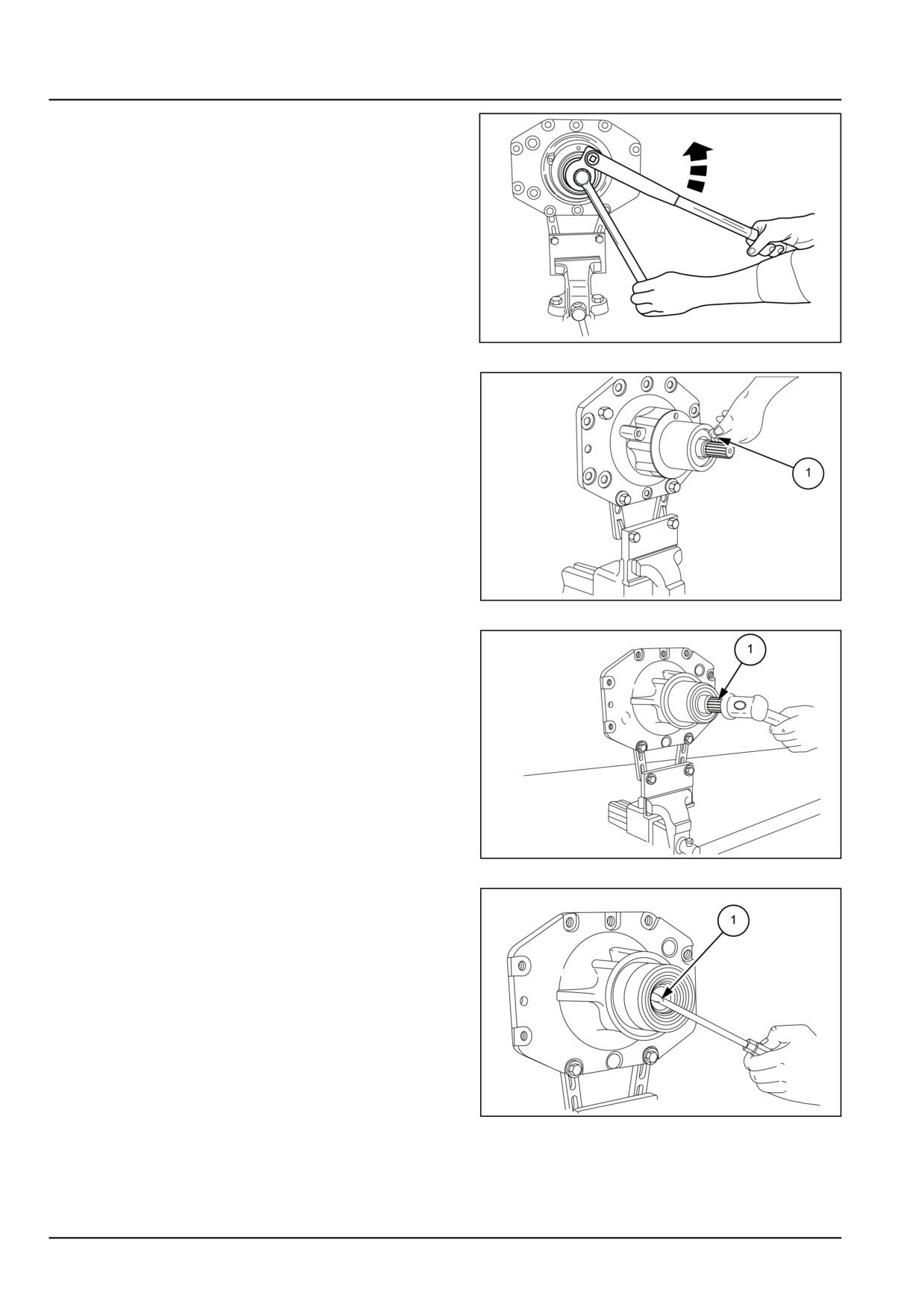
36. Remove the nut using wrench, tool no 380000268
(1), while holding the bevel drive pinion shaft against
rotation with wrench, tool no 380000257.
GNIL14TR04388AB
21
37. Remove the splined shaft detent ball (1).
GNIL14TR04389AB
22
38. Remove the bevel drive pinion shaft (1) from the
rear of the casing and remove the spacer, the adjust-
ment shims and the bearing.
NOTE: Observe the quantity and the size of the shims re-
moved from the pinion shaft.
GNIL14TR04390AB
23
39. Using a screwdriver, remove the dust seal, seal ring
(1) and rear bearing.
GNIL14TR04391AB
24
25.1 [25.100] / 24
Front axle system - Powered front axle
Four-Wheel Drive (4WD) axle - Inspect
1. Wash all parts in a suitable solvent and allow to air dry.
2. Inspect the gears for excess wear or damage. Replace
as necessary.
3. Check all the bearings for wear or roughness. Rotate
the bearings by hand and replace if necessary.
4. Inspect the axle shafts and pinion shaft for wear or
damage. Replace if necessary.
5. Inspect the front axle housing for any damage. Replace
if necessary.
25.1 [25.100] / 25
Front axle system - Powered front axle
Four-Wheel Drive (4WD) axle - Assemble
1.
Reassemble the front axle. Adhere to the following
instructions:
•
See Four-Wheel Drive
(4WD) axle
- Torque
(25.100).
•
Install the rear bearing, the seal, the dust seal, the
adjustment shims, the spacer and the bevel drive
pinion shaft complete with front bearing.
•
Position the detent ball, screw in the bevel drive pin-
ion lock nut and secure in position by staking. Finally,
replace the snap ring.
•
Install the ring gear differential assembly, the support
caps and tighten the relative bolts.
•
Install the bevel drive-differential housing on the front
axle casing.
•
Install the axle shaft and relative bolt.
•
Install the stub axle, the adjustment shims, the upper
and lower pivot pins.
•
Install the wheel hub, the ring gear of the final drive
unit and the lock ring and tighten to the prescribed
torque value, while simultaneously turning the wheel
hub to ensure that the bearings are correctly seated.
•
Install the securing and stop snap rings, the driving
gear and the cover of the final drive unit.
•
Install the pins, washers, spacers and steering cylin-
ders.
•
Install the track rod, the front and rear supports and
the oil drain plugs.
25.1 [25.100] / 26
Front axle system - Powered front axle
Four-Wheel Drive (4WD) axle - Adjust
Adjustment of the ring gear bearings and checking the backlash between the pinion and
ring gear
Proceed as follows.
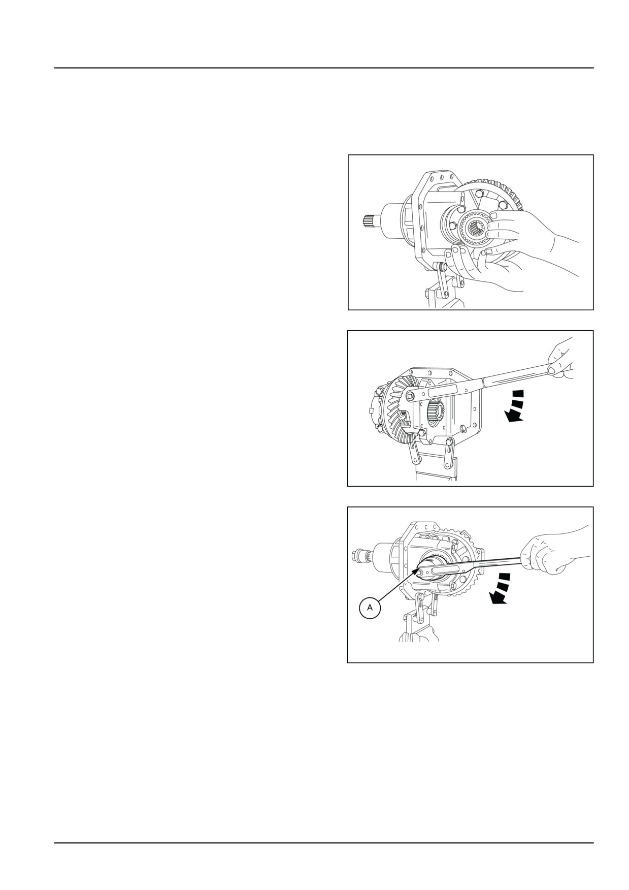
1. Install the differential assembly complete with ring gear
and inner ring gear bearing rings in the bevel drive/
differential housing.
GNIL14TR04392AA
1
2. Insert the outer bearing rings in the differential housing.
Install the differential support caps. Torque the bolts to
59 N·m (44 lb ft), then loosen and re-tighten to a torque
of 20 N·m (15 lb ft).
GNIL14TR04399AB
2
3. With the bearings lubricated, rotate the ring gear and
at the same time tighten the threaded adjustment ring
using wrench, tool no 380000252 (A) to a torque of 39 -
59 N·m (29 - 44 lb ft) to take up the axial play between
the components.
GNIL14TR04393AB
3
25.1 [25.100] / 27
Front axle system - Powered front axle
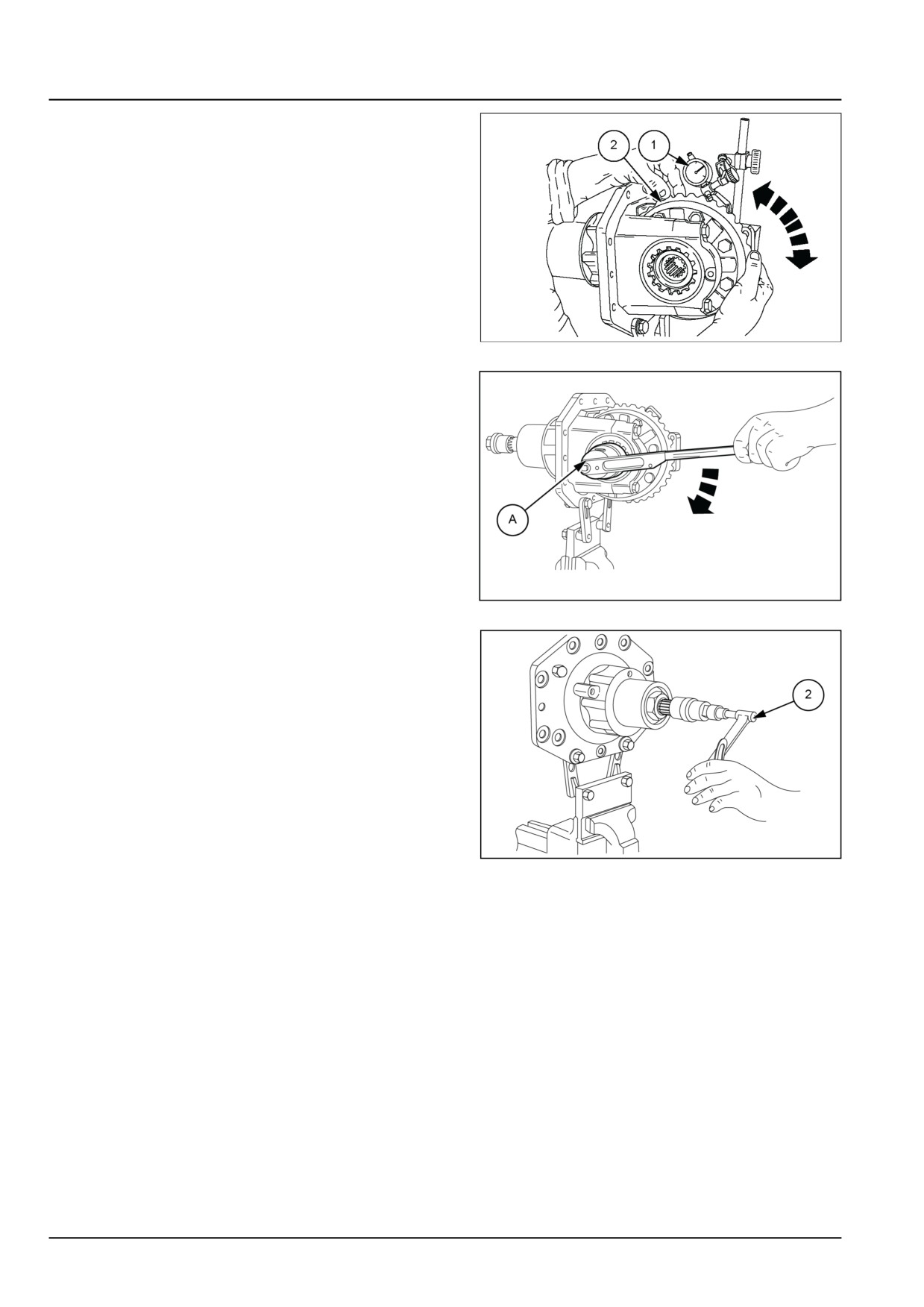
4. Measure the backlash between pinion and ring gear,
using a dial gauge (1) perpendicular to the outer edge
of a tooth on the ring gear (2).
5. Repeat the measurement in two other positions 120°
apart and compare the average of the three values
(Gm) with the prescribed normal backlash specifica-
tion of 0.18 mm (0.007 in) - 0.23 mm (0.009 in) aver-
age value 0.20 mm (0.008 in).
If the measured backlash exceeds the prescribed
value, adjust the threaded adjustment rings by screw-
ing one of the rings in and the other out by the same
amount to correct the axial preload and thus obtain the
prescribed backlash.
NDIL14TR00427AB
4
6. With a dial gauge positioned perpendicular to the out-
side edge of one of the ring gear teeth, check that the
backlash between the pinion and ring gear is within
the tolerance limits of 0.18 mm (0.007 in) - 0.23 mm
(0.009 in).
GNIL14TR04393AB
5
7. Using a wrench, tool number 380000252 (A) turn the
threaded adjustment ring and check, using torque
wrench (2) that the combined rolling resistance torque
of the ring gear and pinion bearings is:
A2 = A1 + 1.0 N·m (0.74 lb ft) to 1.5 N·m (1.11 lb ft).
where:
A2 = combined ring gear/pinion rolling resistance
torque
A1 = rolling resistance torque of pinion only as mea-
sured previously
1.0 N·m (0.74 lb ft) to 1.5 N·m (1.11 lb ft) = rolling re-
sistance torque of crown wheel only measured at the
end of the pinion using wrench, tool number 380000257
and a torque wrench.
GNIL14TR04397AB
6
8. Tighten the cap bolts see figure in Four-Wheel Drive
(4WD) axle - Torque (25.100) to a torque of 113 N·m
(83 lb ft).
9. Install the safety plate, screwing the threaded adjust-
ment ring in or out up to the nearest notch.
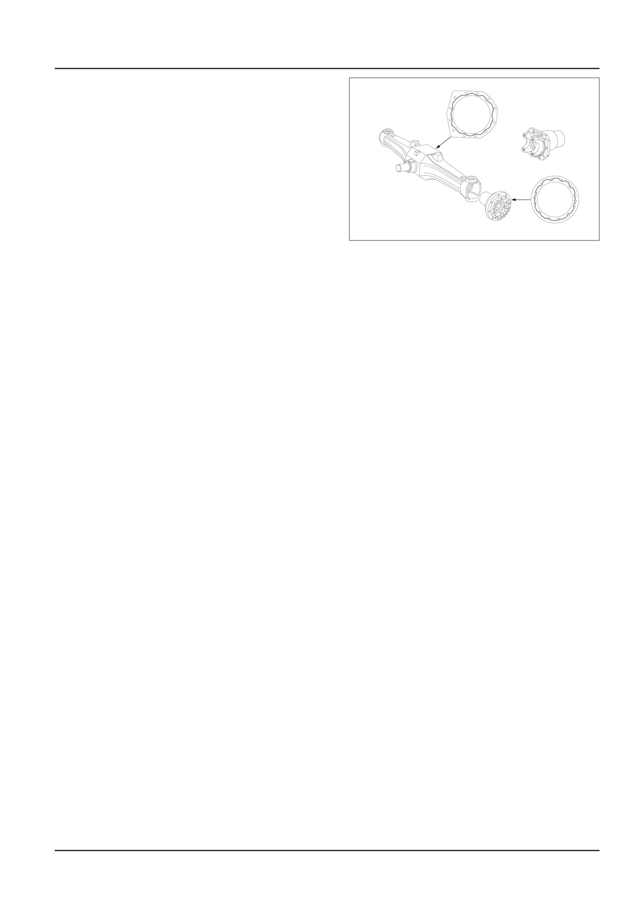
10. Attach the bevel drive/differential to the axle casing af-
ter having carefully cleaned and degreased the mat-
ing surfaces and applied a bead of gasket eliminator
LOCTITE® 518, approx. 2 mm (0.08 in) wide along the
line shown in the figure.
25.1 [25.100] / 28
Front axle system - Powered front axle
11. Gasket eliminator LOCTITE® 518 application diagram
for assembly of bevel drive unit and epicyclic final
drive unit.
GNIL14TR04394AB
7
25.1 [25.100] / 29
Front axle system - Powered front axle
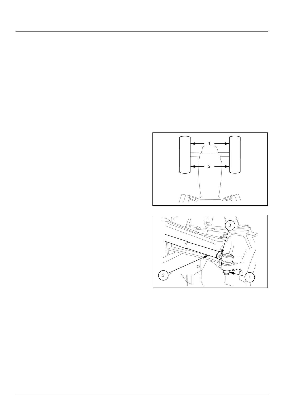
Four-Wheel Drive (4WD) axle - Toe in adjust
When travelling forward in a straight path, the wheels
of four-wheel drive tractors must be parallel to the lon-
gitudinal axis of the tractor, alternatively a slight toe-in
of the front wheels is permissible up to a maximum of
6 mm (0.24 in) as measured at the edges of the wheel
rims.
To check the exact value of the toe-in setting of four-
wheel drive tractors, proceed as follows.
1.
Inflate the front tires to the prescribed pressure.
2.
Position the steering at the straight ahead position
(along the longitudinal axis of the tractor).
3.
Check that the wheels are parallel to the longitudinal
axis of the tractor.
4.
Make a chalk mark on the front inside edges of both
wheel rims, at the height of the wheel hub centers.
Measure the distance (1) between the chalk marks.
5.
Move the tractor forward to turn both front wheels
through 180 °The chalk marks will now be measure
between the rear inside edges of the wheel rims at the
height of the wheel hub centers. Now measure the
distance (2) checking that this new measurement is
equal to or greater than the distance (1) by a maximum
or 6 mm (0.24 in).
The rotation of the wheels through 180 ° is necessary to
eliminate the effect of wear, misalignment or distortion
of the wheel rims on the measurements obtained.
GNIL14TR04416AB
1
6.
If it is necessary to correct the wheel alignment, re-
move nut (1) and pull the tie rod end out of its housing.
Loosen the locknut (2) and screw the tie rod end (3) in
or out to increase or decrease the distance (2).
Reposition the tie rod end in its housing and re-check
alignment.
After having adjusted the toe in to within the prescribed
limits, tighten locknut (2) to a torque of 180 N·m (133 lb
ft) and nut (1) to 100 N·m (74 lb ft).
NOTE: The self-locking nut (1), must be replaced each time
it is removed or partially unscrewed.
GNIL14TR04400AB
2
25.1 [25.100] / 30
Index
Front axle system - 25
Powered front axle - 100
Four-Wheel Drive (4WD) axle - Adjust
27
Four-Wheel Drive (4WD) axle - Assemble
26
Four-Wheel Drive (4WD) axle - Disassemble
19
Four-Wheel Drive (4WD) axle - General specification
3
Four-Wheel Drive (4WD) axle - Inspect
25
Four-Wheel Drive (4WD) axle - Install
18
Four-Wheel Drive (4WD) axle - Overview
8
Four-Wheel Drive (4WD) axle - Remove
12
Four-Wheel Drive (4WD) axle - Remove
15
Four-Wheel Drive (4WD) axle - Sectional view
9
Four-Wheel Drive (4WD) axle - Special tools
6
Four-Wheel Drive (4WD) axle - Toe in adjust
30
Four-Wheel Drive (4WD) axle - Torque
5
25.1 [25.100] / 31
Front axle system - 25
Front bevel gear set and differential - 102
Workmaster™ 50
Workmaster™ 60
Workmaster™ 70
25.2 [25.102] / 1
Contents
Front axle system - 25
Front bevel gear set and differential - 102
SERVICE
Differential
Adjust - 4WD Front axle
3
25.2 [25.102] / 2
Front axle system - Front bevel gear set and differential
Differential - Adjust - 4WD Front axle
Prior operation:
Four-Wheel Drive (4WD) axle - Disassemble (25.100).
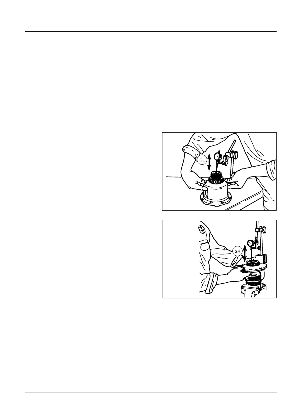
End play adjustment
In case of differential assembly overhaul it is necessary
to adjust the backlash between the teeth of the planet
pinions and side gears.
Proceed as follows:
1. Thoroughly clean the components of the differential to
remove any traces of oil which would otherwise prevent
accurate backlash measurement.
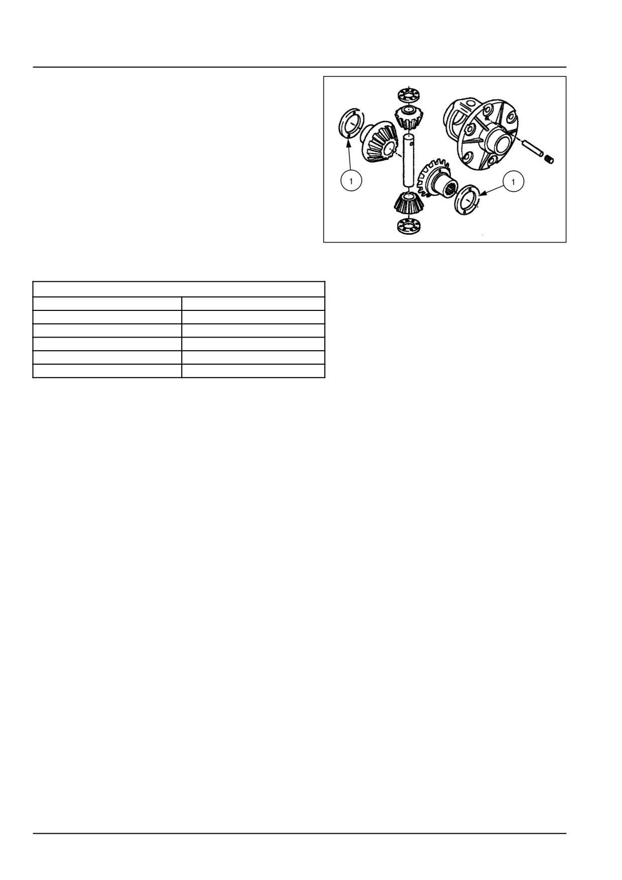
2. Install the two side gears without thrust washers.
3. Install the planet pinions complete with thrust washers
and pins and screw the pin retaining bolts in by a few
turns to hold the pins in place.
4. Position a dial gauge on the differential housing.
5. Move the left-hand side gear to bring it into full contact
with the planet pinion and then push it up against the
differential housing, reading the end play (GL) on the
dial gauge.
20097712
1
6. Repeat the above operations to measure the end play
on the right-hand side gear (GR).
The end play should be 0.25 mm (0.010 in). Therefore
the shims to be inserted in the differential housing are
given by:
Shim (left) = GL - 0.25 mm (0.010 in) for the left-hand
side gear.
Shim (right) = GR - 0.25 mm (0.010 in) for the right-
hand side gear.
20097713
2
25.2 [25.102] / 3
Front axle system - Front bevel gear set and differential
7. Install shims, (1), as near as possible to the calculated
value. Use a dial gauge and following the procedure
described above, check that the end float of the left
and right-hand side gears is approximately 0.25 mm
(0.010 in).
20097714
3
Differential side gear shim sizes
Available shim sizes mm (inches)
1.0 mm (0.039 in)
1.6 mm (0.063 in)
1.1 mm (0.043 in)
1.7 mm (0.067 in)
1.2 mm (0.047 in)
1.8 mm (0.071 in)
1.3 mm (0.051 in)
1.9 mm (0.075 in)
1.4 mm (0.055 in)
2.0 mm (0.039 in)
1.5 mm (0.059 in)
25.2 [25.102] / 4
Index
Front axle system - 25
Front bevel gear set and differential - 102
Differential - Adjust - 4WD Front axle
3
25.2 [25.102] / 5
Front axle system - 25
Final drive hub, steering knuckles, and shafts - 108
Workmaster™ 50
Workmaster™ 60
Workmaster™ 70
25.3 [25.108] / 1
Contents
Front axle system - 25
Final drive hub, steering knuckles, and shafts - 108
SERVICE
Steering knuckle and king pin
Remove
3
Adjust (Stub Axle)
4
Wheel hub
Adjust (4WD) - Front Axle
6
25.3 [25.108] / 2