New Holland Tractor Workmaster 50 / Workmaster 60 / Workmaster 70 / Tier 4B (final). SERVICE MANUAL - page 5
Transmission - Gearbox internal components
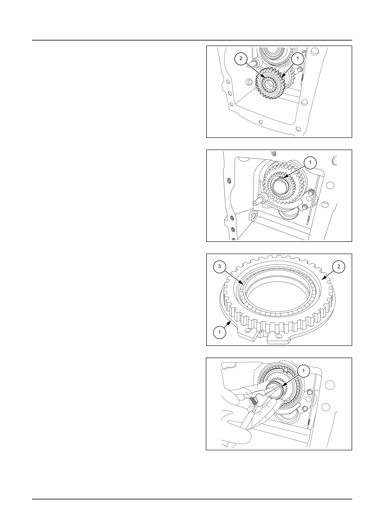
12. Remove the cluster gear shaft (1) from the ball bear-
ing.
13. Remove the ball bearing (2) from the cluster gear shaft
(1).
GNIL14TR04203AB
8
14. Remove the external circlip (1) from the groove of the
input shaft.
15. Remove the shuttle coupler gear assembly from the
input shaft.
GNIL14TR04204AB
9
16. Remove the external retaining ring (1) from the groove
of coupler shuttle gear (2).
17. Remove the ball bearing (3) inside the coupler shuttle
gear (2).
GNIL14TR04205AB
10
18. Remove the snap ring (1) from the groove of the input
shaft.
GNIL14TR04206AB
11
21.4 [21.145] / 5
Transmission - Gearbox internal components
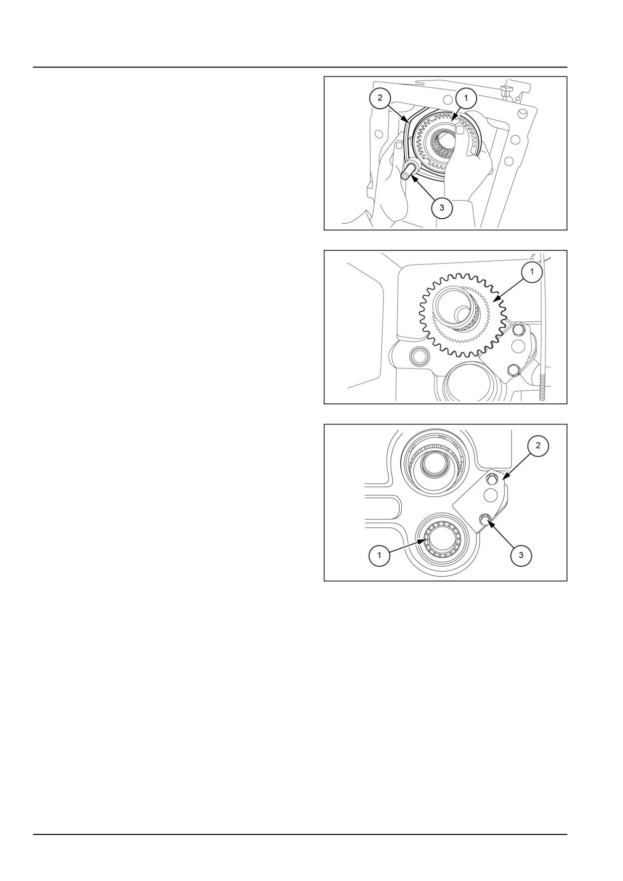
19. Remove the synchronizer kit (1) shift fork (2) and rail
(3).
GNIL14TR04207AB
12
20. Remove the reverse gear (1).
GNIL14TR04208AB
13
21. Remove the ball bearing (1) from the rear of the clutch
housing.
22. Remove the oil trench plate (2) from the housing sur-
face by loosening the M8 bolts and washers (3).
GNIL14TR04209AB
14
21.4 [21.145] / 6
Transmission - Gearbox internal components
Gearbox internal components - Inspect
1. Wash all parts in a suitable cleaning solution and allow
to air dry.
2. Inspect the bearings for excess wear, score marks ,
discoloration from overheating or other damage. Ro-
tate the bearings by hand and check for any roughness.
Replace as necessary.
3. Inspect the synchronizer gears and cluster gear shaft
for excess wear, chipped gear teeth, cracks or any
other damage. Replace as necessary.
4. Inspect the shift fork for wear or damage. Replace as
necessary.
5. Inspect the detent grooves in the shift rail for excess
wear. Replace as necessary.
6. Check the detent spring for wear or weak spring ten-
sion. Replace as necessary.
21.4 [21.145] / 7
Transmission - Gearbox internal components
Gearbox internal components - Install
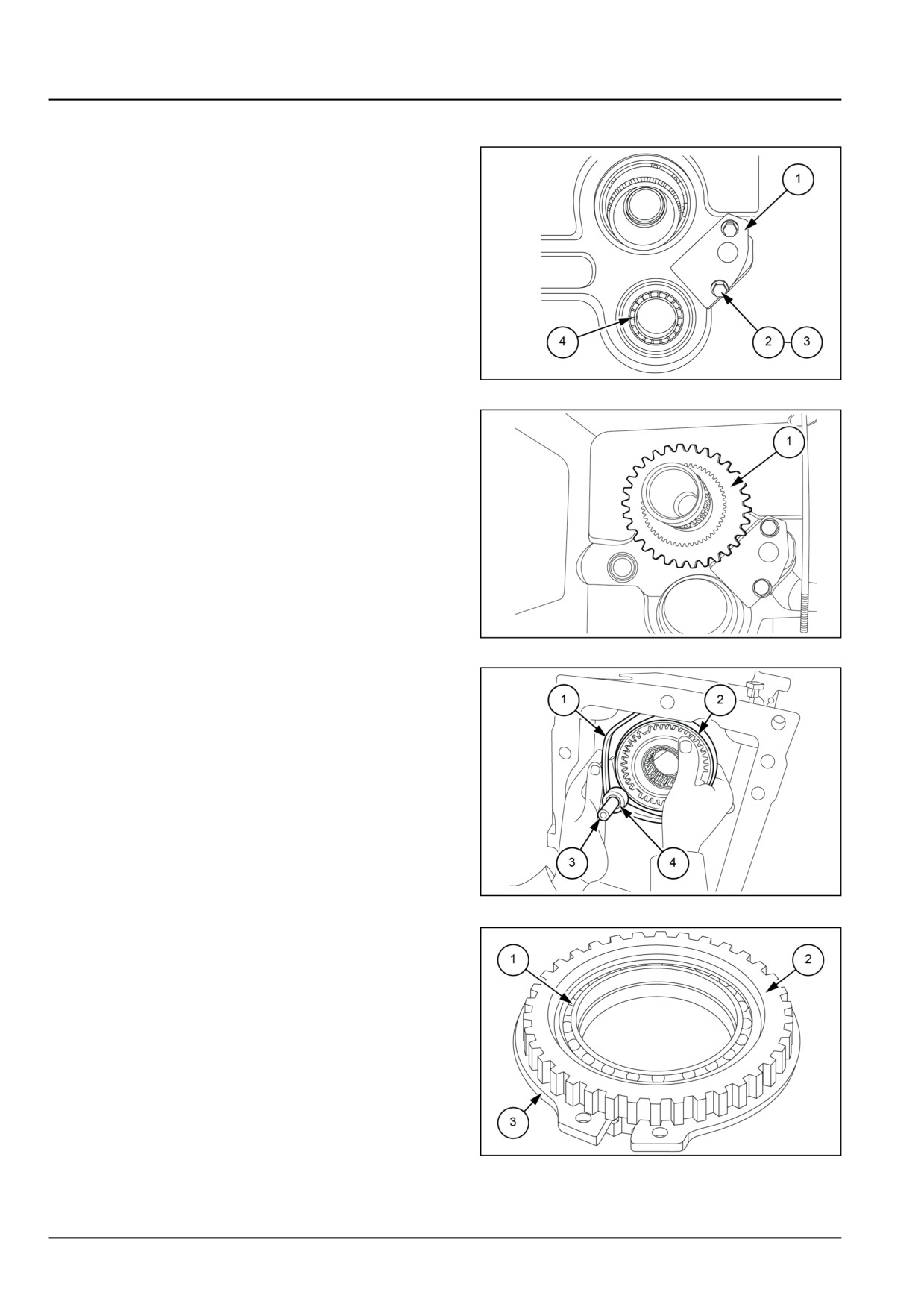
1. Place the oil trench plate (1) on the housing surface
and tighten the bolts (2) with washer (3) to 25.5 N·m
(18.8 lb ft).
2. Install the ball bearing (4) from the rear of the clutch
housing.
GNIL14TR04210AB
1
3. Install the reverse gear (1) over the input shaft spacer.
GNIL14TR04211AB
2
4. Install the shift fork (1) onto the synchronizer (2).
5. Insert the shift rail (3) through the shift fork (1).
NOTE: Secure the spring and detent ball against the
groove on the shift rail by installing the shuttle detent bolt
on the left-hand side of the clutch housing.
6. Install roll pin (4) after aligning the hole of the shift fork
(1) and shift rail (3).
7. Install the synchronizer kit (1) onto the spline of the
input shaft.
8. Secure the synchronizer on the input shaft with the ex-
ternal retaining ring (2).
GNIL14TR04212AB
3
9. Press the ball bearing (1) inside the coupler shuttle gear
(2).
10. Attach the external snap ring (3) onto the groove of
coupler shuttle gear (2).
GNIL14TR04214AB
4
21.4 [21.145] / 8
Transmission - Gearbox internal components
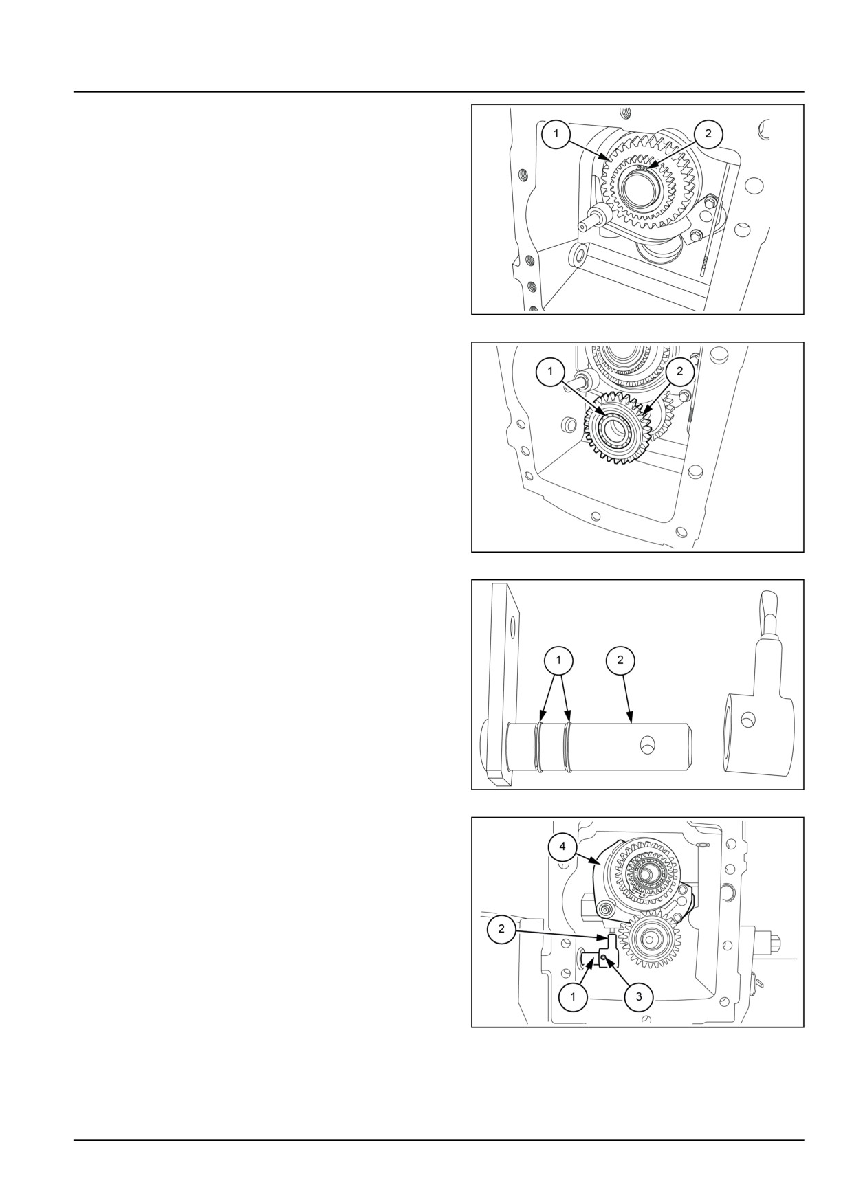
11. Install the shuttle coupler gear assembly (1) over the
input shaft.
12. Secure the shuttle coupler gear on the input shaft with
the external snap ring (2).
GNIL14TR04215AB
5
13. Press the ball bearing (1) into the cluster gear shaft
(2).
14. Install the cluster gear shaft (2) into the ball bearing
installed from step 2.
GNIL14TR04216AB
6
15. Apply petroleum jelly to the O-rings (1).
16. Insert the O-rings in the grooves on the shaft link rod
(2).
GNIL14TR04217AB
7
17. Insert the shaft link rod (1) through the hole in the
clutch housing.
18. Insert the lever link rod (2) in the shift fork (4).
19. Slide the shaft link rod (1) into the lever link rod (2).
20. Align the holes in the shaft link rod (1) with the holes
in the lever link rod (2). Secure using the roll pin (3).
GNIL14TR04218AB
8
21.4 [21.145] / 9
Transmission - Gearbox internal components
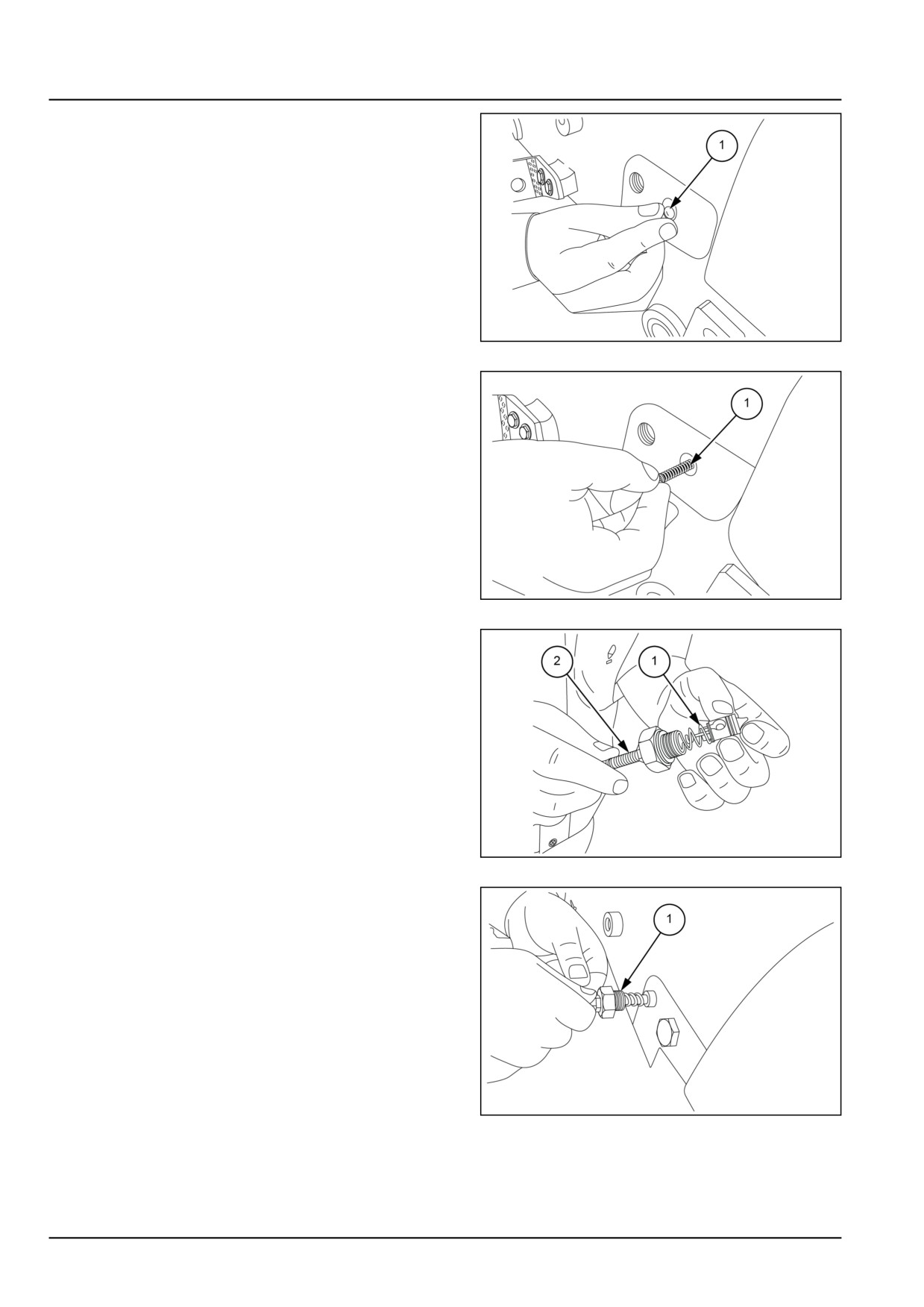
21. Insert the detent ball (1) in front of the spring.
GNIL14TR04219AB
9
22. Insert the spring (1) into the clutch housing.
23. Install the shuttle detent bolt to the left-hand side of
the clutch housing.
GNIL14TR04220AB
10
24. Insert the pin and spring (1) to shuttle cable (2).
GNIL14TR04221AB
11
25. Insert the shuttle cable (1) through the hole on the
left-hand side of the clutch housing.
GNIL14TR04222AB
12
21.4 [21.145] / 10
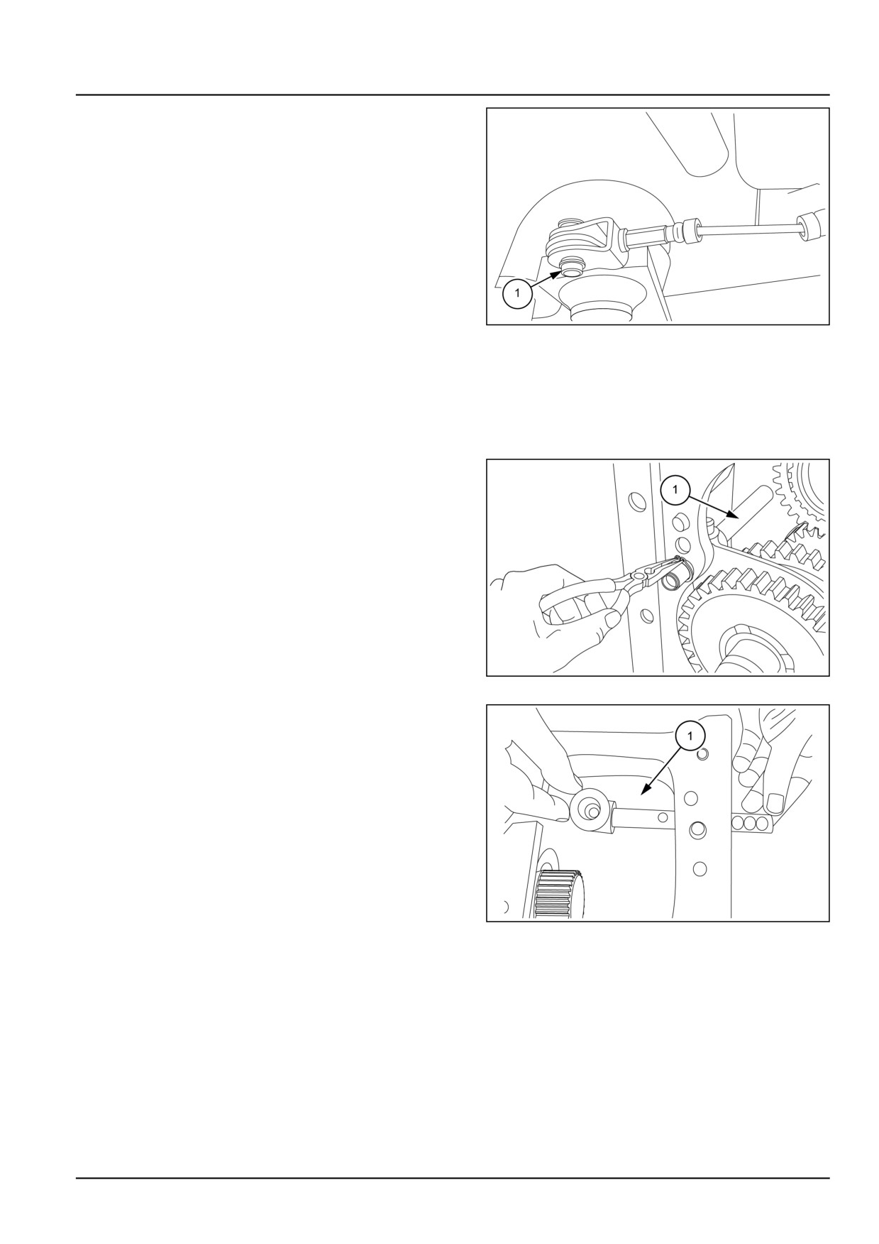
Transmission - Gearbox internal components
26. Attach the cable on the linkage and secure with the
snap ring (1).
27. Attach the linkage to the shaft link rod. Secure using
the pin and cotter pin.
GNIL14TR04223AB
13
Synchro shuttle rails and fork
28. To install the shift rail and shift forks follow the proce-
dure as mentioned below.
29. Insert shuttler rail.
30. Insert the bottom shift rail (1) and 1st/2nd gearshift
fork. Insert the snap ring (2) on the bottom shift rail
and ensure it sits on the seat in housing.
GNIL14TR04227AB
14
31. The Hi/Low shift rail (1) shift fork and shift gate should
be installed after the pinion and crown settings.
NOTE: Keep grooves of rails upward to make easy fitment
of balls and springs.
GNIL14TR04228AB
15
21.4 [21.145] / 11
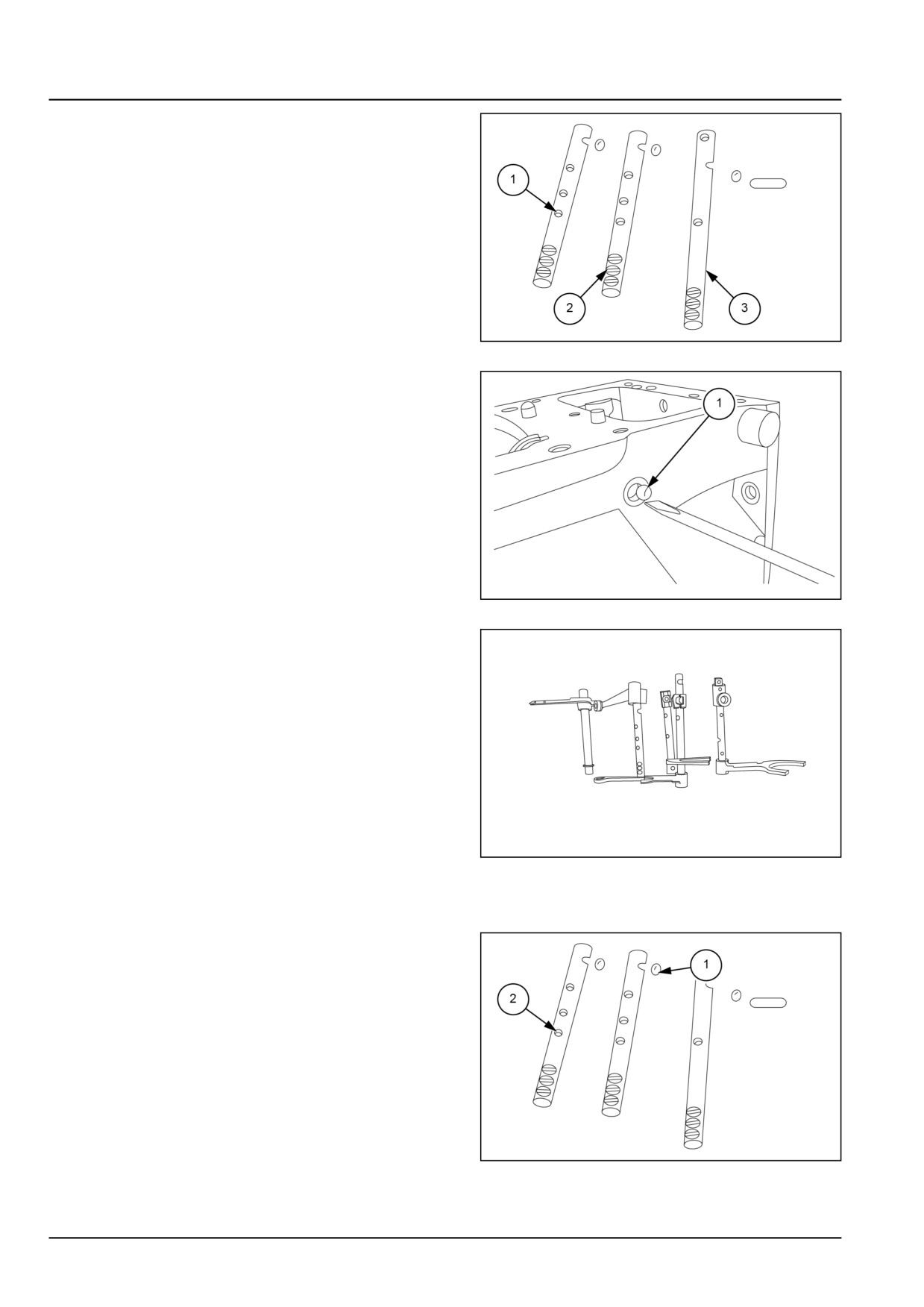
Transmission - Gearbox internal components
32. Transmission shift rails can be identified by referring to
figure 3. To fit rails 1st/2nd (1) and 3rd/4th (2) rails are
similar. After fitting range shaft and drive shaft fit fork
for 3rd/4th and insert reverse rail (3), passing through
fork of 3rd/4th gear.
GNIL14TR04229AB
16
33. After fitting reverse rail insert ball (1), applying some
grease in the housing.
GNIL14TR04230AB
17
34. Insert the rail (1) of 3rd/4th with gate (2) passing
through fork (3) of 3rd/4th gear as shown in figure 18.
GNIL14TR04231AA
18
35. Insert gate of 1st/2nd rail shaft on the notch of 1st/ 2nd
gear fork.
36. Insert the ball (1) applying some grease in housing
after removing bolt as shown in figure 17.
GNIL14TR04232AB
19
21.4 [21.145] / 12
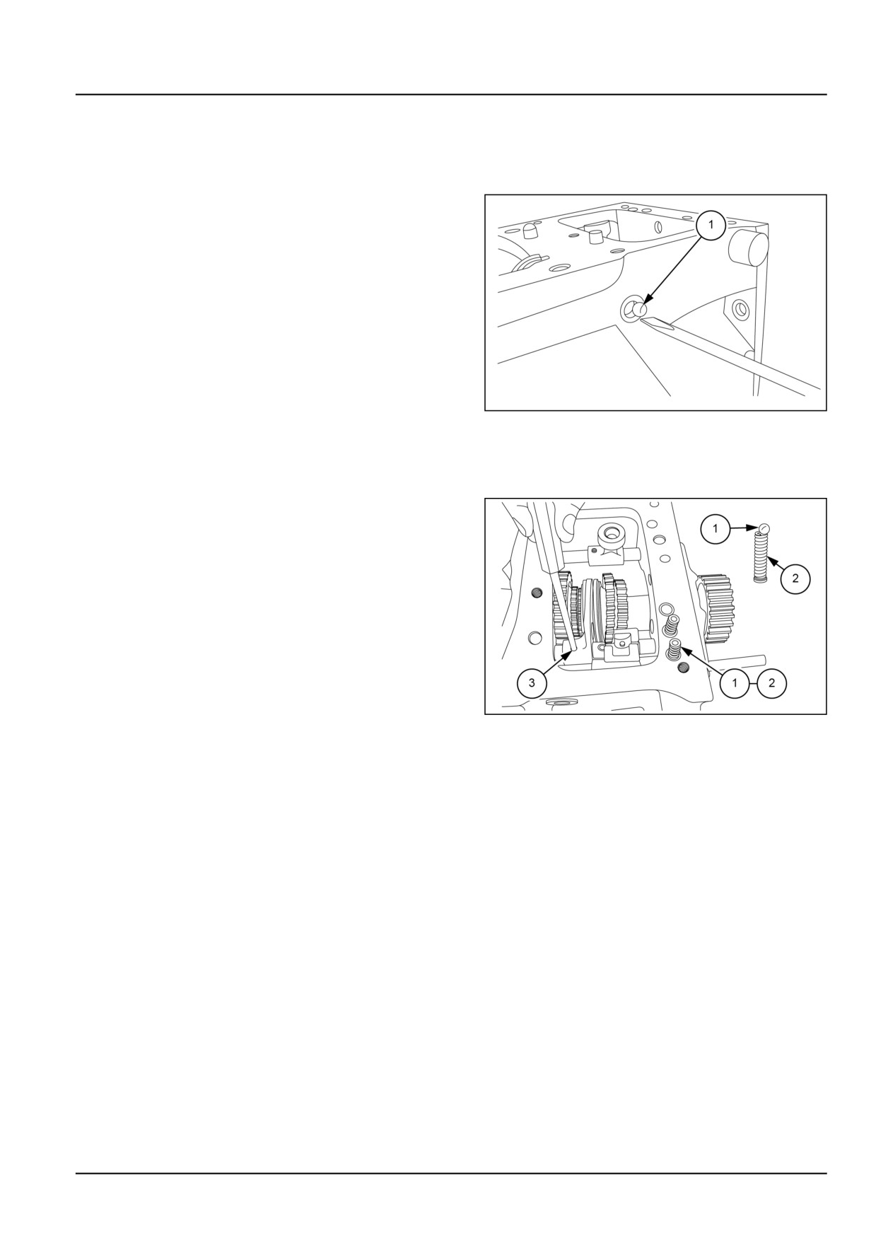
Transmission - Gearbox internal components
37. Insert the 1st/2nd rail (2) passing thru gate as shown
in figure 18.
NOTE: Keep grooves of rails upward to make easy fitment
of balls and springs.
38. Insert the ball and pin (1) after removing neutral safety
switch for Hi/Low rail then fit neutral safety switch and
tighten it.
GNIL14TR04230AB
20
39. After fitting reverse rail insert ball (1) applying some
grease in the housing as such it sits in groove given
on reverse rail.
40. Insert the balls (1) and springs (2) of the rails. Insert
plug above the spring of Hi/Low rail. Fit roll pins (3) in
all rails and gates.
GNIL14TR04234AB
21
21.4 [21.145] / 13
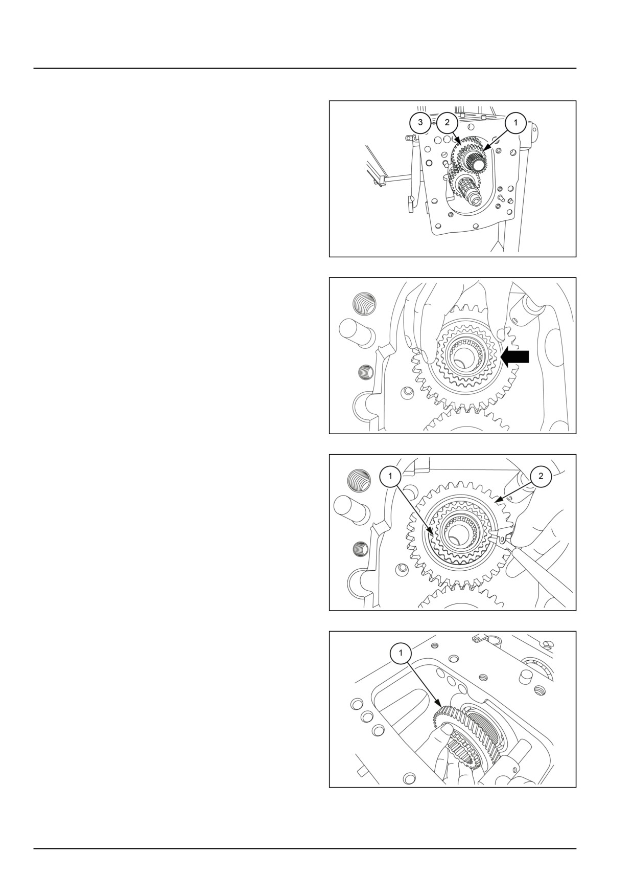
Transmission - Gearbox internal components
Drive shaft - Remove
1. Remove the drive shaft (1) 3rd gear drive gear (2) and
3rd/4th gear coupler (3) as a assembly from the trans-
mission housing.
NOTE: 1st and 2nd gear are a integral part of the drive
shaft.
GNIL14TR04174AB
1
2. Remove shims.
GNIL14TR04175AB
2
3. Remove the snap ring (1) securing the 4th gear drive
gear (2) on the range shaft.
GNIL14TR04176AB
3
4. Remove the 4th gear drive gear (1) from the range
shaft.
GNIL14TR04177AB
4
21.4 [21.145] / 14
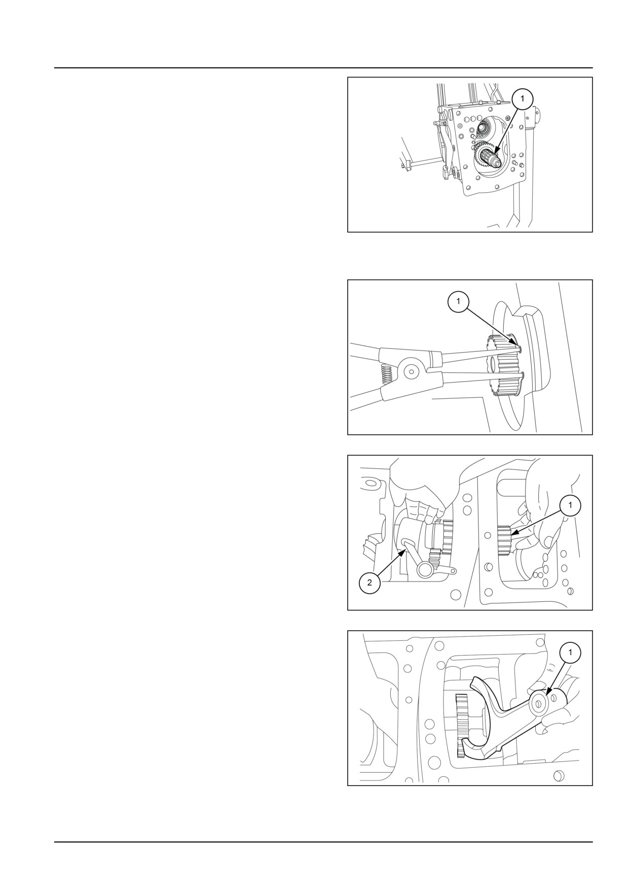
Transmission - Gearbox internal components
5. Remove the driven shaft (1) from the housing.
NOTE: 3rd and 4th gears are a integral part of the driven
shaft.
6. Clean and inspect the gears and hub for excess wear,
chipped gear teeth, cracks or any other damage. Re-
place as necessary.
7. Inspect the shift fork for wear or damage. Replace as
necessary.
8. Inspect the shift rail for wear or damage. Replace as
necessary.
GNIL14TR04178A
5
Range shaft removal
9. Remove the circlip lock (1) of the range shaft.
GNIL14TR04065AB
6
10. Remove the range shaft (1) from the housing. Re-
move the oil feeder cup (2) from the shaft as shown.
GNIL14TR04066AB
7
11. After removing the high low rail take out high low fork
(1).
NOTE: It is required to take out the spacer (2), spring and
ball of high low rail shaft from the housing.
GNIL14TR04067AB
8
21.4 [21.145] / 15
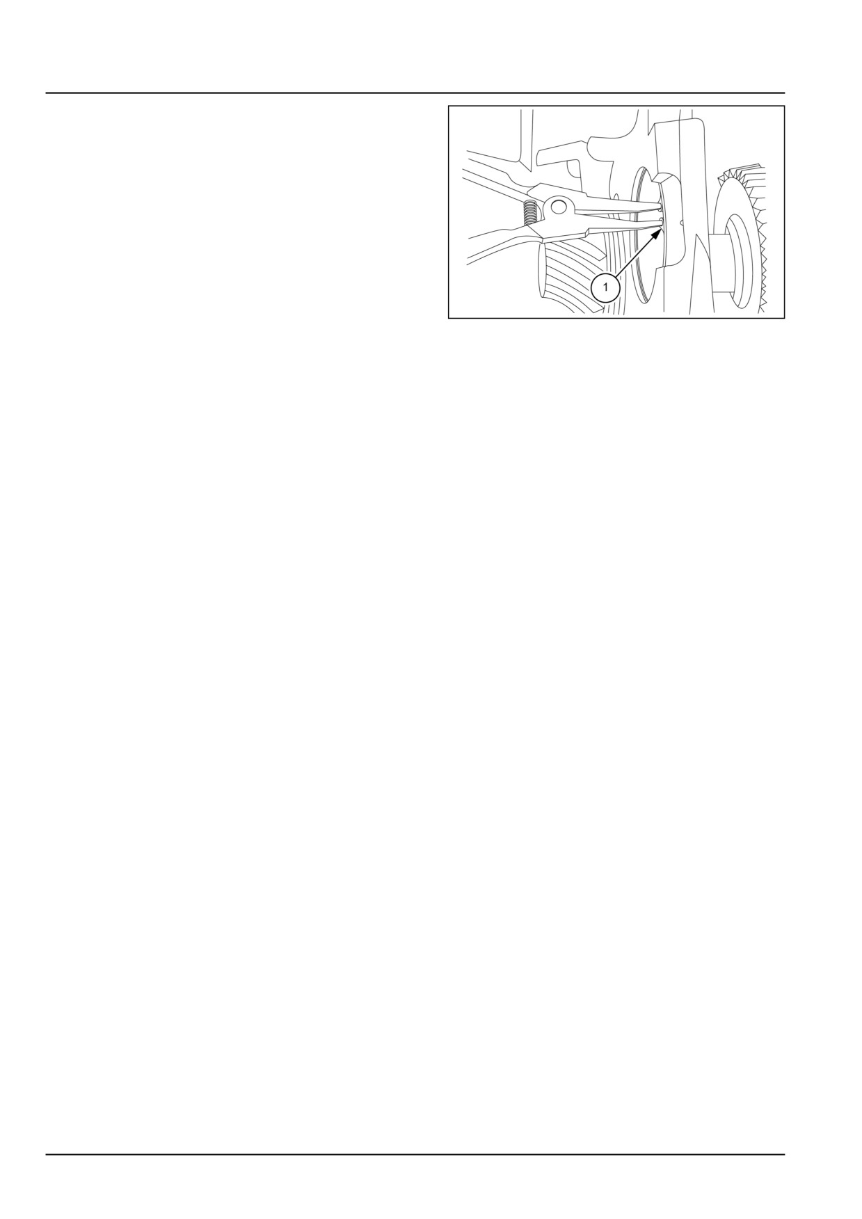
Transmission - Gearbox internal components
12. Remove the range shaft. Remove the snap ring (1) of
range shaft bearing. Remove the range shaft bearing.
GNIL14TR04068AB
9
21.4 [21.145] / 16
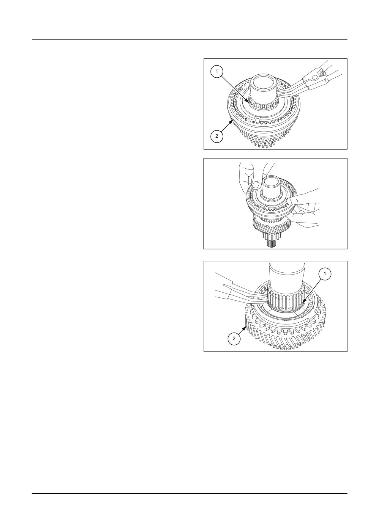
Transmission - Gearbox internal components
Drive shaft - Disassemble
1. Remove the snap ring (1) from the drive shaft to remove
the hub along with coupler.
GNIL14TR04179AB
1
GNIL14TR04180AA
2
2. Remove the snap ring (1) from the drive shaft. Remove
the 3rd drive gear (2).
NOTE: 1st and 2nd gear are a integral part of the drive
shaft.
GNIL14TR04181AB
3
21.4 [21.145] / 17
Transmission - Gearbox internal components
Drive shaft - Inspect
1. Wash all parts in a suitable cleaning solution and allow
to air-dry.
2. Inspect all gears for excess wear chipped gear teeth
cracks or any other damage. Replace as necessary.
3. Inspect the gear coupler and synchromesh drive shaft
for any cracks or damage. Replace as necessary.
21.4 [21.145] / 18
Transmission - Gearbox internal components
Driven shaft - Remove
1. Remove the bottom shift rail (1).
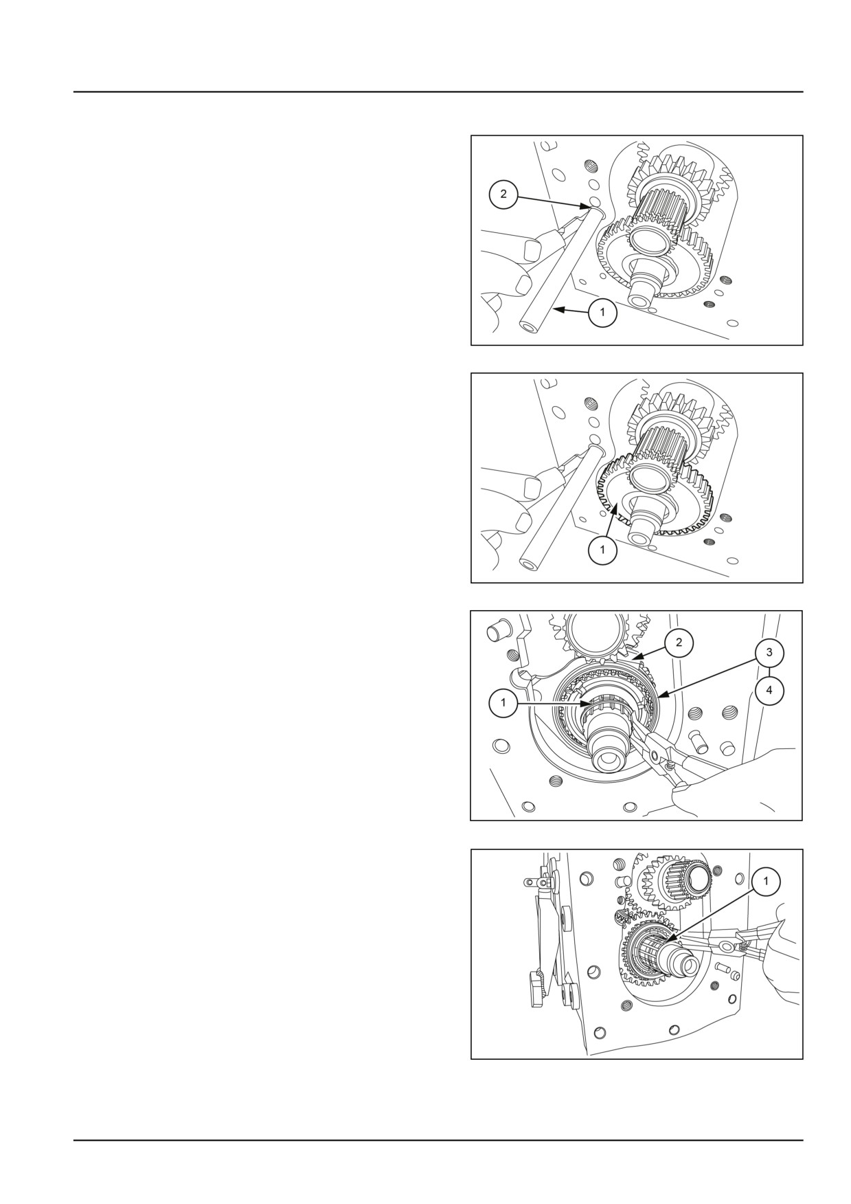
NOTE: The bottom shift rail has a M12 plug (2) that must
be removed from the front of the housing.
GNIL14TR04169AB
1
2. Remove the 1st gear (1) off the synchromesh driven
shaft.
GNIL14TR04170AB
2
3. Remove the snap ring (1) from the driven shaft. Take
out the 1st/2nd gear shift fork (2), the 1st/2nd gear cou-
pler (3), and the hub (4) of the driven shaft.
NOTE: Keep the face of the hub with the cut towards the
pinion side.
GNIL14TR00867AA
3
4. Remove the snap ring (1) that secures the 2nd gear.
GNIL14TR04172AB
4
21.4 [21.145] / 19
Transmission - Gearbox internal components
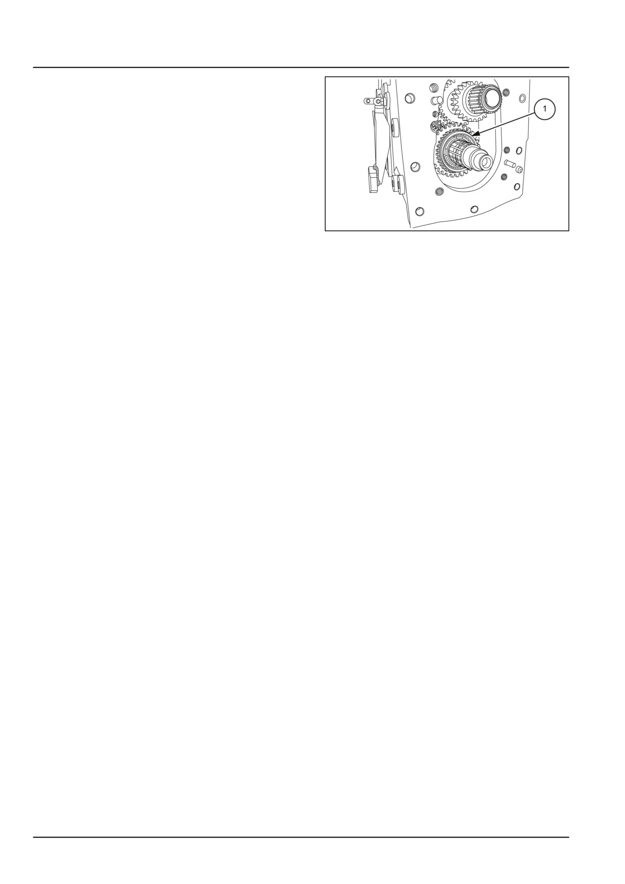
5. Remove the 2nd gear (1) from driven shaft.
GNIL14TR04173AB
5
21.4 [21.145] / 20
Transmission - Gearbox internal components
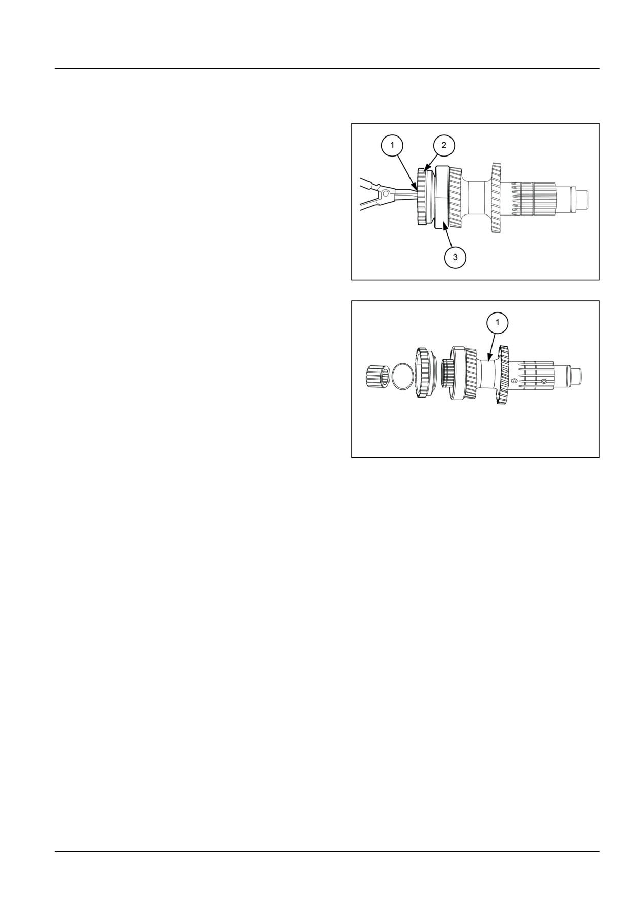
Driven shaft - Disassemble
Dismantling on bench
1. Remove the snap ring (1) to remove the high gear (2)
and bearing (3) from the synchromesh driven shaft.
GNIL14TR04182AB
1
NOTE: 3rd and 4th gear are a integral part of the driven
shaft (1).
GNIL14TR04183AB
2
21.4 [21.145] / 21
Transmission - Gearbox internal components
Driven shaft - Inspect
1. Wash all parts in a suitable cleaning solution and allow
to air dry.
2. Inspect the bearing for excess wear, score marks, dis-
coloration from overheating or other damage. Rotate
the bearing by hand and check for any roughness while
turning. Replace as necessary.
3. Inspect all the gears and driven shaft for excess wear
chipped gear teeth cracks or any other damage. Re-
place as necessary.
4. Inspect synchronizer ring spring loaded poppet valve
dog for wear.
21.4 [21.145] / 22
Transmission - Gearbox internal components
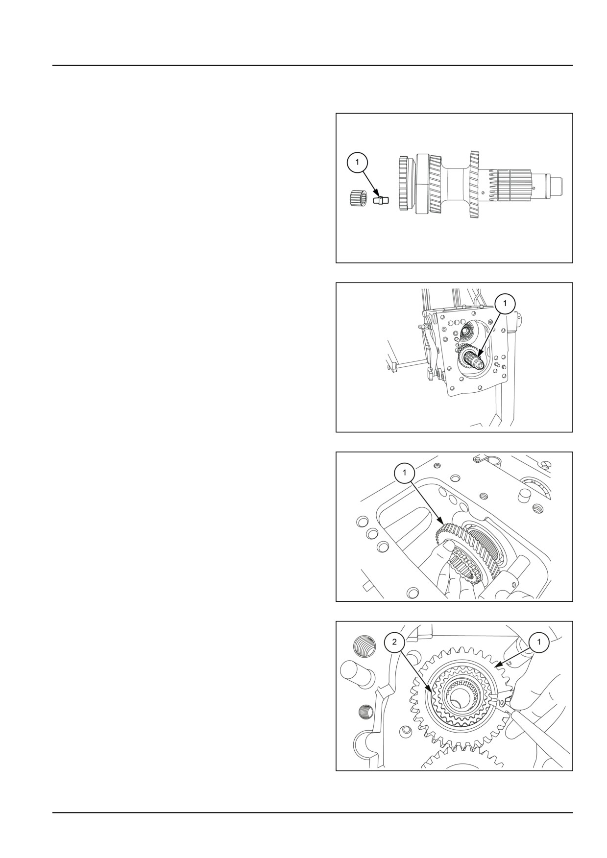
Driven shaft - Install Transmission drive and driven shafts
NOTE: Before assembly carefully check gears needle bearing snap rings etc. and replace if found faulty.
1. Fit the oil connector (1) between driven shaft and pin-
ion keeping larger diameter towards driven shaft before
fitting driven shaft on pinion.
GNIL14TR04184AB
1
2. Install the driven shaft (1) into the housing.
NOTE: 3rd and 4th gears are a integral part of the driven
shaft.
GNIL14TR04185AB
2
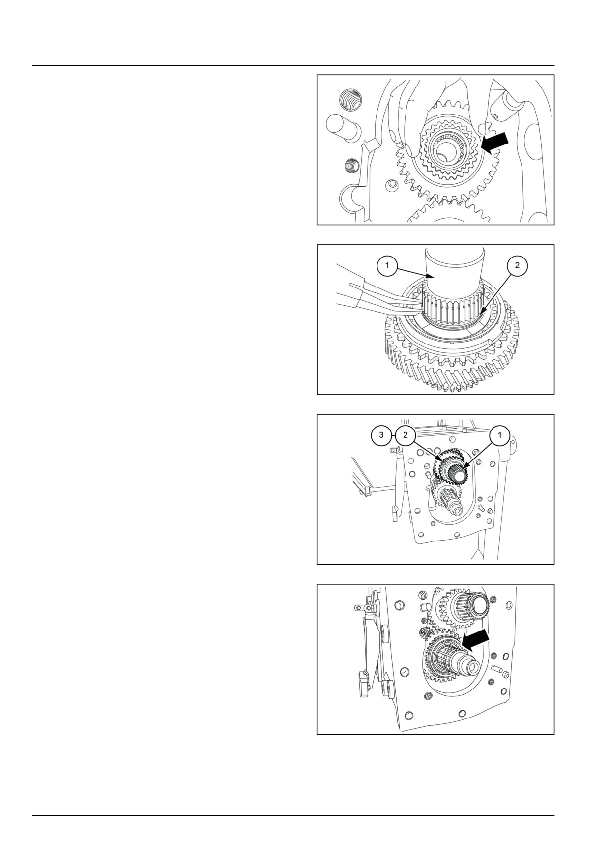
3. Install the 4th gear drive gear (1) onto the range shaft.
GNIL14TR04186AB
3
4. Secure the 4th gear drive gear (1) with the snap ring
(2).
GNIL14TR04187AB
4
21.4 [21.145] / 23
Transmission - Gearbox internal components
5. Install shims and synchronizer ring on the 4th gear.
GNIL14TR04188AB
5
6. Instal 3rd gear with synchronizer on drive shaft (1) and
retain with snap ring (2).
GNIL14TR04189AB
6
7. Install the synchromesh drive shaft (1) in assembled
form which includes the drive shaft 3rd gear drive gear
(2) and 3rd / 4th gear coupler (3).
NOTE: 1st and 2nd gear are a integral part of the drive
shaft.
GNIL14TR04190A
7
8. Install synchronizer ring.
GNIL14TR04191AB
8
21.4 [21.145] / 24
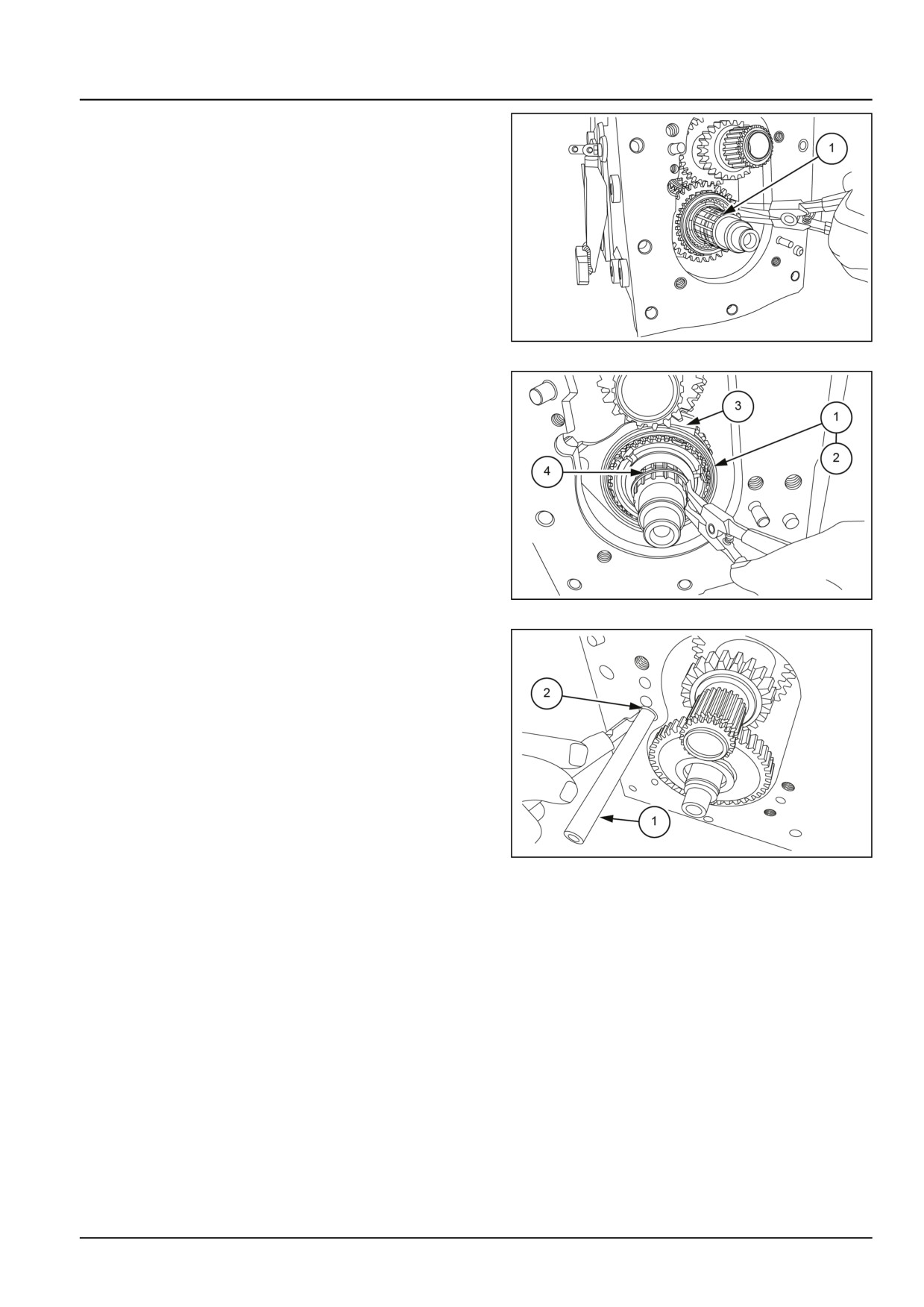
Transmission - Gearbox internal components
9. Install 2nd gear onto the synchromesh driven shaft and
secure 2nd gear with a snap ring (1).
GNIL14TR04192AB
9
10. Install the hub (1) 1st/2nd gear coupler (2) onto the
driven shaft and insert the shift fork (3) onto the cou-
pler. Secure the hub with the snap ring (4).
NOTE: Keep the face of the hub with the cut towards the
pinion side.
GNIL14TR04193AB
10
11. Secure the shift fork in place by inserting the bottom
shift rail (1).
NOTE: Insert the M12 plug (2) for the shift rail into the hous-
ing.
GNIL14TR04194AB
11
21.4 [21.145] / 25
Index
Transmission - 21
Gearbox internal components - 145
Drive shaft - Disassemble
17
Drive shaft - Inspect
18
Drive shaft - Remove
14
Driven shaft - Disassemble
21
Driven shaft - Inspect
22
Driven shaft - Install Transmission drive and driven shafts
23
Driven shaft - Remove
19
Gearbox internal components - Inspect
7
Gearbox internal components - Install
8
Gearbox internal components - Remove
3
21.4 [21.145] / 26
Transmission - 21
Dropbox - 200
Workmaster™ 50
Workmaster™ 60
Workmaster™ 70
21.5 [21.200] / 1
Contents
Transmission - 21
Dropbox - 200
SERVICE
Dropbox
Remove
3
Disassemble
4
Assemble
5
Install
6
21.5 [21.200] / 2
Transmission - Dropbox
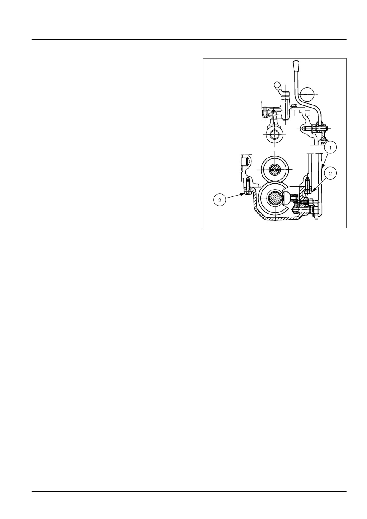
Dropbox - Remove
1. After removing the drive shaft, drain the oil from the
tractor transmission. See Drive shaft
- Remove
(23.314) for the drive shaft removal.
2. Detach the hand lever vertical rod (1) from the drop box
control lever.
3. Remove the mounting bolts (2) and remove the drop
box assembly.
NOTE: Drain the oil from the drop box by removing the
drain plug on the drop box.
20097721
1
21.5 [21.200] / 3
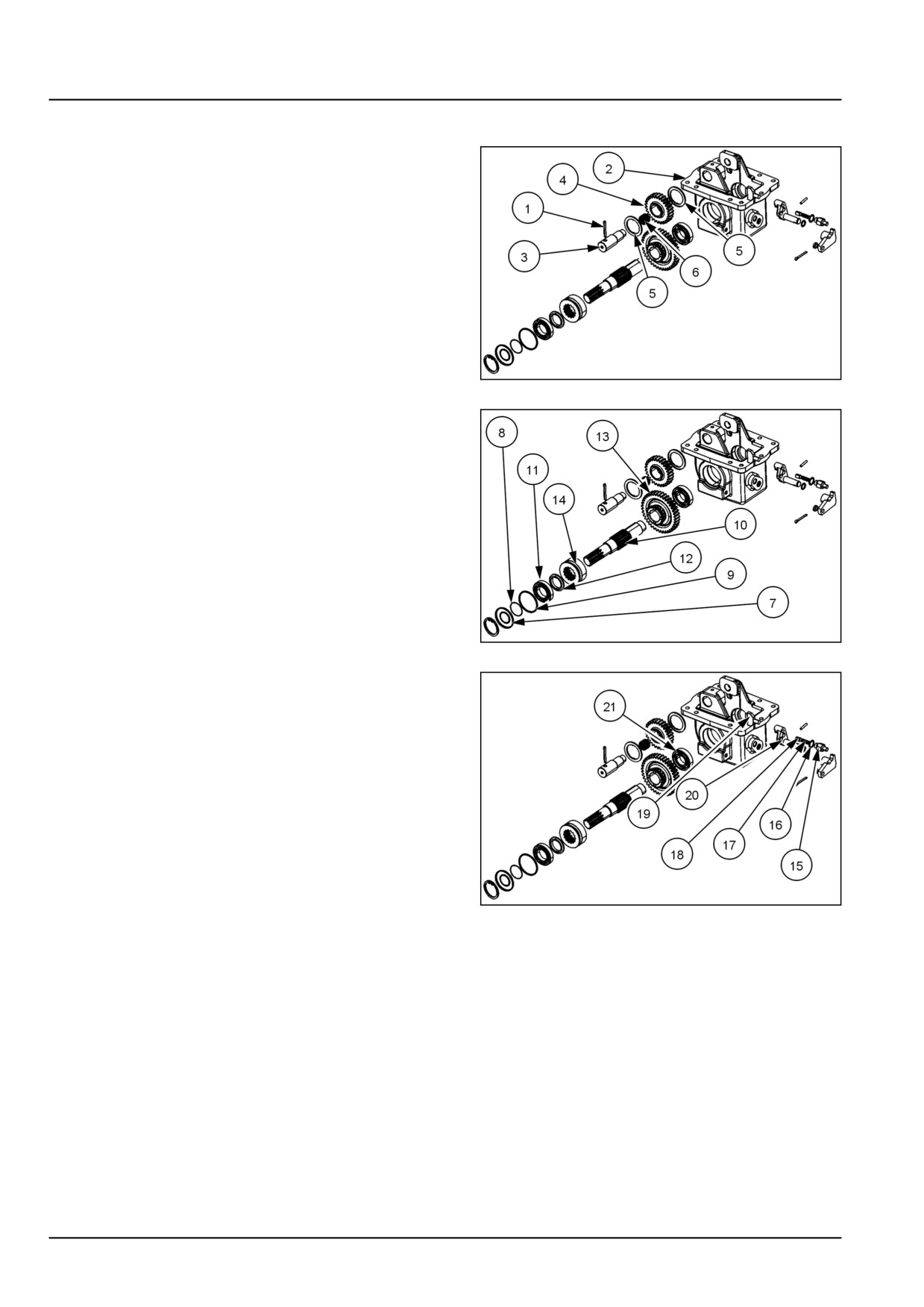
Transmission - Dropbox
Dropbox - Disassemble
1. Use a punch to remove the roll pin (1) from the drop
box (2) and idler gear shaft (3).
2. Push the idler gear shaft (3), forward out of the drop
box (2) and remove the idler gear (4), spacers (5), and
needle bearing (6) from the drop box.
3. Check the idler gear shaft, idler gear, spacers, and nee-
dle bearing for any wear or damage. Replace as nec-
essary.
200900126
1
4. Remove the following :-
• Dust seal disc (7).
• Shaft seal (8).
• Retaining ring (9).
• Output shaft (10), with bearing (11), and dust ex-
cluder (12).
NOTE: Drill a 1/8 inch hole on each side of the dust seal
(7) and shaft seal (8) and insert sheet metal screws into the
holes to pull the parts from the case bore.
5. Remove the output shaft gear (13), and splined coupler
(14), from the case.
200900126
2
6. To remove shift lever :-
• Unscrew the plug (15) with sealing washer (16).
• Remove detent plunger spring (17).
• Remove detent plunger (18).
• Remove pad (19).
• Remove Inner change lever (20) from case.
7. To remove rear bearing (21) use a slide hammer puller.
200900126
3
21.5 [21.200] / 4
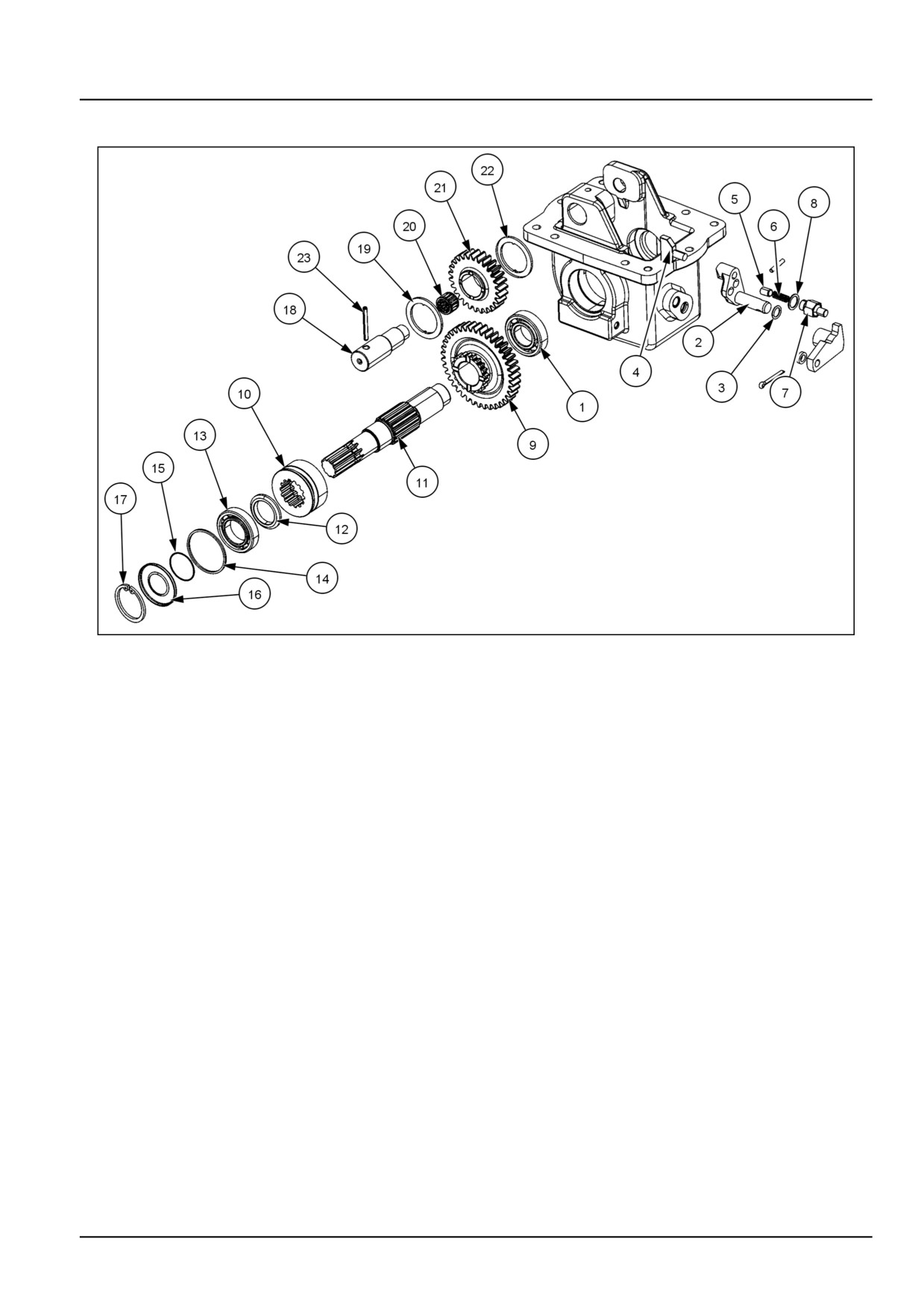
Transmission - Dropbox
Dropbox - Assemble
200900125
1
1. Install rear bearing (1) into the drop box.
2. Install inner change lever (2) with O-ring (3) into the
drop box.
3. Install pad (4) onto the changing lever.
4. Install detent plunger (5), plunger spring (6), plug (7)
with sealing washer (8).
5. Place output shaft gear (9) and splined coupler (10) into
the drop box.
6. Slide output shaft (11) through the coupler, gear and
into the rear bearing. Seat shaft fully into rear bearing.
7. Install the dust excluder (12) and the front bearing (13)
onto the output shaft.
8. Install retaining ring (14) into the groove in the drop box.
9. Install shaft seal (15) and dust seal disc (16) into the
drop box.
10. Install retaining ring (17) onto the output shaft.
11. Slide the idler gear shaft (18) into the front of the trans-
fer box and slide the spacer (19), needle bearing (20),
idler gear (21), and spacer (22) onto the shaft.
12. Secure the idler gear shaft (18) by using a punch to
drive the roll pin (23) into the shaft and drop box.
21.5 [21.200] / 5
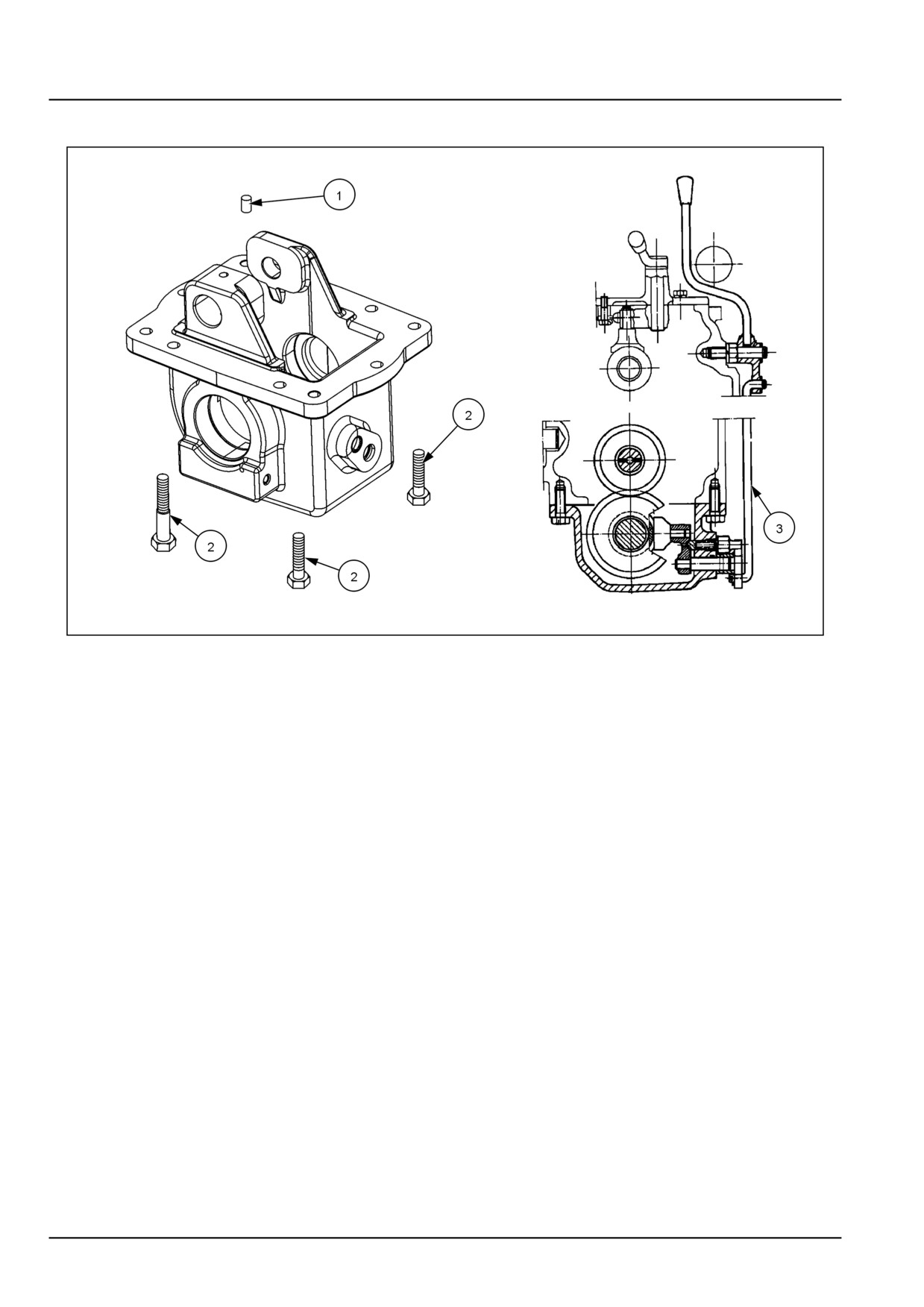
Transmission - Dropbox
Dropbox - Install
200900127
1
1. Make sure that the two locating dowel pins (1) are in-
stalled in the drop box.
2. Place a bead of gasket eliminator 518 onto the mount-
ing surface of the transfer box.
3. Install transfer box assembly onto the tractor using
eight M10 x 30 (2) mounting bolts.
4. Torque bolts to 49.0 - 62.8 N·m (36.1 - 46.3 lb ft).
5. Attach the vertical hand lever rod (3) onto the drop box
lever.
6. Refill transmission with oil.
21.5 [21.200] / 6
Index
Transmission - 21
Dropbox - 200
Dropbox - Assemble
5
Dropbox - Disassemble
4
Dropbox - Install
6
Dropbox - Remove
3
21.5 [21.200] / 7
CNH Industrial America New Holland Site 100 Brubaker Avenue New Holland, Pennsylvania United States
17557
SERVICE - Technical Publications & Tools
PRINTED IN U.S.A.
All rights reserved. No part of the text or illustrations of this publication may be reproduced.
NEW HOLLAND policy is one of continuous improvement and the right to change prices, specification or equipment
at any time without notices is reserved.
All data given in this publication is subject to production variations. Dimensions and weight are approximate only and
the illustrations do not necessarily show products in standard condition. For exact information about any particular
product, please consult your NEW HOLLAND Dealer.
EN
SERVICE MANUAL
Four-Wheel Drive (4WD) system
Workmaster™ 50
Workmaster™ 60
Workmaster™ 70
23
Contents
Four-Wheel Drive (4WD) system - 23
[23.314] Drive shaft
23.1
23
Four-Wheel Drive (4WD) system - 23
Drive shaft - 314
Workmaster™ 50
Workmaster™ 60
Workmaster™ 70
23.1 [23.314] / 1
Contents
Four-Wheel Drive (4WD) system - 23
Drive shaft - 314
SERVICE
Drive shaft
Remove
3
Install
4
23.1 [23.314] / 2
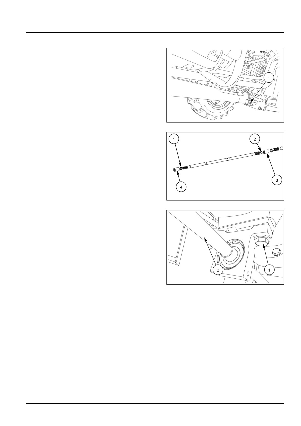
Four-Wheel Drive (4WD) system - Drive shaft
Drive shaft - Remove
1. Loosen the bolts (1) on both the ends of the Four-Wheel
Drive (4WD) shaft guard and remove the 4WD shaft
guard.
NOTE: The drive shaft guard can be separated into two
sections.
GNIL14TR00823AA
1
2. Unseat the retaining rings (1) and (2). Slide the splined
couplers (3) and (4) toward the center mounting bracket
of the 4WD shaft.
GNIL15TR01128FA
2
3. Remove the two mounting bolts (1) from center mount-
ing bracket of the 4WD shaft.
4. Remove the 4WD shaft (2).
GNIL15TR01129AA
3
5. Inspect splines of shaft, coupler and condition of bore
of center support housing for wear or damage.
23.1 [23.314] / 3
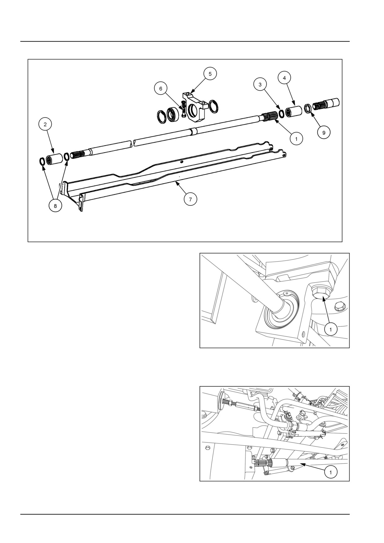
Four-Wheel Drive (4WD) system - Drive shaft
Drive shaft - Install
GNIL15TR01128FA
1
1. Tighten the bolts (1) on the center mounting bracket of
the Four-Wheel Drive (4WD) shaft.
GNIL15TR01129AA
2
2. Engage the spline coupler (2), figure 1, on the Power
Take-Off (PTO) shaft of the front axle and the 4WD
shaft.
3. Push the 4WD shaft (1) toward the front axle.
GNIL15TR01130AA
3
23.1 [23.314] / 4
Four-Wheel Drive (4WD) system - Drive shaft
4. Seat the retaining rings (8), figure 1, on the front axle
PTO shaft and 4WD shaft.
5. Seat the retaining ring (1) on the PTO shaft of the drop
box.
GNIL15TR01130AA
4
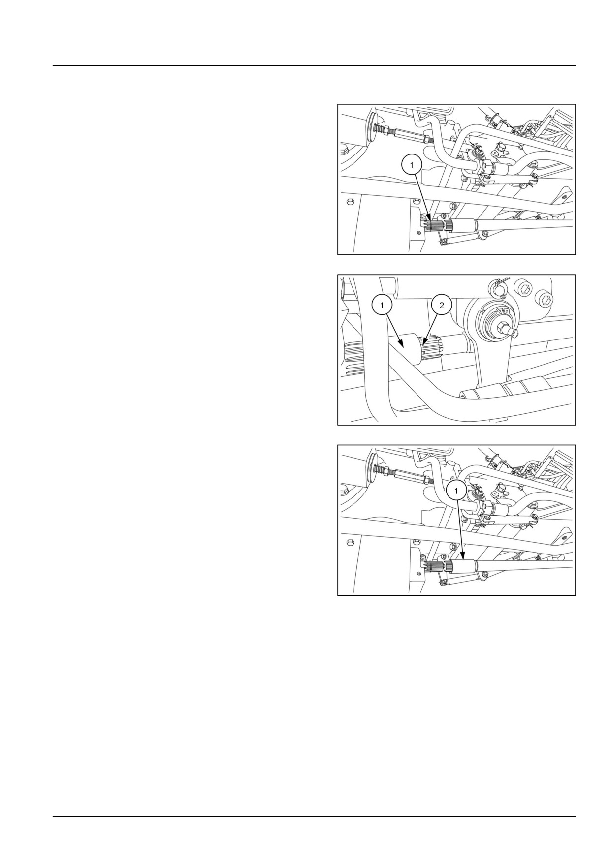
6. Slide the spline coupler (1) toward the drop box.
7. Measure the gap (2) on the 4WD shaft between retain-
ing ring groove and sleeve face.
GNIL15TR01131AA
5
8. Slide the spline coupler (1) away from the drop box.
GNIL15TR01130AA
6
9. Insert suitable shim or combination of shims (9), figure
1, on the drop box PTO shaft to make up for the gap.
Maintain a free play of 0.3 mm.
10. Slide the spline coupler toward the drop box and seat
the retaining ring (3), figure 1.
23.1 [23.314] / 5

Four-Wheel Drive (4WD) system - Drive shaft
11. Fit the drive shaft guard and tighten the bolts (1) on
both the ends.
GNIL14TR00823AA
7
23.1 [23.314] / 6
Index
Four-Wheel Drive (4WD) system - 23
Drive shaft - 314
Drive shaft - Install
4
Drive shaft - Remove
3
23.1 [23.314] / 7
CNH Industrial America New Holland Site 100 Brubaker Avenue New Holland, Pennsylvania United States
17557
SERVICE - Technical Publications & Tools
PRINTED IN U.S.A.
All rights reserved. No part of the text or illustrations of this publication may be reproduced.
NEW HOLLAND policy is one of continuous improvement and the right to change prices, specification or equipment
at any time without notices is reserved.
All data given in this publication is subject to production variations. Dimensions and weight are approximate only and
the illustrations do not necessarily show products in standard condition. For exact information about any particular
product, please consult your NEW HOLLAND Dealer.
EN