New Holland Tractor Workmaster 50 / Workmaster 60 / Workmaster 70 / Tier 4B (final). SERVICE MANUAL - page 3
Clutch - Clutch mechanical release control
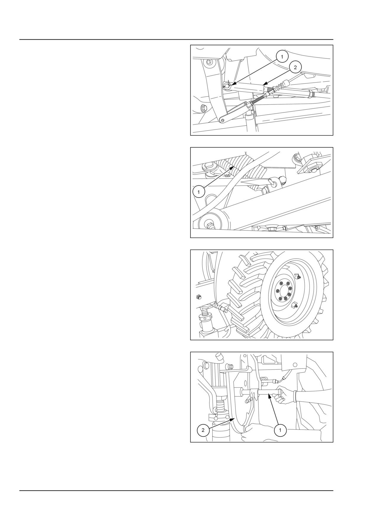
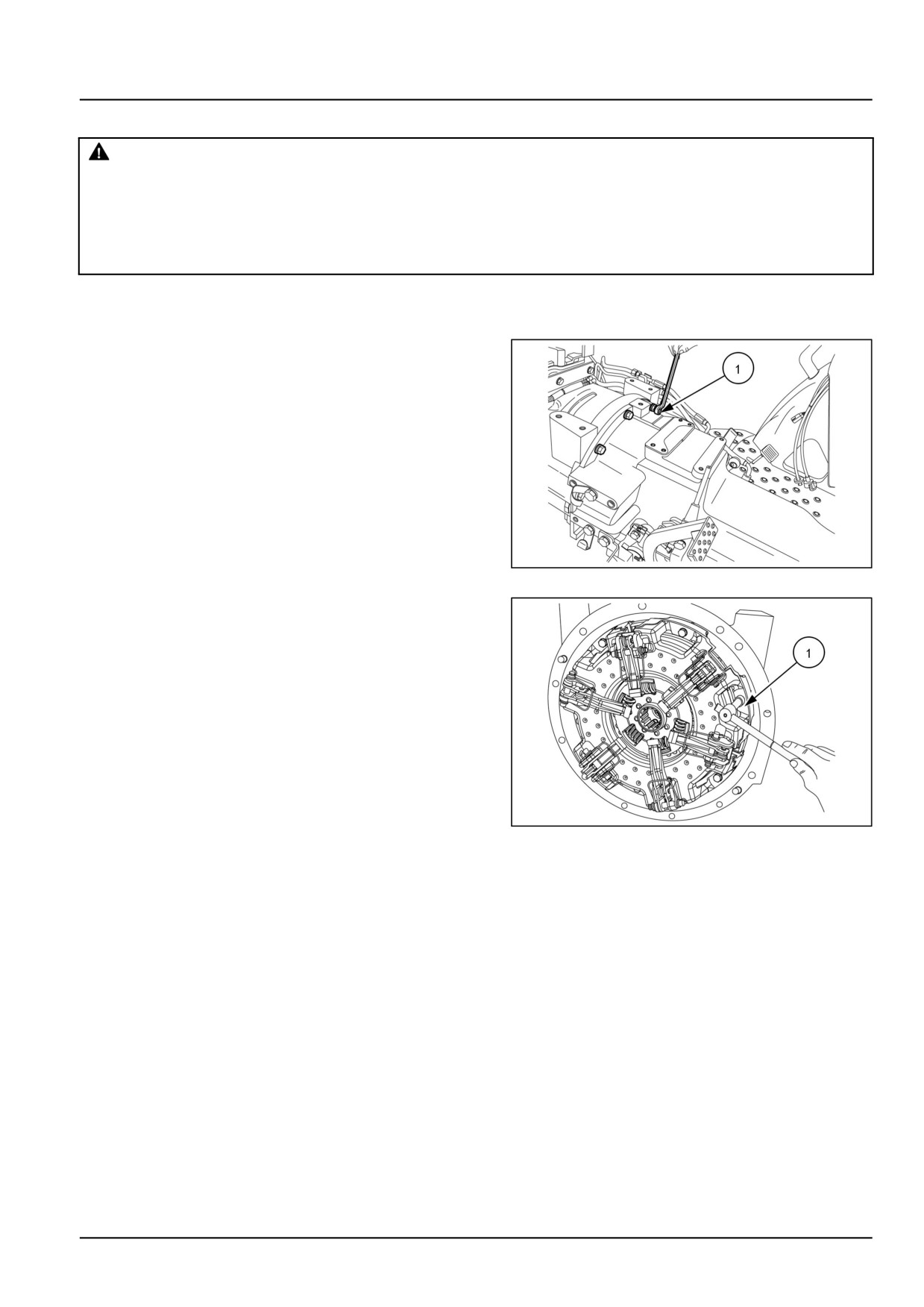
8. Remove split pin (1).
9. Disconnect linkage (2) from clutch cross shaft.
GNIL14TR00781AA
4
10. Similarly remove brake pedal spring (2) and discon-
nect all the linkages.
GNIL14TR00782AA
5
11. Jack-up rear left-hand side of tractor and remove
left-hand side rear wheel.
GNIL14TR04667AB
6
12. Pull out clutch or brake pedal support rod (1) from
the rear axle housing.
13. Retrieve clutch pedal (2) from the support shaft.
GNIL14TR04668AB
7
18.1 [18.100] / 4
Clutch - Clutch mechanical release control
Power Take-Off (PTO) clutch lever removal
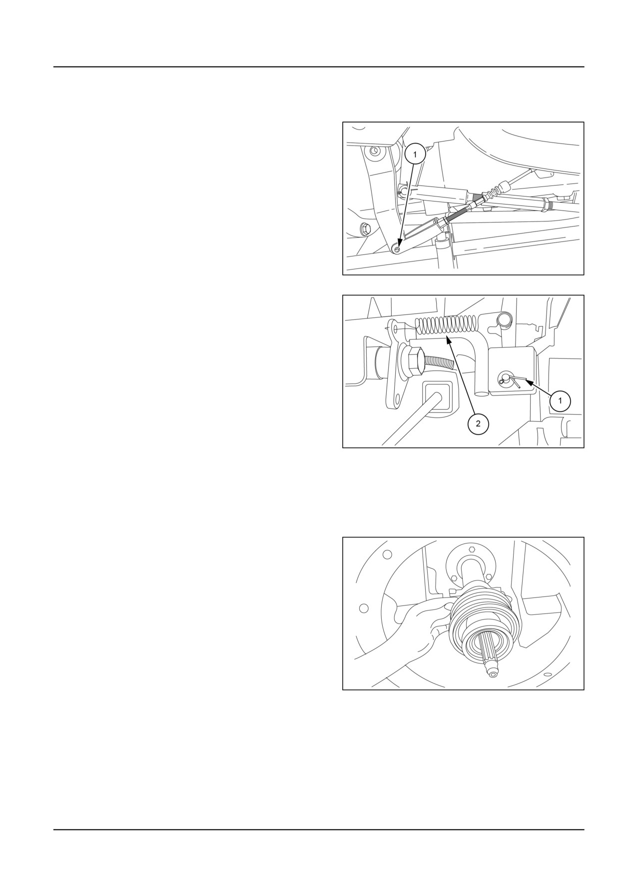
To remove the Power Take-Off (PTO) clutch lever (1)
proceed as follows:-
1. Remove pin (1) by releasing lock plate and dis-
connect linkage between Power Take-Off (PTO) clutch
lever and Power Take-Off (PTO) clutch cross shaft.
GNIL14TR00781AA
8
2. Remove the split pin lock (1) take out the pin and
remove hand lever from the mounting bracket.
3. Remove bolt (2) from the housing to take out the
levers with the bracket.
GNIL14TR04671AB
9
Cross shafts removal
To remove cross shafts clutch housing has to be split
between engine flywheel housing and transmission
housing.
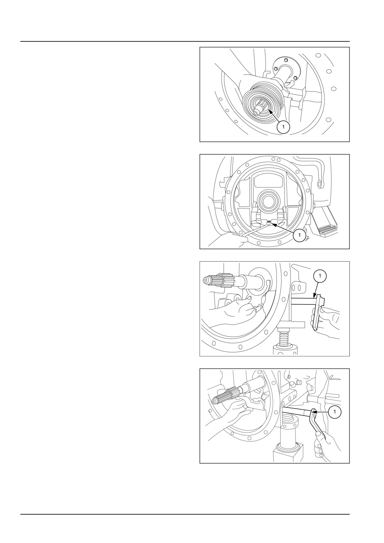
1. Remove clips (1) from both the forks and release
bearings and take out release bearings.
GNIL14TR04673AB
10
18.1 [18.100] / 5
Clutch - Clutch mechanical release control
2. Slide out both transmission and Power Take-Off
(PTO) clutch release bearings (1) and (2) from the shaft.
GNIL14TR04674AB
11
3. Loosen the Power Take-Off (PTO) clutch fork lock
screw (1).
GNIL14TR04675AB
12
4. Pull out the Power Take-Off (PTO) cross shaft (1)
from left hand-side of transmission housing and retrieve
fork from the housing.
GNIL14TR04677AB
13
5. Loosen the transmission clutch fork screw.
6. Pull out the Transmission clutch cross shaft (1) from
left-hand side of the transmission housing and retrieve
fork from the housing.
GNIL14TR04676AB
14
18.1 [18.100] / 6

Clutch - Clutch mechanical release control
Clutch mechanical release control - Install
Reassemble the clutch mechanical release control.
Take care of the following:
1. Reassembly follows the disassembly procedure in re-
verse.
2. Make sure that the lock clips are properly seated on the
clutch release forks.
3. Comply with tightening torques indicated. See Clutch
- Torque (18.110).
GNIL14TR04673AB
1
4. Apply LOCTITE® 243™ sealant to clutch release fork
lock-screw and left-hand side brake pedal lock-screw
before tightening.
5. Thoroughly clean and degrease mating surfaces of en-
gine and transmission housing. Apply a bead of liquid
gasket of approximately 2.000 mm (0.079 in) of diam-
eter. Buckle up the transmission housing and the en-
gine.
18.1 [18.100] / 7
Clutch - Clutch mechanical release control
Clutch mechanical release control - Adjust
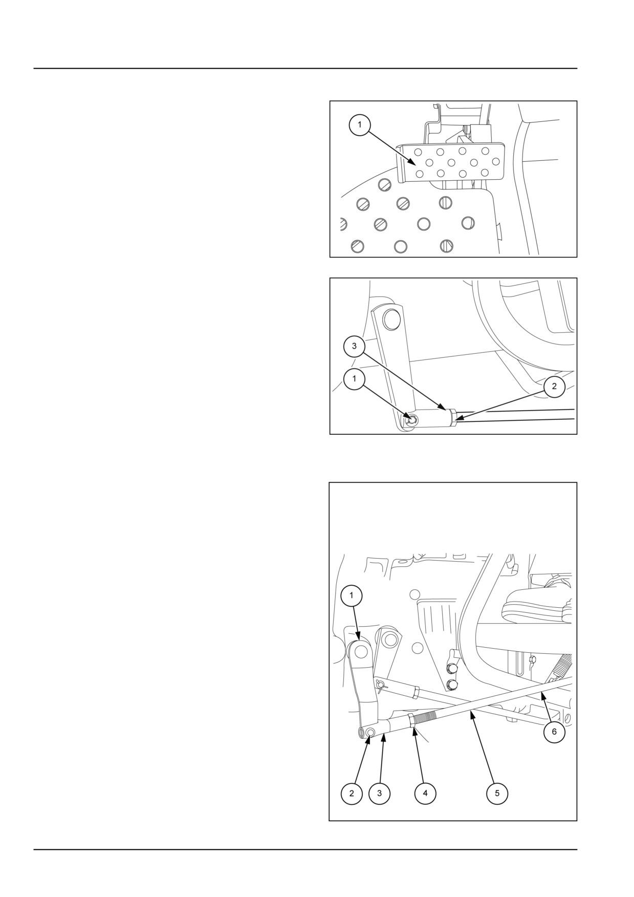
Clutch pedal free play should be 30.00 - 45.00 mm
(1.18 - 1.77 in). To adjust the clutch pedal free play
proceed as follows:
GNIL14TR04687AA
1
1. Remove the split pin (1) and disconnect the linkage.
2. Loosen the lock nut (2).
3. Rotate the yoke (3) clockwise to reduce the play and
anti-clockwise to increase the play.
4. Connect the linkage back to the cross shaft.
GNIL14TR04688AB
2
Power Take-Off (PTO) clutch lever free play (double speed )
1. Remove the pin (2), fork (3) and rod (5) separately.
2. Keep lever (1) at the right most position such that the
bearing just touches the clutch fingers.
3. Insert rod (5) into fork (6) and tight the threads up to
15.00 mm (0.59 in).
4. Keep end of lever (7) at 30.00 - 35.00 mm (1.18 -
1.38 in) from edge as shown in figure.
5. Keep the rod in static position and insert fork (3) into
rod (5).
6. Match the hole of fork (3) with hole of lever (1). Keep
the lever in initial position.
7. Insert pin (2) in matching holes and lock lever (1).
GNIL14TR04690FB
3
18.1 [18.100] / 8
Clutch - Clutch mechanical release control
8. Now tight the nut (4) to lock the fork.
9. We can see the play of lever (7) between edge A and
end of lever at 30.00 - 35.00 mm (1.18 - 1.38 in) from
edge A. This is the free play of Power Take-Off (PTO)
clutch lever.
18.1 [18.100] / 9
Index
Clutch - 18
Clutch mechanical release control - 100
Clutch mechanical release control - Adjust
8
Clutch mechanical release control - Install
7
Clutch mechanical release control - Remove
3
18.1 [18.100] / 10
Clutch - 18
Clutch and components - 110
Workmaster™ 50
Workmaster™ 60
Workmaster™ 70
18.2 [18.110] / 1
Contents
Clutch - 18
Clutch and components - 110
TECHNICAL DATA
Clutch
General specification
3
Torque
3
Special tools
4
Sealing
4
FUNCTIONAL DATA
Clutch
Dynamic description
6
Sectional view
7
SERVICE
Clutch
Remove
9
Disassemble
10
Inspect
13
Assemble
15
Adjust
16
Service instruction
17
Clutch control mechanism
Remove
18
DIAGNOSTIC
Clutch
Troubleshooting
20
18.2 [18.110] / 2
Clutch - Clutch and components
Clutch - General specification
Type
Dry plate torsion springs
Control
Mechanical pedal for transmission
Hand lever for PTO
Release mechanism
Diaphragm type
Plate material
Cerametallic
Plate thickness
7.50 - 8.10 mm (0.30 - 0.32 in)
Plate with pressure springs
Tangential springs
Clutch - Torque
Description
Thread Size (mm)
Torque
Transmission housing to flywheel
M12 X 1.25
7.00 kgf (15.43 lbf)
housing buckle up bolts (C1)
Clutch assembly mounting bolts (C2)
M8 X 1
2.60 kgf (5.73 lbf)
Bolts, release fork (C3)
M16 X 1.5
16.00 kgf (35.27 lbf)
18.2 [18.110] / 3
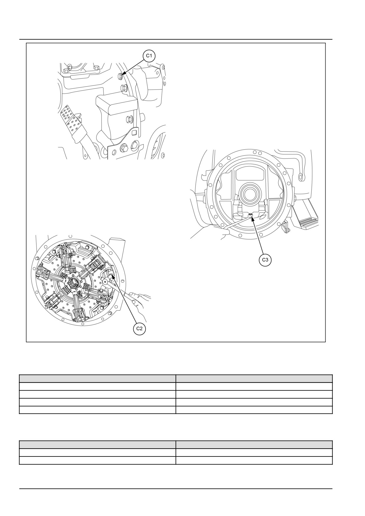
Clutch - Clutch and components
GNIL14TR00801GA
1
Clutch - Special tools
Tool Description
Tool Number
Clutch centralizer and finger height setting gauge
380000612
Clutch finger height adjusting wrench (set of three)
380000256
Installer, oil seal in clutch housing
84261387
Installer, oil seal in hollow shaft
84261388
Clutch - Sealing
Operation description
Sealant specification
Engine to transmission buckle up (S1)
LOCTITE® 518™
Bolts, release fork (S2)
LOCTITE® 243™
18.2 [18.110] / 4
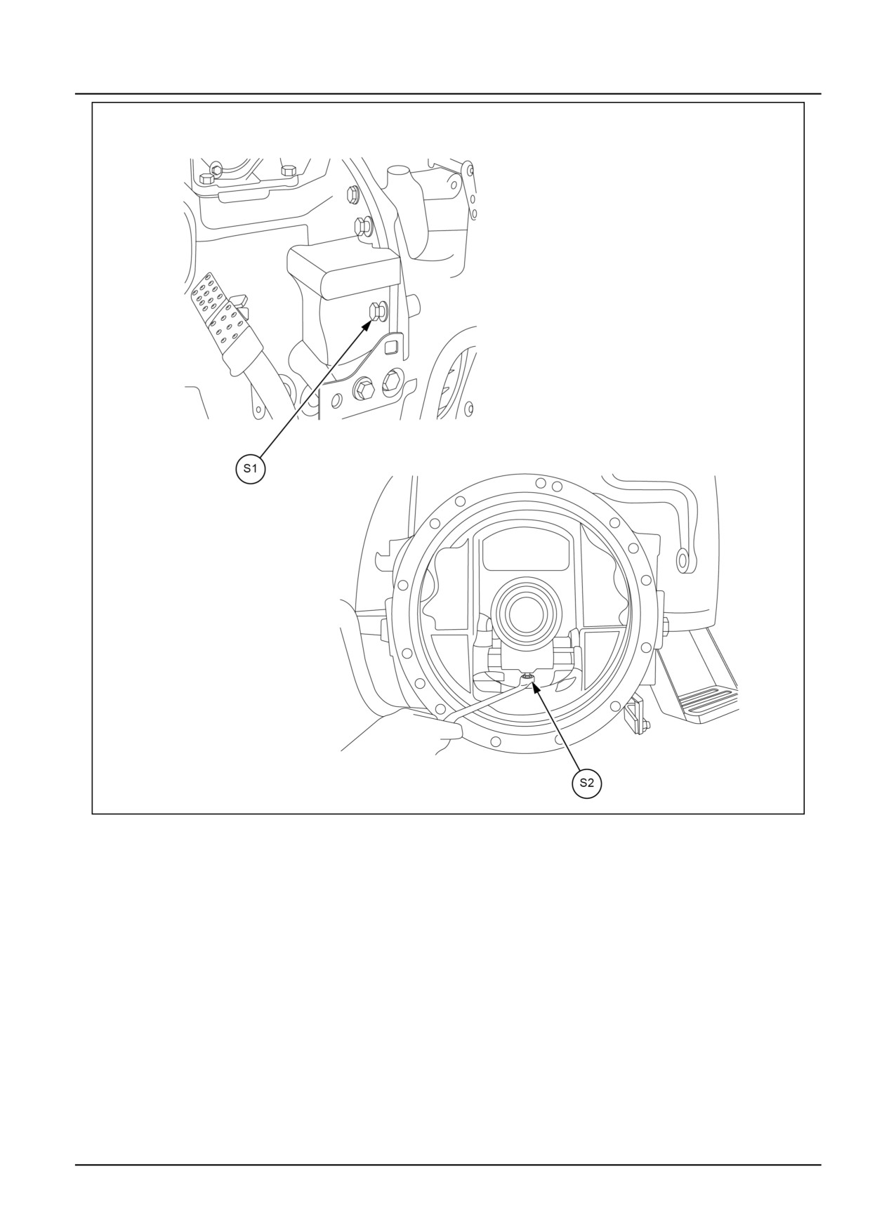
Clutch - Clutch and components
GNIL14TR04659GB
1
18.2 [18.110] / 5
Clutch - Clutch and components
Clutch - Dynamic description
The clutch system is double clutch mechanical type. It includes two dry clutch discs with non-asbestos, organic ma-
terial pads. One clutch disc is to connect transmission to engine and another for connecting PTO directly to engine,
independent of transmission.
The clutch is located in front of the transmission. The transmission (main) clutch is operated by means of foot pedal
and PTO clutch is operated by hand lever located on right side below rear hood panel. The clutch system is composed
of the clutch housing, clutch pressure plate, disc ring, clutch release fingers, clutch release bearings and clutch discs.
OPERATION
When both the clutches are engaged, the PTO clutch pressure plate pushes the PTO clutch disc against engine
flywheel and transmission pressure plate pushes the clutch housing by the spring action of dish ring.
The friction between the clutch disc, flywheel and clutch housing transmits the engine power to the transmission drive
shaft and PTO drive shaft independently.
The clutch pedal is connected to the main clutch release bearing by means of mechanical linkage components.
When the clutch pedal is pressed, the clutch release bearing moves forward and discharges the main clutch fingers.
Consequently, the clutch pressure plate backs off and releases the clutch disc from the clutch housing. The transfer
of engine power to the transmission is stopped.
When the clutch pedal is released, the main clutch release bearing disengages the main clutch finger which acts on the
clutch pressure plate and causes the clutch housing, main clutch discs and pressure plates to come in contact. The
flow of power from the engine and transmission is re-established. Similarly PTO clutch is engaged and disengaged
independent of transmission clutch by operating PTO clutch control lever.
18.2 [18.110] / 6
Clutch - Clutch and components
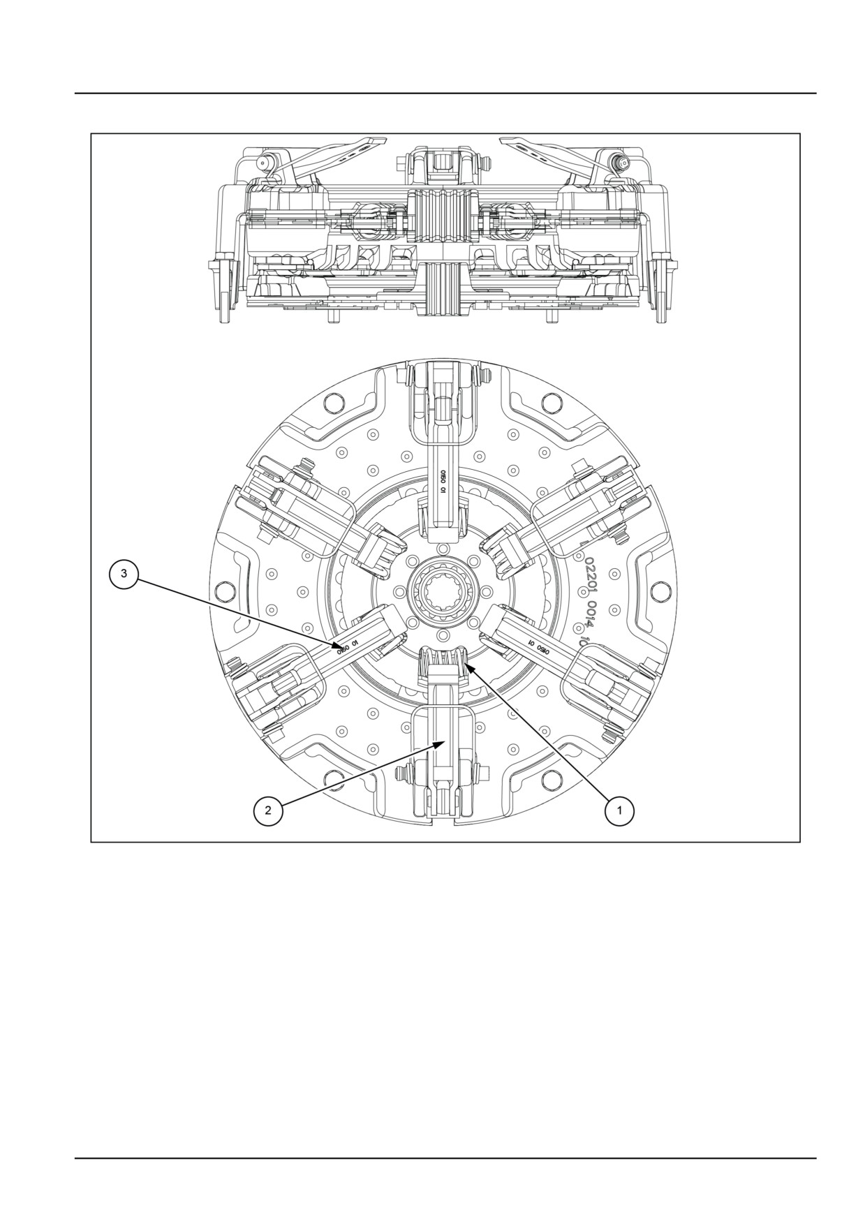
Clutch - Sectional view
GNIL14TR00802GA
1
(1) — Damper springs
(3) — Power Take-Off (PTO) clutch release fingers
(2) — Transmission clutch release fingers
18.2 [18.110] / 7
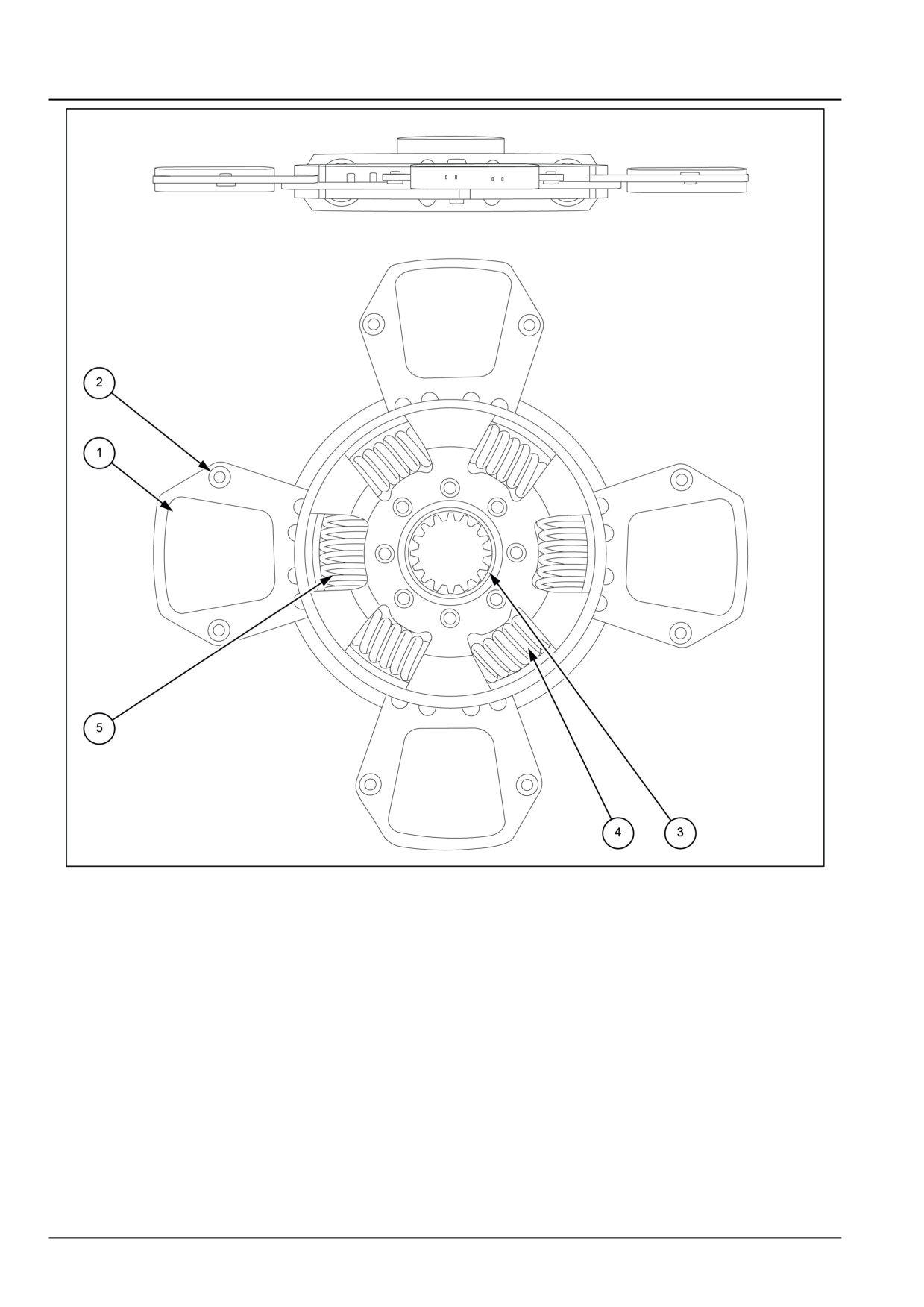
Clutch - Clutch and components
GNIL14TR00803GA
2
(1) - Clutch facing
(4) - Idle damper spring
(2) - Facing rivet
(\5) - Main damper spring
(3) - Hub
18.2 [18.110] / 8
Clutch - Clutch and components
Clutch - Remove
WARNING
Avoid injury!
Handle all parts carefully. Do not place your hands or fingers between parts. Use Personal Protec-
tive Equipment (PPE) as indicated in this manual, including protective goggles, gloves, and safety
footwear.
Failure to comply could result in death or serious injury.
W0208A
It is necessary to split the tractor between engine and
transmission housing to gain access to the clutch.
1. Remove the bolts (1).
2. Separate the transmission housing from engine. See
engine removal section.
GNIL14TR00753AA
1
3. Remove the bolts (1) which retains the clutch assem-
bly to the engine fly wheel and slacken the two remain-
ing bolts.
GNIL14TR00754AA
2
4.
Insert centralizing pin special tool number
380000612 in clutch plate shaft seats back off the two
remaining bolts.
5. Remove the assembly completely.
6. Retrieve the Power Take-Off (PTO) clutch disc.
18.2 [18.110] / 9
Clutch - Clutch and components
Clutch - Disassemble
WARNING
Avoid injury!
Handle all parts carefully. Do not place your hands or fingers between parts. Use Personal Protec-
tive Equipment (PPE) as indicated in this manual, including protective goggles, gloves, and safety
footwear.
Failure to comply could result in death or serious injury.
W0208A
1. Remove the clutch assembly from the tractor as de-
scribed earlier in this section. See Clutch - Remove
(18.110).
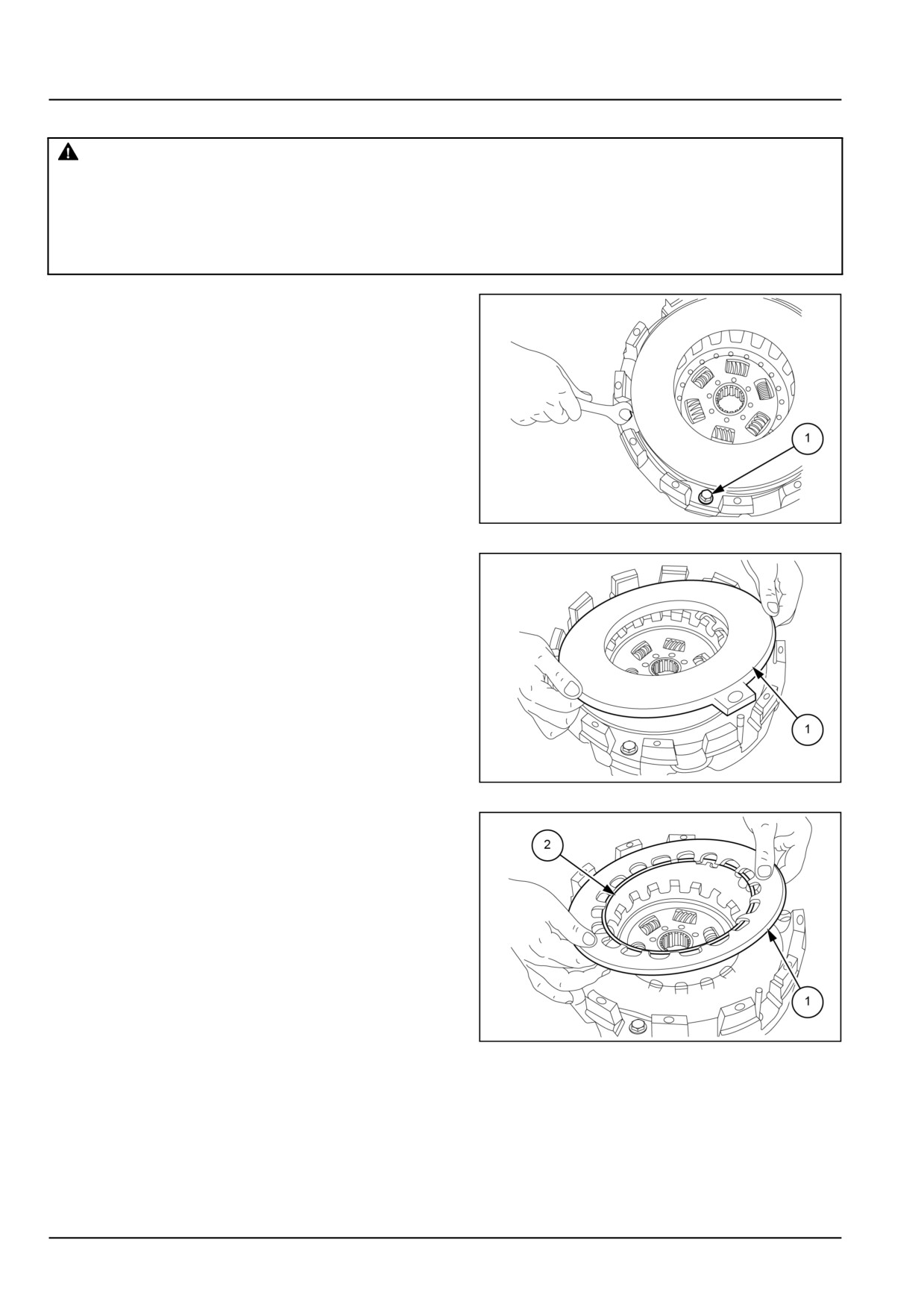
2. Loosen the Power Take-Off (PTO) clutch release lever
locknuts (1).
NOTICE: Since the locknuts are under the load of disk ring,
loosen all these gradually and evenly by rotating 1/4 to 1/2
turns.
GNIL14TR04695AB
1
3. Remove Power Take-Off (PTO) pressure plate (1).
GNIL14TR04696AB
2
4. Remove disk ring (1) and lock ring (2).
GNIL14TR04697AB
3
18.2 [18.110] / 10
Clutch - Clutch and components
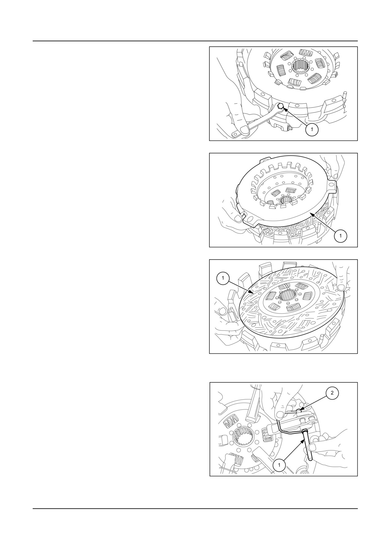
5. Loosen lock nut (1).
GNIL14TR04698AB
4
6. Remove transmission clutch pressure plate (1).
GNIL14TR04699AB
5
7. Remove transmission clutch disc (1) from the housing.
GNIL14TR04700AB
6
Release fingers disassembly
8. Push out the pin (1) from the housing and retrieve the
spring (2).
GNIL14TR04702AB
7
18.2 [18.110] / 11

Clutch - Clutch and components
9. Remove release fingers from the housing.
GNIL14TR04703AA
8
18.2 [18.110] / 12
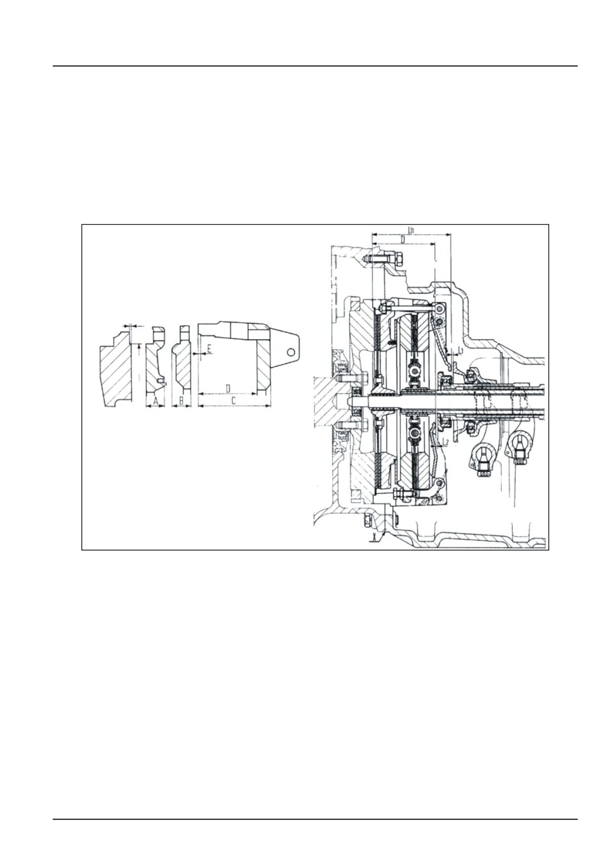
Clutch - Clutch and components
Clutch - Inspect
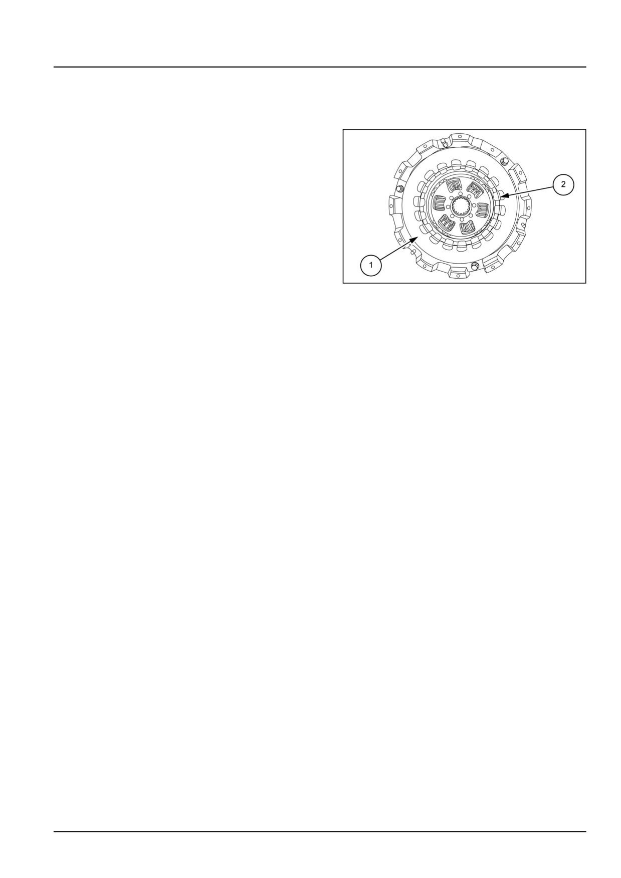
1. Check clutch driven discs for wear and replace if rivets
(2) are near or flush with top facing.
2. Discs are also to be replaced if the organic facings are
found to be soaked with oil.
3. Check condition of clutch housing and pressure plate
friction surfaces. If necessary dress noting that dimen-
sions of pressure plates and clutch housing must not
be reduced below the limits described below otherwise
replace as necessary.
20097548
1
18.2 [18.110] / 13
Clutch - Clutch and components
See 1.
•
Fly wheel (1) under cut - ‘A’ = 2.000 mm (0.079 in)
•
Power Take-Off (PTO) clutch pressure plate (2)
thickness - ‘B’ = 22.000 mm (0.866 in)
•
Transmission clutch pressure plate (3) thickness - ‘C’
= 24.000 mm (0.945 in)
•
Clutch housing under cut -‘E’ = 2.500 mm (0.098 in)
•
Dressing allowance - ‘F’ = 70.000 - 70.150 mm
(2.760 - 2.760 in)
•
Calculate dimension ‘F’ as follows
F=A+B+C+S1+S2+P
Where,
S1 = Power Take-Off (PTO) clutch disc thickness
S2 = Transmission clutch disc thickness
P = Spring dimensions to restore original load =
4.500 mm (0.180 in) (fixed)
•
Check that value ‘F’ is equal to 69.850 - 70.150 mm
(2.750 - 2.760 in)
•
In restoring value ‘F’ check that clutch housing thick-
ness ‘E’ does not fall below 17.000 mm (0.670 in)
i.e. D-F = E ≥ 17.000 mm (0.670 in)
•
Check that the undercut ‘E’ on clutch housing is
deeper than 2.500 mm (0.098 in) and restore as
necessary.
•
If necessary, dress friction face on flywheel and re-
store external undercut ‘A’ of 2.000 mm (0.079 in).
18.2 [18.110] / 14
Clutch - Clutch and components
Clutch - Assemble
Re-assembly follows disassembly procedure in reverse
order. See Clutch - Disassemble (18.110) .
1. Position disc springs (1) correctly and lock-ring (2) on
transmission pressure plates as shown in 1.
GNIL14TR04706AB
1
2. Use special tool number 380000612, and centralize the
clutch discs.
3. Install the clutch assembly on flywheel.
4. Adjust the release fingers as described under clutch
release finger settings. See Clutch - Adjust (18.110).
18.2 [18.110] / 15
Clutch - Clutch and components
Clutch - Adjust
For correct function of clutch release mechanism, the
release fingers must be set at the distances D - 96 mm
(4 in) and D1 - 121 mm (5 in) relative to flywheel face
for transmission clutch and Power Take-Off
(PTO)
clutch respectively.
Follow the below described procedure to obtain these
settings.
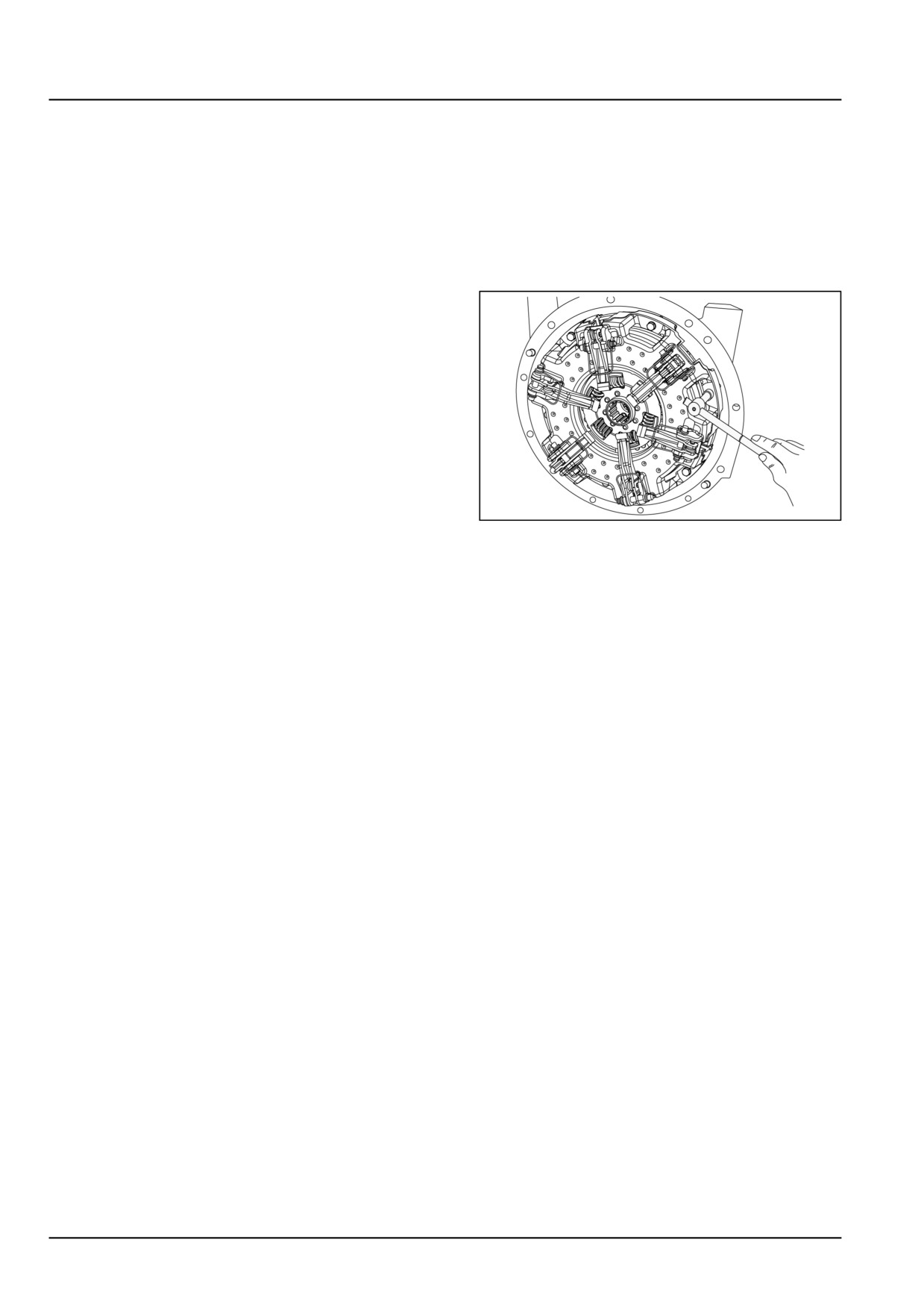
1. Install the clutch assembly on engine flywheel.
GNIL14TR00754AA
1
2. Insert centralizer pin, special tool number 380000612,
along with fingers height setting gauge drive shaft seats
ensuring that end is in contact with flywheel housing.
3. First set Power Take-Off (PTO) release fingers by us-
ing height setting gauge as shown in figure. Gap be-
tween gauge and finger should be between 0.30 mm
(0.01 in). Use feeler gauge to check the gap.
4. Use special tool no. 9971365. Rotate the locknut and
set the gap.
5. Similarly set the height setting gauge as shown in
the figure (b) to set transmission clutch release fin-
gers. The gap between fingers and gauge should be
0.30 mm (0.01 in).
6. Use special tool number 9971365. Loosen the locknut
and rotating screws and adjust the gap.
18.2 [18.110] / 16
Clutch - Clutch and components
Clutch - Service instruction
WARNING
Avoid injury!
Handle all parts carefully. Do not place your hands or fingers between parts. Use Personal Protec-
tive Equipment (PPE) as indicated in this manual, including protective goggles, gloves, and safety
footwear.
Failure to comply could result in death or serious injury.
W0208A
Important points to be taken into account while replac-
ing clutch:
1. Check the condition of spigot bearing replace if neces-
sary.
2. Check the condition of the oil seals on the engine and
transmission sides for leaks and replace if necessary.
3. Check the flywheel face is free from scores and cracks.
When machining the surface, follow specified toler-
ances.
NOTE: Machine the bolting surface to the same amount of
the running surface, to maintain original clamp loads.
Always use suitable tools to align holes. Do not use hands
or fingers.
4. Make sure that the alignment of the clutch cover
to the flywheel is correct. Use special tool number
380000612 for alignment.
5. Make sure that the clutch cover is secured to the fly-
wheel evenly and sequentially. Use new spring wash-
ers.
6. After an initial running-in period, any variation lever
height will correct itself.
7. Before fitting check the clutch plate for lateral runout.
8. Make sure that the clutch plate is fitted the correct way.
Observe the direction as indicated on the driven plate.
9. Check the gearbox input shaft for damage. Only non-
metallic based high melting point grease should be
used to lubricate the splines and release bearing guide
sleeve.
10. Check the release bearing guide sleeve for wear and
replace if necessary.
11. After applying the grease to the gearbox input shaft,
guide the clutch driven plate on to the shaft and re-
move the surplus grease.
12. Make sure that the alignment between the engine and
transmission/clutch housing is correct. Make sure that
the locating dowels are fit and secure.
13. Carefully guide the input shaft into the clutch hub
splines. Do not allow the weight of the transmission to
hang on the hub of the driven plate. This will prevent
irreparable damage to the segments and associated
cushion springs.
14. Make sure that the adjustment of clutch pedal free play
is correct.
18.2 [18.110] / 17
Clutch - Clutch and components
Clutch control mechanism - Remove
WARNING
Avoid injury!
Handle all parts carefully. Do not place your hands or fingers between parts. Use Personal Protec-
tive Equipment (PPE) as indicated in this manual, including protective goggles, gloves, and safety
footwear.
Failure to comply could result in death or serious injury.
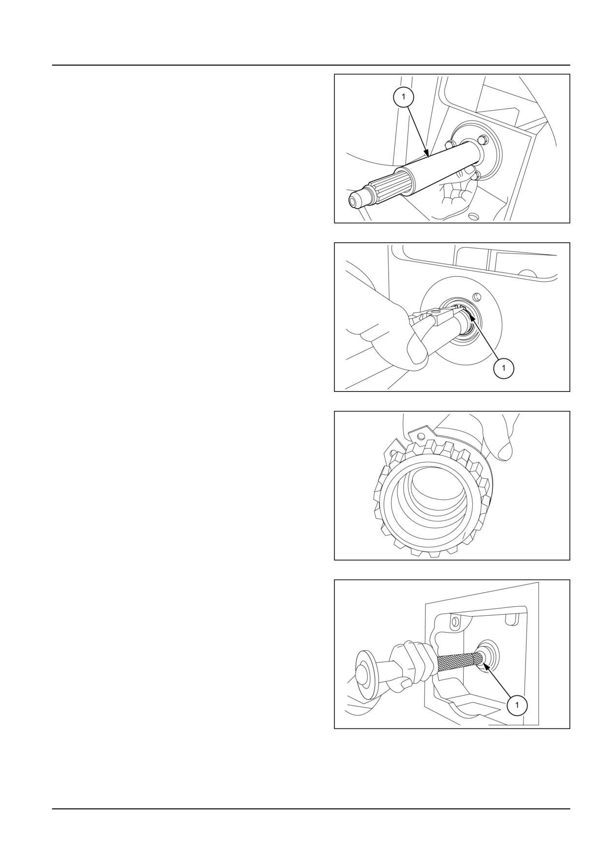
W0208A
It is necessary to split the tractor between engine and
transmission housing to gain access to the clutch.
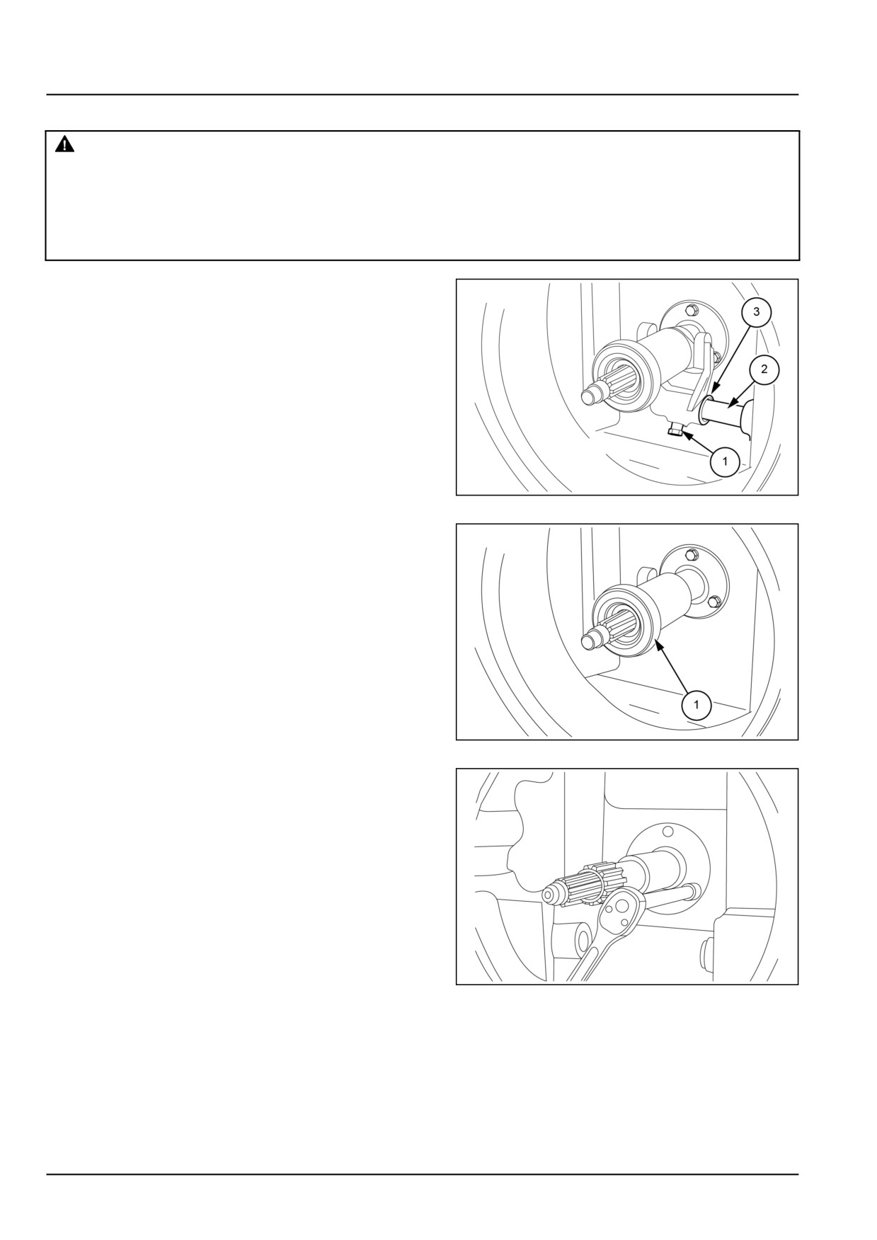
1. Loosen the set screw (1) from fork.
2. Pull out the cross shaft (2).
3. Remove clutch release fork (3).
GNIL14TR04679AB
1
4. Slide out the clutch release bearing (1).
GNIL14TR04680AB
2
5. Loosen the bolts 3 numbers as shown in figure.
GNIL14TR04681AA
3
18.2 [18.110] / 18
Clutch - Clutch and components
6. Unscrew bolts as shown in figure and remove top cover
(1).
GNIL14TR04682AB
4
7. Remove lock (1) as shown in figure. Use plastic ham-
mer to push out the shaft. The shaft will come out to-
ward gearbox side. Retrieve bearing.
GNIL14TR04683AB
5
8. To remove shaft (2) toward the clutch side, remove cir-
clip lock (1). Retrieve bearing and seal.
GNIL14TR04684AA
6
9. Use special tool number 84261387 and install the seal
(1).
GNIL14TR04685AB
7
18.2 [18.110] / 19
Clutch - Clutch and components
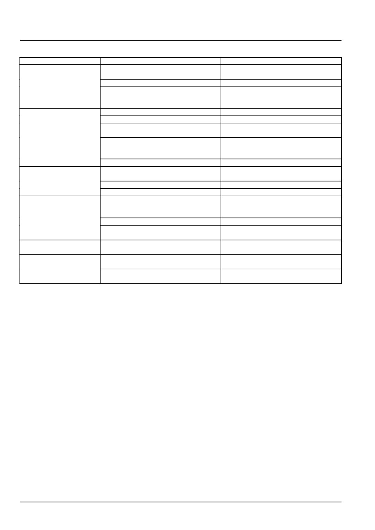
Clutch - Troubleshooting
Problem
Possible Cause
Correction
Clutch slips
Clutch disc, pressure plate and/or flywheel
Replace clutch disc; replace clutch if nec-
wear.
essary and grind the flywheel.
Damaged or bent or broken fingers.
Replace finger assembly.
Oil or grease on friction material.
Replace clutch disc; repair leak of lubricant
in to clutch housing; thoroughly clean fric-
tion surfaces.
Clutch grabs
Stiff external control linkage.
Check and lubricate linkage pivot points.
Warped clutch disc.
Replace clutch disc.
Clutch disc with damaged damper springs
Replace clutch disc.
or loose hub.
Oil or grease on friction material.
Replace clutch disc; repair leak of lubricant
in to clutch housing; thoroughly clean fric-
tion surfaces.
Finger springs broken.
Replace finger springs.
Clutch fails to disconnect
Warped clutch disc.
Replace clutch disc.
and drags
Damaged clutch release bearing.
Replace clutch release bearing.
Damaged finger spring.
Replace finger springs.
Clutch noise at
Warped clutch disc.
Replace clutch disc.
engagement and / or
disengagement
Damaged clutch disc damper springs.
Replace clutch disc.
Excess backlash on clutch disc to hub
Replace clutch disc and shaft, as neces-
meshing splines.
sary.
Clutch noise at
Worn clutch release bearing.
Replace bearing.
disengagement
Clutch control pedal
Hard pedal.
Check and lubricate linkage.
hardness
Broken or disconnected clutch return
Repalce or hook-up clutch return spring.
spring.
18.2 [18.110] / 20
Index
Clutch - 18
Clutch and components - 110
Clutch - Adjust
16
Clutch - Assemble
15
Clutch - Disassemble
10
Clutch - Dynamic description
6
Clutch - General specification
3
Clutch - Inspect
13
Clutch - Remove
9
Clutch - Sealing
4
Clutch - Sectional view
7
Clutch - Service instruction
17
Clutch - Special tools
4
Clutch - Torque
3
Clutch - Troubleshooting
20
Clutch control mechanism - Remove
18
18.2 [18.110] / 21
CNH Industrial America New Holland Site 100 Brubaker Avenue New Holland, Pennsylvania United States
17557
SERVICE - Technical Publications & Tools
PRINTED IN U.S.A.
All rights reserved. No part of the text or illustrations of this publication may be reproduced.
NEW HOLLAND policy is one of continuous improvement and the right to change prices, specification or equipment
at any time without notices is reserved.
All data given in this publication is subject to production variations. Dimensions and weight are approximate only and
the illustrations do not necessarily show products in standard condition. For exact information about any particular
product, please consult your NEW HOLLAND Dealer.
EN
SERVICE MANUAL
Transmission
Workmaster™ 50
Workmaster™ 60
Workmaster™ 70
21
Contents
Transmission - 21
[21.114] Mechanical transmission
21.1
[21.130] Mechanical transmission external controls
21.2
[21.140] Mechanical transmission internal components
21.3
[21.145] Gearbox internal components
21.4
[21.200] Dropbox
21.5
21
Transmission - 21
Mechanical transmission - 114
Workmaster™ 50
Workmaster™ 60
Workmaster™ 70
21.1 [21.114] / 1
Contents
Transmission - 21
Mechanical transmission - 114
TECHNICAL DATA
Mechanical transmission
General specification
3
Torque
3
Sealing
5
Special tools
6
FUNCTIONAL DATA
Mechanical transmission
Sectional view
7
Overview
9
SERVICE
Mechanical transmission
Drive shaft - Service instruction
12
Remove
14
Disassemble - Intermediate plate
18
Inspect - Intermediate plate
21
Assemble - Intermediate plate
22
Install
25
DIAGNOSTIC
Mechanical transmission
Troubleshooting
29
21.1 [21.114] / 2
Transmission - Mechanical transmission
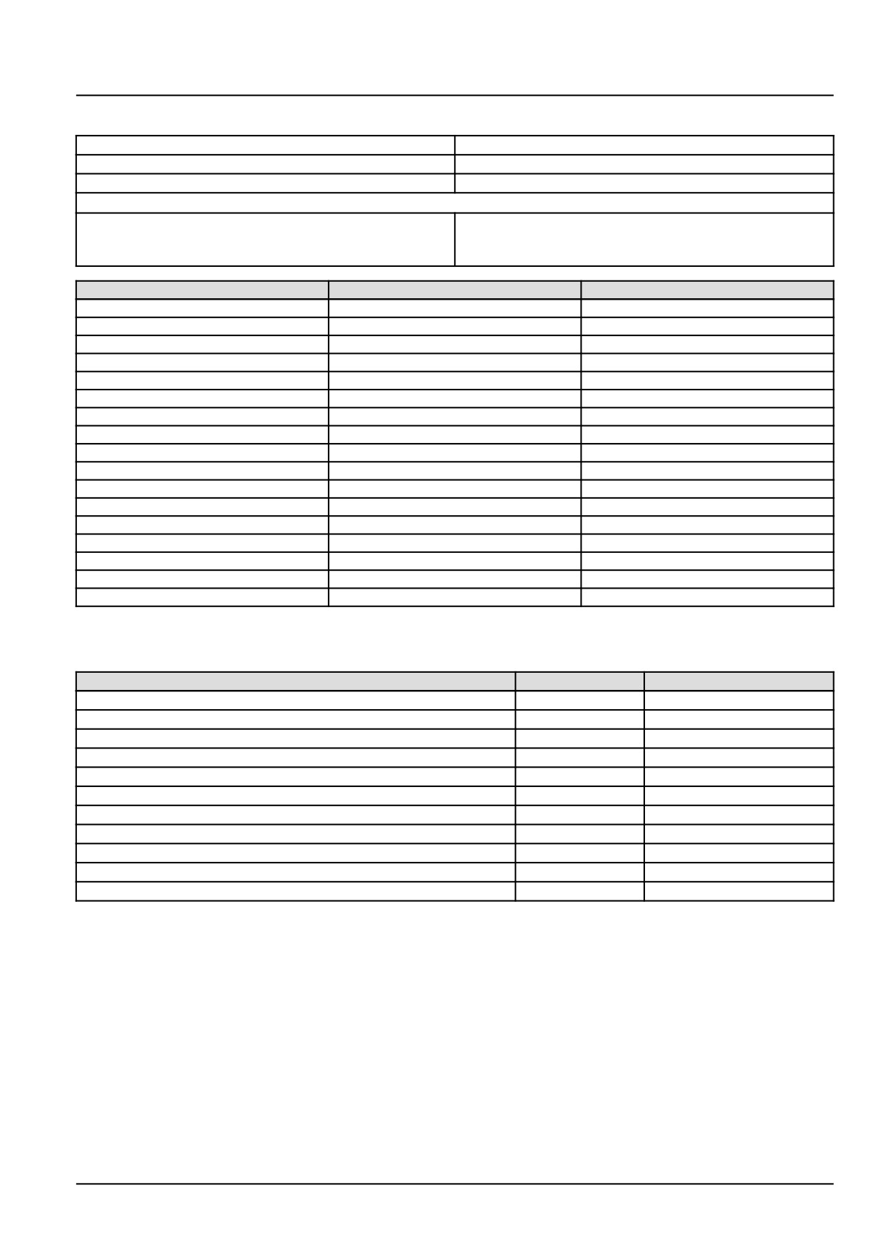
Mechanical transmission - General specification
Gear box type
Constant mesh
Range gears
Constant mesh
Forward-reverse
Mechanical Synchromesh Shuttle
Lubrication
Transmission oil capacity
APGL4SAE 20W30 23 L (6 US gal) for 2WD (Two Wheel
Drive) and 25.0 L (6.6 US gal) for 4WD (Four Wheel
Drive)
Rear Tire Size
13.6-28
14.9-28
Gear
2600 RPM
2600 RPM
FL1
2.56
2.73
FL2
3.86
4.11
FL3
5.69
6.07
FL4
7.83
8.34
FH1
10.03
10.68
FH2
15.10
16.09
FH3
22.29
23.75
FH4
30.67
32.68
RL1
2.70
2.88
RL2
4.07
4.34
RL3
6.01
6.41
RL4
8.27
8.82
RH1
10.59
11.29
RH2
15.96
17.00
RH3
23.56
25.10
RH4
32.40
34.53
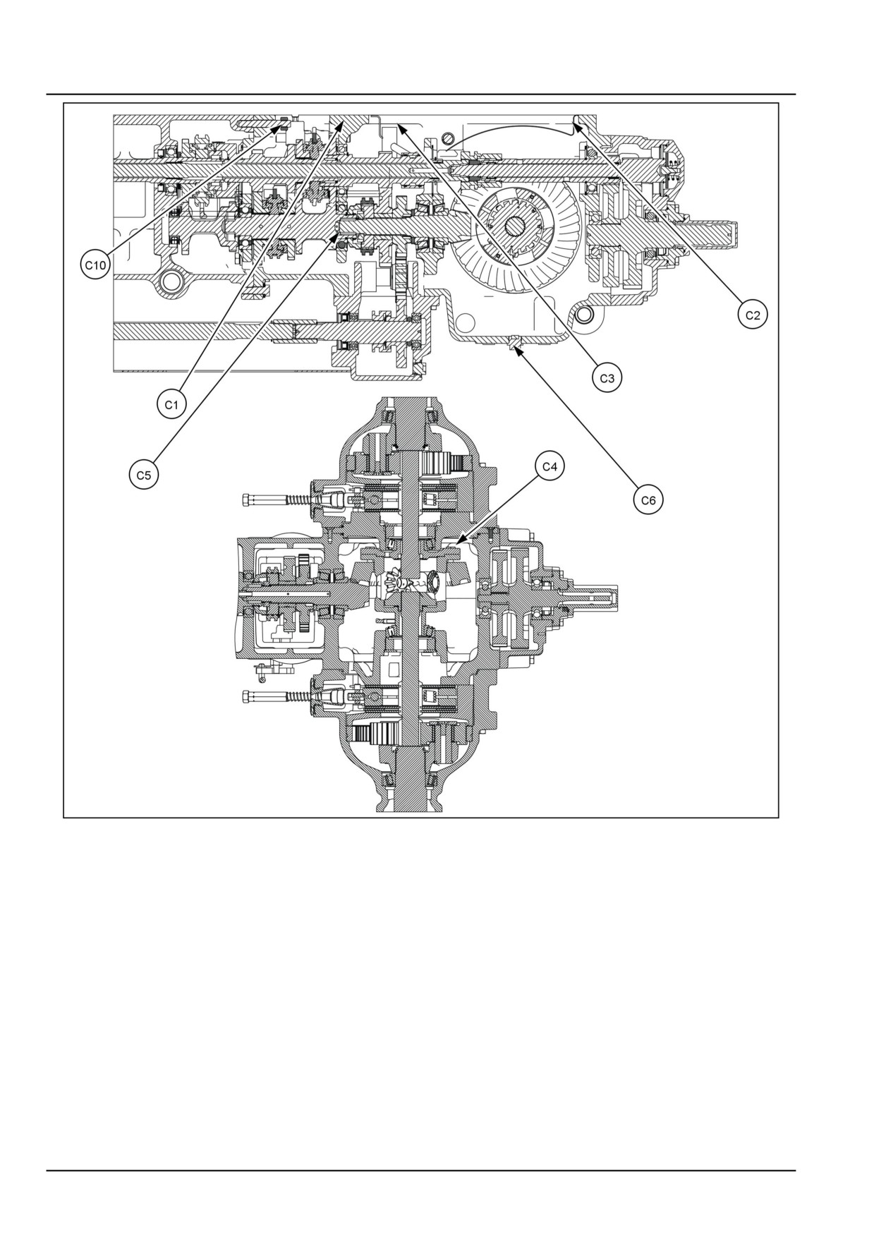
Mechanical transmission - Torque
Description
Thread size
Torque
Gear shift lever cover bolts (C1)
M8
2.5 kgf (5.5 lbf)
Hydraulic housing on transmission retainer bolts (C2)
M10 x 1.25
6.0 kgf (13.2 lbf)
Hydraulic housing on transmission retainer bolts (C3)
M12 x 1.25
10.0 kgf (22.0 lbf)
Crown wheel bolts (C4)
M10
6.0 kgf (13.2 lbf)
Pinion lock nut (C5)
M35
30.0 kgf (66.1 lbf)
Drain plug (C6)
M22
4.5 kgf (9.9 lbf)
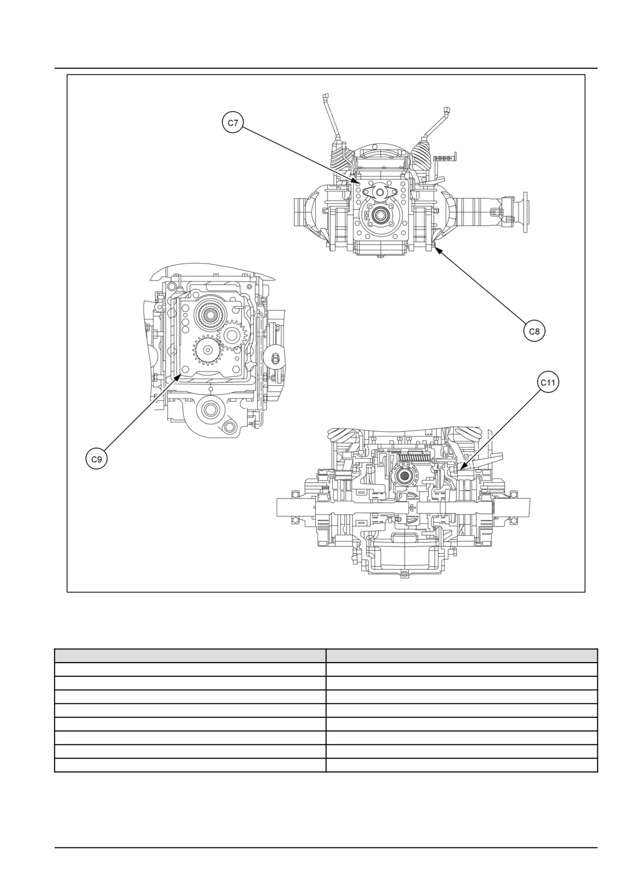
Power Take-Off (PTO) cover bolts (C7)
M12 x 1.25
9.0 kgf (19.8 lbf)
Rear axle to transmission housing attaching bolts (C8)
M12 x 1.25
10.0 kgf (22.0 lbf)
Front cover bolts (C9)
M12 x 1.25
10.0 kgf (22.0 lbf)
Transmission housing to centre housing attaching bolts (C10)
M12 x 1.25
9.0 kgf (19.8 lbf)
Differential lock pedal screw (C11)
M10 x 1.25
6.0 kgf (13.2 lbf)
21.1 [21.114] / 3
Transmission - Mechanical transmission
GNIL14TR00824GA
1
21.1 [21.114] / 4
Transmission - Mechanical transmission
GNIL14TR00828GA
2
Mechanical transmission - Sealing
Description
Sealant specification
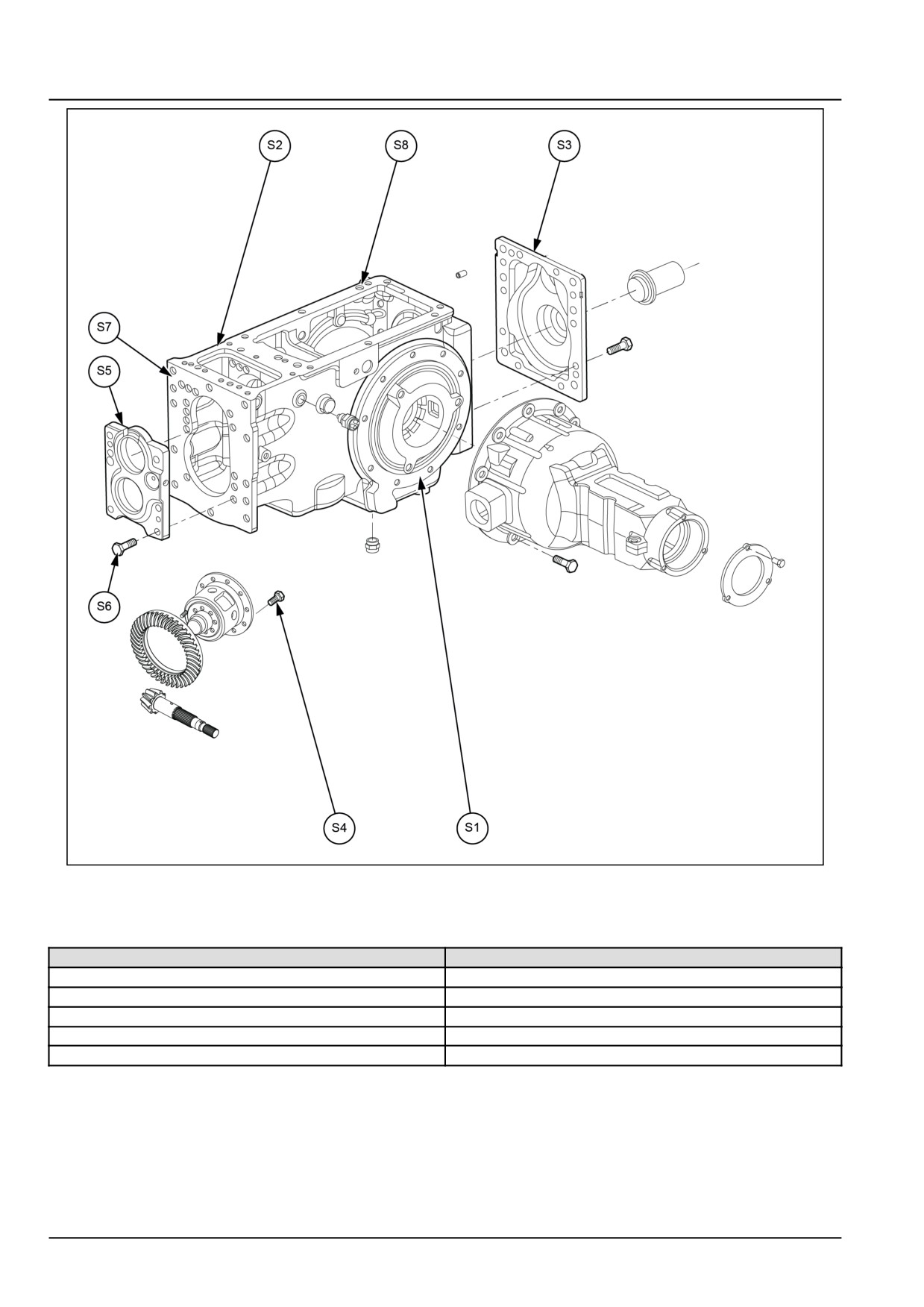
Rear axle to transmission housing (S1)
LOCTITE® 518™
Gear shift lever cover (S2)
LOCTITE® 518™
Power Take-Off (PTO) cover plate (S3)
LOCTITE® 518™
Crown wheel bolts (S4)
LOCTITE® 243™
Front cover plate (S5)
LOCTITE® 518™
Front cover bolts (S6)
LOCTITE® 243™
Transmission to centre housing (S7)
LOCTITE® 518™
Lift housing to transmission housing (S8)
LOCTITE® 518™
21.1 [21.114] / 5
Transmission - Mechanical transmission
GNIL14TR04003GB
1
Mechanical transmission - Special tools
Tool description
Tool number
Socket pinion check nut
84261389
Yoke and spreader
291051 and 291052
Pinion locking tool
380002985
Mandrel with extension
9971381
Special snap ring remover
84261393
21.1 [21.114] / 6
Transmission - Mechanical transmission
Mechanical transmission - Sectional view
GNIL14TR00826FA
1
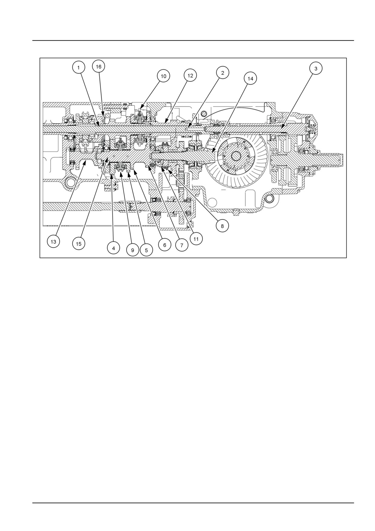
1.
Drive shaft
9.
1st - 2nd Synchrokit
2.
Range shaft
10.
3rd - 4th Synchrokit
3.
Power Take-Off (PTO) input shaft
11.
Hi - Lo gear coupler
4.
1st gear
12.
Low gear on range shaft
5.
2nd gear
13.
Cluster gear
6.
3rd gear
14.
Pinion shaft
7.
4th gear
15.
Driven shaft
8.
Low gear on pinion shaft
16.
Reverse gear
21.1 [21.114] / 7
Transmission - Mechanical transmission
GNIL14TR00827GA
2
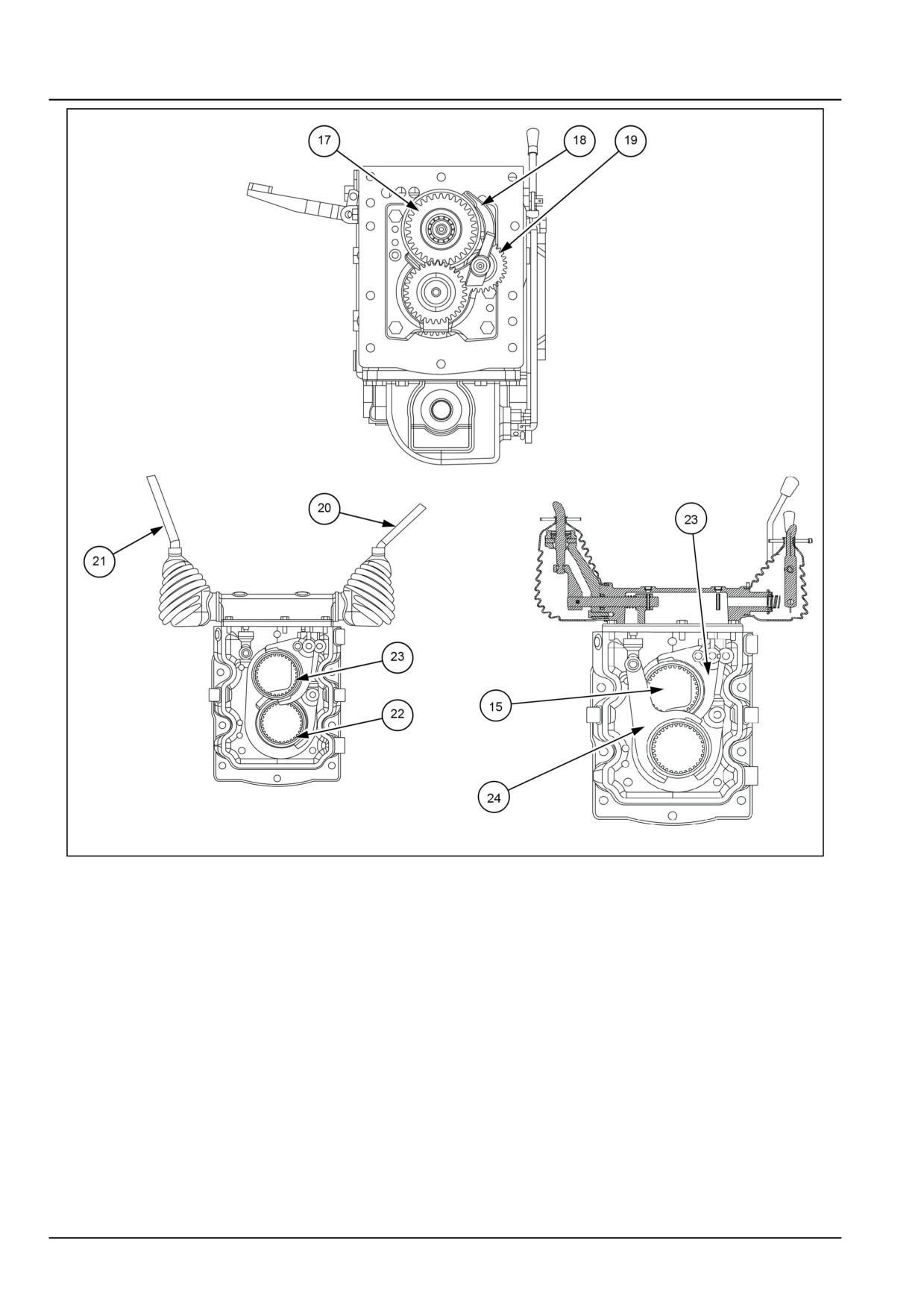
17. Reverse drive gear
21. Range gear shift lever
18. Range gear shift fork
22.
1st - 2nd gear shift fork
19. Reverse intermediate gear
23.
3rd - 4th gear shift fork
20. Hi-Lo gear shift lever
24.
Hi - Lo gear shift fork
21.1 [21.114] / 8
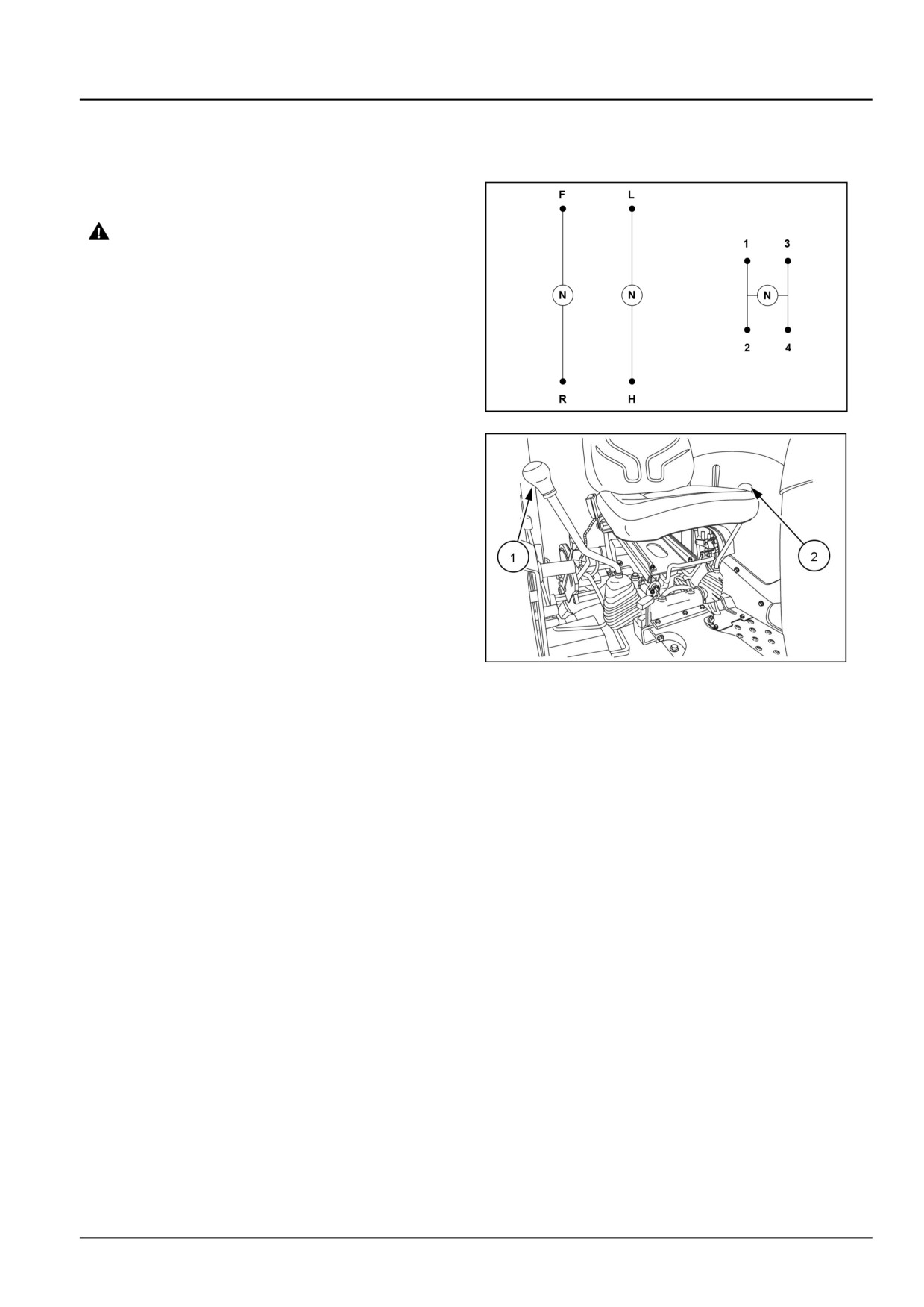
Transmission - Mechanical transmission
Mechanical transmission - Overview
8+8 Synchro shuttle
The transmission has eight forward and eight reverse
gears.
WARNING
Avoid injury! Always do the following before
lubricating, maintaining, or servicing the ma-
chine.
1. Disengage all drives.
2. Engage parking brake.
3. Lower all attachments to the ground, or
raise and engage all safety locks.
4. Shut off engine.
5. Remove key from key switch.
6. Switch off battery key, if installed.
GNIL14TR00513AC
1
7. Wait for all machine movement to stop.
Failure to comply could result in death or se-
rious injury.
W0047A
To select any one of the four forward gears or one reverse
gear use the main gearshift lever (1). To select the high
range or low range, which gives double the number of
available gears use Hi-Low selector lever (2).
To change gear range, depress the clutch pedal. Stop the
tractor and move the Hi-Low selector lever backward (for
high) or forward (for low).
To change the gears in the selected range, depress the
GNIL14TR00785AA
2
clutch pedal and shift main gear lever in the normal way
To select reverse gear (R), first stop the tractor.
NOTE: A safety start switch prevents operation of the
starter motor unless the transmission range lever is in
neutral position (N).
NOTE: If it is necessary to tow the tractor, the Hi-Low
selector and both main gearshift levers must be in neutral.
The transmission has an input shaft called drive shaft (1), range shaft (2), driven shaft (16) and pinion shaft (15).
1st
(4), 2nd (5) gears are integral part of the drive shaft. 3rd (6), 4th (7) gears are integral part of driven shaft. All gears
of input shaft and driven shaft are constant mesh. High gear is assembled in driven shaft while, low gear (8) is fitted
on the pinion shaft. Low drive gear (12) is part of the range shaft and is in constant mesh with low gear on the pinion
shaft.
21.1 [21.114] / 9