New Holland Tractor Workmaster 50 / Workmaster 60 / Workmaster 70 / Tier 4B (final). SERVICE MANUAL - page 2
Index
Engine - 10
Crankshaft and flywheel - 103
Engine flywheel - Inspect
5
Engine flywheel - Remove
3
10.2 [10.103] / 6
Engine - 10
Air cleaners and lines - 202
Workmaster™ 50
Workmaster™ 60
Workmaster™ 70
10.3 [10.202] / 1
Contents
Engine - 10
Air cleaners and lines - 202
SERVICE
Air cleaner
Remove
3
Disassemble
4
Inspect
5
Cleaning
6
Replace
7
Assemble
8
10.3 [10.202] / 2
Engine - Air cleaners and lines
Air cleaner - Remove
NOTE: It is not necessary to remove the complete air
cleaner body, as described below, to service the air cleaner
elements.
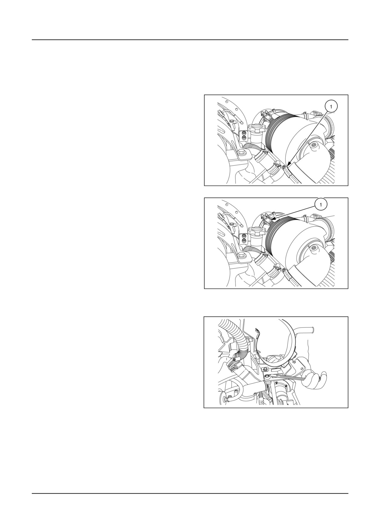
1. Lift the front hood.
2. Loosen the clamp (1) of air cleaner hose. Remove the
air cleaner hose.
GNIL14TR00720AA
1
3. Loosen the bolt of the air cleaner securing clamp. (1).
4. Remove the air cleaner assembly.
GNIL14TR00720AA
2
Air cleaner mounting bracket removal
5. Loosen the bolts and remove the air cleaner mounting
bracket.
GNIL14TR00722AA
3
10.3 [10.202] / 3
Engine - Air cleaners and lines
Air cleaner - Disassemble
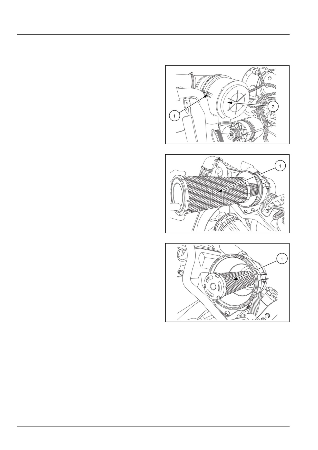
NOTE: The air cleaner assembly can be serviced on the tractor. It is not necessary to remove the complete assembly
from the tractor.
1. Release the locking clips (1) and remove the air cleaner
cover (2).
GNIL14TR00721AA
1
2. Remove the air cleaner outer element (1).
GNIL14TR00723AA
2
3. Remove the inner element (1).
GNIL14TR00724AA
3
10.3 [10.202] / 4
Engine - Air cleaners and lines
Air cleaner - Inspect
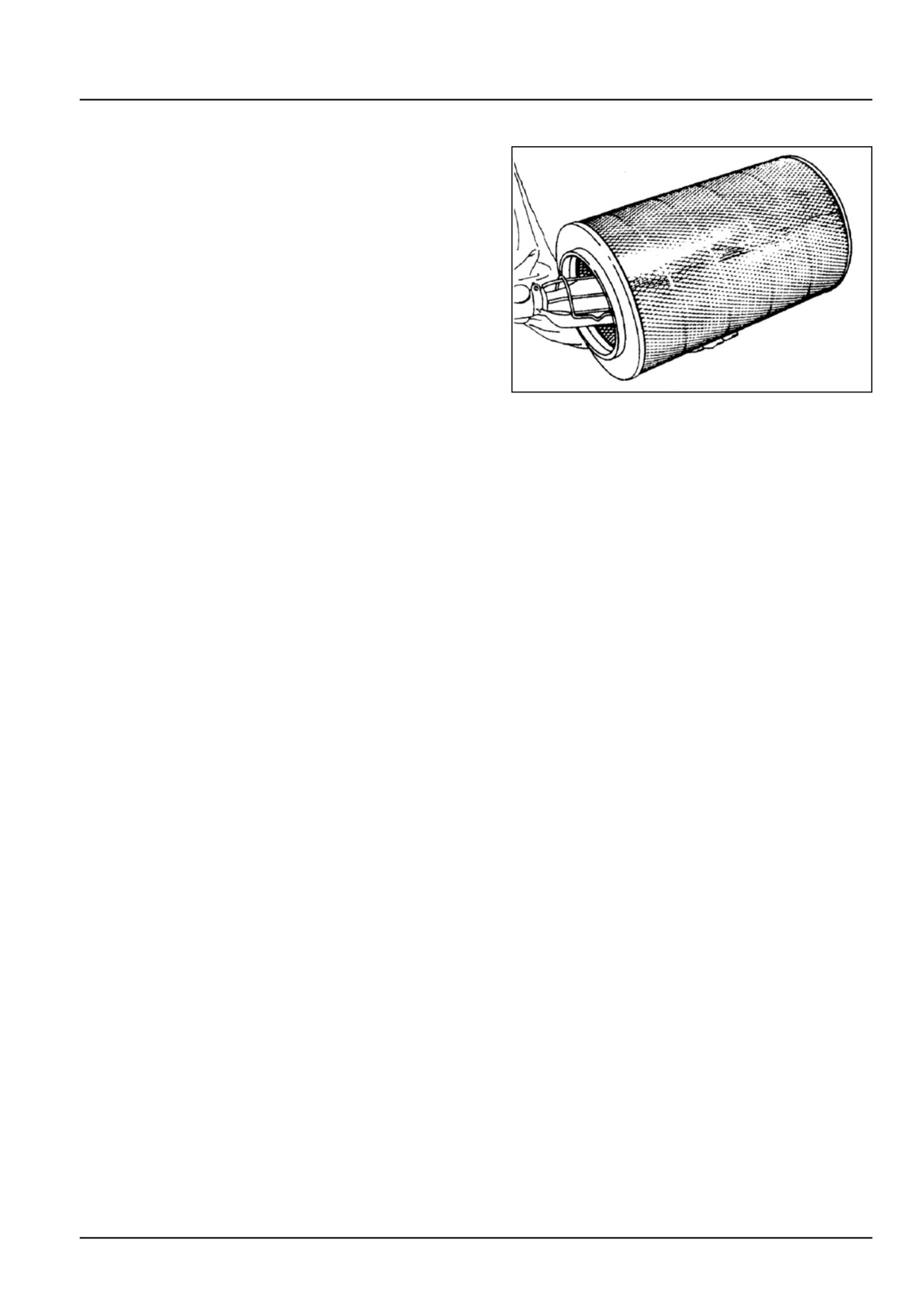
1. Examine the element for damage by placing a light
inside the element.. Discard the element if pin pricks
of light can be seen or there are areas where paper
appears thin.
2. Check the element material for bunching, metal cas-
ing for distortion and rubber gasket for damage. Dis-
card the filter element if damaged.
3. Clean the inside of the air cleaner housing using a
damp, lint free cloth on a probe. Do not damage the
inner filter element. Ensure that the inner end of the
housing is clean and smooth. This ensures good seat-
ing of the rubber seal on the element.
4. Install the cleaned outer element or new outer el-
ement. Gently push it inside the housing in clockwise
direction.
GNIL14TR02103AA
1
5. While fitting back the cover, make sure that the dust
cup/ejector is facing downward.
6. Check all the air intake hoses for damage and re-
place as necessary. Check clamps for tightness.
10.3 [10.202] / 5
Engine - Air cleaners and lines
Air cleaner - Cleaning
WARNING
Chemical hazard!
Stop the fan before you open the lid. Avoid exposure to airborne chemicals. Dust and fumes will be
exhausted if you open the tank lid while the tank is pressurized. Chemicals may cause eye, skin, or
breathing problems. Wear a face mask, gloves, and goggles.
Failure to comply could result in death or serious injury.
W1307A
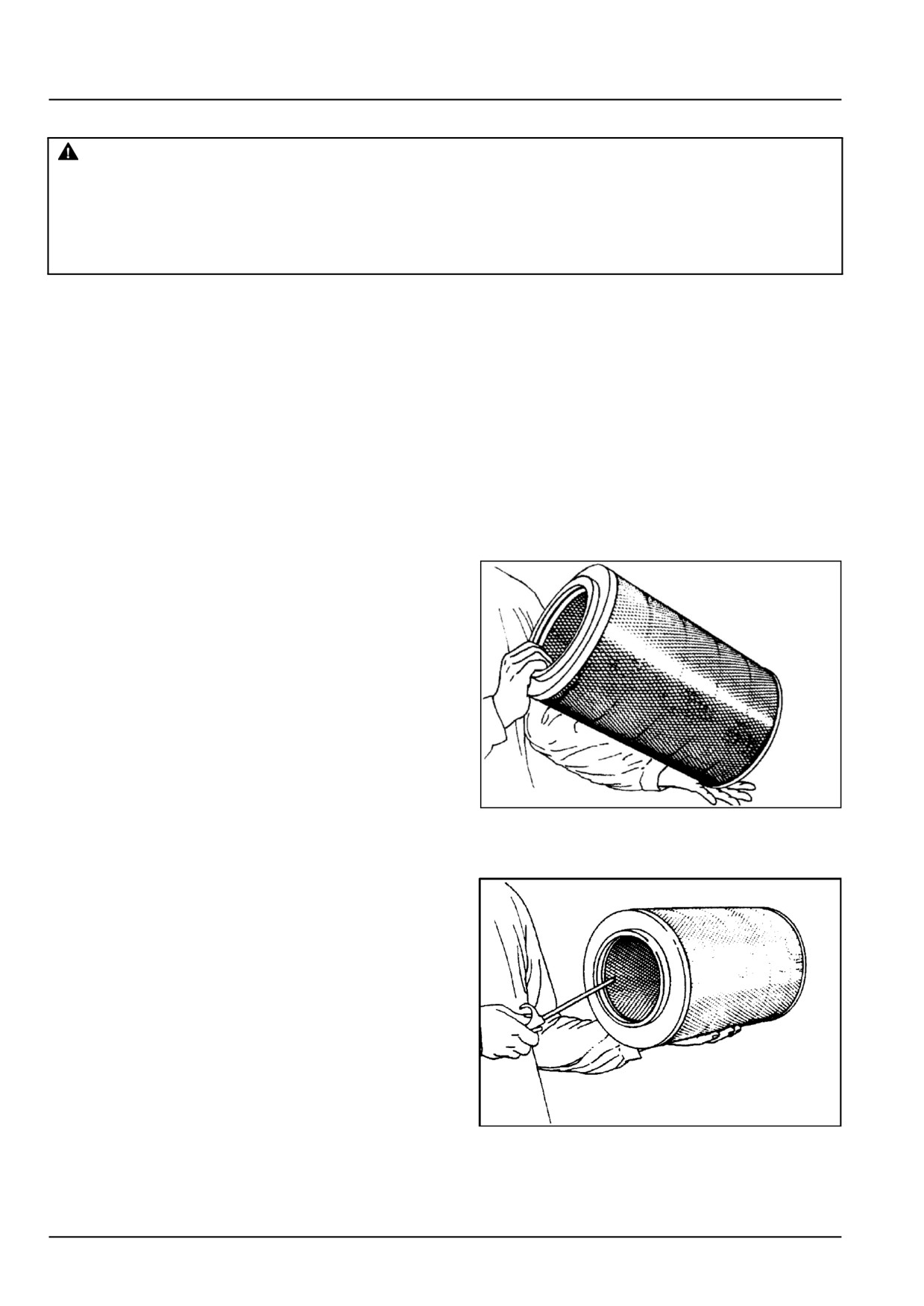
1. Clean the outer element using either method (A) or (B),
depending on the elements condition.
NOTE: An outer element may be dry cleaned (methods A
or B). Every 300 h or when warning bulb glows (whichever
is earlier).
Outer element to be replaced after 3 times of cleaning by
method B or maximum 900 h.
Inner element should be replaced after three outer element
replacements or every 2700 h whichever is earlier.
NOTE: Clean the air filters in a well ventilated room with a provision to artificially throw out the dusty air. If it is not
available, it is advised to do the cleaning outdoors, but never in an unventilated room.
Method A
Lightly tap the element against the palm. Continue till
the accumulated dust comes out completely.
NOTE: Do not tap the element against a hard surface. This
will damage the element.
GNIL14TR02100AA
1
Method B
Using compressed air, not exceeding 1.3 bar, insert the
air nozzle inside the element.
NOTE: Hold the nozzle at a safe distance from the element.
Blow the dust from the inside, through the element, to the
outside.
Never blow air from outside to inside.
GNIL14TR02101AA
2
10.3 [10.202] / 6
Engine - Air cleaners and lines
Air cleaner - Replace
1. The inner element to be removed only at the time of
replacement. It should never be cleaned. The inner
element should be replaced after three outer element
replacements or 2700 h whichever is earlier.
2. Follow the similar instructions of removing and fitting
outer element from casting to replace inner element.
10.3 [10.202] / 7
Engine - Air cleaners and lines
Air cleaner - Assemble
Fitment
For assembly, follow the reverse order of disassembly.
Clean the interior of the air filter housing using a clean
cloth.
10.3 [10.202] / 8
Index
Engine - 10
Air cleaners and lines - 202
Air cleaner - Assemble
8
Air cleaner - Cleaning
6
Air cleaner - Disassemble
4
Air cleaner - Inspect
5
Air cleaner - Remove
3
Air cleaner - Replace
7
10.3 [10.202] / 9
Engine - 10
Fuel filters - 206
Workmaster™ 50
Workmaster™ 60
Workmaster™ 70
10.4 [10.206] / 1
Contents
Engine - 10
Fuel filters - 206
SERVICE
Pre-filter
Remove
3
Install
4
10.4 [10.206] / 2
Engine - Fuel filters
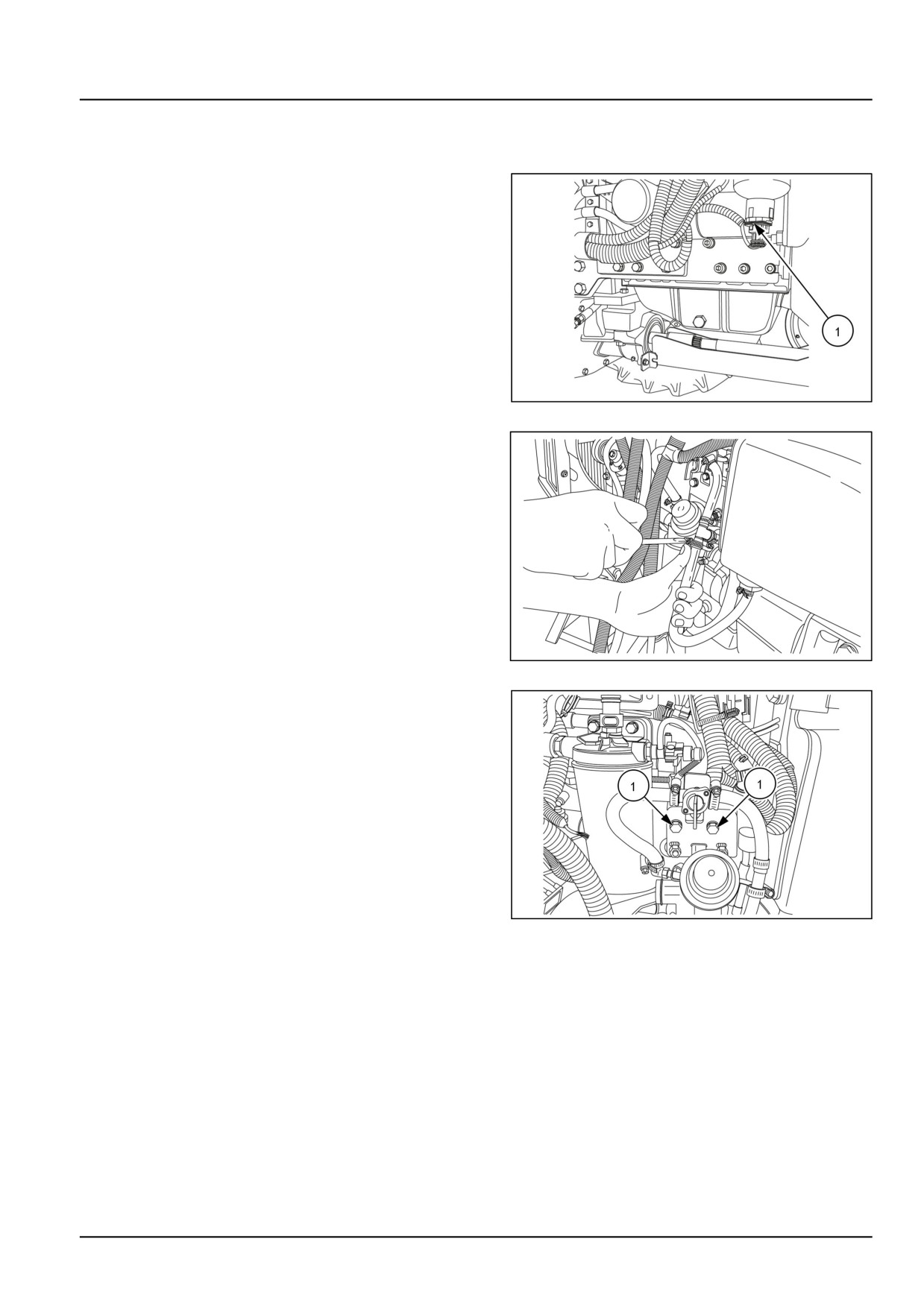
Pre-filter - Remove
1. Lift the front hood.
2. Remove the electrical connections on the fuel prefilter.
GNIL14TR00737AA
1
3. Disconnect all the fuel lines on the fuel prefilter.
GNIL14TR00712AA
2
4. Loosen the bolts (1) and remove the fuel prefilter.
GNIL14TR00862AA
3
10.4 [10.206] / 3
Engine - Fuel filters
Pre-filter - Install
For installation, follow the reverse order of removal.
10.4 [10.206] / 4
Index
Engine - 10
Fuel filters - 206
Pre-filter - Install
4
Pre-filter - Remove
3
10.4 [10.206] / 5
Engine - 10
Fuel tanks - 216
Workmaster™ 50
Workmaster™ 60
Workmaster™ 70
10.5 [10.216] / 1
Contents
Engine - 10
Fuel tanks - 216
SERVICE
Fuel cooler
Remove
3
Install
4
10.5 [10.216] / 2
Engine - Fuel tanks
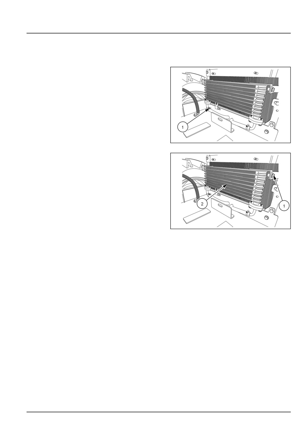
Fuel cooler - Remove
1. Lift the front hood.
2. Remove the battery. See Battery - Remove (55.302).
3. Disconnect the fuel pipes (1) on the fuel cooler.
GNIL14TR00703AA
1
4.
1. Loosen all the bolts (1).
2. Remove the fuel cooler (2).
GNIL14TR00703AA
2
10.5 [10.216] / 3
Engine - Fuel tanks
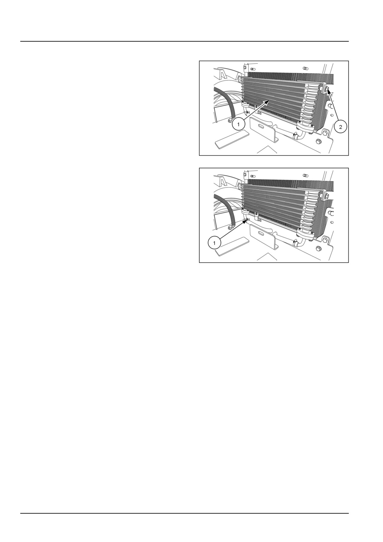
Fuel cooler - Install
1. Install the fuel cooler (1) and tighten the bolts (2).
GNIL14TR00703AA
1
2. Connect the fuel pipes (1) on the fuel cooler.
GNIL14TR00703AA
2
3. Install the battery. See Battery - Install (55.302).
10.5 [10.216] / 4
Index
Engine - 10
Fuel tanks - 216
Fuel cooler - Install
4
Fuel cooler - Remove
3
10.5 [10.216] / 5
10.5 [10.216] / 6
Engine - 10
Aftercooler - 310
Workmaster™ 50
Workmaster™ 60
Workmaster™ 70
10.6 [10.310] / 1
Contents
Engine - 10
Aftercooler - 310
SERVICE
Aftercooler
Remove
3
Install
5
10.6 [10.310] / 2
Engine - Aftercooler
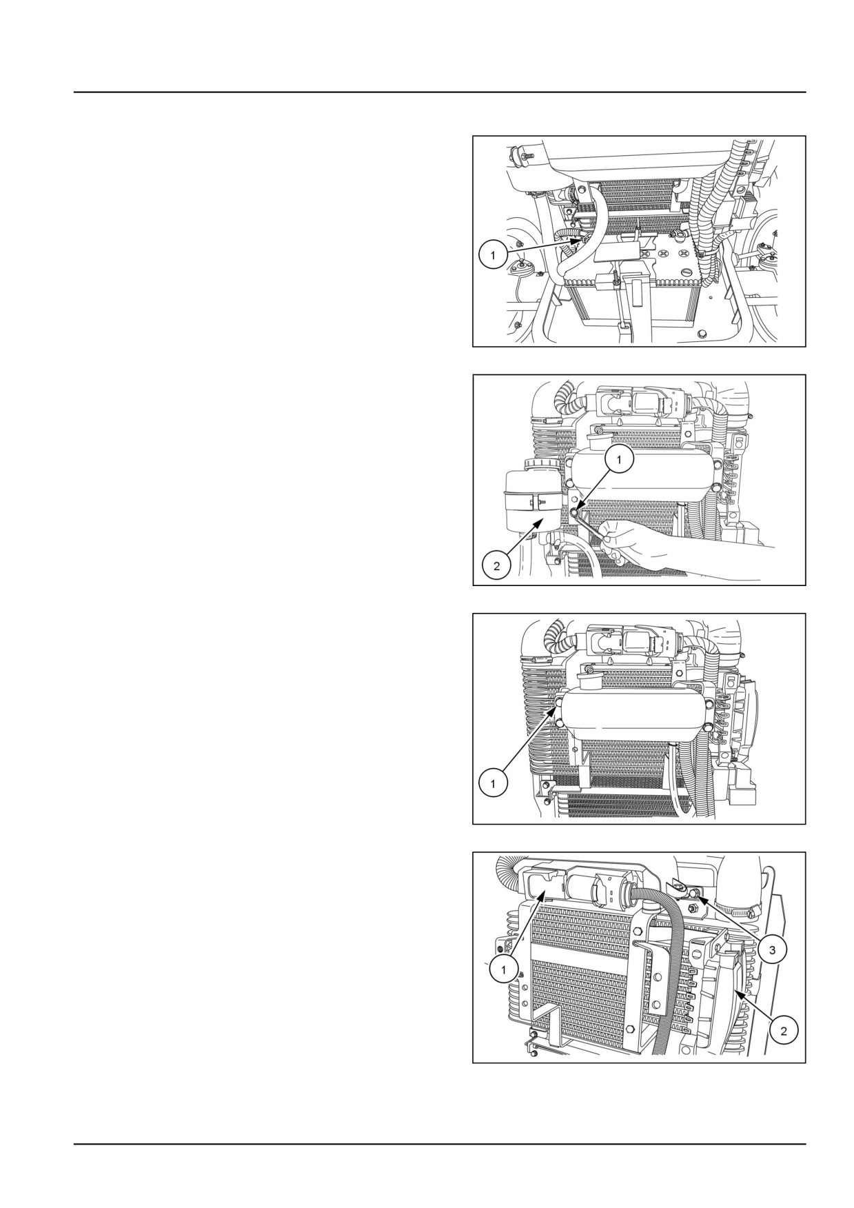
Aftercooler - Remove
1.
1. Lift the front hood.
2. Disconnect the negative terminal (1) of the battery.
GNIL14TR00784AA
1
2.
1. Loosen the bolt (1).
2. Remove the steering oil reservoir (2).
GNIL14TR00759AA
2
3.
1. Disconnect the hose from the radiator coolant reser-
voir.
2. Loosen the bolts (1) and remove the coolant reser-
voir.
GNIL14TR00757AA
3
4.
1. Remove the electrical couplers on the Engine Con-
trol Unit (ECU) bracket (1) and the fuse box (2).
2. Loosen the bolts (3) and remove the ECU bracket.
GNIL14TR00762AA
4
10.6 [10.310] / 3
Engine - Aftercooler
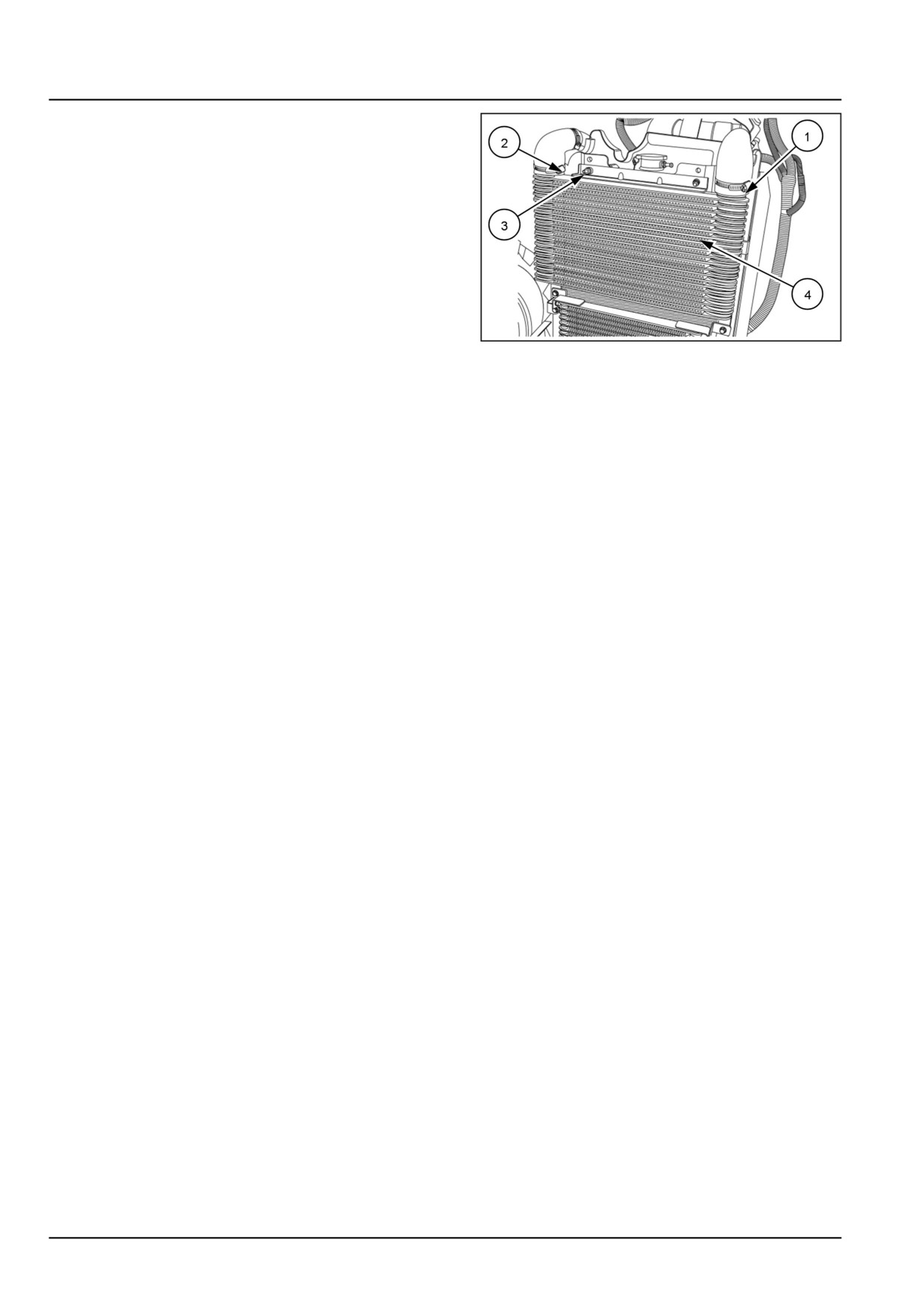
5.
1. Remove the inlet (1) and the outlet hoses (2) of the
after cooler.
2. Loosen and remove the mounting bolts (3) and re-
move the after cooler (4).
GNIL14TR00702AA
5
10.6 [10.310] / 4
Engine - Aftercooler
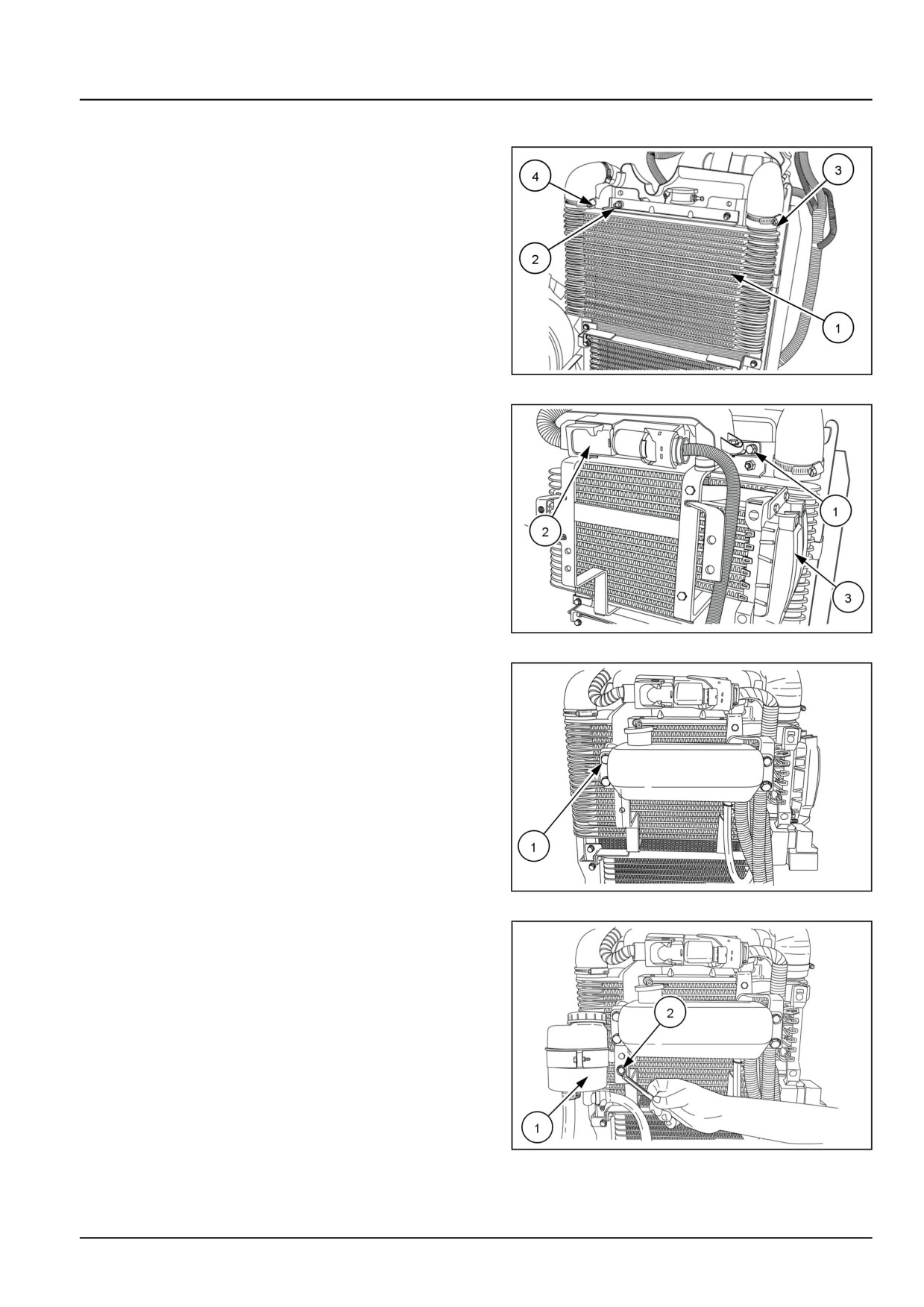
Aftercooler - Install
1.
1. Install the after cooler (1) on the mounting bracket
and tighten the bolts (2).
2. Connect the inlet hose (3) and outlet hose (4) of the
radiator.
GNIL14TR00702AA
1
2.
1. Install the Engine Control Unit (ECU) and tighten the
bolts (1).
2. Connect the electrical couplers on the ECU (1) and
fuse box.
GNIL14TR00762AA
2
3.
1. Install the radiator coolant reservoir and tighten the
bolts (1).
2. Connect the hoses to the radiator coolant reservoir.
GNIL14TR00757AA
3
4. Install the steering oil reservoir (1) and tighten the bolt
(2).
GNIL14TR00759AA
4
10.6 [10.310] / 5
Engine - Aftercooler
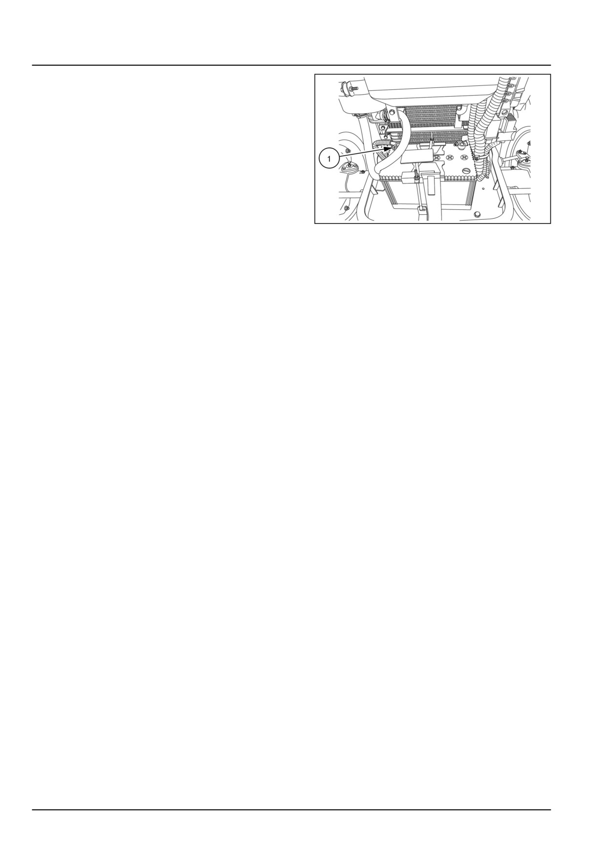
5. Connect the negative terminal (1) of the battery.
GNIL14TR00784AA
5
10.6 [10.310] / 6
Index
Engine - 10
Aftercooler - 310
Aftercooler - Install
5
Aftercooler - Remove
3
10.6 [10.310] / 7
Engine - 10
Engine cooling system - 400
Workmaster™ 50
Workmaster™ 60
Workmaster™ 70
10.7 [10.400] / 1
Contents
Engine - 10
Engine cooling system - 400
SERVICE
Radiator
Remove
3
Install
5
10.7 [10.400] / 2
Engine - Engine cooling system
Radiator - Remove
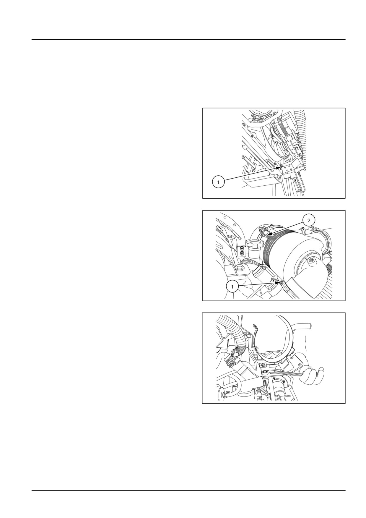
1. Lift the front hood.
2. Disconnect the wiring couplers on the ECU (Engine
Control Unit) bracket and fuse box. Remove the ECU
Bracket, steering oil reservoir, intercooler and fuel
cooler. See Aftercooler - Remove (10.310) and Fuel
cooler - Remove (10.216).
3. Remove the cock (1) and drain the coolant from the
radiator.
NOTE: Remove the radiator cap to assist draining.
GNIL14TR00760AA
1
4. Loosen the clamp (1) on the air inlet hose. Remove the
bolts securing the air cleaner (2) to the radiator.
GNIL14TR00720AA
2
5. Loosen the bolts and remove the air cleaner mounting
bracket.
GNIL14TR00860AA
3
10.7 [10.400] / 3
Engine - Engine cooling system
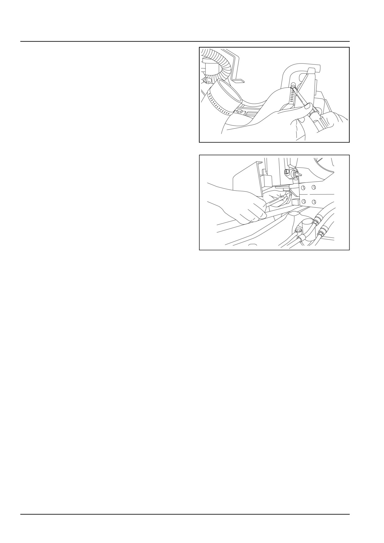
6. Remove all the hoses from the radiator
GNIL14TR00717AA
4
7. Loosen and remove all the radiator mounting bolts. Re-
move the radiator from the tractor.
GNIL14TR00761AA
5
10.7 [10.400] / 4
Engine - Engine cooling system
Radiator - Install
For installation, follow the reverse order of removal.
10.7 [10.400] / 5
Index
Engine - 10
Engine cooling system - 400
Radiator - Install
5
Radiator - Remove
3
10.7 [10.400] / 6
CNH Industrial America New Holland Site 100 Brubaker Avenue New Holland, Pennsylvania United States
17557
SERVICE - Technical Publications & Tools
PRINTED IN U.S.A.
All rights reserved. No part of the text or illustrations of this publication may be reproduced.
NEW HOLLAND policy is one of continuous improvement and the right to change prices, specification or equipment
at any time without notices is reserved.
All data given in this publication is subject to production variations. Dimensions and weight are approximate only and
the illustrations do not necessarily show products in standard condition. For exact information about any particular
product, please consult your NEW HOLLAND Dealer.
EN
SERVICE MANUAL
Clutch
Workmaster™ 50
Workmaster™ 60
Workmaster™ 70
18
Contents
Clutch - 18
[18.100] Clutch mechanical release control
18.1
[18.110] Clutch and components
18.2
18
Clutch - 18
Clutch mechanical release control - 100
Workmaster™ 50
Workmaster™ 60
Workmaster™ 70
18.1 [18.100] / 1
Contents
Clutch - 18
Clutch mechanical release control - 100
SERVICE
Clutch mechanical release control
Remove
3
Install
7
Adjust
8
18.1 [18.100] / 2
Clutch - Clutch mechanical release control
Clutch mechanical release control - Remove
CAUTION
Avoid injury!
Handle all parts carefully. Do not place your hands or fingers between parts. Use Personal Protec-
tive Equipment (PPE) as indicated in this manual, including protective goggles, gloves, and safety
footwear.
Failure to comply could result in minor or moderate injury.
C0145A
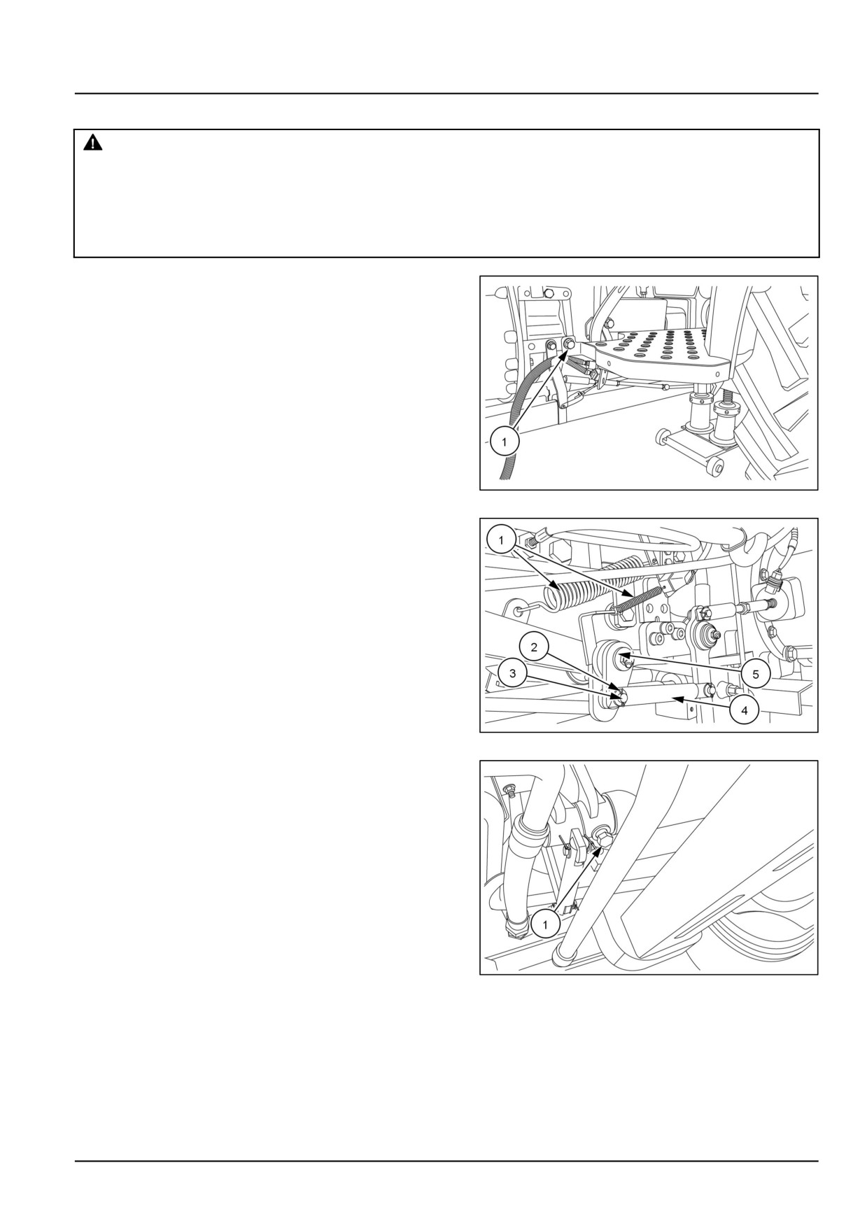
1. Remove all foot platform bolts, and remove the
left-hand side footboard. See Protections and foot-
boards - Remove (90.118).
GNIL14TR00767AA
1
2. Remove clutch pedal spring (1).
3. Remove the split pin (2)
4. Remove the roll pin (3).
5. Disconnect the linkage (4).
6. Remove the circlip (5).
GNIL14TR00766AA
2
7. Loosen the lock screw (1).
GNIL14TR00812AA
3
18.1 [18.100] / 3