New Holland Tractor Workmaster 50 / Workmaster 60 / Workmaster 70 / Tier 4B (final). SERVICE MANUAL - page 1
SERVICE MANUAL
Workmaster™ 50 / Workmaster™ 60 /
Workmaster™ 70
Tier 4B (final)
Tractor
Part number 47866583
1st edition English
December 2015
SERVICE MANUAL
Workmaster™ 50
Workmaster™ 60
Workmaster™ 70
EN
Link Product / Engine
Product
Market Product
Engine
Workmaster™ 50 Compact tractor,
North America
R 753 IE4
2WD, 50 HP, TIER 4B (FINAL)
Workmaster™ 50 Compact tractor,
North America
R 753 IE4
4WD, 50 HP, TIER 4B (FINAL)
Workmaster™ 60 Compact tractor,
North America
R 753 IE4
2WD, 60 HP, TIER4B (FINAL)
Workmaster™ 60 Compact tractor,
North America
R 753 IE4
4WD, 60 HP, TIER 4B (FINAL)
Workmaster™ 70 Compact tractor,
North America
R 753 IE4
2WD, TIER 4B (FINAL)
Workmaster™ 70 Compact tractor,
North America
R 753 IE4
4WD, 70 HP, TIER 4B (FINAL)
Contents
INTRODUCTION
Engine
10
[10.001] Engine and crankcase
10.1
[10.103] Crankshaft and flywheel
10.2
[10.202] Air cleaners and lines
10.3
[10.206] Fuel filters
10.4
[10.216] Fuel tanks
10.5
[10.310] Aftercooler
10.6
[10.400] Engine cooling system
10.7
Clutch
18
[18.100] Clutch mechanical release control
18.1
[18.110] Clutch and components
18.2
Transmission
21
[21.114] Mechanical transmission
21.1
[21.130] Mechanical transmission external controls
21.2
[21.140] Mechanical transmission internal components
21.3
[21.145] Gearbox internal components
21.4
[21.200] Dropbox
21.5
Four-Wheel Drive (4WD) system
23
[23.314] Drive shaft
23.1
Front axle system
25
[25.100] Powered front axle
25.1
[25.102] Front bevel gear set and differential
25.2
[25.108] Final drive hub, steering knuckles, and shafts
25.3
[25.310] Final drives
25.4
[25.400] Non-powered front axle
25.5
Rear axle system
27
[27.100] Powered rear axle
27.1
[27.106] Rear bevel gear set and differential
27.2
[27.120] Planetary and final drives
27.3
Power Take-Off (PTO)
31
[31.101] Rear mechanical control
31.1
[31.110] One-speed rear Power Take-Off (PTO)
31.2
[31.114] Two-speed rear Power Take-Off (PTO)
31.3
Brakes and controls
33
[33.120] Mechanical service brakes
33.1
Hydraulic systems
35
[35.000] Hydraulic systems
35.1
[35.100] Main lift system
35.2
[35.104] Fixed displacement pump
35.3
[35.204] Remote control valves
35.4
[35.300] Reservoir, cooler, and filters
35.5
[35.355] Hydraulic hand control
35.6
[35.359] Main control valve
35.7
Steering
41
[41.101] Steering control
41.1
[41.200] Hydraulic control components
41.2
[41.206] Pump
41.3
[41.216] Cylinders
41.4
Wheels
44
[44.511] Front wheels
44.1
[44.520] Rear wheels
44.2
Electrical systems
55
[55.000] Electrical system
55.1
[55.024] Transmission control system
55.2
[55.048] Rear Power Take-Off (PTO) control system
55.3
[55.100] Harnesses and connectors
55.4
[55.201] Engine starting system
55.5
[55.301] Alternator
55.6
[55.302] Battery
55.7
[55.404] External lighting
55.8
[55.405] External lighting switches and relays
55.9
[55.408] Warning indicators, alarms, and instruments
55.10
[55.512] Cab controls
55.11
[55.DTC] FAULT CODES
55.12
Platform, cab, bodywork, and decals
90
[90.100] Engine hood and panels
90.1
[90.110] Operator platform less cab
90.2
[90.116] Fenders and guards
90.3
[90.118] Protections and footboards
90.4
Contents
INTRODUCTION
Foreword
3
Foreword Ecology and the environment
4
Advice
5
International symbols
6
Safety rules
7
Basic instructions hardware
11
General specification - Biodiesel Fuels
12
2
INTRODUCTION
Foreword
This repair manual provides the technical information needed to properly service the model tractors. Use this manual
in conjunction with the operator's manual for complete operation, adjustment, and maintenance information
On NEW HOLLAND equipment, left and right are determined by standing behind the unit, looking in the direction of
travel.
3
INTRODUCTION
Foreword Ecology and the environment
Soil, air, and water are vital factors of agriculture and life in general. When legislation does not yet rule the treatment
of some of the substances which are required by advanced technology, common sense should govern the use and
disposal of products of a chemical and petrochemical nature.
NOTICE: The following are recommendations which may be of assistance:
• Become acquainted with and ensure that you understand the relative legislation applicable to your country.
• Where no legislation exists, obtain information from suppliers of oils, filters, batteries, fuels, antifreeze, cleaning
agents, etc., with regard to their effect on man and nature and how to safely store, use and dispose of these sub-
stances.
• Agricultural consultants will, in many cases, be able to help you as well.
Helpful hints
• Avoid filling tanks using cans or inappropriate pressurized fuel delivery systems which may cause considerable
spillage.
• In general, avoid skin contact with all fuels, oils, acids, solvents, etc. Most of them contain substances which may
be harmful to your health.
• Modern oils contain additives. Do not burn contaminated fuels and or waste oils in ordinary heating systems.
• Avoid spillage when draining off used engine coolant mixtures, engine, gearbox and hydraulic oils, brake fluids, etc.
Do not mix drained brake fluids or fuels with lubricants. Store them safely until they can be disposed of in a proper
way to comply with local legislation and available resources.
• Modern coolant mixtures, i.e. antifreeze and other additives, should be replaced every two years. They should not
be allowed to get into the soil but should be collected and disposed of properly.
• Do not open the air-conditioning system yourself. It contains gases which should not be released into the atmos-
phere. Your NEW HOLLAND dealer or air conditioning specialist has a special extractor for this purpose and will
have to recharge the system properly.
• Repair any leaks or defects in the engine cooling or hydraulic system immediately.
• Do not increase the pressure in a pressurized circuit as this may lead to a component failure.
• Protect hoses during welding as penetrating weld splatter may burn a hole or weaken them, allowing the loss of
oils, coolant, etc.
4
INTRODUCTION
International symbols
As a guide to the operation of the machine, various universal symbols have been utilized on the instruments, controls,
switches, and fuse box. The symbols are shown below with an indication of their meaning.
Thermostart
Position
Radio
PTO
starting aid
Control
Alternator
Keep alive
Transmission
Draft
charge
memory
in neutral
Control
Creeper
Accessory
Fuel level
Turn signals
gears
socket
Automatic
Turn signals
Slow or
Implement
Fuel shut-off
-one trailer
low setting
socket
Engine speed
Turn signals
Fast or high
%age
(rev/min x 100)
-two trailers
setting
slip
Front wind-
Ground
Hitch raise
Hours recorded
screen
speed
(rear)
wash/wipe
Rear wind-
Engine oil
Differential
Hitch lower
screen
pressure
lock
(rear)
wash/wipe
Rear axle
Engine coolant
Heater temp-
Hitch height
oil tem-
temperature
erature control
limit (rear)
perature
Coolant
Transmission
Hitch height
Heater fan
level
oil pressure
limit (front)
FWD
Hitch dis-
Tractor lights
Air conditioner
engaged
abled
Hydraulic and
Headlamp
Air filter
FWD dis-
transmission
main beam
blocked
engaged
filters
Headlamp
Parking
Remote
Warning!
dipped beam
brake
valve extend
Brake fluid
Hazard
Remote
Work lamps
level
warning lights
valve retract
Stop
Trailer
Variable
Remote
lamps
brake
control
valve float
Malfunction!
Roof
Pressurised!
Horn
See Operator's
beacon
Open carefully
Manual
Warning !
Malfunction!
Corrosive
(alter-
substance
native symbol)
6
INTRODUCTION
Safety rules
PRECAUTIONARY STATEMENTS
Personal Safety
Throughout this manual and on machine signs, you will find precautionary statements ("DANGER", "WARNING", and
"CAUTION") followed by specific instructions. These precautions are intended for the personal safety of you and
those working with you. Please take the time to read them.
Machine Safety
The precautionary statement ("IMPORTANT") is followed by specific instructions. This statement is intended for ma-
chine safety.
NOTICE: The word "IMPORTANT" is used to inform the reader of something they need to know to prevent minor
machine damage if a certain procedure is not followed.
Information
NOTE: Instructions used to identify and present supplementary information.
Legal obligations
This machine may be equipped with special guarding or other devices in compliance with local legislation. Some of
these require active use by the operator. Therefore, check local legislation on the usage of this machine.
Accident prevention
Most accidents or injuries that occur in workshops are the result of a non compliance to simple and fundamental safety
regulations. In most case, accidents can be avoided by foreseeing possible causes and consequently acting with the
necessary caution and care.
Accidents may occur with all types of machines, regardless of how well the machine in question was designed and
built.
A careful and informed service technician is the best guarantee against accidents.
Decisive awareness of the most basic safety rule is normally sufficient to avoid many serious accident.
Safety requirements for fluid power systems and components - Hydraulics (European stan-
dard PR EM 982)
WARNING
Avoid injury!
Before you start any work on the unit:
• Park the unit on a hard, level surface.
• Apply the parking brake.
• Completely lower the attachments.
• Relieve all the hydraulic system pressure.
• Shut down the engine.
• Remove the ignition key.
• Secure the unit with wheel chocks.
• Turn the battery isolator switch to the OFF position.
Failure to comply could result in death or serious injury.
W1371A
Flexible hose assemblies must not be constructed from hoses which have been previously used as part of a hose
assembly.
Do not weld hydraulic piping.
When flexible hoses or piping are damaged, replace them immediately.
It is forbidden to modify a hydraulic accumulator by machining, welding or any other means.
7
INTRODUCTION
Before removing hydraulic accumulators for servicing, the liquid pressure in the accumulators must be reduced to
zero.
Pressure check on hydraulic accumulators shall be carried out by method recommended by the accumulator manu-
facturer.
Care must be taken not to exceed the maximum allowable pressure of the accumulator. After any check or adjustment
there must be no leakage of gas.
Safety rules
A careful operator is the best operator. Most accidents
can be avoided by observing certain precautions. To
help prevent accidents, read and take the following
precautions before operating this tractor. Equipment
should be operated only by those who are responsible
and instructed to do so.
The tractor
1. Read the Operator's Manual carefully before using the tractor. Lack of operating knowledge can lead to accidents.
2. Use an approved roll bar and seat belt for safe operation. Overturning a tractor without a roll bar can result in
death or injury. If your tractor is not equipped with a roll bar and seat belt, see your NEW HOLLAND Dealer.
3. Always use the seat belt. The only instance when the seat belt should not be used is if the roll bar has been
removed from the tractor or folding ROPS is in down position.
4. If a front end loader is to be installed, always use a FOPS (Falling Object Protective Structure) canopy to avoid
injury from falling objects.
5. Use the handrails and step plates when getting on and off the tractor to prevent falls. Keep steps and platform
cleared of mud and debris.
6. Do not permit anyone but the operator to ride on the tractor. There is no safe place for extra riders.
7. Keep all safety decals clean of dirt and grime, and replace all missing, illegible, or damaged safety decals. See
the list of decals in the Decal section of this manual.
Servicing the tractor
1.
The cooling system operates under pressure which is controlled by the radiator cap. It is dangerous to remove
the cap while the system is hot. Always turn the cap slowly to the first stop and allow pressure to escape before
removing the cap entirely.
2.
Keep any type of open flame away from the tractor and do not smoke while refuelling. Wait for the engine to cool
before refueling.
3.
Keep the tractor and equipment, particularly brakes and steering, maintained in a reliable and satisfactory con-
dition to ensure your safety and comply with legal requirements.
4.
Keep open flame or cold weather starting aids away from the battery to prevent fires or explosions. Use jumper
cables according to instructions to prevent sparks which could cause explosion.
5.
Stop the engine before performing any service on the tractor.
6.
Escaping hydraulic/diesel fluid under pressure can penetrate the skin causing serious injury. If fluid is injected
into the skin, obtain medical attention immediately or gangrene may result.
• Do not use your hand to check for leaks.
• Use a piece of cardboard or paper to search for leaks.
• Stop the engine and relieve pressure before connecting or disconnecting lines.
• Tighten all connections before starting the engine or pressurizing lines.
7.
Do not modify or permit anyone else to modify or alter this tractor or any of its components or functions without
first consulting a NEW HOLLAND Dealer.
8.
The fuel oil in the injection system is under high pressure and can penetrate the skin. Unqualified persons should
not remove or attempt to adjust a pump, injector, nozzle, or any other part of the fuel injection system. Failure to
follow these instructions can result in serious injury.
9.
Continuous long-term contact with used engine oil may cause skin cancer. Avoid prolonged contact with used
engine oil. Wash skin promptly with soap and water.
8
INTRODUCTION
10. Some components of your tractor, such as gaskets and friction surfaces (brake linings, clutch linings, etc.)
may contain asbestos. Breathing asbestos dust is dangerous to your health. You are advised to have any
maintenance or repair on such components carried out by an authorized NEW HOLLAND Dealer. However,
if service operations are to be undertaken on parts that contain asbestos, the essential precautions listed
below must be observed:
• Work out of doors or in a well ventilated area.
• Dust found on the tractor or produced during work on the tractor should be removed by extraction, not by
blowing.
• Dust waste should be dampened, placed in a sealed container, and marked to ensure safe disposal.
• If any cutting, drilling, etc. is attempted on materials containing asbestos, the item should be dampened and
only hand tools or low speed power tools used.
Operating the tractor
1.
Before starting the tractor, apply the parking brake, place the PTO lever in the 'OFF' position, the lift control lever
in the down position, the remote control valve levers in the neutral position, and the transmission in neutral.
2.
Always sit in the tractor seat when starting the engine or operating controls. Do not start the engine or operate
controls while standing beside the tractor.
3.
Do not bypass the neutral start switches. Consult your NEW HOLLAND Dealer if your neutral start controls
malfunction. Use jumper cables only in the recommended manner. Improper use can result in tractor runaway.
4.
Avoid accidental contact with the gear shift lever while the engine is running, as this can cause unexpected tractor
movement.
5.
Before getting off the tractor, disengage the PTO, turn the engine off, and apply the parking brake. Never get off
the tractor while it is in motion.
6.
Do not park the tractor on a steep incline.
7.
Do not operate the tractor engine in an enclosed building without adequate ventilation. Exhaust fumes can cause
death or illness.
8.
If the power steering or engine ceases operating, stop the tractor immediately.
9.
Pull only from the drawbar or the lower link drawbar in the down position. Use only a drawbar pin that locks in
place. Pulling from the tractor rear axle or any point above the axle may cause the tractor to upset.
10.
If the front end of the tractor tends to rise when heavy implements are attached to the three-point hitch, install
front end or front wheel weights. Do not operate the tractor with a light front end.
11.
Always set the hydraulic selector lever in position control when attaching or transporting equipment. Ensure
hydraulic couplers are properly mounted and will disconnect safely in case of accidental detachment of implement
12.
Do not leave equipment in the raised position.
13.
Use the flasher/turn signal lights and Slow Moving Vehicle (SMV) signs when traveling on public roads both day
and night (unless prohibited by law).
14.
When operating at night, adjust lights to prevent blinding oncoming drivers.
Driving the tractor
1. Watch where you are going, especially at row ends, on roads, around trees and low hanging obstacles.
2. To avoid upsets, drive the tractor with care and at a safe speed. Use extra caution when operating over rough
ground, when crossing ditches or slopes, and when turning corners.
3. To provide two-wheel braking, lock tractor brake pedals together when transporting on roads.
4. Do not coast or free wheel down hills. Use the same gear when going downhill as is used when going uphill.
5. Any towed vehicle with a total weight exceeding that of the towing tractor should be equipped with brakes for safe
operation.
6. If the tractor becomes stuck or the tires become frozen to the ground, back up the tractor to prevent upset.
7. Always check overhead clearance, especially when transporting the tractor.
8. When operating at night, adjust lights to prevent blinding oncoming drivers.
Operating the Power Take-Off (PTO)
9
INTRODUCTION
1. When operating PTO driven equipment, shut off the engine and wait until the PTO stops before getting off the
tractor and disconnecting the equipment.
2. Do not wear loose clothing when operating the power take-off or when near rotating equipment.
3. When operating stationary PTO driven equipment, always place all gear shift levers in neutral position.
4. To avoid injury, do not clean, adjust, unclog, or service PTO driven equipment when the tractor engine is running.
5. Ensure the PTO master shield is installed at all times. Always replace the PTO shield cap when the PTO is not in
use.
Diesel fuel
1. Under no circumstances should gasoline, alcohol, or blended fuels be added to diesel fuel. These combinations
can create an increased fire or explosive hazard. Such blends are more explosive than pure gasoline in a closed
container such as a fuel tank.
2. Never remove the fuel cap or refuel with the engine running or hot.
3. Do not smoke while refueling or when standing near fuel.
4. Maintain control of the fuel filler pipe nozzle when filling the tank.
5. Do not fill the fuel tank to capacity. Allow room for expansion.
6. Wipe up spilled fuel immediately.
7. Always tighten the fuel tank cap securely.
8. If the original fuel tank cap is lost, replace it with a NEW HOLLAND approved cap. A non-approved, proprietary
cap may not be safe.
9. Keep equipment clean and properly maintained.
10. Do not drive equipment near open fires.
11. Never use fuel for cleaning purposes.
12. Arrange fuel purchases so that winter grade fuels are not held over and used in the spring.
Safety Frame or Roll Over Protective Structure (ROPS)
Your NEW HOLLAND tractor is equipped with a safety frame. It must be maintained in a serviceable condition. Be
careful when driving through doorways or working in confined spaces with low headroom.
Under no circumstances should you:
• Modify, drill, or alter the safety frame in any way. Doing so may render you liable to legal prosecution.
• Attempt to straighten or weld any part of the main frame or retaining brackets which have suffered damage. Doing
so may weaken the structure and endanger your safety.
• Secure any parts on the main frame or attach your safety frame with anything other than the special high tensile
bolts and nuts specified.
• Attach chains or ropes to the main frame for pulling purposes.
• Take unnecessary risks even though your safety frame affords you the maximum protection possible.
10
INTRODUCTION
Basic instructions hardware
General
Your tractor has been built using metric hardware.
NOTE: Be sure to use the hardware specified when using tapped holes, as trying to install a metric bolt in an inch
thread, or an inch bolt in a metric thread, will damage the thread.
Certain hardware must be tightened to specific torque specifications. If specific torque specifications are not noted,
tighten the hardware to the standard torque chart specification listed in this manual.
Plating
Hardware used on NEW HOLLAND balers is plated with zinc chromate (gold color). Gold colored hardware has
different torquing requirements from unplated or zinc plated (silver color) hardware because of the difference in the
coefficient of friction of the plating material. The torque charts in this manual list the correct specifications for gold,
silver, and unplated bolts.
Nut tightening
Whenever possible, the nut should be tightened, not the head of the bolt. When tightening using the bolt head, the
clamp load can be lost because some of the torque applied twists the bolt instead of tensioning (stretching) it. The
tension on the bolt is what holds the joint together.
Approximately 90% of the torque applied during assembly goes to overcoming friction between the parts. The other
10% is used to tension (stretch) the bolt. After assembly, the frictional forces disappear, which is the basis for the
saying 'If it does not fail during assembly, it will not fail in service.' The bolt may later fail due to other factors, but not
from being over tightened.
Locknuts
Most locknuts are coated with a special lubricant that is dry to the touch. Anytime a locknut is used, a lower than
normal torque is required. Refer to the torque charts in this manual for specific values.
Jam nuts
When using a jam nut to lock a regular nut, the jam nut should be installed first and tightened to one half the recom-
mended torque, then held in place while installing a regular nut to the recommended torque.
Thread lubrication
The addition of antiseize compound, Molykote, oil, graphite, or any other lubricant to a bolt decreases the friction
between it and a nut. This makes it necessary to reduce the recommended torque to prevent over tensioning of the
bolt. When using the torque charts in this manual, decrease the value by 20% whenever a lubricant is used.
11
INTRODUCTION
General specification - Biodiesel Fuels
Fatty Acid Methyl Ester Biodiesel (Biodiesel Fuel) consists of a family of fuels derived from vegetable oils treated with
methyl esters.
NOTICE: Biodiesel Fuel blends are approved for your engine only if they comply with EN14214 Specification Stan-
dards or ASTM D6751.
NOTICE: It is imperative that you check which blend is approved for your engine with your NEW HOLLAND dealer.
Be aware that the use of Biodiesel Fuel that does not comply with the Standards mentioned above could lead to
severe damage to the engine and fuel system of your machine. The use of fuels that are not approved may void NEW
HOLLAND Warranty coverage.
Biodiesel Fuel Usage Conditions
NOTICE: The Biodiesel Fuel must meet the fuel Specification mentioned above.
Biodiesel Fuel must be purchased from a trusted supplier that understands the product and maintains good fuel qual-
ity. Biodiesel Fuel must be pre-blended by the supplier. Mixing Biodiesel Fuels on-site can result incorrect mixture
that can lead to problems with both engine and fuel system.
Engine performance is affected by the use of Biodiesel Fuel. There may be up to 12 % reduction in power or torque
depending on the blend used.
NOTICE: DO NOT modify the engine and/or injection pump settings to recover the reduced performance.
The reduced power must be accepted if using any Biodiesel Fuel blend.
Some modification may be required to allow your engine to run Biodiesel Fuel. Consult you dealer for complete
information on these modifications.
Biodiesel Fuel has a higher cloud point than Diesel Fuel.
NOTICE: The use of high Biodiesel Fuel blends are not recommended in cold weather conditions.
With Biodiesel Fuels, it may be necessary to change the engine oil, engine oil filter and fuel filter elements more
frequently than with Diesel Fuels. Biodiesel Fuel can remove rust and particles from the inside of on-site fuel storage
tanks that would normally adhere to the sides of the tank. Like particle deposits that commonly occur with Diesel Fuel,
these particles can become trapped by the machine fuel filters, causing blockage and shortening filter life. In cold
weather, this is more likely to happen. Consult your NEW HOLLAND dealer for information on cold weather operation
and proper maintenance intervals when using any Biodiesel Fuel blend.
When handling Biodiesel Fuel, care must be taken not to allow water into the fuel supply. Biodiesel Fuel will actually
attract moisture from the atmosphere.
Fuel tanks must be kept as full as possible to limit the amount of air and water vapors in them. It may be necessary
to drain the fuel filter water tap more frequently.
Potential oxidation and stability could be a problem with the fuel stored in the machine.
NOTICE: Machines must not be stored for more than three months with Biodiesel Fuel blends in the fuel system.
If long storage periods are necessary, the engine must run on Diesel Fuel for 20 hours to flush the Biodiesel Fuel out
of the engine fuel system prior to storage.
NOTICE: Biodiesel Fuel must not be stored in on-site storage tanks for more than three months.
Any spillage of Biodiesel Fuel must be cleaned up immediately before it can cause damage to the environment and
the paint finish of the machine.
Before using Biodiesel Fuel blends you should consult with your dealer to receive full information about the approved
blend for your machine and any detailed conditions of its usage.
NOTICE: Be aware that not fulfilling the requirements and conditions of Biodiesel Fuel usage will void your machine’s
NEW HOLLAND Warranty coverage.
12
SERVICE MANUAL
Engine
Workmaster™ 50
Workmaster™ 60
Workmaster™ 70
10
Contents
Engine - 10
[10.001] Engine and crankcase
10.1
[10.103] Crankshaft and flywheel
10.2
[10.202] Air cleaners and lines
10.3
[10.206] Fuel filters
10.4
[10.216] Fuel tanks
10.5
[10.310] Aftercooler
10.6
[10.400] Engine cooling system
10.7
10
Engine - 10
Engine and crankcase - 001
Workmaster™ 50
Workmaster™ 60
Workmaster™ 70
10.1 [10.001] / 1
Contents
Engine - 10
Engine and crankcase - 001
SERVICE
Engine
Remove
3
Install
15
10.1 [10.001] / 2
Engine - Engine and crankcase
Engine - Remove
WARNING
Avoid injury!
Handle all parts carefully. Do not place your hands or fingers between parts. Use Personal Protec-
tive Equipment (PPE) as indicated in this manual, including protective goggles, gloves, and safety
footwear.
Failure to comply could result in death or serious injury.
W0208A
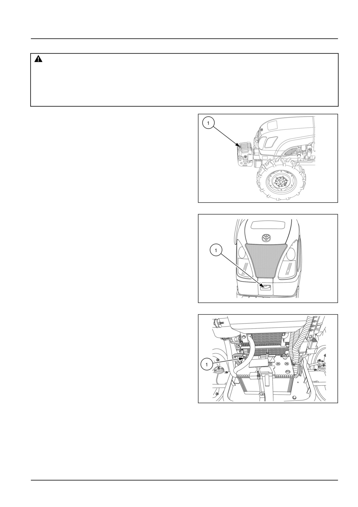
1. Remove the front weights (1).
GNIL14TR00829AA
1
2. Slide the lock (1) to right, hold and raise the hood.
GNIL14TR00533AA
2
3. Disconnect the battery terminals.
NOTE: Always disconnect the negative cable (1) first.
GNIL14TR00784AA
3
10.1 [10.001] / 3
Engine - Engine and crankcase
4. Unscrew the hood mounting bracket bolts (1) and nuts
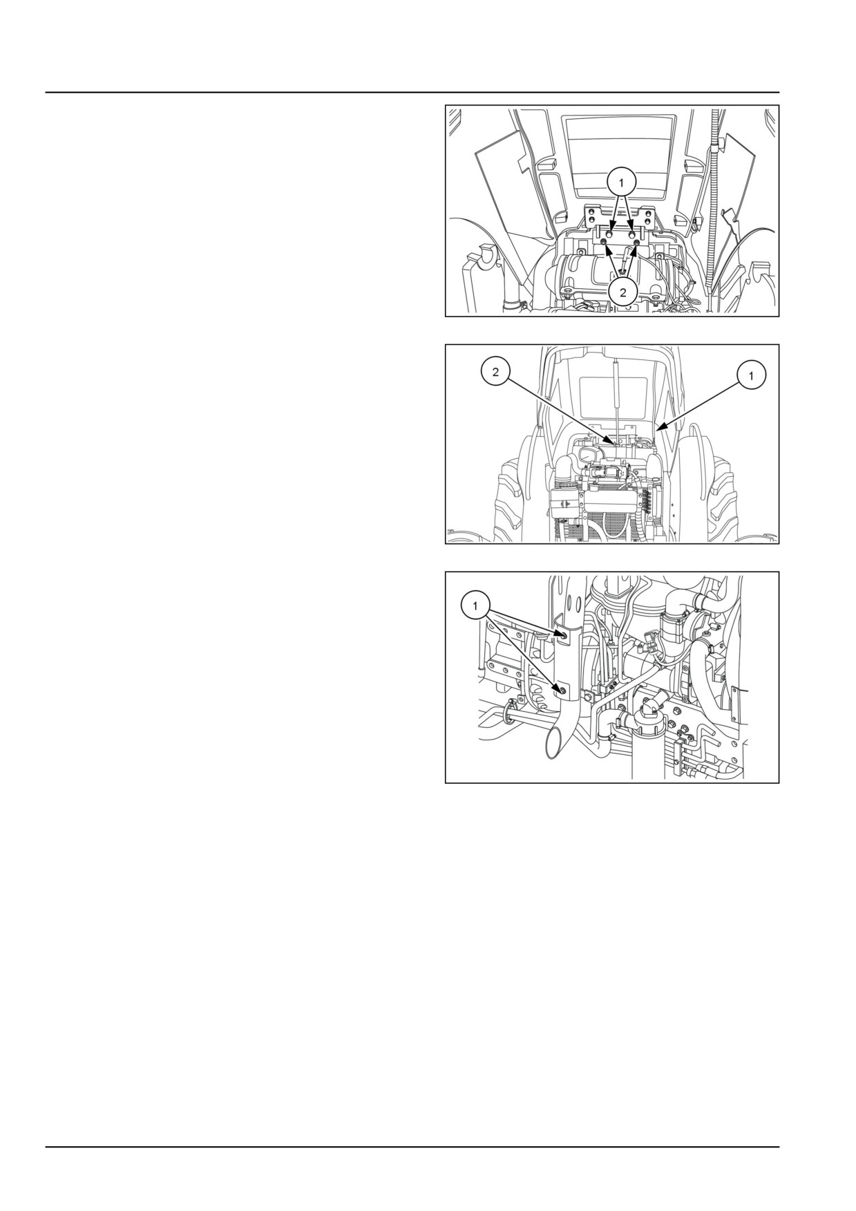
(2) from engine frame.
GNIL14TR00856AA
4
5. Disconnect headlight and horn harness connection (1).
6. Unscrew gas strut bolt (2) and remove the front hood.
GNIL14TR00822AA
5
7. Loosen the bolts (1) and remove the silencer guard.
GNIL14TR00631AA
6
10.1 [10.001] / 4
Engine - Engine and crankcase
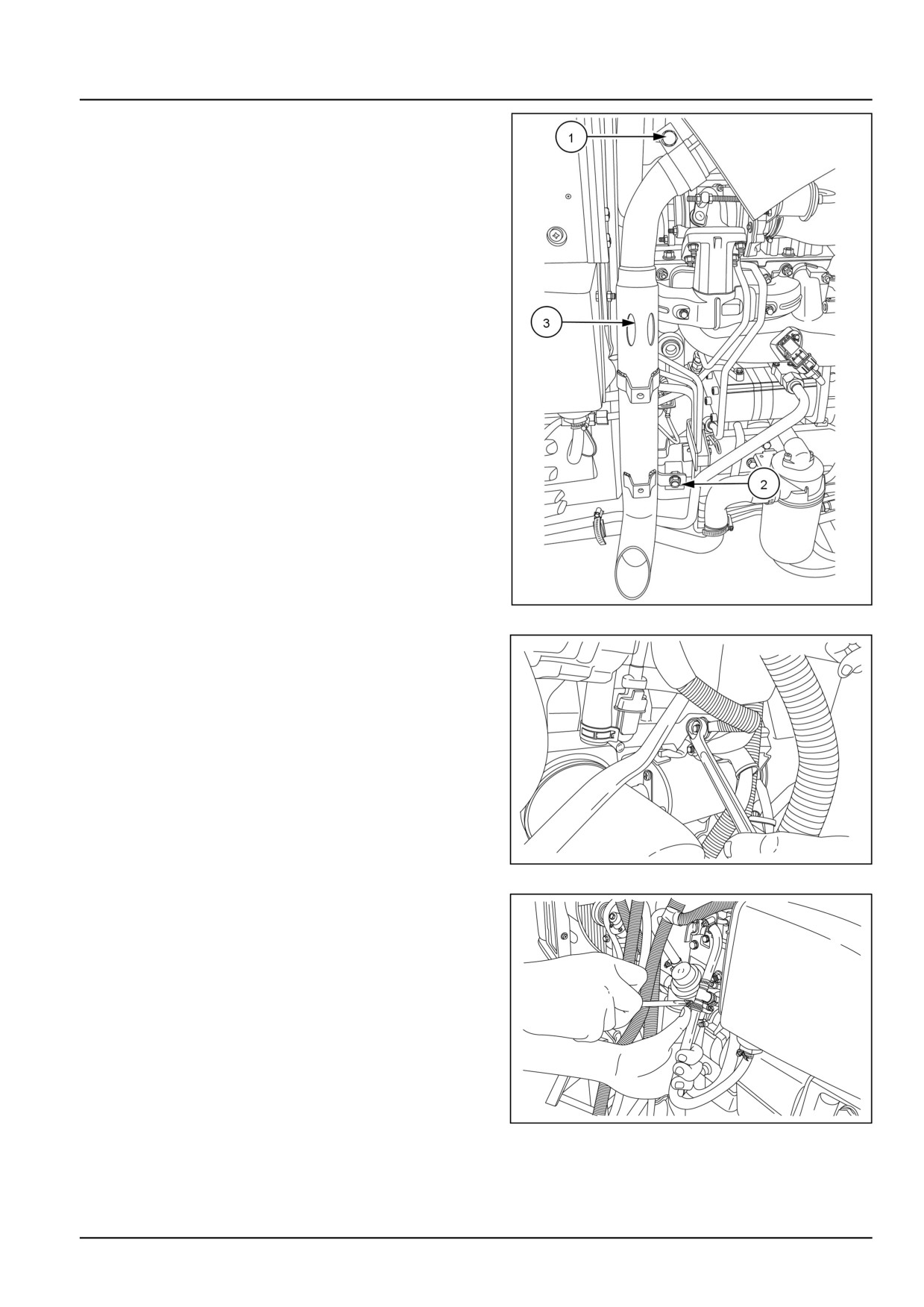
8. Loosen the silencer mounting bolts (1) and (2).
9. Remove the silencer (3).
GNIL14TR00611AA
7
10. Disconnect the electric connection (1) to starter motor.
GNIL14TR00713AA
8
11. Disconnect the fuel supply and return lines.
GNIL14TR00712AA
9
10.1 [10.001] / 5
Engine - Engine and crankcase
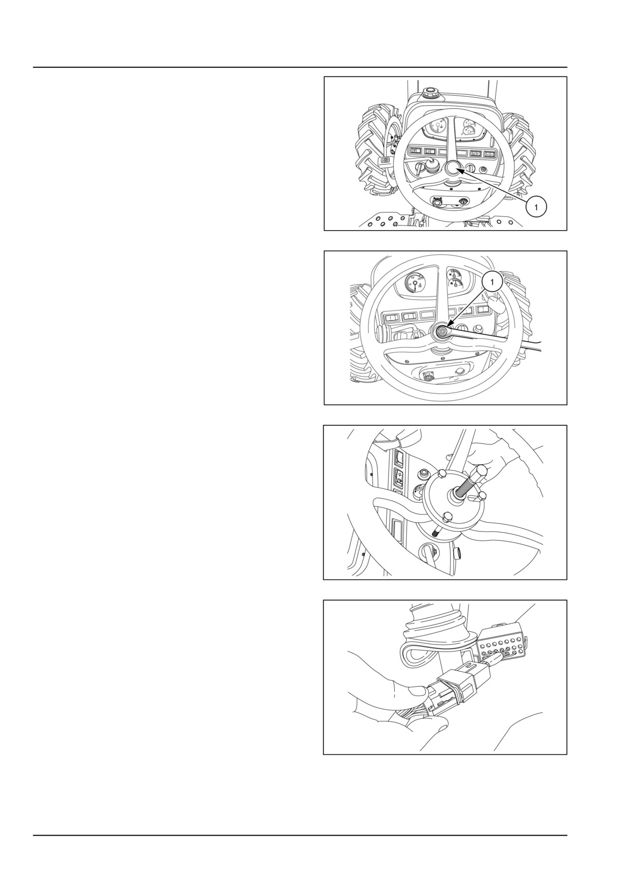
12. Remove the steering wheel cover (1).
GNIL14TR00512AA
10
13. Remove the steering wheel securing nut (1).
GNIL14TR00846AA
11
14. Remove the steering wheel using tool number
380001672, and 380003008.
GNIL14TR00704AA
12
15. Disconnect the wiring (1) on the steering column.
GNIL14TR00711AA
13
10.1 [10.001] / 6
Engine - Engine and crankcase
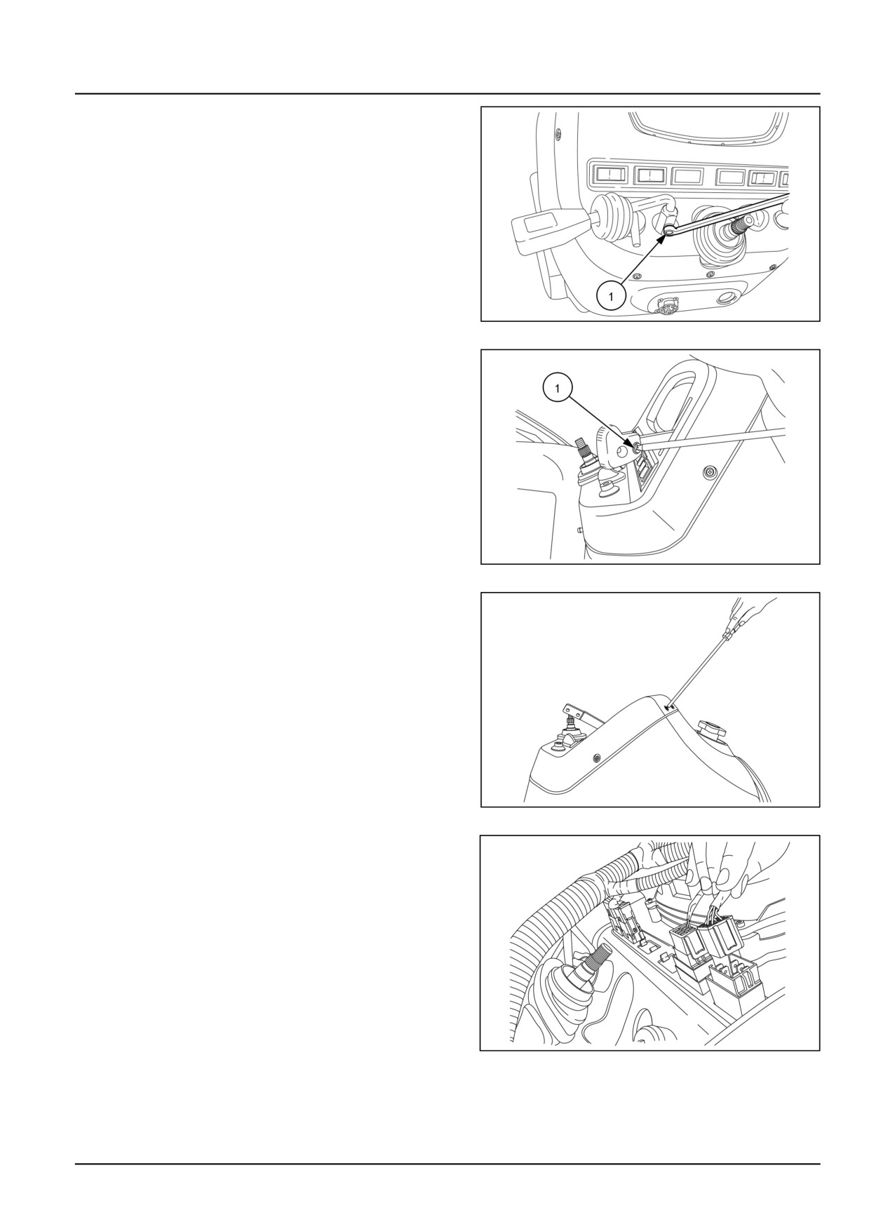
16. Loosen the bolt (1) and remove the shuttle lever.
GNIL14TR00705AA
14
17. Loosen the screw (1) and remove the hand throttle
knob.
GNIL14TR00706AA
15
18. Unscrew all the screws securing instrument panel to
the rear hood.
GNIL14TR00707AA
16
19. Pull out the instrument panel from the rear hood.
20. Disconnect all the wirings of the instrument cluster.
GNIL14TR00714AA
17
10.1 [10.001] / 7
Engine - Engine and crankcase
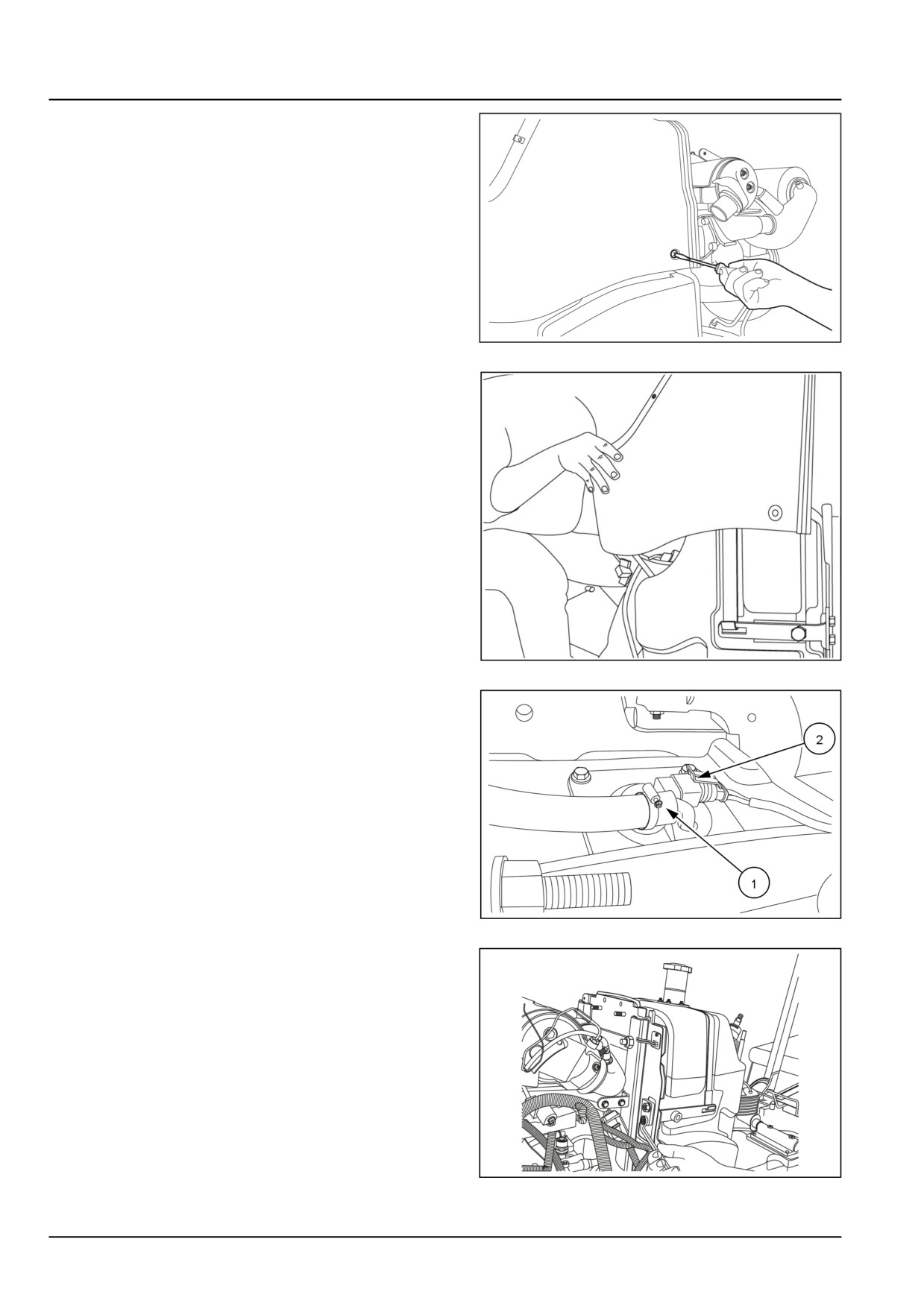
21. Remove pull to stop knob and then centre panel.
Unscrew all rear hood securing bolts and screws on
rear hood.
GNIL14TR00849AA
18
22. Lift and remove the rear hood.
GNIL14TR00715AA
19
23. Disconnect the diesel overflow pipe (1) on the fuel
tank.
24. Disconnect the fuel sensor electric connection (2).
GNIL14TR00719AA
20
25. Loosen the bolts and remove the bracket that holds
the fuel tank strap.
GNIL14TR00852AA
21
10.1 [10.001] / 8
Engine - Engine and crankcase
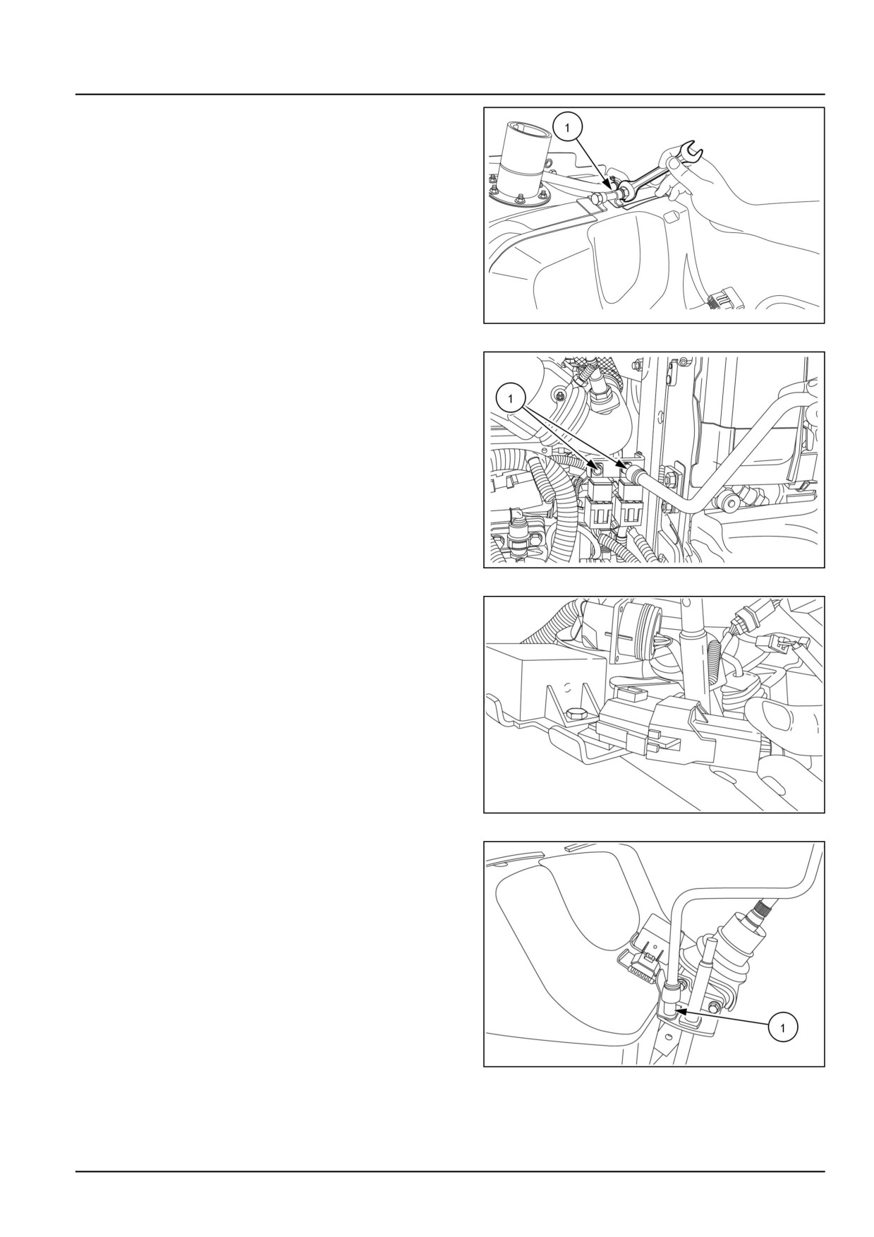
26. Loosen the bolts (1) and release the fuel tank strap.
NOTE: It is advisable to drain diesel from fuel tank if tank
is more than half filled.
GNIL14TR00709AA
22
27. Loosen the bolts (1) and remove the wiring couplers
at the rear of fuel tank.
GNIL14TR00851AA
23
28. Disconnect the wiring from the adaptor under the rear
hood.
GNIL14TR00855AA
24
29. Remove the bolts (1).
30. Remove the adaptor.
31. Remove the fuel tank.
GNIL14TR00727AA
25
10.1 [10.001] / 9
Engine - Engine and crankcase
32. Loosen the bolts (1) securing cover of the SCR (Se-
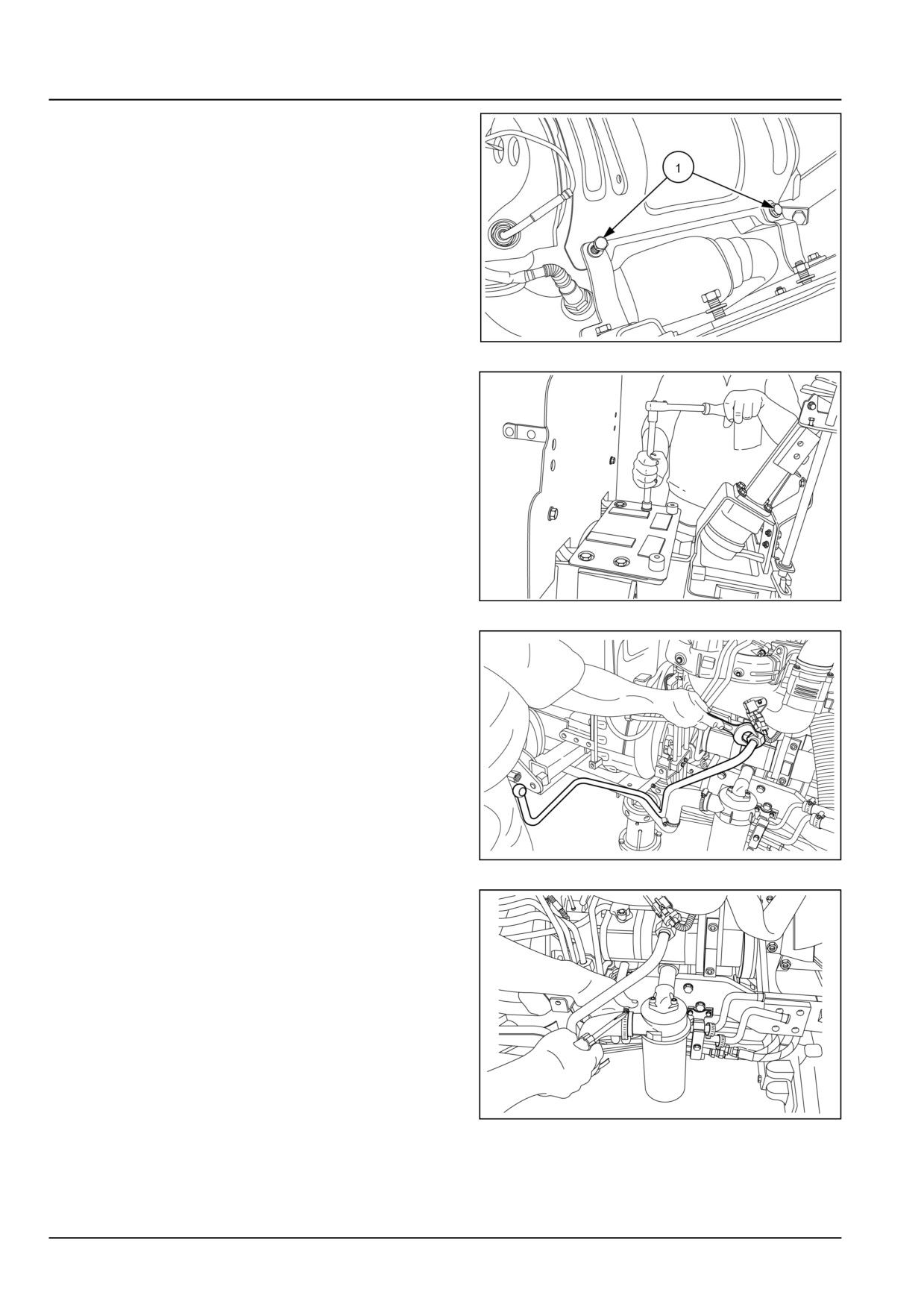
lective Catalytic Reduction) assembly to the fuel tank
support plate.
GNIL14TR00857AA
26
33. Remove all the bolts securing the fuel tank base plate
to the clutch housing.
34. Remove the fuel tank base plate.
GNIL14TR00850AA
27
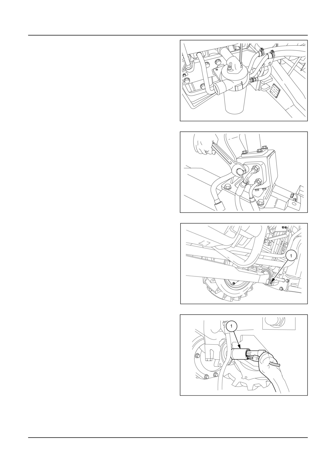
35. Disconnect the hydraulic line between the pump and
the mid mount valve.
GNIL14TR00783AA
28
36. Loosen the clamp and remove the suction pipe from
the hydraulic filter.
GNIL14TR00725AA
29
10.1 [10.001] / 10
Engine - Engine and crankcase
37. Loosen the set screws and remove the hydraulic filter.
GNIL14TR00728AA
30
38. Disconnect the power steering hoses on the steering
motor.
GNIL14TR00740AA
31
39. Loosen the bolts (1) of the 4WD shaft cover.
GNIL14TR00823AA
32
40. Remove the circlip and slide the coupler (1) backward.
GNIL14TR04359AB
33
10.1 [10.001] / 11
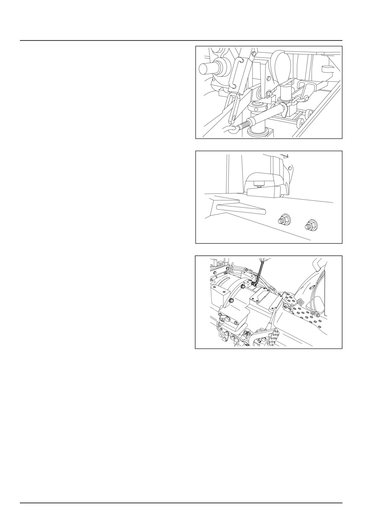
Engine - Engine and crankcase
41. Position splitting trolley, special tool number 292320,
with engine supports in position.
42. Block front wheels at the front and back using suitable
wedges.
GNIL14TR04779AA
34
43. Support the engine at the back of the front axle.
44. Position wedges between axle and support to prevent
articulation.
GNIL14TR04781AA
35
45. Loosen the bolts securing the engine to the centre
housing.
46. Wheel the centre housing and rear wheels away from
the engine.
GNIL14TR00753AA
36
10.1 [10.001] / 12
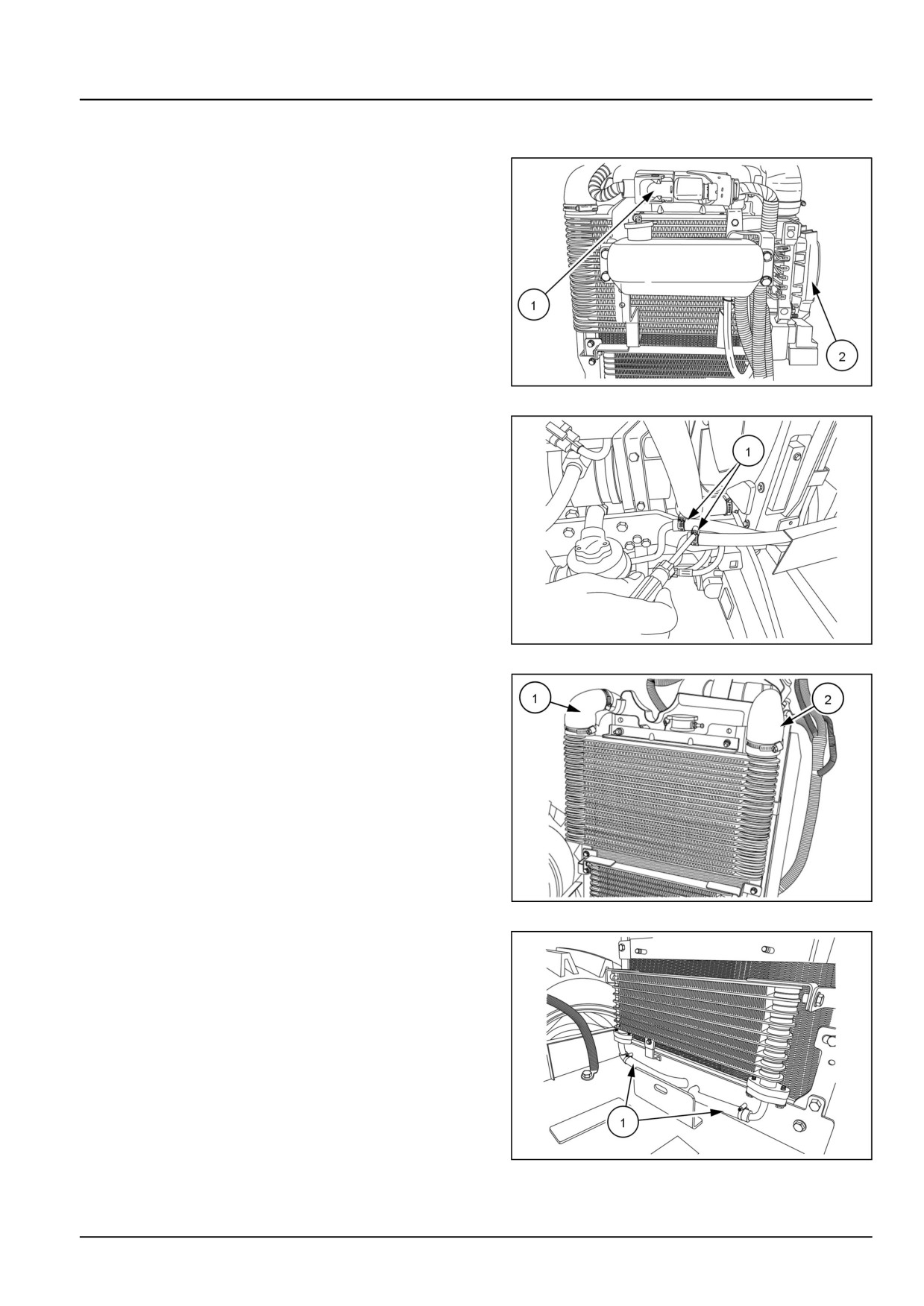
Engine - Engine and crankcase
Separating front axle from engine
With engine previously separated from centre housing
47. Remove the electrical couplers (1) from Engine Con-
trol Unit (ECU) and (2) for rear lamps, flasher unit, fuse
box etc.
GNIL14TR00757AA
37
48. Disconnect the steering hoses (1).
GNIL14TR00758AA
38
49. Disconnect the hoses (1) from the intercooler.
GNIL14TR00702AA
39
50. Disconnect the pipes (1) from the fuel cooler.
GNIL14TR00703AA
40
10.1 [10.001] / 13
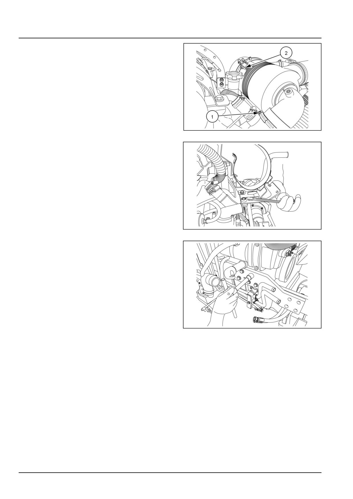
Engine - Engine and crankcase
51. Loosen the clamp (1) on the air inlet hose.
52. Loosen the bolt (2) and remove the air cleaner assem-
bly.
GNIL14TR00720AA
41
53. Loosen the bolts and remove the air cleaner mounting
bracket.
GNIL14TR00860AA
42
54. Support the front axle at the front bracket.
55. Support the engine using a suitable hoist.
56. Remove the buckle up bolts and set screws between
the engine and front axle support. Carefully lift the
engine from the front axle support.
57. Make sure that all the wires and tubes are discon-
nected. Place the engine on a suitable stand for re-
pair.
GNIL14TR00755AA
43
10.1 [10.001] / 14
Engine - Engine and crankcase
Engine - Install
For installation, follow the reverse order of removal.
See Instrument cluster - Install (55.408) for the instal-
lation of the instrument cluster.
10.1 [10.001] / 15
Index
Engine - 10
Engine and crankcase - 001
Engine - Install
15
Engine - Remove
3
10.1 [10.001] / 16
Engine - 10
Crankshaft and flywheel - 103
Workmaster™ 50
Workmaster™ 60
Workmaster™ 70
10.2 [10.103] / 1
Contents
Engine - 10
Crankshaft and flywheel - 103
SERVICE
Engine flywheel
Remove
3
Inspect
5
10.2 [10.103] / 2
Engine - Crankshaft and flywheel
Engine flywheel - Remove
WARNING
Avoid injury!
Handle all parts carefully. Do not place your hands or fingers between parts. Use Personal Protec-
tive Equipment (PPE) as indicated in this manual, including protective goggles, gloves, and safety
footwear.
Failure to comply could result in death or serious injury.
W0208A
It is necessary to split the tractor between engine and
transmission housing to gain access to the clutch. See
engine removal section.
1. Remove the bolts (1). Separate the transmission hous-
ing from engine.
GNIL14TR00753AA
1
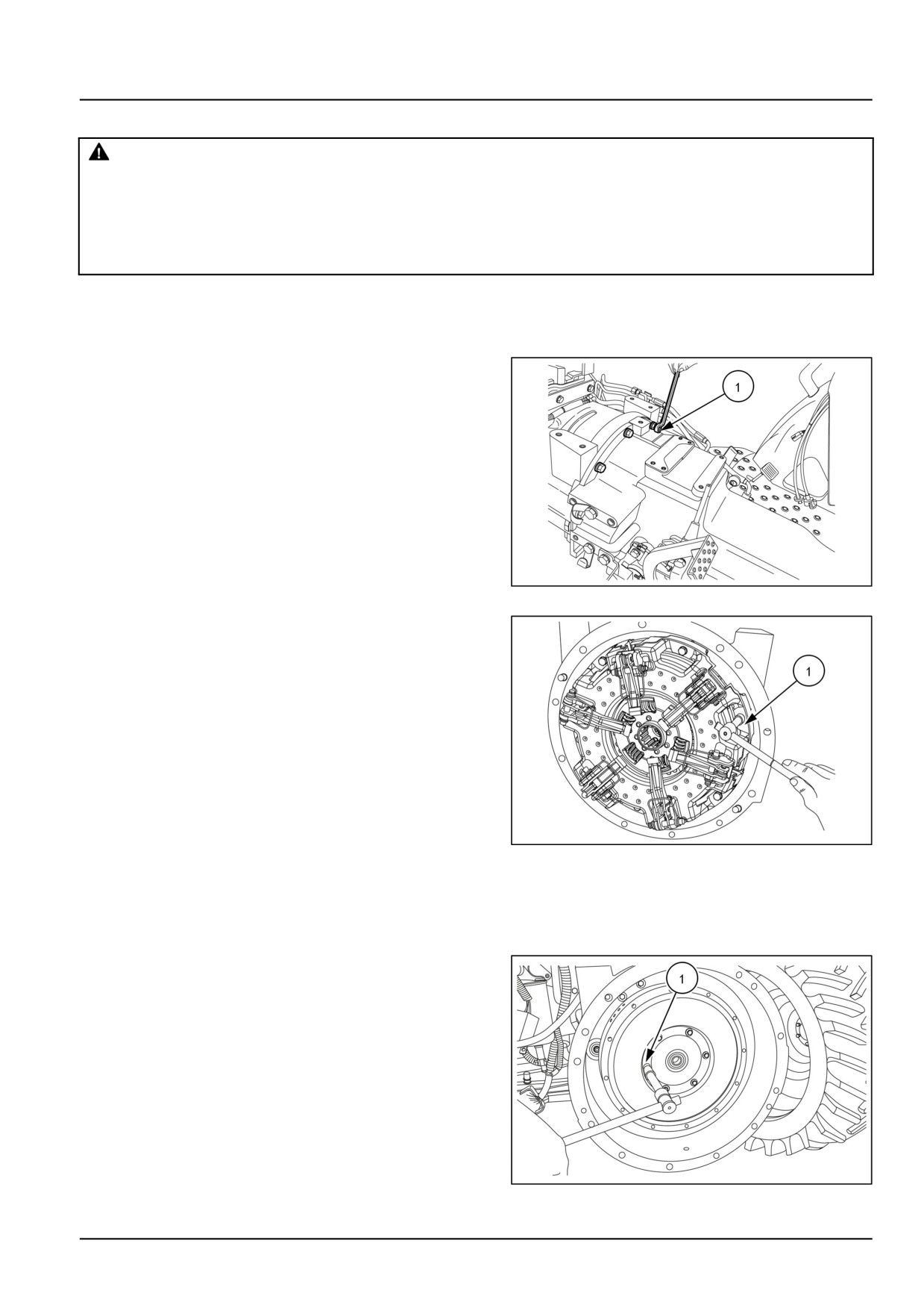
2. Remove the bolts (1) which retains the clutch assembly
to the engine fly wheel and slacken the two remaining
bolts.
GNIL14TR00754AA
2
3. Insert centralizing pin special tool number 380000612
in clutch plate shaft seats back off the two remain-
ing bolts and remove assembly completely. Retrieve
Power Take-Off (PTO) clutch disc.
4. Remove the bolts (1) and retrieve the pilot bearing as-
sembly.
GNIL14TR00769AA
3
10.2 [10.103] / 3
Engine - Crankshaft and flywheel
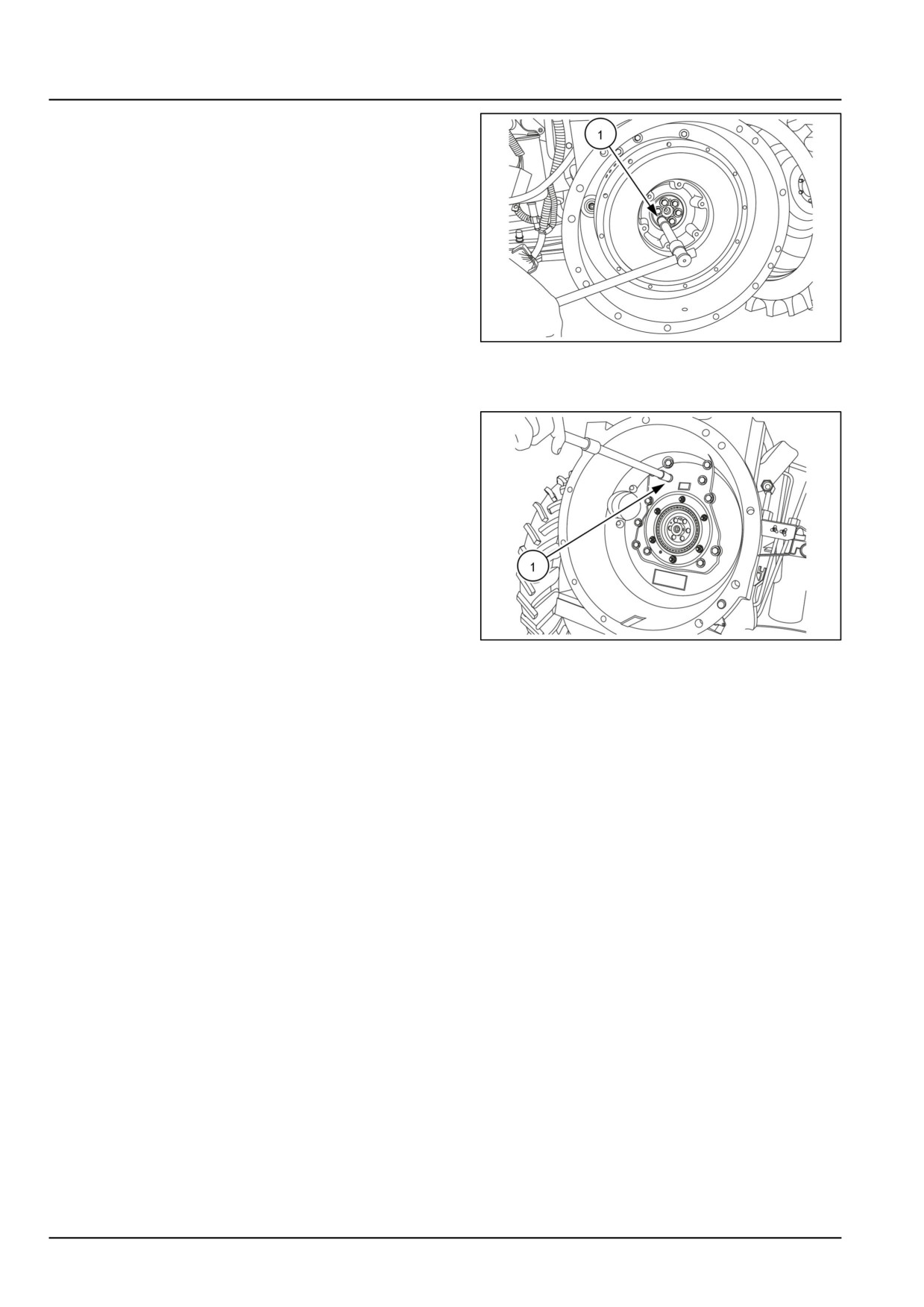
5. Remove the bolts (1) and take out the flywheel from the
main clutch housing.
GNIL14TR00770AA
4
Clutch housing separation from the engine (if necessary)
6. Place a suitable support. Remove the bolts (1) and
separate the clutch housing.
GNIL14TR00771AA
5
10.2 [10.103] / 4
Engine - Crankshaft and flywheel
Engine flywheel - Inspect
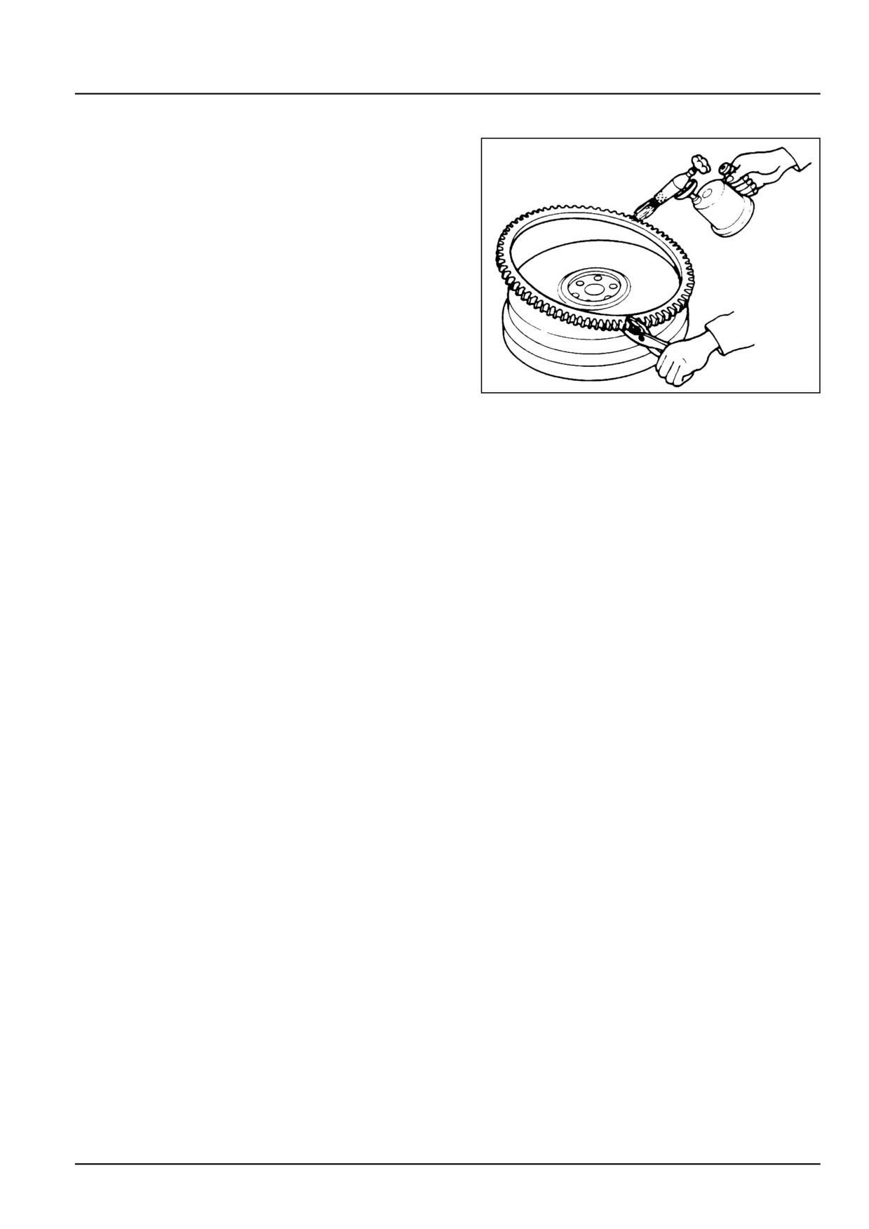
1. Inspect the ring gear for cracked, broken, chipped, or
worn gear teeth. If found damaged, replace the ring
gear.
2. If necessary, remove the starter ring gear using a ham-
mer and chisel to crack the ring gear.
3. To reinstall a new ring gear, heat the new ring gear
to 120 - 150 °C (245 - 300 °F) from the inside only.
Be careful not to overheat the ring gear teeth. Use a
temperature sensitive crayon to mark the inside of the
ring gear. Quench the ring gear quickly to obtain a good
shrink fit onto the flywheel.
20093403
1
10.2 [10.103] / 5
//////////////////////////