New Holland Tractor Workmaster 50 / Workmaster 60 / Workmaster 70 / Tier 4B (final). SERVICE MANUAL - page 4
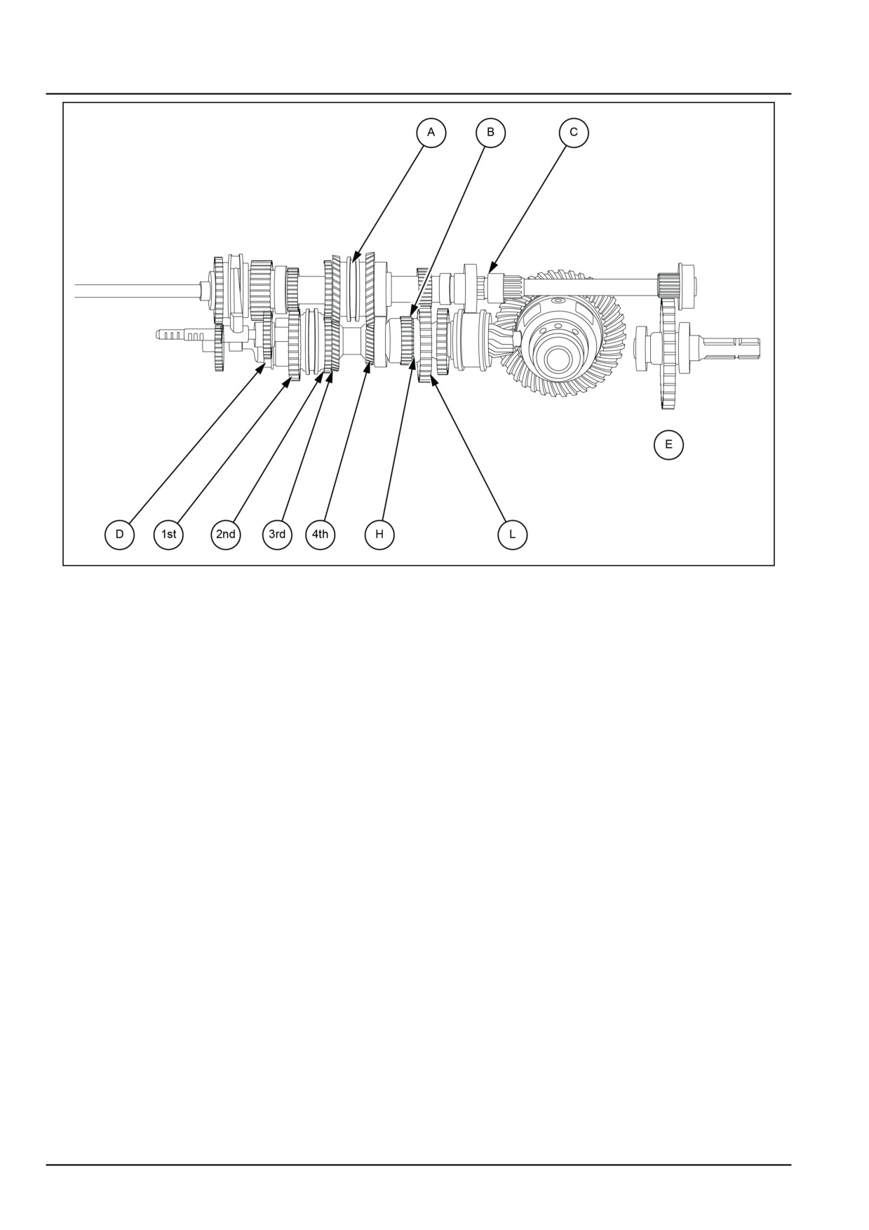
Transmission - Mechanical transmission
GNIL14TR04107FB
3
A Main gear lever (1st/2nd & 3rd/4th)
E PTO 540
B Range selector lever (H/L)
H High
C PTO Coupler
L Low
D Reverse
The speeds are shifted by meshing gears 1st (4), 2nd (5), 3rd (6), and 4th (7) in succession with the gearbox driven
shaft. This is done by means of gear couplers (9) and (10). If coupler (9) is shifted, say to the left, its internal teeth will
connect additional gear ring of 1st gear (4) with toothed bushings secured on the driven shaft. As a result, 1st gear (4)
will rotate together with the driven shaft and transmit rotation to pinion shaft via range shaft (2). When gear coupler
(9) is shifted to the right, the driven shaft will become rigidly connected with 2nd gear (5) having a larger number of
teeth than 1st gear. As a consequence, the pinion shaft will rotate faster than the previous speed.
Similarly by shifting gear coupler (10) to left pinion shaft is driven by 3rd gear (6) via range shaft and by shifting to
right pinion shaft is driven by 4th gear (7) via range shaft and speed of the pinion shaft varies according to the number
of teeth on the gears (6) and (7).
Range gear can be selected by shifting the range gear coupler (11) to left or right. For getting high range, shifting
coupler to left engages cluster gear directly to pinion shaft and pinion shaft receives the rotation from any one of the
gears 1st, 2nd, 3rd and 4th depending on the position of gear couplers (9) and (10) through driven shaft (16) and
range shaft (2).
For low gear range coupler (11) have to be shifted to right and pinion shaft receives rotation via driven shaft (16) and
range shaft (2). Since gear (12) has less number of gears teeth, as a consequence, the pinion shaft will rotate slower
than high range.
For high gear range coupler (11) have to be shifted to the left and pinion shaft receives a rotation directly from driven
shaft (16).
For engaging reverse gear, shift reverse gear fork to right, power flow is from input shaft via drive shaft to reverse
drive (14) gear (18) acts as intermediate gear between reverse drive gear (14) and reverse gear (13) and changes the
direction of rotation of pinion shaft. Depending on the position of range gear coupler (11) high reverse or low reverse
are obtained.
21.1 [21.114] / 10
Transmission - Mechanical transmission
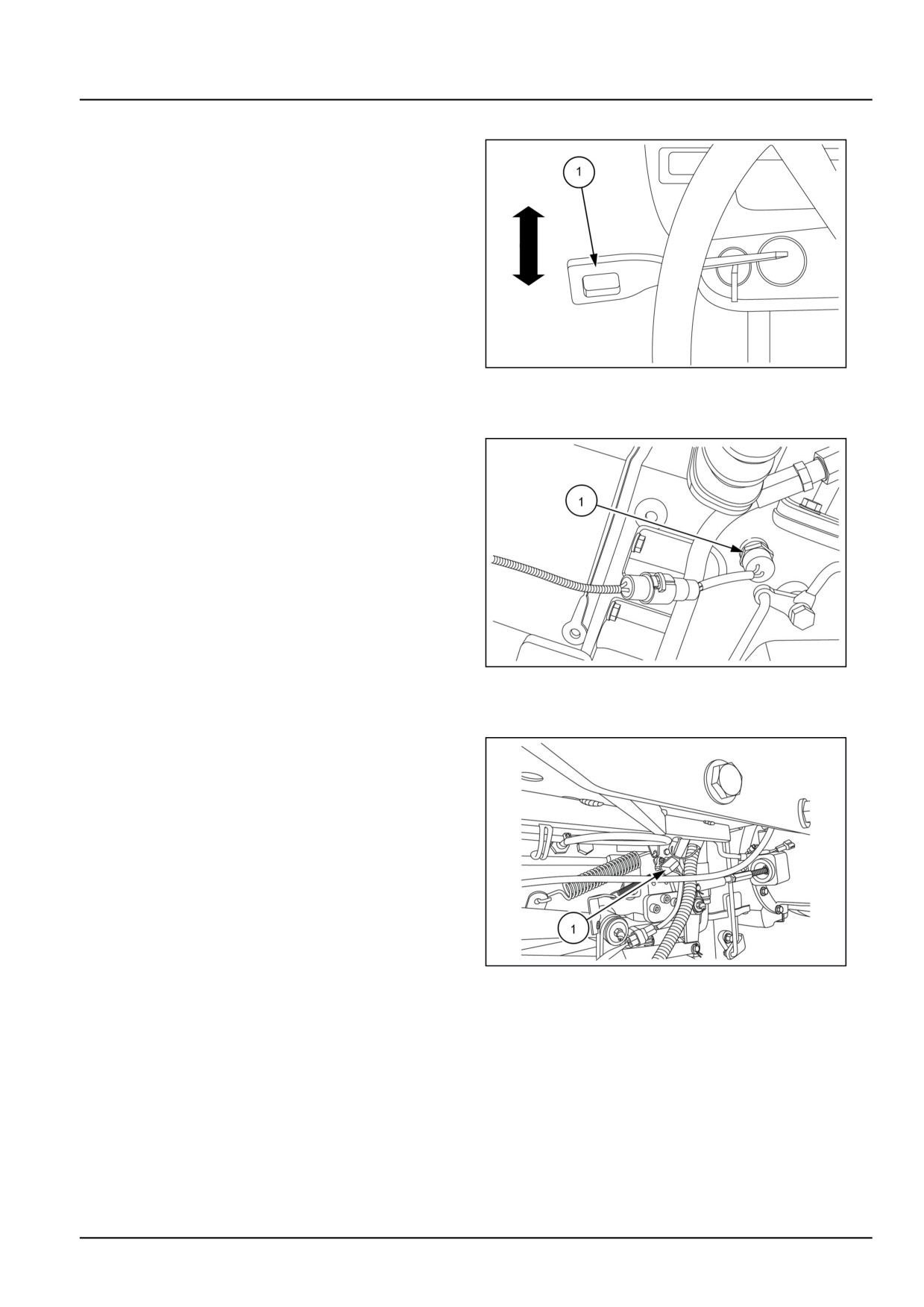
8 + 8 Synchro shuttle
The synchro shuttle transmission is ideal for application
which require frequent changes of direction. The oper-
ator has to press clutch pedal and move shuttle lever to
change direction of travel. Shift lever (1) to front for for-
ward and rear to get reverse direction.
NOTE: The shuttle lever must be in the neutral (middle)
position to activate the safety start system, which allows
the engine to start.
GNIL14TR04110AB
4
Transmission range safety switch
The transmission range safety switch (1) is a single-pole,
single-throw, switch located along the left side of the trans-
mission. The switch is activated by the range shift lever.
When the range is in neutral, the switch is closed to allow
current to flow to the neutral start relay.
NOTE: The range shift rail operates the safety switch.
Notches in the shift rail accept the balk pin, extending the
plunger in the safety switch, when the range lever is in the
neutral position. This completes the circuit and allows the
tractor to start.
GNIL14TR00870AA
5
Transmission clutch safety switch
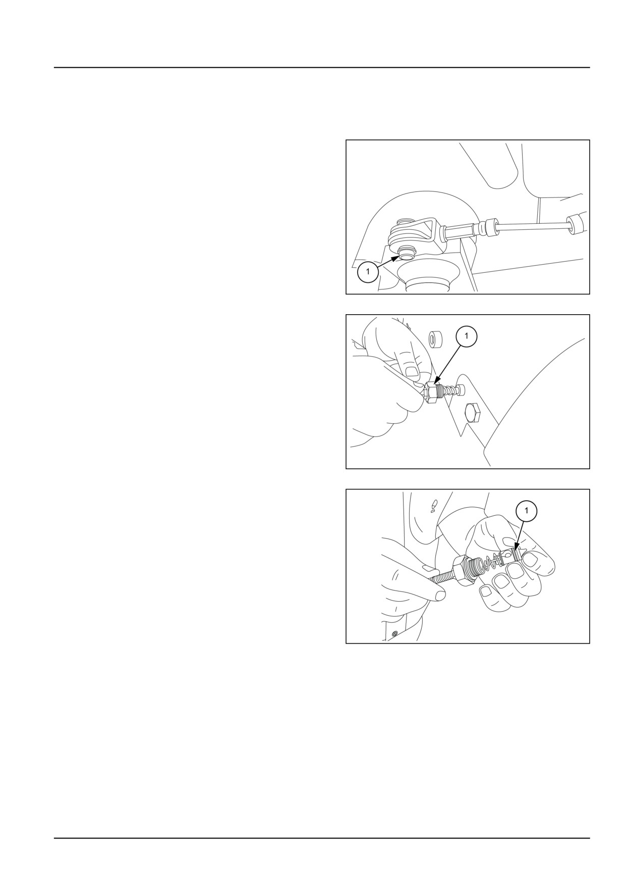
The transmission clutch safety switch (1) is a single throw-
style switch, located underneath the left side platform of
the tractor. The switch is activated by the clutch pedal.
When clutch pedal is depressed, the switch closes com-
pleting the circuit.
GNIL14TR00796AA
6
21.1 [21.114] / 11
Transmission - Mechanical transmission
Drive shaft - Service instruction
NOTE: Please read this carefully before starting assembly
or disassembly operations.
Precaution at flange and tool ends
While hammering at flange and tool ends during re-
moval or installation, attention must be paid to the vari-
ous phases. Functioning and integrity of tool as well as
various components must not be endangered.
Reassembling methods
Adequate holding equipment should be used for re-
assembling group.
Lifting system will be necessary for reconnecting, disas-
sembling and reassembling the ring gear or for holding
the gear box.
Use cross section drawings to ease assembly and dis-
assembly operations.
Recommendations regarding lubrication
It is very important to use proper lubricants and to main-
tain a constant level of correct lubrication.
Right operational temperature is to be maintained.
Shaft seals
Respect the following recommendations during seal
and gasket assembly:
• Clean shaft very carefully and ensure that the part in
contact with the rings is not damaged, cut or out of
roundness.
• Assemble the seals so that the lips is fitted towards
the oil side.
• Lubricate seal lips (use oil ) and fill 3/4 of seal cavity
with grease.
• Use appropriate driver. Do not use a hammer di-
rectly on the seals.
• Do not damage the seals while assembling the shaft.
O-ring
Lubricate adequately before inserting them at the right
place so as to avoid rolling while assembling shaft.
Adjusting shims
Use appropriate adjusting shims and measure each
one separately.
Complete group measurement or stamping on the shim
is not always reliable check.
21.1 [21.114] / 12
Transmission - Mechanical transmission
Bearings
Use correct pullers for bearings removal.
Clean, lubricate and inspect well before reassembling
the bearings.
The spiral elastic pins do not need such adjustment.
Sealing
Use sealants as specified. ensure that parts to be
sealed are clean, dry and grease free.
Oil drain
Before disassembly oil should be drained out from the
group.
WARNING
Disposal of used oil must be done according to the laws.
Cleaning
1. All parts in motion (gears, bearings, etc) are to be
washed accurately with parts cleaning solution.
2. Petrol and watery alkaline solutions are to be avoided.
3. Do not wash with stream or hot water as it will be very
difficult to eliminate surface humidity.
4. Dry all parts with a rag or air jet to avoid scratching from
abrasive residuals.
5. All surfaces should be covered with lubricant so as to
protect it from future oxidation.
Inspections
1. Examine accurately that all bearings, external rings
which may be still stuck in their position pivot pins on
which rolls rotate and replace those which are worn out
or damaged.
2. Gears should not be damaged and teeth should not be
excessively worn. Smoothness of the teeth should not
be deteriorated.
3. Control all grooves. Assure that they are not worn out
or damaged.
4. Replace damaged parts with original spare parts.
5. After disassembly, replace seals on rotating shaft.
21.1 [21.114] / 13
Transmission - Mechanical transmission
Mechanical transmission - Remove
WARNING
Avoid injury!
Handle all parts carefully. Do not place your hands or fingers between parts. Use Personal Protec-
tive Equipment (PPE) as indicated in this manual, including protective goggles, gloves, and safety
footwear.
Failure to comply could result in death or serious injury.
W0208A
DANGER
Heavy objects!
Lift and handle all heavy components using lifting equipment with adequate capacity. Always support
units or parts with suitable slings or hooks. Make sure the work area is clear of all bystanders.
Failure to comply will result in death or serious injury.
D0076A
NOTE: To remove the transmission housing from the tractor, tractor has to be split at clutch and transmission housing.
Fenders, hydraulic housing, three point linkage, rear tires and final drive housing have to be removed from the tractor.
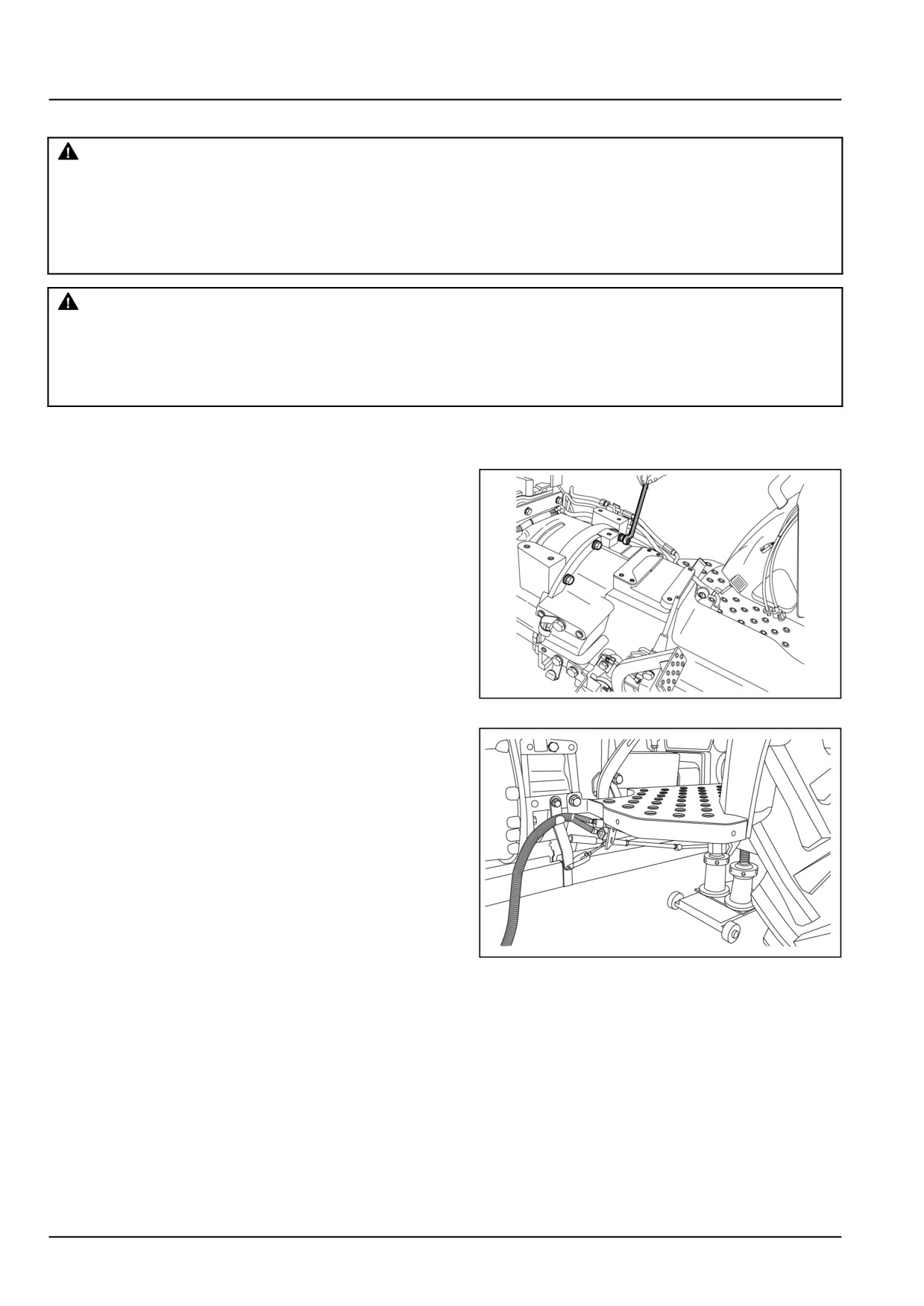
1. Loosen the bolts and remove the transmission assem-
bly from the tractor. See engine removal section.
GNIL14TR00753AA
1
2. Loosen bolts securing foot boards on left-hand side
and right-hand side fenders. Disconnect all the wirings.
See Protections and footboards - Remove (90.118).
GNIL14TR00767AA
2
21.1 [21.114] / 14
Transmission - Mechanical transmission
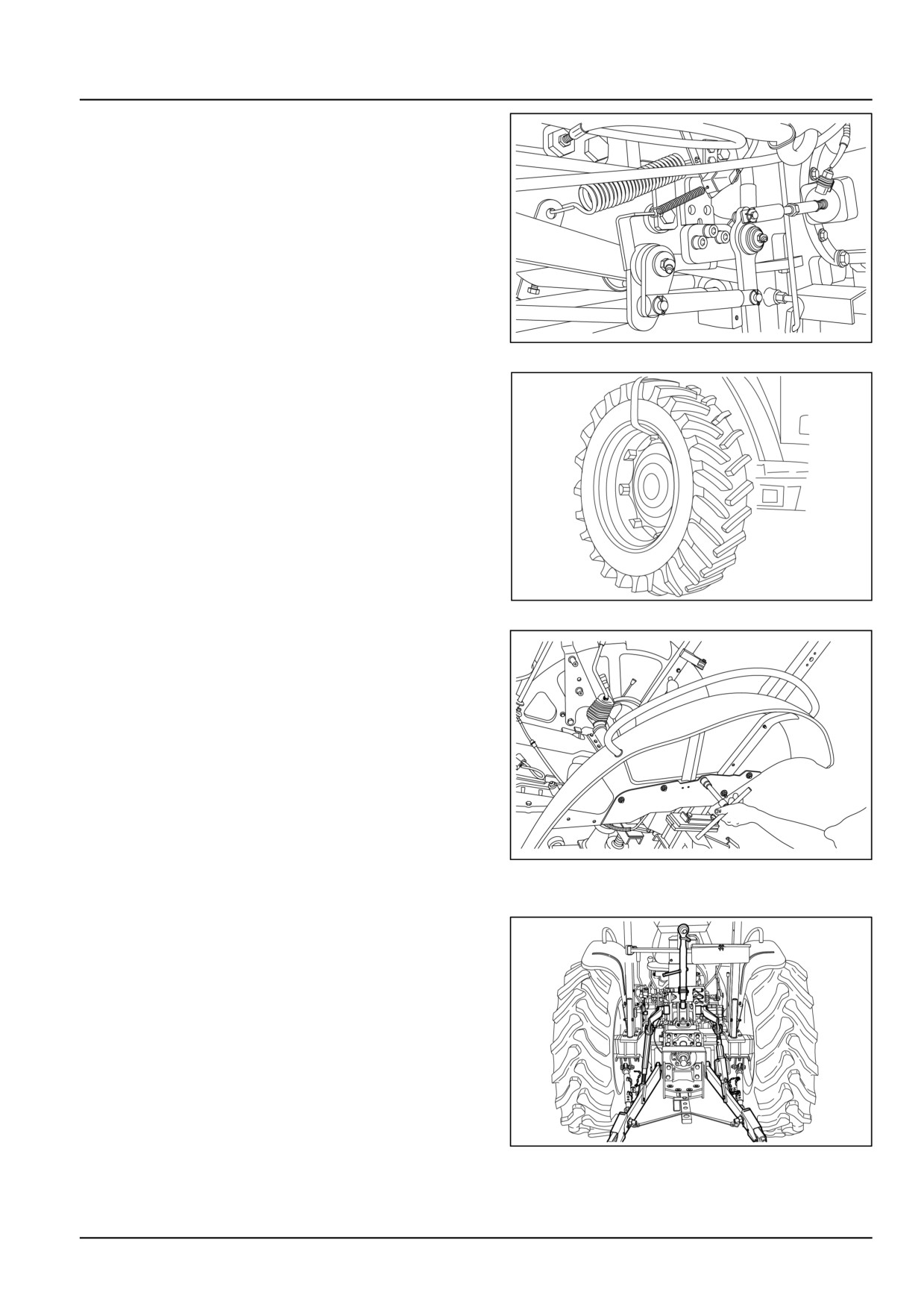
3. Disconnect the clutch linkages and the brake linkages.
GNIL14TR00766AA
3
4. Remove both the left-hand and right-hand side wheels.
GNIL14TR04016AB
4
5. Loosen the bolts (1) and remove fenders from both
sides.
Drain oil from transmission housing.
GNIL14TR00790AA
5
6. Disconnect all the hydraulic lines.
7. Remove three point linkages from the tractor.
GNIL14TR00562AA
6
21.1 [21.114] / 15
Transmission - Mechanical transmission
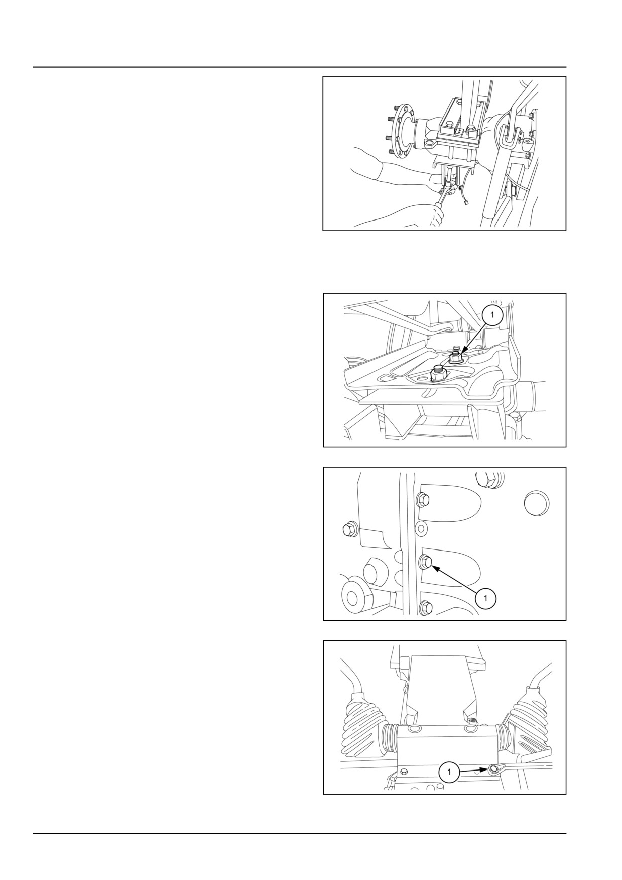
8. Remove the ROPS (Roll Over Protection Structure)
from the tractor.
GNIL14TR00865AA
7
9. Place splitting trolley (special tool number: 292320) (1)
under the tractor. Place a suitable stand under both
side of the final drive housing.
10. Loosen the bolts (1), disconnect the wiring and re-
move operator’s seat.
GNIL14TR04021AB
8
11. Loosen the transmission and centre housing coupling
bolts (1). Use a suitable hoist and lift the assembly.
GNIL14TR04022AB
9
12. Loosen bolts (1) and remove top cover along with
gearshift levers.
GNIL14TR04124AB
10
21.1 [21.114] / 16
Transmission - Mechanical transmission
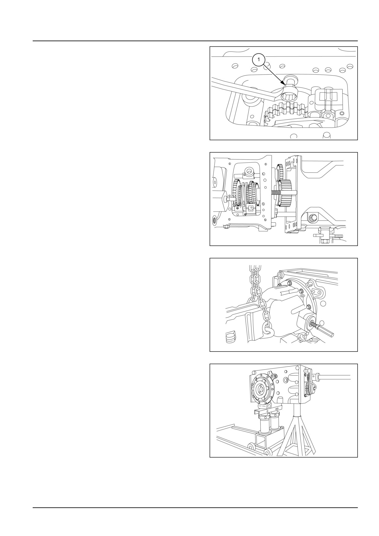
13. Loosen the bolt (1) as shown in figure before separat-
ing the transmission housing from clutch housing.
GNIL14TR04024AB
11
14. Separate the clutch and transmission housing.
GNIL14TR04128AA
12
15. Wrap chain or nylon rope on the final drive housing
and connect it to a hoist. Loosen the attaching bolts
and remove the final drive housing.
16. Repeat for the final drive housing on the other side.
17. Loosen the bolts securing hydraulic housing on trans-
mission housing and lift the housing using suitable
hoist.
GNIL14TR04026AA
13
18. Place transmission housing on a suitable stand.
GNIL14TR04027AA
14
21.1 [21.114] / 17
Transmission - Mechanical transmission
Mechanical transmission - Disassemble - Intermediate plate
WARNING
Heavy objects!
Lift and handle all heavy components using lifting equipment with adequate capacity. Always support
units or parts with suitable slings or hooks. Make sure the work area is clear of all bystanders.
Failure to comply could result in death or serious injury.
W0398A
CAUTION
Pinch hazard!
Always use suitable tools to align mating parts. DO NOT use your hand or fingers.
Failure to comply could result in minor or moderate injury.
C0044A
To remove the intermediate plate and reverse gear.
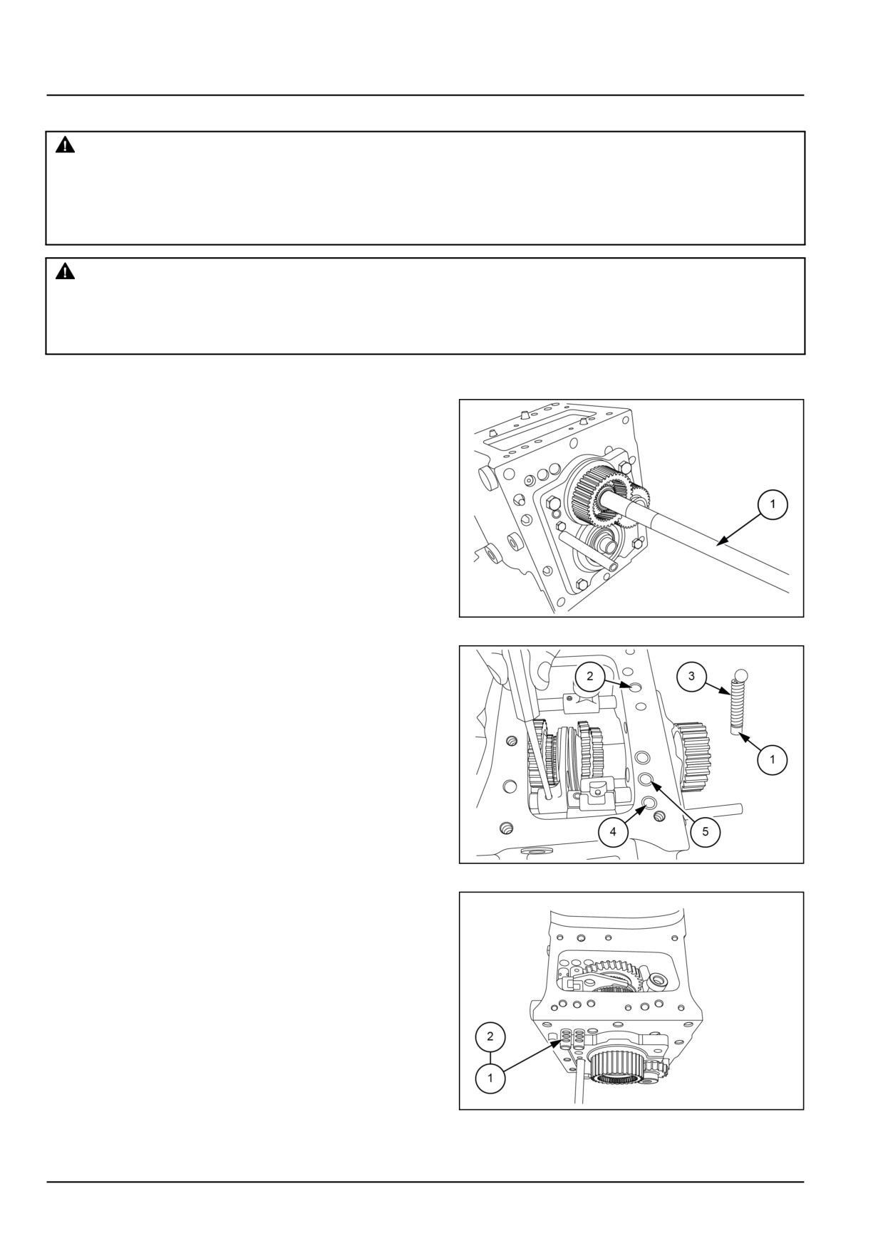
1. Remove Power Take-Off (PTO) shaft (1).
GNIL14TR04150AB
1
2. Remove all roll pins from gear rails to make dismantling
easy. Remove the springs and balls.
NOTE: Remove plug (1), from housing as shown at (2),
from where Hi/Low rail passes, retrieve spring and ball (3)
of Hi/Low rail. Retrieve balls and springs from location (4)
and (5).
GNIL14TR04132AB
2
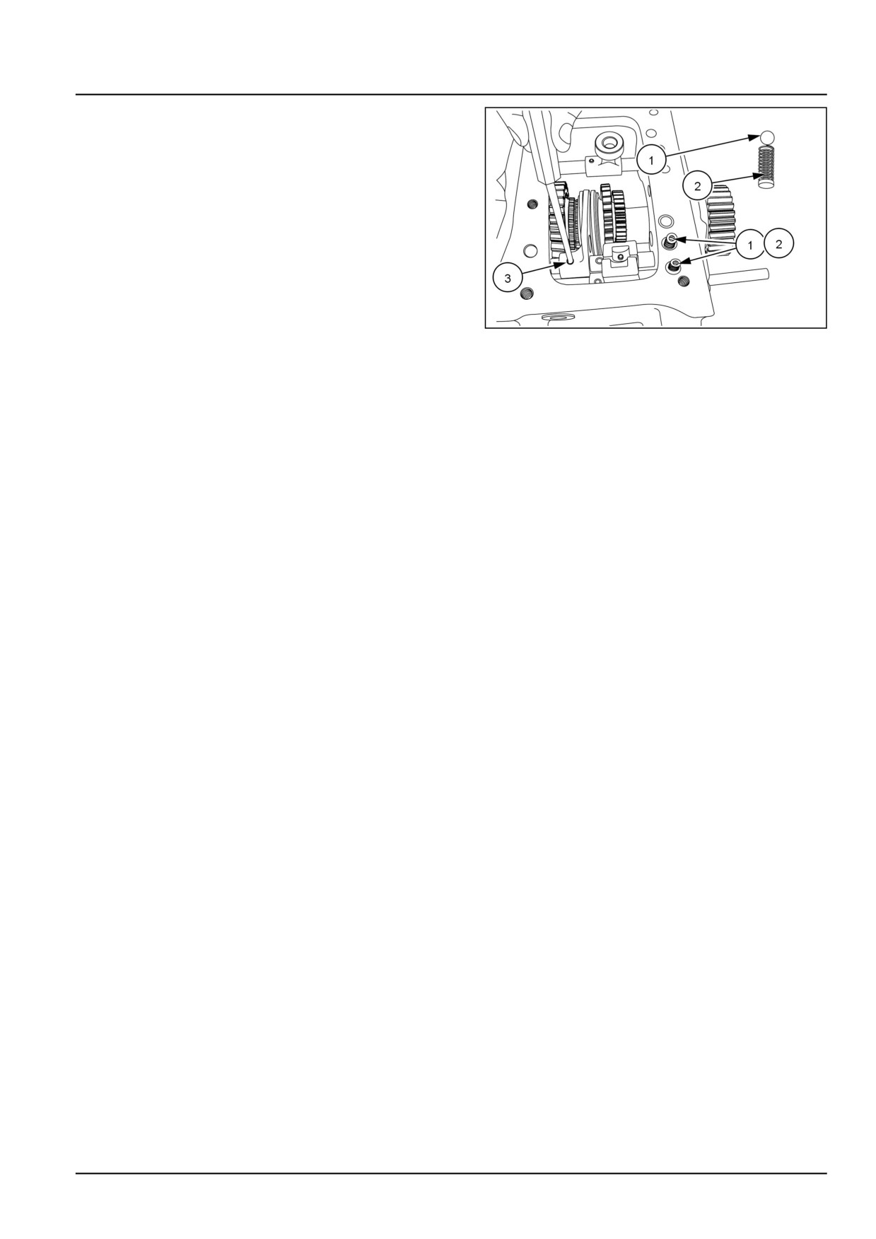
3. Remove the springs (1) and balls (2), with the help of a
magnetic tool.
4. Remove all the rails and take out gates, forks.
NOTE: Bring all the gears neutral position to remove rails
and retrieve balls from crown side.
GNIL14TR04133AB
3
21.1 [21.114] / 18
Transmission - Mechanical transmission
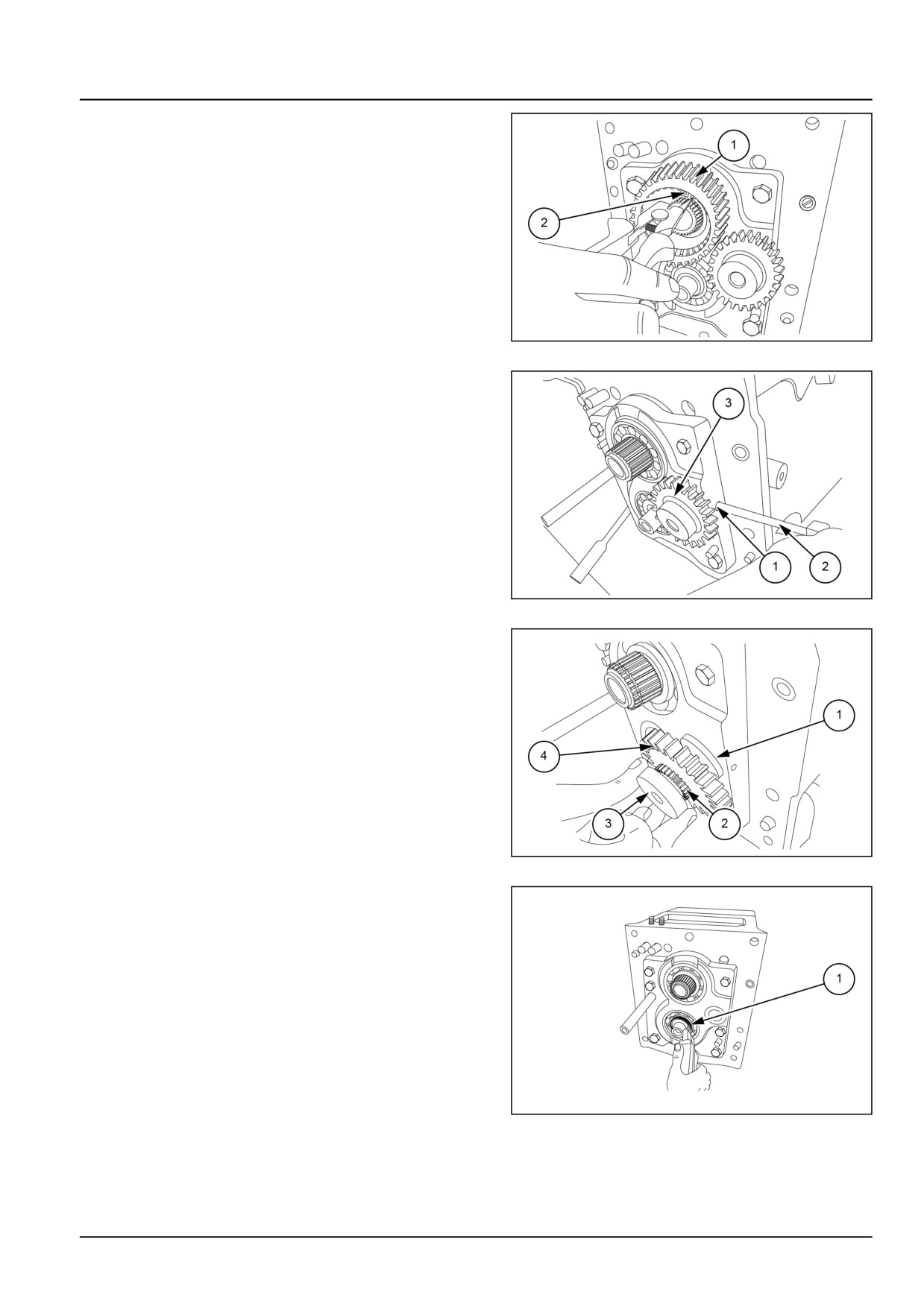
5. Remove the snap ring (2) securing the reverse drive
gear.
6. Remove the reverse drive gear (1) from drive shaft.
GNIL14TR04147AB
4
7. Unscrew the reverse intermediate gear shaft locking
screw (1) with a screw driver (2).
8. Remove the idler gear (3).
GNIL14TR04135AB
5
9. Remove the spacer (1), needle bearing (2), and re-
verse intermediate gear pin (3), along with reverse in-
termediate gear (4).
GNIL14TR04136AB
6
10. Remove the snap ring (1) securing the driven shaft
bearing.
GNIL14TR04137AB
7
21.1 [21.114] / 19
Transmission - Mechanical transmission
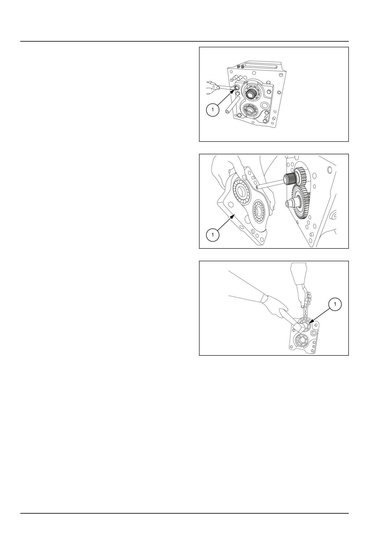
11. Remove all the bolts (1) securing the intermediate
plate.
GNIL14TR04138AB
8
12. Remove the intermediate plate (1) along with the bear-
ings.
GNIL14TR04139AB
9
13. Remove the ball bearings from the intermediate plate
by expanding the retaining rings (1).
GNIL14TR04140AB
10
21.1 [21.114] / 20
Transmission - Mechanical transmission
Mechanical transmission - Inspect - Intermediate plate
Clean and inspect the shift fork, shift rail, coupler, hub,
bearings, and gears for excessive wear and/or damage.
Replace if necessary.
21.1 [21.114] / 21
Transmission - Mechanical transmission
Mechanical transmission - Assemble - Intermediate plate
WARNING
Heavy objects!
Lift and handle all heavy components using lifting equipment with adequate capacity. Always support
units or parts with suitable slings or hooks. Make sure the work area is clear of all bystanders.
Failure to comply could result in death or serious injury.
W0398A
CAUTION
Pinch hazard!
Always use suitable tools to align mating parts. DO NOT use your hand or fingers.
Failure to comply could result in minor or moderate injury.
C0044A
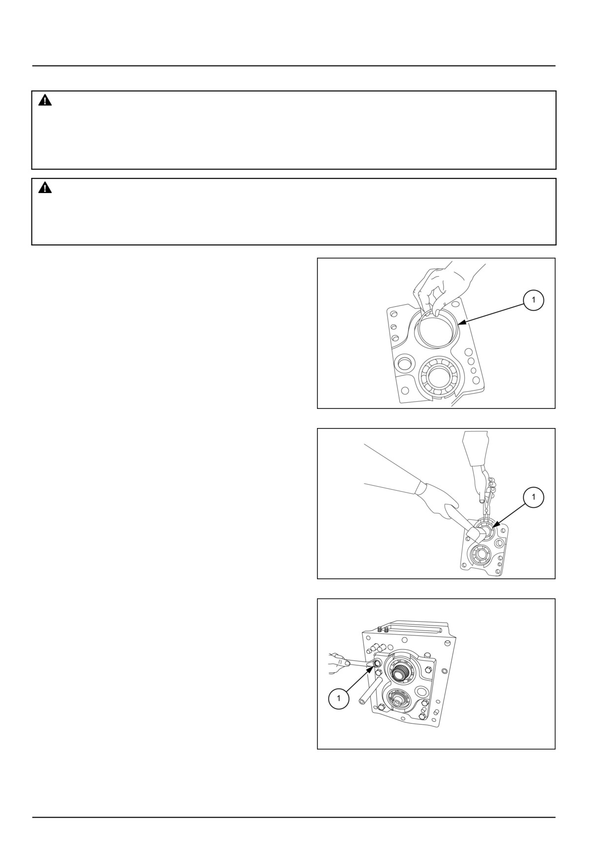
1. Install the retaining rings (1) into the intermediate plate.
GNIL14TR04141AB
1
2. Expand the retaining ring (1) and insert the bearing.
Use a hammer to drive the bearing in until the retaining
ring locks into the groove on the bearing.
3. Install the intermediate plate on the front of the trans-
mission housing.
GNIL14TR04142AB
2
4. Secure the intermediate plate with the bolts (1) that
were removed during disassembly.
GNIL14TR04143AB
3
21.1 [21.114] / 22
Transmission - Mechanical transmission
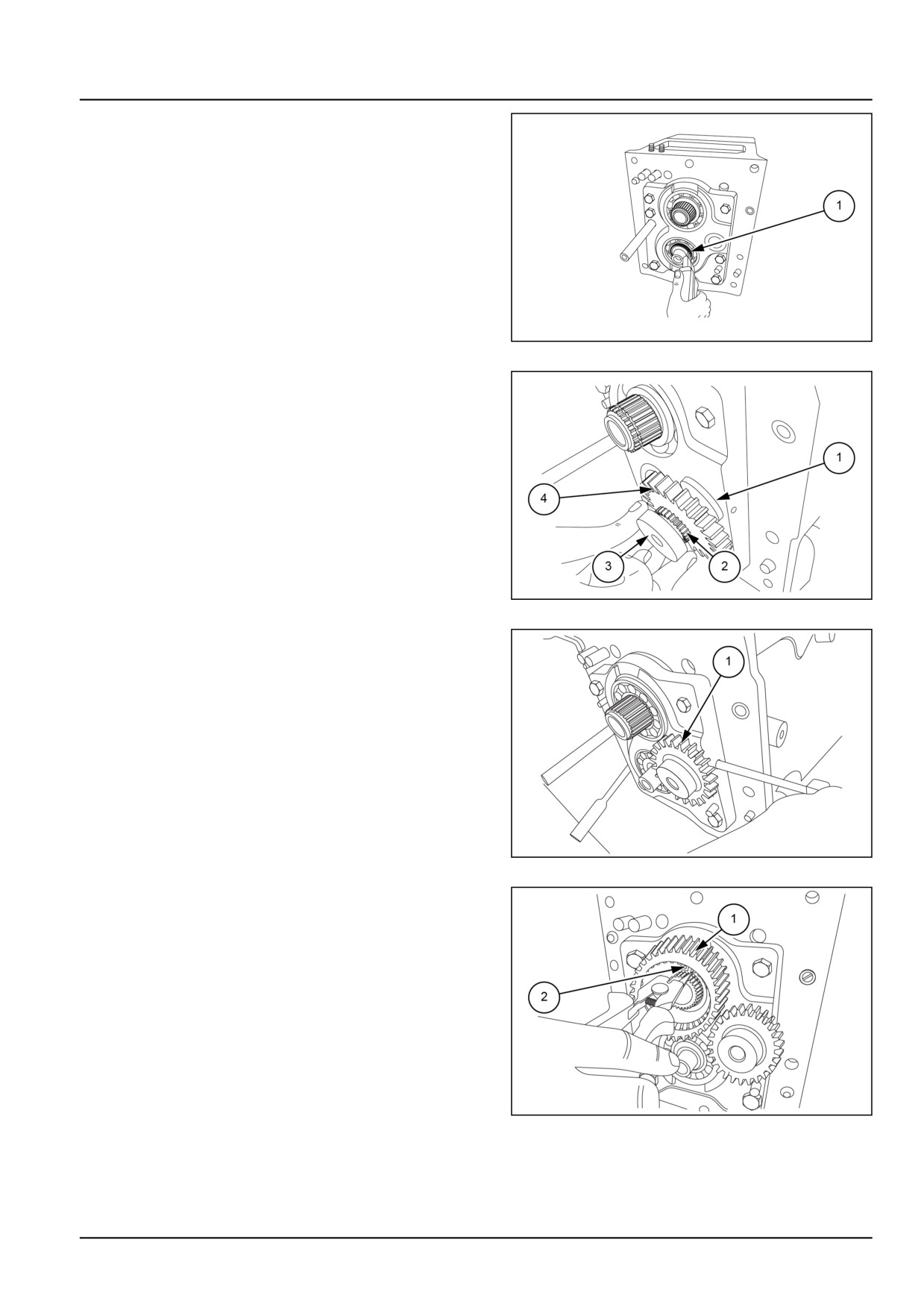
5. Secure the driven shaft bearing with the snap ring (1).
GNIL14TR04144AB
4
6. Install the spacer (1), needle bearing (2) and reverse
intermediate gear pin (3) along with the reverse inter-
mediate gear (4).
GNIL14TR04145AB
5
7. Use thread locker LOCTITE® 243™ for locking reverse
intermediate gear (1) shaft screw.
GNIL14TR04146AB
6
8. Install the reverse drive gear (1) onto the drive shaft.
9. Secure the reverse drive gear (1) with the snap ring (2).
GNIL14TR04147AB
7
21.1 [21.114] / 23
Transmission - Mechanical transmission
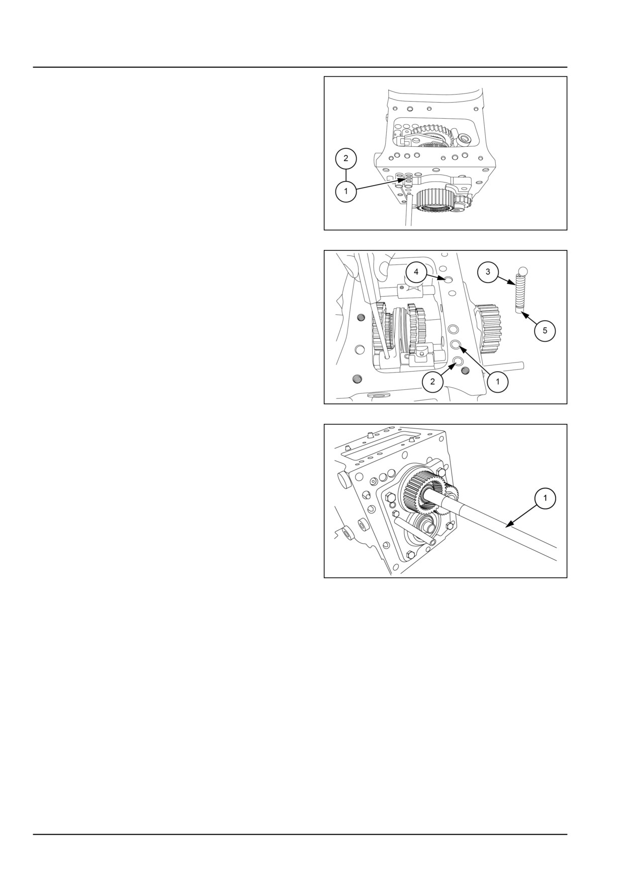
10. Install all the shift rails shift gates and shift forks after
installing the springs (1) and detent balls (2).
GNIL14TR04148AB
8
11. Install all roll pins to shift rails along with springs and
detent balls.
NOTE: Install the detent balls and springs where shown
(1) and (2). Insert the Hi/Low rail detent ball and spring (3)
where shown (4). Install the plug (5) above the Hi/Low rail
detent ball and spring at (4).
GNIL14TR04149AB
9
12. Install the Power Take-Off (PTO) shaft (1).
GNIL14TR04150AB
10
21.1 [21.114] / 24
Transmission - Mechanical transmission
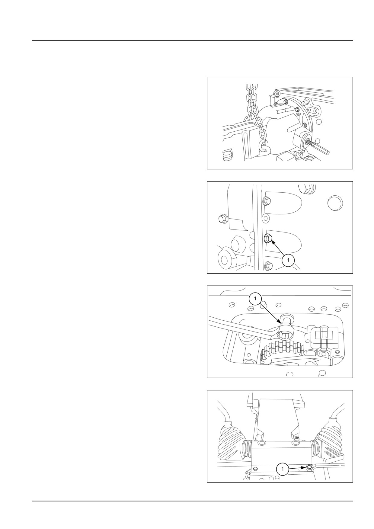
Mechanical transmission - Install
NOTE: Before assembling housings covers and support, thoroughly clean and degrease mating surfaces and apply
a 2.000 mm (0.079 in) bead of LOCTITE® 518™ sealant.
1. Use a suitable lifting device to lift and install the final
drive housing.
2. Install the final drive housing onto the transmission
housing. Secure the final drive housing with the bolts
from removal. Torque the M12 bolts to 98.00 N·m
(867.37 lb in).
3. Repeat procedure for other side.
GNIL14TR04129AA
1
4. Using a suitable lifting device, install the hydraulic
housing onto the rear of the transmission housing.
5. Remove the complete transmission assembly from the
stand using a suitable device.
6. Attach the transmission housing to the clutch housing
and secure with the M12 attaching bolts (1) from re-
moval. Torque the bolts to 88.00 N·m (778.87 lb in)
GNIL14TR04152AB
2
7. Attach the clutch housing to the transmission housing
by installing the bolt (1).
GNIL14TR04153AB
3
8. Install the M8 x 20 gear box cover bolts (1) securing
cover. Torque the bolts to 24.50 N·m (216.84 lb in).
GNIL14TR04124AB
4
21.1 [21.114] / 25
Transmission - Mechanical transmission
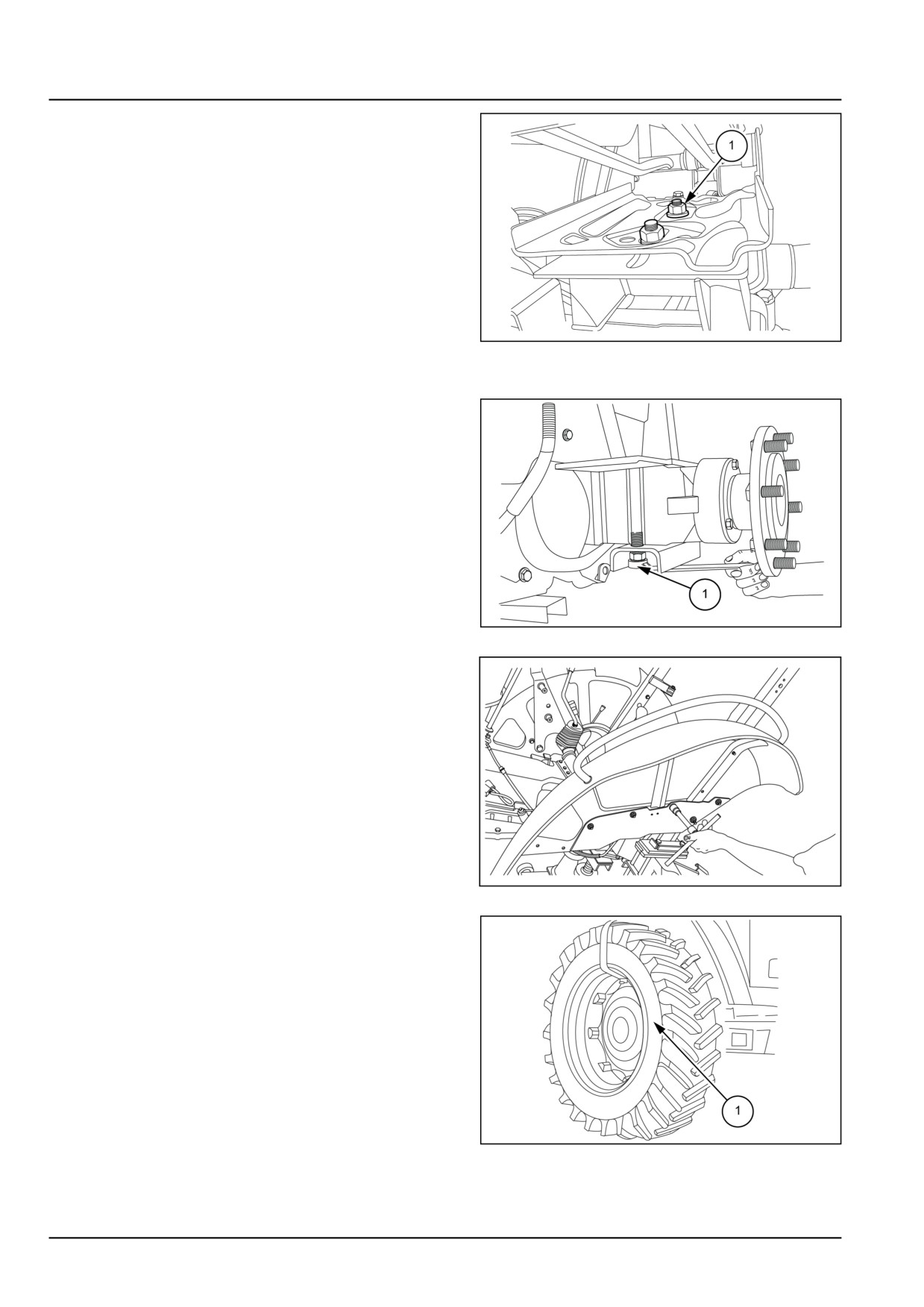
9. Install the operator's seat onto the hydraulic housing.
Connect the wiring.
GNIL14TR04021AB
5
10. Connect all the hydraulic lines.
11. Install the ROPS to the axle housings. Secure using
the bolts and nuts (1).
GNIL14TR04017AB
6
12. Install the rear fenders (1).
GNIL14TR00790AA
7
13. Install both left-hand and right-hand side wheels (1).
GNIL14TR04159AB
8
14. Remove the jack stands (1) and splitting trolley (2).
15. Install the three point linkages (1) to the tractor.
21.1 [21.114] / 26
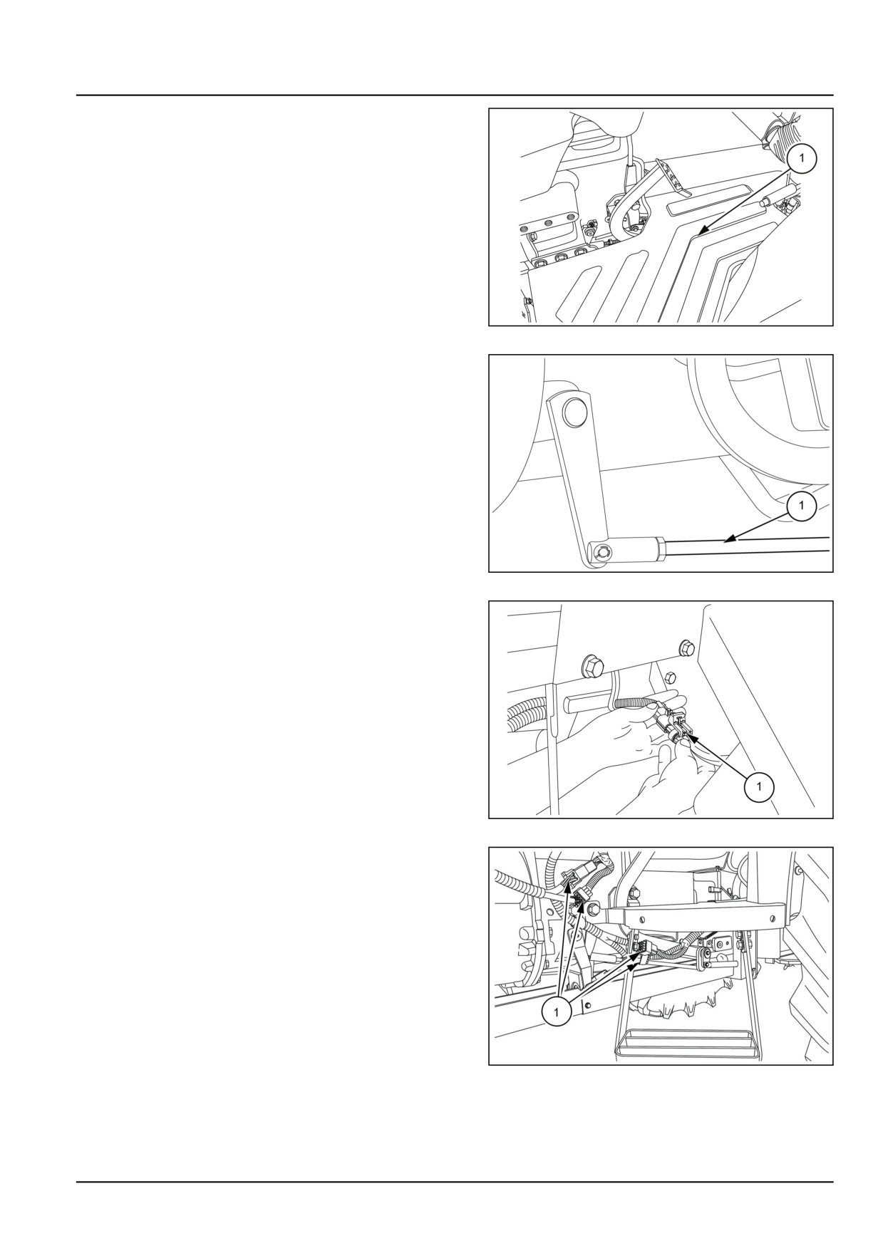
Transmission - Mechanical transmission
16. Secure the footrest (1) to the fender and transmission
housing.
GNIL14TR04162AB
9
17. Connect the clutch linkage (1).
NOTE: Check the clutch pedal free play and adjust as nec-
essary.
NOTE: Connect the brake linkage rods to the brake pedals.
GNIL14TR04164AB
10
18. Connect the wire harness connector (1) between left-
hand and right-hand side fenders.
GNIL14TR04165AB
11
19. Connect the electrical couplings (1).
GNIL14TR00797AA
12
21.1 [21.114] / 27
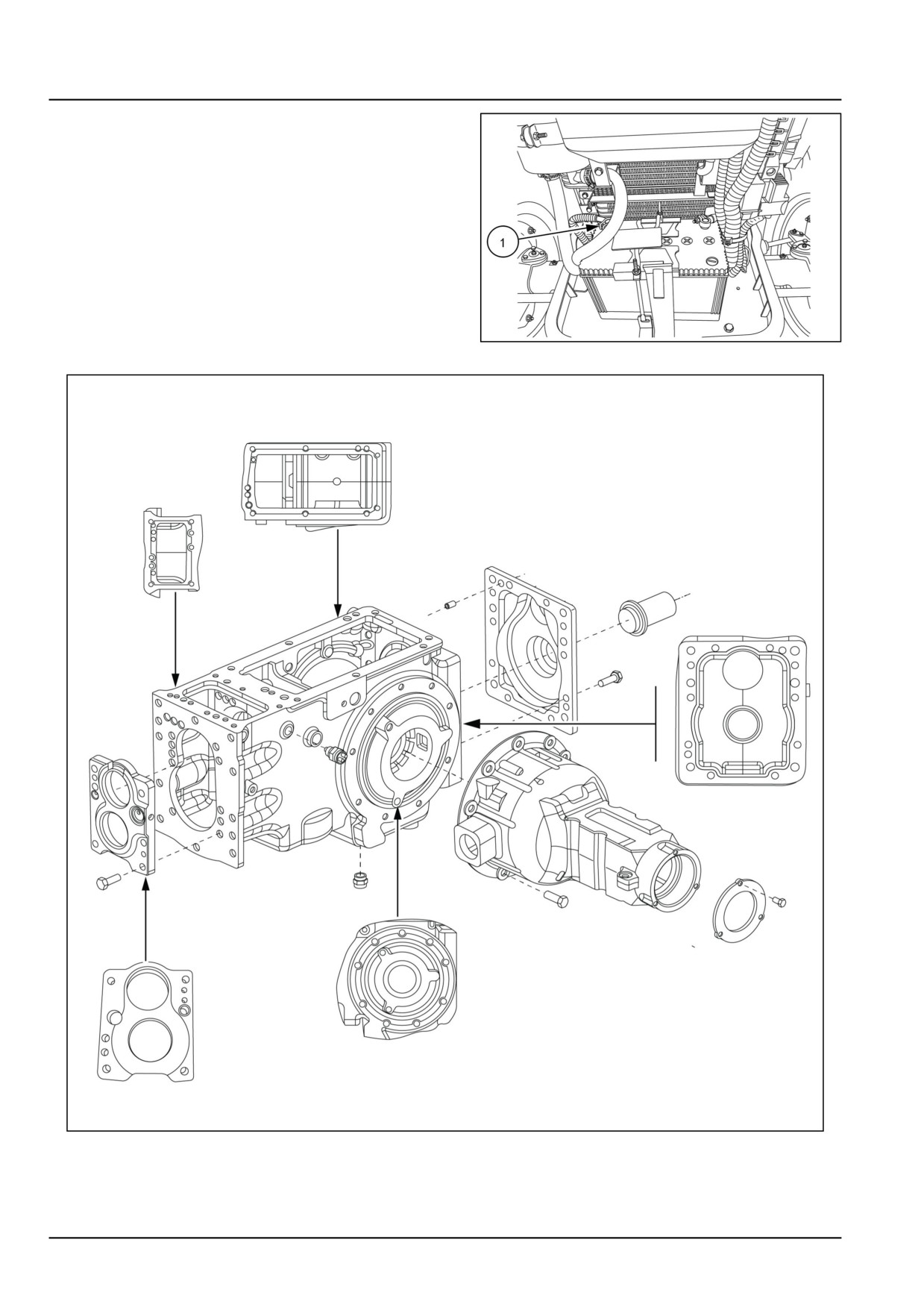
Transmission - Mechanical transmission
20. Connect the negative battery cable (1) to the negative
battery terminal.
GNIL14TR00784AA
13
GNIL14TR04168GB
14
21.1 [21.114] / 28
Transmission - Mechanical transmission
Mechanical transmission - Troubleshooting
Problem
Possible Cause
Correction
Noisy operation with
Input and output shaft support bearing mis-
Remove transmission housing and adjust
range in neutral and main
adjusted.
bearings.
lever engaged
Failed or defective inner component.
Remove housing, overhaul transmission
and replace faulty parts.
Internal component seizure due to poor lu-
Overhaul transmission and top up oil to cor-
brication.
rect level.
Noisy operation with
Faulty clutch plate springs.
Replace clutch plates.
tractor stationery, idling
engine and transmission
in neutral
Self disengagement of
External linkage and levers mis-adjusted.
Adjust correctly.
speed, range gears
Failed control rail retaining springs.
Replace springs.
Partial engagement travel.
Correct reasons for problem and restore full
travel.
Difficult engagement of
External levers mis-adjusted.
Adjust correctly.
speed and range gears
External levers stiff or seized.
Check pivot points and correct.
Internal control items
(rails, forks and
Overhaul control items.
sleeves) slide with difficulty.
21.1 [21.114] / 29
Index
Transmission - 21
Mechanical transmission - 114
Drive shaft - Service instruction
12
Mechanical transmission - Assemble - Intermediate plate
22
Mechanical transmission - Disassemble - Intermediate plate
18
Mechanical transmission - General specification
3
Mechanical transmission - Inspect - Intermediate plate
21
Mechanical transmission - Install
25
Mechanical transmission - Overview
9
Mechanical transmission - Remove
14
Mechanical transmission - Sealing
5
Mechanical transmission - Sectional view
7
Mechanical transmission - Special tools
6
Mechanical transmission - Torque
3
Mechanical transmission - Troubleshooting
29
21.1 [21.114] / 30
Transmission - 21
Mechanical transmission external controls - 130
Workmaster™ 50
Workmaster™ 60
Workmaster™ 70
21.2 [21.130] / 1
Contents
Transmission - 21
Mechanical transmission external controls - 130
SERVICE
Mechanical transmission external controls
Remove
3
Adjust
4
Transmission control levers
Disassemble
5
Install
8
21.2 [21.130] / 2
Transmission - Mechanical transmission external controls
Mechanical transmission external controls - Remove
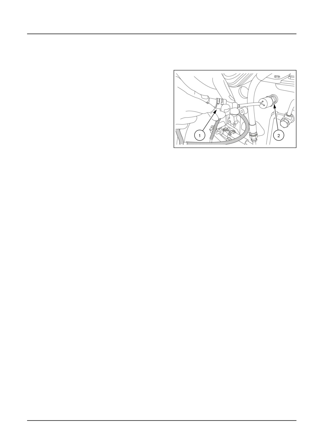
Transmission range safety switch
1. Disconnect the negative (-) battery terminal.
2. Disconnect the transmission range safety switch (1)
from the tractor wire harness.
NOTE: Switch is protected with a rubber boot.
3. Unscrew the switch (2) 1 with sealing washer from the
transmission housing.
GNIL14TR00793AA
1
21.2 [21.130] / 3
Transmission - Mechanical transmission external controls
Mechanical transmission external controls - Adjust
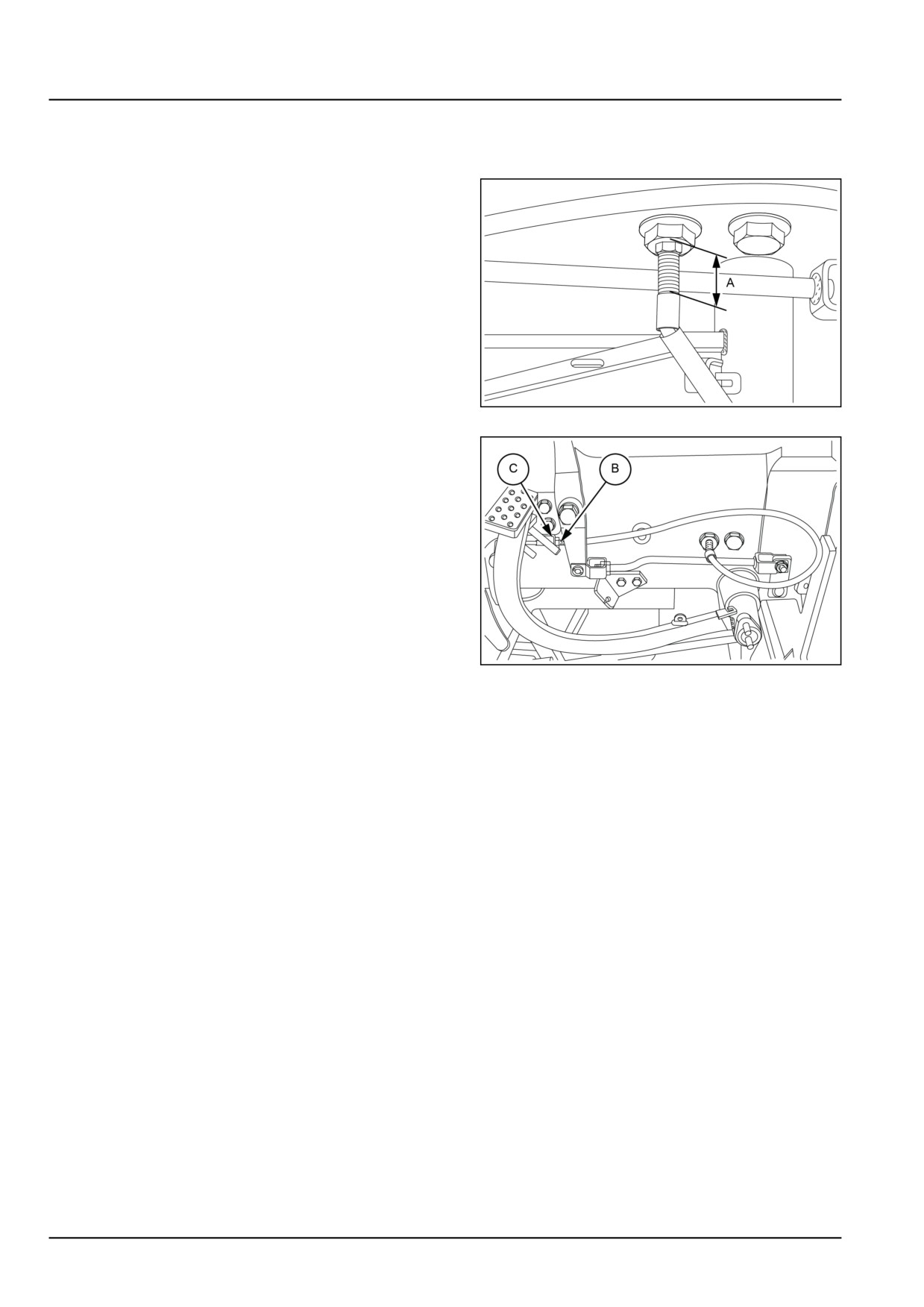
Shuttle interlock cable
1. Measure dimension (A) at cable end as shown in figure
1. (Top of nut to bottom of threads). The desired length
of (A) is approximately 26.000 mm (1.024 in), adjust if
required.
GNIL14TR04225AB
1
2. At the opposite cable end, count the number of visible
threads (B), there should be 6 or 7. Thread length can
be changed by adjusting the nuts on either side of cable
mounting bracket (C).
3. Adjust the nuts so that the shuttle lever starts to move
when clutch pedal is depressed beyond free play 50.00
- 55.00 mm (1.97 - 2.17 in) from rest) and then tighten.
GNIL14TR04226AB
2
21.2 [21.130] / 4
Transmission - Mechanical transmission external controls
Transmission control levers - Disassemble
WARNING
Avoid injury!
Handle all parts carefully. Do not place your hands or fingers between parts. Use Personal Protec-
tive Equipment (PPE) as indicated in this manual, including protective goggles, gloves, and safety
footwear.
Failure to comply could result in death or serious injury.
W0208A
CAUTION
Pinch hazard!
Always use suitable tools to align mating parts. DO NOT use your hand or fingers.
Failure to comply could result in minor or moderate injury.
C0044A
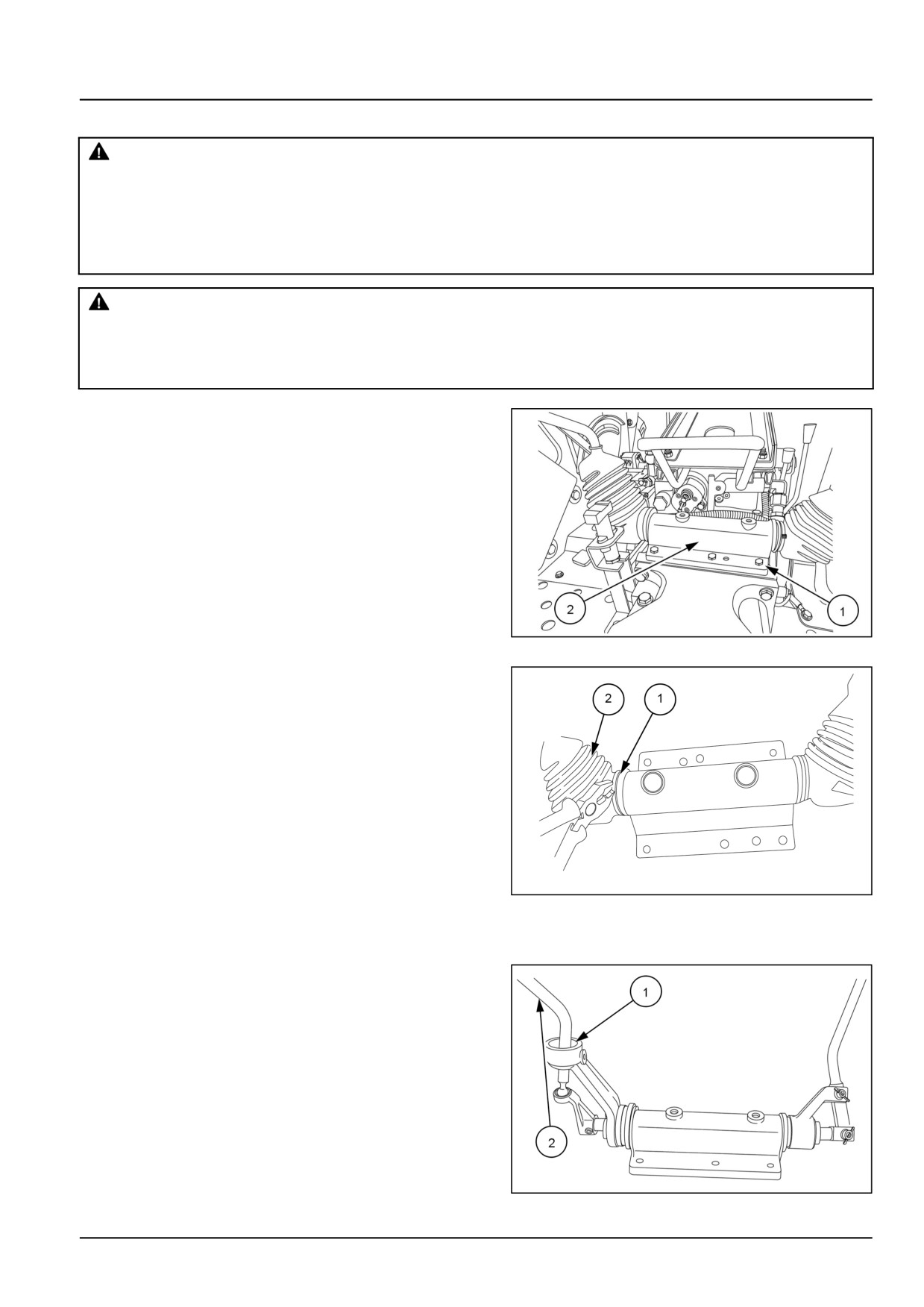
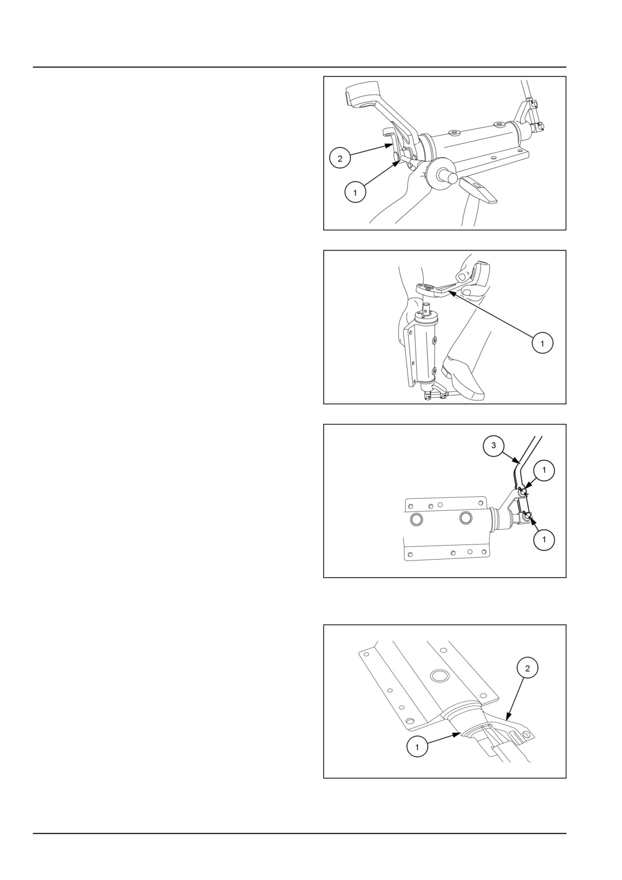
1. Loosen the bolts (1) and remove the top cover (2) from
the transmission housing.
GNIL14TR00804AA
1
2. Remove the circlip (1). Remove the gear lever rubber
boot (2).
GNIL14TR04091AB
2
Main gear selector lever
3. Remove the circlip (1) on the transmission main lever.
Remove the transmission main gear selector lever (2).
GNIL14TR00805AA
3
21.2 [21.130] / 5
Transmission - Mechanical transmission external controls
4. Remove the roll pin (1) and remove the linkage (2).
GNIL14TR00807AA
4
5. Loosen the bolt and remove the yoke (1).
GNIL14TR00809AA
5
6. Remove the split pins (1) and take out pin (2) to remove
range gear selector lever (3).
GNIL14TR04092AB
6
Range gear selector lever
7. Remove the circlip lock (1) from the yoke (2).
GNIL14TR04093AB
7
21.2 [21.130] / 6
Transmission - Mechanical transmission external controls
8. Remove the washer (1) and linkage (2).
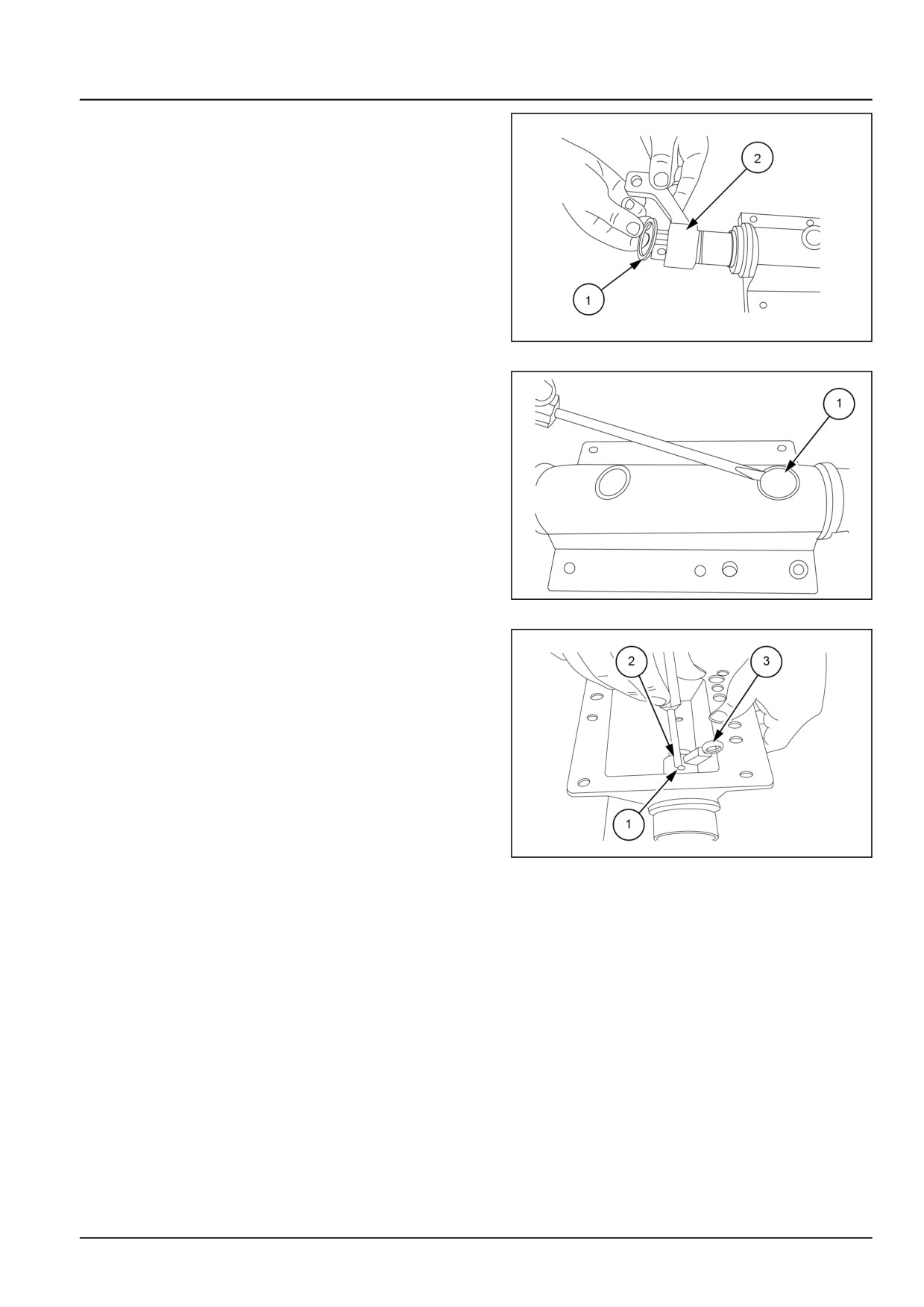
NOTE: Take out springs 2 numbers from the range lever.
GNIL14TR04094AB
8
9. Remove the expansion plug (1) from the shifter cover
housing as shown.
GNIL14TR04095AB
9
10. Remove the roll pin (1) from the shaft (2). Remove the
fork (3).
GNIL14TR04096AB
10
21.2 [21.130] / 7
Transmission - Mechanical transmission external controls
Transmission control levers - Install
Assemble the levers in the cover plate and reinstall the
cover plate on the transmission housing. Observe the
following.
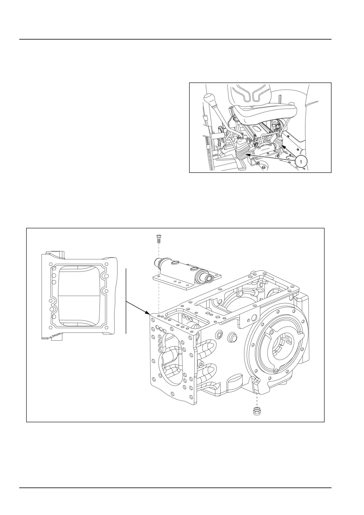
1. Inspect the rubber boot (1) for cracks or damage, re-
place if necessary.
2. Reinstallation follows the removal procedure in re-
verse, from step 7 back to step 1.
GNIL14TR00785AA
1
3. Before fixing cover plate, thoroughly clean and
degrease mating surface and apply a
2.000 mm
(0.079 in) bead of sealant following the pattern shown
in 2
4. Torque the bolts to the correct value.
GNIL14TR04099FB
2
21.2 [21.130] / 8
Index
Transmission - 21
Mechanical transmission external controls - 130
Mechanical transmission external controls - Adjust
4
Mechanical transmission external controls - Remove
3
Transmission control levers - Disassemble
5
Transmission control levers - Install
8
21.2 [21.130] / 9
Transmission - 21
Mechanical transmission internal components - 140
Workmaster™ 50
Workmaster™ 60
Workmaster™ 70
21.3 [21.140] / 1
Contents
Transmission - 21
Mechanical transmission internal components - 140
SERVICE
Transmission internal parts
Install Transmission rails and fork
3
21.3 [21.140] / 2
Transmission - Mechanical transmission internal components
Transmission internal parts - Install Transmission rails and fork
To install the shift rail and shift forks follow the proce-
dure as mentioned below.
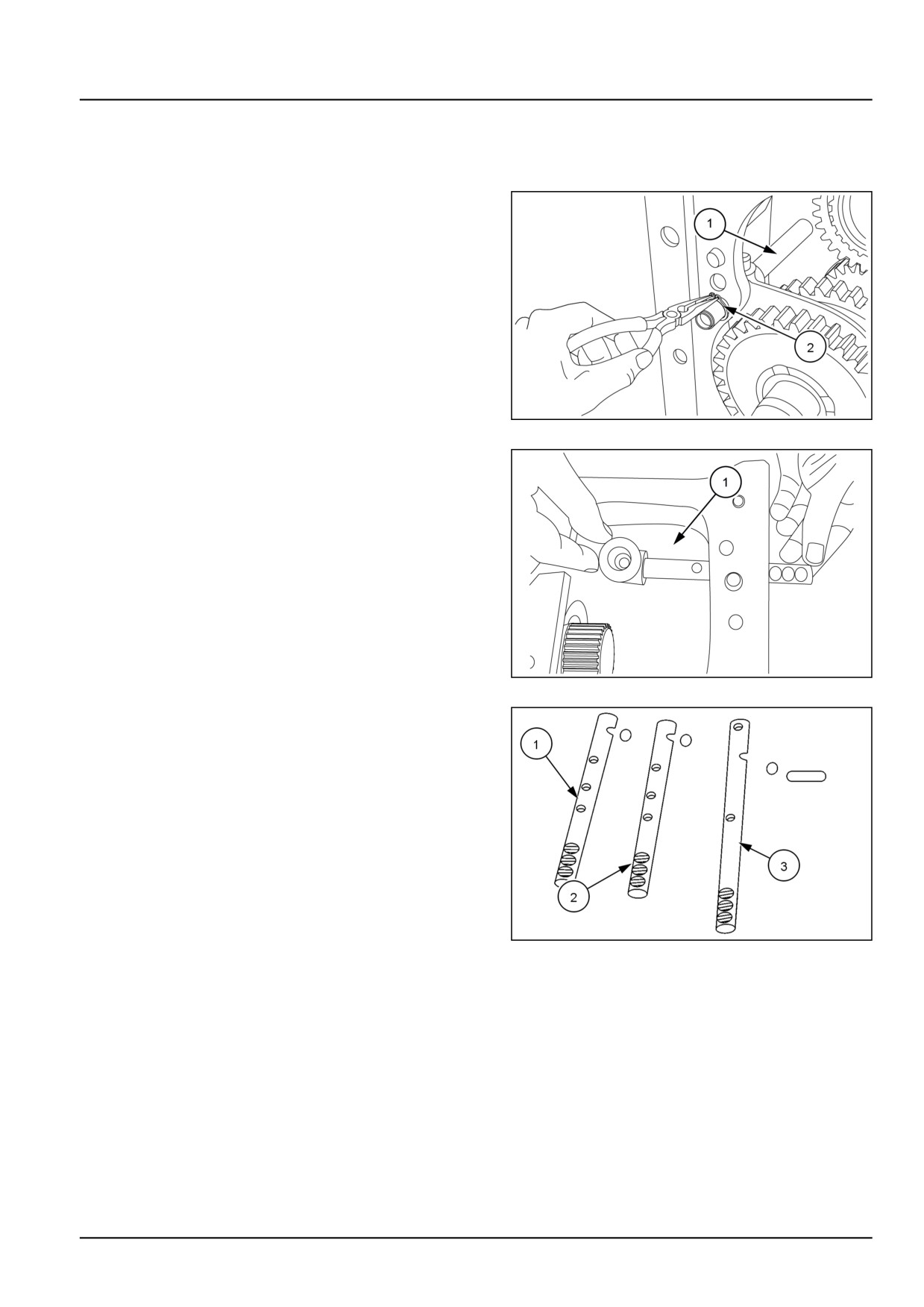
1. Insert the bottom shift rail, (1), and 1st/2nd gearshift
fork. Insert the snap ring, (2), on the bottom shift rail
and ensure it sits on the seat in housing.
GNIL14TR04227AB
1
2. The Hi/low shift rail, (1), shift fork, and shift gate should
be installed after the pinion and crown settings.
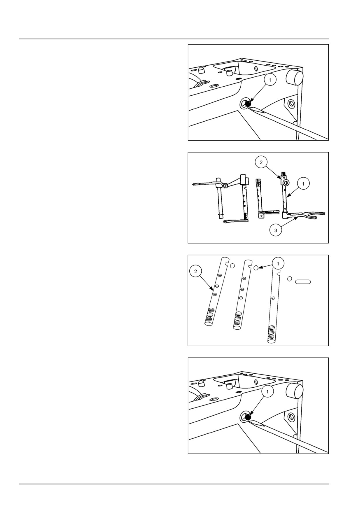
NOTE: Keep grooves of rails upward to make easy fitment
of balls and springs.
GNIL14TR04228AB
2
3. Transmission shift rails can be identified by referring to
Figure 3.To fit rails 1st/2nd (1) and 3rd/4th (2) rails are
similar. After fitting range shaft and drive shaft fit fork
for 3rd/4th and insert reverse rail (3), passing through
fork of 3rd/4th gear.
200900174
3
21.3 [21.140] / 3
Transmission - Mechanical transmission internal components
4. After fitting reverse rail insert ball (1), applying some
grease in the housing.
20097886
4
5. Insert the rail (1), of 3rd/4th with gate (2), passing
through fork (3), of 3rd/4th gear as shown in 5.
Insert gate of 1st/2nd rail shaft on the notch of 1st/2nd
gear fork.
200900175
5
6. Insert the ball (1), applying some grease in housing
after removing bolt as shown in 4.
7. Insert the 1st/2nd rail (2), passing thru gate as shown
in 5.
NOTE: Keep grooves of rails upward to make easy fitment
of balls and springs.
200900174
6
8. Insert the ball and pin (1), after removing neutral safety
switch for Hi/Lo rail then fit neutral safety switch and
tighten it.
20097886
7
21.3 [21.140] / 4
Transmission - Mechanical transmission internal components
9. After fitting reverse rail insert ball (1), applying some
grease in the housing as such it sits in groove given on
reverse rail.
10. Insert the balls (1) and springs (2) of the rails. Insert
plug above the spring of Hi/Lo rail. Fit roll pins (3), in
all rails and gates.
20099991
8
21.3 [21.140] / 5
Index
Transmission - 21
Mechanical transmission internal components - 140
Transmission internal parts - Install Transmission rails and fork
3
21.3 [21.140] / 6
Transmission - 21
Gearbox internal components - 145
Workmaster™ 50
Workmaster™ 60
Workmaster™ 70
21.4 [21.145] / 1
Contents
Transmission - 21
Gearbox internal components - 145
SERVICE
Gearbox internal components
Remove
3
Inspect
7
Install
8
Drive shaft
Remove
14
Disassemble
17
Inspect
18
Driven shaft
Remove
19
Disassemble
21
Inspect
22
Install Transmission drive and driven shafts
23
21.4 [21.145] / 2
Transmission - Gearbox internal components
Gearbox internal components - Remove
Transmission synchronizer kit and cluster gear
1. Remove the split pins to release the link.
2. Remove the circlip lock (1).
GNIL14TR04196AB
1
3. Remove the shuttle wire (1) as shown.
GNIL14TR04197AB
2
4. Collect the spring and the pin (1) as shown.
GNIL14TR04198AB
3
21.4 [21.145] / 3
Transmission - Gearbox internal components
5. Remove the shuttle detent bolt from the left-hand side
of the clutch housing.
GNIL14TR04199AB
4
6. Remove the spring (1) from the hole in the clutch hous-
ing.
GNIL14TR04200AB
5
7. Remove the detent ball (1) from the hole in the clutch
housing.
GNIL14TR04201AB
6
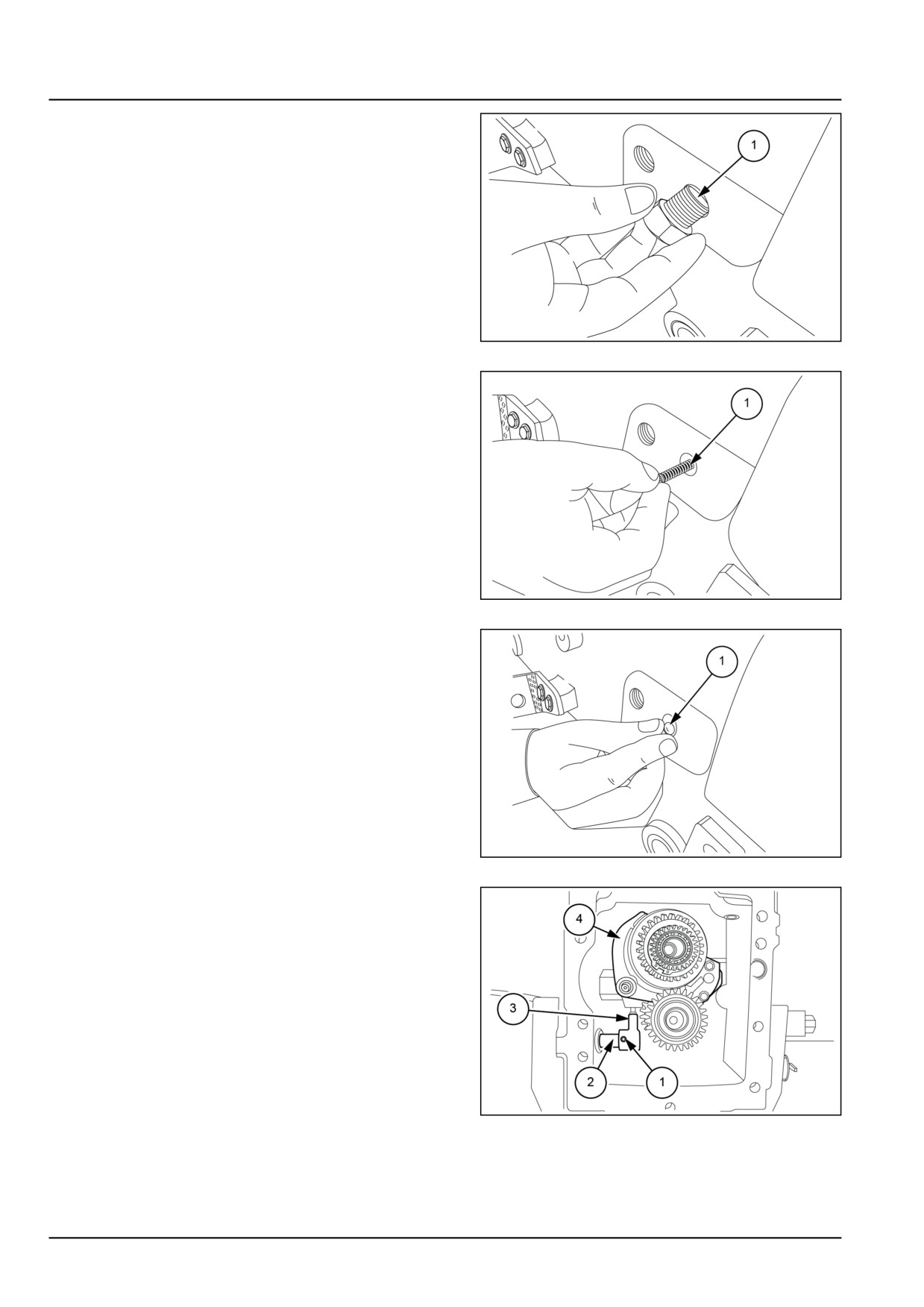
8. Remove the roll pin (1) aligning the shaft link rod (2)
and lever link rod (3).
9. Slide the shaft link rod (2) out from the lever link rod
(3) and remove the shaft link rod (2) from the cluster
housing.
10. Remove the lever link rod (3) from the shift fork (4).
11. Remove the O-rings from the shaft link rod (2).
GNIL14TR04202AB
7
21.4 [21.145] / 4