New Holland Tractor Workmaster 50 / Workmaster 60 / Workmaster 70 / Tier 4B (final). SERVICE MANUAL - page 7
Front axle system - Final drive hub, steering knuckles, and shafts
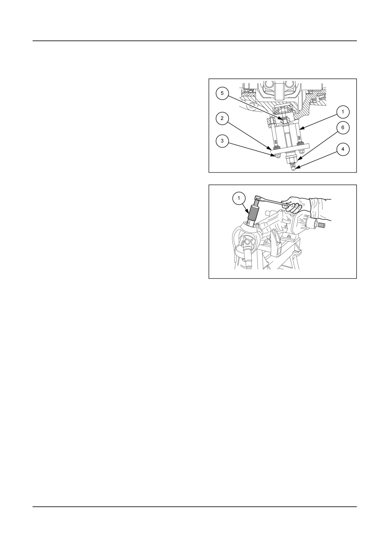
Steering knuckle and king pin - Remove
In the event that the steering knuckle pins prove difficult
to remove, proceed as follows.
1. Remove the grease nipples and the steering knuckle
pin retaining bolts.
2. Install the bolts (1) using tool number 380000265.
3. Install the plate (2) from the tool and retain it to the three
bolts with nuts (3).
4. Install the central tie bolt (4) screwing it fully into the
grease nipple bore on the pin (5).
5. Screw in the nut (6) to drive the pin out of its bore.
GNIL14TR04428AB
1
6. Using extractor tool, tool number 380000234 (1), re-
move the steering knuckle bearings.
GNIL14TR04429AB
2
NOTE: Re-install the steering knuckle bearings using a suitable drift.
25.3 [25.108] / 3
Front axle system - Final drive hub, steering knuckles, and shafts
Steering knuckle and king pin - Adjust (Stub Axle)
WARNING
Avoid injury!
Handle all parts carefully. Do not place your hands or fingers between parts. Use Personal Protec-
tive Equipment (PPE) as indicated in this manual, including protective goggles, gloves, and safety
footwear.
Failure to comply could result in death or serious injury.
W0208A
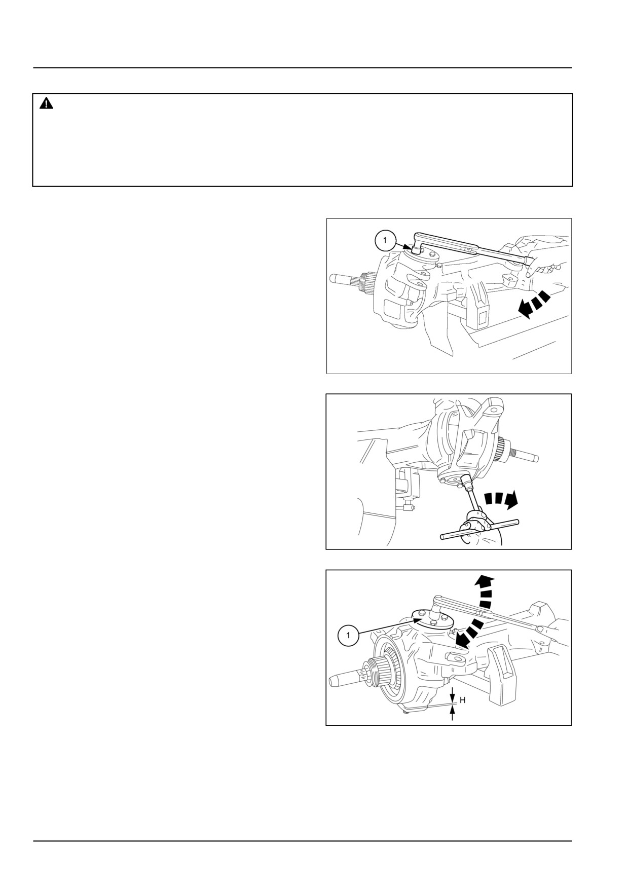
Install the front axle on a stand and proceed as follows.
1. Smear grease on the outer races of the bearings and fit
the upper cover, without the adjustment plate, but with
tool number 380000235 (1). Tighten the retaining bolts
to a torque value of 64 N·m (47 lb ft).
GNIL14TR04412AB
1
2. Install the lower cover without adjustment plate, lubri-
cate the three retaining bolts with oil.
3. Gradually tighten the lower cover bolts in sequence,
while simultaneously rotating the casing to allow the
excess grease to escape.
GNIL14TR04413AA
2
4. Using a torque wrench, tool number 380000235 (1),
check that the torque required to rotate the casing is
2.9 N·m (25.7 lb in) without considering the peak start-
ing value. If not, adjust by way of the lower cover bolts.
5. Measure the gap (H) created between the low cover
and the casing in correspondence with the three bolts.
GNIL14TR04414AB
3
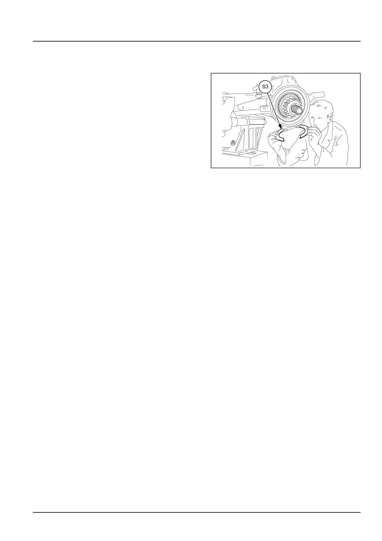
6. Calculate the average of the three values measured.
The total thickness of the adjustment shims to be fitted
under the lower cover is to be calculated as follows:
S3= H
If necessary, round up the value to the next 0.05 mm
(0.002 in).
25.3 [25.108] / 4
Front axle system - Final drive hub, steering knuckles, and shafts
7. Partially unscrew the bolts of the lower cover, insert the
shims and tighten the bolts to a torque value of 64 N·m
(47 lb ft).
8. After having rotated the casing a few times to allow
the components to bed down, check that the torque
necessary to rotate the casing is 2.9 N·m (25.7 lb in)
- 7.8 N·m (69 lb in), without considering the initial peak
torque.
9. If the torque value measured is greater than the pre-
scribed value, increase the thickness of the shims, if
the measured value is less than the prescribed value,
reduce the thickness of the shims.
10. Install the grease nipples in the upper and lower cov-
ers and grease the assembly.
GNIL14TR04415AB
4
25.3 [25.108] / 5
Front axle system - Final drive hub, steering knuckles, and shafts
Wheel hub - Adjust (4WD) - Front Axle
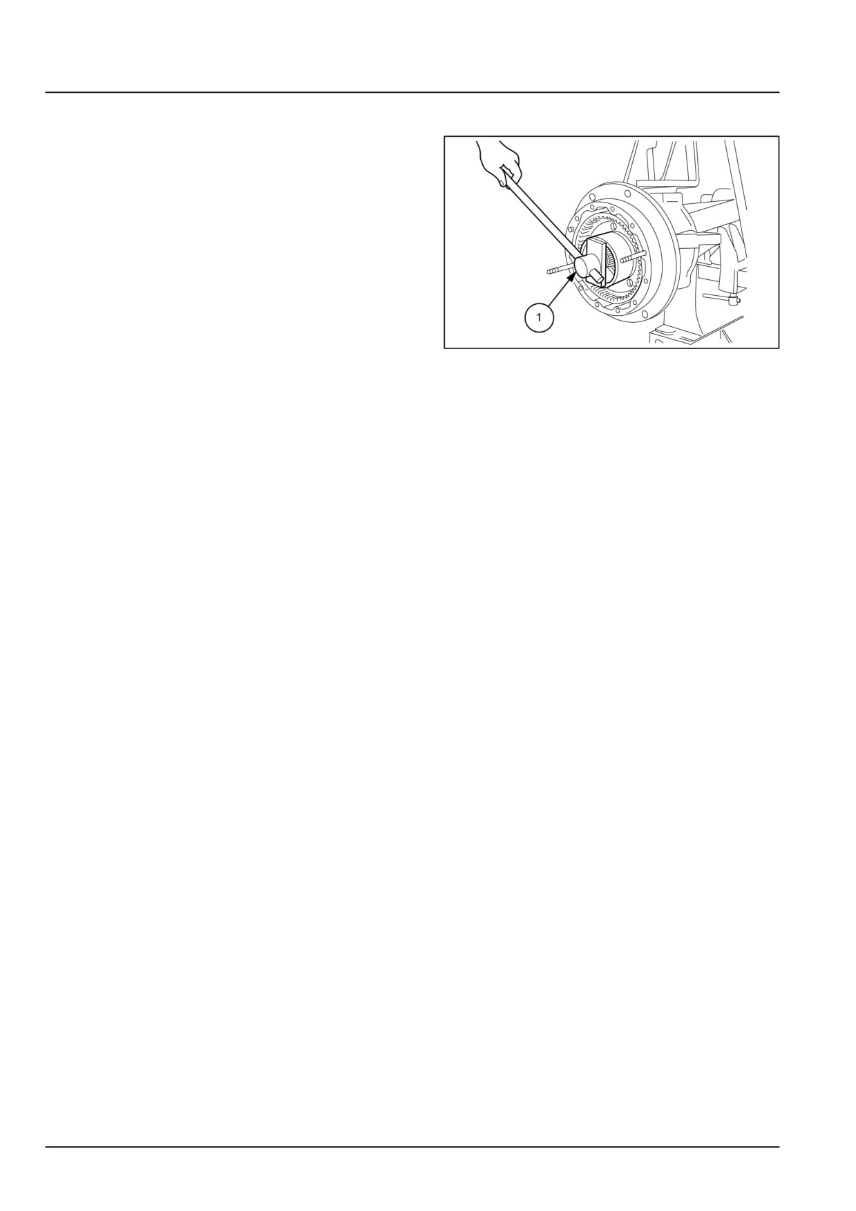
1. Proceed as follows:
• Install wheel hub and fixed gear unit onto the steer-
ing knuckle.
• Using a torque wrench and lock ring wrench, tool
number 380000295, progressively tighten the lock
ring to 147 - 196 N·m (108 - 145 lb ft). While tighten-
ing the lock ring, rotate the hub to seat the bearings.
• Fully loosen the lock ring and retighten to 392 N·m
(289 lb ft) while rotating hub.
• Secure the lock ring by bending over a lock washer
tab (if necessary, further tighten the lock ring to align
a slot with the tab).
GNIL14TR04378AB
1
• Turn the hub by hand to check for excessive play or
binding.
25.3 [25.108] / 6
Index
Front axle system - 25
Final drive hub, steering knuckles, and shafts - 108
Steering knuckle and king pin - Adjust (Stub Axle)
4
Steering knuckle and king pin - Remove
3
Wheel hub - Adjust (4WD) - Front Axle
6
25.3 [25.108] / 7
Front axle system - 25
Final drives - 310
Workmaster™ 50
Workmaster™ 60
Workmaster™ 70
25.4 [25.310] / 1
Contents
Front axle system - 25
Final drives - 310
SERVICE
Final drive driving pinion
Preload - (4WD) Front Axle
3
Adjust - (4WD) Front Axle
5
25.4 [25.310] / 2
Front axle system - Final drives
Final drive driving pinion - Preload - (4WD) Front Axle
WARNING
Avoid injury!
Handle all parts carefully. Do not place your hands or fingers between parts. Use Personal Protec-
tive Equipment (PPE) as indicated in this manual, including protective goggles, gloves, and safety
footwear.
Failure to comply could result in death or serious injury.
W0208A
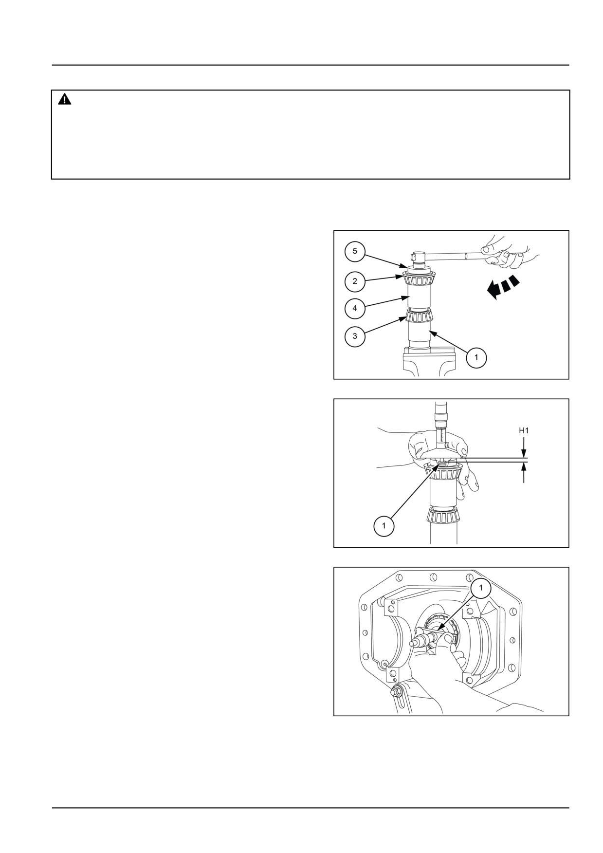
Adjustment of the preload of the pinion shaft bearings
Proceed as follows:
1. Clamp tool number 380000248 (1) in the vice. Install
bearings (2), (3) and the bearing spacer (4) and tighten
the nut of the tool fully home.
NOTE: Install the 10 mm (0.394 in) thick spacer between
tool number 380000248 (1) and the bearing (2).
GNIL14TR04419AB
1
2. Using a micrometer, measure distance
(H1) be-
tween the upper surface and the pin of tool number
380000248
(1).
3. Disassemble the above parts, lubricate the bearings
with oil and then re-assemble the parts, excluding the
bearing spacer, in the bevel drive-differential housing,
complete with outer bearing races, held in place with
tool number 380000255.
GNIL14TR04420AB
2
4. Tighten the nut of tool number 380000255 (1), while
turning the tool to ensure that the bearings are seated
correctly.
5. Using a micrometer, measure the distance (H2) be-
tween the upper surface and the pin of the tool.
6. The thickness of the adjustment shim required is given
by:
Shim = H2 - H1 + 0.05 mm (0.002 in)
GNIL14TR04421AB
3
25.4 [25.310] / 3
Front axle system - Final drives
If necessary, round the value thus obtained up to the
nearest 0.05 mm (0.002 in).
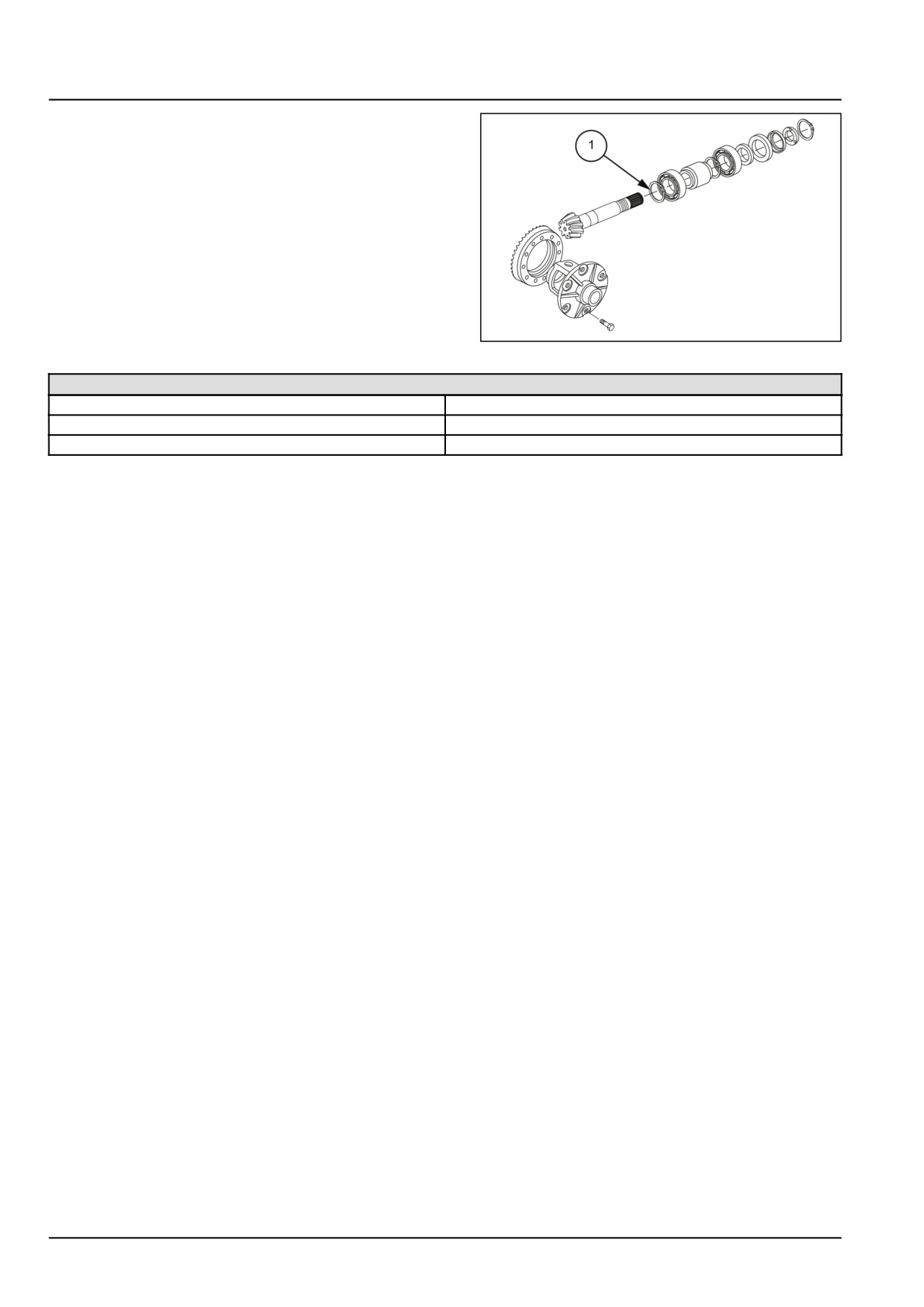
Pinion positioning shim (1) is located between pinion
gear and front bearing.
NOTE: On completing the adjustment, do not remove the
adjustment tool from the bevel drive-differential housing:
leave in place for adjustment of the drive pinion position.
GNIL14TR04422AB
4
Available shim sizes
0.5 mm (0.020 in)
2.7 mm (0.106 in)
2.5 mm (0.098 in)
2.8 mm (0.110 in)
2.6 mm (0.102 in)
2.9 mm (0.114 in)
25.4 [25.310] / 4
Front axle system - Final drives
Final drive driving pinion - Adjust - (4WD) Front Axle
Determining the thickness of the drive pinion position adjustment shim
Proceed as follows.
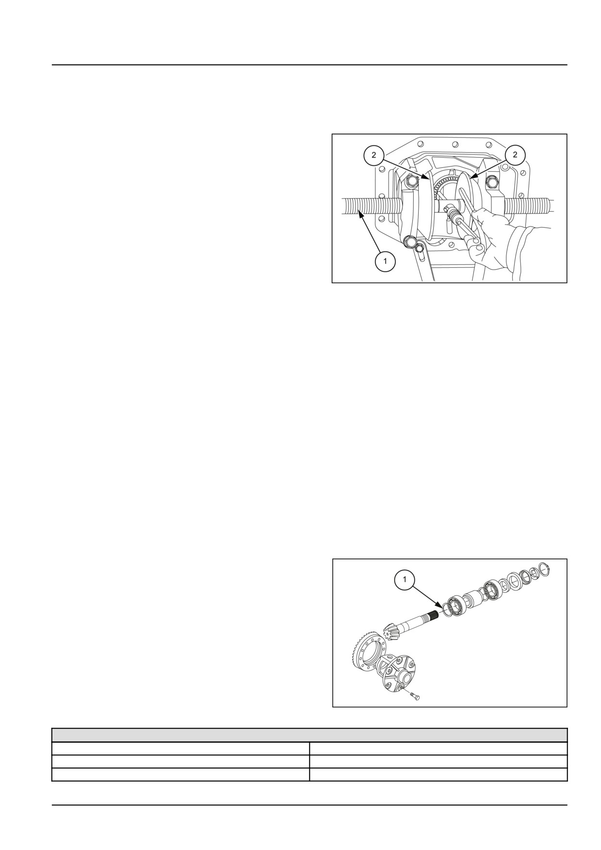
1.
Install tool number 380000249 (1) in the bevel drive-
differential housing complete with outer bearing rings,
ring gear bearings adjustment ring, ring gear bearings
adjustment shim, circlip and differential support caps.
2.
Screw the cones (2) of tool number 380000249 (1) in or
out in order to orientate the micrometer shaft inline with
the inner bearing ring while eliminating the end play
between the cones and the outer rings of the ring gear
bearings.
3.
Adjust the micrometer so that the shaft is in contact with
inner bearing race and measure the distance (H3) thus
obtained.
GNIL14TR04423AB
1
4.
Determine the correct distance (H5) between the ring
gear axis and the large diameter base of the pinion:
H5 =H4 ± C
where:
H4 = 95 mm (3.74 in) nominal distance between the
ring gear axis and the large diameter base of the pinion.
C= correction value stamped on pinion preceded by a +
or - sign, (if other than 0), to be added to or subtracted
from the nominal distance (H4) according to the sign.
5.
The thickness of the adjustment shim will be given by:
Shim = H3 - H5
where:
H3 = the distance measured using the micrometer.
H5 = corrected nominal distance between the crown
wheel axis and the large diameter base of the pinion.
6.
Remove tool number 380000248 and tool number
380000249 from bevel drive housing.
7.
Install the drive pinion complete with: inner bearing
races, spacer and adjustment shims of the previously
determined thickness.
Pinion bearing preload shim (1) is located between
spacer and rear bearing.
GNIL14TR04424AB
2
Available shim sizes
0.5 mm (0.020 in)
2.75 mm (0.108 in)
2.5 mm (0.098 in)
2.8 mm (0.110 in)
2.55 mm (0.100 in)
2.85 mm (0.112 in)
25.4 [25.310] / 5
Front axle system - Final drives
Available shim sizes
2.6 mm (0.102 in)
2.9 mm (0.114 in)
2.65 mm (0.104 in)
2.95 mm (0.116 in)
2.7 mm (0.106 in)
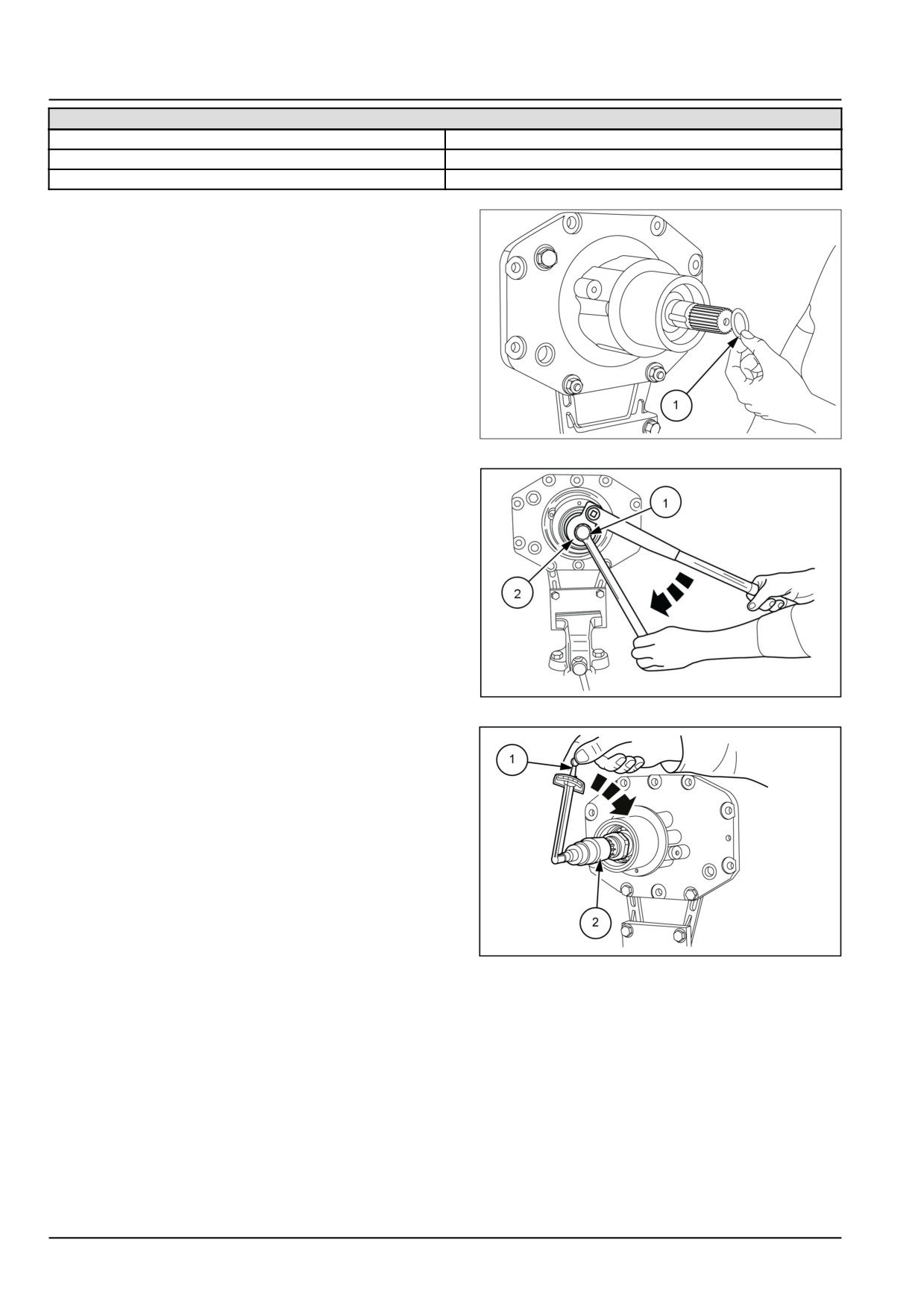
8. Install the O-ring seal (1) on the drive pinion shaft.
9. Then insert the spacer and then the detent ball, after
having carefully lubricated the outer surface.
GNIL14TR04425AB
3
10.
Install the pinion lock tool, tool number 380000257 (1).
11.
Install wrench, tool number
380000268
on the
threaded adjustment ring.
12.
Using a wrench on the pinion lock tool (1), hold the
pinion against rotation, and using a torque wrench po-
sitioned exactly as shown in the figure on the threaded
adjustment ring wrench (2), tighten the adjustment
ring to a torque value of 294 N·m (217 lb ft) while si-
multaneously rotating the pinion shaft to ensure that
the bearings are seated correctly.
GNIL14TR04430AB
4
13.
With a torque wrench (1) on the pinion lock tool, tool
number 380000257 (2), check that the pinion rolling
torque, without oil seal and relative dust seal ring is
0 N·m (0 lb in) - 0.2 N·m (1.8 lb in).
If the rolling torque is less than the prescribed value,
install a thinner adjustment shim shown in Figure 2, if
the torque is greater than the prescribed value, install
a thicker adjustment shim.
14.
Unscrew the threaded adjustment ring and install the
oil seal and the dust seal ring. Tighten the threaded
ring to a torque of 294 N·m (217 lb ft), while simul-
taneously rotating the pinion shaft to ensure that the
bearings are seated correctly.
GNIL14TR04355AB
5
15.
With a inch/pound torque wrench (1) on the pinion
lock tool number 380000257 (2), check that the pinion
rolling torque with the oil seal and relative dust seal
ring is 0.5 N·m (4.4 lb in) - 1 N·m (9 lb in).
Finally, carefully stake the threaded ring and fit the
circlip on the drive pinion shaft.
25.4 [25.310] / 6
Index
Front axle system - 25
Final drives - 310
Final drive driving pinion - Adjust - (4WD) Front Axle
5
Final drive driving pinion - Preload - (4WD) Front Axle
3
25.4 [25.310] / 7
25.4 [25.310] / 8
Front axle system - 25
Non-powered front axle - 400
Workmaster™ 50
Workmaster™ 60
Workmaster™ 70
25.5 [25.400] / 1
Contents
Front axle system - 25
Non-powered front axle - 400
TECHNICAL DATA
Non-powered front axle
General specification
3
Torque
3
Special tools
4
Sealing
4
FUNCTIONAL DATA
Non-powered front axle
Overview
5
Sectional view
6
SERVICE
Non-powered front axle
Remove
8
Install
10
Front axle
Remove - Spindle Assembly
11
Overhaul - Spindle Assembly
13
Install - Spindle assembly
14
Axle wheel hub
Remove
15
Install
17
DIAGNOSTIC
Non-powered front axle
Troubleshooting
18
25.5 [25.400] / 2
Front axle system - Non-powered front axle
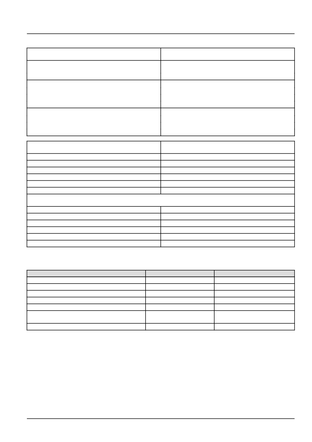
Non-powered front axle - General specification
Centrally pivoted U-type centre beam without telescopic
Type
outer section
2 ° corresponding to approx. 15.00 mm (0.59 in) with
Wheel camber
406.40 mm (16.00 in) rims
Wheel toe-in
0.000 - 5.000 mm (0.000 - 0.197 in)
Swivel pin assembly
Swivel pin (3) diameter at the bushes
29.967 mm (1.180 in) / 30.000 mm (1.181 in)
Press-fit bush (4) inner diameter
30.140 mm (1.187 in) / 30.060 mm (1.183 in)
Swivel pin to bush clearance
0.060 - 0.173 mm (0.002 - 0.007 in)
Axle pivot pin assembly
Pivot pin (9) diameter
29.967 mm (1.180 in) / 30.000 mm (1.181 in)
Press-fit bush (4) inner diameter
30.140 mm (1.187 in) / 30.060 mm (1.183 in)
Pivot pin to bush clearance
0.060 - 0.173 mm (0.002 - 0.007 in)
2WD
7.50 - 16
Dished In
AC
1424.0 mm (56.1 in)
BD
1524.0 mm (60.0 in)
CE
1624.0 mm (63.9 in)
DF
1724.0 mm (67.9 in)
EG
1824.0 mm (71.8 in)
FH
1924.0 mm (75.7 in)
2WD
Dished Out
AC
1472.0 mm (58.0 in)
BD
1572.0 mm (61.9 in)
CE
1672.0 mm (65.8 in)
DF
1772.0 mm (69.8 in)
EG
1872.0 mm (73.7 in)
FH
1972.0 mm (77.6 in)
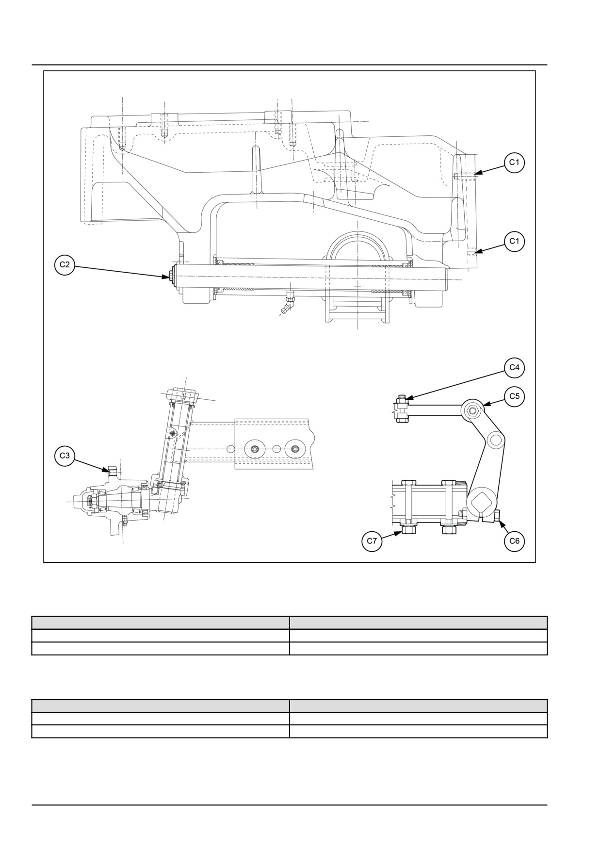
Non-powered front axle - Torque
Description
Thread size
Torque
Bolt, front axle carrier to engine (C1)
M16 x 2
22.00 kgf (48.50 lbf)
Bolt, axle pivot (C2)
M10 x 1.25
6.00 kgf (13.23 lbf)
Bolt, wheel to hub (C3)
M14 x 1.5
15.00 kgf (33.07 lbf)
Nut, track/drag link, ball joint (C4)
M10 x 1
2.50 kgf (5.51 lbf)
Nut, track/ drag link, ball joint (C5)
M14 x 1.5
10.00 kgf (22.05 lbf)
Nut, right-hand side and left-hand side control
M12 x 1.25
9.00 kgf (19.84 lbf)
lever (C6)
Axle extension securing bolts (C7)
M16 x 1.5
11.80 kgf (26.01 lbf)
25.5 [25.400] / 3
Front axle system - Non-powered front axle
GNIL14TR04431GB
1
Non-powered front axle - Special tools
Tool description
Tool number
Slide hammer for centre pin
380001545
Adapter for slide hammer
290793
Non-powered front axle - Sealing
Operation description
Specification
Front wheel hub sleeve
LOCTITE® 638™
King pin thrust washer
LOCTITE® 638™
25.5 [25.400] / 4
Front axle system - Non-powered front axle
Non-powered front axle - Overview
The adjustable front axle is composed of a reversed U-type centre beam with telescopic sections at each end.
A number of holes at 50.00 mm (2.00 in) intervals are provided in the telescopic sections for track width adjustment
purpose. Adjustment of the front wheel track width is affected by extending or retracting both ends of the axle equally.
The centre beam is attached to the front axle carrier by means of a single pivot which allows oscillation on both sides.
The front axle is controlled by mechanical steering through swivel pin control lever. The two swivel pins are connected
by telescopic track control rod, which contain adjustment for toe-in.
25.5 [25.400] / 5
Front axle system - Non-powered front axle
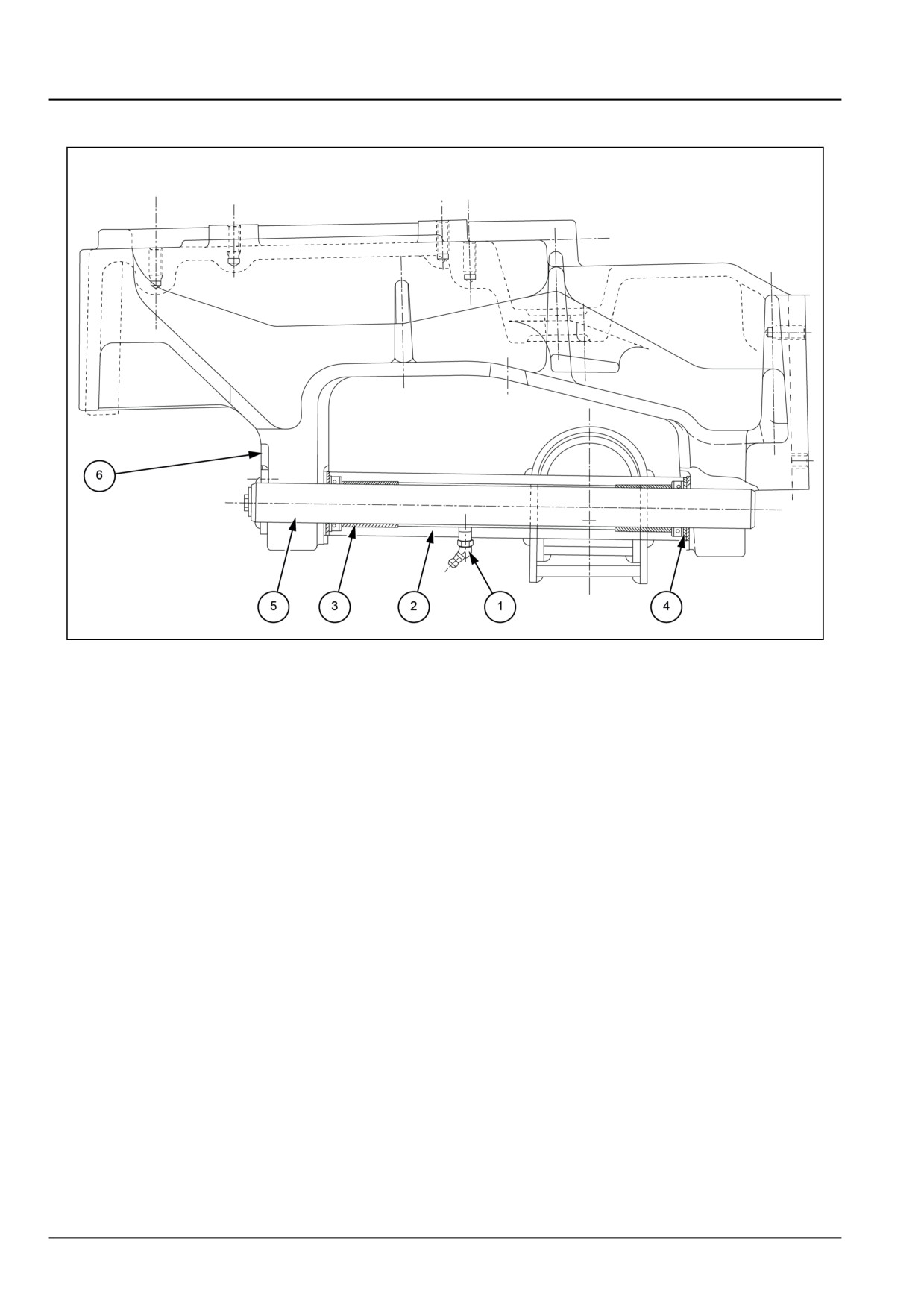
Non-powered front axle - Sectional view
GNIL14TR04432FB
1
Front axle support
1.
Grease fitting
4.
Thrust washers
2.
Axle centre beam
5.
Axle pivot pin
3.
Axle pivot pin bushings
6.
Front axle carrier
25.5 [25.400] / 6
Front axle system - Non-powered front axle
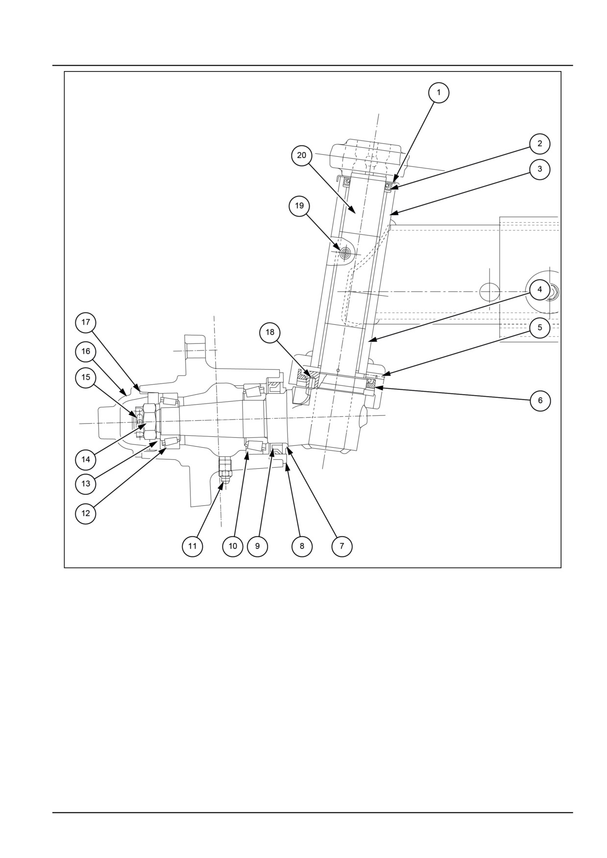
GNIL14TR04433GB
2
Stub assembly
1.
Dust cover
11. Grease nipple
2.
Oil seal
12. Bearing
3.
Bush upper
13. Thrust washer
4.
Bush lower
14. Castle nut
5.
Thrust washer
15. Split pin
6.
Seal
16. Dust cover
7.
Dust cover
17. O-ring
8.
Bush (sleeve)
18. Thrust washer pin
9.
Seal
19. Grease nipple
10. Bearing
20. King pin
25.5 [25.400] / 7
Front axle system - Non-powered front axle
Non-powered front axle - Remove
DANGER
Heavy objects!
Lift and handle all heavy components using lifting equipment with adequate capacity. Always support
units or parts with suitable slings or hooks. Make sure the work area is clear of all bystanders.
Failure to comply will result in death or serious injury.
D0076A
Remove the front axle assembly from the tractor as fol-
lows:
1. Open and raise front hood.
2. Disconnect the negative cable from the battery and in-
sulate.
3. Safely block rear wheels.
4. Remove front weights and weight support, where fitted.
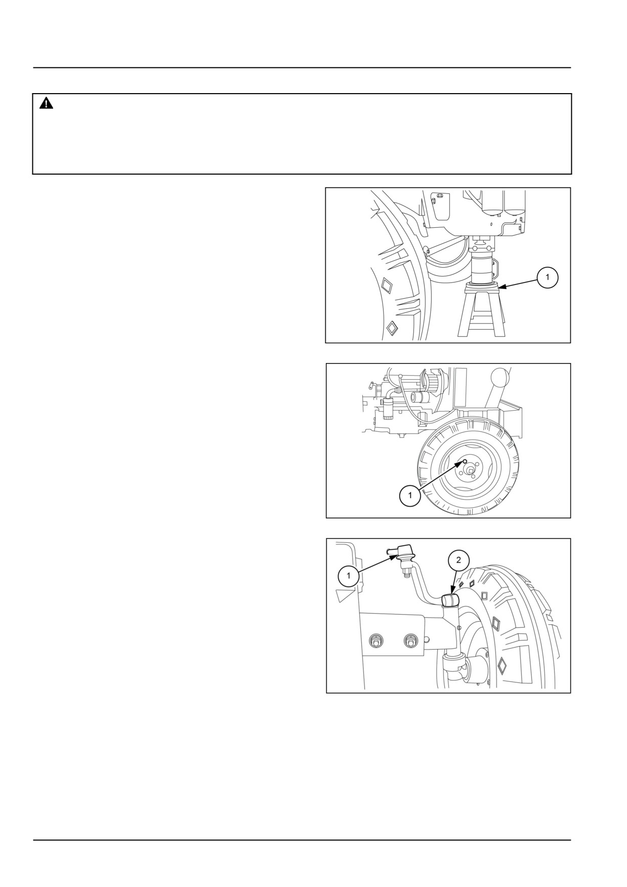
5. Jack up front tractor and place a stationary stand (1)
under the sump.
GNIL14TR04434AB
1
6. Loosen retaining bolts (1) and remove the front wheels.
GNIL14TR04435AB
2
7. Remove knuckle joint nut (1) and disconnect drag link
(2) from control lever.
GNIL14TR04436AB
3
25.5 [25.400] / 8
Front axle system - Non-powered front axle
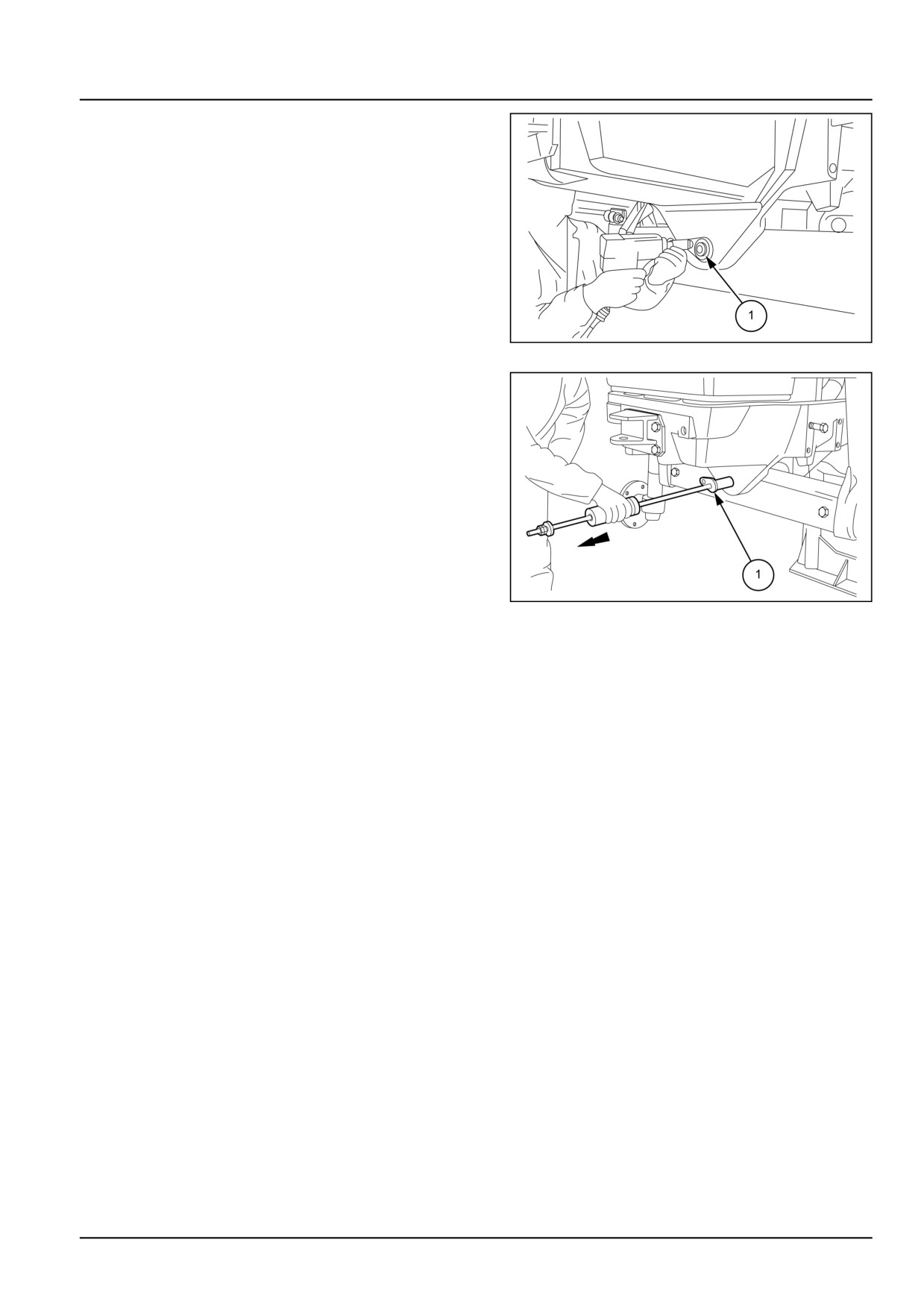
8. Remove the axle pivot pin locking bolt (1).
GNIL14TR04437AB
4
11. Using a slide puller (special tool number 292927)
with tool no. 380001545 withdraw the pivot pin (1).
10. Recover thrust washers and shims provided be-
tween axle carrier and centre beam.
11. Remove front axle from tractor using a hoist.
GNIL14TR04438AB
5
25.5 [25.400] / 9
Front axle system - Non-powered front axle
Non-powered front axle - Install
Reinstall the front axle assembly to carrier observing
the following:
1. Reassembly follows disassembly procedure in reverse,
refer to Non-powered front axle - Remove (25.400).
CAUTION
Pinch hazard!
Always use suitable tools to align mating parts.
DO NOT use your hand or fingers.
Failure to comply could result in minor or mod-
erate injury.
C0044A
2. Check the pivot pin play. It should not exceed 0.25 mm
(0.01 in). If play is more, add shims between axle car-
rier and centre beam.
3. Check for correct toe-in setting. See “front wheel set-
ting tests” for details.
4. Tighten all fasteners to correct torques.
25.5 [25.400] / 10
Front axle system - Non-powered front axle
Front axle - Remove - Spindle Assembly
WARNING
Avoid injury!
Handle all parts carefully. Do not place your hands or fingers between parts. Use Personal Protec-
tive Equipment (PPE) as indicated in this manual, including protective goggles, gloves, and safety
footwear.
Failure to comply could result in death or serious injury.
W0208A
Swivel pins can be removed and overhauled with the
front axle on the tractor proceed as follows for each
wheel:
1. Safely block rear wheels.
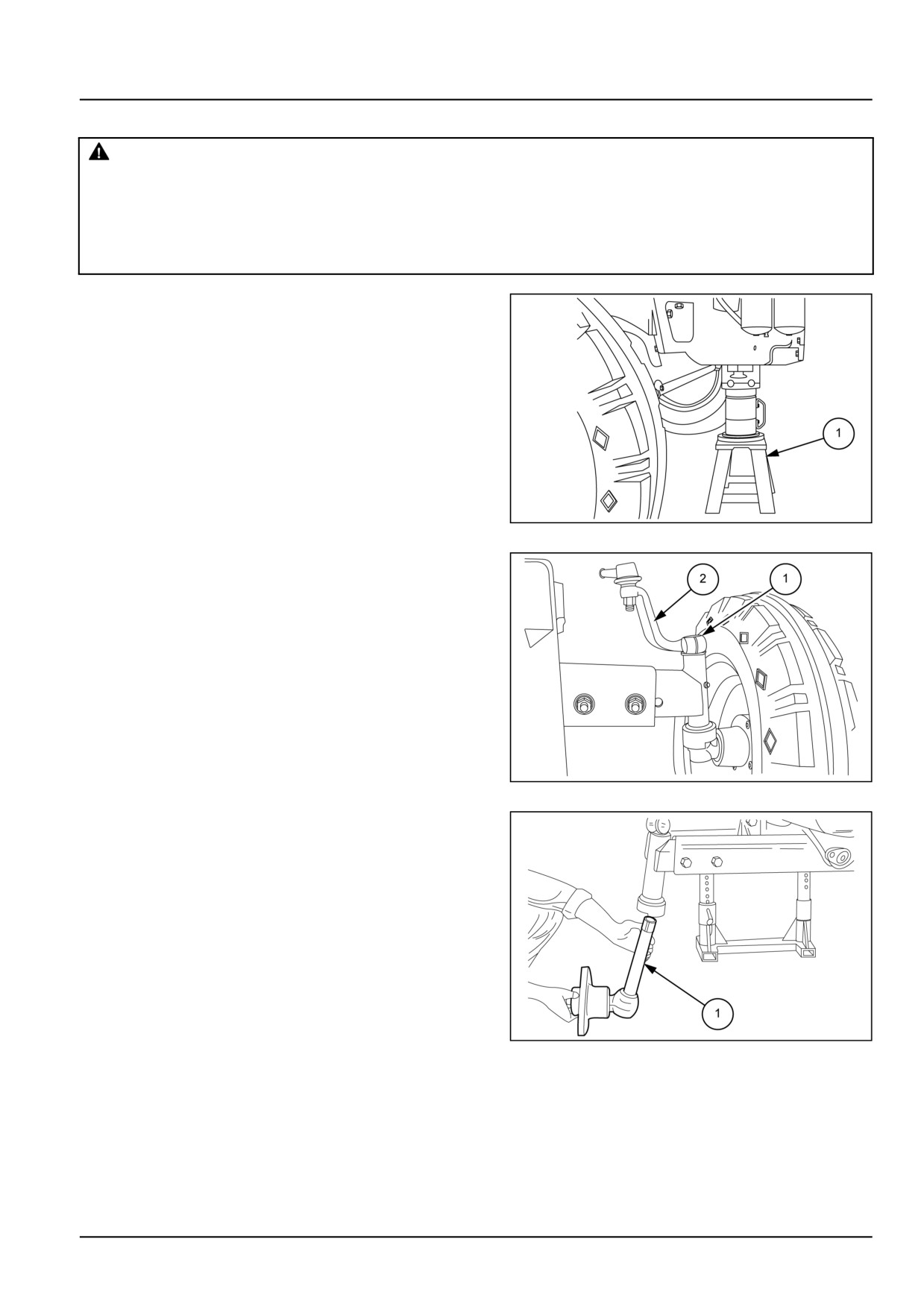
2. Jack up front tractor and place a stationary stand (1)
under the sump.
3. Loosen retaining bolts and remove front wheels.
GNIL14TR04449AB
1
4. Remove swivel pin control lever retaining bolt (1).
5. Slide out the control lever (2) from the spindle assem-
bly.
GNIL14TR04450AB
2
6. Pull out the swivel axle and hub assembly (1) from axle
outer section.
GNIL14TR04451AB
3
25.5 [25.400] / 11
Front axle system - Non-powered front axle
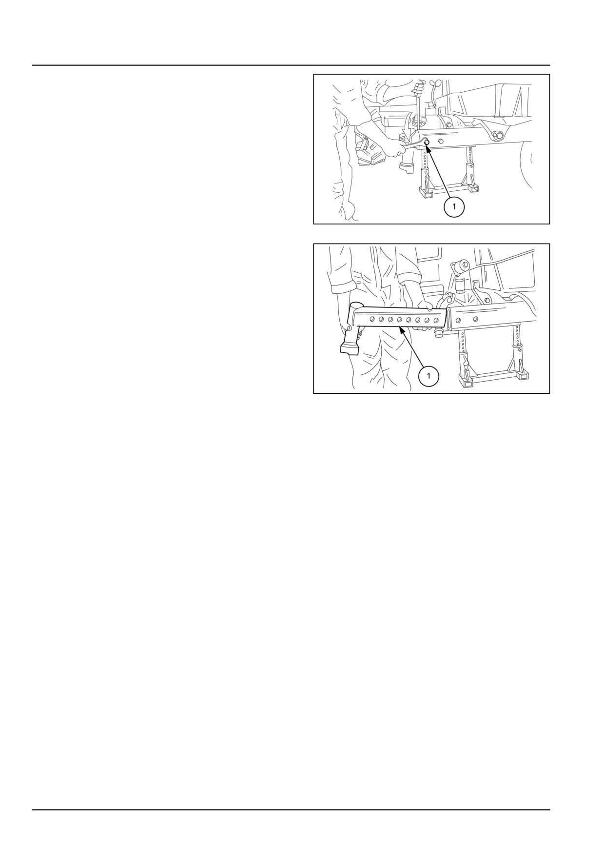
7. Remove the axle outer section (1) attaching bolts.
GNIL14TR04452AB
4
8. Remove the axle outer section (1).
GNIL14TR04453AB
5
25.5 [25.400] / 12
Front axle system - Non-powered front axle
Front axle - Overhaul - Spindle Assembly
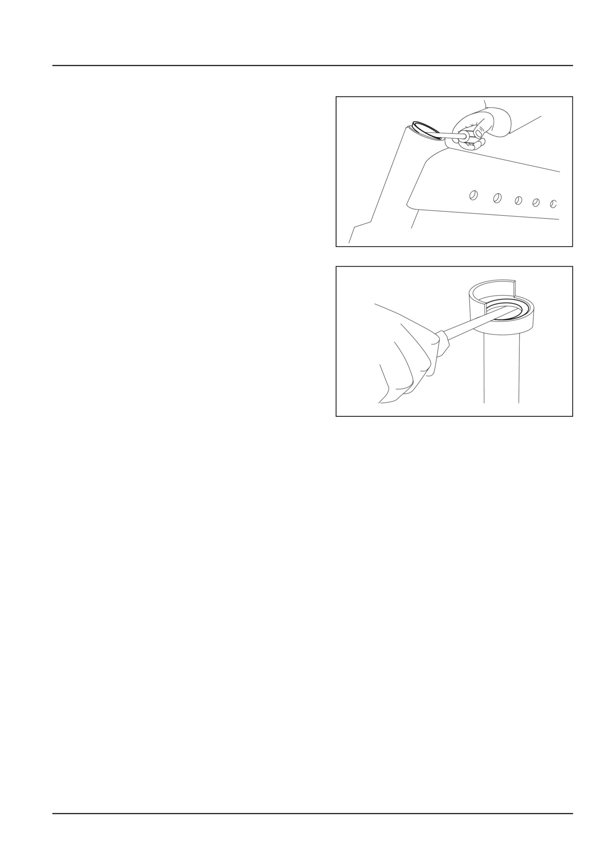
1. Fix the axle outer section in a vice and remove the
upper seal using suitable tool.
GNIL14TR04454AA
1
2. Remove the bottom seal using suitable tool and recover
thrust washer.
3. Check the swivel bearing bushes for wear. See spec-
ifications in Non-powered front axle - General spec-
ification (25.400). If bushes require replacement, re-
move the bushes using suitable tool.
4. Using a suitable drift install new bushings on the axle
outer section.
5. Check the swivel pin for wear. If required replace new
spindle.
6. Ream the new bushings to suit the swivel pin.
GNIL14TR04455AA
2
25.5 [25.400] / 13

Front axle system - Non-powered front axle
Front axle - Install - Spindle assembly
Reinstall the spindle assembly to the front axle following
the disassembly procedure in reverse.
NOTE: Make sure that the slot (1) in the thrust washer fits
on the notch provided on the axle outer section.
GNIL14TR04456AB
1
25.5 [25.400] / 14
Front axle system - Non-powered front axle
Axle wheel hub - Remove
WARNING
Avoid injury!
Handle all parts carefully. Do not place your hands or fingers between parts. Use Personal Protec-
tive Equipment (PPE) as indicated in this manual, including protective goggles, gloves, and safety
footwear.
Failure to comply could result in death or serious injury.
W0208A
Wheel hubs can be removed with the front axle on the
tractor. Proceed as follows for each hub.
1. Safely block rear wheels.
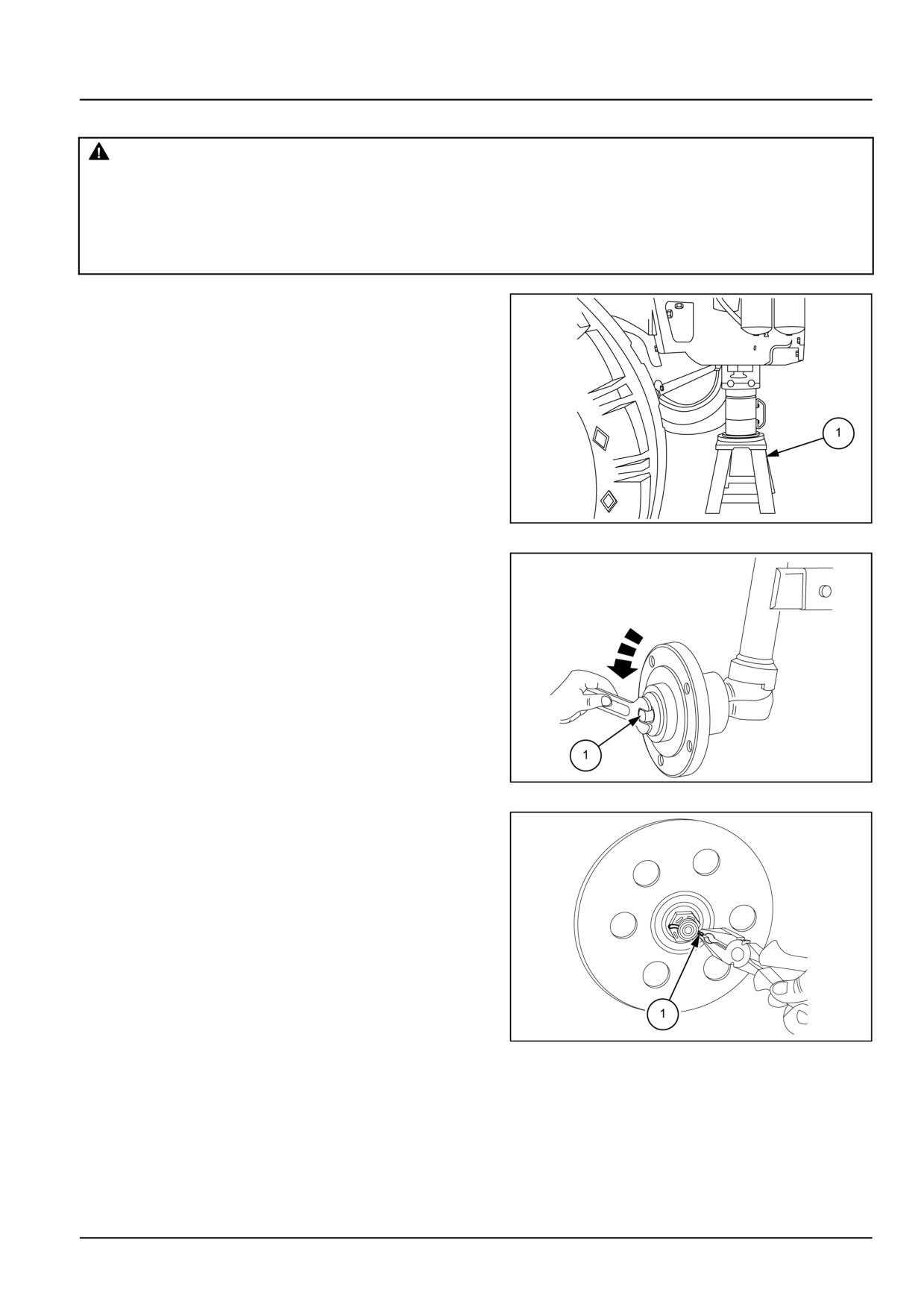
2. Jack up front tractor and place a stationary stand (1)
under the sump.
3. Loosen retaining bolts and remove front wheels.
GNIL14TR04439AB
1
4. Remove wheel hub bearing grease cup (1).
GNIL14TR04440AB
2
5. Remove split pin (1).
GNIL14TR04441AB
3
25.5 [25.400] / 15
Front axle system - Non-powered front axle
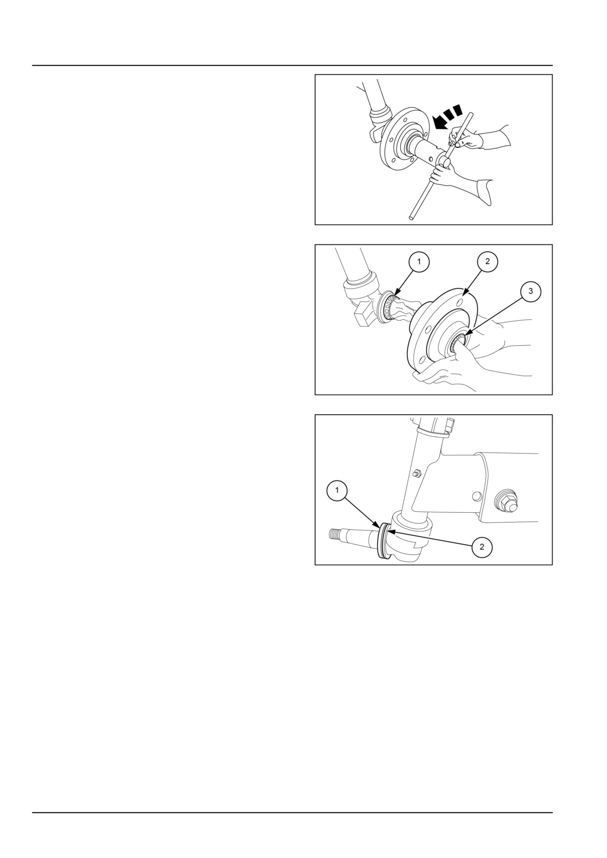
6. Using the socket spanner loosen the wheel hub bear-
ing. Adjust castle nut.
GNIL14TR04442AA
4
7. Remove wheel hub (2) and recover bearing (1) and (3).
GNIL14TR04443AB
5
8. Remove seal (1) and nyloc ring (2) using suitable tool.
GNIL14TR04444AB
6
25.5 [25.400] / 16
Front axle system - Non-powered front axle
Axle wheel hub - Install
1. Replace faulty seals and worn bearing using suitable
pullers and drifts.
2. Fill the wheel hub with specified grease.
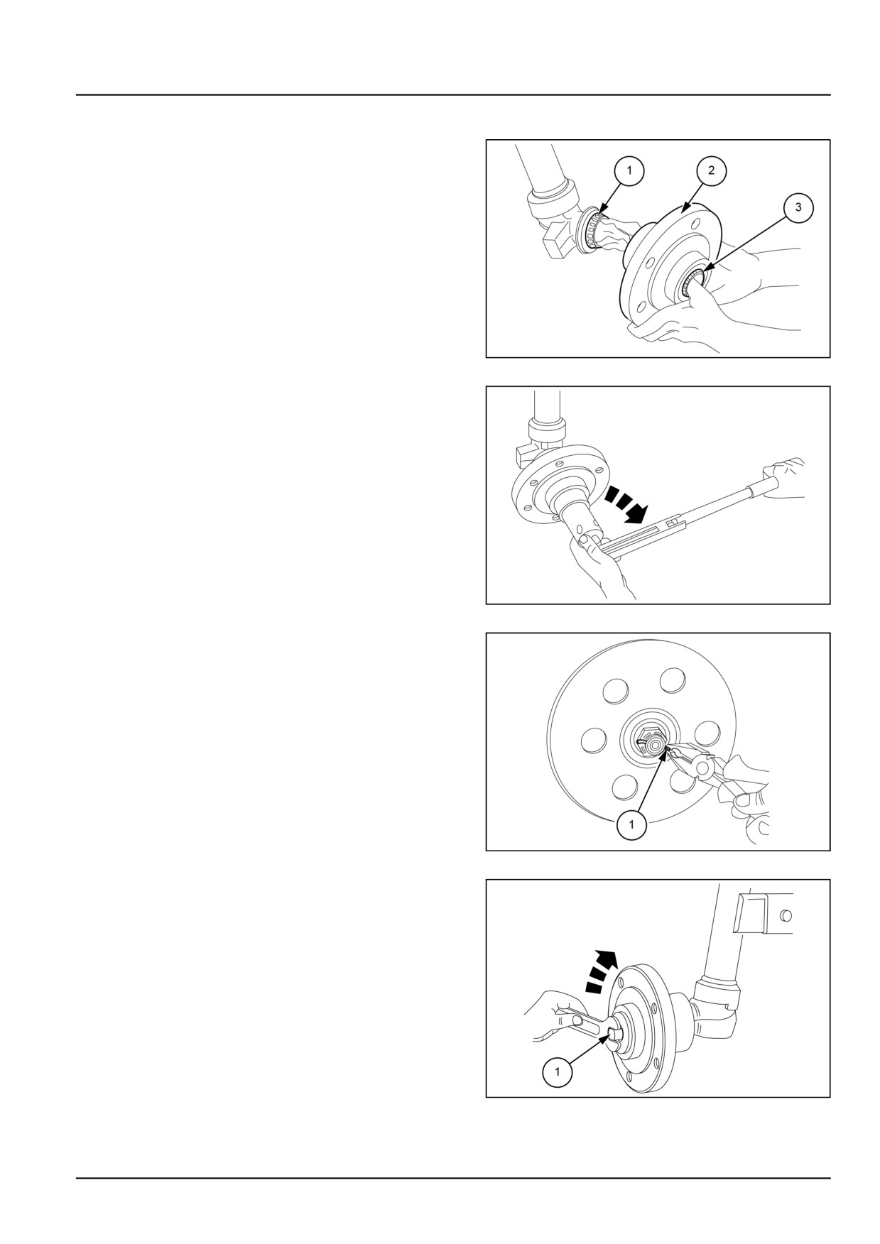
3. Re-assemble the wheel hub (2) complete with the bear-
ings (1) and (3).
GNIL14TR04445AB
1
4. Using a torque wrench and socket spanner (1) tighten
the castle nut while turning the wheel hub (1) to set-
tle the bearing. Tighten the nut until wheel hub gets
slightly tight to rotate.
5. Loosen the castle nut and torque it again to 9.8 N·m
(7.2 lb ft) continuing to turn the wheel hub.
GNIL14TR04446AA
2
6. Insert split pin (1).
GNIL14TR04447AB
3
7. Reassemble the wheel hub dust cap (1).
NOTE: Check the O-ring provided on the dust cap for any
cut or damage. If required replace the O-ring.
GNIL14TR04448AB
4
25.5 [25.400] / 17

Front axle system - Non-powered front axle
Non-powered front axle - Troubleshooting
Problem
Possible Cause
Correction
Premature tire wear
Wrong inflation pressure
Inflate tyres to correct pressure refer to val-
ues suggested in the operator’s manual.
Always comply with values specified by the
tire manufacture
Wrong front wheel toe-in
Adjust toe-in (see the procedure explained
in this section under adjustment)
Poor tractor stability
Wrong inflation pressure
Inflate tyres to correct pressure
25.5 [25.400] / 18
Index
Front axle system - 25
Non-powered front axle - 400
Axle wheel hub - Install
17
Axle wheel hub - Remove
15
Front axle - Install - Spindle assembly
14
Front axle - Overhaul - Spindle Assembly
13
Front axle - Remove - Spindle Assembly
11
Non-powered front axle - General specification
3
Non-powered front axle - Install
10
Non-powered front axle - Overview
5
Non-powered front axle - Remove
8
Non-powered front axle - Sealing
4
Non-powered front axle - Sectional view
6
Non-powered front axle - Special tools
4
Non-powered front axle - Torque
3
Non-powered front axle - Troubleshooting
18
25.5 [25.400] / 19
CNH Industrial America New Holland Site 100 Brubaker Avenue New Holland, Pennsylvania United States
17557
SERVICE - Technical Publications & Tools
PRINTED IN U.S.A.
All rights reserved. No part of the text or illustrations of this publication may be reproduced.
NEW HOLLAND policy is one of continuous improvement and the right to change prices, specification or equipment
at any time without notices is reserved.
All data given in this publication is subject to production variations. Dimensions and weight are approximate only and
the illustrations do not necessarily show products in standard condition. For exact information about any particular
product, please consult your NEW HOLLAND Dealer.
EN
SERVICE MANUAL
Rear axle system
Workmaster™ 50
Workmaster™ 60
Workmaster™ 70
27
Contents
Rear axle system - 27
[27.100] Powered rear axle
27.1
[27.106] Rear bevel gear set and differential
27.2
[27.120] Planetary and final drives
27.3
27
Rear axle system - 27
Powered rear axle - 100
Workmaster™ 50
Workmaster™ 60
Workmaster™ 70
27.1 [27.100] / 1
Contents
Rear axle system - 27
Powered rear axle - 100
FUNCTIONAL DATA
Powered rear axle
Overview
3
27.1 [27.100] / 2
Rear axle system - Powered rear axle
Powered rear axle - Overview
The rear axle assembly transfers drive from the transmission to the planet drive through a bevel pinion and crown
wheel coupling. The bevel gears are spiral type and are supported by tapered roller bearings.
The differential is fitted with four planetary and two side gears and mechanical lock. The differential lock is dog clutch
type and operated by foot pedal located below operator’s seat at right hand side.
The planetary reduction gear set is controlled by the bevel pinion and crown wheel output half - shaft, which also
controls the brakes.
Planetary helps in improving traction and increasing brakes life. It also gives more ground clearance and it is sealed
against water and dust.
In this cascade arrangement half axle is fitted into two side gears which rotates the planetary gears through a ring
gear, resulting into reduction of speed, that turn is transferred to rear axle.
27.1 [27.100] / 3
Index
Rear axle system - 27
Powered rear axle - 100
Powered rear axle - Overview
3
27.1 [27.100] / 4
Rear axle system - 27
Rear bevel gear set and differential - 106
Workmaster™ 50
Workmaster™ 60
Workmaster™ 70
27.2 [27.106] / 1