New Holland Tractor Workmaster 50 / Workmaster 60 / Workmaster 70 / Tier 4B (final). SERVICE MANUAL - page 9
SERVICE MANUAL
Power Take-Off (PTO)
Workmaster™ 50
Workmaster™ 60
Workmaster™ 70
31
Contents
Power Take-Off (PTO) - 31
[31.101] Rear mechanical control
31.1
[31.110] One-speed rear Power Take-Off (PTO)
31.2
[31.114] Two-speed rear Power Take-Off (PTO)
31.3
31
Power Take-Off (PTO) - 31
Rear mechanical control - 101
Workmaster™ 50
Workmaster™ 60
Workmaster™ 70
31.1 [31.101] / 1
Contents
Power Take-Off (PTO) - 31
Rear mechanical control - 101
TECHNICAL DATA
Rear mechanical control
General specification
3
Torque
3
Sealing
4
Special tools
5
FUNCTIONAL DATA
Rear mechanical control
Sectional view
6
SERVICE
Rear mechanical control
Remove
7
Install
11
31.1 [31.101] / 2

Power Take-Off (PTO) - Rear mechanical control
Rear mechanical control - General specification
Type
Single Speed 540 rpm PTO is provided in base model.
Double Speed 540/540E rpm PTO with Ground Speed is
provided as an option.
Engagement and control
Through mechanical clutch
Rotation (looking from tractor rear end)
Clock wise
Engine speed
•
540 RPM (standard) Power Take-Off (PTO) speed
2575 RPM
•
540E RPM (economical) Power Take-Off (PTO) speed
2016 RPM
Output shaft
Number of splines
6
28.86 - 28.96 mm (1.136 - 1.14 in)
Shaft diameter
Rear mechanical control - Torque
Description
Thread size
Torque
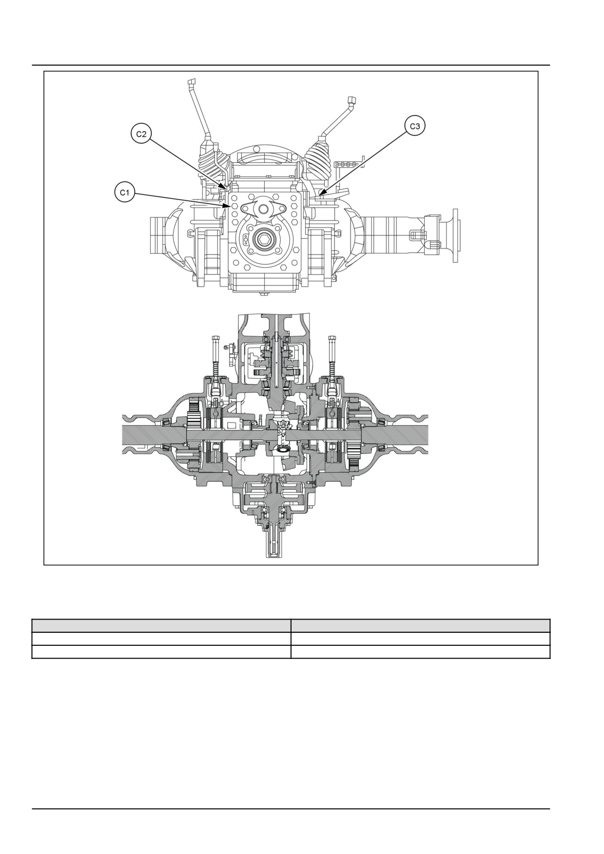
Power Take-Off (PTO) case mounting bolts (C1)
M12 x 1.25
10.00 kgf (22.05 lbf)
Power Take-Off (PTO) lever plate screws (C2)
M8
0.90 kgf (1.98 lbf)
Differential lock pedal screw (C3)
M10 x 1.25
6.00 kgf (13.23 lbf)
31.1 [31.101] / 3
Power Take-Off (PTO) - Rear mechanical control
GNIL14TR00831GA
1
Rear mechanical control - Sealing
Operation description
Sealant specification
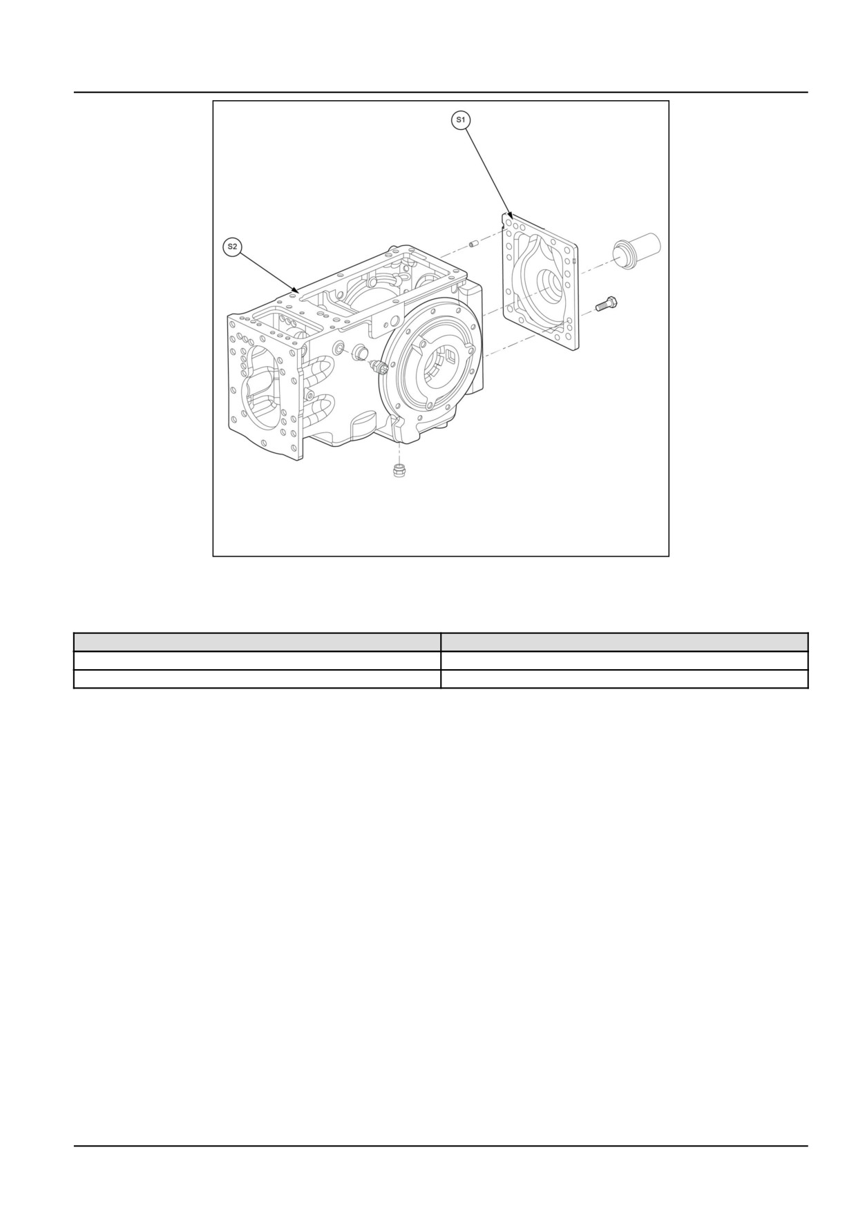
Power Take-Off (PTO) rear cover (S1)
LOCTITE® 518
Hydraulic to transmission housing (S2)
LOCTITE® 518
31.1 [31.101] / 4
Power Take-Off (PTO) - Rear mechanical control
GNIL14TR04296FB
1
Rear mechanical control - Special tools
Operation description
Tools specification
Power Take-Off (PTO) rear cover seal installer
84261381
Yoke and spreader
291051 and 291052
31.1 [31.101] / 5
Power Take-Off (PTO) - Rear mechanical control
Rear mechanical control - Sectional view
GNIL14TR00826FA
1
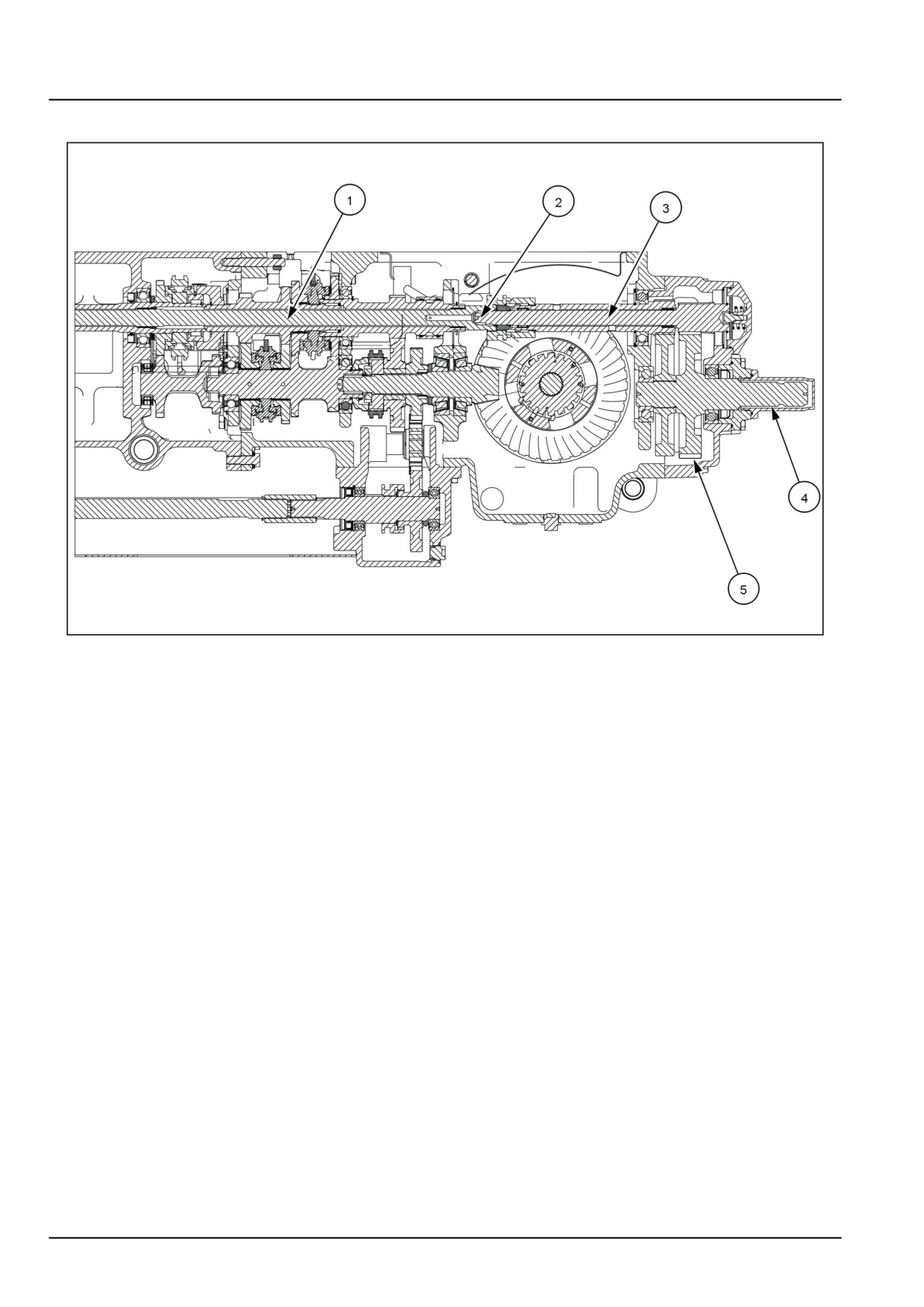
1.
Transmission input shaft
2.
Power Take-Off (PTO) engaging sleeve
3.
Power Take-Off (PTO) input shaft
4.
Power Take-Off (PTO) shaft
5.
Reduction gear
31.1 [31.101] / 6
Power Take-Off (PTO) - Rear mechanical control
Rear mechanical control - Remove
PTO shaft assembly
1. Remove hydraulic lift assembly by following the proce-
dures given in Main lift system - Remove (35.100).
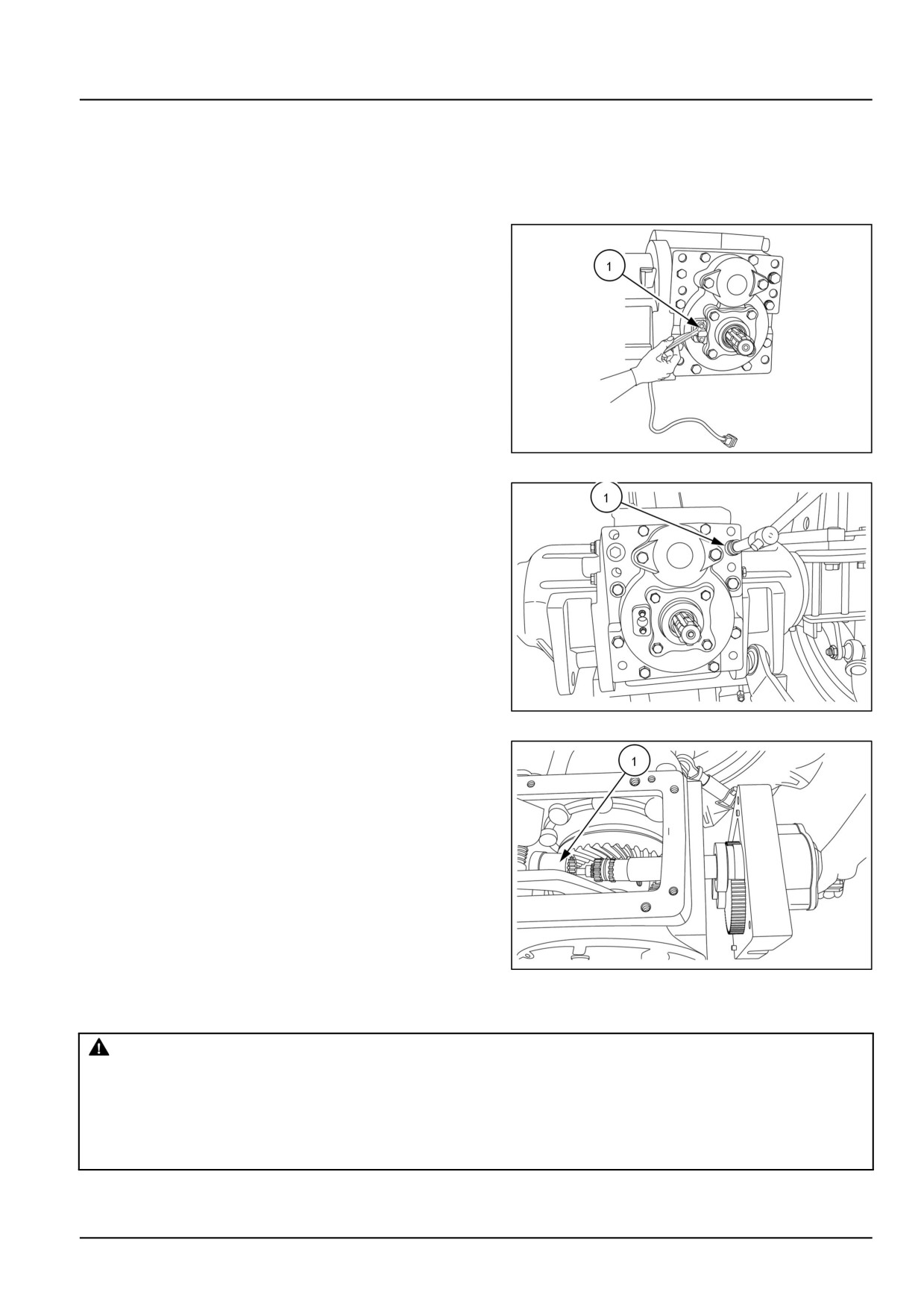
2. Disconnect the PTO RPM sensor electrical connection.
Loosen the bolts (1) and remove the PTO RPM sensor.
GNIL14TR00743AA
1
3. Loosen the bolts (1) securing PTO rear cover to the
differential housing.
GNIL14TR00741AA
2
4. Remove the PTO shaft assembly rear cover. Remove
the PTO engaging coupler (1) and retrieve PTO en-
gage, disengage pad.
GNIL14TR00742AA
3
PTO levers and internal linkages
CAUTION
Avoid injury!
Handle all parts carefully. Do not place your hands or fingers between parts. Use Personal Protec-
tive Equipment (PPE) as indicated in this manual, including protective goggles, gloves, and safety
footwear.
Failure to comply could result in minor or moderate injury.
C0145A
31.1 [31.101] / 7
Power Take-Off (PTO) - Rear mechanical control
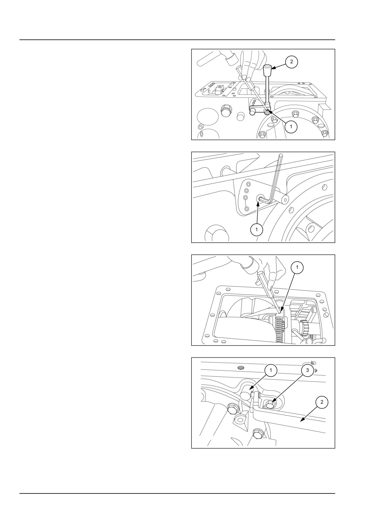
5. Push out roll pin (1) and remove main PTO lever (2)
from the shaft.
GNIL14TR04303AB
4
6. Loosen set screw (1) and remove plate.
GNIL14TR04304AB
5
7. Remove roll pin holding differential lock fork (1) and
PTO coupler fork.
GNIL14TR04305AB
6
8. Remove the differential pedal lever (2) by unscrewing
two bolts (3) securing the bracket.
GNIL14TR04307AB
7
31.1 [31.101] / 8
Power Take-Off (PTO) - Rear mechanical control
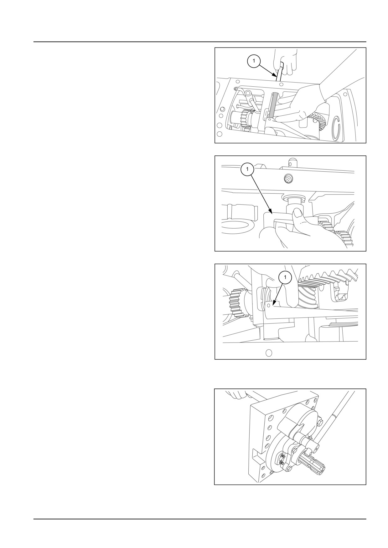
9. Push out the differential lock shaft (1) and PTO lever
shaft.
GNIL14TR04308AB
8
10. Remove PTO fork (1).
GNIL14TR04309AB
9
11. Remove differential lock pedal fork (1).
GNIL14TR04310AB
10
PTO input shaft cover
12. Loosen the bolts and remove the PTO input shaft
cover.
GNIL14TR00744AA
11
31.1 [31.101] / 9
Power Take-Off (PTO) - Rear mechanical control
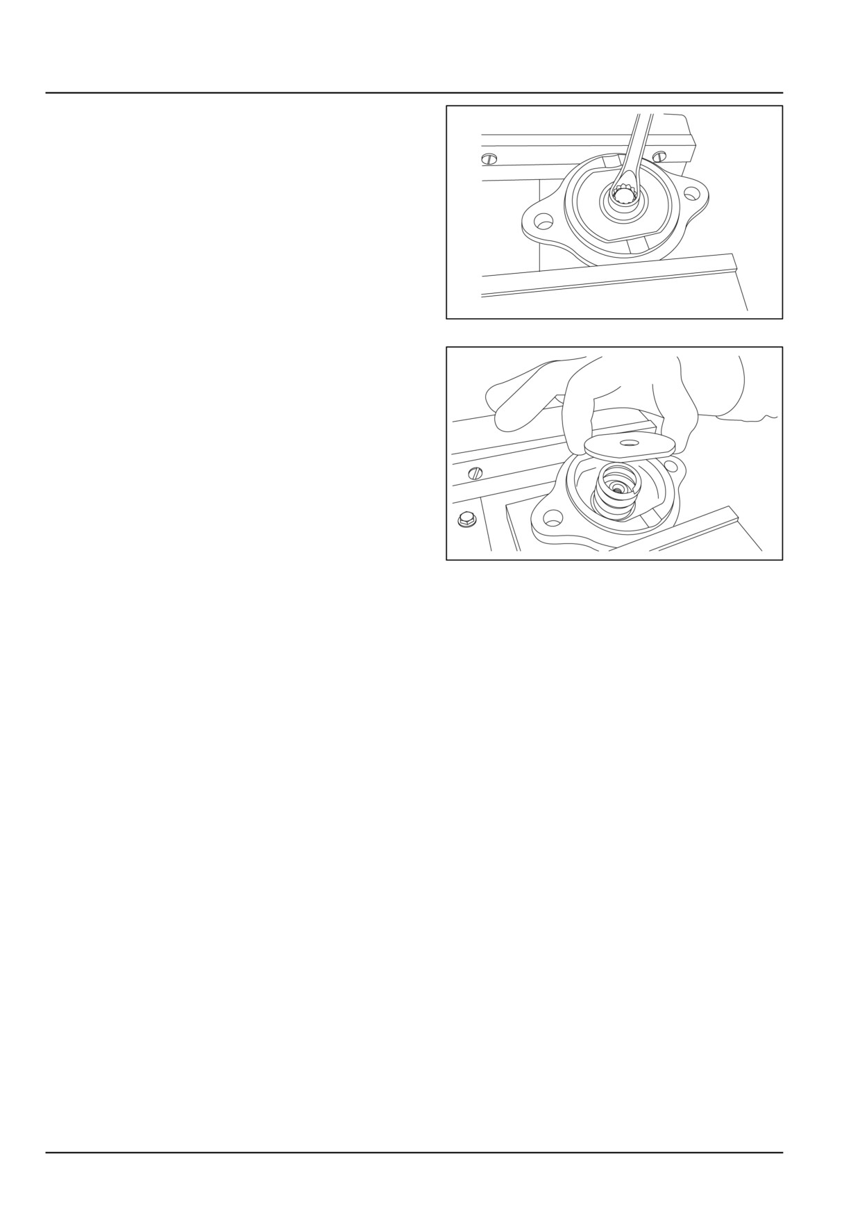
13. Loosen the bolt from the inner side of the cover plate.
GNIL14TR00738AA
12
14. Retrieve the inner plate and the spring from the cover.
GNIL14TR00739AA
13
31.1 [31.101] / 10
Power Take-Off (PTO) - Rear mechanical control
Rear mechanical control - Install
For installation, follow the removal process in reverse
order.
NOTE: Torque all the bolts to correct value. See Rear mechanical control - Torque (31.101).
31.1 [31.101] / 11
Index
Power Take-Off (PTO) - 31
Rear mechanical control - 101
Rear mechanical control - General specification
3
Rear mechanical control - Install
11
Rear mechanical control - Remove
7
Rear mechanical control - Sealing
4
Rear mechanical control - Sectional view
6
Rear mechanical control - Special tools
5
Rear mechanical control - Torque
3
31.1 [31.101] / 12
Power Take-Off (PTO) - 31
One-speed rear Power Take-Off (PTO) - 110
Workmaster™ 50
Workmaster™ 60
Workmaster™ 70
31.2 [31.110] / 1
Contents
Power Take-Off (PTO) - 31
One-speed rear Power Take-Off (PTO) - 110
FUNCTIONAL DATA
One-speed rear Power Take-Off (PTO)
Overview
3
SERVICE
One-speed rear Power Take-Off (PTO)
Disassemble
4
Assemble
5
31.2 [31.110] / 2
Power Take-Off (PTO) - One-speed rear Power Take-Off (PTO)
One-speed rear Power Take-Off (PTO) - Overview
The Power Take-Off (PTO) transfers engine power di-
rectly to mounted, semi-mounted or trailed equipment via
a splined shaft at the rear of the tractor.
The system utilizes the standard 6 -splines shaft designed
to operator at 540 RPM, the speed at which most Power
Take-Off (PTO) driven equipment is designed to run.
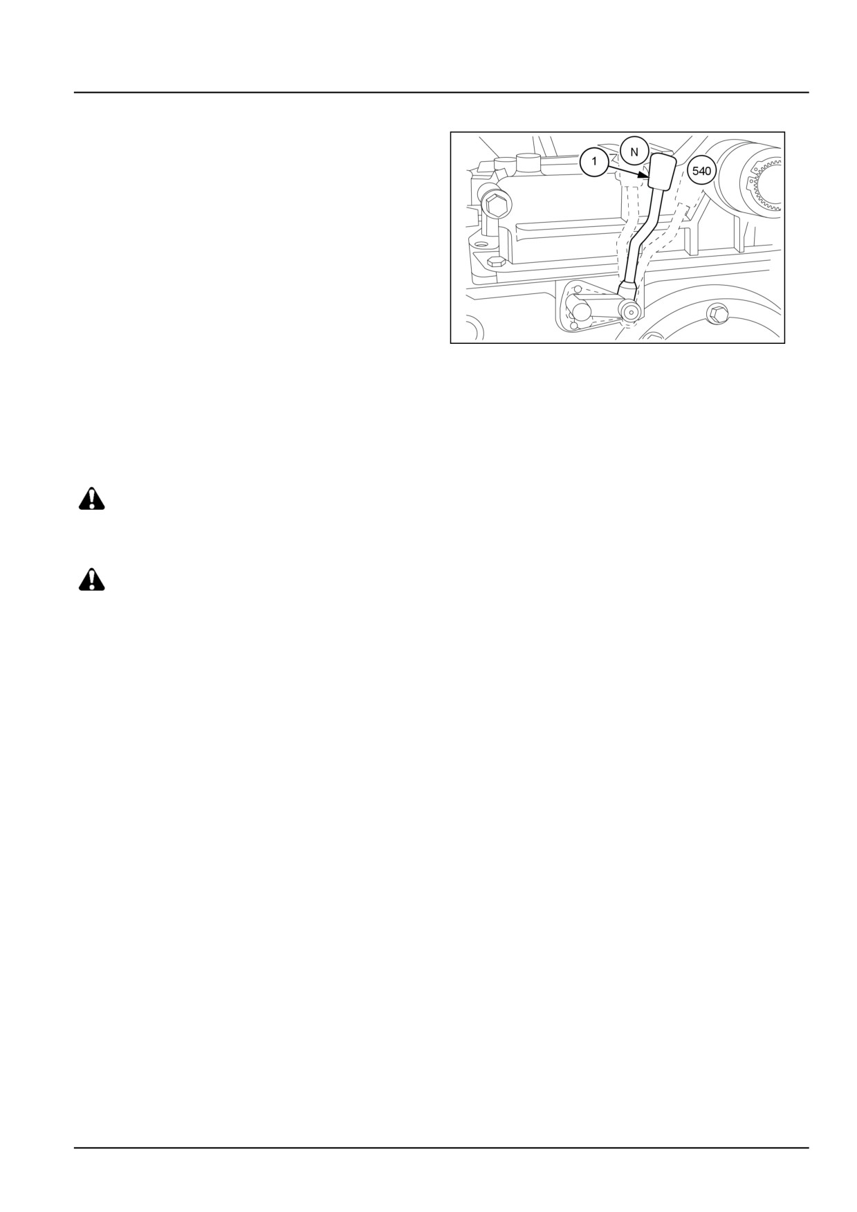
The Power Take-Off (PTO) input shaft front end can be
connected and disconnected to the transmission input
shaft by means of a lever (1) on the left hand-side of the
transmission unit.
Move the lever (1) backward to engage the PTO. Move
the lever (1) forward to disengage the PTO.
GNIL14TR04298AB
1
The rear end of the Power Take-Off (PTO) input shaft
is connected to the Power Take-Off (PTO) output shaft
through reduction gears.
The standard speed of 540 PTO RPM can be obtained at
2575 engine rpm.
DANGER
To avoid inadvertent movement of the implement,
disengage the Power Take-Off (PTO) after each use
WARNING
Whenever operating Power Take-Off (PTO) equipment,
observe the following precautions:
31.2 [31.110] / 3
Power Take-Off (PTO) - One-speed rear Power Take-Off (PTO)
One-speed rear Power Take-Off (PTO) - Disassemble
1. Remove the hydraulic lift assembly, PTO external con-
trol and PTO cover. See Rear mechanical control -
Remove (31.101).
2. Remove the PTO input shaft cover. Remove the PTO
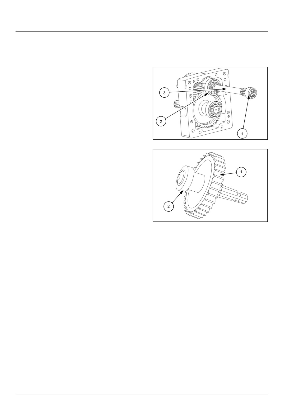
coupler (1). Remove the bearing (2). Remove the PTO
drive shaft assembly (3) from the PTO rear cover.
GNIL14TR00768AA
1
3. Remove the Power Take-Off (PTO) driven shaft along
with gear (1) and take out bearing (2) if necessary.
NOTE: Gear is the integral part of Power Take-Off (PTO)
shaft in single speed Power Take-Off (PTO)
GNIL14TR04324AB
2
31.2 [31.110] / 4
Power Take-Off (PTO) - One-speed rear Power Take-Off (PTO)
One-speed rear Power Take-Off (PTO) - Assemble
1. For assembly, follow the disassembly process in re-
verse order.
2. Fit Power Take-Off (PTO) shaft seal (1) as shown in
figure.
GNIL14TR04325AA
1
31.2 [31.110] / 5
Index
Power Take-Off (PTO) - 31
One-speed rear Power Take-Off (PTO) - 110
One-speed rear Power Take-Off (PTO) - Assemble
5
One-speed rear Power Take-Off (PTO) - Disassemble
4
One-speed rear Power Take-Off (PTO) - Overview
3
31.2 [31.110] / 6
Power Take-Off (PTO) - 31
Two-speed rear Power Take-Off (PTO) - 114
Workmaster™ 50
Workmaster™ 60
Workmaster™ 70
31.3 [31.114] / 1
Contents
Power Take-Off (PTO) - 31
Two-speed rear Power Take-Off (PTO) - 114
FUNCTIONAL DATA
Two-speed rear Power Take-Off (PTO)
Overview
3
SERVICE
Two-speed rear Power Take-Off (PTO)
Disassemble
4
Inspect
6
Assemble
7
31.3 [31.114] / 2
Power Take-Off (PTO) - Two-speed rear Power Take-Off (PTO)
Two-speed rear Power Take-Off (PTO) - Overview
The Power Take-Off (PTO) transfers engine power di-
rectly to mounted, semi-mounted or trailed equipment via
a splined shaft at the rear of the tractor.
The system utilizes the standard 6 -splines shaft designed
to operator at 540 RPM, the speed at which most Power
Take-Off (PTO) driven equipment is designed to run.
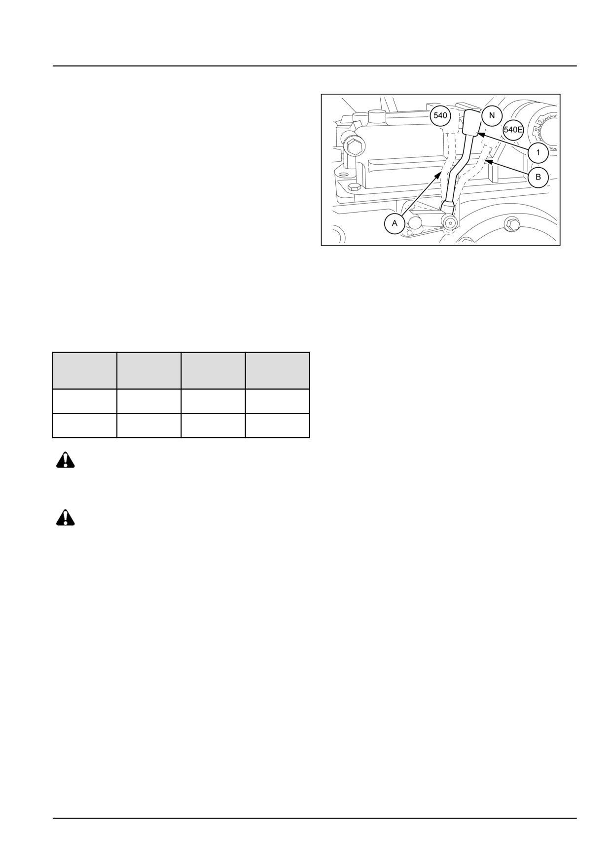
The Power Take-Off (PTO) input shaft front end can be
connected and disconnected to the transmission input
shaft by means of a lever (1) on the left hand-side of the
transmission unit.
The rear end of the Power Take-Off (PTO) input shaft
GNIL14TR00553AA
1
is connected to the Power Take-Off (PTO) output shaft
through reduction gears.
The standard speed of 540 PTO RPM can be obtained
at 2575 engine rpm. Shift lever forward to get normal
540 PTO RPM, and shift rearward to get ground speed or
540E PTO. 540 Economy RPM can be obtained at 2016
engine RPM.
Power
Engine
Lever
Application
Take-Off
position
(PTO)
Rotavator
540 RPM
2575 RPM
Forward
thresher, etc.
Water pump,
540E RPM
2016 RPM
Backward
etc
DANGER
To avoid inadvertent movement of the implement,
disengage the Power Take-Off (PTO) after each use
WARNING
Whenever operating Power Take-Off (PTO) equipment,
observe the following precautions:
31.3 [31.114] / 3
Power Take-Off (PTO) - Two-speed rear Power Take-Off (PTO)
Two-speed rear Power Take-Off (PTO) - Disassemble
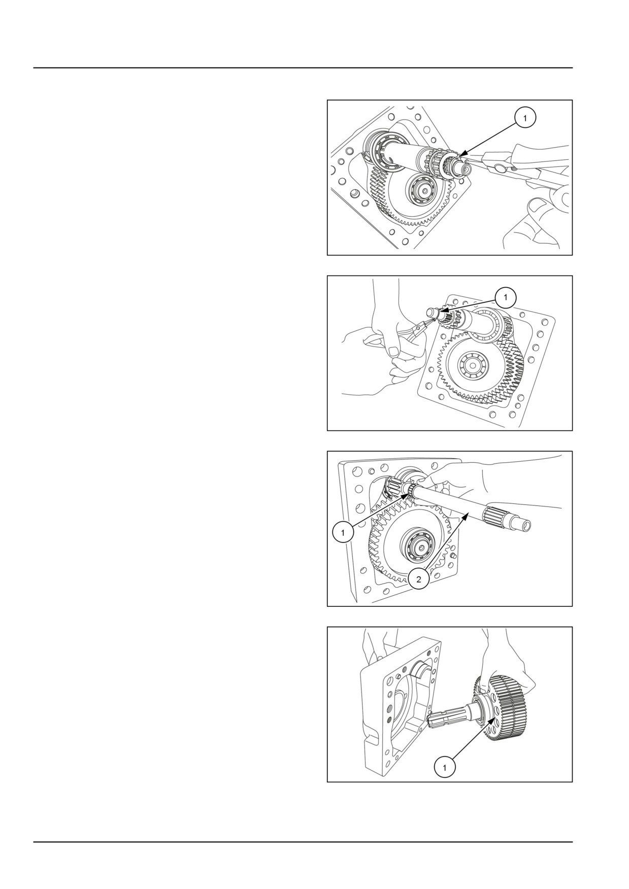
1. Remove circlip lock (1) from the outer hollow Power
Take-Off (PTO) shaft and remove coupling gear.
GNIL14TR00745AA
1
2. Remove the circlip lock (1), needle roller bearing. Take
out the hollow Power Take-Off (PTO) shaft.
GNIL14TR04312AB
2
3. Retrieve the needle roller bearing (1) Remove the PTO
input shaft cover. Remove the Power Take-Off (PTO)
drive shaft assembly (2) from the rear cover.
GNIL14TR00749AA
3
4. Remove Power Take-Off (PTO) output shaft and gear
assembly (1).
GNIL14TR00750AA
4
31.3 [31.114] / 4
Power Take-Off (PTO) - Two-speed rear Power Take-Off (PTO)
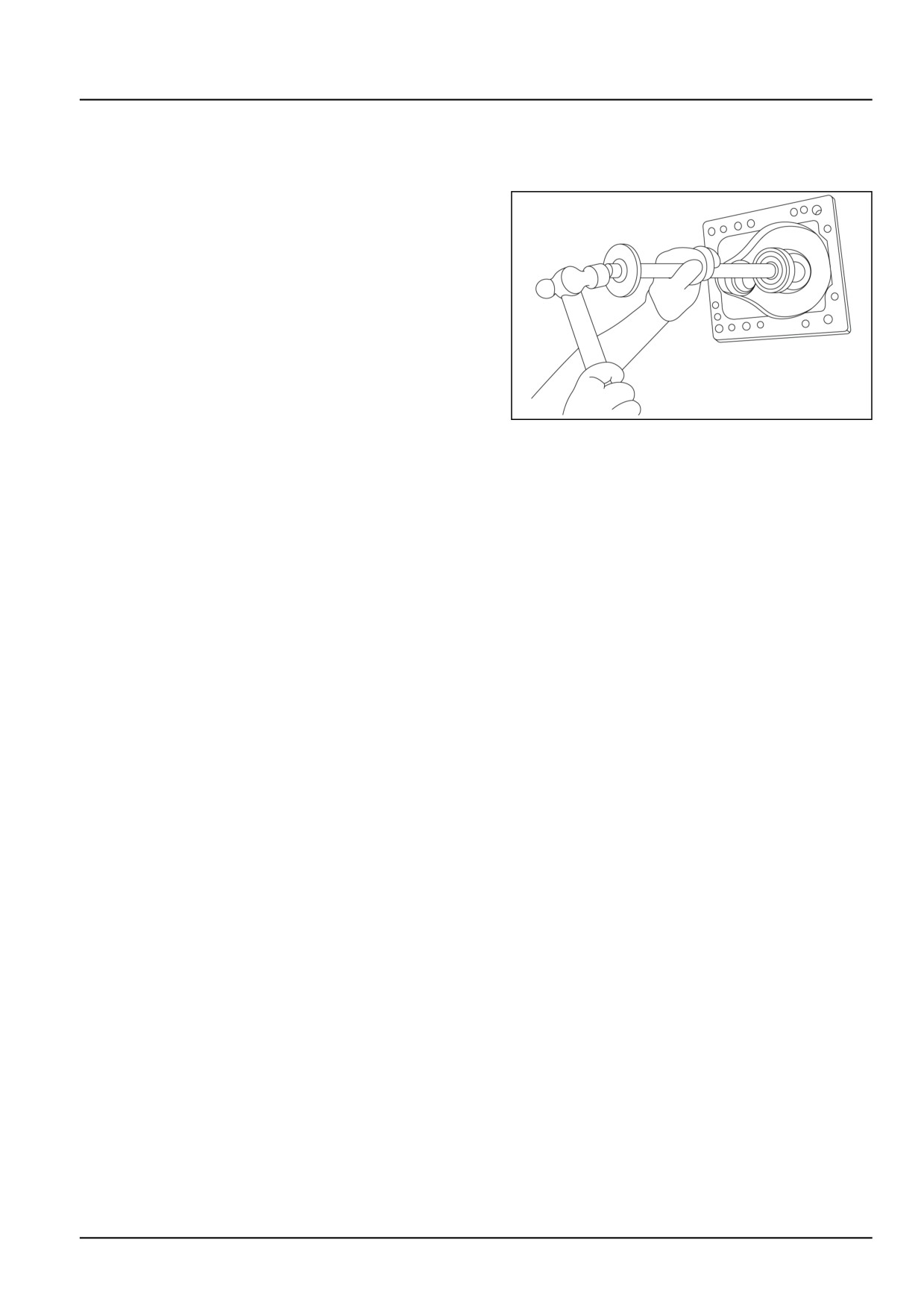
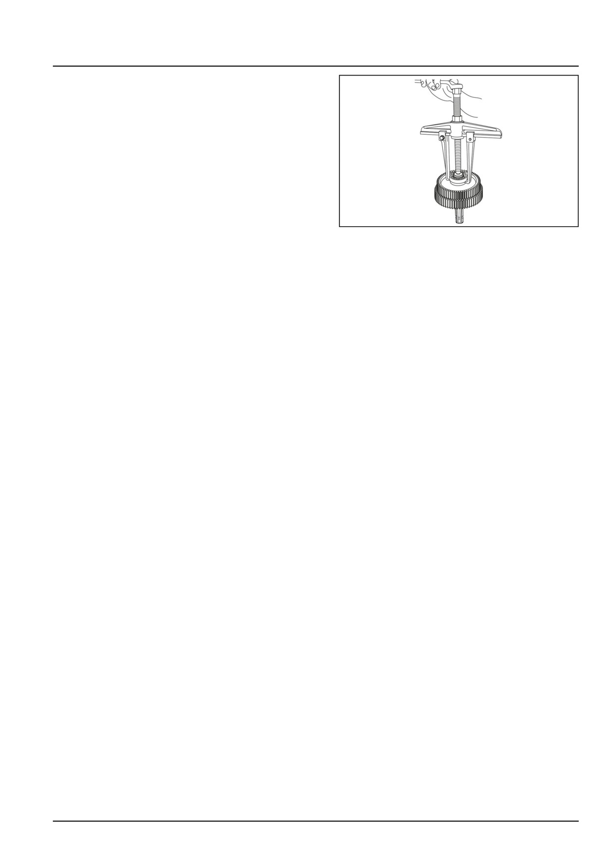
5. To dismantle Power Take-Off (PTO) gears assembly
use special tool number 291051 and 291052 as shown
in figure to remove bearing.
GNIL14TR00751AA
5
31.3 [31.114] / 5
Power Take-Off (PTO) - Two-speed rear Power Take-Off (PTO)
Two-speed rear Power Take-Off (PTO) - Inspect
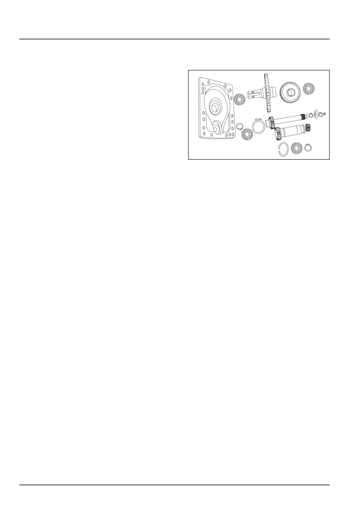
PTO shaft assembly inspection
Check the gears shaft and bearings, for wear and dam-
ages. If required replace by new parts.
GNIL14TR04319AA
1
31.3 [31.114] / 6
Power Take-Off (PTO) - Two-speed rear Power Take-Off (PTO)
Two-speed rear Power Take-Off (PTO) - Assemble
Power Take-Off (PTO) shaft assembly
Re-install Power Take-Off (PTO) shaft assembly in dif-
ferential housing observing the following:
• Re-assembling follows the disassembly procedure in
reverse. Refer to Two-speed rear Power Take-Off
(PTO) - Disassemble (31.114).
• Refer to figure for correct orientation of the gears and
sleeve.
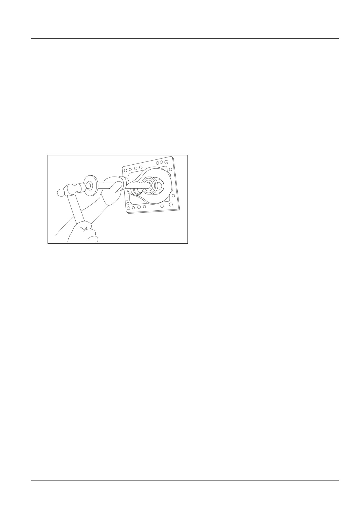
• Check seals and replace if damaged. Fit the Power
Take-Off (PTO) oil seal in the Power Take-Off (PTO)
rear cover with the help of special tool number
84261386
GNIL14TR04318AA
1
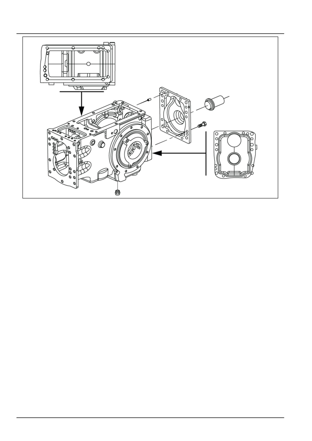
• Before reassembling Power Take-Off (PTO) cover,
Thoroughly clean and degrease mating surfaces and
apply a 2.00 mm (0.08 in) bead of sealant following
the pattern shown in 2
• Tighten the rear cover bolts to 50 N·m (37 lb ft).
NOTE: Keep bigger collar of the gear toward bearings.
31.3 [31.114] / 7
Power Take-Off (PTO) - Two-speed rear Power Take-Off (PTO)
GNIL14TR04320GA
2
31.3 [31.114] / 8
Index
Power Take-Off (PTO) - 31
Two-speed rear Power Take-Off (PTO) - 114
Two-speed rear Power Take-Off (PTO) - Assemble
7
Two-speed rear Power Take-Off (PTO) - Disassemble
4
Two-speed rear Power Take-Off (PTO) - Inspect
6
Two-speed rear Power Take-Off (PTO) - Overview
3
31.3 [31.114] / 9
CNH Industrial America New Holland Site 100 Brubaker Avenue New Holland, Pennsylvania United States
17557
SERVICE - Technical Publications & Tools
PRINTED IN U.S.A.
All rights reserved. No part of the text or illustrations of this publication may be reproduced.
NEW HOLLAND policy is one of continuous improvement and the right to change prices, specification or equipment
at any time without notices is reserved.
All data given in this publication is subject to production variations. Dimensions and weight are approximate only and
the illustrations do not necessarily show products in standard condition. For exact information about any particular
product, please consult your NEW HOLLAND Dealer.
EN
SERVICE MANUAL
Brakes and controls
Workmaster™ 50
Workmaster™ 60
Workmaster™ 70
33
Contents
Brakes and controls - 33
[33.120] Mechanical service brakes
33.1
33
Brakes and controls - 33
Mechanical service brakes - 120
Workmaster™ 50
Workmaster™ 60
Workmaster™ 70
33.1 [33.120] / 1
Contents
Brakes and controls - 33
Mechanical service brakes - 120
TECHNICAL DATA
Mechanical service brakes
General specification
3
Special tools
3
Torque
3
Sealing
4
FUNCTIONAL DATA
Mechanical service brakes
Exploded view
6
Overview
7
Sectional view
8
SERVICE
Mechanical service brakes
Remove
9
Inspect
12
Install
13
Brake control pedals and shafts
Remove
15
Adjust
17
DIAGNOSTIC
Mechanical service brakes
Troubleshooting
18
33.1 [33.120] / 2

Brakes and controls - Mechanical service brakes
Mechanical service brakes - General specification
Type
Oil immersed disc brakes acting on differential axle shaft
Control
Service brake
Mechanical, independent pedal control
Parking brake
Mechanical, hand lever pull type
Number of discs per side
3 each side
Brake oil specification
APGSAE 20W30
Nominal brake disc thickness
4.65 mm (0.183 in)
Brake pedal free play
50 - 55 mm (1.97 - 2.17 in)
Mechanical service brakes - Special tools
Description
Tool number
Installer, brake boot in trumpet housing
84261390
Installer, rubber boot outer in brake linkage groove
84261391
Mechanical service brakes - Torque
Description
Thread size
Torque
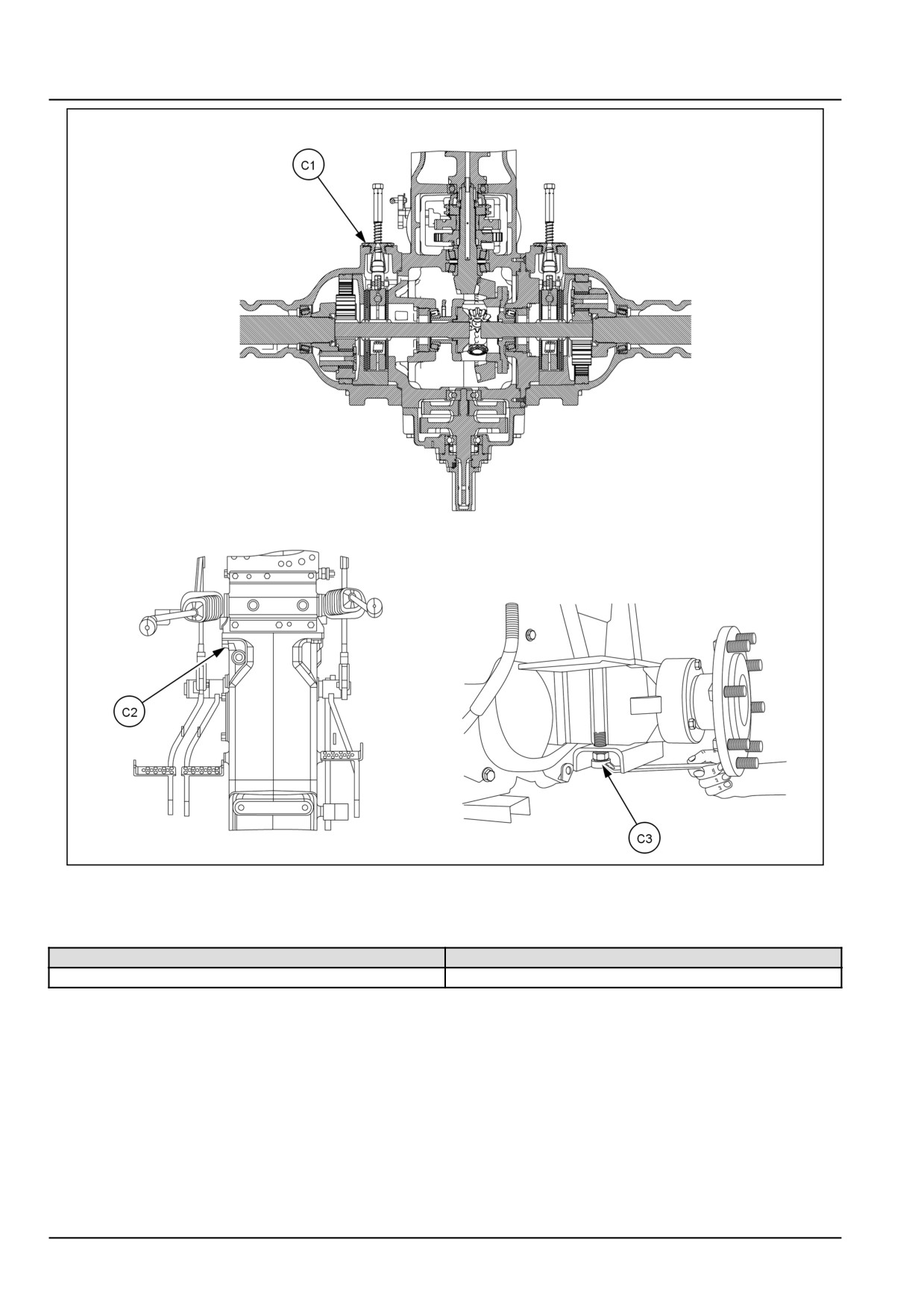
Hand brake pawl assembly mounting bolt (C1)
M12 x 1.25
10 kgf (22 lbf)
Clutch housing to transmission (C2)
M12 x 1.25
10 kgf (22 lbf)
ROPS bolts (C3)
M16 1.5
20 kgf (44 lbf)
33.1 [33.120] / 3
Brakes and controls - Mechanical service brakes
GNIL14TR00832GA
1
Mechanical service brakes - Sealing
Operation description
Sealant specification
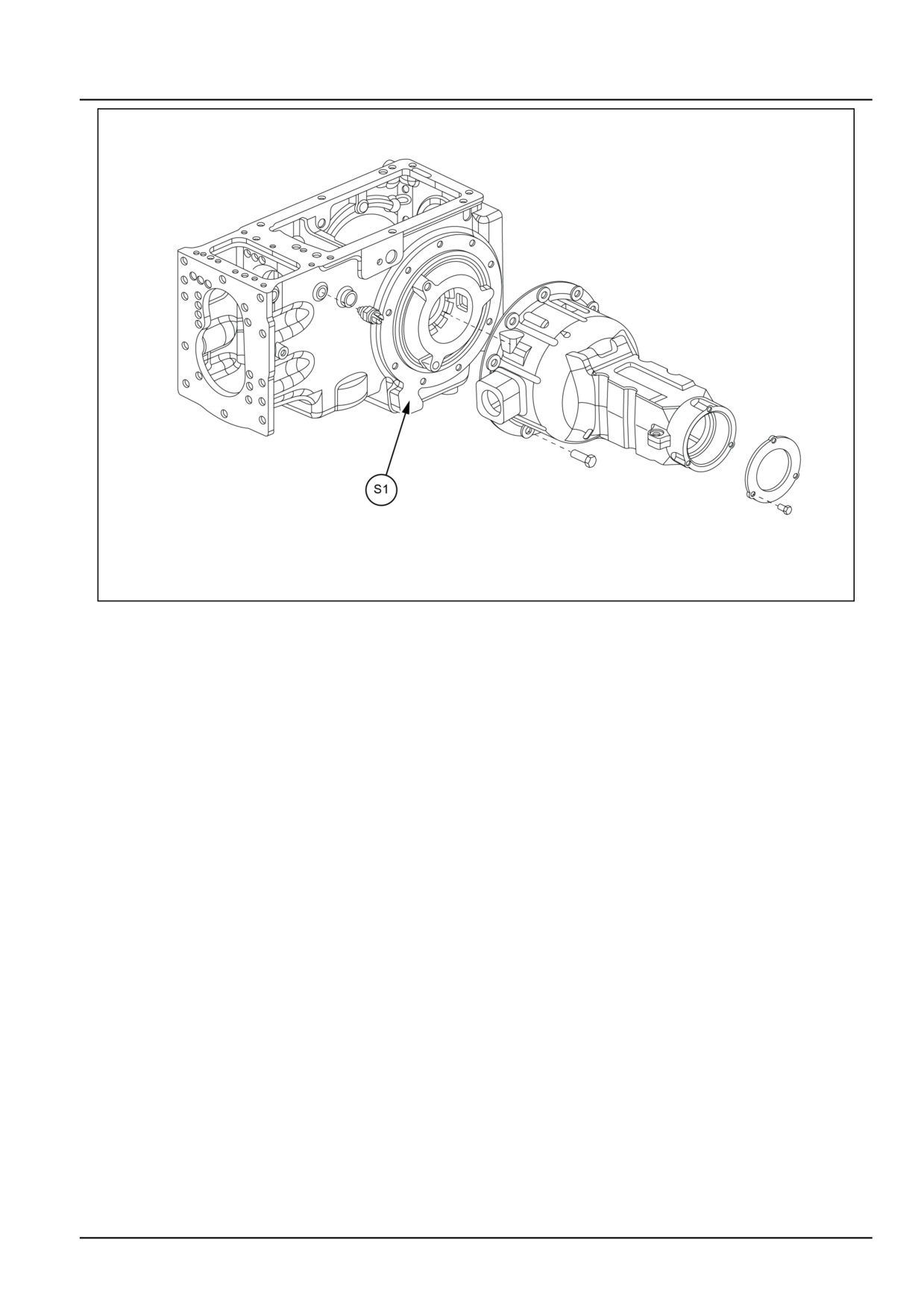
Buckle up of rear axle housing to differential housing (S1)
LOCTITE® 518™
33.1 [33.120] / 4
Brakes and controls - Mechanical service brakes
GNIL14TR04327FB
1
33.1 [33.120] / 5
Brakes and controls - Mechanical service brakes
Mechanical service brakes - Exploded view
GNIL14TR00841GB
1
33.1 [33.120] / 6
Brakes and controls - Mechanical service brakes
Mechanical service brakes - Overview
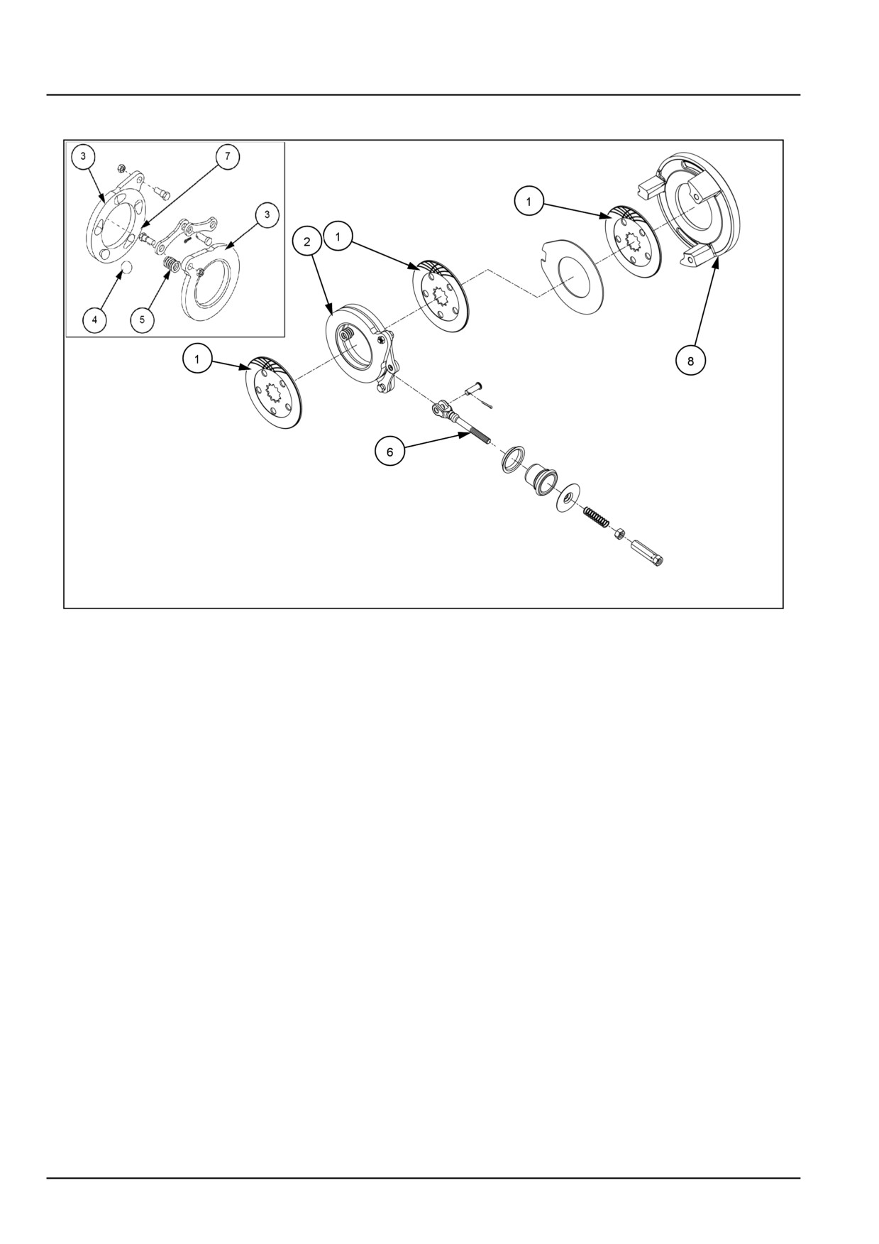
See Mechanical service brakes - Exploded view (33.120).
Oil immersed brakes used, has two brake discs (1) both externally lined with friction material are supported by brake
actuator (2) mounted on brake housing (8). An actuating assembly is mounted between the brake discs (1), which
consists of two discs (3) separated by steel balls (4) but connected by short springs (5). Lugs on the discs are attached
to a yoke (6) on the operating rod.
When the tractors moving, the brake discs rotate with the axle shaft. If brake pedal is depressed, its associated
brake links cause this actuating discs to turn in opposite directions. As the pressure plates turn, the balls (4) clamped
between the actuating discs roll over the inclined surfaces of their sockets (7). In the plates, thus causing the actuating
discs to move axially outwards to contact the rotating brake discs which in turn contact the inner faces of the brake
housing (8) and differential support and back-up discs. This movement increases the axial force on the housing,
support back-up disc and actuator and produce brake torque. This action causes the axle shaft, hence the associated
driving wheel of the tractor, to slow down and then stop rotating completely. On release of the brake, retracting springs
(5) return the plates to their original positions.
The force exerted by the driver is transmitted to the brake assembly by a system of levers and rods. The actuating
system not only connects the pedal with the brake but also increases the relatively small force available at the pedal
to the much larger force required to brake the vehicle. It can also permit the braking effort to be divided between the
axles in the required proportion.
Left wheel brake pedal can be retained in the applied position by means of latch controlled by a hand lever fitted at
right hand side, below operator’s seat used as a parking brake.
33.1 [33.120] / 7
Brakes and controls - Mechanical service brakes
Mechanical service brakes - Sectional view
GNIL14TR00833FA
1
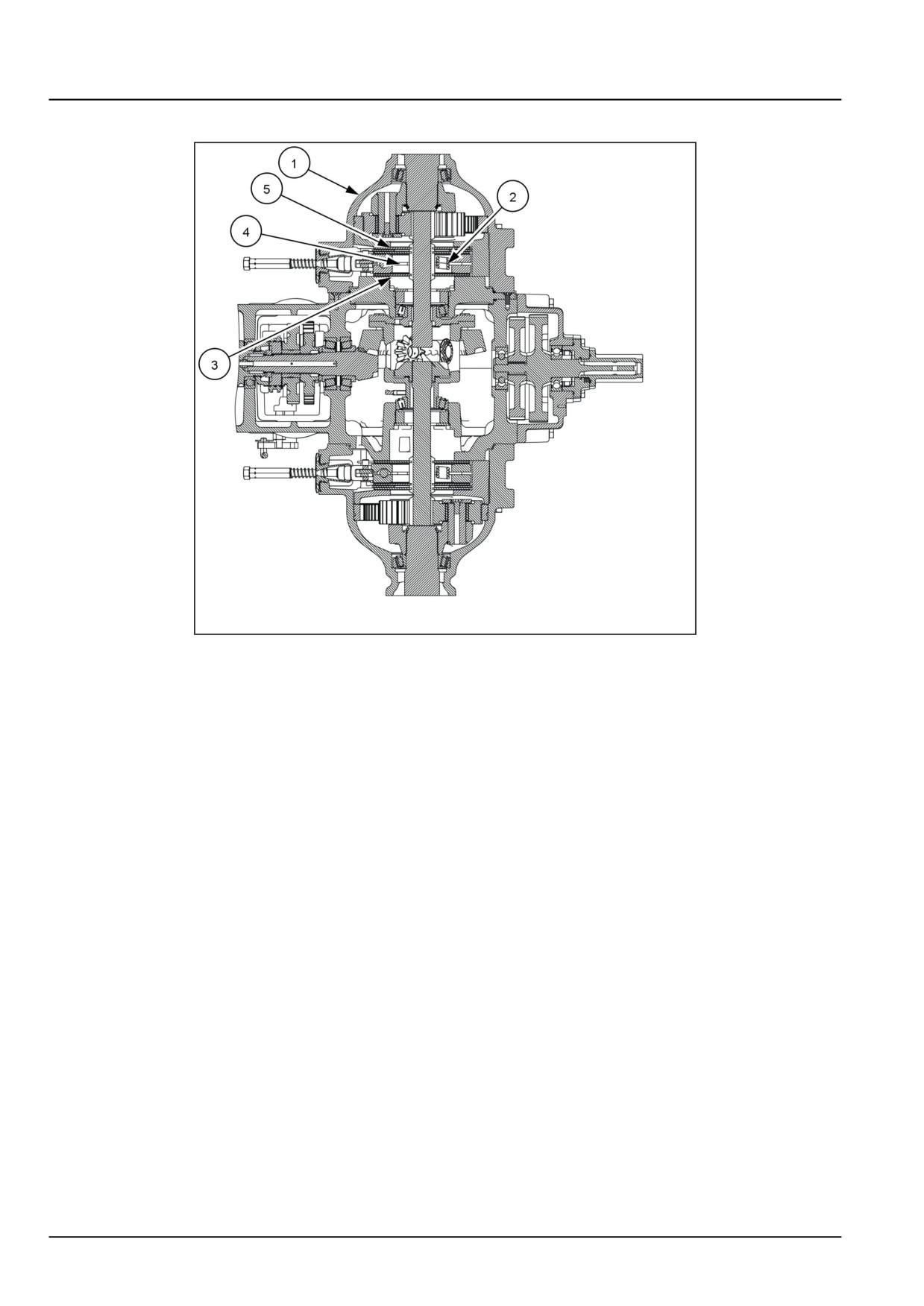
(1) Final drive housing
(2) Actuator return spring
(3) Inner friction plate
(4) Actuating discs
(5) Outer friction plate
33.1 [33.120] / 8