New Holland Tractor Workmaster 50 / Workmaster 60 / Workmaster 70 / Tier 4B (final). SERVICE MANUAL - page 12
Contents
Hydraulic systems - 35
Hydraulic hand control - 355
FUNCTIONAL DATA
Hydraulic hand control
Overview
3
SERVICE
Hydraulic hand control
Disassemble
5
Assemble
7
35.6 [35.355] / 2
Hydraulic systems - Hydraulic hand control
Hydraulic hand control - Overview
This is a live hydraulic system, where gear type hydraulic
pump is mounted directly to timing case. transmission
lubrication oil is used also as hydraulic oil. This system
described here mechanically senses changes in the draft
loading via the top link of the three point linkage. The
system allows the operator to select position control, draft
control, mixed control and float.
CAUTION
Hydraulic filter is to be changed at regular intervals as
recommended. Hydraulic and transmission parts may
get damaged if filter is choked. Always use genuine
NEW HOLLAND filters.
GNIL14TR00580AA
1
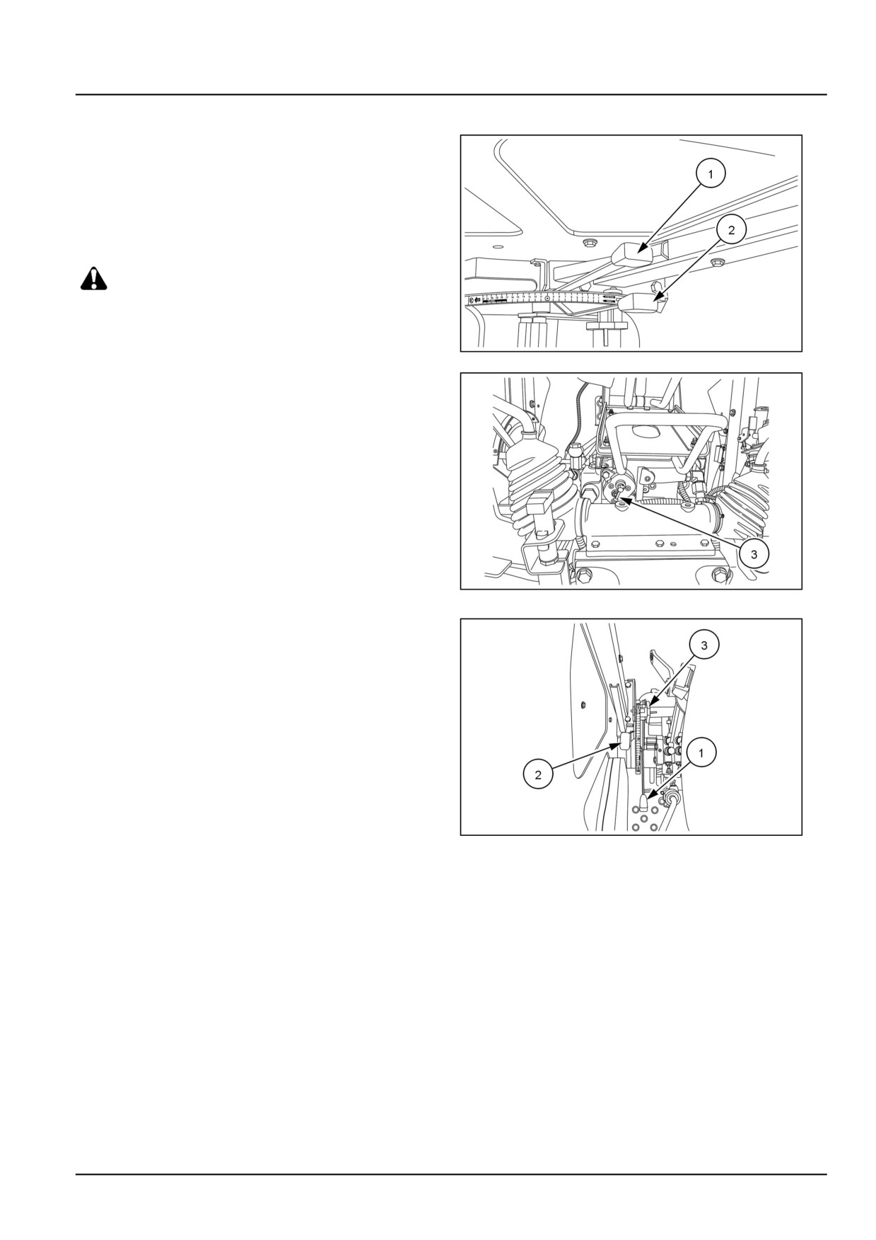
The system is operated by position control lever (1), draft
control lever (2), and response control (3).
GNIL14TR00798AA
2
NOTE: Some mounted or semi-mounted equipment may
interfere with and cause damage to tractor sheet metal.
To avoid damage check for clearance between tractor and
implements.
Position control operation
Position control provides accurate control of implements
such as sprayers, rakes, rotary tillers, etc. that operate
above the ground. Once set, position control will maintain
the selected implement height.
NOTE: Always set the system to position control at any
time when not actually operating in draft control, such
GNIL14TR00813AA
3
as when attaching or transporting equipment or when no
equipment is attached.
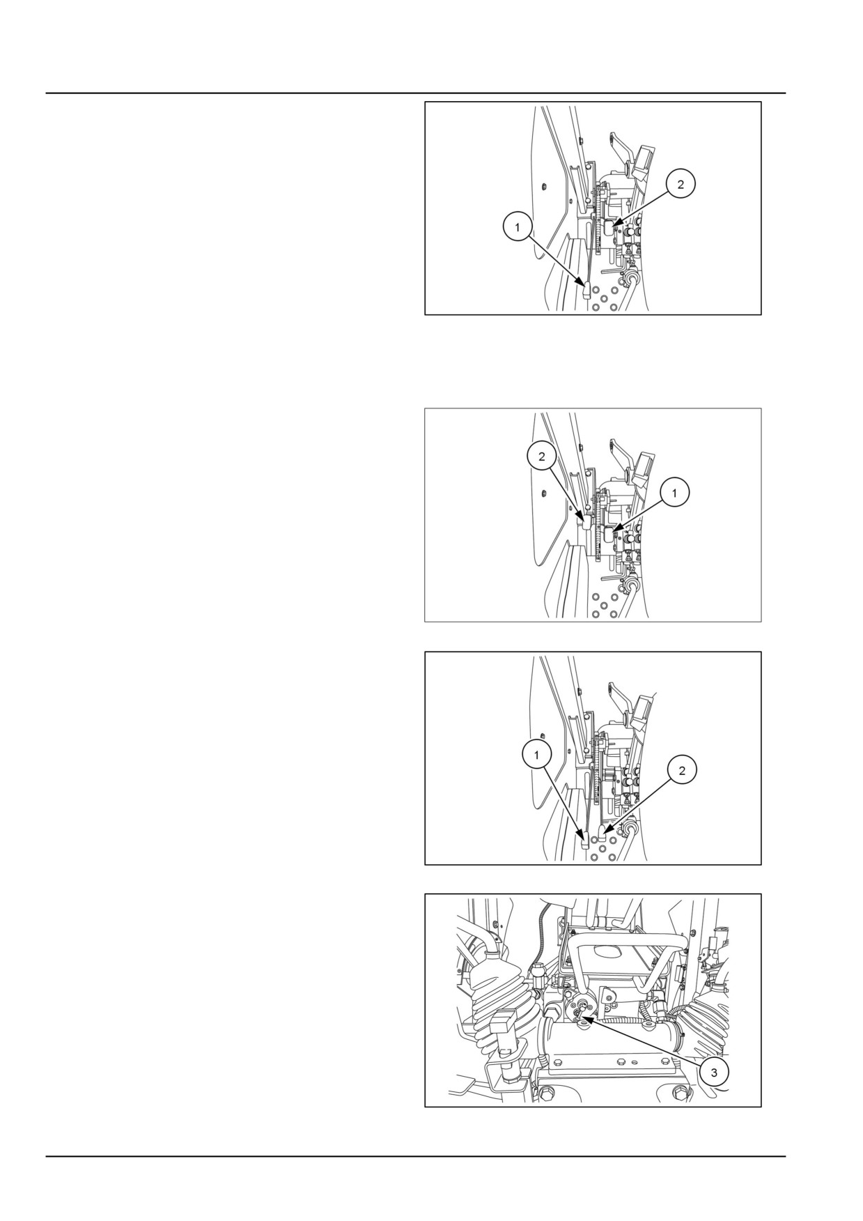
Move the draft control lever (1) fully forward in the quad-
rant. Set the required implement height/depth using the
position control lever (2). Pull the lever back to raise
the implement, push forward to lower. Implement height/
depth is relative to the position of the lever in quadrant.
An adjustable stop (3) is provided to enable the lever to
be returned to the required working position.
35.6 [35.355] / 3
Hydraulic systems - Hydraulic hand control
Draft control operation
Draft control is most suitable for mounted or semi-
mounted implements operating in the ground. Changes
in the working depth or changes in soil resistance will
cause draft loading on the implement to increase or
decrease.
Move the position control lever (1) fully forward. Lower
the implement in to the work using draft control lever (2).
Push the lever forward to increase the draft loading. Pull
rearwards to reduce the draft loading. Forward movement
of the draft control lever will increase the implement depth
and rearward movement will reduce the depth.
GNIL14TR00814AA
4
Once set, tractor hydraulic system will automatically ad-
just the implement depth to maintain an even pull on the
tractor and minimise wheel slip.
Combined position and draft control opera-
tion
On very light soil or varying soil types in the same field,
it may be necessary to use the draft control and position
control in combination. When starting work, lower the im-
plement to the required depth by means of the draft control
lever (1).
When the implement reaches the required depth, raise
the position control lever (2) back until the lift arms tend to
rise. The lift linkage is now in draft control but the position
control function prevents the system from sinking too deep
when draft reduces.
GNIL14TR00815AA
5
Float operation
Move the position control lever (1) and the draft control
lever (2) fully forward. The 3-point linkage will now be
free to ‘float’ or follow the ground contour, a feature useful
for scraper blades etc.
GNIL14TR00816AA
6
Response control
The response control knob (1) varies the speed of drop of
the lower links.
Clockwise rotation - Decreases speed of drop
Anti-clockwise rotation - Increases speed of drop
NOTE: To lock implements in transport position when driv-
ing on road, fully raise position control lever (1), 6 and
screw in (rotate clockwise) knob (1), 7.
GNIL14TR00798AA
7
35.6 [35.355] / 4
Hydraulic systems - Hydraulic hand control
Hydraulic hand control - Disassemble
WARNING
Avoid injury!
Handle all parts carefully. Do not place your hands or fingers between parts. Use Personal Protec-
tive Equipment (PPE) as indicated in this manual, including protective goggles, gloves, and safety
footwear.
Failure to comply could result in death or serious injury.
W0208A
Lift external controls can be disassembled and re-
assembled only with the lift on a work bench or on
a rotary stand. It is possible to remove only position
control lever when the lift assembly is mounted on the
tractor.
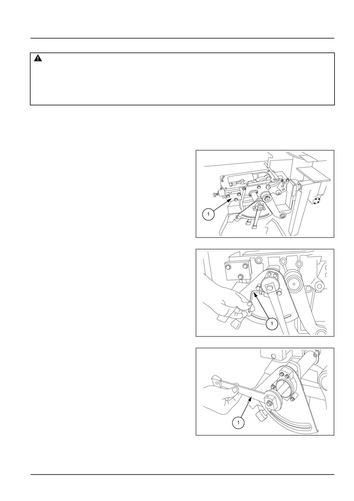
1. Remove the lift from the transmission housing and
place on a work bench or fix on a rotary stand.
GNIL14TR04610AB
1
2. Loosen set screws (1) and remove position control
lever hub along with nylon washer.
NOTE: Nylon washers can be removed from hub by loos-
ening Allen screw.
GNIL14TR04611AA
2
3.
1. After loosening set screws remove position control
lever (1).
2. Remove bolts (2) to take out sector plate.
GNIL14TR04612AB
3
35.6 [35.355] / 5
Hydraulic systems - Hydraulic hand control
4.
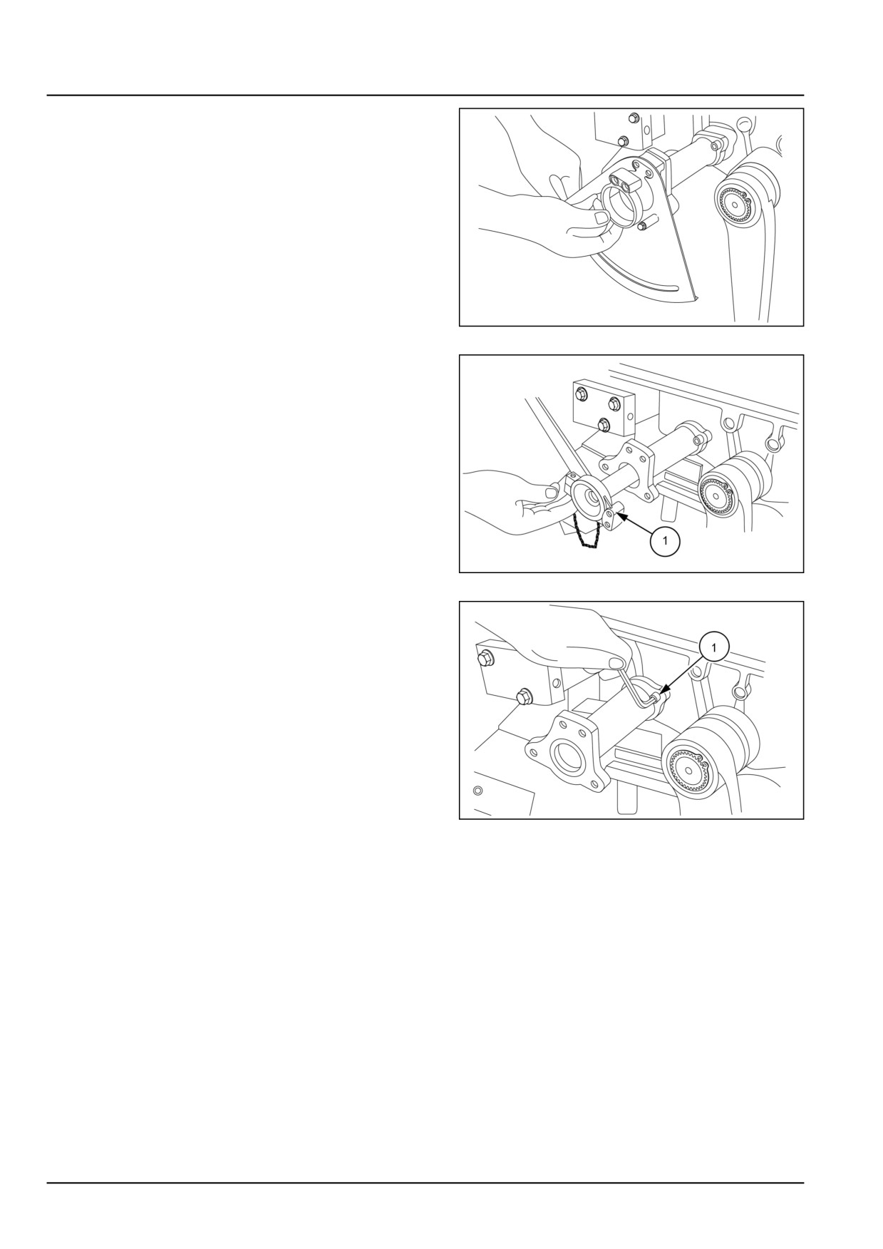
1. Remove draft control lever hub by loosening set
screws (1) along with the nylon washer.
2. Remove sector plate.
GNIL14TR04613AB
4
5. Draft control lever is welded on draft control shaft. Re-
move the position control shaft and draft control shaft
to remove the draft control lever internal linkages.
1. Remove set screw.
2. Remove linkages from the shafts.
NOTE: Remove hydraulic linkages to remove set screw.
GNIL14TR04614AB
5
6. Remove set screw (1) to remove shaft.
GNIL14TR04615AA
6
35.6 [35.355] / 6
Hydraulic systems - Hydraulic hand control
Hydraulic hand control - Assemble
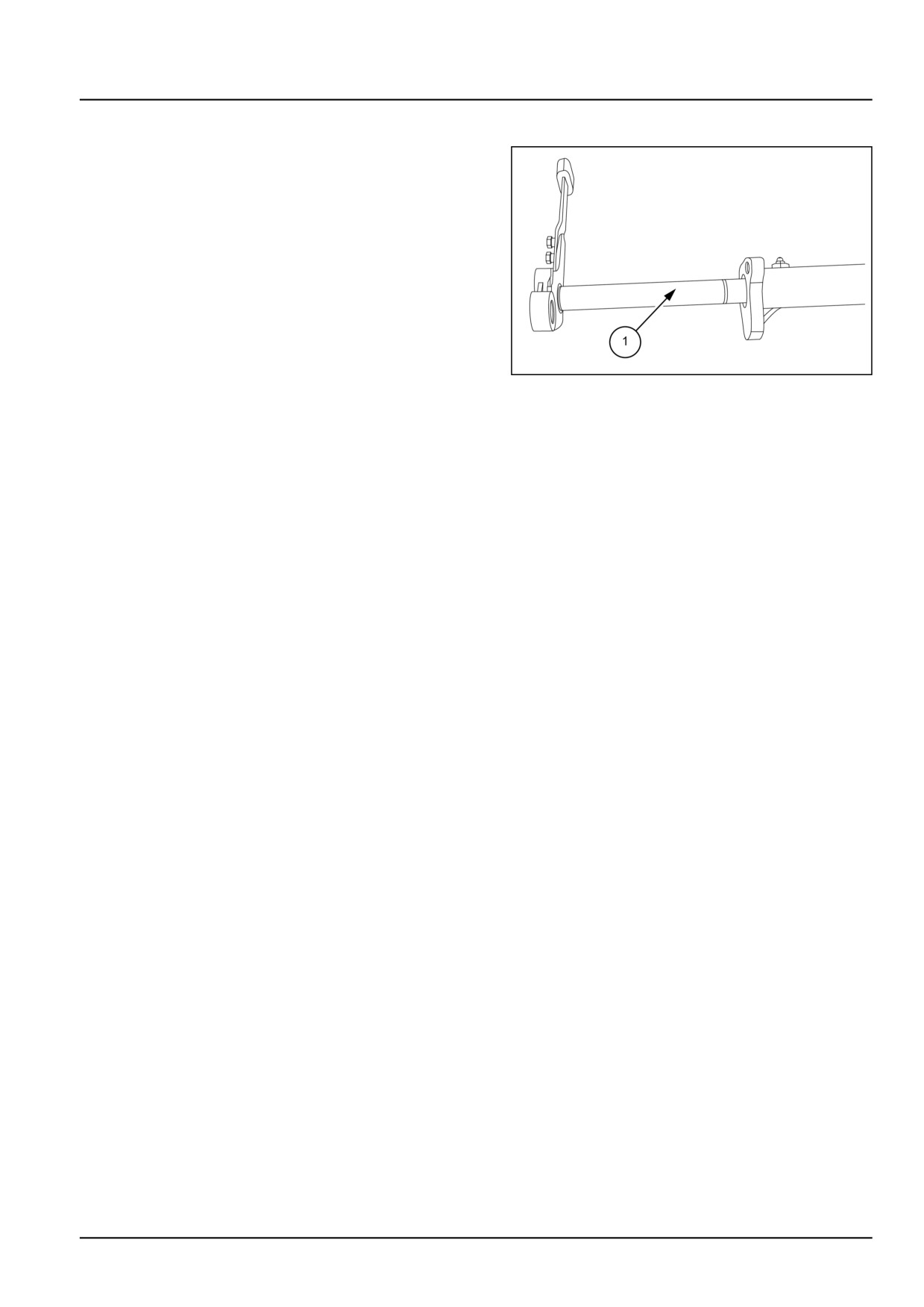
1. Reassemble the lift external controls following the dis-
assemble procedure in reverse.
2. Check the O-rings on the draft control shaft for any
damage. If necessary, replace by new O-rings.
GNIL14TR04616AB
1
35.6 [35.355] / 7
Index
Hydraulic systems - 35
Hydraulic hand control - 355
Hydraulic hand control - Assemble
7
Hydraulic hand control - Disassemble
5
Hydraulic hand control - Overview
3
35.6 [35.355] / 8
Hydraulic systems - 35
Main control valve - 359
Workmaster™ 50
Workmaster™ 60
Workmaster™ 70
35.7 [35.359] / 1
Contents
Hydraulic systems - 35
Main control valve - 359
FUNCTIONAL DATA
Main control valve
Overview
3
SERVICE
Main control valve
Remove (Distributor assembly)
8
Install
9
35.7 [35.359] / 2
Hydraulic systems - Main control valve
Main control valve - Overview
The distributor is pre-set to perform three phases.
A. Neutral phase
B. Lifting phase
C. Lowering phase
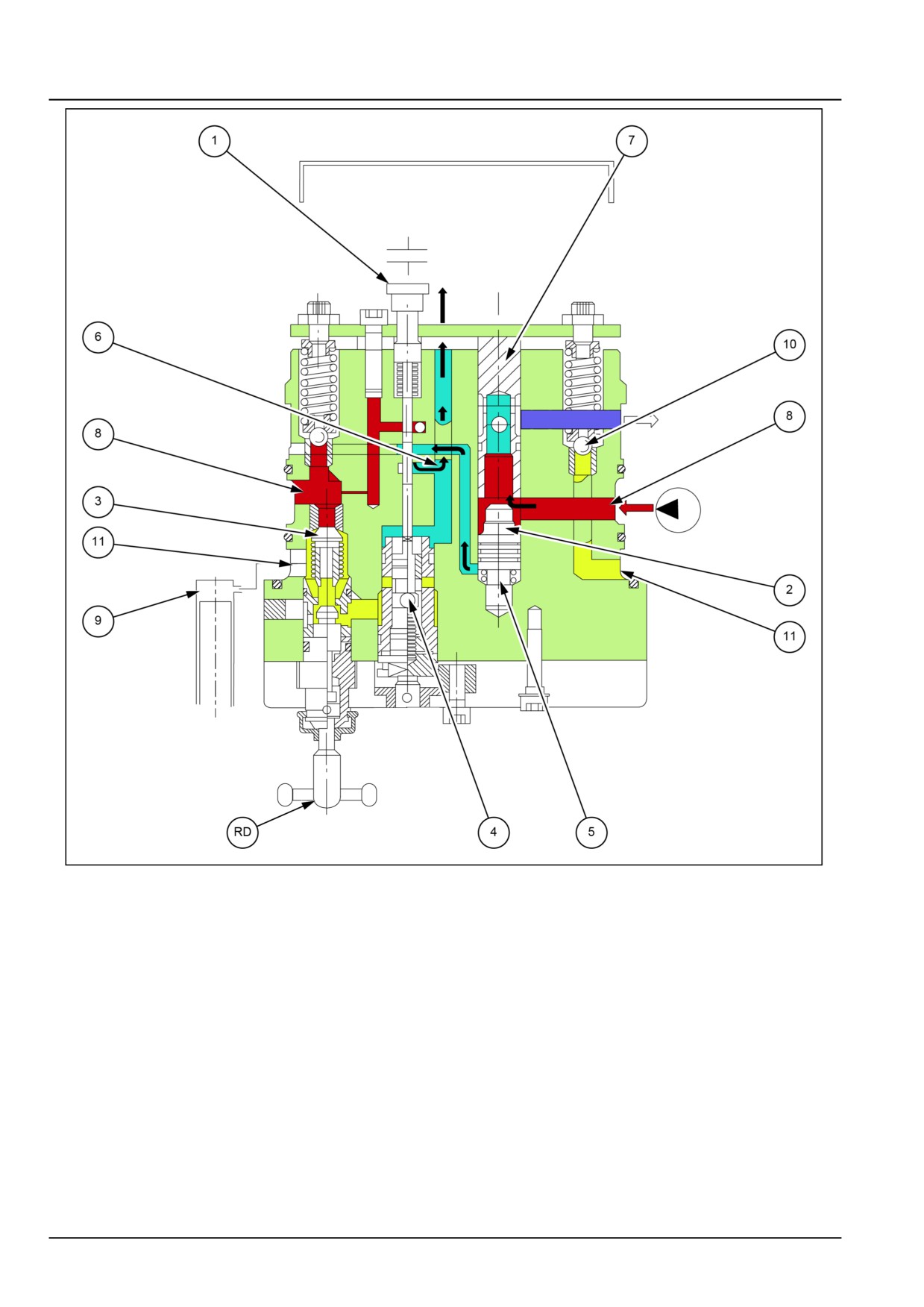
A. Neutral phase
In this phase the control valve keeps pressure on the oil contained in the cylinder thus allowing the oil coming from
the pump to flow freely to the tank.
In this phase the control spool (1) is in such a position to connect the chamber (5) of the differential valve (2) directly
to the discharge through hole (6).
The oil coming from the pump enters the annular duct (8) and moves the differential valve (2) upwards which then
opens the discharge hole (7) and enables the oil to go to the tank.
The oil contained in the cylinder (9) is kept under pressure by the check valve (3), by the discharge valve (4) and safety
valve (10) connected to the cylinder (9) by the annular duct (11) thus holding the load applied to the lifting arms.
The safety valve (10) secures protection from any possible over-pressure during the implement movement.
35.7 [35.359] / 3
Hydraulic systems - Main control valve
GNIL14TR00834GA
1
35.7 [35.359] / 4
Hydraulic systems - Main control valve
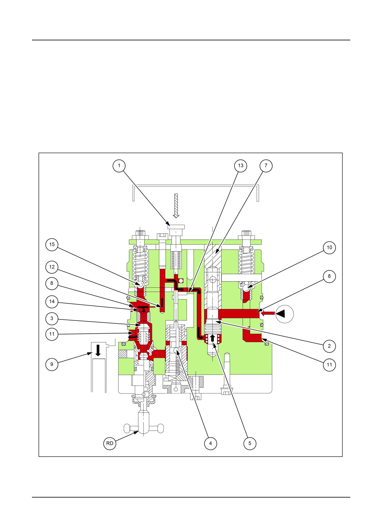
B. Lifting phase
During this phase, the control valve supplies the oil under pressure to the cylinder (9) and it consequently lifts the
arms.
The control spool (1) is in such a position to connect the chamber (5) of the differential valve (2) with the oil coming
from the pump through annular duct (8) and holes (12) and (13) making in this way the valve itself to close.
The oil from the pump finding the differential valve (2) closed goes to cylinder, pass the hole (14) opens the check
valve (3) enters in the annular duct (11) and enters the chamber (9).
The lifting speed depends on the pump RPM.
In this phase the maximum lifting pressure is controlled by the safety valve (15) that is connected to annular duct (8)
through hole (14) and then to the oil inlet.
GNIL14TR00835GA
2
35.7 [35.359] / 5
Hydraulic systems - Main control valve
C. Lowering phase
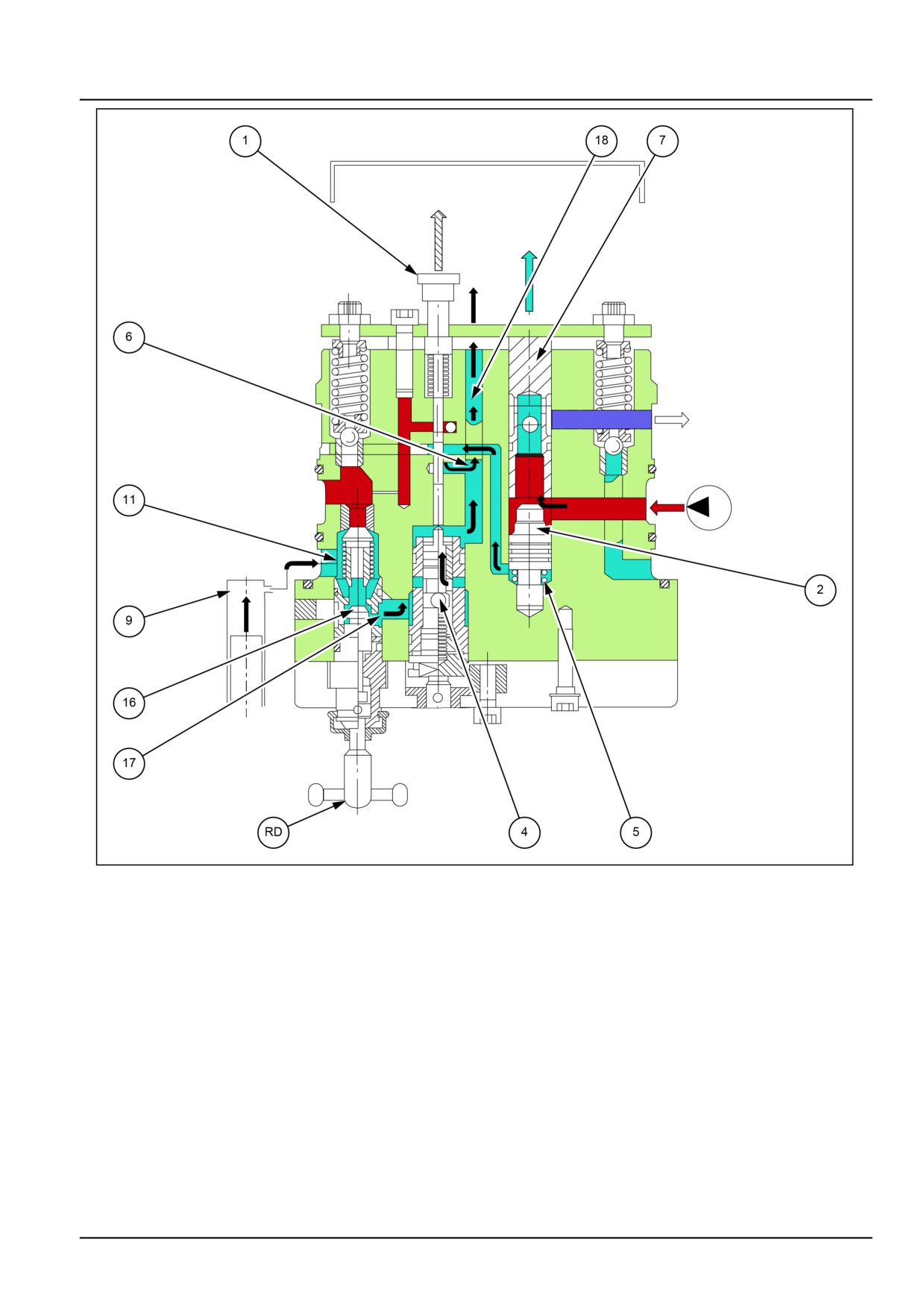
During this phase, the control valve supplies at the same time the oil coming from the pump and the oil contained in
the cylinder to the discharge causing the lowering of the arms.
The control spool (1) is in such a position to connect chamber (5) of differential valve directly to the discharge through
hole (6).
The oil coming from the pump enters the annular duct (8) and moves the differential valve (2) upwards which then
opens the discharge hole (7) and enables the oil to go to the tank.
At the same time the pressure oil contained in the cylinder (9) flows to the tank therefore causing the lowering of the
arms.
From chamber (9) the oil goes into the annular duct (11) passing the lowering speed regulation valve (16) through
the connecting hole (17) enter into the discharge valve (4) that is kept open from the spool (1) and goes to discharge
from hole (18).
In this phase the lowering speed of the implement can be adjusted with lever (RD).
By screwing the lever the lowering speed is reduced, by screwing totally the valve (16) is closed on the seat and
therefore the arms are locked for transport safety.
35.7 [35.359] / 6
Hydraulic systems - Main control valve
GNIL14TR00836GA
3
35.7 [35.359] / 7
Hydraulic systems - Main control valve
Main control valve - Remove (Distributor assembly)
WARNING
Avoid injury!
Handle all parts carefully. Do not place your hands or fingers between parts. Use Personal Protec-
tive Equipment (PPE) as indicated in this manual, including protective goggles, gloves, and safety
footwear.
Failure to comply could result in death or serious injury.
W0208A
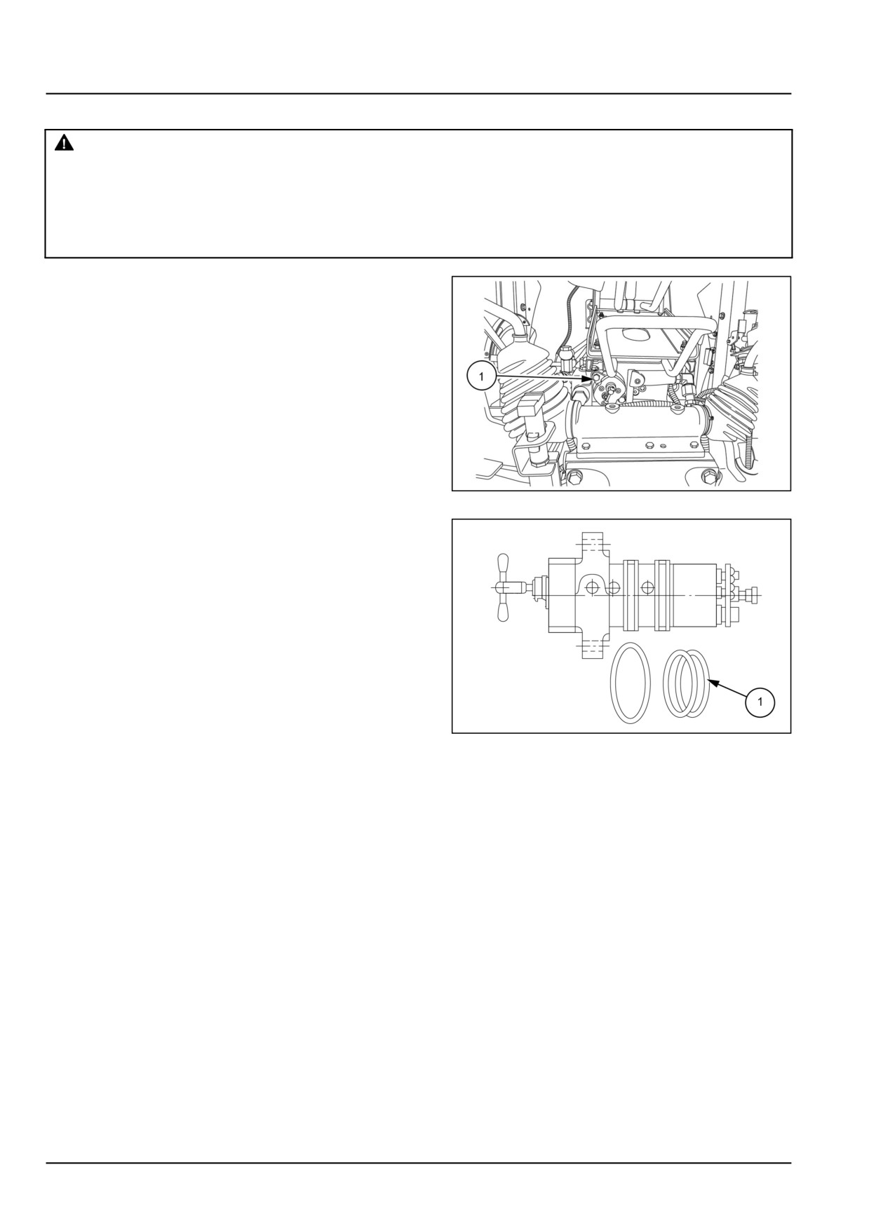
1. Loosen the bolts (1) and remove distributor assembly
from lift housing.
NOTE: Distributor assembly is not serviceable. Replace
complete assembly if found defective.
2. Insert the distributor assembly back on the lift assembly
and tighten the bolts (1).
GNIL14TR00798AA
1
NOTE: Check the O-rings (1) for any damage on distributor
assembly before installing and replace if required.
GNIL14TR04649AB
2
35.7 [35.359] / 8
Hydraulic systems - Main control valve
Main control valve - Install
For installation, follow the reverse order of removal.
35.7 [35.359] / 9
Index
Hydraulic systems - 35
Main control valve - 359
Main control valve - Install
9
Main control valve - Overview
3
Main control valve - Remove (Distributor assembly)
8
35.7 [35.359] / 10
CNH Industrial America New Holland Site 100 Brubaker Avenue New Holland, Pennsylvania United States
17557
SERVICE - Technical Publications & Tools
PRINTED IN U.S.A.
All rights reserved. No part of the text or illustrations of this publication may be reproduced.
NEW HOLLAND policy is one of continuous improvement and the right to change prices, specification or equipment
at any time without notices is reserved.
All data given in this publication is subject to production variations. Dimensions and weight are approximate only and
the illustrations do not necessarily show products in standard condition. For exact information about any particular
product, please consult your NEW HOLLAND Dealer.
EN
SERVICE MANUAL
Steering
Workmaster™ 50
Workmaster™ 60
Workmaster™ 70
41
Contents
Steering - 41
[41.101] Steering control
41.1
[41.200] Hydraulic control components
41.2
[41.206] Pump
41.3
[41.216] Cylinders
41.4
41
Steering - 41
Steering control - 101
Workmaster™ 50
Workmaster™ 60
Workmaster™ 70
41.1 [41.101] / 1
Contents
Steering - 41
Steering control - 101
TECHNICAL DATA
Steering control
Special tools
3
FUNCTIONAL DATA
Steering control
Overview - Hydrostatic steering
4
DIAGNOSTIC
Steering control
Troubleshooting
10
41.1 [41.101] / 2
Steering - Steering control
Steering control - Special tools
Description
Tool number
Steering wheel puller
380001672 and 380003008
Adapter, power steering pressure check
291318
(includes in the set of hydraulic pressure kit 292870)
Power steering rotor spring installer
292927
41.1 [41.101] / 3
Steering - Steering control
Steering control - Overview - Hydrostatic steering
GNIL14TR00870FA
1
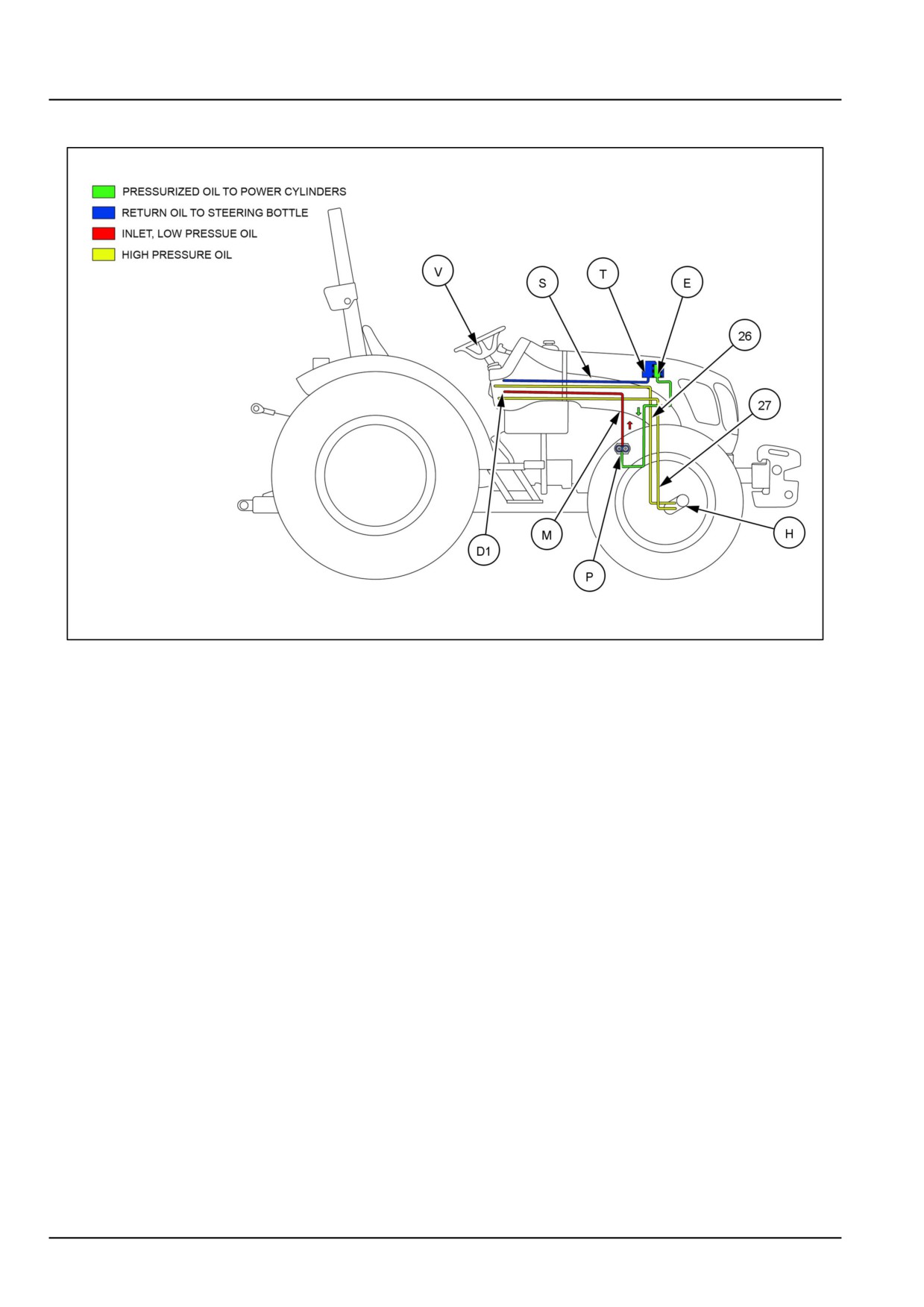
D1. Control valve
P. Hydraulic pump
E. Filter cartridge
S. Return to tank
H. Power cylinder
T. Reservoir
M. Pump outlet line
V. Steering wheel
41.1 [41.101] / 4
Steering - Steering control
GNIL14TR04488JB
2
41.1 [41.101] / 5
Steering - Steering control
A.
Operation in straight-ahead driving position
11.
Cover
B.
Right-hand side (Sd) and left-hand side (Ss)
12.
Spacer
steer
C.
Right-hand side and left-hand side emergency
13, 14.
Oil ports
steer (Sed) and (Ses)
d.
Operation diagram for straight-ahead driving
15.
Rotor inlet passages ( 6 off)
e, f.
Operation diagram for two-stage right-hand
16.
Connecting port ( 12 off) communicating with
side steering
passages ( (15) and (17)) alternatively
E.
Filter cartridge
17.
Pressure passages (6 off) to power cylinder
communicating with the rotor recesses and
ports ( (18) and (20))
g.
Steering system schematics
18.
Right-hand side power cylinder chamber
outlet or exhaust ports (6 pairs)
H.
Power cylinder
19.
Power cylinder exhaust passages ( 6 off)
communicating with ports ( (18) and (20))
M.
Pump outlet line
20.
Left-hand side power cylinder chamber outlet
or exhaust ports ( 6 off)
P.
Hydraulic pump
21.
Oil passage from ports (16) to rotor recesses
S.
Return to tank
22.
Supply ports for passages (15)
T.
Reservoir
23.
Check valve
V.
Steering wheel
24.
Relief valve
a.
Section through control unit with valve (5) in
25.
Washer
neutral
b.
Sections through control unit with valve (5) in
26.
Oil passage to left-hand side power cylinder
right-hand side steer position (for left-hand
chamber
side steer, valve rotation is symmetrical in
opposite direction)
G1, G2.
Gap between pin (1) and rotary valve (5)
27.
Oil passage to right-hand side cylinder
chamber, piston rod side
r1, r2.
Sections through DANFOSS OSPC 100
29.
Thrust bearing
control valve
1.
Drive pin
31.
Seals
2.
Sleeve return springs
32.
Dust excluder
3.
Control valve body
33.
Cylinder safety valves
4.
Check valve
34.
Make-up valves
5.
Rotary valve
35.
O-rings
6.
Valve seat sleeve
36.
Valve adjusting screw
7.
Rotor drive shaft
37.
Plugs
8.
Rotor cam ring
38.
Valve adjusting screw
9.
Rotor
10.
Thrust ring
Hydrostatic steering system is powered (when the engine is running) by steering pump mounted on the front side of
the engine timing gear.
Hydrostatic steering system incorporate a steering pump (1) pressurizes the steering column operated control valve
(2). The pressurized oil from the control valve operates the axle mounted double acting steering cylinder (3).
The control valve is bolted to a bracket mounted on transmission housing and connected to the steering column by
a spindle shaft.
The steering cylinder is fixed at one end to the front axle beam and at the other to an eye on the spindle arm.
The pressure relief value for the system is contained within the steering control valve itself.
Operation
Oil is drawn from the reservoir (4) and into the pump through a filter (3), pressurized by the rotation of the gears and
expelled through the pump outlet port to the steering control valve. The pressurized oil when received at the control
valve is directed to the steering actuating cylinder when the steering wheel is turned.
41.1 [41.101] / 7
Steering - Steering control
The control valve incorporates a metering unit which regulates the volume of oil supplied to the cylinder so that it is
proportional to the angular movement of the steering wheel. The metering unit in combination with the check value
also allows the steering to be operated manually without pressurised oil being supplied from the pump.
The system is fully hydrostatic and as such there is no mechanical connection between the steering column and the
steering wheels.
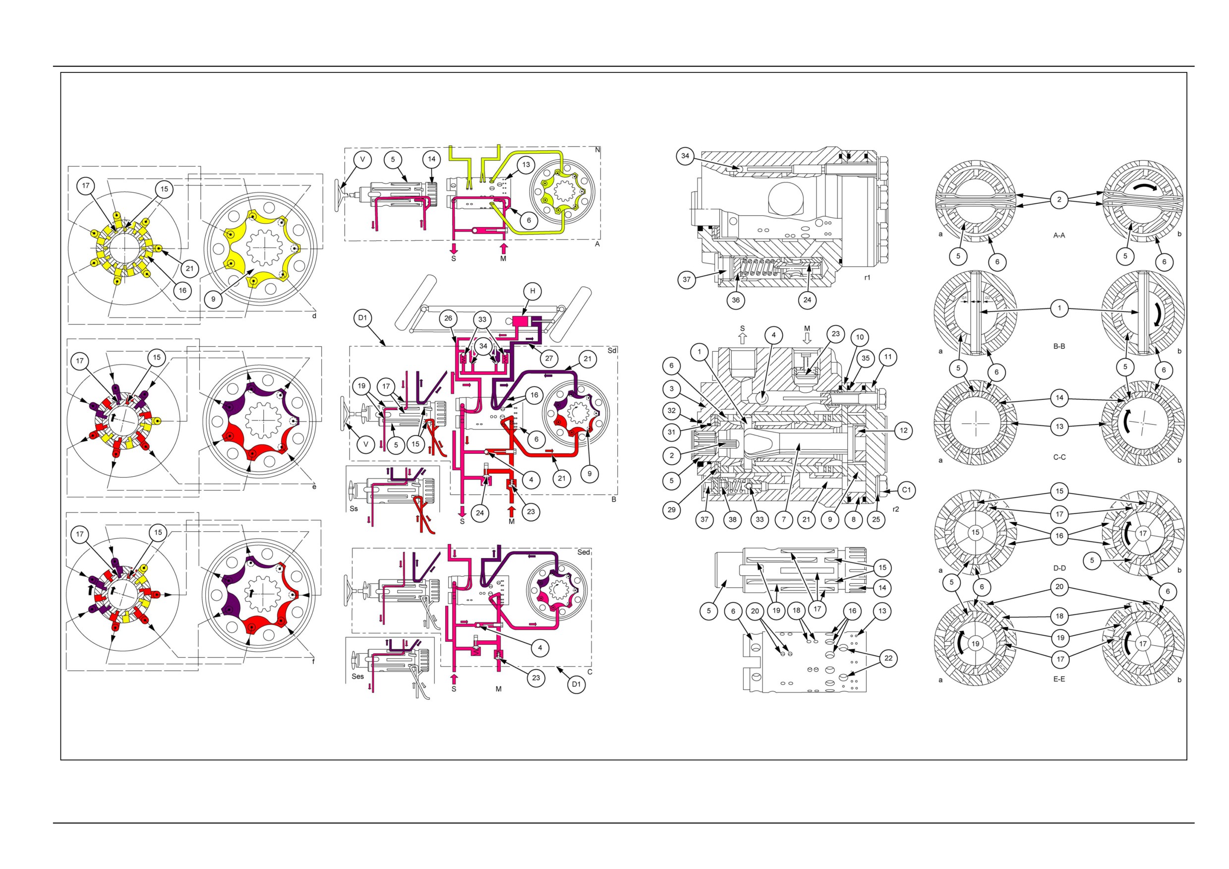
Straight - ahead driving ( A, a, d)
With steering wheel (V) stationary, rotary valve (5) takes neutral position relative to sleeve (6). This position is main-
tained through the action of springs (2), (see figure 2 section A-A) and the following conditions exist:
• Pin (1), (see figure 2 section B-B) is central in the valve (5) aperture.
• Ports (13) and (14) are in alignment (see figure 2 section C-C) and the oil pressure from pump (P) is returned to
tank.
• Passages (15), (17) and (19) on the valve (see figure 2 sections D-D and E-E) are off register relative to ports (16),
(18) and (20) on the sleeve (i.e. all ports in communication with the power cylinder remain closed).
Right-hand side steer ( B, Sd, b, e, f)
Upon turning steering wheel (V) clockwise, springs (2), (see figure 2 section A-A) deflect allowing valve (5) to rotate
relative to sleeve (6) until gap (G), (see figure 2 section B-B) is taken up.
Thus:
• Ports (13) and (14), (see figure 2 section C-C) go out of alignment to discontinue oil return.
• Six passages (15), (see figure 2 section D-D) line up with an equal number of ports (16) connected instant by instant
with the rotor recesses during the inlet phase.
• Six pressure passages (17), (see figure 2 section E-E) line up with ports (18) communicating with the power cylin-
der. Moreover, the oil pressure passages communicate with the remaining ports (16), (see figure 2 section D-D)
connected instant by instant with the rotor recesses during the actuation phase.
• Six exhaust passages (19) line up with ports (20), (see figure 2 section E-E) communicating with the power cylinder.
Once the gap (G) is eliminated valve (5) positively transmits steering wheel input to both sleeve (6) and rotor (9)
through pin (1) and shaft (7). Diagrams (e and f) show the principle of operation at start of right-hand side steer and
after a certain amount of wheel rotation.
The flow of oil pressure from pump to rotor during inlet, and from rotor to power cylinder line during the power actuation
phase, is provided instant by instant.
Left-hand side steer ( B, Ss)
Upon turning the steering wheel anti-clockwise, a reversal of the above sequence is obtained and delivery passages
(17), (see figure 2 section E-E) supply ports (20) to bring about left-hand side steering.
Emergency hydraulic steer ( C, Sed, Ses)
Steering is possible even in cases of loss of hydraulic pressure. Upon turning the steering wheel, valve (5) takes up
the normal operating position, whilst the rotor functions as a hand pump directing oil pressure to the power cylinder.
Check valve (4) opens, thereby permitting the flow of oil from tank to rotor by-passing the pump. Valve (23) remains
closed preventing leakage in connecting line between pump and control unit.
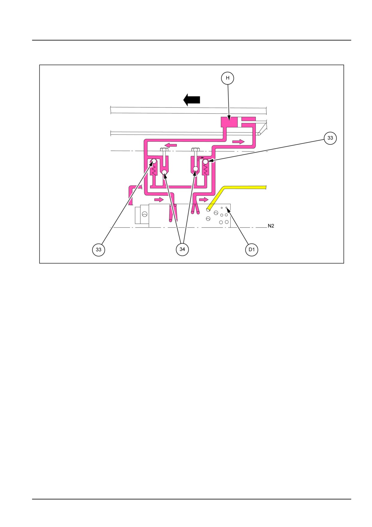
Power cylinder safety and make-up valves (N2)
As of safety valves open (33), pressure created by piston (H) is exhausted in one cylinder chamber under the action
of strong external stress on wheels. Simultaneously, vacuum in the opposite chamber is compensated by oil flow
through the opening of the associated make up valve (34). Pressure in one cylinder chamber deriving from small
external stress which are not sufficient to open cylinder safety valve, is exhausted through normal leakage past control
valve (D), while vacuum in the opposite chamber is compensated through make-up (34), as shown in detail N2, for
DANFOSS OSPC 100 control valve.
41.1 [41.101] / 8
Steering - Steering control
Operation of the above valves eliminates continuous steering wheel correction and prevents front wheel shimmy,
hydraulic circuit failure and damage to the steering linkage.
GNIL14TR04489FB
3
41.1 [41.101] / 9
Steering - Steering control
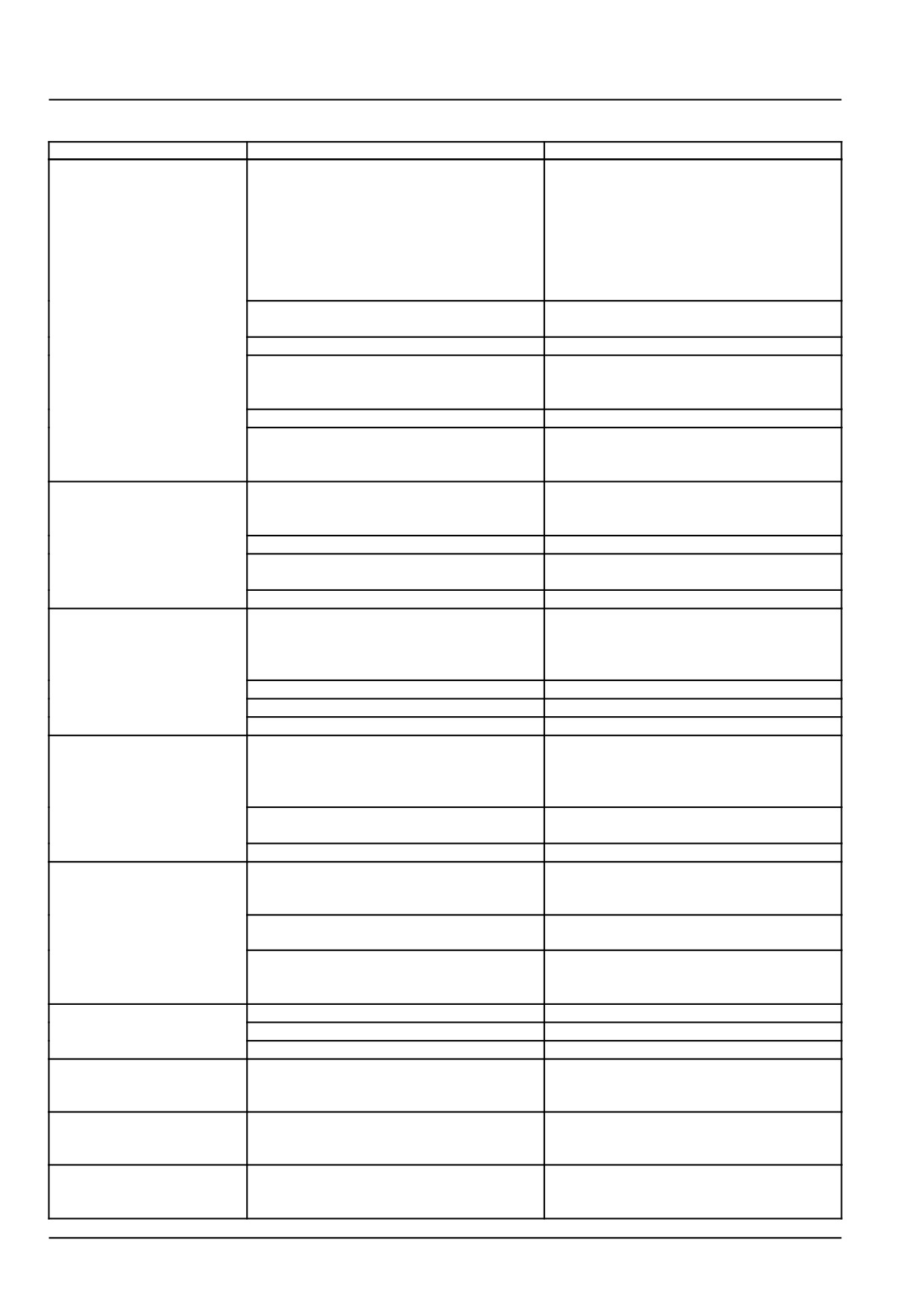
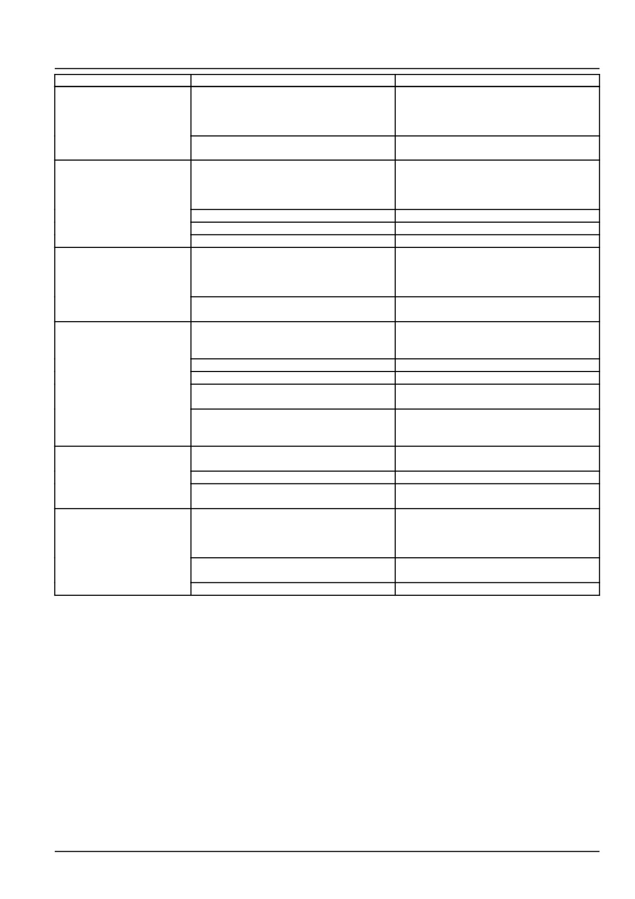
Steering control - Troubleshooting
Problem
Possible Cause
Correction
Steering wheel is heavy
No or insufficient oil pressure
to turn
a) Pump does not run
Start up pump (loose V-belt)
b) Pump defective
Repair or replace pump
c) Pump runs in the wrong
Correct direction of rotation of pump or re-
the direction
place pump
d) Pump is worn out
Replace pump
e) Pump is under dimensioned
Install a larger pump (examine pressure
need and flow)
Pressure relief valve is stuck in open posi-
Repair or clean pressure relief valve. Ad-
tion or setting pressure is too low
just the valve to the correct pressure
Priority valve is stuck in open position
Repair or clean the priority valve
Too much friction in the mechanical parts of
Lubricate bearings and joints of steering
the vehicle
gear or repair if necessary. Check steer-
ing column installation
Emergency steering balls missing
Install new balls
Combination: Downstream system + steer-
Change cylinder type (through going piston
ing unit with suction valve and differential
rod). If necessary use two differential cylin-
cylinder are inexpedient
ders
Hard point when starting
Spring force in priority valve too weak
Replace spring by a stronger one ( 4 bar
to turn the steering wheel
(58 psi)
,
7 bar
(102 psi) and
10 bar
(145 psi))
Air in LS and /or PP pipes
Bleed LS and PP pipes
Clogged orifices in LS or PP side priority
Clean orifices in spool and in connecting
valve
plugs for LS and PP
Oil is too thick (cold)
Let motor run until oil is warm
Regular adjustments of
Leaf spring without spring force or broken
Replace leaf springs
the steering wheel are
necessary (“snake-like
driving”)
Spring in double shock valve broken
Replace shock valve
Gear wheel set worn
Replace gear wheel set
Cylinder seized or piston seals worn
Replace defective parts
Neutral position of
Steering Column and steering unit out of
Align the steering column with steering unit
steering wheel cannot
line
be obtained, i.e. there is a
tendency of “Motoring”
Too little or no play between steering col-
Adjust the play and, if necessary, shorten
umn and steering unit input shaft
the splines journal.
Pinching between inner and outer spools
Contact your authorised NEW HOLLAND
“Motoring” effect. The
Leaf springs are stuck or broken and have
Replace leaf springs
steering wheel can turn
therefore reduced spring force
on its own
Inner and outer spools pinch, possible due
Clean steering unit or contact your NEW
to dirt
HOLLAND dealer
Return pressure in connection with the
Reduce return pressure, change cylinder
reaction between differential cylinder and
type or use a non-reaction control unit
steering unit too high
Backlash
Cardan shaft fork worn or broken
Replace cardan shaft
Leaf springs without spring force or broken
Replace leaf springs
Worn splines on the steering column
Replace steering column
“Kick-back” in steering
Fault in the system
Contact your authorised NEW HOLLAND
wheel from system. Kicks
from wheels
Heavy kick-back in
Wrong setting of cardan shaft and gear
Correct setting as shown in service manual
steering wheel in both
wheel set
directions
Turning the steering
Hydraulic hoses for the steering cylinders
Reverse the hoses
wheel activates the
have been switched around
steered wheels opposite
41.1 [41.101] / 10
Steering - Steering control
Problem
Possible Cause
Correction
“Shiny” - effect. The
Air in the steering cylinder
Bleed cylinder. Find and remove the rea-
steered wheels vibrate.
son for air collection
(Rough tread on tires
gives vibrations)
Mechanical connections or wheel bearings
Replace worn parts
worn
Steering wheel can be
Oil is needed in the tank
Fill with clean oil and bleed the system
turned the whole time
without the steered
wheels moving
Steering cylinder worn
Replace or repair cylinder
Gear wheel set worn
Replace gear wheel set
Spacer across cardan shaft forgotten
Install spacer
Steering wheel can be
One or both anti-cavitation valves are leaky
Clean or replace defect or missing valves
turned slowly in one or
or are missing in OSPC or OVP/OVR
both directions without
the steered wheels turning
One or both shock valves are leaky or are
Clean or replace defective or missing
missing in OS PC or OVP/OVR
valves
Steering is too slow and
Insufficient oil supply to steering unit, pump
Replace pump or increase number of revo-
heavy when trying to turn
defective or number of revolutions too low
lutions
quickly
Relief valve setting too low
Adjust valve to correct setting
Relief valve sticking owing to dirt
Clean the valve
Spool in priority valve sticking owing to dirt
Clean the valve, check that spool moves
easily without spring
Too weak spring in priority valve
Replace spring by a stronger (There are 3
sizes:
4 bar (58 psi), 7 bar (102 psi) and
10 bar (145 psi)
Too little steering force
Pump pressure too low
Correct pump pressure
(possibly to one side only)
Too little steering cylinder
Fit a larger cylinder
Piston rod area of the differential cylinder
Fit cylinder with thinner piston rod or 2 dif-
too large compared with piston diameter
ferential cylinders
Leakage at either
Shaft defective
Replace shaft seal
input shaft, end cover,
gear-wheel set, housing
or top part
Screws loose
Tighten screws Torque 3-3, t daNm or
steering unit (2, 5-3 daNm)
Washers or O-rings defective
Replace washers and O-rings
41.1 [41.101] / 11
Index
Steering - 41
Steering control - 101
Steering control - Overview - Hydrostatic steering
4
Steering control - Special tools
3
Steering control - Troubleshooting
10
41.1 [41.101] / 12
Steering - 41
Hydraulic control components - 200
Workmaster™ 50
Workmaster™ 60
Workmaster™ 70
41.2 [41.200] / 1
Contents
Steering - 41
Hydraulic control components - 200
SERVICE
Hydraulic steering oil reservoir
Remove
3
Power steering control valve
Remove
4
Disassemble
5
Cleaning
9
Inspect
10
Lubricate
11
Assemble
12
Install
23
Steering circuit relief valve
Pressure test
24
Adjust
25
41.2 [41.200] / 2
Steering - Hydraulic control components
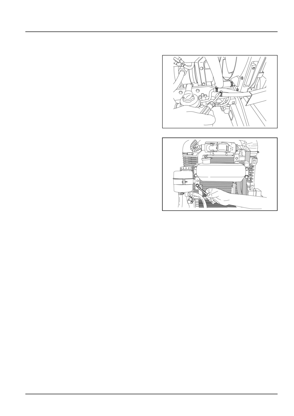
Hydraulic steering oil reservoir - Remove
1. Lift the front hood.
2. Disconnect the hoses from the steering oil reservoir.
GNIL14TR00758AA
1
3. Loosen the bolts and remove the steering oil reservoir.
GNIL14TR00759AA
2
41.2 [41.200] / 3
Steering - Hydraulic control components
Power steering control valve - Remove
1.
Position the tractor on a hard level surface and apply
the parking brake.
WARNING
Avoid injury!
Handle all parts carefully. Do not place your
hands or fingers between parts. Use Personal
Protective Equipment (PPE) as indicated in this
manual, including protective goggles, gloves,
and safety footwear.
Failure to comply could result in death or seri-
ous injury.
W0208A
2.
To gain access to the steering motor:
• Remove tractor rear hood
• Remove fuel tank
For removal procedure, please refer to Engine section.
3.
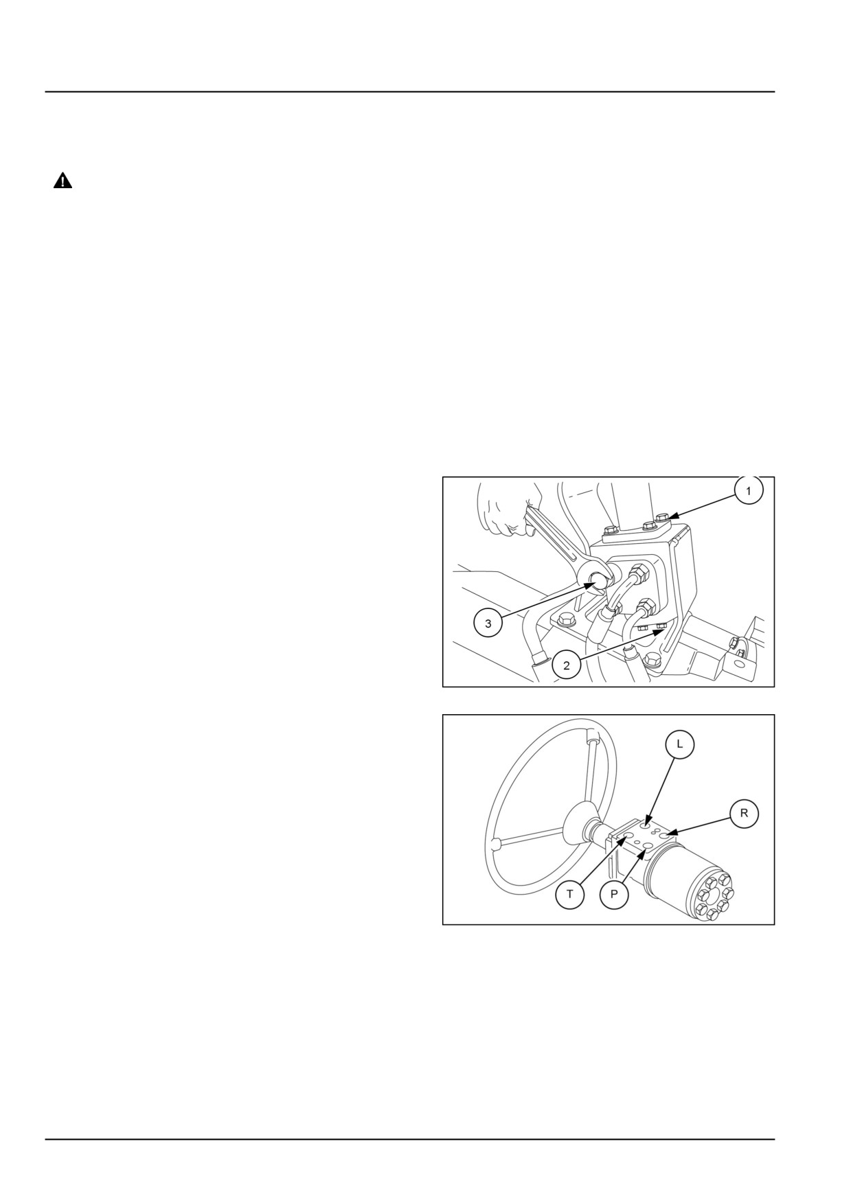
1. Remove the four bolts (1) at the base of the steering
column.
2. Slide out the steering motor from the steering col-
umn.
3. Remove bolts (2) from bracket to take out starting
motor.
4 Disconnect the four steering pipes (3).
GNIL14TR00740AA
1
Disconnect the four supply / return tubes and O-ring
seals from the steering motor
2. Cap the ends of the tubes and steering motor to
prevent entry of foreign particles.
T - To tank
P - From pump
L - Left port
R - Right port
GNIL14TR04490AB
2
41.2 [41.200] / 4
Steering - Hydraulic control components
Power steering control valve - Disassemble
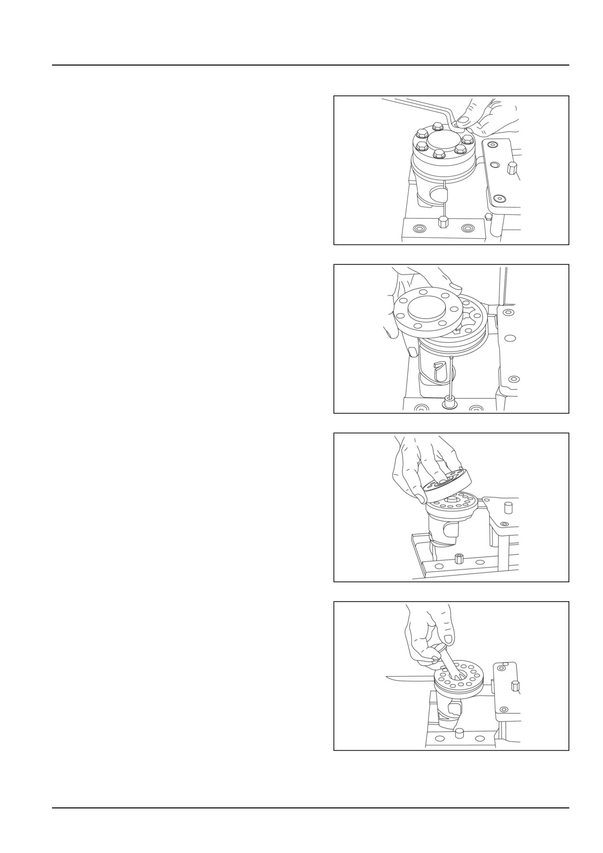
1. Hold the steering securely in a vice.
2. Remove the end cover bolts (6 plus one special screw).
GNIL14TR04492AA
1
3. Remove the end cover, sideways.
GNIL14TR04493AA
2
4. Lift the gear wheel set (with spacer fitted) off the unit.
Take out the two O-rings.
GNIL14TR04494AA
3
5. Remove cardan shaft.
GNIL14TR04495AA
4
41.2 [41.200] / 5
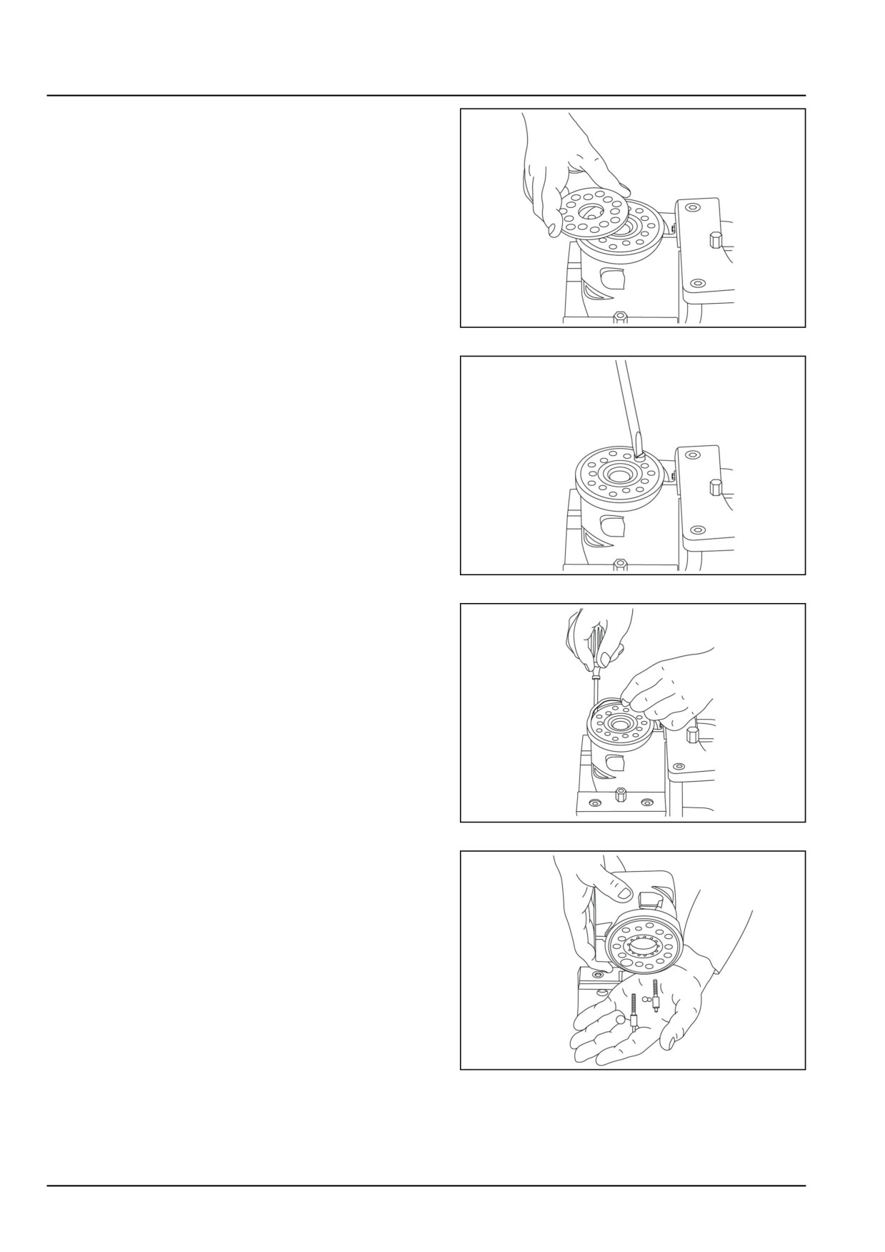
Steering - Hydraulic control components
6. Remove distributor plate.
GNIL14TR04496AA
5
7. Screw out the threaded bush over the check valve.
GNIL14TR04497AA
6
8. Remove O-ring.
GNIL14TR04498AA
7
9. Shake out the check valve ball and suction valve pins
and balls.
NOTE: Replace pins prior to the reassembly.
GNIL14TR04499AA
8
41.2 [41.200] / 6
Steering - Hydraulic control components
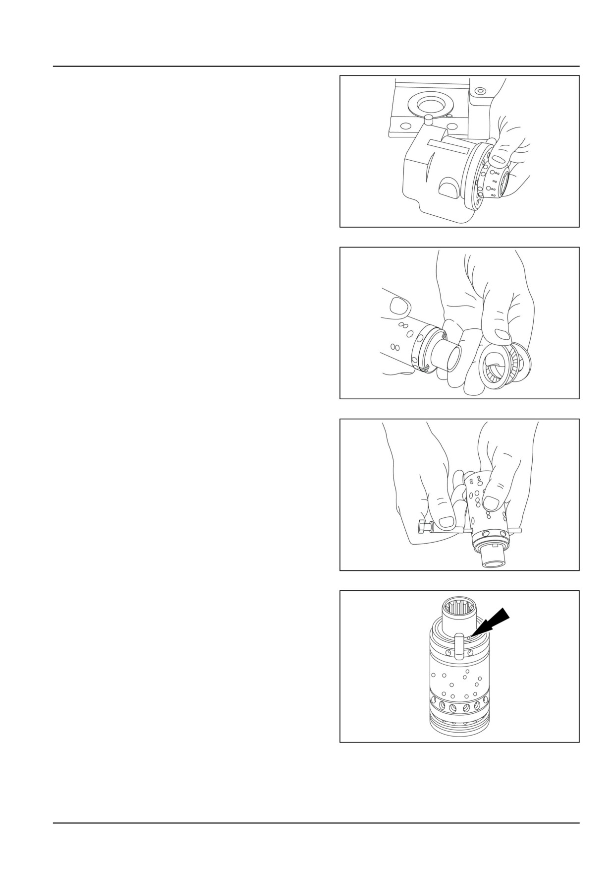
10. Take care to keep the cross pin in the sleeve and spool
horizontal. The pin can be seen through the open end
of the spool. Press the spool inwards and the sleeve,
ring, bearing races and needle bearing will be pushed
out of the housing together.
GNIL14TR04500AA
9
11. Take ring, bearing races and needle bearing from
sleeve and spool. The outer (thin) bearing race can
sometimes “stick” in the housing, therefore check that
it has come out.
GNIL14TR04501AA
10
12. Press out the cross pin. Use the special screw from
the end cover.
GNIL14TR04502AA
11
NOTE: A small mark has been made with pumice stone on
both spool and sleeve close to one of the slots for the neu-
tral position springs (see figure). If the mark is not visible,
remember to leave a mark of your own on sleeve and spool
before the neutral position springs are dismantled.
GNIL14TR04503AA
12
41.2 [41.200] / 7
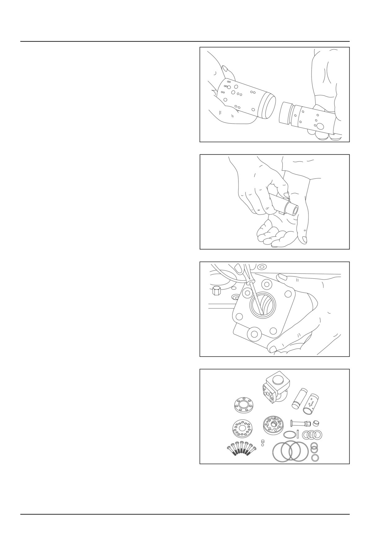
Steering - Hydraulic control components
13. Carefully press the spool out of the sleeve.
GNIL14TR04504AA
13
14. Press the neutral position springs out of their slots in
the spool.
GNIL14TR04505AA
14
15. Remove dust seal and O-ring /kin-ring /roto glyd.
GNIL14TR04506AA
15
16. The steering unit OSPB is now completely dismantled.
GNIL14TR04507AA
16
41.2 [41.200] / 8
Steering - Hydraulic control components
Power steering control valve - Cleaning
Clean all parts carefully in Shellsoi K or something sim-
ilar.
41.2 [41.200] / 9