New Holland Tractor Workmaster 50 / Workmaster 60 / Workmaster 70 / Tier 4B (final). SERVICE MANUAL - page 19

Electrical systems - FAULT CODES
From
To
Value
X-9008 pin 2
Chassis ground
There should be no continuity.
X-9008 pin 2
X-9008 pin 1
There should be no continuity.
X-9008 pin 2
X-9008 pin 3
There should be no continuity.
X-9001 pin A28
All pins in connector X-9001
There should be no continuity.
A. If there is no continuity, leave connector X-9008 disconnected and continue to Step 5.
B. If there is continuity, there is a a short circuit in the camshaft position sensor B-9017 wiring. Locate and repair
the broken conductor.
5. Replace the camshaft position sensor B-9017.
Use the Electronic Service Tool (EST) to verify the status of this fault, DTC 143-Min - Camshaft sensor failure.
A. If the fault has been resolved, return the machine to service.
B. If the fault has not been resolved, check the ECU A-9000 for the appropriate software and re-flash, if necessary.
6. Visually inspect the relevant harnesses and connectors for damage, bent or dislocated pins, corroded terminals,
or broken wires. Verify that the connectors are fully installed. Flex the harnesses involved to reveal intermittent
breaks or shorts in the wiring concerned. Operate the machine while you monitor the display.
A. If you find damage or the display indicates other than normal display readings, then repair the damage discov-
ered during the inspection or locate and repair the other than normal display condition and verify that the error
has been resolved.
B. If you do not find damage and the display indicates only normal readings, then erase the fault code and continue
operation.
Wiring harnesses - Electrical schematic sheet 03 - Engine sensors and fuel injection (engine schematics)
(55.100.DP-C.20.E.03)
45
Electrical systems - FAULT CODES
DTC 144-03-Compared camshaft and crankshaft speed sensor
values are not plausible
Control Module : ECU
Context:
The Engine Control Unit (ECU) A-9000 monitors the camshaft position sensor B-9017 and the crankshaft position
sensor B-9007 characteristics for angle, speed determination, signal plausibility, and quality. If the ECU A-9000 de-
termines that the offset between the crankshaft signal and the expected camshaft first edge is less or greater than
10.00 ° for longer than four consecutive cycles, this fault will occur.
Possible failure modes:
1. Faulty camshaft position sensor B-9017, improperly mounted or not fully seated.
2. Faulty crankshaft position sensor B-9007, improperly mounted or not fully seated.
3. Faulty camshaft tone wheel, loose or damaged.
4. Faulty crankshaft tone wheel, loose or damaged.
5. Faulty engine timing, incorrectly timed.
6. Faulty ECU A-9000, software.
46
Electrical systems - FAULT CODES
DTC 151-03-Fuel rail pressure has exceeded maximum positive
deviation limits
Control Module : ECU
NOTE: If the Pressure Relief Valve (PRV) is replaced, it is necessary to perform the Replacement of the Rail Pressure
Relief Valve (PRV) - Reset ECU Data with the Electronic Service Tool (EST) before you return the machine to service.
See Common rail Relief valve - Configure - Reset ECU data (10.218), if necessary.
NOTE: If the rail pressure sensor B-9004 is replaced, it is necessary to perform the Replacement of the Rail Pressure
sensor - Reset ECU Data with the Electronic Service Tool (EST) before you return the machine to service. See
Common rail pressure sensor - Configure - Reset ECU data (Rail pressure sensor) (55.010), if necessary.
Context:
The Engine Control Unit (ECU) A-9000 monitors fuel rail pressure. If the measured rail pressure is lower than the de-
sired pressure by 100 bar (1450 psi) depending on engine speed, this fault will occur. For more information regarding
fuel system troubleshooting, see Fuel injection system - Troubleshooting (10.218).
Cause:
The ECU A-9000 has determined that the measured rail pressure is 100 bar (1450 psi) lower than desired fuel pres-
sure based on engine speed.
Possible failure modes:
1. Faulty fuel metering unit Y-9000, internal failure.
2. Faulty charge gear pump, low efficiency.
3. Faulty fuel filters, clogged.
4. Faulty low pressure fuel supply lines, clogged or damaged.
5. Faulty high pressure fuel supply lines, clogged or damaged.
6. Faulty Pressure Relief Valve (PRV), leakage.
7. Faulty high pressure fuel pump, low efficiency.
8. Faulty fuel injectors, worn, clogged or internal leakage.
9. Faulty rail pressure sensor B-9004, drifted or leaking.
10. Faulty ECU A-9000, software.
47
Electrical systems - FAULT CODES
DTC 153-03-Fuel rail pressure has exceeded maximum negative
deviation limits
Control Module : ECU
NOTE: If the Pressure Relief Valve (PRV) is replaced, it is necessary to perform the Replacement of the Rail Pressure
Relief Valve (PRV) - Reset ECU Data with the Electronic Service Tool (EST) before you return the machine to service.
See Common rail Relief valve - Configure - Reset ECU data (10.218), if necessary.
NOTE: If the rail pressure sensor B-9004 is replaced, it is necessary to perform the Replacement of the Rail Pressure
sensor - Reset ECU Data with the Electronic Service Tool (EST) before you return the machine to service. See
Common rail pressure sensor - Configure - Reset ECU data (Rail pressure sensor) (55.010), if necessary.
Context:
The Engine Control Unit (ECU) A-9000 monitors fuel rail pressure. If the ECU A-9000 determines that fuel pressure is
higher than the desired fuel pressure, depending on engine speed, this fault will occur. For more information regarding
fuel system troubleshooting, see Fuel injection system - Troubleshooting (10.218).
Cause:
The ECU A-9000 has determined that the fuel rail pressure is higher than desired based on engine speed.
Possible failure modes:
1. Faulty fuel metering unit Y-9000 wiring, broken or poor connections.
2. Faulty fuel metering unit Y-9000, stuck open.
3. Faulty fuel back-flow, clogged or damaged.
4. Faulty Pressure Relief Valve (PRV), stuck or blocked.
5. Faulty rail pressure sensor B-9004, drifted.
6. Faulty high pressure pump.
7. Faulty ECU A-9000, software.
Solution:
1. Verify fault is present and active.
Use the Electronic Service Tool (EST) to check the status of this fault.
A. If the fault is present and active, continue with Step 2.
B. If the fault is no longer present or in an inactive state, the fault may be intermittent and not currently active,
continue to Step 5.
2. Check for other fault codes related to the fuel injection system.
A. If other fault codes are not present, continue with Step
3.
B. If other fault codes are present, resolve them first.
3. Check the condition of the Y-9000 connector X-9007.
Disconnect the engine (EN) harness from the Y-9000 at connector X-9007.
Inspect the connector X-9007 contacts for corrosion, damage and proper connection.
A. If the condition of the X-9007 contacts are good, leave the X-9007 disconnected and continue to Step 4.
B. If the X-9007 is faulty, refer to the appropriate service manual to repair or replace the engine (EN) harness as
necessary.
4. Check the Y-9000 for an internal failure.
48
Electrical systems - FAULT CODES
Use a multimeter to perform the following resistance check:
From
To
Value
X-9007 pin 1
X-9007 pin 2
There should be between 2.8 - 3.2 Ω.
A. If the value is in the specified range, see Fuel injection system - Troubleshooting (10.218) to diagnose the
fuel injection system.
B. If the value is not in the specified range, the Y-9000 has failed internally. Replace the Y-9000 then refer to
Pressure regulating valve - Configure - Reset ECU data (10.218) if necessary, to perform the Replacement
of the Rail Pressure Metering Unit - Reset ECU Data.
5. Visually inspect the relevant harnesses and connectors for damage, bent or dislocated pins, corroded terminals,
or broken wires. Verify that the connectors are fully installed. Flex the harnesses involved to reveal intermittent
breaks or shorts in the wiring concerned. Operate the machine while you monitor the display.
A. If you find damage or the display indicates other than normal display readings, then repair the damage discov-
ered during the inspection or locate and repair the other than normal display condition and verify that the error
has been resolved.
B. If you do not find damage and the display indicates only normal readings, then erase the fault code and continue
operation.
Wiring harnesses - Electrical schematic sheet 03 (55.100)
49
Electrical systems - FAULT CODES
DTC 154-03-Fuel rail pressure has dropped below the minimum limit
Control Module : ECU
NOTE: If the Pressure Relief Valve (PRV) is replaced, it is necessary to perform the Replacement of the Rail Pressure
Relief Valve (PRV) - Reset ECU Data with the Electronic Service Tool (EST) before you return the machine to service.
See Common rail Relief valve - Configure - Reset ECU data (10.218), if necessary.
NOTE: If the rail pressure sensor B-9004 is replaced, it is necessary to perform the Replacement of the Rail Pressure
sensor - Reset ECU Data with the Electronic Service Tool (EST) before you return the machine to service. See
Common rail pressure sensor - Configure - Reset ECU data (Rail pressure sensor) (55.010), if necessary.
Context:
The Engine Control Unit (ECU) A-9000 monitors fuel rail pressure using the rail pressure sensor B-9004. If the ECU
A-9000 determines that the measured rail pressure is less than a dependent engine speed value, this fault will occur.
Other active faults may have caused this fault to occur. For more information regarding fuel system troubleshooting,
see Fuel injection system - Troubleshooting (10.218).
Cause:
The ECU A-9000 has determined that the measured rail pressure is less than a dependent engine speed value.
Possible failure modes:
1. Faulty fuel filters, clogged.
2. Faulty low pressure fuel lines, clogged or damaged.
3. Faulty high pressure fuel lines, clogged or damaged.
4. Faulty electric fuel pump (if equipped).
5. Faulty charge gear pump, low efficiency.
6. Faulty high pressure pump, low efficiency or excessive leak-off.
7. Faulty fuel injectors, excessive or leaking internally.
8. Faulty Pressure Relief Valve (PRV), leaking or stuck open.
9. Faulty rail pressure sensor B-9004 or sensor leaking.
10. Faulty fuel metering unit Y-9000
11. Faulty ECU A-9000, software.
50
Electrical systems - FAULT CODES
DTC 155-03-Fuel rail pressure has exceeded maximum limit
Control Module : ECU
NOTE: If the Pressure Relief Valve (PRV) is replaced, it is necessary to perform the Replacement of the Rail Pressure
Relief Valve (PRV) - Reset ECU Data with the Electronic Service Tool (EST) before you return the machine to service.
See Common rail Relief valve - Configure - Reset ECU data (10.218), if necessary.
NOTE: If the rail pressure sensor B-9004 is replaced, it is necessary to perform the Replacement of the Rail Pressure
sensor - Reset ECU Data with the Electronic Service Tool (EST) before you return the machine to service. See
Common rail pressure sensor - Configure - Reset ECU data (Rail pressure sensor) (55.010), if necessary.
Context:
The Engine Control Unit (ECU) A-9000 monitors fuel rail pressure using the rail pressure sensor B-9004. If the ECU
A-9000 determines that the measured rail pressure is greater than desired by more than a dependent engine speed
value, this fault will occur. For more information regarding fuel system troubleshooting, see Fuel injection system -
Troubleshooting (10.218).
Cause:
The ECU A-9000 has determined that the measured rail pressure is greater than desired by more than a dependent
engine speed value.
Possible failure modes:
1. Faulty fuel metering unit Y-9000 wiring, broken or poor connections.
2. Faulty fuel metering unit Y-9000, stuck open or internal failure.
3. Faulty fuel back-flow lines, blocked or damaged.
4. Faulty Pressure Relief Valve (PRV), stuck closed or mechanically unable to open.
5. Faulty high pressure pump, zero delivery throttle valve clogged.
6. Faulty rail pressure sensor B-9004, drifted signal.
7. Faulty ECU A-9000, software.
Solution:
1. Verify fault is present and active.
Use the Electronic Service Tool (EST) to check the status of this fault.
A. If the fault is present and active, continue with Step 2.
B. If the fault is no longer present or in an inactive state, the fault may be intermittent and not currently active,
continue to Step 5.
2. Check for other fault codes related to the fuel injection system.
A. If other fault codes are not present, continue with Step
3.
B. If other fault codes are present, resolve them first.
3. Check the condition of the Y-9000 connector X-9007.
Disconnect the engine (EN) harness from the Y-9000 at connector X-9007.
Inspect the connector X-9007 contacts for corrosion, damage and proper connection.
A. If the condition of the X-9007 contacts are good, leave the X-9007 disconnected and continue to Step 4.
B. If the X-9007 is faulty, refer to the appropriate service manual to repair or replace the engine (EN) harness as
necessary.
4. Check the Y-9000 for an internal failure.
51
Electrical systems - FAULT CODES
Use a multimeter to perform the following resistance check:
From
To
Value
X-9007 pin 1
X-9007 pin 2
There should be between 2.8 - 3.2 Ω
(2.8 - 3.2 Ω).
A. If the value is in the specified range, see Fuel injection system - Troubleshooting (10.218) to diagnose the
fuel injection system.
B. If the value is not in the specified range, the Y-9000 has failed internally. Replace the Y-9000 then refer to
Pressure regulating valve - Configure (10.218) if necessary, to perform the Replacement of the Rail Pressure
Metering Unit - Reset ECU Data.
5. Visually inspect the relevant harnesses and connectors for damage, bent or dislocated pins, corroded terminals,
or broken wires. Verify that the connectors are fully installed. Flex the harnesses involved to reveal intermittent
breaks or shorts in the wiring concerned. Operate the machine while you monitor the display.
A. If you find damage or the display indicates other than normal display readings, then repair the damage discov-
ered during the inspection or locate and repair the other than normal display condition and verify that the error
has been resolved.
B. If you do not find damage and the display indicates only normal readings, then erase the fault code and continue
operation.
Wiring harnesses - Electrical schematic sheet 03 (55.100)
52
Electrical systems - FAULT CODES
DTC 157-03-High pressure pump fuel delivery quantity in over run
exceeds a maximum threshold
Control Module : ECU
Context:
The Engine Control Unit (ECU) A-9000 monitors the high pressure fuel system for leakage during overrun. If the ECU
A-9000 detects that the high pressure pump quantity in overrun exceeds the expected threshold, this fault will occur.
Cause:
The ECU A-9000 has determined that the high pressure fuel pump quantity is higher than the expected fuel quantity
threshold.
Possible failure modes:
1. Faulty low pressure fuel system, clogged filter or leakage/blockage.
2. Faulty charge gear pump, low efficiency or line clogged/damaged.
3. Faulty electric fuel pump (if equipped).
4. Faulty fuel metering unit, unable to fully open.
5. Faulty high pressure pump, low efficiency.
6. Faulty fuel injectors, stuck open or internal leakage.
7. Faulty Pressure Relief Valve (PRV), leakage.
8. Faulty rail pressure sensor B-9004 drifted signal or leaking.
9. Faulty ECU A-9000, software.
53
Electrical systems - FAULT CODES
DTC 158-03-Fuel pump pressure has exceeded desired pressure
limits
Control Module : ECU
NOTE: If the Pressure Relief Valve (PRV) is replaced, it is necessary to perform the Replacement of the Rail Pressure
Relief Valve (PRV) - Reset ECU Data with the Electronic Service Tool (EST) before you return the machine to service.
See Common rail Relief valve - Configure - Reset ECU data (10.218), if necessary.
NOTE: If the rail pressure sensor B-9004 is replaced, it is necessary to perform the Replacement of the Rail Pressure
sensor - Reset ECU Data with the Electronic Service Tool (EST) before you return the machine to service. See
Common rail pressure sensor - Configure - Reset ECU data (Rail pressure sensor) (55.010), if necessary.
Context:
The Engine Control Unit (ECU) Y-9000 monitors fuel rail pressure. If the ECU A-9000 determines that the requested
fuel pressure can not be reached, a leakage in the fuel system is assumed and this fault will occur. For more infor-
mation regarding fuel system troubleshooting, see Fuel injection system - Troubleshooting (10.218).
Cause:
The ECU A-9000 has determined that a fuel system leakage is present.
Possible failure modes:
1. Faulty fuel filters, clogged.
2. Faulty low pressure fuel lines, clogged or damaged.
3. Faulty high pressure fuel lines, clogged or damaged.
4. Faulty electric fuel pump (if equipped).
5. Faulty charge gear pump, low efficiency.
6. Faulty high pressure pump, low efficiency or excessive leak-off.
7. Faulty fuel injectors, external or internal leakage.
8. Faulty Pressure Relief Valve (PRV), leaking or stuck open.
9. Faulty rail pressure sensor B-9004 or sensor leaking.
10. Faulty fuel metering unit Y-9000
11. Faulty ECU A-9000, software.
54
Electrical systems - FAULT CODES
DTC 159-02-Fuel metering unit has an open load error
Control Module : ECU
Context:
The Engine Control Unit (ECU) A-9000 monitors the fuel metering unit Y-9000 signal circuit. If the ECU A-9000 detects
an open load error in the fuel metering unit Y-9000 signal circuit, this fault will occur.
Cause:
There is open load detected in the fuel metering unit Y-9000 signal circuit.
Possible failure modes:
1. Faulty fuel metering unit Y-9000 wiring, open circuit.
2. Faulty fuel metering unit Y-9000, internal failure.
3. Faulty ECU A-9000, software.
Solution:
1.
Verify fault is present and active.
Use the Electronic Service Tool (EST) to check the status of this fault.
A. If the fault is present and active, continue with Step 2.
B. If the fault is no longer present or in an inactive state, the fault may be intermittent and not currently active.
Continue with Step 4.
2.
Test the fuel metering unit Y-9000 internal resistance.
Disconnect the engine harness (EN) from the fuel metering unit Y-9000 at connector X-9007.
Use a multimeter to measure the resistance on the fuel metering unit Y-9000 pins :
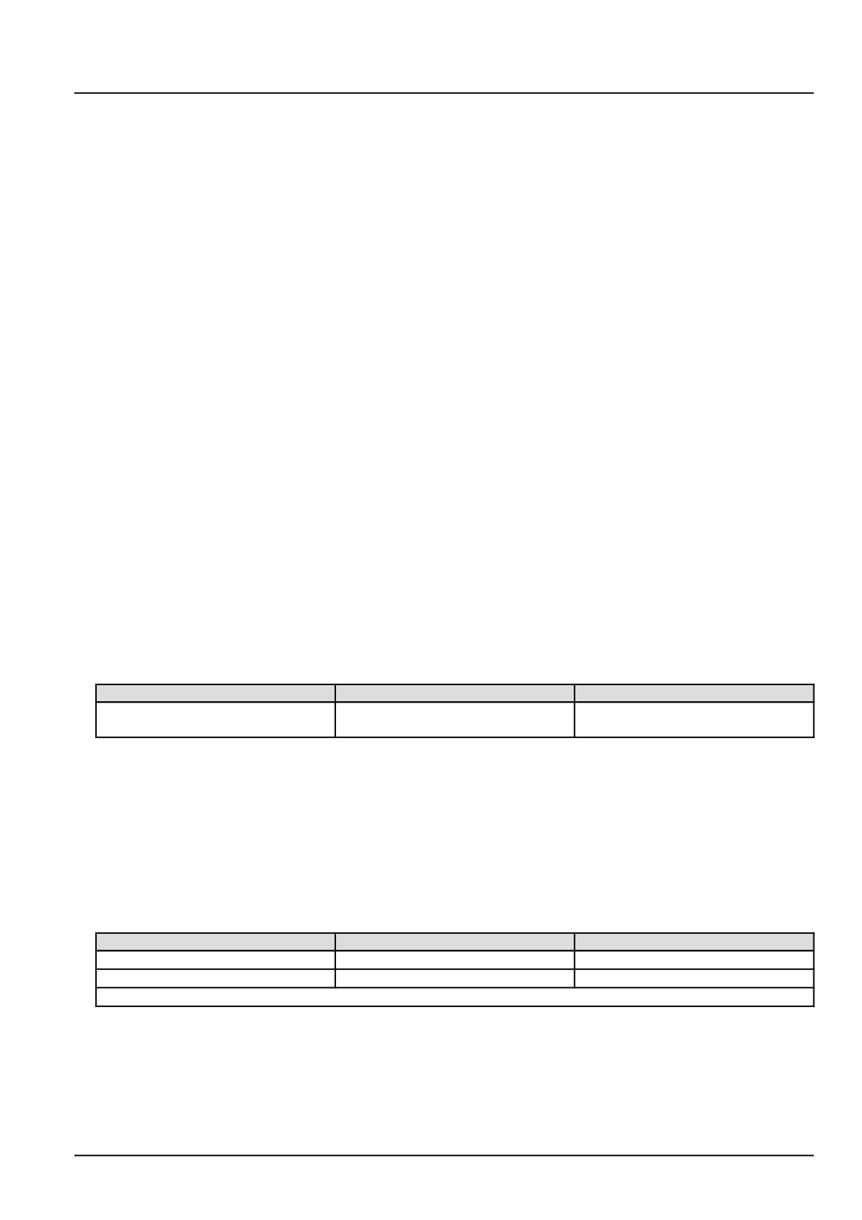
From
To
Value
X-9007 pin 1
X-9007 pin 2
There should be between 2.6 - 3.2 Ω
at approximately 20.0 °C (68.0 °F).
A. If there is between 2.6 - 3.2 Ω, leave connector X-9007 disconnected and continue to Step 3.
B. If there is not between 2.6 - 3.2 Ω, the fuel metering unit Y-9000 has failed. Replace the fuel metering unit
Y-9000.
3.
Check the fuel metering unit Y-9000 engine harness (EN) wiring for an open circuit.
Disconnect the engine harness (EN) from the ECU A-9000 at connector X-9001.
With the key in the OFF position, use a multimeter to perform the following continuity check on the engine harness
(EN) side :
From
To
Value
X-9007 pin 1
X-9001 pin A60
There should be continuity.
X-9007 pin 2
X-9001 pin A15
There should be continuity.
NOTE: Wiggle the harness during the check to promote an intermittent electrical connection.
A. If there is no continuity, there is an open circuit condition in the fuel metering unit Y-9000 engine harness (EN)
wiring. Locate and repair the broken conductor.
B. If there is continuity, check the ECU A-9000 for the appropriate software and re-flash, if necessary.
55
Electrical systems - FAULT CODES
4. Visually inspect the relevant harnesses and connectors for damage, bent or dislocated pins, corroded terminals,
or broken wires. Verify that the connectors are fully installed. Flex the harnesses involved to reveal intermittent
breaks or shorts in the wiring concerned. Operate the machine while you monitor the display.
A. If you find damage or the display indicates other than normal display readings, then repair the damage discov-
ered during the inspection or locate and repair the other than normal display condition and verify that the error
has been resolved.
B. If you do not find damage and the display indicates only normal readings, then erase the fault code and continue
operation.
Wiring harnesses - Electrical schematic sheet 03 - Engine sensors and fuel injection (engine schematics)
(55.100.DP-C.20.E.03)
56
Electrical systems - FAULT CODES
DTC 15D-03-PMCat Inducement less severe derating level
Control Module : ECU
Context:
The Engine Control Unit (ECU) monitors the Particulate Matter (PM) catalytic converter efficiency. If the ECU A-9000
detects an failure of efficiency, inducement will be triggered and this fault will occur. Other active faults may have
caused this fault to occur. This fault indicates the least severe level of inducement.
57
Electrical systems - FAULT CODES
DTC 161-02-Short circuit error of injector in cylinder 1
Control Module : ECU
Context:
The Engine Control Unit (ECU) A-9000 monitors the fuel injector power stages for a short circuit condition. If the ECU
A-9000 detects a short circuit condition in the injector number 1 Y-9001 circuit, this fault will occur.
Cause:
The ECU A-9000 has detected a short circuit in the fuel injector number 1 Y-9001 circuit.
Possible failure modes:
1. Faulty fuel injector number 1 Y-9001 wiring, short circuit.
2. Faulty fuel injector number 1 Y-9001, internal failure.
3. Faulty ECU A-9000, software.
Solution:
1.
Verify this fault code is still present and in an active state.
Use the Easy Engine software provided on the Electronic Service Tool (EST) to check the fault status and to
perform the cylinder cut-out test.
A. If the fault is still present and active, continue with Step 2.
B. If the fault is no longer present or is in an inactive state, the fault may be intermittent and not currently active.
Continue with Step 7.
2.
Check the fuel injector number 1 Y-9001 internal resistance.
Disconnect the engine harness (EN) from the fuel injector number 1 Y-9001 at connector X-9030 .
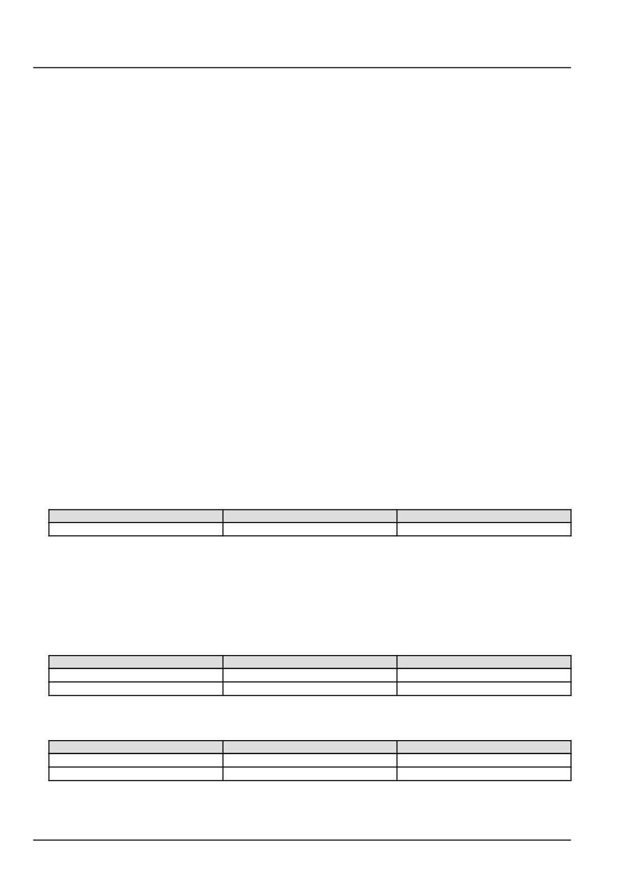
Use a multimeter to measure the resistance of fuel injector number 1 Y-9001 on the injector pins :
From
To
Value
X-9030 pin 1
X-9030 pin 2
There should be between .03 - .05 Ω
A. If there is between .03 - .05 Ω, leave connector X-9030 disconnected and continue to Step 3.
B. If the resistance is not between .03 - .05 Ω, fuel injector number 1 Y-9001 solenoid coil has failed. Replace
fuel injector number 1 Y-9001.
3.
Check the fuel injector number 1 Y-9001 engine harness (EN) wiring for a short to a voltage source.
With the key in the OFF position, use a multimeter to perform the following voltage check on the engine harness
(EN) side :
From
To
Value
X-9030 pin 1
Chassis ground
There should be no voltage.
X-9030 pin 2
Chassis ground
There should be no voltage.
With the key in the ON position, use a multimeter to perform the following voltage check on the engine harness
(EN) side :
From
To
Value
X-9030 pin 1
Chassis ground
There should be no voltage.
X-9030 pin 2
Chassis ground
There should be no voltage.
A. If there is no voltage, leave connector X-9030 disconnected and continue to Step 4.
58
Electrical systems - FAULT CODES
B. If there is voltage, there is a short to battery or switched battery in the fuel injector number 1 Y-9001 wiring in
the engine harness (EN). Use the appropriate service manual, if necessary, to locate and repair the shorted
conductor.
4.
Check the fuel injector number 1 Y-9001 engine harness (EN) wiring for a short to ground condition.
Disconnect the engine harness (EN) from the ECU A-9000 at connector X-9001.
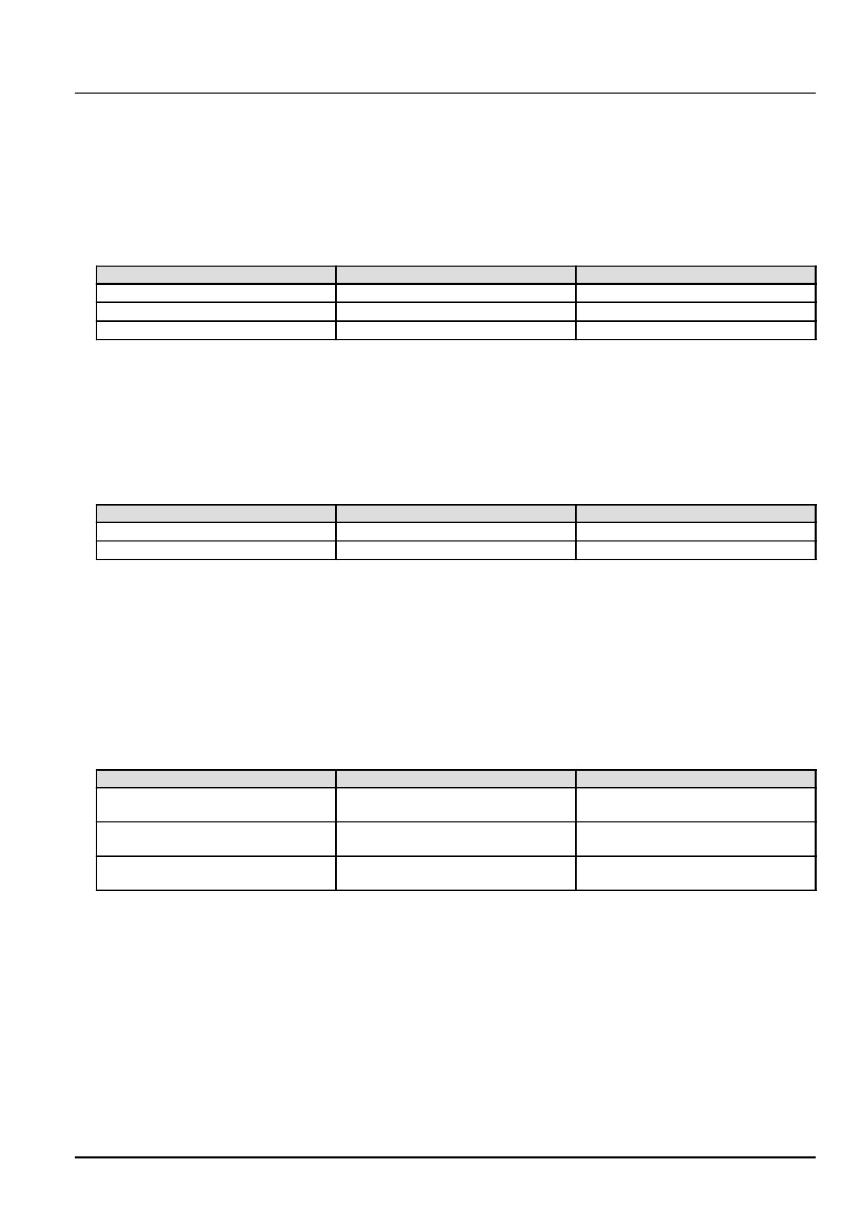
With the key in the OFF position, use a multimeter to perform the following continuity checks on the engine harness
(EN) side :
From
To
Value
X-9030 pin 1
X-9030 pin 2
There should be no continuity.
X-9030 pin 1
Chassis ground
There should be no continuity.
X-9030 pin 2
Chassis ground
There should be no continuity.
A. If there is no continuity, leave connector X-9001 and X-9030 disconnected. Continue to Step 5.
B. If there is continuity, there is a short circuit in the fuel injector number 1 Y-9001 wiring in the engine harness
(EN). Locate and repair the shorted conductor.
5.
Check the fuel injector number 1 Y-9001 engine harness (EN) wiring for a short circuit condition.
With the key in the OFF position, use a multimeter to perform the following continuity checks on engine harness
(EN) side :
From
To
Value
X-9001 pin A16
All pins in connector X-9001
There should be no continuity.
X-9001 pin A32
All pins in connector X-9001
There should be no continuity.
A. If there is continuity, there is a short circuit in the fuel injector number 1 Y-9001 wiring in the engine harness
(EN). Use the appropriate service manual, if necessary, to locate and repair the shorted conductor.
B. If there is no continuity, continue with Step 6.
6.
Check the ECU A-9000 voltage supply wiring.
Disconnect the vehicle harness (VE) from the ECU A-9000 at connector X-9102.
Place a jumper wire between X-9102 pin K28 and chassis ground. This will energize the main relay K-9102.
Use a multimeter to perform the following voltage checks on the engine harness (EN) side :
From
To
Value
X-9102 pin K01
X-9102 pin K02
There should be approximately
12.0 V.
X-9102 pin K03
X-9102 pin K04
There should be approximately
12.0 V.
X-9102 pin K05
X-9102 pin K06
There should be approximately
12.0 V.
A. If there is not approximately 12.0 V, there is a faulty ECU A-9000 voltage supply. Use the appropriate service
manual, if necessary, to locate and repair the failed conductor.
B. If there is approximately 12.0 V, check the ECU A-9000 for the appropriate software and re-flash, if necessary.
7.
Visually inspect the relevant harnesses and connectors for damage, bent or dislocated pins, corroded terminals,
or broken wires. Verify that the connectors are fully installed. Flex the harnesses involved to reveal intermittent
breaks or shorts in the wiring concerned. Operate the machine while you monitor the display.
A. If you find damage or the display indicates other than normal display readings, then repair the damage discov-
ered during the inspection or locate and repair the other than normal display condition and verify that the error
has been resolved.
B. If you do not find damage and the display indicates only normal readings, then erase the fault code and continue
operation.
59
Electrical systems - FAULT CODES
Wiring harnesses - Electrical schematic sheet 01 - Power distribution and glow plugs (engine schematics)
(55.100.DP-C.20.E.01)
Wiring harnesses - Electrical schematic sheet 02 - Engine Control Unit (ECU) power and after treatment
system (engine schematics) (55.100.DP-C.20.E.02)
Wiring harnesses - Electrical schematic sheet 03 - Engine sensors and fuel injection (engine schematics)
(55.100.DP-C.20.E.03)
60
Electrical systems - FAULT CODES
DTC 161-03-Short circuit of low side to high source of injector in
cylinder 1
Control Module : ECU
Context:
The Engine Control Unit (ECU) A-9000 monitors the fuel injector power stages for a short circuit condition. If the ECU
A-9000 detects a short circuit condition in the injector number 1 Y-9001 circuit, this fault will occur.
Cause:
The ECU A-9000 has detected a short circuit between the high side driver and low side driver of the fuel injector
number 1 Y-9001.
Possible failure modes:
1. Faulty fuel injector number 1 Y-9001 wiring, short circuit.
2. Faulty fuel injector number 1 Y-9001, internal failure.
3. Faulty ECU A-9000, software.
Solution:
1.
Verify this fault code is still present and in an active state.
Use the Easy Engine software provided on the Electronic Service Tool (EST) to check the fault status and to
perform the cylinder cut-out test.
A. If the fault is still present and active, continue with Step 2.
B. If the fault is no longer present or is in an inactive state, the fault may be intermittent and not currently active.
Continue with Step 6.
2.
Check the fuel injector number 1 Y-9001 internal resistance.
Disconnect the engine harness (EN) from the fuel injector number 1 Y-9001 at connector X-9030.
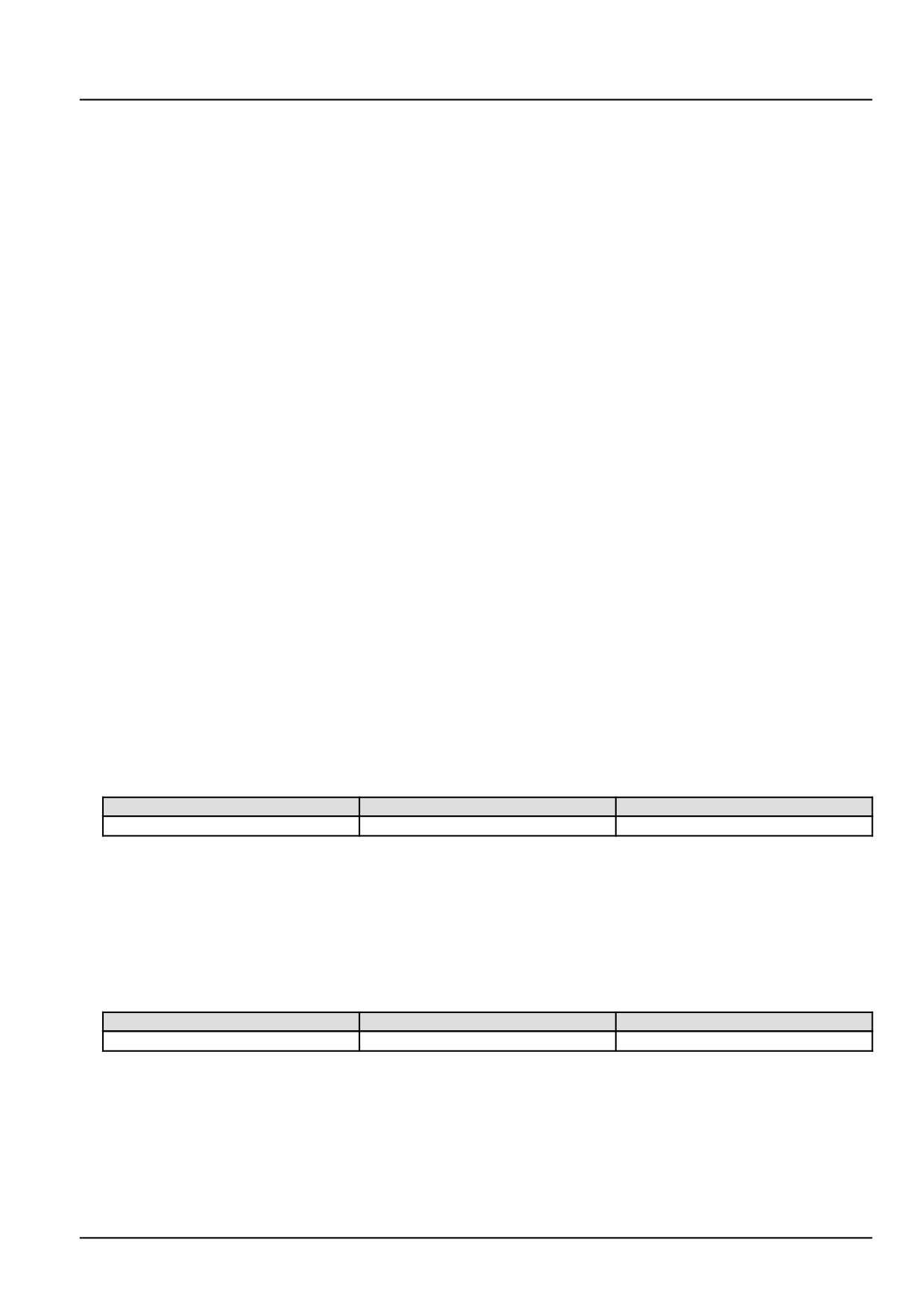
Use a multimeter to measure the resistance of fuel injector number 1 Y-9001 on the injector pins :
From
To
Value
X-9030 pin 1
X-9030 pin 2
There should be between .03 - .05 Ω
A. If there is between .03 - .05 Ω, leave connector X-9030 disconnected and continue to Step 3.
B. If the resistance is not between .03 - .05 Ω, fuel injector number 1 Y-9001 solenoid coil has failed. Replace
fuel injector number 1 Y-9001.
3.
Check the fuel injector number 1 Y-9001 injector harness (INJ) wiring for a short circuit condition.
With the key in the OFF position, use a multimeter to perform the following continuity check on the engine harness
(EN) side :
From
To
Value
X-9030 pin 1
X-9030 pin 2
There should be no continuity.
A. If there is no continuity, leave connector X-9030 disconnected and continue to Step 4.
B. If there is continuity, there is a short circuit in the fuel injector number 1 Y-9001 wiring in the engine harness
(EN) wiring. Locate and repair the shorted conductor.
4.
Check the fuel injector number 1 Y-9001 vehicle harness (VE) wiring for a short circuit condition.
Disconnect the engine harness (EN) from the ECU A-9000 at connector X-9001.
61
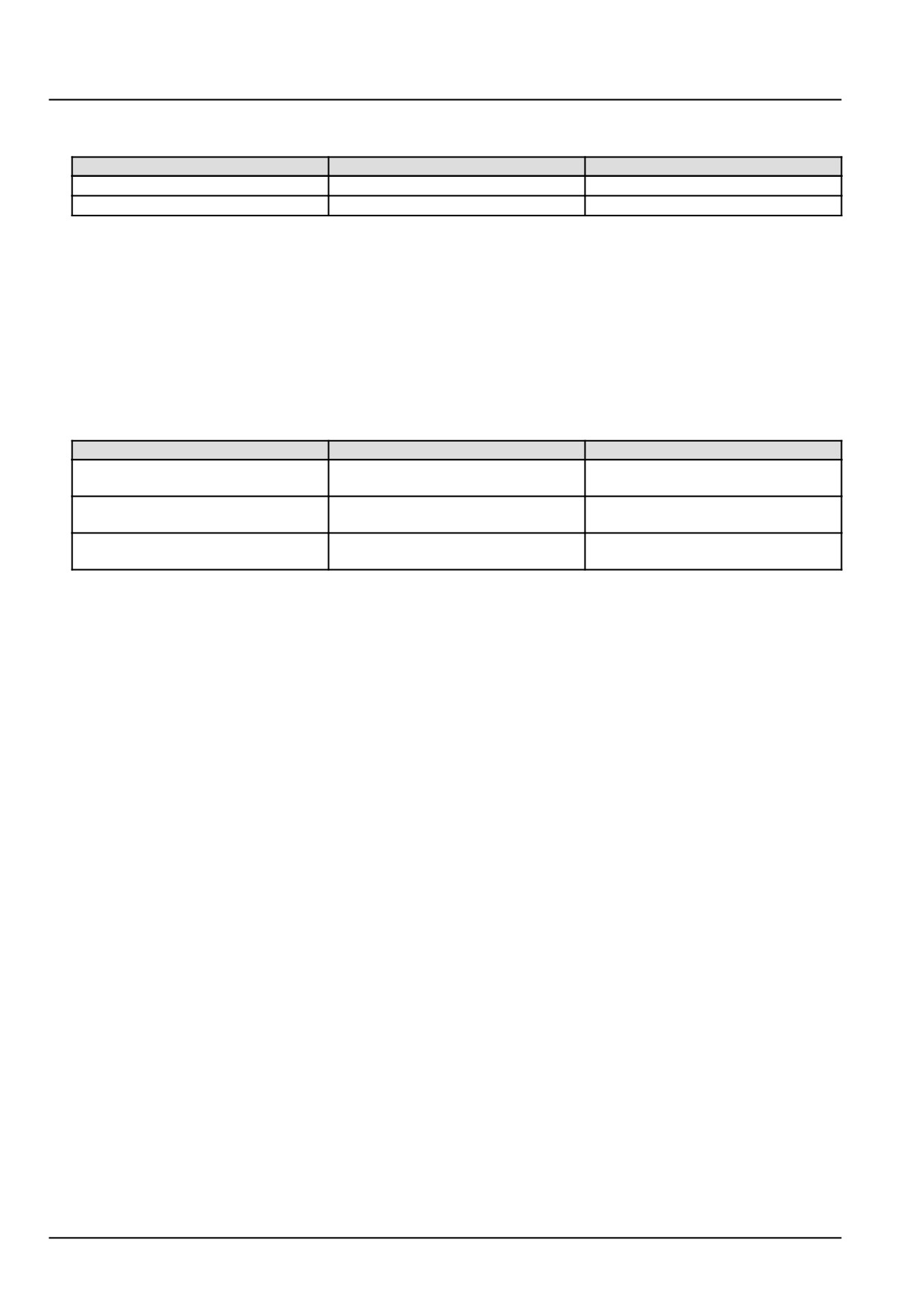
Electrical systems - FAULT CODES
With the key in the OFF position, use a multimeter to perform the following continuity check on engine harness
(EN) side :
From
To
Value
X-9001 pin A16
All pins in connector X-9001
There should be no continuity
X-9001 pin A32
All pins in connector X-9001
There should be no continuity
A. If there is continuity, there is a short circuit in the fuel injector number 1 Y-9001 wiring in the engine harness
(EN). Locate and repair the shorted conductor.
B. If there is no continuity, continue with Step 5.
5.
Check the ECU A-9000 voltage supply wiring.
Disconnect the vehicle harness (VE) from the ECU A-9000 at connector X-9102.
Place a jumper wire between X-9102 pin K28 and chassis ground. This will energize the main relay K-9102.
Use a multimeter to perform the following voltage checks on the engine harness (EN) side :
From
To
Value
X-9102 pin K01
X-9102 pin K02
There should be approximately
12.0 V.
X-9102 pin K03
X-9102 pin K04
There should be approximately
12.0 V.
X-9102 pin K05
X-9102 pin K06
There should be approximately
12.0 V.
A. If there is not approximately 12.0 V, there is a faulty ECU A-9000 voltage supply. Use the appropriate service
manual, if necessary, to locate and repair the failed conductor.
B. If there is approximately 12.0 V, check the ECU A-9000 for the appropriate software and re-flash, if necessary.
6.
Visually inspect the relevant harnesses and connectors for damage, bent or dislocated pins, corroded terminals,
or broken wires. Verify that the connectors are fully installed. Flex the harnesses involved to reveal intermittent
breaks or shorts in the wiring concerned. Operate the machine while you monitor the display.
A. If you find damage or the display indicates other than normal display readings, then repair the damage discov-
ered during the inspection or locate and repair the other than normal display condition and verify that the error
has been resolved.
B. If you do not find damage and the display indicates only normal readings, then erase the fault code and continue
operation.
Wiring harnesses - Electrical schematic sheet 01 - Power distribution and glow plugs (engine schematics)
(55.100.DP-C.20.E.01)
Wiring harnesses - Electrical schematic sheet 02 - Engine Control Unit (ECU) power and after treatment
system (engine schematics) (55.100.DP-C.20.E.02)
Wiring harnesses - Electrical schematic sheet 03 - Engine sensors and fuel injection (engine schematics)
(55.100.DP-C.20.E.03)
62
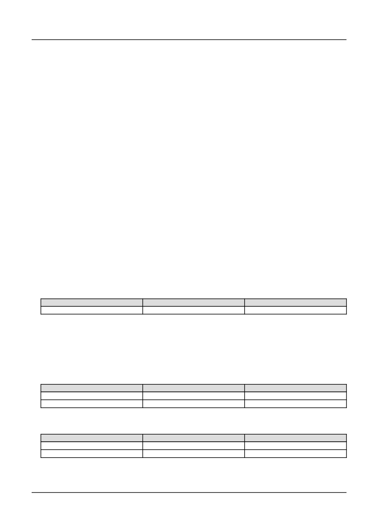
Electrical systems - FAULT CODES
DTC 162-02-Short circuit error of injector in cylinder 2
Control Module : ECU
Context:
The Engine Control Unit (ECU) A-9000 monitors the fuel injector power stages for a short circuit condition. If the ECU
A-9000 detects a short circuit condition in the injector number 2 Y-9002 circuit, this fault will occur.
Cause:
The ECU A-9000 has detected a short circuit in the fuel injector number 2 Y-9002 circuit.
Possible failure modes:
1. Faulty fuel injector number 2 Y-9002, wiring.
2. Faulty fuel injector number 2 Y-9002, internal failure.
3. Faulty ECU A-9000, software.
Solution:
1.
Verify this fault code is still present and in an active state.
Use the Easy Engine software provided on the Electronic Service Tool (EST) to check the fault status and to
perform the cylinder cut-out test.
A. If the fault is still present and active, continue with Step 2.
B. If the fault is no longer present or is in an inactive state, the fault may be intermittent and not currently active.
Continue with Step 7.
2.
Check the fuel injector number 2 Y-9002 internal resistance.
Disconnect the engine harness (EN) from the fuel injector number 2 Y-9002 at connector X-9032.
Use a multimeter to measure the resistance of fuel injector number 2 Y-9002 on the injector pins :
From
To
Value
X-9032 pin 1
X-9032 pin 2
There should be between .03 - .05 Ω
A. If there is between .03 - .05 Ω, leave connector X-9032 disconnected and continue to Step 3.
B. If the resistance is not between .03 - .05 Ω, fuel injector number 2 Y-9002 solenoid coil has failed. Replace
fuel injector number 2 Y-9002.
3.
Check the fuel injector number 2 Y-9002 engine harness (EN) wiring for a short to a voltage source.
With the key in the OFF position, use a multimeter to perform the following voltage check on the engine harness
(EN) side :
From
To
Value
X-9032 pin 1
Chassis ground
There should be no voltage.
X-9032 pin 2
Chassis ground
There should be no voltage.
With the key in the ON position, use a multimeter to perform the following voltage check on the engine harness
(EN) side :
From
To
Value
X-9032 pin 1
Chassis ground
There should be no voltage.
X-9032 pin 2
Chassis ground
There should be no voltage.
A. If there is no voltage, leave connector X-9032 disconnected and continue to Step 4.
63
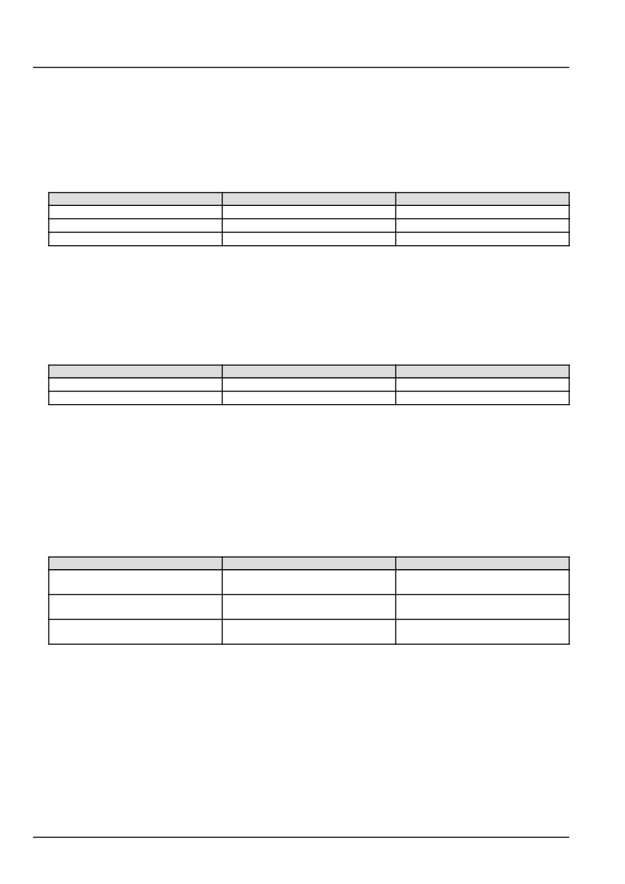
Electrical systems - FAULT CODES
B. If there is voltage, there is a short to battery or switched battery in the fuel injector number 2 Y-9002 wiring in
the engine harness (EN). Use the appropriate service manual, if necessary, to locate and repair the shorted
conductor.
4.
Check the fuel injector number 2 Y-9002 engine harness (EN) wiring for a short to ground condition.
Disconnect the engine harness (EN) from the ECU A-9000 at connector X-9001.
With the key in the OFF position, use a multimeter to perform the following continuity checks on the engine harness
(EN) side :
From
To
Value
X-9032 pin 1
X-9032 pin 2
There should be no continuity.
X-9032 pin 1
Chassis ground
There should be no continuity.
X-9032 pin 2
Chassis ground
There should be no continuity.
A. If there is no continuity, leave connector X-9001 and X-9032 disconnected. Continue to Step 5.
B. If there is continuity, there is a short circuit in the fuel injector number 2 Y-9002 wiring in the engine harness
(EN). Locate and repair the shorted conductor.
5.
Check the fuel injector number 2 Y-9002 engine harness (EN) wiring for a short circuit condition.
With the key in the OFF position, use a multimeter to perform the following continuity checks on engine harness
(EN) side :
From
To
Value
X-9001 pin A48
All pins in connector X-9001
There should be no continuity
X-9001 pin A17
All pins in connector X-9001
There should be no continuity
A. If there is continuity, there is a short circuit in the fuel injector number 2 Y-9002 wiring in the engine harness
(EN). Use the appropriate service manual, if necessary, to locate and repair the shorted conductor.
B. If there is no continuity, continue with Step 6.
6.
Check the ECU A-9000 voltage supply wiring.
Disconnect the vehicle harness (VE) from the ECU A-9000 at connector X-9102.
Place a jumper wire between X-9102 pin K28 and chassis ground. This will energize the main relay K-9102.
Use a multimeter to perform the following voltage checks on the vehicle harness (VE) side :
From
To
Value
X-9102 pin K01
X-9102 pin K02
There should be approximately
12.0 V.
X-9102 pin K03
X-9102 pin K04
There should be approximately
12.0 V.
X-9102 pin K05
X-9102 pin K06
There should be approximately
12.0 V.
A. If there is not approximately 12.0 V, there is a faulty ECU A-9000 voltage supply. Use the appropriate service
manual, if necessary, to locate and repair the failed conductor.
B. If there is approximately 12.0 V, check the ECU A-9000 for the appropriate software and re-flash, if necessary.
7.
Visually inspect the relevant harnesses and connectors for damage, bent or dislocated pins, corroded terminals,
or broken wires. Verify that the connectors are fully installed. Flex the harnesses involved to reveal intermittent
breaks or shorts in the wiring concerned. Operate the machine while you monitor the display.
A. If you find damage or the display indicates other than normal display readings, then repair the damage discov-
ered during the inspection or locate and repair the other than normal display condition and verify that the error
has been resolved.
B. If you do not find damage and the display indicates only normal readings, then erase the fault code and continue
operation.
64
Electrical systems - FAULT CODES
Wiring harnesses - Electrical schematic sheet 01 - Power distribution and glow plugs (engine schematics)
(55.100.DP-C.20.E.01)
Wiring harnesses - Electrical schematic sheet 02 - Engine Control Unit (ECU) power and after treatment
system (engine schematics) (55.100.DP-C.20.E.02)
Wiring harnesses - Electrical schematic sheet 03 - Engine sensors and fuel injection (engine schematics)
(55.100.DP-C.20.E.03)
65
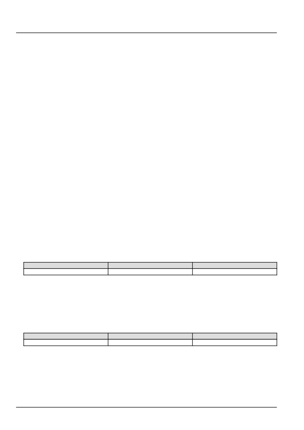
Electrical systems - FAULT CODES
DTC 162-03-Short circuit of low side to high source of injector in
cylinder 2
Control Module : ECU
Context:
The Engine Control Unit (ECU) A-9000 monitors the fuel injector power stages for a short circuit condition. If the ECU
A-9000 detects a short circuit condition in the injector number 2 Y-9002 circuit, this fault will occur.
Cause:
The ECU A-9000 has detected a short circuit between the high side driver and low side driver of the fuel injector
number 2 Y-9002.
Possible failure modes:
1. Faulty fuel injector number 2 Y-9002, wiring.
2. Faulty fuel injector number 2 Y-9002, internal failure.
3. Faulty ECU A-9000, software.
Solution:
1.
Verify this fault code is still present and in an active state.
Use the Easy Engine software provided on the Electronic Service Tool (EST) to check the fault status and to
perform the cylinder cut-out test.
A. If the fault is still present and active, continue with Step 2.
B. If the fault is no longer present or is in an inactive state, the fault may be intermittent and not currently active.
Continue with Step 6.
2.
Check the fuel injector number 2 Y-9002 internal resistance.
Disconnect the engine harness (EN) from the fuel injector number 2 Y-9002 at connector X-9032.
Use a multimeter to measure the resistance of fuel injector number 2 Y-9002 on the injector pins :
From
To
Value
X-9032 pin 1
X-9032 pin 2
There should be between .03 - .05 Ω
A. If there is between .03 - .05 Ω, leave connector X-9032 disconnected and continue to Step 3.
B. If the resistance is not between .03 - .05 Ω, fuel injector number 2 Y-9002 solenoid coil has failed. Replace
fuel injector number 2 Y-9002.
3.
Check the fuel injector number 2 Y-9002 engine harness (EN) wiring.
With the key in the OFF position, use a multimeter to perform the following continuity check on the engine harness
(EN) side :
From
To
Value
X-9032 pin 1
X-9032 pin 2
There should be no continuity.
A. If there is no continuity, leave connector X-9032 disconnected and continue to Step 4.
B. If there is continuity, there is a short circuit in the fuel injector number 2 Y-9002 wiring in the engine harness
(EN). Locate and repair the shorted conductor.
4.
Check the fuel injector number 2 Y-9001 vehicle harness (VE) wiring for a short circuit condition.
Disconnect the engine harness (EN) from the ECU A-9000 at connector X-9001.
66
Electrical systems - FAULT CODES
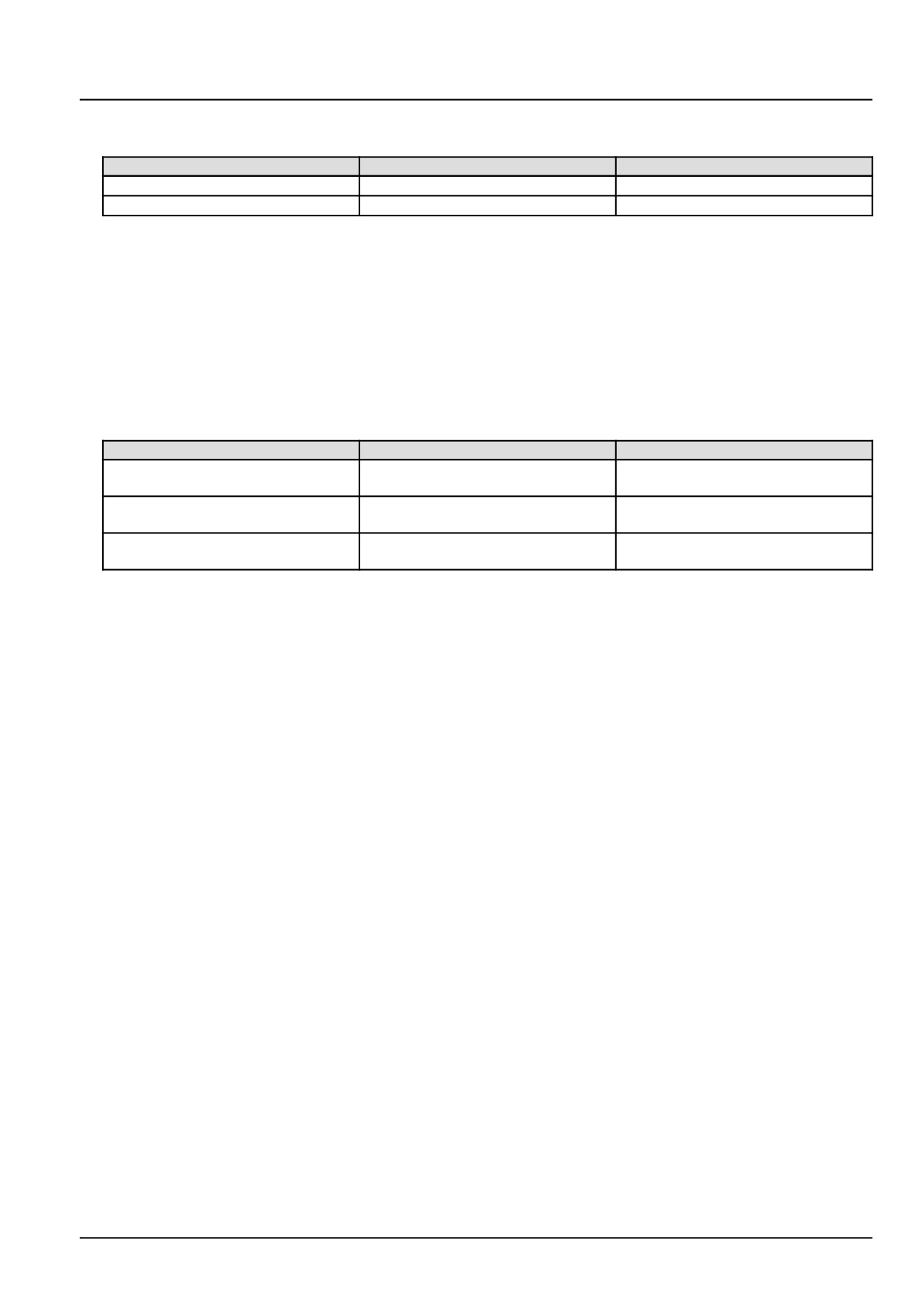
With the key in the OFF position, use a multimeter to perform the following continuity check on engine harness
(EN) side :
From
To
Value
X-9001 pin A17
All pins in connector X-9001
There should be no continuity
X-9001 pin A48
All pins in connector X-9001
There should be no continuity
A. If there is continuity, there is a short circuit in the fuel injector number 2 Y-9002 wiring in the engine harness
(EN). Locate and repair the shorted conductor.
B. If there is no continuity, continue with Step 5.
5.
Check the ECU A-9000 voltage supply wiring.
Disconnect the vehicle harness (VE) from the ECU A-9000 at connector X-9102.
Place a jumper wire between X-9102 pin K28 and chassis ground. This will energize the main relay K-9102.
Use a multimeter to perform the following voltage checks on the engine harness (EN) side :
From
To
Value
X-9102 pin K01
X-9102 pin K02
There should be approximately
12.0 V.
X-9102 pin K03
X-9102 pin K04
There should be approximately
12.0 V.
X-9102 pin K05
X-9102 pin K06
There should be approximately
12.0 V.
A. If there is not approximately 12.0 V, there is a faulty ECU A-9000 voltage supply. Use the appropriate service
manual, if necessary, to locate and repair the failed conductor.
B. If there is approximately 12.0 V, check the ECU A-9000 for the appropriate software and re-flash, if necessary.
6.
Visually inspect the relevant harnesses and connectors for damage, bent or dislocated pins, corroded terminals,
or broken wires. Verify that the connectors are fully installed. Flex the harnesses involved to reveal intermittent
breaks or shorts in the wiring concerned. Operate the machine while you monitor the display.
A. If you find damage or the display indicates other than normal display readings, then repair the damage discov-
ered during the inspection or locate and repair the other than normal display condition and verify that the error
has been resolved.
B. If you do not find damage and the display indicates only normal readings, then erase the fault code and continue
operation.
67
Electrical systems - FAULT CODES
DTC 163-02-Short circuit error of injector in cylinder 3
Control Module : ECU
Context:
The Engine Control Unit (ECU) A-9000 monitors the fuel injector power stages for a short circuit condition. If the ECU
A-9000 detects a short circuit condition in the injector number 3 Y-9003 circuit, this fault will occur.
Cause:
The ECU A-9000 has detected a short circuit in the fuel injector number 3 Y-9003 circuit.
Possible failure modes:
1. Faulty fuel injector number 3 Y-9003, wiring.
2. Faulty fuel injector number 3 Y-9003, internal failure.
3. Faulty ECU A-9000, software.
Solution:
1.
Verify this fault code is still present and in an active state.
Use the Easy Engine software provided on the Electronic Service Tool (EST) to check the fault status and to
perform the cylinder cut-out test.
A. If the fault is still present and active, continue with Step 2.
B. If the fault is no longer present or is in an inactive state, the fault may be intermittent and not currently active.
Continue with Step 7.
2.
Check the fuel injector number 3 Y-9003 internal resistance.
Disconnect the engine harness (EN) from the fuel injector number 3 Y-9003 at connector X-9031.
Use a multimeter to measure the resistance of fuel injector number 3 Y-9003 on the injector pins :
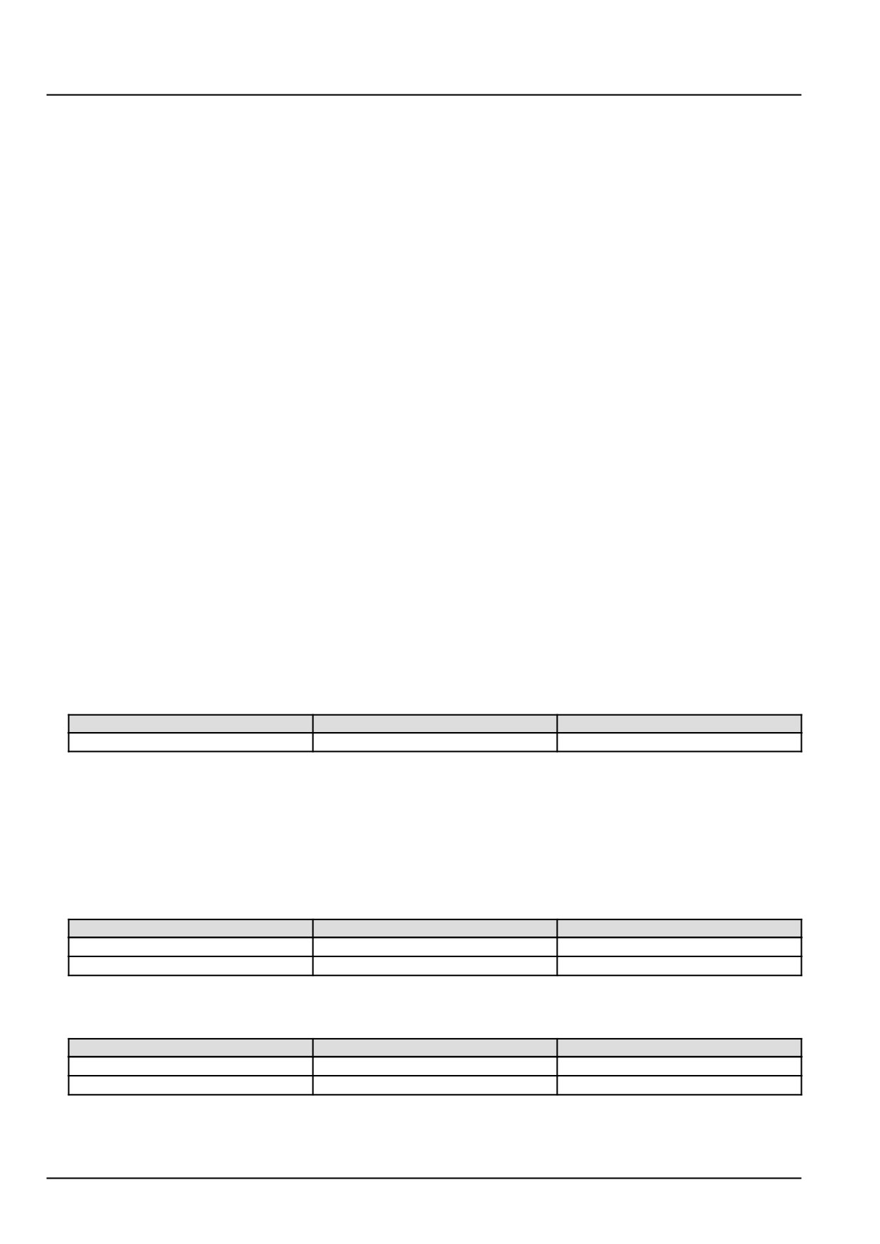
From
To
Value
X-9031 pin 1
X-9031 pin 2
There should be between .03 - .05 Ω
A. If there is between .03 - .05 Ω, leave connector X-9031 disconnected and continue to Step 3.
B. If the resistance is not between .03 - .05 Ω, fuel injector number 3 Y-9003 solenoid coil has failed. Replace
fuel injector number 3 Y-9003.
3.
Check the fuel injector number 3 Y-9003 engine harness (EN) wiring for a short to a voltage source.
With the key in the OFF position, use a multimeter to perform the following voltage check on the engine harness
(EN) side :
From
To
Value
X-9031 pin 1
Chassis ground
There should be no voltage.
X-9031 pin 2
Chassis ground
There should be no voltage.
With the key in the ON position, use a multimeter to perform the following voltage check on the engine harness
(EN) side :
From
To
Value
X-9031 pin 1
Chassis ground
There should be no voltage.
X-9031 pin 2
Chassis ground
There should be no voltage.
A. If there is no voltage, leave connector X-9031 disconnected and continue to Step 4.
68
Electrical systems - FAULT CODES
B. If there is voltage, there is a short to battery or switched battery in the fuel injector number 3 Y-9003 wiring in
the engine harness (EN). Use the appropriate service manual, if necessary, to locate and repair the shorted
conductor.
4.
Check the fuel injector number 3 Y-9003 engine harness (EN) wiring for a short to ground condition.
Disconnect the engine harness (EN) from the ECU A-9000 at connector X-9001.
With the key in the OFF position, use a multimeter to perform the following continuity checks on the engine harness
(EN) side :
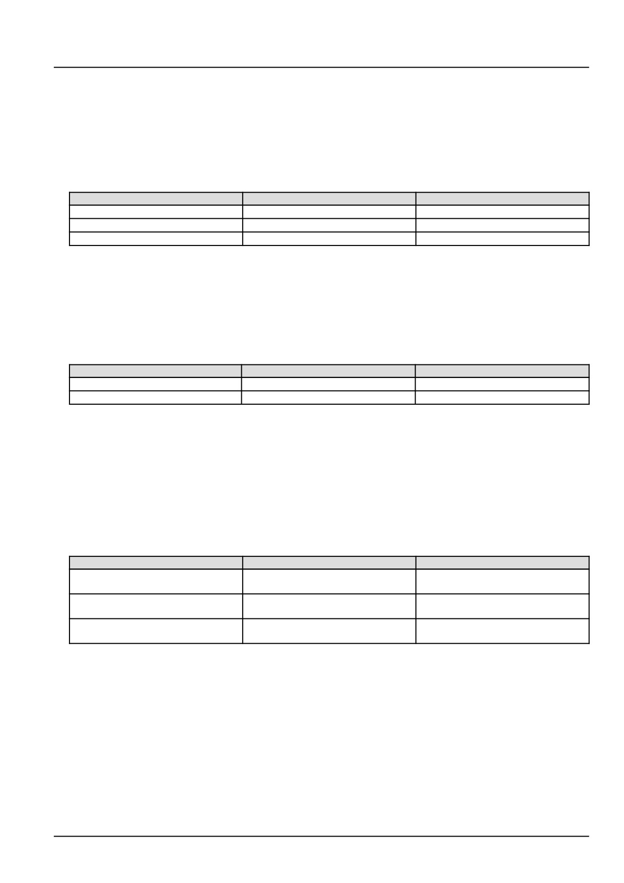
From
To
Value
X-9031 pin 1
X-9031 pin 2
There should be no continuity.
X-9031 pin 1
Chassis ground
There should be no continuity.
X-9031 pin 2
Chassis ground
There should be no continuity.
A. If there is no continuity, continue to Step 5.
B. If there is continuity, there is a short circuit in the fuel injector number 3 Y-9003 wiring in the engine harness
(EN). Locate and repair the shorted conductor.
5.
Check the fuel injector number 2 Y-9002 engine harness (EN) wiring for a short circuit condition.
With the key in the OFF position, use a multimeter to perform the following continuity checks on engine harness
(EN) side :
From
To
Value
X-9001 pin A31
All pins in connector X-9001
There should be no continuity
X-9001 pin A01
All pins in connector X-9001
There should be no continuity
A. If there is continuity, there is a short circuit in the fuel injector number 2 Y-9002 wiring in the engine harness
(EN). Use the appropriate service manual, if necessary, to locate and repair the shorted conductor.
B. If there is no continuity, continue with Step 6.
6.
Check the ECU A-9000 voltage supply wiring.
Disconnect the vehicle harness (VE) from the ECU A-9000 at connector X-9102.
Place a jumper wire between X-9102 pin K28 and chassis ground. This will energize the main relay K-9102.
Use a multimeter to perform the following voltage checks on the vehicle harness (VE) side :
From
To
Value
X-9102 pin K01
X-9102 pin K02
There should be approximately
12.0 V.
X-9102 pin K03
X-9102 pin K04
There should be approximately
12.0 V.
X-9102 pin K05
X-9102 pin K06
There should be approximately
12.0 V.
A. If there is not approximately 12.0 V, there is a faulty ECU A-9000 voltage supply. Use the appropriate service
manual, if necessary, to locate and repair the failed conductor.
B. If there is approximately 12.0 V, check the ECU A-9000 for the appropriate software and re-flash, if necessary.
7.
Visually inspect the relevant harnesses and connectors for damage, bent or dislocated pins, corroded terminals,
or broken wires. Verify that the connectors are fully installed. Flex the harnesses involved to reveal intermittent
breaks or shorts in the wiring concerned. Operate the machine while you monitor the display.
A. If you find damage or the display indicates other than normal display readings, then repair the damage discov-
ered during the inspection or locate and repair the other than normal display condition and verify that the error
has been resolved.
B. If you do not find damage and the display indicates only normal readings, then erase the fault code and continue
operation.
69
Electrical systems - FAULT CODES
Wiring harnesses - Electrical schematic sheet 01 - Power distribution and glow plugs (engine schematics)
(55.100.DP-C.20.E.01)
Wiring harnesses - Electrical schematic sheet 02 - Engine Control Unit (ECU) power and after treatment
system (engine schematics) (55.100.DP-C.20.E.02)
Wiring harnesses - Electrical schematic sheet 03 - Engine sensors and fuel injection (engine schematics)
(55.100.DP-C.20.E.03)
70
Electrical systems - FAULT CODES
DTC 163-03-Short circuit of low side to high source of injector in
cylinder 3
Control Module : ECU
Context:
The Engine Control Unit (ECU) A-9000 monitors the fuel injector power stages for a short circuit condition. If the ECU
A-9000 detects a short circuit condition in the injector number 3 Y-9003 circuit, this fault will occur.
Cause:
The ECU A-9000 has detected a short circuit between the high side driver and low side driver of the fuel injector
number 3 Y-9003.
Possible failure modes:
1. Faulty fuel injector number 3 Y-9003, wiring.
2. Faulty fuel injector number 3 Y-9003, internal failure.
3. Faulty ECU A-9000, software.
Solution:
1.
Verify this fault code is still present and in an active state.
Use the Easy Engine software provided on the Electronic Service Tool (EST) to check the fault status and to
perform the cylinder cut-out test.
A. If the fault is still present and active, continue with Step 2.
B. If the fault is no longer present or is in an inactive state, the fault may be intermittent and not currently active.
Continue with Step 7.
2.
Check the fuel injector number 3 Y-9003 internal resistance.
Disconnect the injector harness (INJ) from the fuel injector number 3 Y-9003 at connector X-9031.
Use a multimeter to measure the resistance of fuel injector number 3 Y-9003 on the injector pins :
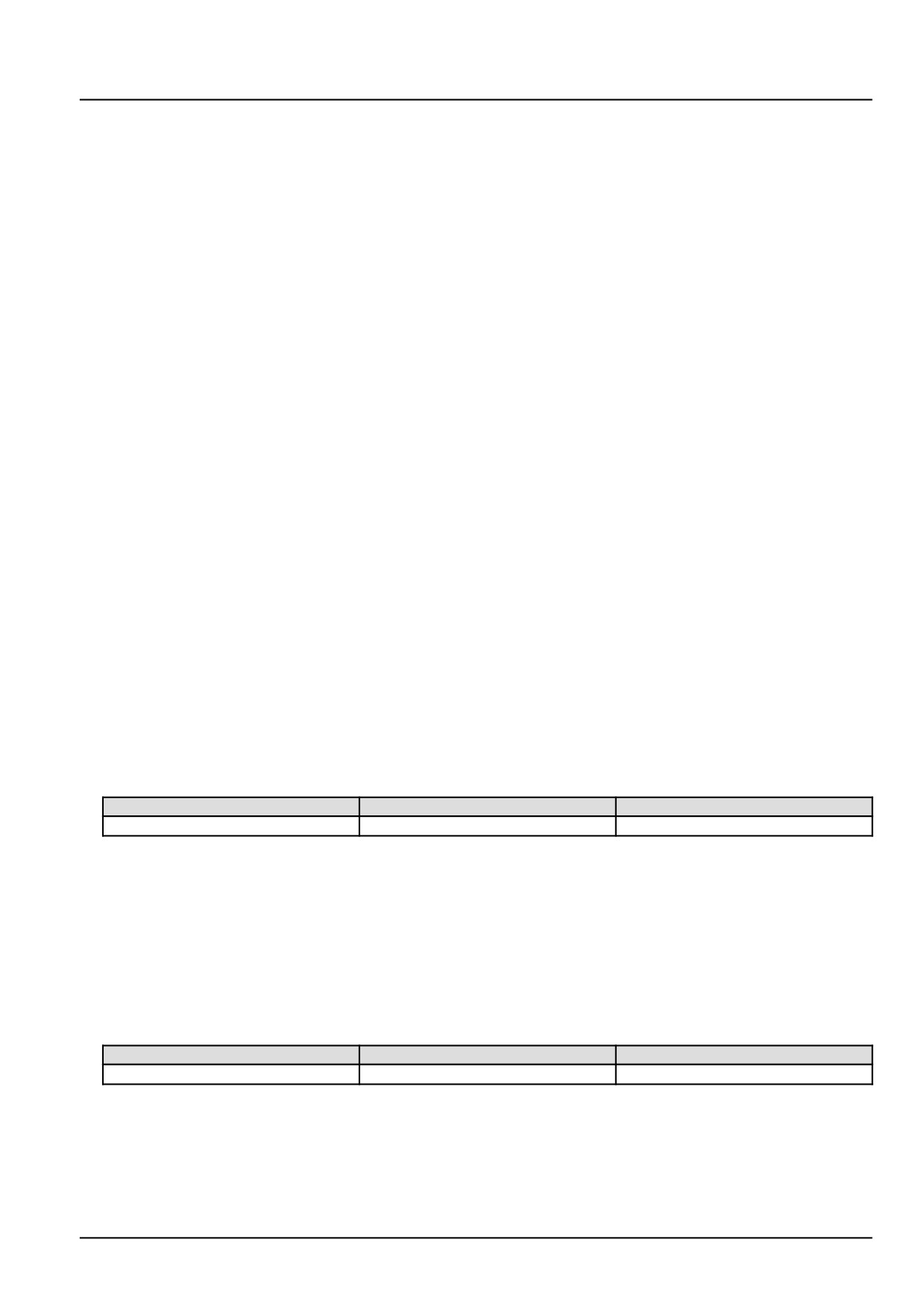
From
To
Value
X-9031 pin 1
X-9031 pin 2
There should be between .03 - .05 Ω
A. If there is between .03 - .05 Ω, leave connector X-9031 disconnected and continue to Step 3.
B. If the resistance is not between .03 - .05 Ω, fuel injector number 3 Y-9003 solenoid coil has failed. Replace
fuel injector number 3 Y-9003.
3.
Check the fuel injector number 3 Y-9003 injector harness (INJ) wiring.
Disconnect the vehicle harness (VE) from the engine interface at connector X-9139.
With the key in the OFF position, use a multimeter to perform the following continuity check on the injector harness
(INJ) side :
From
To
Value
X-9031 pin 1
X-9031 pin 2
There should be no continuity.
A. If there is no continuity, leave connectors X-9031 and X-9139 disconnected and continue to Step 4.
B. If there is continuity, there is a short circuit in the fuel injector number 3 Y-9003 wiring in the injector harness
(INJ) between wires INJ-270 and INJ-271. Locate and repair the shorted conductor.
4.
Check the fuel injector number 3 Y-9003 vehicle harness (VE) wiring for a short circuit condition.
71
Electrical systems - FAULT CODES
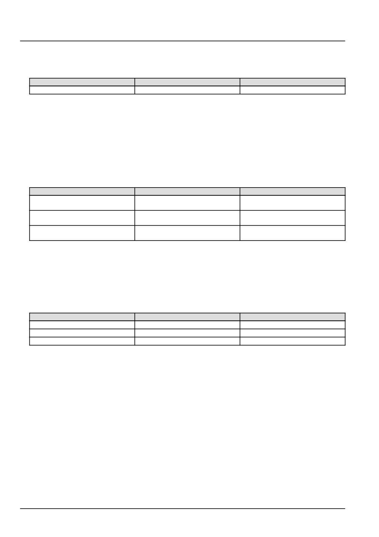
Disconnect the vehicle harness (VE) from the ECU A-9000 at connector X-9121.
With the key in the OFF position, use a multimeter to perform the following continuity check on vehicle harness
(VE) side :
From
To
Value
X-9139 pin D
X-9139 pin C
There should be no continuity
A. If there is continuity, there is a short circuit in the fuel injector number 3 Y-9003 wiring in the vehicle harness
(VE) between wires VE-9128 and VE-9127. Use the appropriate service manual, if necessary, to locate and
repair the shorted conductor.
B. If there is no continuity, continue with Step 5.
5.
Check the ECU A-9000 voltage supply wiring.
Disconnect the vehicle harness (VE) from the ECU A-9000 at connector X-9122.
With the key in the ON position, use a multimeter to perform the following voltage checks from the vehicle harness
(VE) side :
From
To
Value
X-9122 pin K03
chassis ground
There should be approximately
12.0 V
X-9122 pin K05
chassis ground
There should be approximately
12.0 V
X-9122 pin K01
chassis ground
There should be approximately
12.0 V
A. If there is approximately 12.0 V, leave connector X-9122 disconnected and continue to Step 6.
B. If there is not approximately 12.0 V, there is a faulty ECU A-9000 voltage supply. Use the appropriate service
manual, if necessary, to locate and repair the failed conductor.
6.
Check the ECU A-9000 ground supply.
With the key in the OFF position, use a multimeter to perform the following continuity check on the vehicle harness
(VE) side : :
From
To
Value
X-9122 pin K02
chassis ground
There should be continuity.
X-9122 pin K04
chassis ground
There should be continuity.
X-9122 pin K06
chassis ground
There should be continuity.
A. If there is no continuity, there is a faulty ECU A-9000 ground supply. Use the appropriate service manual, if
necessary, to locate and repair the failed conductor.
B. If there is continuity, check the ECU A-9000 for the appropriate software and re-flash, if necessary.
7.
Visually inspect the relevant harnesses and connectors for damage, bent or dislocated pins, corroded terminals,
or broken wires. Verify that the connectors are fully installed. Flex the harnesses involved to reveal intermittent
breaks or shorts in the wiring concerned. Operate the machine while you monitor the display.
A. If you find damage or the display indicates other than normal display readings, then repair the damage discov-
ered during the inspection or locate and repair the other than normal display condition and verify that the error
has been resolved.
B. If you do not find damage and the display indicates only normal readings, then erase the fault code and continue
operation.
Wiring harnesses - Electrical schematic sheet 04 - Engine Control Unit (ECU) vehicle connector
(55.100.DP-C.20.E.04)
Wiring harnesses - Electrical schematic sheet 05 - Engine Control Unit (ECU) engine connector
(55.100.DP-C.20.E.05)
Wiring harnesses - Electrical schematic sheet 06 - Engine control and fuel injection (55.100.DP-C.20.E.06)
72
Electrical systems - FAULT CODES
DTC 167-02-Open load error of injector in cylinder 1
Control Module : ECU
NOTE: If a fuel injector is replaced, it is necessary to program the new injector IMA code using the Electronic Service
Tool (EST). The IMA code may be under the paint on the fuel injector. For more information regarding programming
IMA codes, see Fuel injectors - Configure - IMA codes (10.218).
Context:
The Engine Control Unit (ECU) A-9000 monitors the fuel injector number 1 Y-9001 circuit. If the ECU A-9000 deter-
mines that there is an open circuit condition in the fuel injector number 1 Y-9001 circuit, this fault will occur.
Cause:
The ECU A-9000 has detected an open circuit in the fuel injector number 1 Y-9001 circuit.
Possible failure modes:
1. Faulty fuel injector number 1 Y-9001 wiring, open circuit.
2. Faulty fuel injector number 1 Y-9001, internal failure.
3. Faulty ECU A-9000, software.
Solution:
1.
Verify fault is present and active.
Use the Electronic Service Tool (EST) to check the status of this fault.
A. If the fault is present and active, continue with Step 2.
B. If the fault is no longer present or in an inactive state, the fault may be intermittent and not currently active.
Continue with Step 4.
2.
Check fuel injector number 1 for an internal failure.
Disconnect the engine harness (EN) from fuel injector number 1 Y-9001 at connector X-9030.
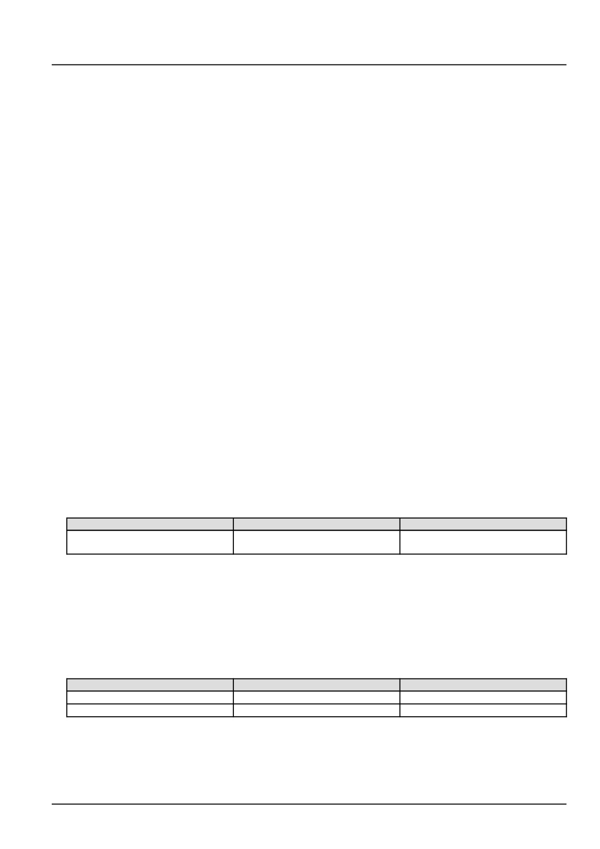
Use a multimeter to perform the following resistance check on the fuel injector pins :
From
To
Value
X-9030 pin 1
X-9030 pin 2
There should be approximately 0.3
- 0.5 Ω.
A. If the specified range is not measured, the fuel injector has failed. Replace the fuel injector number 1 Y-9001.
B. If the specified range is measured, leave connector X-9030 disconnected and continue to Step 3.
3.
Check the fuel injector number 1 Y-9001 engine harness (EN) wiring for an open circuit.
Disconnect the engine harness (EN) from the ECU A-9000 at connector X-9001.
With they key in the OFF position, use a multimeter to perform the following continuity check on the engine harness
(EN) side:
From
To
Value
X-9030 pin 1
X-9001 pin A16
There should be continuity.
X-9030 pin 2
X-9001 pin A32
There should be continuity.
A. If there is no continuity, there is an open circuit in the fuel injector number 1 Y-9001 engine harness (EN) wiring.
Locate and repair the broken conductor.
B. If there is continuity, check the ECU A-9000 for the appropriate software and re-flash, if necessary.
73
Electrical systems - FAULT CODES
4. Visually inspect the relevant harnesses and connectors for damage, bent or dislocated pins, corroded terminals,
or broken wires. Verify that the connectors are fully installed. Flex the harnesses involved to reveal intermittent
breaks or shorts in the wiring concerned. Operate the machine while you monitor the display.
A. If you find damage or the display indicates other than normal display readings, then repair the damage discov-
ered during the inspection or locate and repair the other than normal display condition and verify that the error
has been resolved.
B. If you do not find damage and the display indicates only normal readings, then erase the fault code and continue
operation.
Wiring harnesses - Electrical schematic sheet 03 - Engine sensors and fuel injection (engine schematics)
(55.100.DP-C.20.E.03)
74
Electrical systems - FAULT CODES
DTC 168-02-Open load error of injector in cylinder 2
Control Module : ECU
NOTE: If a fuel injector is replaced, it is necessary to program the new injector IMA code using the Electronic Service
Tool (EST). The IMA code may be under the paint on the fuel injector. For more information regarding programming
IMA codes, see Fuel injectors - Configure - IMA codes (10.218).
Context:
The Engine Control Unit (ECU) A-9000 monitors the fuel injector number 2 Y-9002 circuit. If the ECU A-9000 deter-
mines that there is an open circuit condition in the fuel injector number 2 Y-9002 circuit, this fault will occur.
Cause:
The ECU A-9000 has detected an open circuit in the fuel injector number 2 Y-9002 circuit.
Possible failure modes:
1. Faulty fuel injector number 2 Y-9002 wiring, open circuit.
2. Faulty fuel injector number 2 Y-9002, internal failure.
3. Faulty ECU A-9000, software.
Solution:
1.
Verify fault is present and active.
Use the Electronic Service Tool (EST) to check the status of this fault.
A. If the fault is present and active, continue with Step 2.
B. If the fault is no longer present or in an inactive state, the fault may be intermittent and not currently active.
Continue with Step 4.
2.
Check fuel injector number 2 for an internal failure.
Disconnect the engine harness (EN) from fuel injector number 2 Y-9002 at connector X-9032.
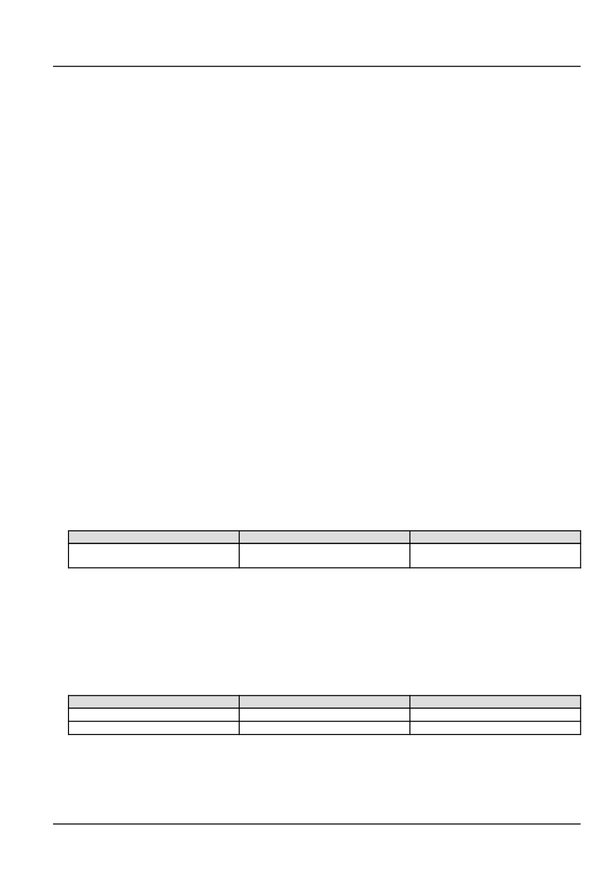
Use a multimeter to perform the following resistance check on the fuel injector pins :
From
To
Value
X-9032 pin 1
X-9032 pin 2
There should be approximately 0.3
- 0.5 Ω.
A. If the specified range is not measured, the fuel injector has failed. Replace the fuel injector number 2 Y-9002.
B. If the specified range is measured, leave connector X-9032 disconnected and continue to Step 3.
3.
Check the fuel injector number 2 Y-9002 engine harness (EN) wiring for an open circuit.
Disconnect the engine harness (EN) from the ECU A-9000 at connector X-9001.
With they key in the OFF position, use a multimeter to perform the following continuity check on the engine harness
(EN) side:
From
To
Value
X-9032 pin 1
X-9001 pin A17
There should be continuity.
X-9032 pin 2
X-9001 pin A48
There should be continuity.
A. If there is no continuity, there is an open circuit in the fuel injector number 2 Y-9002 engine harness (EN) wiring.
Locate and repair the broken conductor.
B. If there is continuity, check the ECU A-9000 for the appropriate software and re-flash, if necessary.
75
Electrical systems - FAULT CODES
4. Visually inspect the relevant harnesses and connectors for damage, bent or dislocated pins, corroded terminals,
or broken wires. Verify that the connectors are fully installed. Flex the harnesses involved to reveal intermittent
breaks or shorts in the wiring concerned. Operate the machine while you monitor the display.
A. If you find damage or the display indicates other than normal display readings, then repair the damage discov-
ered during the inspection or locate and repair the other than normal display condition and verify that the error
has been resolved.
B. If you do not find damage and the display indicates only normal readings, then erase the fault code and continue
operation.
Wiring harnesses - Electrical schematic sheet 03 - Engine sensors and fuel injection (engine schematics)
(55.100.DP-C.20.E.03)
76
Electrical systems - FAULT CODES
DTC 169-02-Open load error of injector in cylinder 3
Control Module : ECU
NOTE: If a fuel injector is replaced, it is necessary to program the new injector IMA code using the Electronic Service
Tool (EST). The IMA code may be under the paint on the fuel injector. For more information regarding programming
IMA codes, see Fuel injectors - Configure - IMA codes (10.218).
Context:
The Engine Control Unit (ECU) A-9000 monitors the fuel injector number 3 Y-9003 circuit. If the ECU A-9000 deter-
mines that there is an open circuit condition in the fuel injector number 3 Y-9003 circuit, this fault will occur.
Cause:
The ECU A-9000 has detected an open circuit in the fuel injector number 3 Y-9003 circuit.
Possible failure modes:
1. Faulty fuel injector number 3 Y-9003 wiring, open circuit.
2. Faulty fuel injector number 3 Y-9003, internal failure.
3. Faulty ECU A-9000, software.
Solution:
1.
Verify fault is present and active.
Use the Electronic Service Tool (EST) to check the status of this fault.
A. If the fault is present and active, continue with Step 2.
B. If the fault is no longer present or in an inactive state, the fault may be intermittent and not currently active.
Continue with Step 4.
2.
Check fuel injector number 3 for an internal failure.
Disconnect the engine harness (EN) from fuel injector number 3 Y-9003 at connector X-9031.
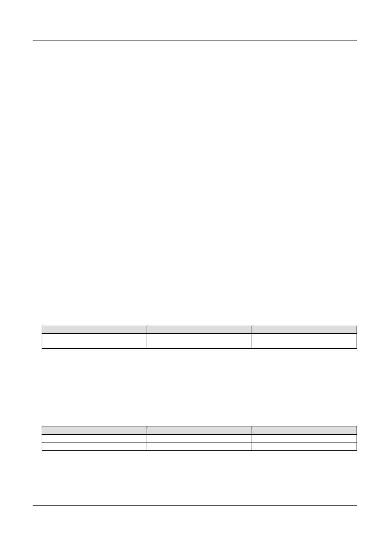
Use a multimeter to perform the following resistance check on the fuel injector pins :
From
To
Value
X-9031 pin 1
X-9031 pin 2
There should be approximately 0.3
- 0.5 Ω.
A. If the specified range is not measured, the fuel injector has failed. Replace the fuel injector number 3 Y-9003.
B. If the specified range is measured, leave connector X-9031 disconnected and continue to Step 3.
3.
Check the fuel injector number 3 Y-9003 engine harness (EN) wiring for an open circuit.
Disconnect the engine harness (EN) from the ECU A-9000 at connector X-9001.
With they key in the OFF position, use a multimeter to perform the following continuity check on the engine harness
(EN) side:
From
To
Value
X-9031 pin 1
X-9001 pin A31
There should be continuity.
X-9031 pin 2
X-9001 pin A01
There should be continuity.
A. If there is no continuity, there is an open circuit in the fuel injector number 3 Y-9003 engine harness (EN) wiring.
Locate and repair the broken conductor.
B. If there is continuity, check the ECU A-9000 for the appropriate software and re-flash, if necessary.
77
Electrical systems - FAULT CODES
4. Visually inspect the relevant harnesses and connectors for damage, bent or dislocated pins, corroded terminals,
or broken wires. Verify that the connectors are fully installed. Flex the harnesses involved to reveal intermittent
breaks or shorts in the wiring concerned. Operate the machine while you monitor the display.
A. If you find damage or the display indicates other than normal display readings, then repair the damage discov-
ered during the inspection or locate and repair the other than normal display condition and verify that the error
has been resolved.
B. If you do not find damage and the display indicates only normal readings, then erase the fault code and continue
operation.
Wiring harnesses - Electrical schematic sheet 03 - Engine sensors and fuel injection (engine schematics)
(55.100.DP-C.20.E.03)
78
Electrical systems - FAULT CODES
DTC 171-03-Injection bank 1 short circuit failure (all injectors of
the same bank can be affected)
Control Module : ECU
Context:
The Engine Control Unit (ECU) A-9000 monitors the fuel injector harness for a short circuit condition. If the ECU
A-9000 detects a short circuit pattern in the bank 1 fuel injectors, this fault will occur. Fuel injector number 1 Y-9001
is the only fuel injector for bank 1.
Cause:
The ECU A-9000 has detected a a short circuit pattern in the bank 1 fuel injector harness.
Possible failure modes:
1. Faulty fuel injector bank 1 wiring, short circuit.
2. Fault ECU A-9000, software.
Solution:
1.
Verify fault is present and active.
Use the Electronic Service Tool (EST) to check the status of this fault.
A. If the fault is present and active, continue with Step 2.
B. If the fault is no longer present or in an inactive state, the fault may be intermittent and not currently active.
Continue with Step 4.
2.
Use the Electronic Service Tool (EST) to check for other active faults that may have caused this fault to occur.
A. If any of the related faults are active, diagnose them first and then return to this fault.
B. If none of the related faults are active, continue to Step 3.
3.
Check the fuel injector 1 Y-9001 harness for a short circuit condition.
Disconnect the engine harness (EN) from fuel injector number 1 Y-9001 at connector X-9030.
With the key in the OFF position, use a multimeter to perform the following continuity check on the engine harness
(EN) side :
From
To
Value
X-9030 pin 1
X-9030 pin 2
There should be no continuity.
A. If there is continuity, there is a short circuit in the fuel injector bank 1 harness. Locate and repair the shorted
conductor.
B. If there is no continuity, check the ECU A-9000 for the appropriate software and re-flash, if necessary.
4.
Visually inspect the relevant harnesses and connectors for damage, bent or dislocated pins, corroded terminals,
or broken wires. Verify that the connectors are fully installed. Flex the harnesses involved to reveal intermittent
breaks or shorts in the wiring concerned. Operate the machine while you monitor the display.
A. If you find damage or the display indicates other than normal display readings, then repair the damage discov-
ered during the inspection or locate and repair the other than normal display condition and verify that the error
has been resolved.
B. If you do not find damage and the display indicates only normal readings, then erase the fault code and continue
operation.
Wiring harnesses - Electrical schematic sheet 03 - Engine sensors and fuel injection (engine schematics)
(55.100.DP-C.20.E.03)
79
Electrical systems - FAULT CODES
DTC 173-03-Injection bank 2 short circuit failure (all injectors of
the same bank can be affected)
Control Module : ECU
Context:
The Engine Control Unit (ECU) A-9000 monitors the fuel injector harness for a short circuit condition. If the ECU
A-9000 detects a short circuit pattern in the fuel injector harness of both bank 2 fuel injections, this fault will occur.
The bank 2 fuel injectors are fuel injector number 2 Y-9002 and fuel injector number 3 Y-9003.
Cause:
The ECU A-9000 has detected a a short circuit pattern between both bank 2 fuel injectors.
Possible failure modes:
1. Faulty bank 2 fuel injector wiring, short circuit.
2. Fault ECU A-9000, software.
Solution:
1.
Verify fault is present and active.
Use the Electronic Service Tool (EST) to check the status of this fault.
A. If the fault is present and active, continue with Step 2.
B. If the fault is no longer present or in an inactive state, the fault may be intermittent and not currently active.
Continue with Step 4.
2.
Use the Electronic Service Tool (EST) to check for other active faults that may have caused this fault to occur.
A. If any of the related faults are active, diagnose them first and then return to this fault.
B. If none of the related faults are active, continue to Step 3.
3.
Check the fuel injector 2 and 3 harnesses for a short circuit condition.
Disconnect the engine harness (EN) from fuel injector number 2 Y-9002 at connector X-9032.
Disconnect the engine harness (EN) from fuel injector number 3 Y-9003 at connector X-9031.
With the key in the OFF position, use a multimeter to perform the following continuity check on the engine harness
(EN) side :
From
To
Value
X-9032 pin 1
X-9031 pin 2
There should be no continuity.
X-9032 pin 2
X-9031 pin 1
There should be no continuity.
X-9032 pin 1
X-9031 pin 1
There should be no continuity.
X-9032 pin 2
X-9031 pin 2
There should be no continuity.
X-9032 pin 1
X-9032 pin 2
There should be no continuity.
X-9031 pin 1
X-9031 pin 2
There should be no continuity.
A. If there is continuity, there is a short circuit in the fuel injector bank 2 harness. Locate and repair the shorted
conductor.
B. If there is no continuity, check the ECU A-9000 for the appropriate software and re-flash, if necessary.
4.
Visually inspect the relevant harnesses and connectors for damage, bent or dislocated pins, corroded terminals,
or broken wires. Verify that the connectors are fully installed. Flex the harnesses involved to reveal intermittent
breaks or shorts in the wiring concerned. Operate the machine while you monitor the display.
80
Electrical systems - FAULT CODES
A. If you find damage or the display indicates other than normal display readings, then repair the damage discov-
ered during the inspection or locate and repair the other than normal display condition and verify that the error
has been resolved.
B. If you do not find damage and the display indicates only normal readings, then erase the fault code and continue
operation.
Wiring harnesses - Electrical schematic sheet 03 - Engine sensors and fuel injection (engine schematics)
(55.100.DP-C.20.E.03)
81
Electrical systems - FAULT CODES
DTC 17C-12-ECU internal failure - Injector CY33x component
Control Module : ECU
Context:
The Engine Control Unit (ECU) A-9000 monitors diagnostic checks on the fuel injection power stages. This diagnostic
procedure uses pattern detection to identify specific errors and can trigger the appropriate reaction. If the ECU A-9000
detects a specific combination of errors in the injection power stages, this fault will occur.
Solution:
1. Check the ECU A-9000 for the appropriate software and re-flash, if necessary.
A. If the fault has been resolved, return the machine to service.
B. If the fault has not been resolved, escalate an ASIST concern.
82
Electrical systems - FAULT CODES
DTC 17E-02-Number of desired injections exceeds threshold
Control Module : ECU
Context:
The Engine Control Unit (ECU) A-9000 monitors the requested number of fuel injections. If the ECU A-9000 deter-
mines that the number of requested injections is greater than the current capability of the fuel injection system, this
fault will occur,
Cause:
The ECU A-9000 has determined that the number of requested fuel injections has exceeded the current capability of
the fuel injection system.
Possible failure modes:
1. Faulty battery, low voltage.
2. Faulty ECU A-9000 power supply.
3. Faulty ECU A-9000, software.
Solution:
1.
Check battery voltage.
Load test the battery. There should be approximately 12.0 V.
A. If the battery passes the load test, continue to Step 2.
B. If the battery fails the load test, the battery has failed. Replace the battery.
2.
Check the ECU A-9000 voltage supply wiring.
Disconnect the vehicle harness (VE) from the ECU A-9000 at connector X-9102.
Place a jumper wire between X-9102 pin K28 and chassis ground. This will energize the main relay K-9102.
Use a multimeter to perform the following voltage checks on the engine harness (EN) side :
From
To
Value
X-9102 pin K01
X-9102 pin K02
There should be approximately
12.0 V.
X-9102 pin K03
X-9102 pin K04
There should be approximately
12.0 V.
X-9102 pin K05
X-9102 pin K06
There should be approximately
12.0 V.
A. If there is not approximately 12.0 V, there is a faulty ECU A-9000 voltage supply. Use the appropriate service
manual, if necessary, to locate and repair the failed conductor.
B. If there is approximately 12.0 V, continue to Step 3.
3.
Check the ECU A-9000 for the appropriate software and re-flash, if necessary.
A. If the fault has been resolved, return the machine to service.
B. If the fault has not been resolved, escalate an ASIST concern.
Wiring harnesses - Electrical schematic sheet 01 - Power distribution and glow plugs (engine schematics)
(55.100.DP-C.20.E.01)
Wiring harnesses - Electrical schematic sheet 02 - Engine Control Unit (ECU) power and after treatment
system (engine schematics) (55.100.DP-C.20.E.02)
83
Electrical systems - FAULT CODES
DTC 17E-03-Exceeded the number of injections for a given engine
speed
Control Module : ECU
Context:
The ECU A-9000 monitors the requested number of fuel injections and the current capability of the injection system
fulfilling that request. If the ECU A-9000 determines that the requested number of injections is greater than the current
capability of the fuel injection system for the current engine speed, this fault will occur.
Cause:
The ECU A-9000 has determined that the requested number of fuel injections is greater than the capability of the fuel
injection system based on engine speed.
Solution:
1. Check the ECU A-9000 for the appropriate software and re-flash, if necessary.
A. If the fault has been resolved, return the machine to service.
B. If the fault has not been resolved, escalate an ASIST concern.
84