New Holland Tractor T4.75F, T4.85F, T4.95F, T4.105F. OPERATOR’S MANUAL (2013) - page 5
7 - MAINTENANCE
Opening the hood
To access the engine components and carry out inspec-
tion, lubrication and maintenance operations, the bonnet
must be opened (1). The following instructions describe
the procedure to be followed.
The hood is hinged at the rear to allow easy and safe
access to the various engine components.
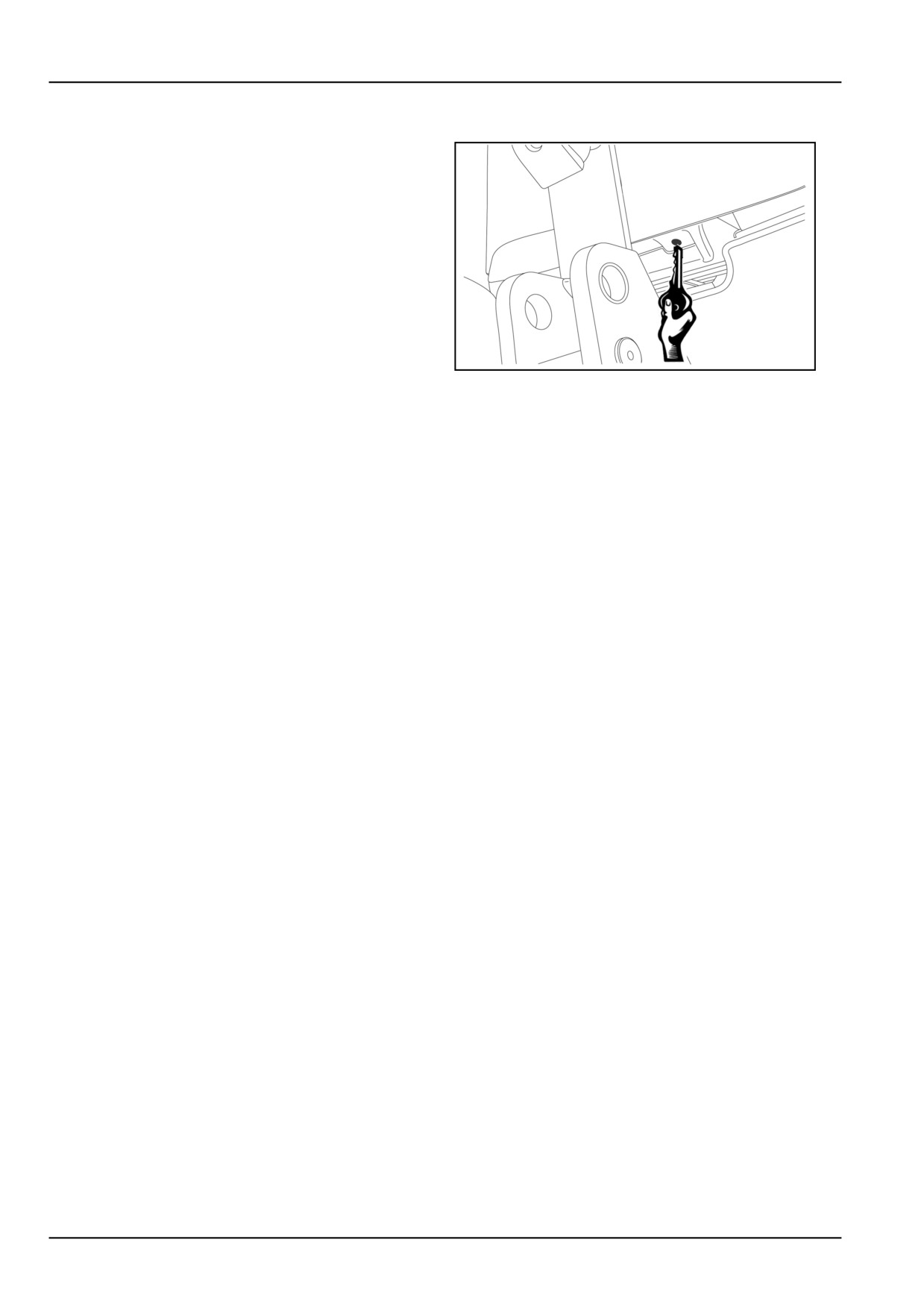
To open the bonnet, insert the engine starter key into the
hole shown (on the front of the bonnet) and press on the
catch to unhook the bonnet. Raise the bonnet with the
special handle, an internal strut will keep it in the raised
position.
DCSPFNEGB024S7A
1
To close the hood, push it fully in. An audible click will
signal engagement of the locking catch. Check that the
hood is properly closed.
7-10
7 - MAINTENANCE
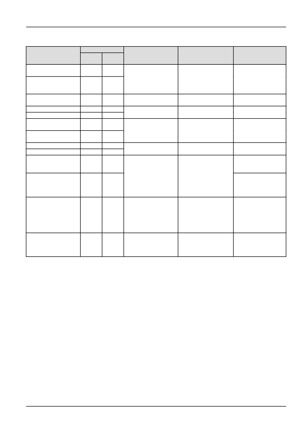
Fluids and lubricants
COMPONENT TO BE
QUANTITY
RECOMMENDED
SPECIFICATION NEW
INTERNATIONAL
FILLED OR TOPPED
NEW HOLLAND
l
US gal
HOLLAND
SPECIFICATION
UP
PRODUCTS
Cooling system,
Mixture of water
10,5
2.77
models with no cab:
and antifreeze
FLEETGUARD®
NH900A
-
Cooling system,
12,5
3.30
COMPLEAT™ at 50 % +
models with cab:
50 %
Windscreen wash
2
0.53
Water & cleaning liquid
-
-
reservoir
Fuel tank:
77
20.34
Decanted, filtered
-
-
Reduced fuel tank:
67
17.70
diesel fuel
Engine oil sump:
NH330H
8,5
2.25
NEW HOLLAND
T4.75F - T4.85F
SAE 15W40
API CH-4
AMBRA
Engine oil sump:
NH324H
ACEA E7/E5
9,5
2.51
MASTERGOLD HSP
T4.95F - T4.105F
SAE 10W30
Brakes circuit
0,5
0.13
BRAKE LHM FLUID
NH610A
ISO 7308
With front brakes
0,2
0.05
API GL-4
Front axle housing:
2,8
0.74
ISO 32/46
NEW HOLLAND
SAE 10W30
AMBRA MULTI
Front axle final drives
NH410B
G™ HYDRAULIC
API GL-5
(each) - with brakes
1,75
0.46
TRANSMISSION OIL
MIL-L-2105 D
Front axle final drives
1,0
0.26
SAE 80W90
(each) - without brakes
Rear axle (bevel
drive, final drives and
NEW HOLLAND
API GL-4
brakes), transmission,
AMBRA MULTI
44
11.62
NH410B
ISO 32/46
hydraulic lift, power
G™ HYDRAULIC
SAE 10W30
take-off and hydrostatic
TRANSMISSION OIL
steering:
Grease fittings
NEW HOLLAND
NH710A
NLGI 2
AMBRA GR-9
MULTI-PURPOSE
GREASE
7-11
7 - MAINTENANCE
Engine Oil
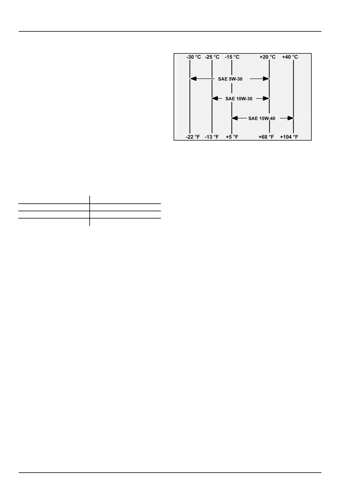
The correct degree of engine oil viscosity depends on the
environment temperature. Refer to the chart on the right
when selecting the oil grade for your tractor engine.
NOTE: In areas where prolonged periods of extreme tem-
peratures are encountered, local lubrication practices are
acceptable. The use of SAE 5W with extremely low tem-
peratures and SAE 50 for extremely high temperatures is
advised.
DCUTDNEGB126S4A
1
Sulphur in Fuel
The engine oil change frequency is given in this section.
However, locally available fuel may have a high sulphur
content, in which case the engine oil change period (as
noted in this Section) should be adjusted as follows:
Sulphur content
Oil Change Period
less than 0.5 %
normal
0.5
- 1.0 %
half the normal
more than 1.0 %
one quarter normal
NOTICE: Avoid using fuel with sulphur content higher than 1.3 %
7-12
7 - MAINTENANCE
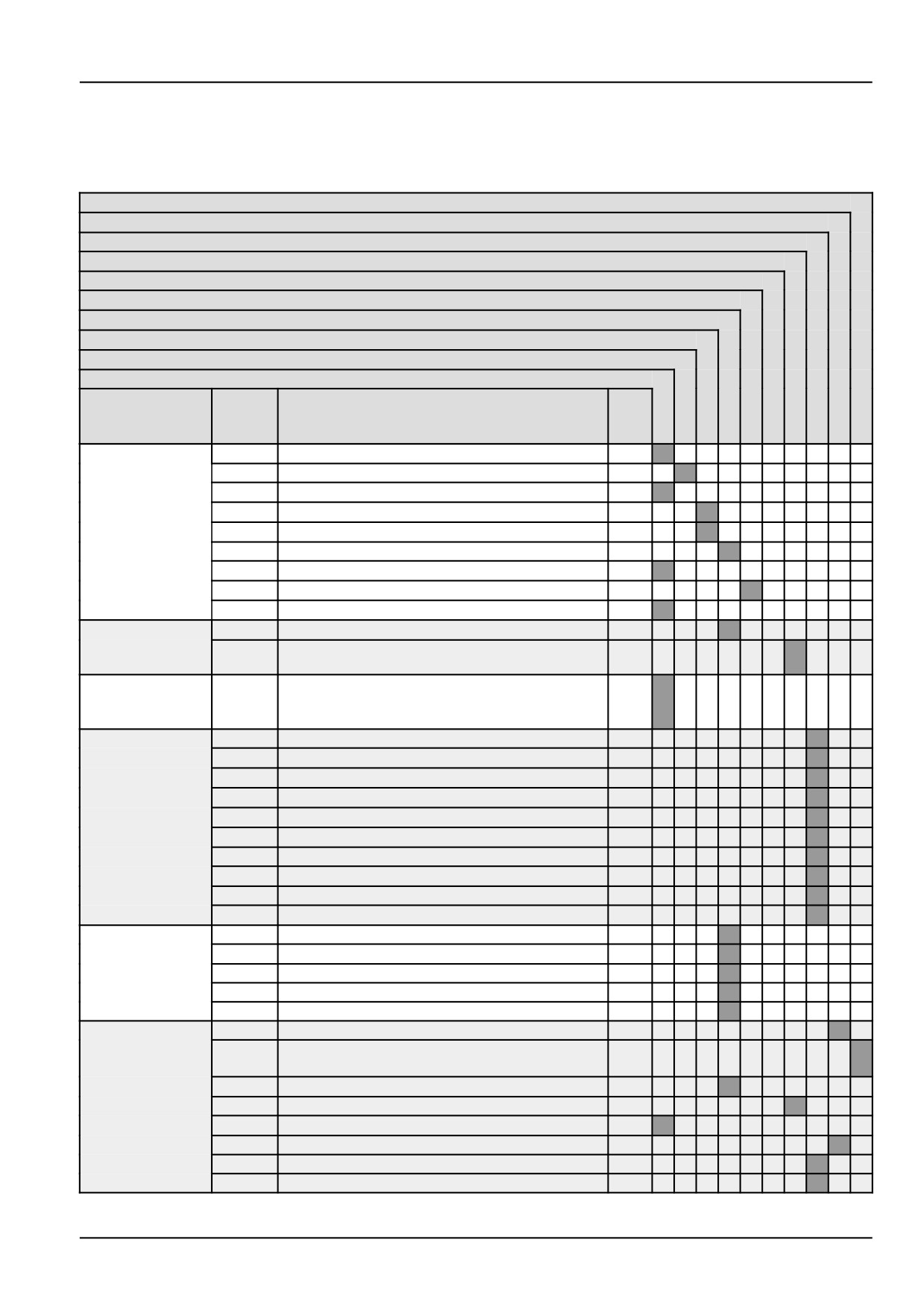
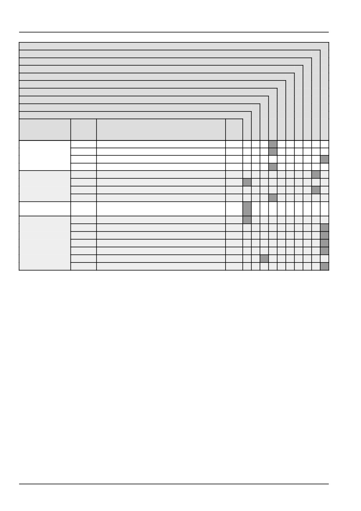
MAINTENANCE CHART
Maintenance Chart
Replace
Change fluid
Grease
Filling
Drain fluid
Tighten
Cleaning
Adjust
Level make up
Check
Interval
Page
Maintenance action
No.
no.
of
pts.
AS REQUIRED
7-15
Radiator expansion tank
X
7-15
Windscreen washer tank
X
7-15
Road light
X
7-16
Clutch pedal adjustment
X
7-16
Parking brake or parking lock
X
7-16
Radiator
X
7-17
Tyre pressure
X
7-18
Wheel nuts torque
X
7-18
Brake pedals
X
AT WARNING
7-19
Engine air filters
X
MESSAGE
7-21
Brake fluid level
X
DISPLAY
EVERY 10
7-22
Engine oil level
X
HOURS OR
EACH DAY
EVERY 50
7-23
Rear wheel hub
X
HOURS
7-23
Lift and linkage
X
7-23
2WD steering cylinder
X
7-24
4WD steering cylinders
X
7-24
2WD front axle pivot
X
7-24
4WD front axle pivot
X
7-25
4WD transmission shaft
X
7-25
2WD right and left-hand stub axle
X
7-25
Front lift arms shaft
X
7-26
Front PTO coupling
X
EVERY 100
7-27
Transmission oil cooler
X
HOURS
7-27
Air conditioning condenser
X
7-27
Intercooler
X
7-28
Cab air filter
X
7-28
Cab recirculated air filter
X
EVERY 300
7-29
Transmission oil filter
X
HOURS
7-29
Oil filter models with power shuttle/dual
X
command
7-30
Engine air filters
X
7-30
Transmission oil level
X
7-30
4WD front axle housing
X
7-31
4WD front axle final drives
X
7-31
4WD front axles stub
X
7-31
2WD front wheels
X
7-13
7 - MAINTENANCE
Replace
Change fluid
Grease
Filling
Drain fluid
Tighten
Cleaning
Adjust
Level make up
Check
Interval
Page
Maintenance action
No.
no.
of
pts.
EVERY 1200
7-38
Cab air filters
X
HOURS OR
7-38
Cab recirculated air filter
X
ANNUALLY
7-38
Engine air filters
X
7-39
Fuel tank
X
EVERY 1200
7-40
4WD front axle housing
X
HOURS OR
7-40
Engine valves
X
EVERY 2 YEARS
7-41
Change transmission oil
X
7-42
Washing cooling system
X
EVERY 1800
7-45
Fuel injectors
X
HOURS
ELECTRICAL
7-46
Battery
X
SYSTEM
7-48
Fuses and relays
X
7-49
Fuses and relays location
X
7-51
Fuses and relays location
X
7-53
Fuses and relays location
X
7-53
Headlight
X
7-54
Headlight
X
7-14
7 - MAINTENANCE
AS REQUIRED
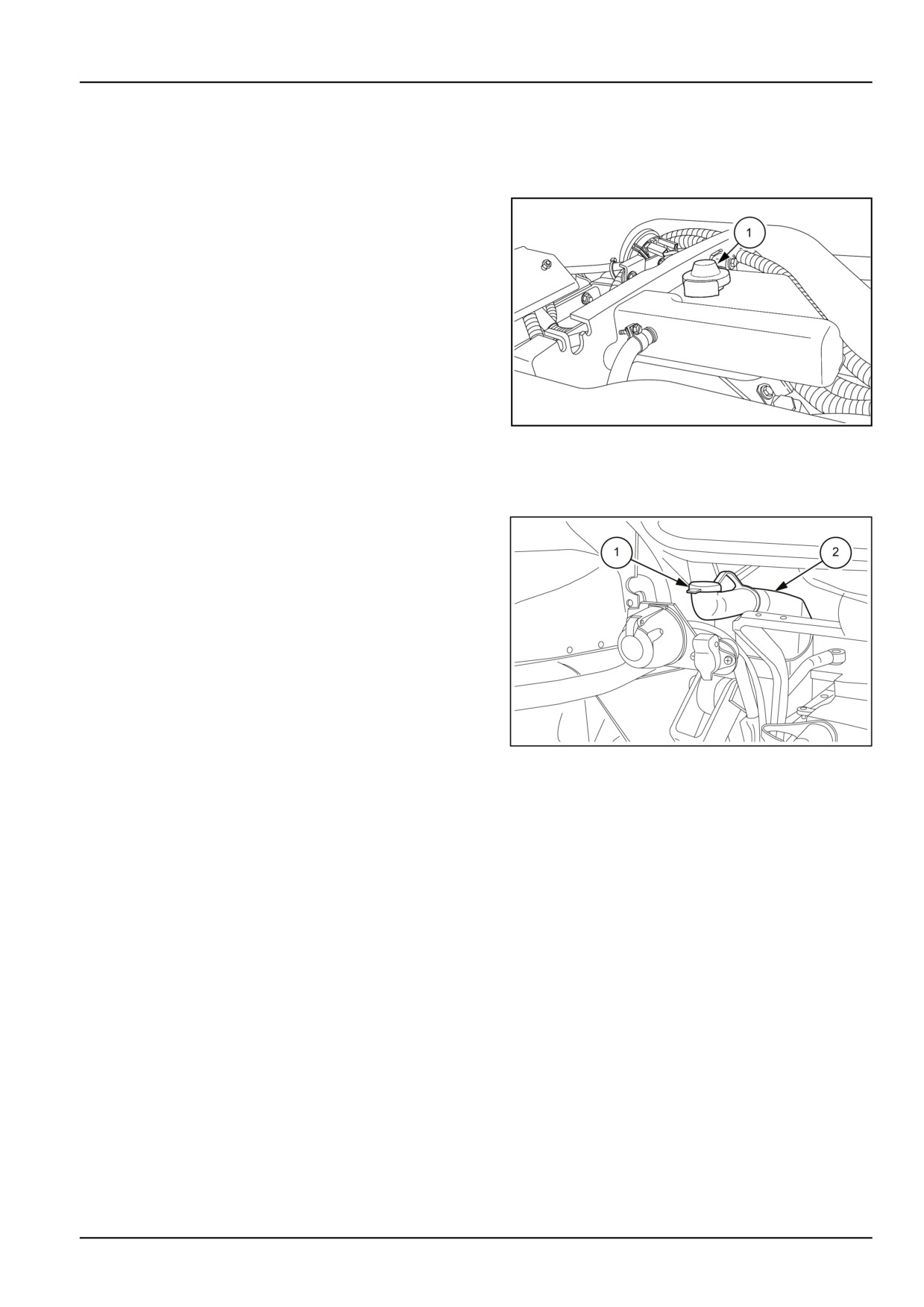
Radiator expansion tank
1. The level must always be above the “ MAX ” mark on
the tank. If necessary, top up to reach the correct level
through the cap (1).
MOIL13TR00948AA
1
Windscreen washer tank
1. To fill−up the windscreen washer tank, remove filler cap
(1) and fill up the tank (2) with washing liquid.
NOTICE: Mix anti−freeze fluid with the water in the winter.
MOIL13TR00793AA
1
Road light - Check
1. Make sure the light beam produced by the various lights
is directed correctly to prevent dazzling drivers of on-
coming vehicles. The procedure for adjusting them is
given further.
7-15
7 - MAINTENANCE
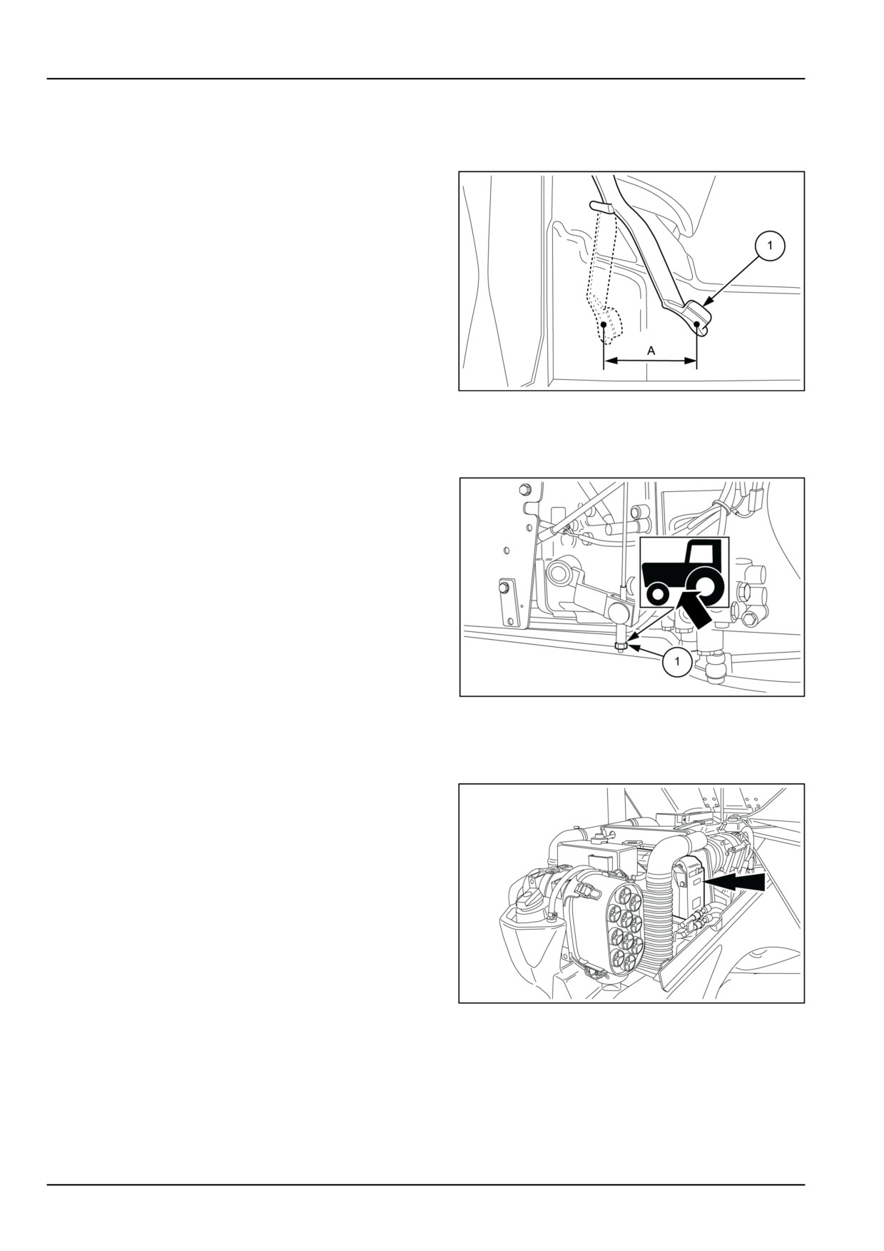
Clutch pedal adjustment
Manual versions
1. If the pedal position becomes uncomfortable (too high)
or it will not reach its upper rest position (to prevent
the clutch slipping), check that distance (A) on pedal
(1) is 150 mm (5.91 in) for tractors without cabs, or
162 mm (6.38 in) for tractors with cabs, if not, contact
your dealer to have it checked and if necessary ad-
justed.
MOIL13TR00633AA
1
Parking brake or parking lock - Adjust
1. When pulled three notches, the parking brake should
engage. If not, tighten the adjustment screw (1) if it
exceeds the three notches or loosen the screw if it fails
to reach the third notch.
MOIL13TR00634AA
1
Radiator - Cleaning
1. Check no dirt has accumulated between the fins and
that they are not obstructed. If any is noted, clean as
follows:
• Slide the air conditioner condensor (where fitted) out
to gain access to the engine coolant radiator.
• For cleaning, use compressed air or a pressure
washer not exceeding 7 bar (101.5 psi).
NOTE: If the cores are blocked with any oily substances,
apply a detergent solution and remove it with a pressure
washer.
NOTICE: If using a pressure washer to wash the radiator,
take care not to direct the jet of water onto the cover of the
MOIL13TR00635AA
1
engine air filter.
7-16
7 - MAINTENANCE
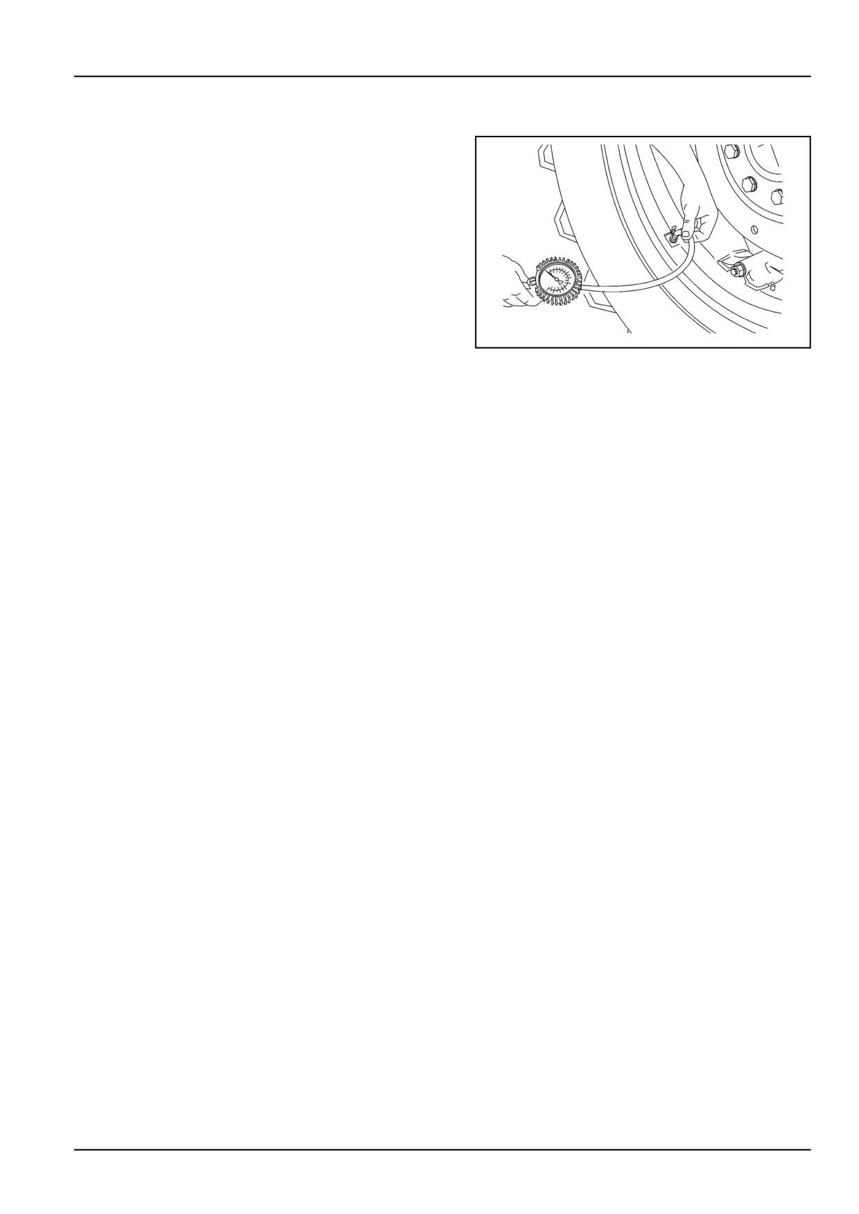
Tyre pressure
1. Connect a pressure gauge to the pressure relief valve
and check it is as prescribed. Check and adjust the
front and rear tire pressures. Inspect the tread and
sidewalls for damage. Adjust the tire pressures to suit
the load being carried. See ‘Tire sizes"’ in Section 5.
NOTE: If the tires are ballasted with a solution of water and
antifreeze, a special tire gauge should be used as the solu-
tion will corrode a proprietary type gauge. Check pressure
with the valve stem at the bottom.
DCAPLNEGB015S4A
1
7-17
7 - MAINTENANCE
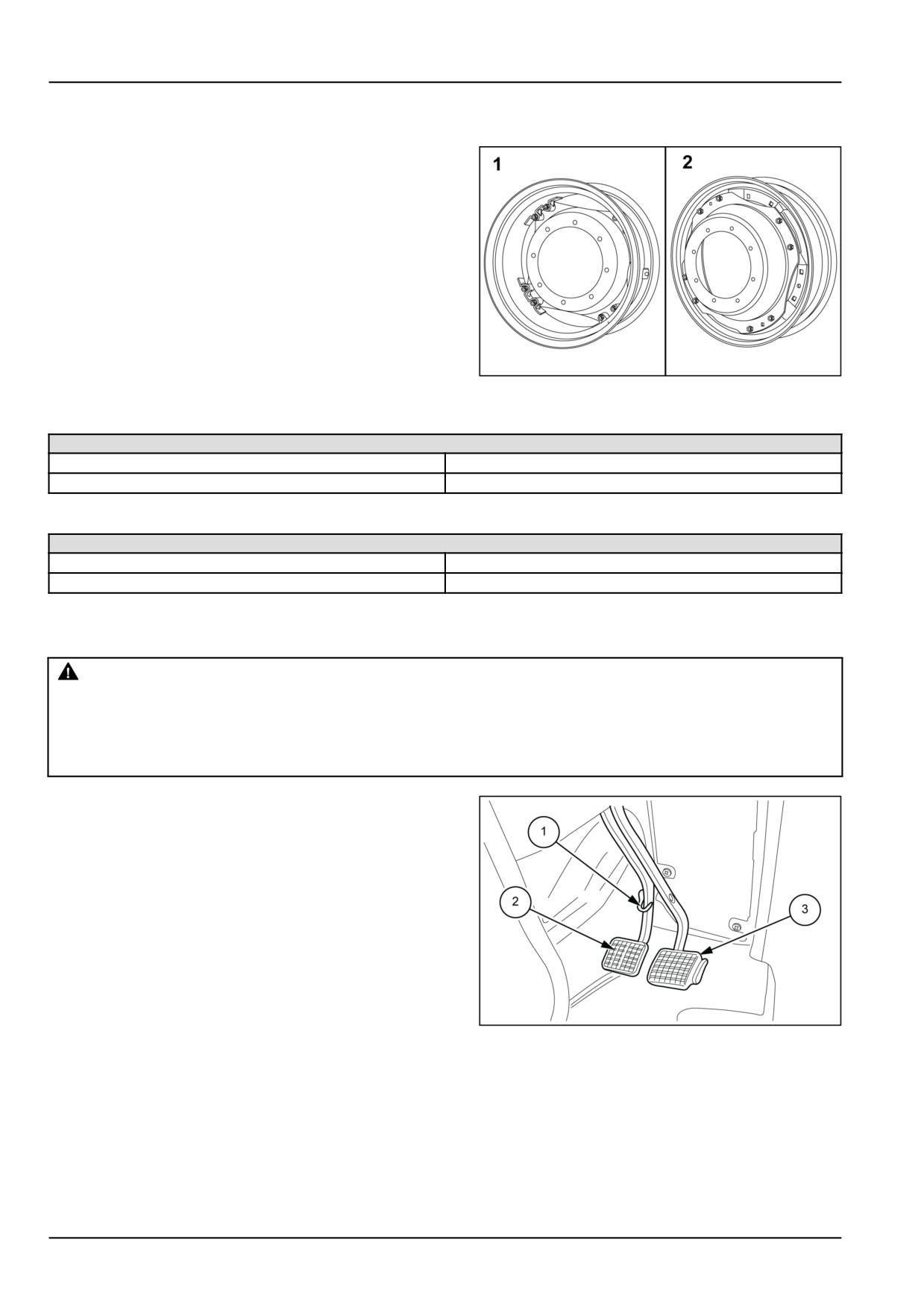
Wheel nuts torque
1. Check the front and rear wheel nuts for tightness using
a torque wrench (with a torque multiplier, where neces-
sary). Always make sure that the front and rear wheels
are symmetrically aligned in relation to the longitudinal
axis of the tractor.
MOIL13TR00011AA
1
Disc to hub nuts
Front and rear wheels
Front — M16
220 N·m (162.3 lb ft)
Rear — M18
310 N·m (228.6 lb ft)
Disc to rim nuts
Front and rear wheels
1
250 - 310 N·m (184.4 - 229 lb ft)
2
280 - 340 N·m (206.5 - 250.8 lb ft)
Brake pedals
WARNING
Equipment failure could cause accident or injury!
Immediately contact your dealer if brake system malfunctions or shows signs of wear, including leak-
age.
Failure to comply could result in death or serious injury.
W0104A
1. See that the pedal joints (2) and (3) and the control
linkage are not damaged. Check that the pin (1) joining
the pedals engages properly as well.
MOIL13TR00636AA
1
7-18
7 - MAINTENANCE
AT WARNING MESSAGE DISPLAY
Engine air filters
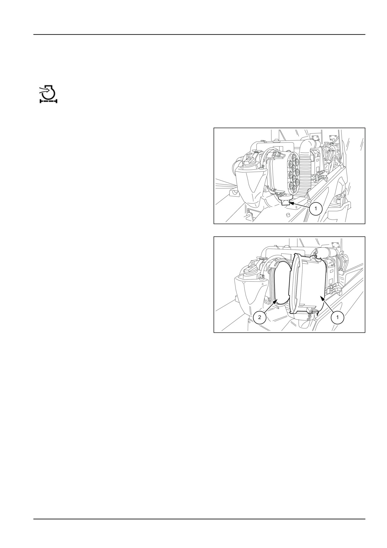
NOTE: When the warning light air filter blocked on the control panel illuminates, check for filter clogging.
Replace the external cartridge every year or when cracks appear (visible by placing a light inside).
Air filter discharge valve
1. Check if the outlet valve (1) is clogged by pressing the
rubber end cap.
MOIL13TR00638AA
1
2. When the warning light air filter blocked on the control
panel illuminates, remove the cover (1), extract the ex-
ternal cartridge (2) and clean as follows;
• place the cartridge facing downwards on a flat sur-
face. Tap on the cartridge with the palm of your hand
a few times, taking care not to damage it, so as to
eliminate any remaining dust.
or
• blow compressed air at a pressure of less than 5 bar
(72.5 psi).
NOTE: It is not advisable to wash the cartridge with water.
MOIL13TR00637AA
2
NOTICE: The internal safety cartridge must never be cleaned or removed when cleaning the external cartridge, but it
must be changed every three times the external cartridge (2) is cleaned.
7-19
7 - MAINTENANCE
Fuel filter water drain
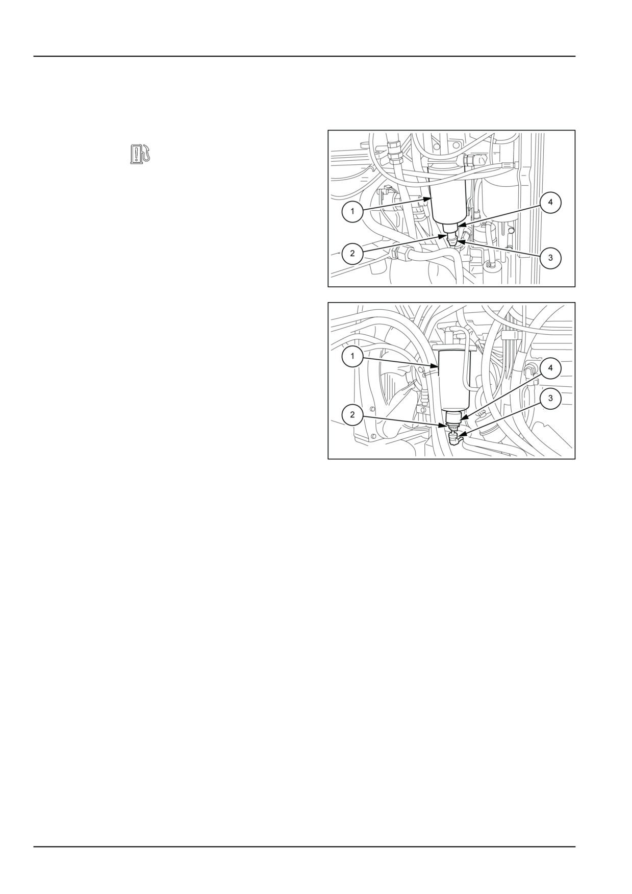
NOTICE: Before loosening or disconnecting any part of the fuel injection system, thoroughly clean the area to be
worked on to prevent contamination.
When the instrument cluster display shows the water
in fuel symbol
, drain the fuel filter (with sedi-
menter) immediately as follows:
1. Place a container under the filter (1);
2. Remove the retaining pin (2) and disconnect the
sensor (3);
3. Remove the drain plug (4) at the base of the filter;
4. Allow contaminated fuel to drain until only clean fuel
runs out. Drain off the fuel and dispose of it appro-
priately. Close the drain plug and replace the sen-
sor wire in position.
MOIL13TR00639AA
1
5. Start the engine running, after a few seconds the
indicator light must go out. If the indicator stays on,
replace the filter even if it has not yet reached the
time for it to be changed.
• Figure 1, models T4.75F and T4.85F
• Figure 2, models T4.95F and T4.105F
MOIL13TR00640AA
2
7-20
7 - MAINTENANCE
Brake fluid level
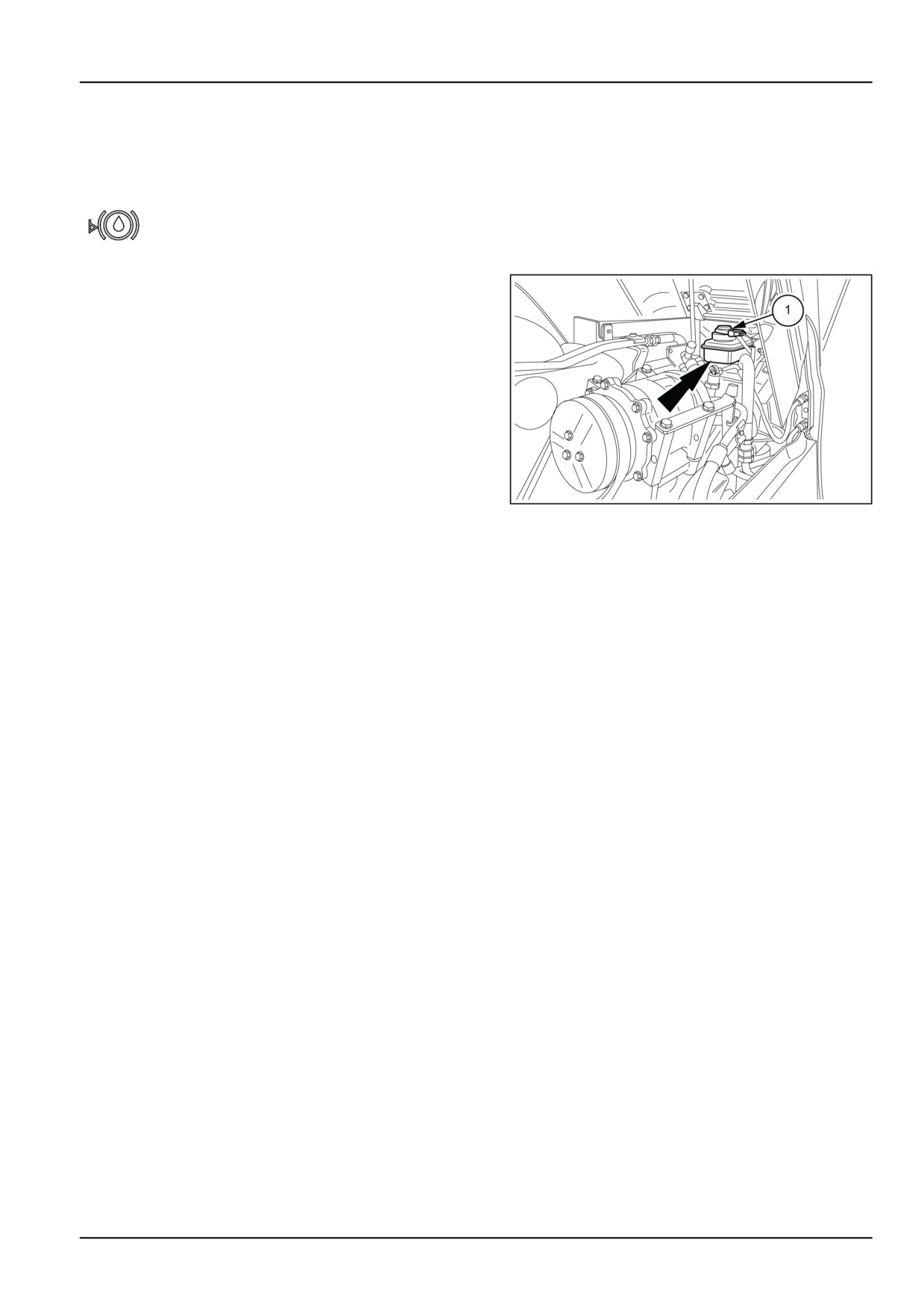
1. Check that the fluid level never drops below the point
marked (MIN) by the arrow on the reservoir.
NOTICE: Illumination of the warning light on the control panel, indicates that the oil level in the reservoir
is below the “MIN” level. Act promptly and restore the level. If the light remains illuminated, contact
your local dealer.
2. Periodically check that the light is working properly. By
pressing the blue push button (1) fig. 1 on the cover, if
all is working correctly, the indicator should illuminate.
NOTICE: Use only the correct type of oil, as shown in
the table "Fluids and lubricants". Mixing different types
of brake fluids may damage the internal hydraulic compo-
nents, thereby compromising braking efficiency. The brake
fluid is of the mineral type, therefore avoid contact with skin.
Carefully read the instructions provided on the fluid con-
tainer.
Do not spill the brake fluid on the tractor as this will damage
the paintwork.
MOIL13TR00641AA
1
7-21
7 - MAINTENANCE
EVERY 10 HOURS OR EACH DAY
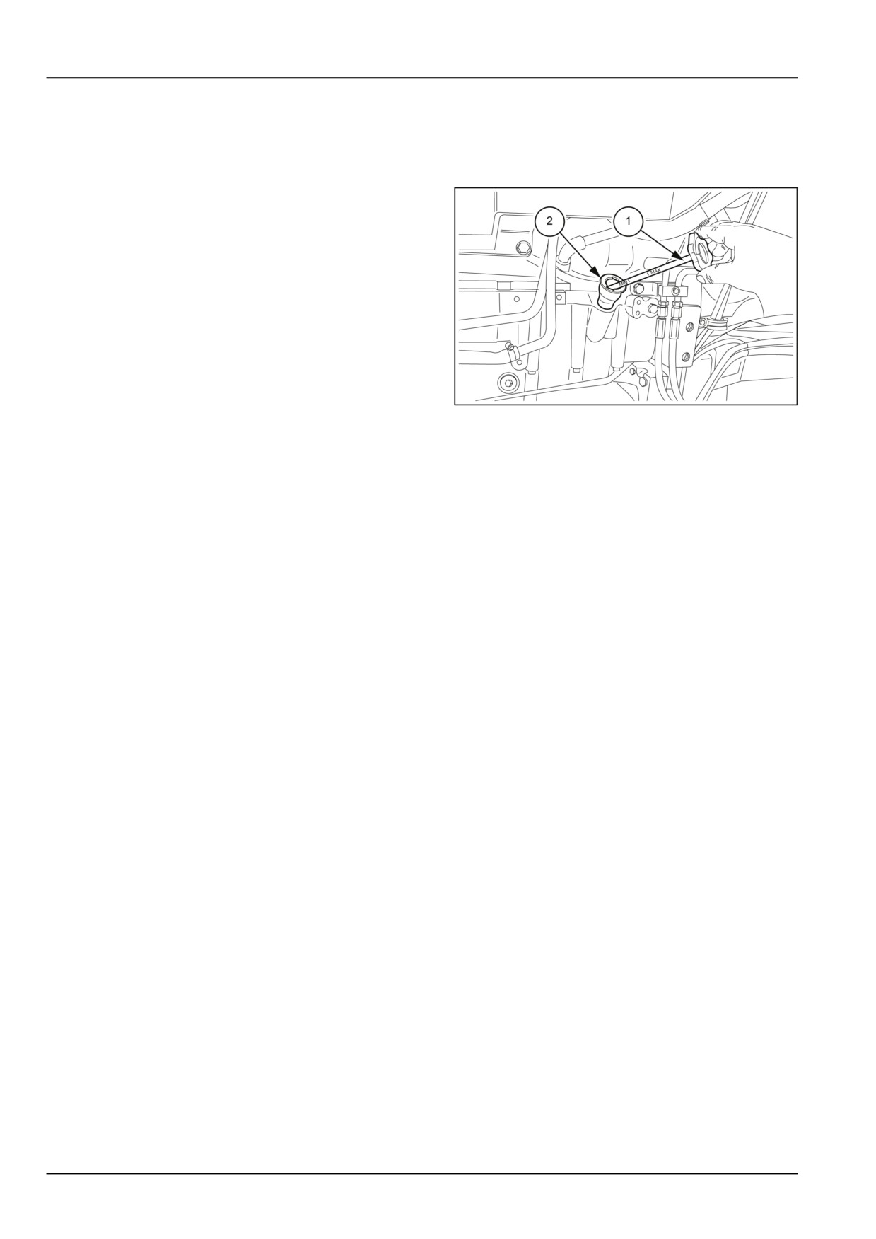
Engine oil level
1. Check the level with the engine on a flat surface with
the engine switched off. Allow at least five minutes for
the oil to settle in the sump:
• Remove the dipstick (1), clean with a cloth and re-
place in the dipstick hole (2).
• Remove the dipstick again and check that the oil
level is between the “MIN” and “MAX” marks.
• If necessary, top up with oil through the fill point (2)
to the required level.
NOTE: The quantity of oil between the “MIN and MAX”
marks on the dipstick is approximately 2 l (0.53 US gal).
MOIL13TR00801AA
1
NOTE: Never run the engine when the oil level is below the
“MIN” mark.
7-22
7 - MAINTENANCE
EVERY 50 HOURS
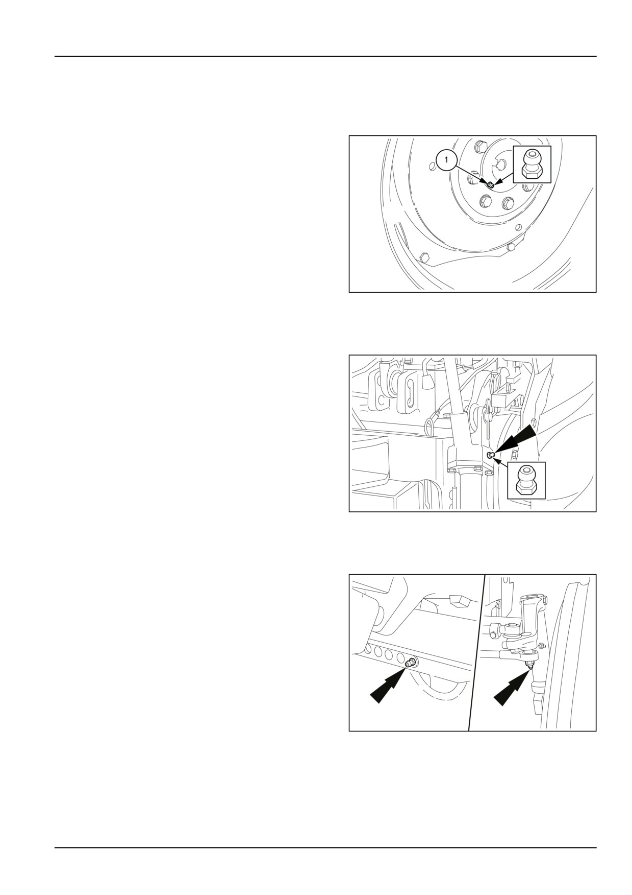
Rear wheel hub
1. Check regularly that when AMBRA GR9 grease is
pumped in via lubricating nipple (1) (one on each
side), grease escapes from the internal guard. To fill
the grease chamber between the wheel hub and the
reducer housing uniformly, the wheel must be turned.
When working in particularly dusty or boggy environ-
ments, the operation must be carried out frequently to
expel any dust or water that has entered.
MOIL13TR00643AA
1
Lift and linkage
1. Using a grease gun, pump NEW HOLLAND AMBRA
GR-9 MULTI-PURPOSE GREASE grease into the lubrica-
tion fitting shown.
MOIL13TR00809AA
1
2WD steering cylinder
1. Using a grease gun, pump NEW HOLLAND AMBRA
GR-9 MULTI-PURPOSE GREASE grease into the lubricat-
ing nipples shown.
MOIL13TR00808AA
1
7-23
7 - MAINTENANCE
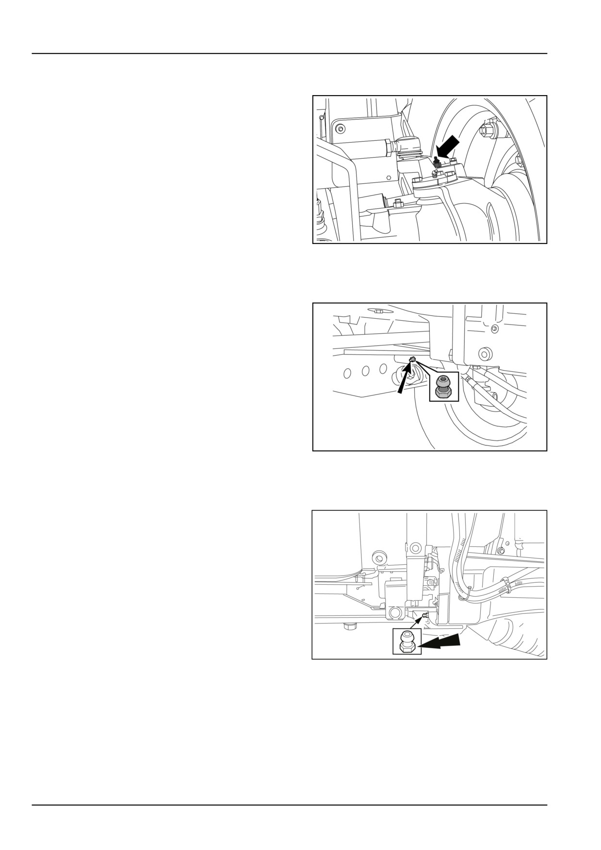
4WD steering cylinders
1. Using a grease gun, pump NEW HOLLAND AMBRA
GR-9 MULTI-PURPOSE GREASE grease into the grease
fittings shown (one on each side).
DCSPFNEGB026S7A
1
2WD front axle pivot
1. Using a grease gun, pump NEW HOLLAND AMBRA
GR-9 MULTI-PURPOSE GREASE grease into the lubricat-
ing nipples shown.
DCSPFNEGB069S4A
1
4WD front axle pivot
1. Using a grease gun, pump NEW HOLLAND AMBRA
GR-9 MULTI-PURPOSE GREASE grease into the lubricat-
ing nipples shown.
MOIL13TR00804AA
1
7-24
7 - MAINTENANCE
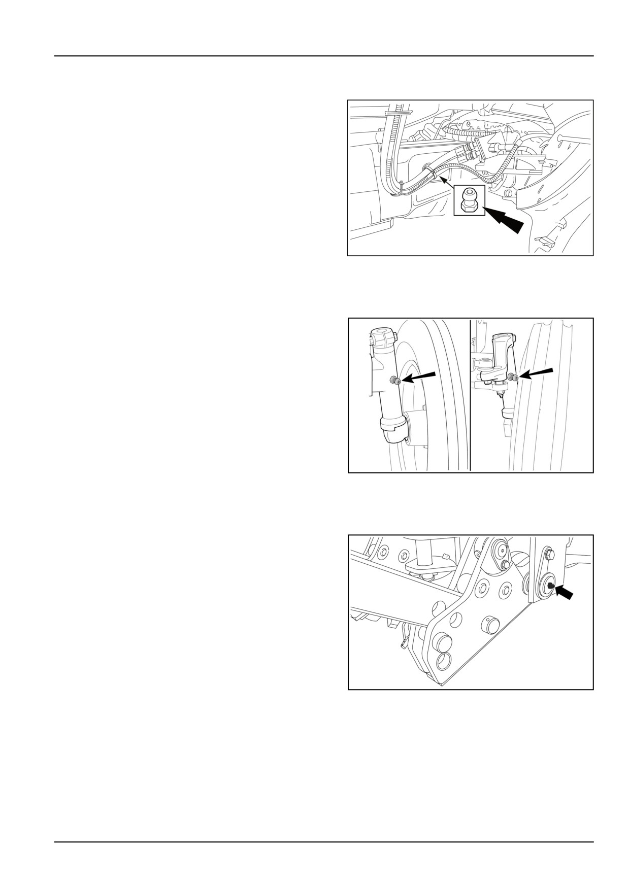
4WD transmission shaft
1. Using a grease gun, pump NEW HOLLAND AMBRA
GR-9 MULTI-PURPOSE GREASE grease into the lubricat-
ing nipples shown.
MOIL13TR00806AA
1
2WD right and left-hand stub axle
1. Using a grease gun, pump NEW HOLLAND AMBRA
GR-9 MULTI-PURPOSE GREASE grease into the lubricat-
ing nipples shown.
DCSPFNEGB070S4A
1
Front lift arms shaft
1. Using a grease gun, pump NEW HOLLAND AMBRA
GR-9 MULTI-PURPOSE GREASE grease into the grease
fitting shown.
DCSPFNEGB027S7A
1
7-25
7 - MAINTENANCE
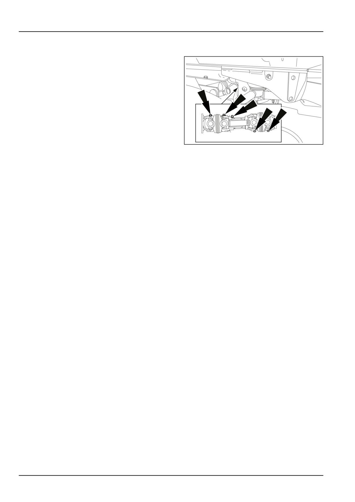
Front PTO coupling
1. Using a grease gun, pump NEW HOLLAND AMBRA
GR-9 MULTI-PURPOSE GREASE grease into the five lu-
bricating nipples shown, located in front of the radiator.
MOIL13TR00815AA
1
7-26
7 - MAINTENANCE
EVERY 100 HOURS
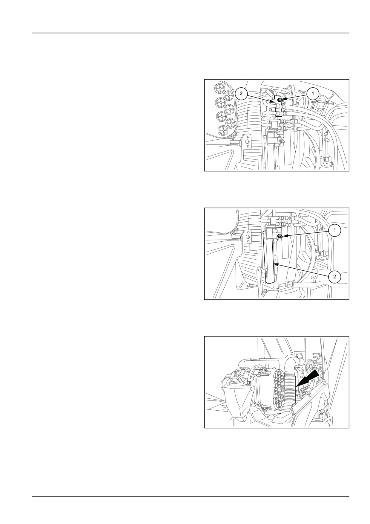
Transmission oil cooler
1. Check no dirt has accumulated on the fins and that they
are not obstructed. If cleaning is necessary, release the
catch (1), take out the cooler (2), and clean it as follows:
Remove the protective mesh on the cooler and direct
the jet of air or water through each fin, from the back to
the front. Carefully straighten any bent fins.
MOIL13TR00651AA
1
Air conditioning condenser
1. Free the catch (1), extract the condenser (2) of the
air−conditioning system from its housing. Remove the
protective mesh and clean it of any dirt that accumu-
lates between the cooling fins. Check that the fins are
not deformed then restore proper working conditions.
NOTE: If you notice any operating trouble with the air−con-
ditioning system, have the drier filter housed under the cab
roof checked by your dealer’s specialized personnel.
MOIL13TR00652AA
1
Intercooler
1. Remove the air−conditioning system condenser from
its housing shown in figure. Clean the intercooler with
a jet of air or water from the back towards the front.
NOTICE: If using a pressure washer to wash the compo-
nents, take care not to direct the jet of water onto the cover
of the engine air filter.
MOIL13TR00653AA
1
7-27
7 - MAINTENANCE
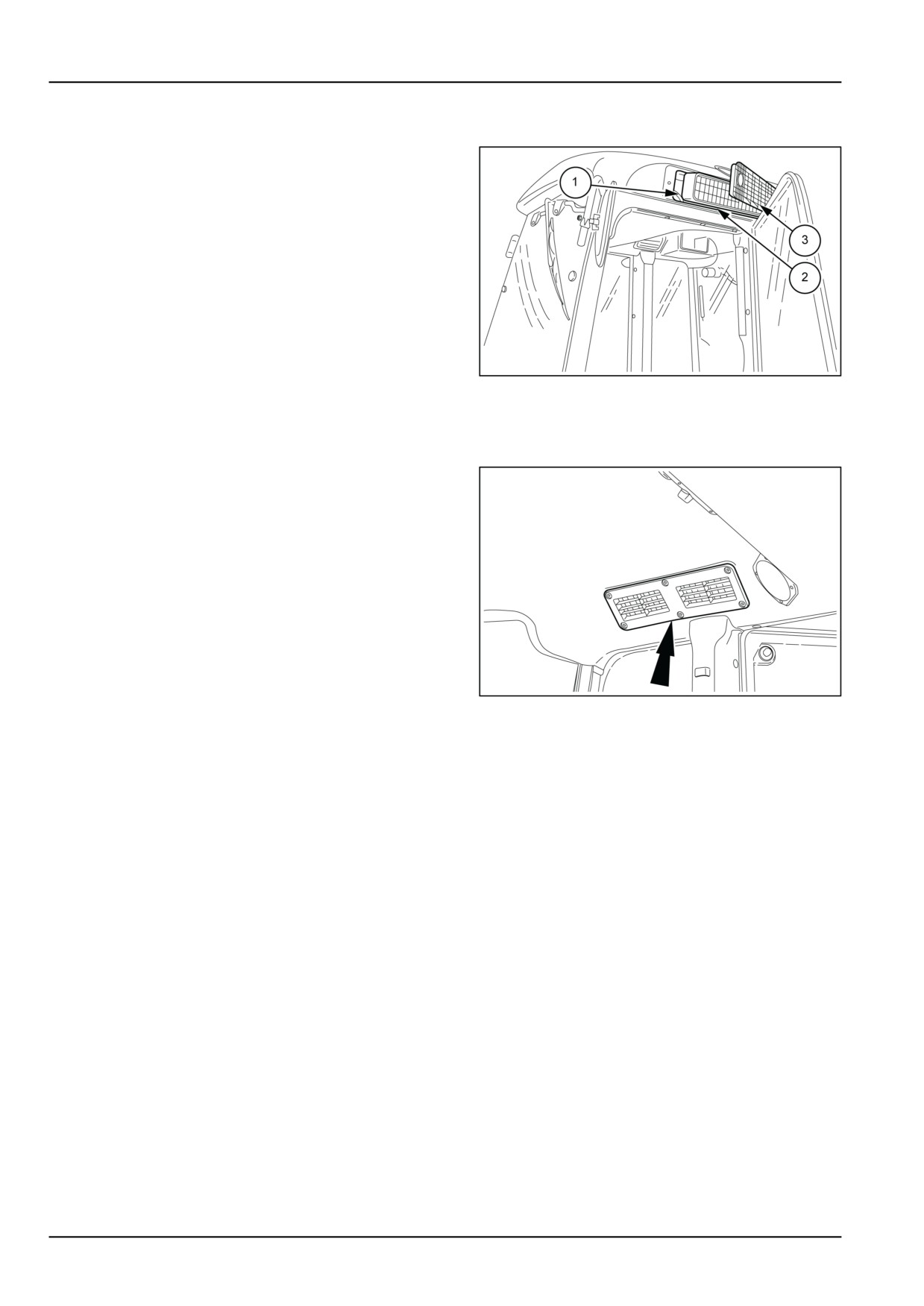
Cab air filter
1. Open the wire mesh guards (3), extract the cartridges
(2) and clean them:
by tapping gently on a flat surface with the outward−
facing part downwards;
or
with a jet of compressed air at a pressure of less than
6.9 bar (100 psi)100.05 psi (6.9 bar);
Clean the filter seats (1) with a cloth. When refitting,
make sure the arrows on the cartridge labels are point-
ing towards the inside of the cab.
MOIL13TR00654AA
1
Cab recirculated air filter
1. Remove the grilles on either side of the cab and clean
the recirculated air cartridges located in the housings.
MOIL13TR00655AA
1
7-28
7 - MAINTENANCE
EVERY 300 HOURS
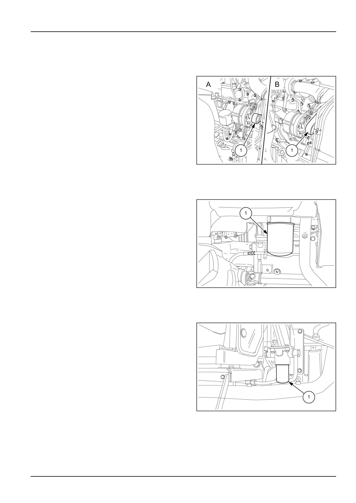
Alternator belt
Contact your dealer’s specialized personnel and have the
tension of the alternator belt (1) checked. Check that the
belt is not cracked and shows no signs of rubbing; fit a new
belt if there is any doubt. Ensure that the belt is correctly
located on the pulleys and that the belt tensioner is oper-
ating correctly.
A. T4.75F - T4.85F
B. T4.95F - T4.105F
MOIL13TR00656AA
1
Transmission oil filter
1. Unscrew the container (1) and replace the internal filter.
Before re−positioning the container, oil the seals and
screw on by hand for 3/4 of a turn. Top up with new oil.
MOIL13TR00658AA
1
Oil filter models with power shuttle/dual command
1. Replace the filter (1) located on the right-hand side of
the tractor. Oil the seal, screw on and tighten the car-
tridge 3/4 of a turn by hand. Top up the oil level, without
using old oil.
MOIL13TR00825AA
1
7-29
7 - MAINTENANCE
Engine air filters
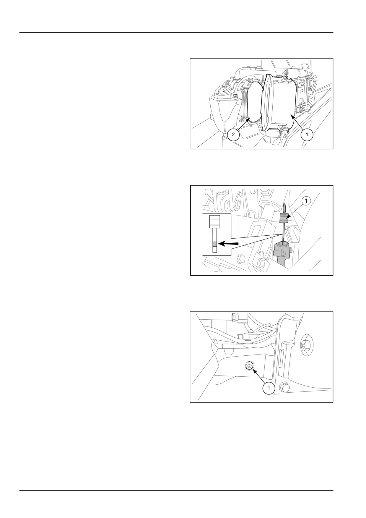
1. Remove the cover (1), extract the external cartridge (2)
and clean (see operation described on 7-19).
NOTICE: The internal safety cartridge must never be
cleaned or removed when cleaning the external cartridge,
but it must be changed every three times the external
cartridge (2) is cleaned.
MOIL13TR00637AA
1
Transmission oil level
1. With the tractor on a level surface, the engine switched
off and the lift arms lowered, check that the oil level
reaches the upper mark on the dipstick (1). If neces-
sary, top up with oil through the dipstick hole. (for quan-
tity and type see "Refuelling table" in this section)
NOTE: If the tractor is fitted with a front lift, make sure that
the lift arms are lowered before checking the transmission
oil.
DCSPFNEGB071S4A
1
4WD front axle housing
1. Check the oil level as follows:
• Park the tractor on a level surface.
• Remove the plug (1), the oil will flow out of the plug
hole.
• If necessary, top up via plug hole (1) until oil escapes.
NOTICE: for quantity and type see "Refuelling table" in this
section.
MOIL13TR00828AA
1
7-30
7 - MAINTENANCE
4WD front axle final drives
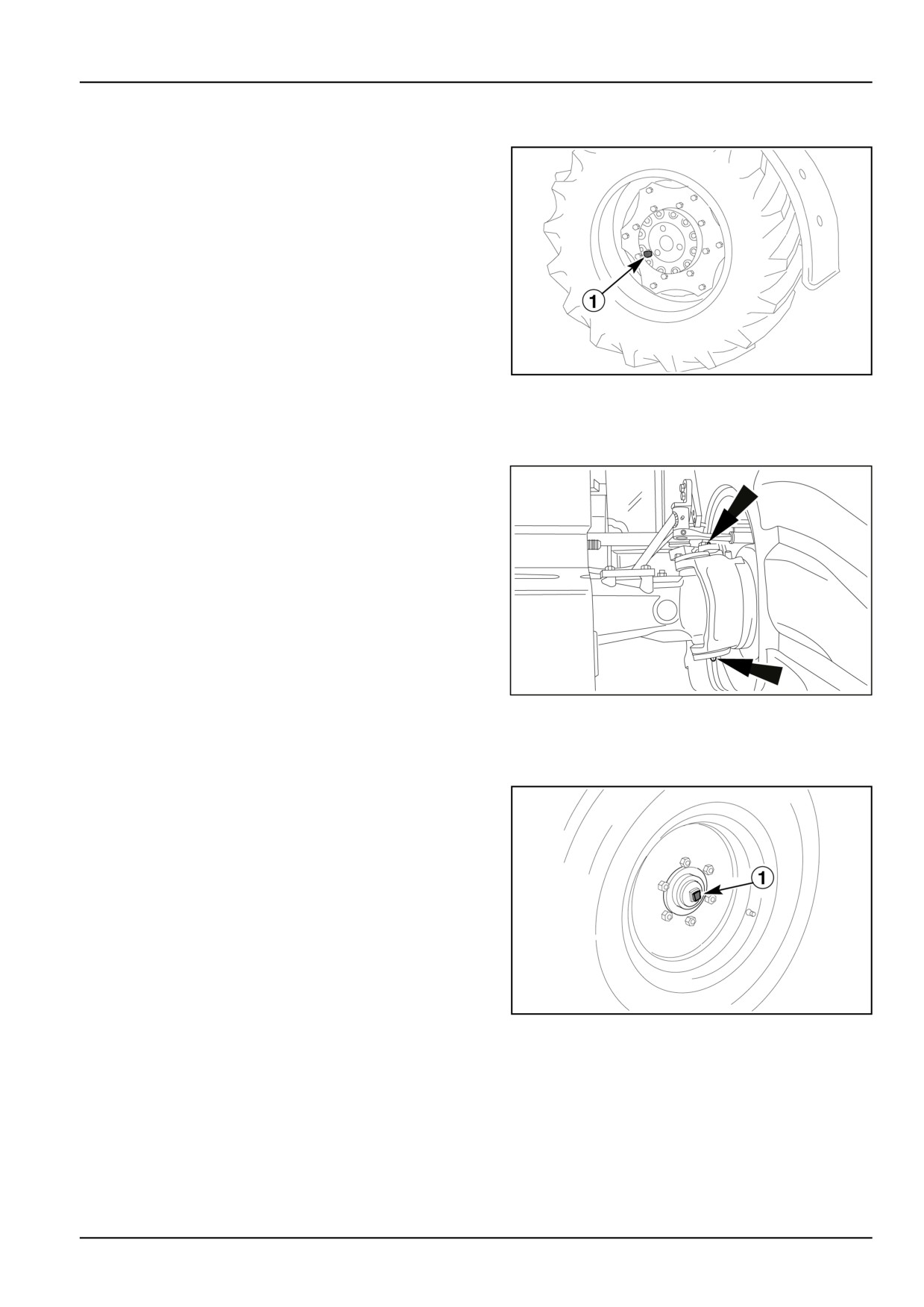
1. Bring the plug (1) to a horizontal position and check
the oil level. If oil does not come out of the plug, top up
through the plug hole.
NOTICE: for quantity and type see "Refuelling table" in this
section.
DCSPFNEGB072S4A
1
4WD front axles stub
1. Inject NEW HOLLAND AMBRA GR-9 MULTI-PURPOSE
GREASE grease in the two nipples shown (two on each
side).
MOIL13TR00830AA
1
2WD front wheels
1. Remove the hub covers (1) and fill with NEW HOL-
LAND AMBRA GR-9 MULTI-PURPOSE GREASE, then re-
place the covers.
DCSPFNEGB073S4A
1
7-31
7 - MAINTENANCE
EVERY 500 HOURS
Engine oil and filter
T4.75F — T4.85F
NOTE: This operation describes the process of draining oil from the engine sump and changing the relevant oil filter.
The frequency of 500 hours can anyhow be affected by other factors:
Cold temperature operation
Engines operating in temperatures below -12 °C (10.4 °F)
or in arduous conditions should have the oil changed every
300 hours of operation. The filter must be changed regu-
larly as prescribed.
Diesel fuel sulphur content
In some countries, locally available diesel may have a high
sulphur content, in which case the oil and filter should be
changed sooner, as follows:
Sulphur content between 0,5 - 1,0 % change oil every 300
hours;
Sulphur content between 1,0 - 1,3 % change oil every 150
hours;
If in doubt, or if it is not possible to check the instructions
MOIL13TR00833AA
1
given, keep to the interval recommended in the Operator’s
Manual.
Drain oil and renew filter
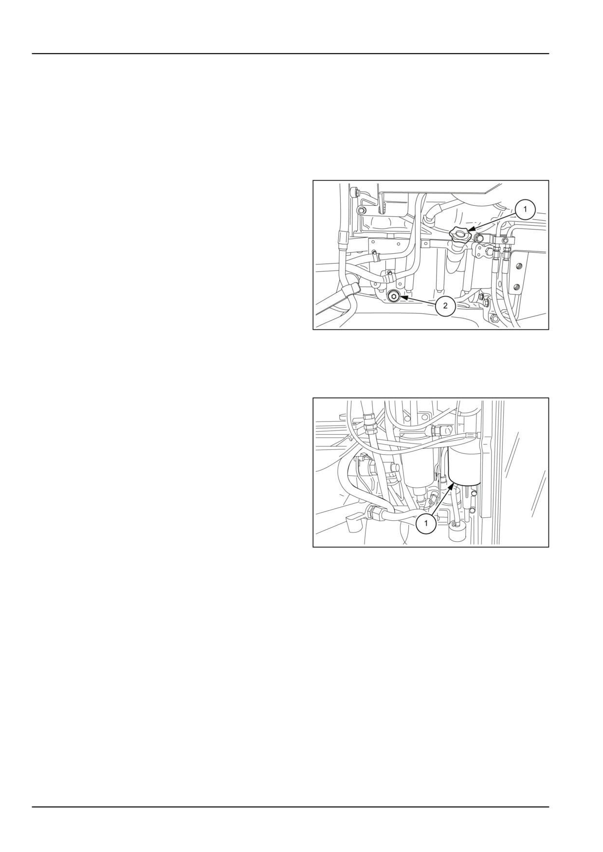
• place a container under the engine sump;
• remove the drain plugs (2) figure 1 from the sump
(one on each side) and drain off the oil;
• screw the plugs back on;
• unscrew the filter (1) figure 2, drain it of the remaining
oil and discard it as required by the current regula-
tions in your country;
• clean the surface of the filter seat;
• lightly oil the seal of the new filter, screw it down into
contact with the support and tighten it by hand by 3/4
of a turn, or a full turn at most;
fill up with new oil through the fill point (1) figure 1
MOIL13TR00666AA
2
• start the engine, leave it idling for at least 3 minutes;
switch it off and check that the oil level is between the
MIN and MAX marks on the dipstick. If necessary,
top up with oil.
7-32
7 - MAINTENANCE
Fuel filter
T4.75F — T4.85F
NOTICE: Before loosening or removing any components of the injection system carefully clean the area around the
components involved in the maintenance work to prevent contaminating the system.
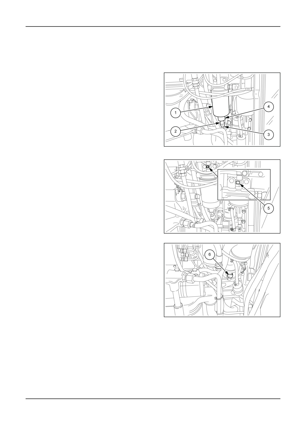
To change the filter, proceed as follows:
• Place a container under the filter (1);
• Remove the retaining pin (2) and disconnect the sen-
sor (3);
• Unscrew the drain plug (4) at the base of the filter to
drain off the fuel;
• remove the filter cartridge (1);
• lightly oil the seal, screw the new cartridge down into
contact with the support and tighten it by hand by 3/4
of a turn ( 15 N·m);
• fit the sensor (3) back on and secure it with the re-
MOIL13TR00667AA
1
taining pin (2).
After changing the filter cartridge, it is necessary to
bleed the fuel system as follows:
• press the two retaining buttons (5) (one is behind the
union) and disconnect the pipe from the filter head;
• pump the primer lever (6) until the fuel coming out of
the filter contains no air bubbles;
• refit the pipe by simply pushing it downwards to lock
it on the head of the filter.
MOIL13TR00668AA
2
MOIL13TR00669AA
3
7-33
7 - MAINTENANCE
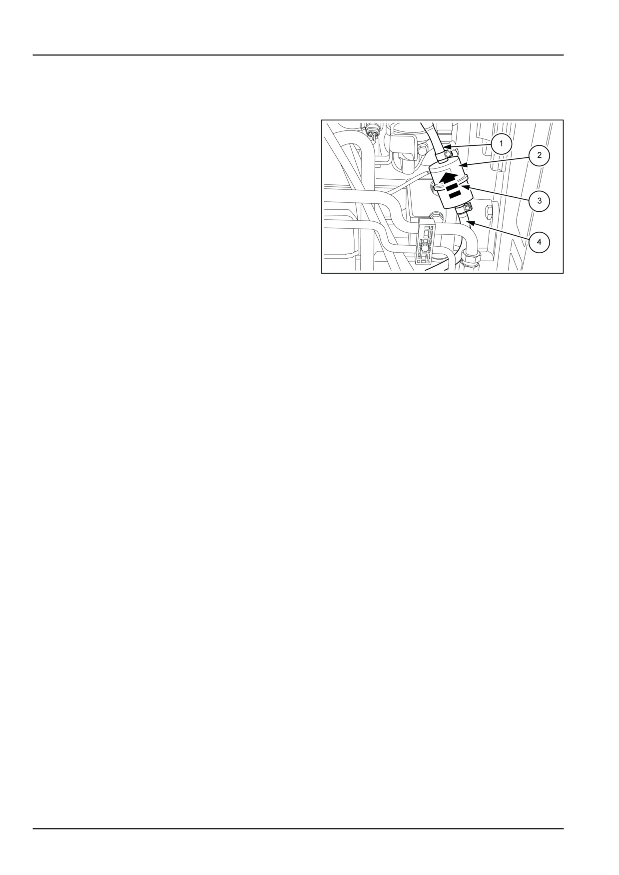
Fuel pre-filter
T4.75F — T4.85F
1. Check periodically to ensure that the filter container (2)
is clean. If it needs cleaning, proceed as follows;
• First detach pipe (4) from the fuel tank and then pipe
(1);
• remove the filter and blow compressed air in the op-
posite direction to the arrow (3) on the container in
order to remove the material deposited inside.
NOTE: If after cleaning you notice that the filter is still dirty,
then it needs replacing.
MOIL13TR00670AA
1
NOTICE: The arrow (3) on the transparent plastic container indicates the direction of the flow of diesel. When you fit
the filter back on, first fill it with diesel and take care that the arrow (3) faces the direction of the fuel pump as illustrated.
When you fit the pipes (1) and (4) back on make sure that the clamps are in contact with the filter so as to ensure
correct tightening, which prevents air getting into the circuit
7-34
7 - MAINTENANCE
EVERY 600 HOURS
Engine oil and filter
T4.95F — T4.105F
NOTE: This operation describes the procedures for draining oil from the engine sump and changing the relevant oil
filter. The frequency of 600 hours can anyhow be affected by other factors:
Cold temperature operation
Engines operating in temperatures below -12 °C (10.4 °F)
or in arduous conditions should have the oil changed every
300 hours of operation. The filter must be changed regu-
larly as prescribed.
Diesel fuel sulphur content
In some countries, locally available diesel may have a high
sulphur content, in which case the oil and filter change pe-
riod should be adjusted, as follows:
sulphur content between 0,5 - 1,0 %, change the engine oil
every 300 hours;
sulphur content between 1,0 - 1,3 %, change the engine oil
every 150 hours;
If in doubt, or it it is not possible to check these indications,
MOIL13TR00833AA
1
keep to the frequency recommended in the use and main-
tenance manual.
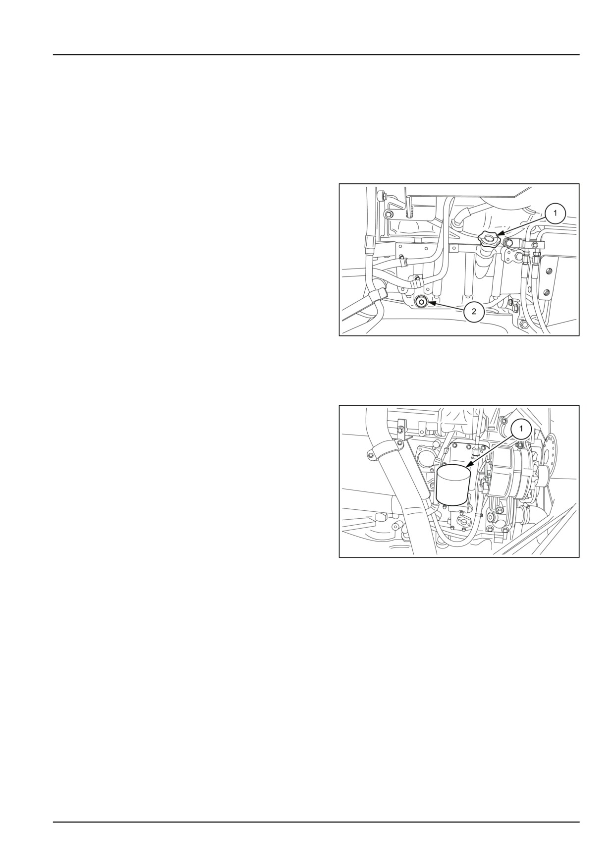
Drain oil and renew filter
• place a container under the engine sump;
• remove the drain plugs (2), figure 1, from the sump
(one on each side) and drain off the oil;
• screw the plugs back on;
• unscrew the filter (1), figure 2, drain off the remaining
oil and discard it as required by current regulations
in your country;
• clean the surface of the filter seat;
• lightly oil the seal of the new filter, screw it down into
contact with the support and tighten it by hand by 3/4
of a turn, or a full turn at most;
fill with fresh oil through the filler (1), figure 1
MOIL13TR00672AA
2
• start the engine, leave it idling for at least 3 minutes;
switch it off and check that the oil level is between the
MIN and MAX marks on the dipstick. If necessary,
top up with oil.
7-35
7 - MAINTENANCE
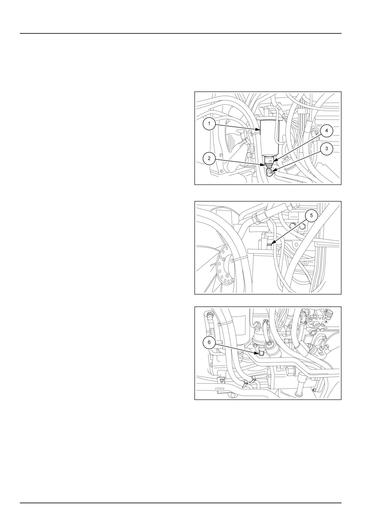
Fuel filter
T4.95F — T4.105F
NOTICE: Before loosening or removing parts of the injection system, thoroughly clean the area surrounding the com-
ponents involved in the maintenance work in order to avoid contaminating the system.
To change the filter, proceed as follows:
• Place a container under the filter (1);
• Remove the retaining pin (2) and disconnect the sen-
sor (3);
• Unscrew the drain plug (4) at the base of the filter to
drain off the fuel;
• remove the filter cartridge (1);
• Lightly oil the seal, screw on the new cartridge into
contact with the support and tighten it by hand by 3/4
of a turn ( 15 N·m);
• Fit the sensor (3) back on and secure it with the re-
MOIL13TR00840AA
1
taining pin (2).
After changing the filter cartridge, it is necessary to
bleed the fuel system as follows:
• press the two retaining buttons (5) (one is behind the
fitting) and disconnect the pipe from the filter head;
• pump the primer lever (6) until the fuel coming out of
the filter contains no air bubbles;
• reconnect the pipe by simply pressing it downwards
to lock it in position on the head of the filter.
MOIL13TR00842AA
2
MOIL13TR00845AA
3
7-36
7 - MAINTENANCE
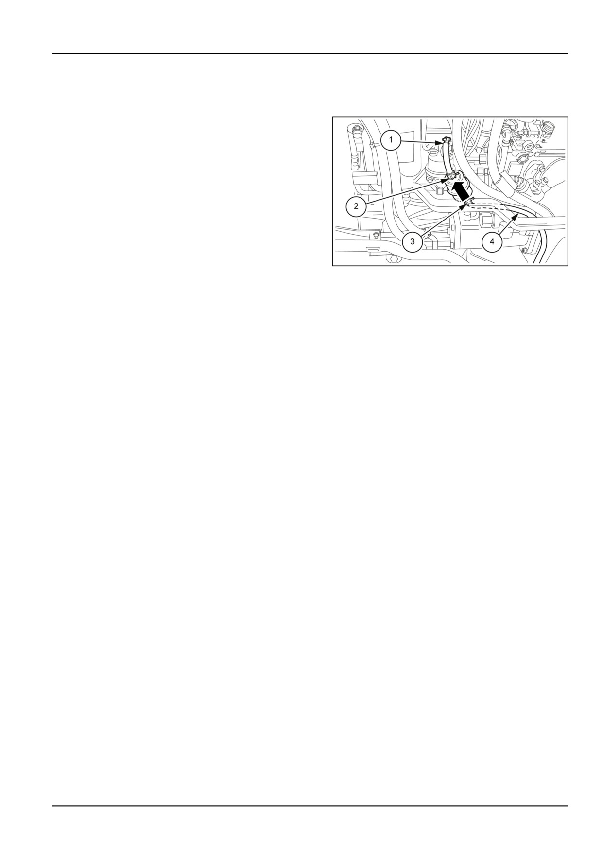
Fuel pre-filter
T4.95F — T4.105F
1. Check periodically to ensure that the filter container (2)
is clean. If it needs cleaning, proceed as follows;
• first detach the pipe (4) from the fuel tank, then the
pipe (1);
• remove the filter and blow compressed air in the op-
posite direction to the arrow (3) on the container in
order to remove the material deposited inside.
NOTE: If after cleaning you notice that the filter is still dirty,
then it needs replacing.
MOIL13TR00847AA
1
NOTICE: The arrow (3) on the transparent plastic container indicates the direction of the flow of diesel. When you fit
the filter back on, first fill it with diesel and take care that the arrow (3) faces the direction of the fuel pump as illustrated.
When you fit the pipes (1) and (4) back on, make sure that the clamps are in contact with the filter so as to ensure
correct tightening, which prevents air getting into the circuit
7-37
7 - MAINTENANCE
EVERY 1200 HOURS OR ANNUALLY
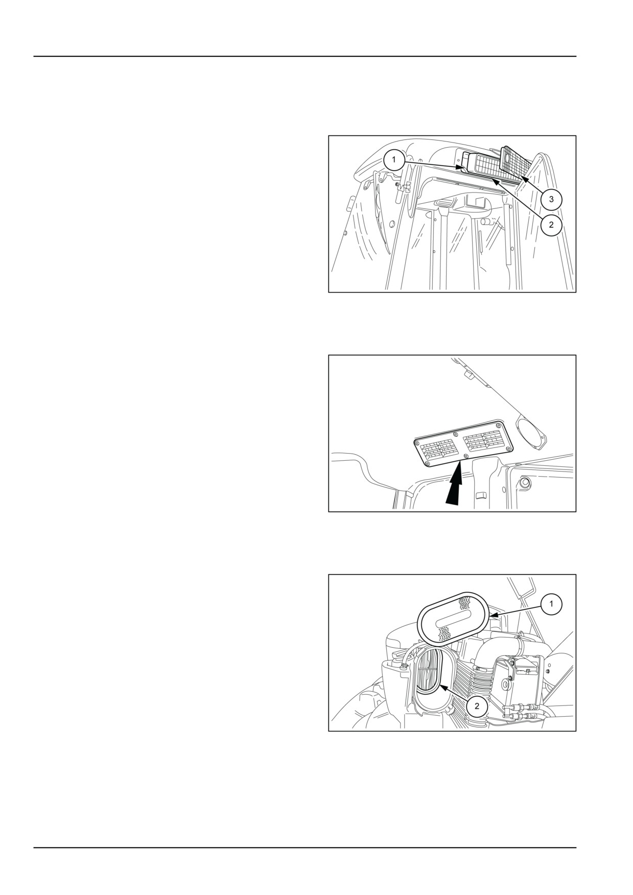
Cab air filters
1. Remove the grilles (3), one on each side, and replace
the internal cartridges (2). Before fitting new cartridges,
clean the seats (1) with a damp cloth.
NOTE: In this phase it is necessary to replace the active
carbon filters too.
MOIL13TR00654AA
1
Cab recirculated air filter
1. Remove the grilles on either side of the cab and clean
the recirculated air cartridges located in the housings.
MOIL13TR00655AA
1
Engine air filters
1. Replace the external filter (1), together with the internal
filter (2).
NOTE: Never clean the internal safety cartridge. Replace
together with the external cartridge.
MOIL13TR00677AA
1
7-38
7 - MAINTENANCE
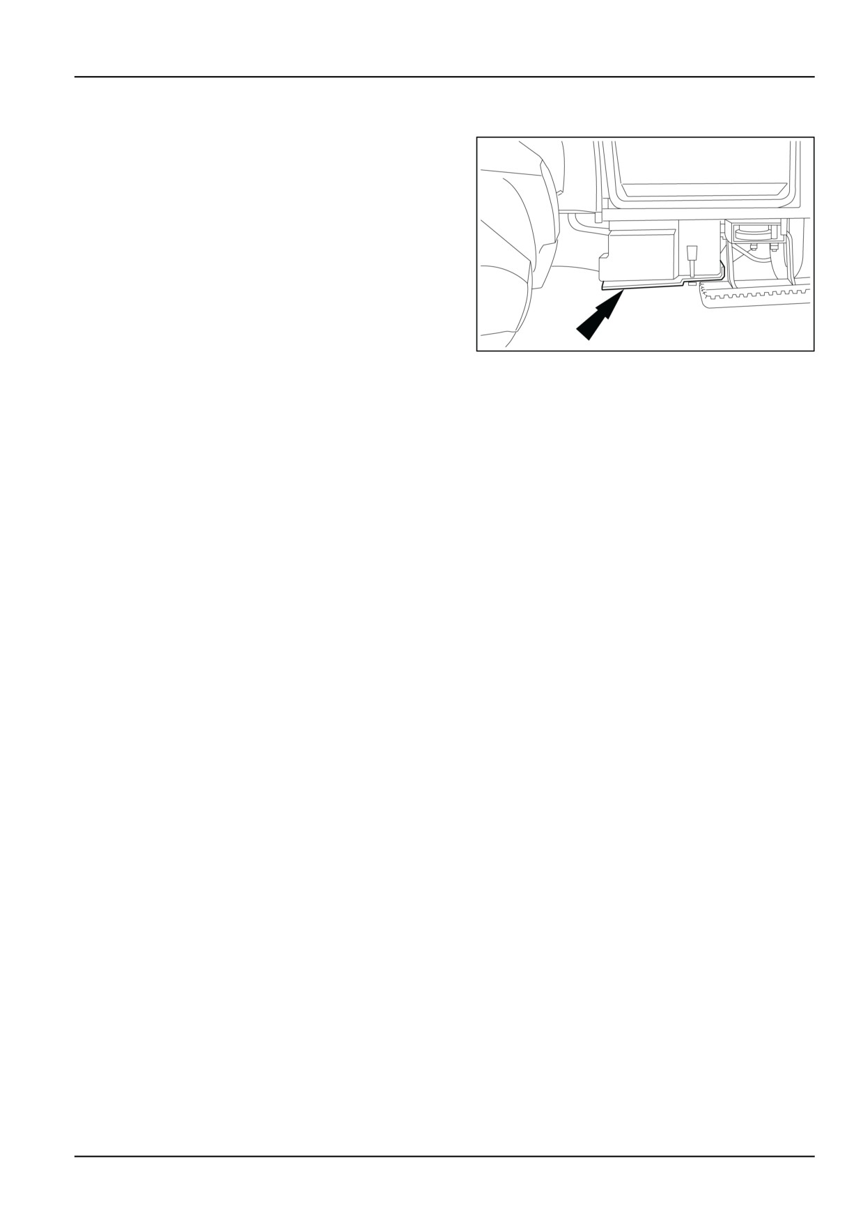
Fuel tank
1. With the tractor on a level surface and the engine off,
drain the fuel as described below:
• place a container under the tank;
• remove the plug and drain the fuel to eliminate any
impurities in the tank.
• Refill the tank with clean fuel and bleed the system,
as described on 7-33
MOIL13TR00678AA
1
7-39
7 - MAINTENANCE
EVERY 1200 HOURS OR EVERY 2 YEARS
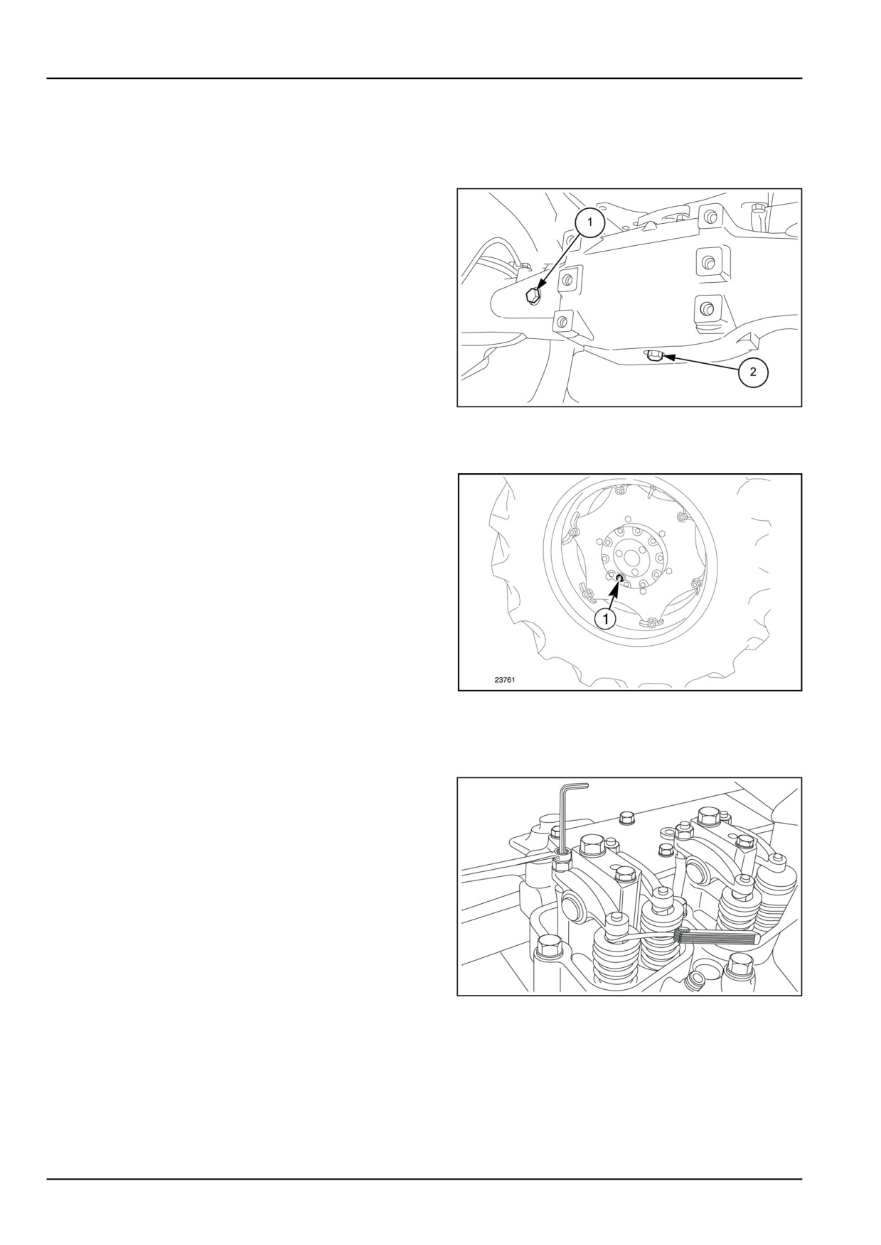
4WD front axle housing
1. Place a container under the axle housing, unscrew the
screw (2), and let all of the oil drain out. Fill up with new
oil through the plug (1).
NOTICE: for quantity and type see "Refuelling table" in this
section.
MOIL13TR00982AA
1
Draining the oil from the front axle final drives
2. Position plug (1) to its lowest point, place a container
under the plug hole and drain the oil. Return the plug
hole to a horizontal position and fill with new oil. The oil
reservoir is full when oil starts to come out of the hole.
NOTICE: for quantity and type see "Refuelling table" in this
section.
DCUTDNEGB084S4A
2
Engine valves
1. Contact authorised personnel at your local dealer to
check the clearance between the valves and the rocker
arms.
MOIL13TR00681AA
1
7-40
7 - MAINTENANCE
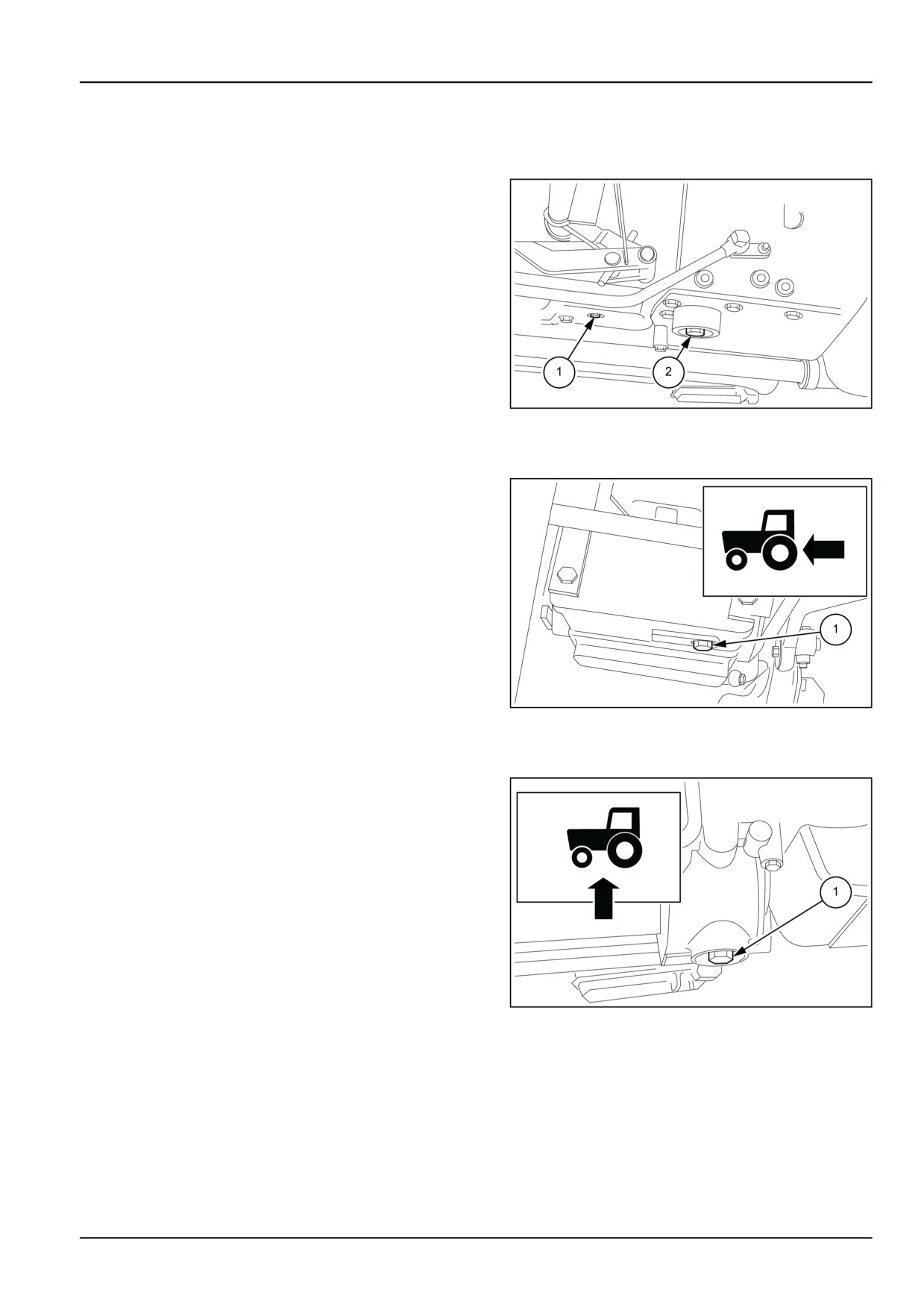
Change transmission oil
Transmission housing
1. Place a container under the plug holes (1) and (2) and
drain off the oil.
MOIL13TR00682AA
1
Lift torsion bar
2. Place a container under the drive gear housing and
drain off the oil through the plug hole (1).
MOIL13TR00683AA
2
Drive gear, 4−wheel drive
3. Place a container under the drive gear housing and
drain off the oil through the plug hole (1). After the oil
has drained off, screw on the plugs and fill up with new
oil through the dipstick hole.
NOTE: Replace the filter every time transmission and lift
oil is changed.
MOIL13TR00684AA
3
7-41
7 - MAINTENANCE
Washing cooling system
CAUTION
Burn hazard!
Hot coolant can spray out if you remove the filler cap while the system is hot. After the system has
cooled, turn the filler cap to the first notch and wait for all pressure to release before proceeding.
Failure to comply could result in minor or moderate injury.
C0043A
WARNING
Chemical hazard!
Coolant can be toxic. Keep away from children and pets. Avoid prolonged contact. If not reused,
dispose of in accordance with local environmental regulations.
Failure to comply could result in death or serious injury.
W0295A
The system uses a mixture of water and FLEETGUARD® COMPLEAT™ antifreeze fluid. This liquid has anti-oxidant,
anti-corrosive, anti-foaming and anti-crusting properties; it is also non-freezing to temperatures of
Degrees
-8 °C (17.6 °F)
-15 °C (5.0 °F)
-25 °C (-13.0 °F)
-30 °C (-22.0 °F)
% by volume of liquid
20
30
40
50
1. Filling the circuit when you buy the tractor will guaran-
tee the system against minimum temperatures above
those shown on the plate attached to the hood.
This mixture can be kept unchanged for a period of 2
years provided that during this time the tractor has not
been used for more than 1200 hours, in total, in which
case it must be replaced when the system is flushed.
In an emergency situation, in the event of unexpected
leaks, fill up the system with water through the radiator
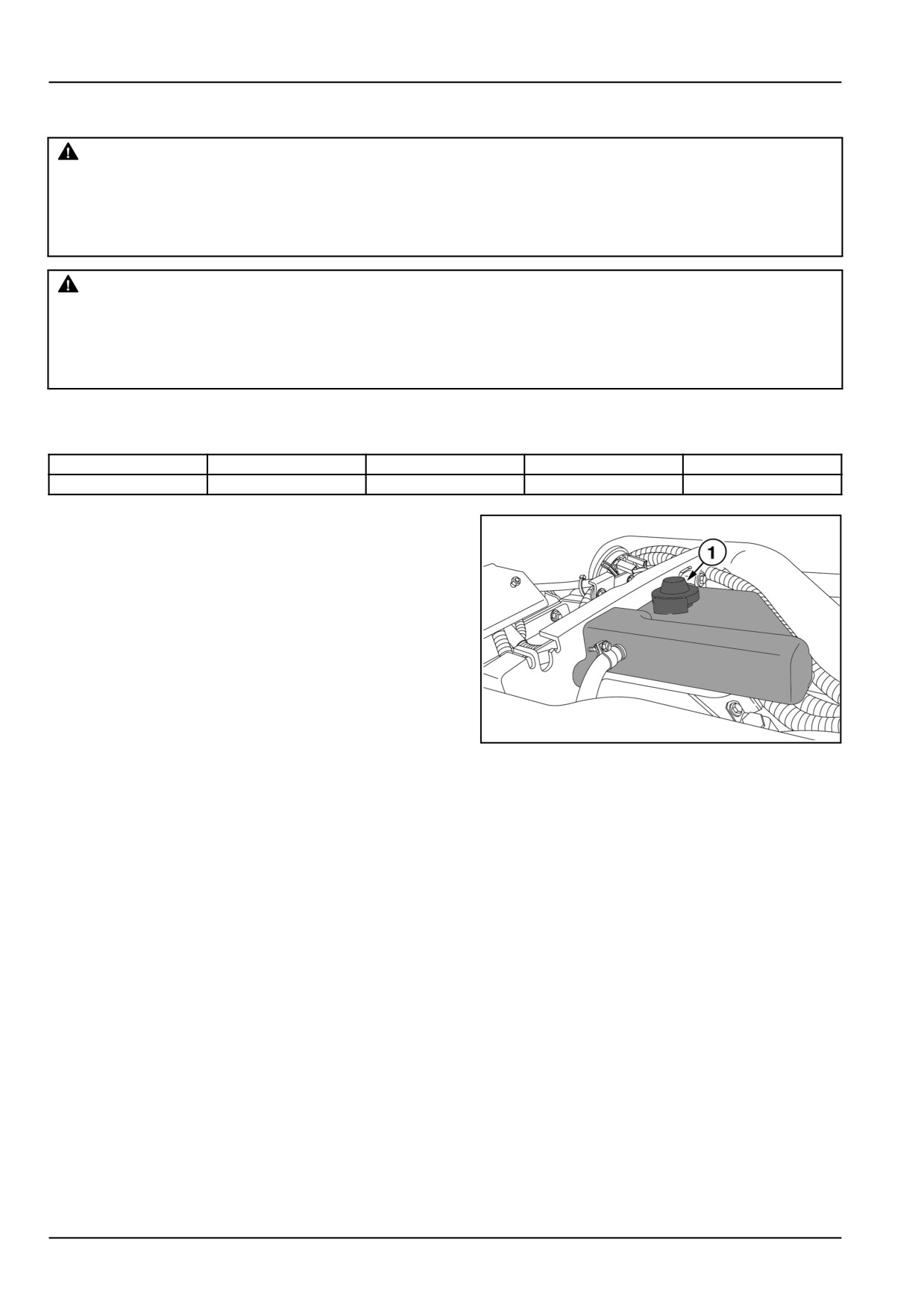
fitting (1). After filling, run the engine for a short period
to let the two fluids mix thoroughly.
DCSPFNEGB025S7A
1
7-42
7 - MAINTENANCE
Flushing the system (models without cab)
2.
WARNING
Hot surface possible!
Wait for all components to cool before per-
forming any operation.
Failure to comply could result in death or
serious injury.
W0251A
Flush at least every 1200 hours of work or every 2 years
and whenever switching from or to the anti-freeze mix-
ture.
Proceed as follows:
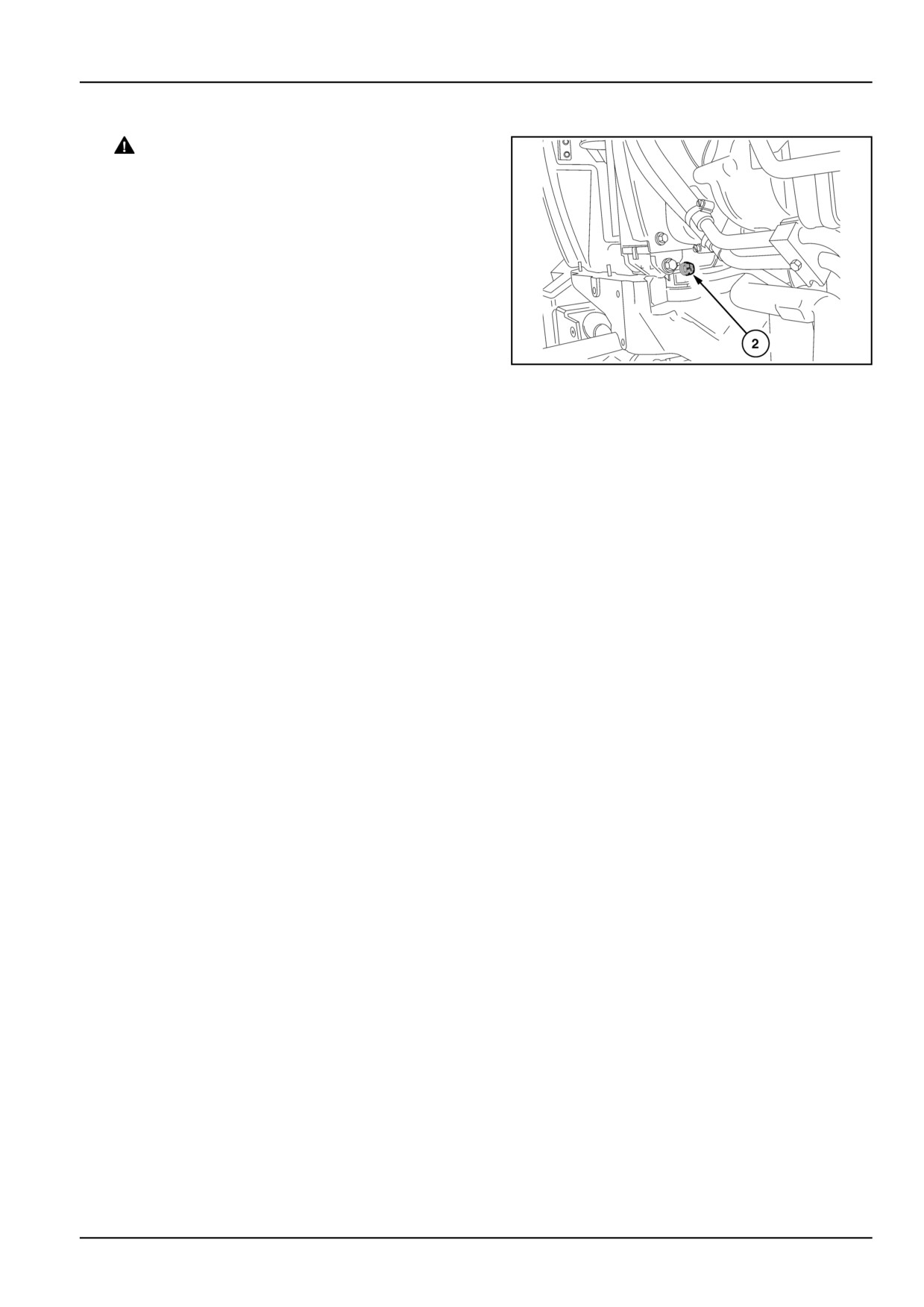
• Remove the expansion tank cap (1) fig. 1, then re-
DCSPVNEGB060S7A
2
move the radiator hose (1) fig.
2 and drain off the
fluid while the engine is cold;
• Put the radiator cap back on and fill the radiator with
a filtered solution of Solvay soda and water at a ratio
of 250 g (8.8 oz) of soda to every 10 l (2.2 UK gal)
2.70 US gal of water;
• Run the tractor for about an hour. Wait for the engine
to be cold, then drain the cleaning solution from the
radiator plug (2);
• then run pure water through it by pouring it into the
radiator and leaving it to drain through the radiator
plug (2) fig.
2;
• Replace the radiator plug, fill with water, run the en-
gine for a few minutes and drain the system;
• Leave the engine to cool, then fill the radiator with
a mixture of water and FLEETGUARD® COMPLEAT™
fluid, and close the radiator cap.
ATTENTION: The engine must be switched off when drain-
ing the water.
Thermostat
3. There is a thermostat in the cooling circuit to prevent
the water circulating in the radiator until the water
reaches a high enough temperature to allow the en-
gine to operate correctly (approx.
85 °C (185.0 °F). If
doubts arise concerning thermostat operation, remove
the part and have it checked by skilled personnel.
7-43
7 - MAINTENANCE
Flushing the system (models with cab)
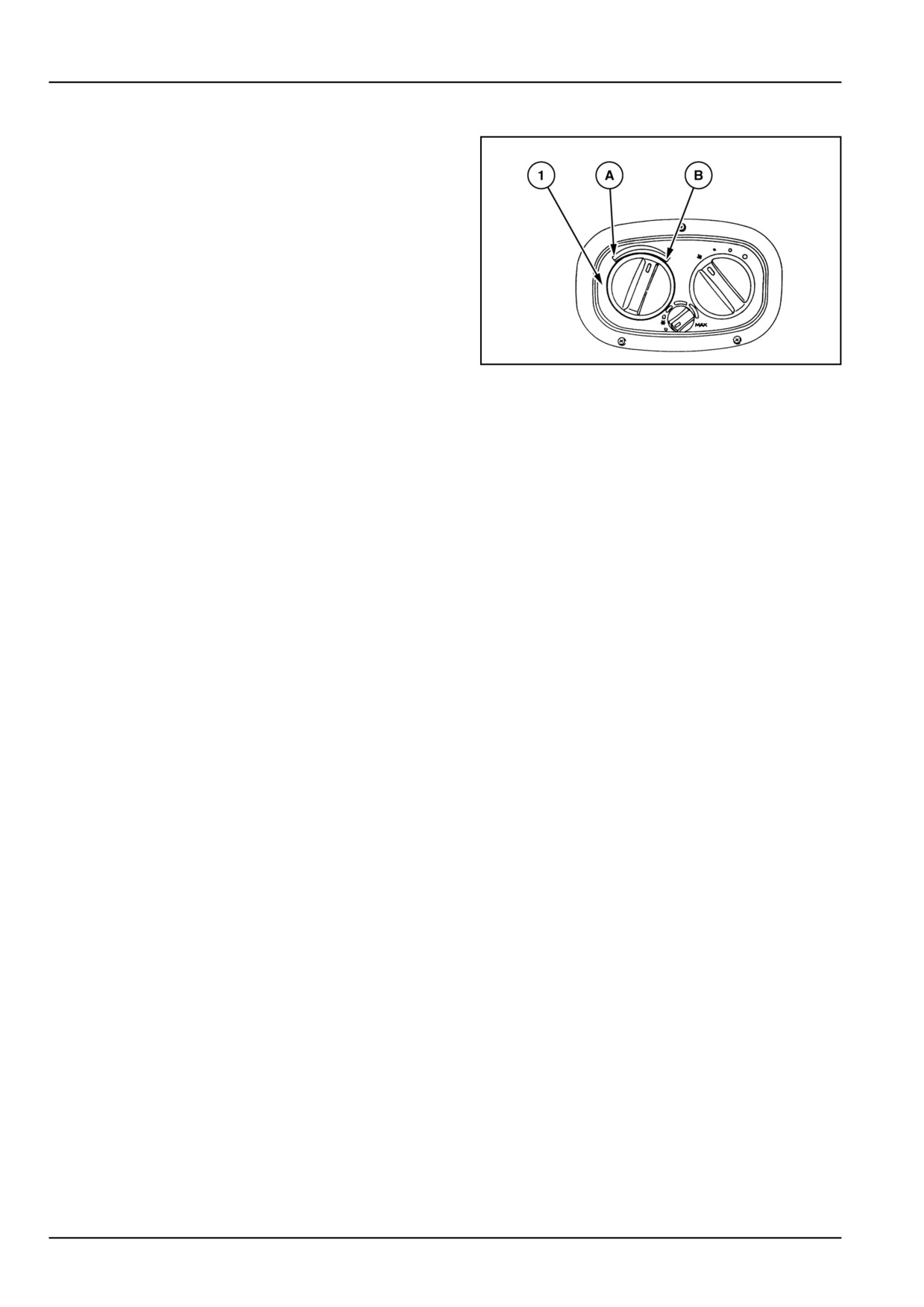
4. The heating system uses fluid from the engine cooling
system drawn off between the engine and the radiator.
Flush the system as described for models without a
cab, bearing in mind that the system can be completely
drained by turning temperature adjustment control (1),
fig.
3, to position (A).
Fill the engine cooling system and cab heating system
as follows:
• fill the radiator with a mixture of water and
FLEETGUARD® COMPLEAT™ antifreeze fluid and
screw on the radiator cap;
• close the heater cock (knob (1) in position (A)), start
the engine and leave it running at a medium speed
DCSPVNEGB061S7A
3
for approx.
5 - 10 min (this operation is necessary
to preheat the liquid in the engine cooling circuit;
• remove the upper radiator cap, open the heater cock
(knob (1) on position (B)) and allow the engine to run
at maximum speed for approximately five minutes;
• fill the radiator with the engine running at high revs
until it is completely full, and fit the cap.
7-44
7 - MAINTENANCE
EVERY 1800 HOURS
Fuel injectors - Check
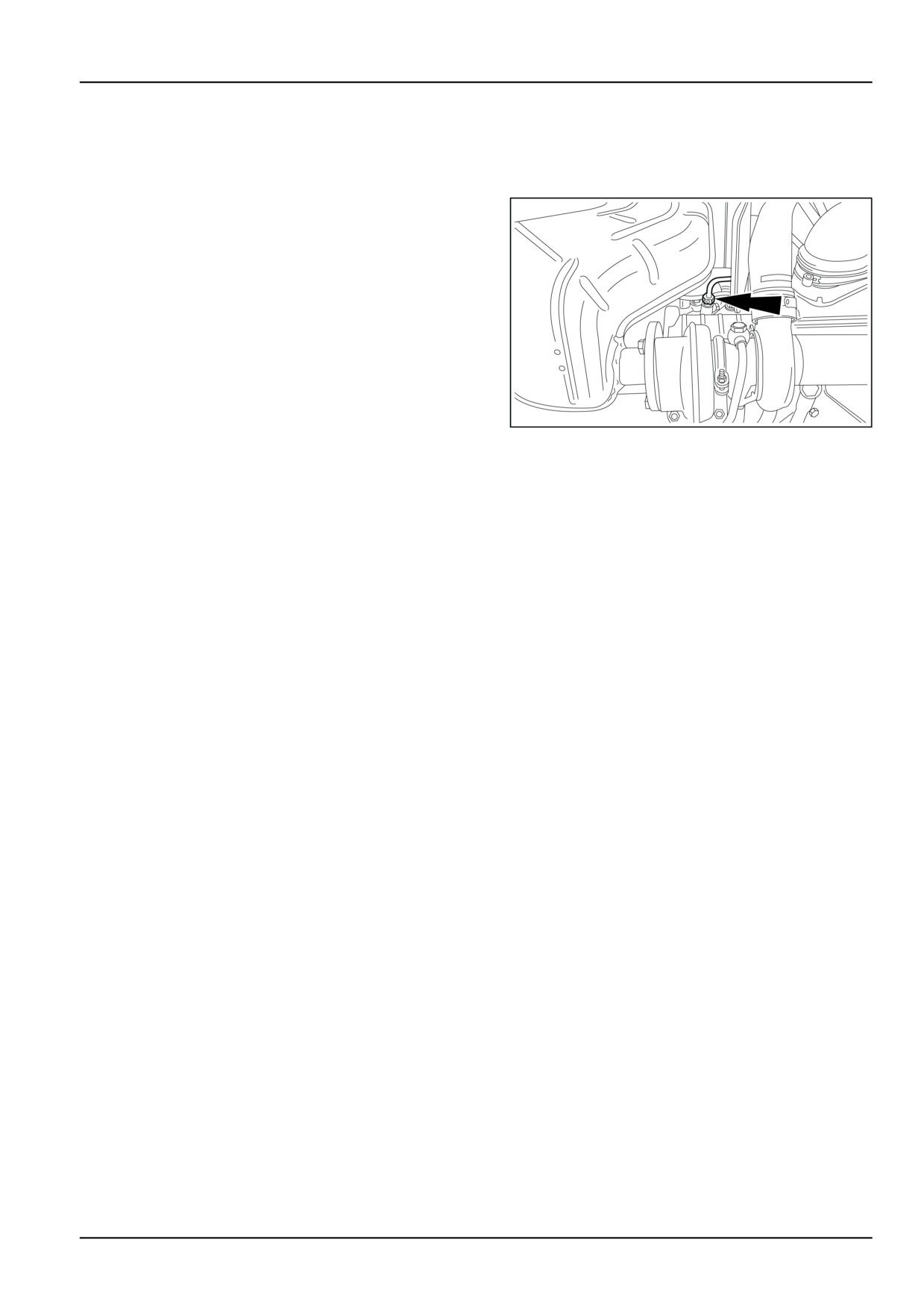
1. Have your local dealer check the pressure settings. To
remove from the engine, detach the lines and remove
the connectors.
NOTE: Before loosening or disconnecting any part of the
injection system, thoroughly clean the area in which you
are going to work.
Cover all injector lines and apertures to prevent any dirt
ingress.
MOIL13TR00688AA
1
7-45
7 - MAINTENANCE
ELECTRICAL SYSTEM
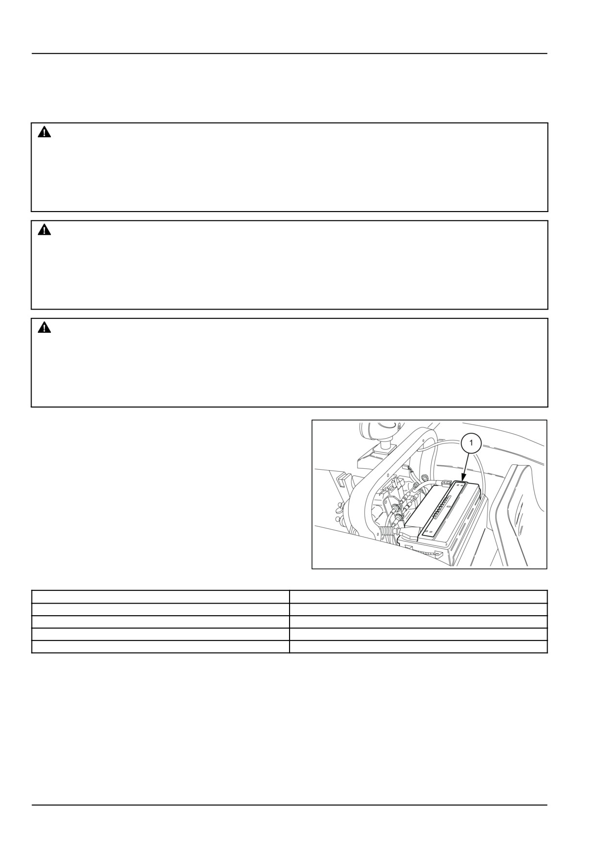
Battery
WARNING
Explosive gas!
Batteries emit explosive hydrogen gas and other fumes while charging. Ventilate the charging area.
Keep the battery away from sparks, open flames, and other ignition sources. Never charge a frozen
battery.
Failure to comply could result in death or serious injury.
W0005A
WARNING
Hazardous chemicals!
Battery electrolyte contains sulfuric acid. Contact with skin and eyes could result in severe irritation
and burns. Always wear splash-proof goggles and protective clothing (gloves and aprons). Wash
hands after handling.
Failure to comply could result in death or serious injury.
W0006A
WARNING
Battery gas can explode!
To prevent an explosion: 1. Always disconnect the negative (-) battery cable first. 2. Always connect
the negative (-) battery cable last. 3. Do not short circuit the battery posts with metal objects. 4. Do
not weld, grind, or smoke near a battery.
Failure to comply could result in death or serious injury.
W0011A
The tractors are fitted with maintenance-free batteries.
Keep the top part clean and dry. Check that the fluid
level reaches the top mark and never drops under the
bottom mark. If necessary lift covers (1) and add ONLY
distilled water.
Check the charge with a digital voltmeter in the follow-
ing way:
• Connect the voltmeter to the battery’s two terminals,
matching the terminal symbols (negative to negative
and positive to positive) and read the value from the
instrument
• Compare the figure with the values in the table below
to establish the charge in the battery.
MOIL13TR00689AA
1
Voltage
Charge level
12,66 V
100 %
12,45 V
75 %
12,30 V
50 %
12,00 V
25 %
If
the voltage is around 12,30 V, immediately recharge the battery with a current equivalent to 1/10 of the capacity
in Ah (a 50 Ah battery is to be charged to 5 A).
NOTICE: Always disconnect the cables before recharging the battery. The battery should be removed from its seat
and recharged at a safe distance from the tractor.
NOTE: Never use rapid “boost” battery chargers to recharge the battery.
Never fill up the battery with SULPHURIC ACID.
If the battery needs to be topped up frequently or tends to run down, have the electrical system checked by your local
Dealer.
7-46
7 - MAINTENANCE
NOTE: Batteries and storage batteries contain components that may be damaging to the environment if incorrectly
disposed of after use. The manufacturer strongly advises that all “dry” batteries, used in electrical or electronic sys-
tems, are returned to your local dealer. The dealer will dispose of (or recycle) the batteries correctly. This procedure
is requested by law in certain countries.
If an old battery needs to be replaced with a new one, proceed as follows:
• first disconnect the lead end marked with a negative sign (−), then the lead end with the positive sign (+);
• fit the new battery in the seat, without over- tightening the retaining screws;
• clean the lead ends and connect to the battery terminals, ensuring that the (−) negative terminal is connected last;
• fully tighten the lead ends on the terminals and smear them with petroleum jelly.
ADVICE ON STARTING THE ENGINE WITH A FLAT BATTERY OR NO BATTERY
To prevent damage to the alternator and its incorporated regulator follow the procedure below.
When the tractor battery is partially discharged, and an auxiliary battery has to be used to start the engine, connect
the battery to the tractor battery ensuring that the terminals match (positive to positive and negative to negative).
This rule must also be observed when recharging the battery externally.
If you have to start the engine with a totally flat battery or where the tractor does not have a battery remember that:
• it is not possible to jump start the tractor by towing, as the electro--magnetically operated injection pump cut--off
device will prevent the engine from starting;
• it is possible to start the tractor with an auxiliary battery after having first disconnected plug D+, terminal B+ and
the condenser but to no avail given that the engine will stop as soon as the external battery supply to the electro-
magnetic cut--off device is interrupted;
• avoid starting the engine with an auxiliary battery whilst plug D+, terminal B+ and the condenser are connected to
the alternator;
• however, it is necessary to connect a 12 V battery, capable of starting the tractor, and then to replace it with the
battery that is to be fitted on the tractor.
• Under normal conditions, the engine must never run without plug D+, terminal B+ and the condenser disconnected
from the alternator.
7-47

7 - MAINTENANCE
Fuses and relays
12−way fusebox and relays
1. On all models, the 12−way fuse box (1) is located on
the left−hand side of the central console, beneath the
steering wheel.
NOTE: When replacing a blown fuse, make sure that the
new fuse has the same amp value.
If electrical system relays need to be changed, check that
correct spare parts are used and that they are fitted in the
correct positions. The use of structurally or functionally
different relays - even if interchangeable - could seriously
compromise tractor control with dangerous results.
DCSPFNEGB075S4A
1
Six−way fusebox for cab circuit
2. Together with the main fuse box shown in fig. 1, tractors
with cabs are fitted with an additional 6 way fuse box
(1), located on the right−hand upright.
DCSPFNEGB076S4A
2
7-48
7 - MAINTENANCE
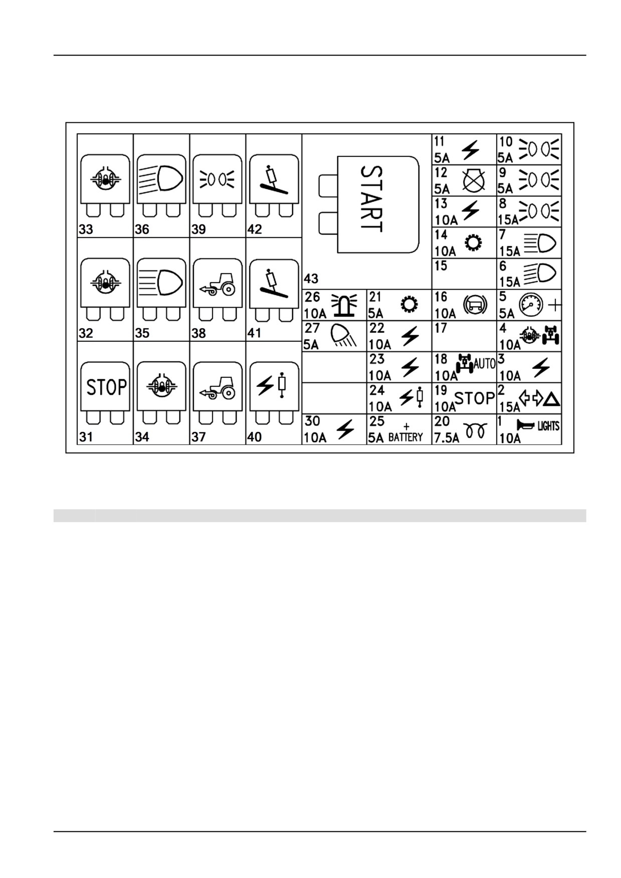
Fuses and relays location
Model without cab
MOIL13TR00724FA
1
NOTICE: Depending on your version some components described below might not be present.
Fuses
Ref.
Fuse Protected circuits
1
10 A Horn, driving beam flashing
2
15 A Turn and hazard lights.
3
10 A
8 A socket 8 A
4
10 A
Differential lock circuit, four-wheel drive circuit.
5
5 A
+ instrument cluster, electronic hydraulic lift switches and lamps
6
15 A Dipped beam headlight circuit.
7
15 A Full beam headlight circuit.
8
15 A Circuit of position lights or work lights for 7-pole socket.
9
5 A Front left-hand and rear right-hand position lights, instrument cluster light.
10
5 A Front right-hand and rear left-hand position lights, position lights indicator circuit.
11
5 A Engine starting safeties circuit.
12
5 A Engine shutdown electromagnet.
13
10 A Stabilizer lock circuit.
14
10 A Power Shuttle circuit
15
-
Not used
16
10 A Trailer brake and hydraulic adjustment circuit.
17
-
Position not used.
18
10 A Permanent 4WD circuit
19
10 A Brake lights circuit.
20
7.5 A Grid heater unit circuit.
21
5 A Power Shuttle lever
22
10 A Circuit for second and third distributor.
7-49
7 - MAINTENANCE
Ref.
Fuse Protected circuits
23
10 A Circuit for right-hand tie rod control.
24
10 A Ventral control valves
25
5 A Battery cut-out circuit
26
10 A Rotating beacon
27
5 A Rear work lights circuit.
28
-
Position not used.
29
-
Position not used.
30
10 A Power supply for keypad + key
Relay
Ref. Protected circuits
31
Brake lights (STOP)
32
Differential lock circuit
33
Differential lock circuit
34
Differential lock circuit
35
Full beam headlight circuit
36
Dipped beam headlight circuit
37
4WD circuit
38
Steering switch
39
Position lights circuit
40
Ventral control valves
41
Third hydraulic distributor
42
Second hydraulic distributor
43
Engine starting circuit maxi-relay
NOTE: If electrical system relays need to be changed, check that correct spare parts are used and that they are fitted
in the correct positions. The use of structurally or functionally different relays - even if interchangeable - may seriously
compromise tractor control with dangerous results.
7-50