New Holland Tractor T4.75F, T4.85F, T4.95F, T4.105F. OPERATOR’S MANUAL (2013) - page 3
3 - CONTROLS/INSTRUMENTS
Parking brake for hydraulic transmissions
Parking lock
NOTICE: On models with Power Shuttle and HI-LO when leaving the machine, besides applying the hand brake you
MUST engage the parking brake Parking lock.
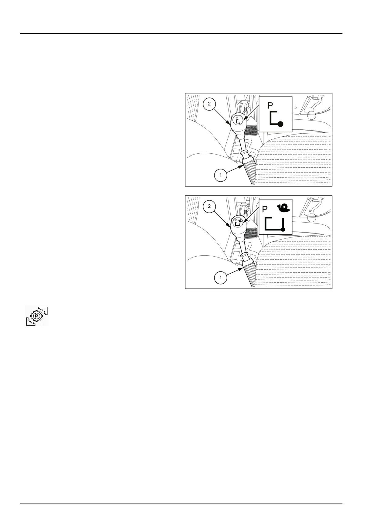
Figure 1 configuration with HI-LO, Power shuttle.
Figure 2 configuration with HI-LO, Power shuttle and
creeper unit.
Besides the hand brake (1) there is the parking brake con-
trolled by the lever (2). Its operation is as follows:
Engagement
With the tractor stationary, move the lever from the central
neutral position on the left, then forwards in the direction
(P) and subsequently to the right as shown on the plate
on the lever.
MOIL13TR00956AA
1
Disengagement
Before setting off with the tractor it is necessary to dis-
engage the brake. With the tractor stationary, move the
lever to the left, then backwards as shown on the plate on
the lever.
MOIL13TR00957AA
2
If you try and move the machine with the parking brake Parking lock engaged, the following warning
light will light up on the central display accompanied by an acoustic signal. Never try moving the
machine in this situation to avoid mechanical damage.
3-44
3 - CONTROLS/INSTRUMENTS
Transmission with gear reducer, electrohydraulic reversing mechanism
and HI-LO control
30 km/h (18.6 mph) - 40 km/h (24.9 mph) - 32
FWD +
16
REV
WARNING
Unexpected machine movement!
With the engine running and only the gear
lever in neutral, the machine can engage and
move suddenly if someone accidentally op-
erates this lever. Place all levers in neutral,
disengage the Power Take-Off (PTO), lower
any implements, set the handbrake and park-
ing brake before exiting the machine.
Failure to comply could result in death or se-
rious injury.
W1158B
The operation of the gear levers, range gear and electro-
MOIL13TR00838AA
1
hydraulic shuttle is the same as that previously described
on the "Transmission with gearbox and shuttle" pages for
the 16FWD+16REV version
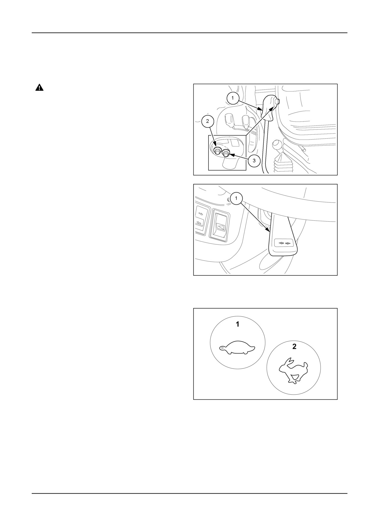
The gear lever (1) in fig.
1 is moreover equipped with
control buttons for the functions HI− LO (2) and (3), that
enable doubling the forward gear ratios, for a total of 32
available gears. It is possible to pass from position HI
(2) to position LO (3) by pressing the two buttons without
using the clutch pedals.
With the shuttle lever (1) fig.
2 in the reverse position
(backwards), position (HI) is automatically excluded, thus
reducing the number of available reverse gears to 16. To
MOIL13TR00505AA
2
reverse the direction of travel, lift and move the lever for-
wards or backwards. Drive direction can be changed with-
out pressing down the clutch pedal.
Operation
With the tractor moving it is possible to invert the drive
direction without stopping and without pressing down the
clutch pedal.
When driving forward in range HI and you move the shut-
tle lever (1) fig.
2 into reverse position, when the tractor
begins to reverse, the indicator (1) fig. 3 will illuminate to
signal the move into range LO.
When you move the shuttle lever (1) fig. 2 back into the
forward position, the indicator will illuminate (1) and the
indicator (2) fig.
3 will start flashing to indicate the auto-
matic passage from range LO to range HI set previously.
On completing the change, the indicator (1) will turn off,
MOIL13TR00523AA
3
while the indicator (2) will stay on to signal that range HI
is selected.
NOTE: The indicator (1) fig. 3 is present only in configu-
rations with an analogue instrument cluster.
3-45
3 - CONTROLS/INSTRUMENTS
SPEED AT MAXIMUM POWER
30 km/h (18.6 mph) transmission 32 FWD + 16 REV version
FORWARD SPEED
REAR TIRES
13.6 R 28
14.9 R 28
340/85 R 28
RANGE
GEAR
380/70 R 20
380/70 R 24
420/70 R 24
380/85 R 28
420/70 R 30
380/70 R 28
420/70 R 28
19.5L - 24
km/h
mph
km/h
mph
km/h
mph
km/h
mph
km/h
mph
km/h
mph
LO
0,53
0.33
0,45
0.28
0,47
0.29
0,49
0.31
0,51
0.32
0,53
0.33
1
HI
0,64
0.40
0,54
0.34
0,57
0.35
0,59
0.37
0,62
0.38
0,64
0.40
LO
0,80
0.49
0,68
0.42
0,71
0.44
0,74
0.46
0,76
0.47
0,79
0.49
2
HI
0,96
0.59
0,81
0.50
0,85
0.53
0,88
0.55
0,92
0.57
0,95
0.59
A
LO
1,17
0.73
0,99
0.62
1,04
0.64
1,08
0.67
1,12
0.7
1,17
0.72
3
HI
1,41
0.87
1,19
0.74
1,24
0.77
1,30
0.81
1,35
0.84
1,40
0.87
LO
1,73
1.08
1,47
0.91
1,54
0.95
1,60
0.99
1,66
1.03
1,73
1.07
4
HI
2,08
1.29
1,77
1.10
1,84
1.15
1,92
1.19
2,00
1.24
2,07
1.29
LO
2,25
1.40
1,91
1.18
1,99
1.24
2,07
1.29
2,15
1.34
2,24
1.39
1
HI
2,69
1.67
2,29
1.42
2,39
1.48
2,49
1.54
2,59
1.61
2,69
1.67
LO
3,35
2.08
2,84
1.77
2,96
1.84
3,09
1.92
3,21
2.0
3,34
2.07
2
HI
4,02
2.50
3,41
2.12
3,56
2.21
3,71
2.30
3,85
2.39
4,00
2.49
BL
LO
4,92
3.06
4,18
2.59
4,36
2.71
4,54
2.82
4,72
2.93
4,90
3.05
3
HI
5,90
3.67
5,01
3.11
5,23
3.25
5,45
3.38
5,67
3.52
5,88
3.66
LO
7,29
4.53
6,19
3.84
6,46
4.01
6,73
4.18
6,99
4.35
7,26
4.51
4
HI
8,75
5.43
7,42
4.61
7,75
4.81
8,07
5.01
8,39
5.22
8,72
5.42
LO
2,75
1.71
2,33
1.45
2,43
1.51
2,54
1.58
2,64
1.64
2,74
1.70
1
HI
3,30
2.05
2,80
1.74
2,92
1.82
3,04
1.89
3,62
2.25
3,29
2.04
LO
4,10
2.55
3,48
2.16
3,63
2.26
3,78
2.35
3,93
2.44
4,08
2.54
2
HI
4,92
3.05
4,17
2.59
4,36
2.71
4,54
2.82
4,72
2.93
4,90
3.04
BH
LO
6,02
3.74
5,11
3.18
5,34
3.32
5,56
3.45
5,78
3.59
6,00
3.73
3
HI
7,23
4.49
6,14
3.81
6,40
3.98
6,67
4.14
6,94
4.31
7,20
4.48
LO
8,92
5.54
7,57
4.71
7,90
4.91
9,88
6.14
8,56
5.32
8,89
5.52
4
HI
10,71
6.65
9,09
5.65
9,48
5.89
9,88
6.14
10,27
6.38
10,67
6.63
LO
7,93
4.93
6,74
4.19
7,03
4.37
7,32
4.55
7,61
4.73
7,91
4.91
1
HI
9,52
5.92
8,08
5.02
8,43
5.24
8,79
5.46
9,14
5.68
9,49
5.90
LO
11,83
7.35
10,05
6.24
10,48
6.51
10,91
6.78
11,35
7.05
11,79
7.32
2
HI
14,19
8.82
12,05
7.49
12,57
7.81
13,10
8.14
13,62
8.46
14,15
8.79
C
LO
17,39
10.8
14,76
9.17
15,40
9.57
16,04
9.97
16,69
10.37
17,33
10.77
3
HI
20,86
12.96
17,71
11.01
18,48
11.48
19,25
11.96
20,02
12.44
20,79
12.92
LO
25,76
16.01
21,87
13.59
22,82
14.18
23,77
14.77
24,72
15.36
25,67
15.95
4
HI
30,91
19.21
26,24
16.31
27,38
17.01
28,52
17.72
29,66
18.43
30,80
19.14
NOTE: With the creeper switched off, the forward and reverse gear ratios are the same as indicated for the
16 FWD
+ 16 REV transmissions.
3-46

3 - CONTROLS/INSTRUMENTS
SPEED AT MAXIMUM POWER
40 km/h (24.9 mph) transmission 32 FWD + 16 REV version
FORWARD SPEED
REAR TIRES
13.6 R 28
14.9 R 28
340/85 R 28
RANGE
GEAR
380/70 R 20
380/70 R 24
420/70 R 24
380/85 R 28
420/70 R 30
380/70 R 28
420/70 R 28
19.5L - 24
km/h
mph
km/h
mph
km/h
mph
km/h
mph
km/h
mph
km/h
mph
LO
0,69
0.43
0,59
0.36
0,61
0.38
0,64
0.40
0,66
0.41
0,69
0.43
1
HI
0,83
0.52
0,70
0.44
0,73
0.46
0,76
0.47
0,79
0.49
0,82
0.51
LO
1,03
0.64
0,87
0.54
0,91
0.57
0,95
0.59
0,99
0.61
1,02
0.64
2
HI
1,24
0.77
1,05
0.65
1,09
0.68
1,14
0.71
1,18
0.74
1,23
0.76
A
LO
1,52
0.94
1,28
0.80
1,34
0.83
1,39
0.87
1,45
0.90
1,51
0.94
3
HI
1,82
1.13
1,54
0.96
1,61
1.00
1,67
1.04
1,74
1.08
1,81
1.12
LO
2,25
1.40
1,90
1.18
1,98
1.23
2,06
1.28
2,15
1.33
2,23
1.39
4
HI
2,70
1.68
2,28
1.42
2,38
1.48
2,48
1.54
2,58
1.60
2,68
1.66
LO
2,92
1.81
2,46
1.53
2,57
1.59
2,67
1.66
2,78
1.73
2,89
1.79
1
HI
3,50
2.17
2,95
1.83
3,08
1.91
3,21
1.99
3,34
2.07
3,46
2.15
LO
4,34
2.7
3,67
2.28
3,83
2.38
3,98
2.48
4,14
2.57
4,30
2.67
2
HI
5,21
3.24
4,40
2.73
4,59
2.85
4,78
2.97
4,97
3.09
5,16
3.21
BL
LO
6,39
3.97
5,39
3.35
5,62
3.49
5,59
3.47
6,09
3.78
6,33
3.93
3
HI
7,66
4.76
6,47
4.02
6,75
4.19
7,03
4.37
7,31
4.54
7,59
4.72
LO
9,46
5.88
7,98
4.96
8,33
5.18
8,68
5.39
9,02
5.61
9,37
5.82
4
HI
11,35
7.05
9,58
5.95
10,00
6.21
10,41
6.47
10,83
6.73
11,24
6.99
LO
3,57
2.22
3,01
1.87
3,14
1.95
3,27
2.03
3,40
2.11
3,53
2.20
1
HI
4,28
2.66
3,61
2.24
3,77
2.34
3,93
2.44
4,08
2.54
4,24
2.63
LO
5,32
3.30
4,49
2.79
4,68
2.91
4,88
3.03
5,07
3.15
5,27
3.27
2
HI
6,38
3.97
5,38
3.35
5,62
3.49
5,85
3.64
6,09
3.78
6,32
3.93
BH
LO
7,82
4.86
6,60
4.1
6,88
4.28
7,17
4.45
7,46
4.63
7,74
4.81
3
HI
9,38
5.83
7,92
4.92
8,26
5.13
8,60
5.35
8,95
5.56
9,29
5.77
LO
11,58
7.20
9,77
6.07
10,20
6.34
10,62
6.60
11,05
6.86
11,47
7.13
4
HI
13,90
8.64
11,73
7.29
12,75
7.92
12,75
7.92
13,26
8.24
13,77
8.55
LO
10,30
6.40
8,69
5.40
9,07
5.63
9,45
5.87
9,82
6.10
10,20
6.34
1
HI
12,36
7.68
10,43
6.48
10,88
6.76
11,34
7.04
11,79
7.33
2,24
1.39
LO
15,35
9.54
12,95
8.05
13,52
8.40
14,08
8.75
14,64
9.10
15,21
9.45
2
HI
18,42
11.45
15,55
9.66
16,22
10.08
16,90
10.5
17,57
10.92
18,25
11.34
C
LO
22,57
14.02
19,04
11.83
19,87
12.35
20,70
12.86
21,53
13.38
22,35
13.89
3
HI
27,08
16.83
22,85
14.2
23,85
14.82
24,84
15.43
25,83
16.05
26,83
16.67
LO
33,44
20.78
28,21
17.53
29,44
18.29
30,66
19.05
31,89
19.82
33,12
20.58
4
HI
40,12
24.93
33,85
21.04
35,33
21.95
36,80
22.87
38,27
23.78
39,74
24.70
NOTE: With the creeper switched off, the forward and reverse gear ratios are the same as indicated for the 16 FWD
+ 16 REV transmissions.
3-47
3 - CONTROLS/INSTRUMENTS
Transmission with gear reducer, electrohydraulic reversing mechanism,
HI-LO control and electrohydraulic clutch
30 km/h (18.6 mph) - 40 km/h (24.9 mph) - 32 FWD + 16 REV
WARNING
Unexpected machine movement!
With the engine running and only the gear lever in neutral, the machine can engage and move suddenly
if someone accidentally operates this lever. Place all levers in neutral, disengage the Power Take-Off
(PTO), lower any implements, set the handbrake and parking brake before exiting the machine.
Failure to comply could result in death or serious injury.
W1158B
The operation of the gear levers, range gear and electro-
hydraulic shuttle is the same as that previously described
on the "Transmission with gearbox and shuttle" pages for
the 16FWD+16REV version
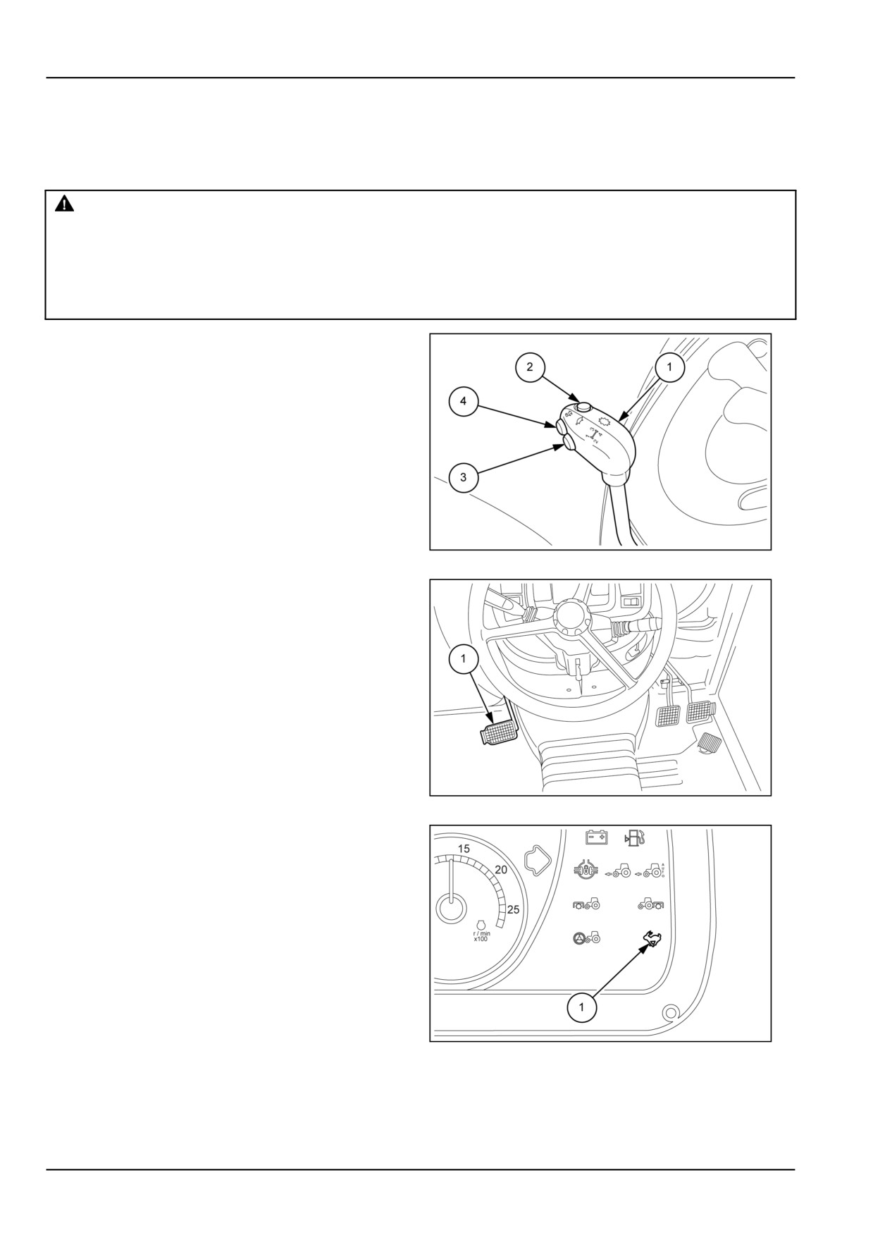
There are three buttons on the gear lever (1).
Buttons (3) and (4) govern the dual command (2-speed
power shift) functions. By using the two buttons you can
obtain two speeds in the same gear ratio without having
to use the clutch pedal (1) fig. 2.
MOIL13TR00524AA
1
The button (2) fig. 1 governs the electro-hydraulic clutch.
By pressing the button it is possible to pass from one gear
to another without using the clutch pedal (1).
NOTE: To start from a standstill it is necessary to press
the clutch pedal. When the tractor is in motion, use the
button (2) fig. 2 to pass from one gear to another.
You can then pass from position HI to position LO or vice
versa, without operating the clutch pedal as engagement
is aided by hydraulic clutches governed electrically by
three push-buttons (2), (3) and (4). To select the tractor's
direction of travel, use the shuttle lever.
MOIL13TR00525AA
2
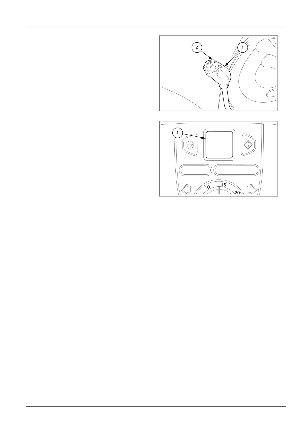
Dual Command (2 Speed Power Shift) Push-
Buttons
To select the LO or HI position, use the buttons (3) and
(4) fig.
1.
(3) Range selection button LO. No indicator lights up
when the LO range is engaged.
(4) Range selection button HI. With the HI range engaged,
the indicator (1) (with the hare symbol) is illuminated.
NOTE: To start the engine, set the shuttle lever on the
central neutral position. In addition, it is recommended to
MOIL13TR00526AA
3
press the clutch pedal fully down.
3-48
3 - CONTROLS/INSTRUMENTS
Electro-hydraulic clutch
The electro-hydraulic operation of the clutch allows the
operator to control the movement of the tractor without
using the clutch pedal by simply moving the gear lever
from one gear to another, whether forwards or in reverse,
without using the clutch pedal (1) fig. 2.
After selecting the required range, move the shuttle lever
into the forward or reverse gear position, press the push
button (2), without pressing the clutch pedal move the
gear lever (1) onto the required gear and release the but-
ton to set the tractor in motion.
MOIL13TR00527AA
4
NOTE: The function is disabled when you keep button (2)
fig.
4 pressed for longer than 10 seconds or if you get
up out of the driving seat with the tractor in motion. Can-
celling the function is highlighted by an audible warning,
followed by a message on the performance monitor show-
ing CP (1).
To reactivate this function you can move the shuttle
control lever into neutral or momentarily press the clutch
pedal.
MOIL13TR00528AA
5
Dual Command (2 Speed Power Shift) dis-
abling indicator
The transmission can be disabled in one of three ways:
1. Initial test
2. Temporary disabling of the transmission
3. Permanent disabling of the transmission.
Initial test
During the tractor start-up phase, the control unit can de-
tect conditions that block operation, for example:
- excessive oil viscosity at low temperatures;
- problems of a hydraulic or mechanical nature.
If the oil temperature is low because of the weather condi-
tions, the test performed automatically by the control unit
can take several seconds. In this case, wait for the auto-
matic test to end and leave the engine idling until the oil
reaches its normal operating temperature.
3-49
3 - CONTROLS/INSTRUMENTS
Transmission disabled
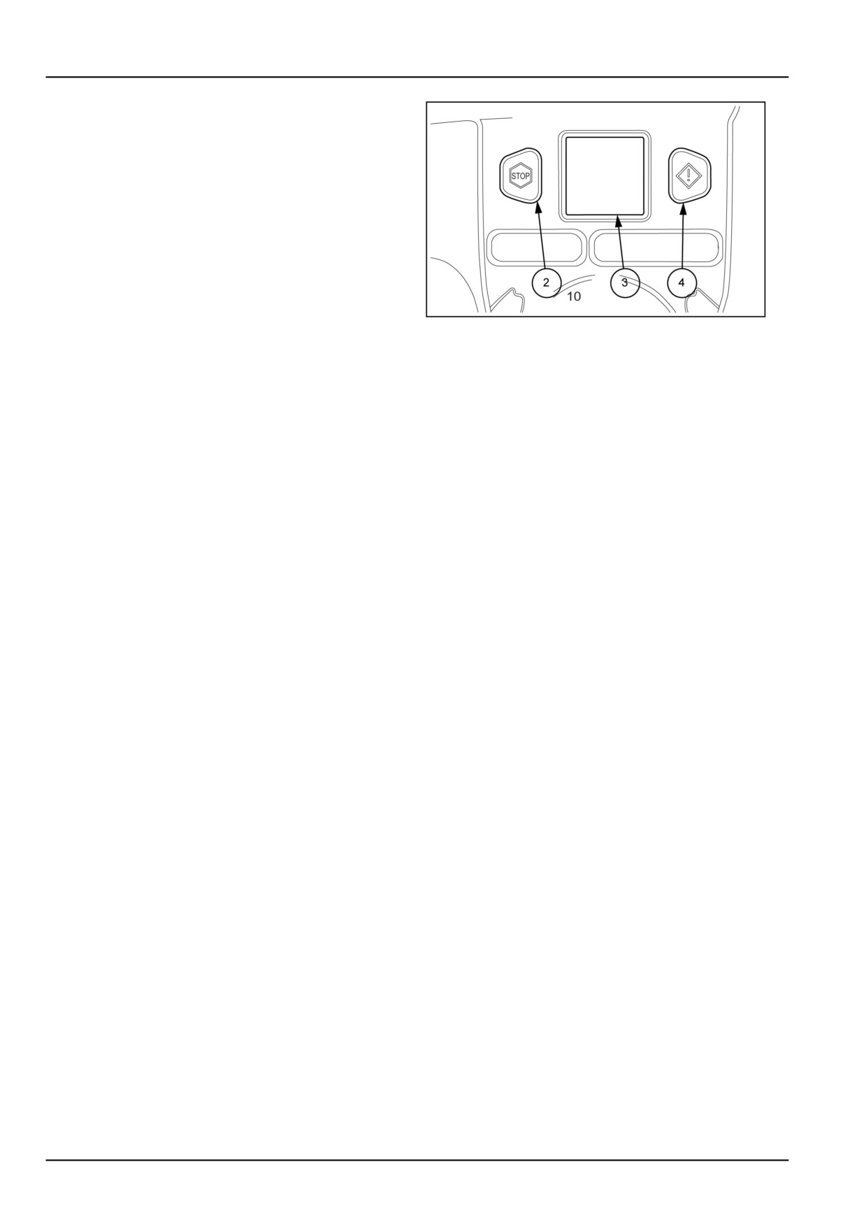
If the control unit detects an improper sequence of oper-
ator controls, or problems in the system, it disables the
transmission.
If the red “ Stop” warning light (2) comes on, switch off
the tractor immediately and look for the cause. A warning
symbol will appear on the display (3) confirming the loca-
tion of the fault.
Amber indicator (4) − This indicator light comes on and
the display shows a warning symbol (3). The light blinks
for 4 seconds, after which the symbol on the display dis-
MOIL13TR00529AA
6
appears and the indicator light stays on steady. To display
the trouble it is necessary to enter the menu, stop the trac-
tor and search for the cause.
3-50

3 - CONTROLS/INSTRUMENTS
SPEED AT MAXIMUM POWER
30 km/h (18.6 mph) transmission 32 FWD + 16 REV version
FORWARD SPEED
REAR TIRES
13.6 R 28
14.9 R 28
340/85 R 28
RANGE
GEAR
380/70 R 20
380/70 R 24
420/70 R 24
380/85 R 28
420/70 R 30
380/70 R 28
420/70 R 28
19.5L - 24
km/h
mph
km/h
mph
km/h
mph
km/h
mph
km/h
mph
km/h
mph
LO
0,53
0.33
0,45
0.28
0,47
0.29
0,49
0.31
0,51
0.32
0,53
0.33
1
HI
0,64
0.40
0,54
0.34
0,57
0.35
0,59
0.37
0,62
0.38
0,64
0.40
LO
0,80
0.49
0,68
0.42
0,71
0.44
0,74
0.46
0,76
0.47
0,79
0.49
2
HI
0,96
0.59
0,81
0.50
0,85
0.53
0,88
0.55
0,92
0.57
0,95
0.59
A
LO
1,17
0.73
0,99
0.62
1,04
0.64
1,08
0.67
1,12
0.7
1,17
0.72
3
HI
1,41
0.87
1,19
0.74
1,24
0.77
1,30
0.81
1,35
0.84
1,40
0.87
LO
1,73
1.08
1,47
0.91
1,54
0.95
1,60
0.99
1,66
1.03
1,73
1.07
4
HI
2,08
1.29
1,77
1.10
1,84
1.15
1,92
1.19
2,00
1.24
2,07
1.29
LO
2,25
1.40
1,91
1.18
1,99
1.24
2,07
1.29
2,15
1.34
2,24
1.39
1
HI
2,69
1.67
2,29
1.42
2,39
1.48
2,49
1.54
2,59
1.61
2,69
1.67
LO
3,35
2.08
2,84
1.77
2,96
1.84
3,09
1.92
3,21
2.0
3,34
2.07
2
HI
4,02
2.50
3,41
2.12
3,56
2.21
3,71
2.30
3,85
2.39
4,00
2.49
BL
LO
4,92
3.06
4,18
2.59
4,36
2.71
4,54
2.82
4,72
2.93
4,90
3.05
3
HI
5,90
3.67
5,01
3.11
5,23
3.25
5,45
3.38
5,67
3.52
5,88
3.66
LO
7,29
4.53
6,19
3.84
6,46
4.01
6,73
4.18
6,99
4.35
7,26
4.51
4
HI
8,75
5.43
7,42
4.61
7,75
4.81
8,07
5.01
8,39
5.22
8,72
5.42
LO
2,75
1.71
2,33
1.45
2,43
1.51
2,54
1.58
2,64
1.64
2,74
1.70
1
HI
3,30
2.05
2,80
1.74
2,92
1.82
3,04
1.89
3,62
2.25
3,29
2.04
LO
4,10
2.55
3,48
2.16
3,63
2.26
3,78
2.35
3,93
2.44
4,08
2.54
2
HI
4,92
3.05
4,17
2.59
4,36
2.71
4,54
2.82
4,72
2.93
4,90
3.04
BH
LO
6,02
3.74
5,11
3.18
5,34
3.32
5,56
3.45
5,78
3.59
6,00
3.73
3
HI
7,23
4.49
6,14
3.81
6,40
3.98
6,67
4.14
6,94
4.31
7,20
4.48
LO
8,92
5.54
7,57
4.71
7,90
4.91
9,88
6.14
8,56
5.32
8,89
5.52
4
HI
10,71
6.65
9,09
5.65
9,48
5.89
9,88
6.14
10,27
6.38
10,67
6.63
LO
7,93
4.93
6,74
4.19
7,03
4.37
7,32
4.55
7,61
4.73
7,91
4.91
1
HI
9,52
5.92
8,08
5.02
8,43
5.24
8,79
5.46
9,14
5.68
9,49
5.90
LO
11,83
7.35
10,05
6.24
10,48
6.51
10,91
6.78
11,35
7.05
11,79
7.32
2
HI
14,19
8.82
12,05
7.49
12,57
7.81
13,10
8.14
13,62
8.46
14,15
8.79
C
LO
17,39
10.8
14,76
9.17
15,40
9.57
16,04
9.97
16,69
10.37
17,33
10.77
3
HI
20,86
12.96
17,71
11.01
18,48
11.48
19,25
11.96
20,02
12.44
20,79
12.92
LO
25,76
16.01
21,87
13.59
22,82
14.18
23,77
14.77
24,72
15.36
25,67
15.95
4
HI
30,91
19.21
26,24
16.31
27,38
17.01
28,52
17.72
29,66
18.43
30,80
19.14
NOTE: With the creeper switched off, the forward and reverse gear ratios are the same as indicated for the 16 FWD
+ 16 REV transmissions.
3-51
3 - CONTROLS/INSTRUMENTS
SPEED AT MAXIMUM POWER
40 km/h (24.9 mph) transmission 32 FWD + 16 REV version
FORWARD SPEED
REAR TIRES
13.6 R 28
14.9 R 28
340/85 R 28
RANGE
GEAR
380/70 R 20
380/70 R 24
420/70 R 24
380/85 R 28
420/70 R 30
380/70 R 28
420/70 R 28
19.5L - 24
km/h
mph
km/h
mph
km/h
mph
km/h
mph
km/h
mph
km/h
mph
LO
0,69
0.43
0,59
0.36
0,61
0.38
0,64
0.40
0,66
0.41
0,69
0.43
1
HI
0,83
0.52
0,70
0.44
0,73
0.46
0,76
0.47
0,79
0.49
0,82
0.51
LO
1,03
0.64
0,87
0.54
0,91
0.57
0,95
0.59
0,99
0.61
1,02
0.64
2
HI
1,24
0.77
1,05
0.65
1,09
0.68
1,14
0.71
1,18
0.74
1,23
0.76
A
LO
1,52
0.94
1,28
0.80
1,34
0.83
1,39
0.87
1,45
0.90
1,51
0.94
3
HI
1,82
1.13
1,54
0.96
1,61
1.00
1,67
1.04
1,74
1.08
1,81
1.12
LO
2,25
1.40
1,90
1.18
1,98
1.23
2,06
1.28
2,15
1.33
2,23
1.39
4
HI
2,70
1.68
2,28
1.42
2,38
1.48
2,48
1.54
2,58
1.60
2,68
1.66
LO
2,92
1.81
2,46
1.53
2,57
1.59
2,67
1.66
2,78
1.73
2,89
1.79
1
HI
3,50
2.17
2,95
1.83
3,08
1.91
3,21
1.99
3,34
2.07
3,46
2.15
LO
4,34
2.7
3,67
2.28
3,83
2.38
3,98
2.48
4,14
2.57
4,30
2.67
2
HI
5,21
3.24
4,40
2.73
4,59
2.85
4,78
2.97
4,97
3.09
5,16
3.21
BL
LO
6,39
3.97
5,39
3.35
5,62
3.49
5,59
3.47
6,09
3.78
6,33
3.93
3
HI
7,66
4.76
6,47
4.02
6,75
4.19
7,03
4.37
7,31
4.54
7,59
4.72
LO
9,46
5.88
7,98
4.96
8,33
5.18
8,68
5.39
9,02
5.61
9,37
5.82
4
HI
11,35
7.05
9,58
5.95
10,00
6.21
10,41
6.47
10,83
6.73
11,24
6.99
LO
3,57
2.22
3,01
1.87
3,14
1.95
3,27
2.03
3,40
2.11
3,53
2.20
1
HI
4,28
2.66
3,61
2.24
3,77
2.34
3,93
2.44
4,08
2.54
4,24
2.63
LO
5,32
3.30
4,49
2.79
4,68
2.91
4,88
3.03
5,07
3.15
5,27
3.27
2
HI
6,38
3.97
5,38
3.35
5,62
3.49
5,85
3.64
6,09
3.78
6,32
3.93
BH
LO
7,82
4.86
6,60
4.1
6,88
4.28
7,17
4.45
7,46
4.63
7,74
4.81
3
HI
9,38
5.83
7,92
4.92
8,26
5.13
8,60
5.35
8,95
5.56
9,29
5.77
LO
11,58
7.20
9,77
6.07
10,20
6.34
10,62
6.60
11,05
6.86
11,47
7.13
4
HI
13,90
8.64
11,73
7.29
12,75
7.92
12,75
7.92
13,26
8.24
13,77
8.55
LO
10,30
6.40
8,69
5.40
9,07
5.63
9,45
5.87
9,82
6.10
10,20
6.34
1
HI
12,36
7.68
10,43
6.48
10,88
6.76
11,34
7.04
11,79
7.33
2,24
1.39
LO
15,35
9.54
12,95
8.05
13,52
8.40
14,08
8.75
14,64
9.10
15,21
9.45
2
HI
18,42
11.45
15,55
9.66
16,22
10.08
16,90
10.5
17,57
10.92
18,25
11.34
C
LO
22,57
14.02
19,04
11.83
19,87
12.35
20,70
12.86
21,53
13.38
22,35
13.89
3
HI
27,08
16.83
22,85
14.2
23,85
14.82
24,84
15.43
25,83
16.05
26,83
16.67
LO
33,44
20.78
28,21
17.53
29,44
18.29
30,66
19.05
31,89
19.82
33,12
20.58
4
HI
40,12
24.93
33,85
21.04
35,33
21.95
36,80
22.87
38,27
23.78
39,74
24.70
NOTE: With the creeper switched off, the forward and reverse gear ratios are the same as indicated for the
16 FWD
+ 16 REV transmissions.
3-52
4 - OPERATING INSTRUCTIONS
4 - OPERATING INSTRUCTIONS###_4_###
COMMISSIONING THE UNIT
Basic operating safety rules
WARNING
Inhalation/asphyxiation hazard!
Make sure there is proper ventilation before starting the engine.
Failure to comply could result in death or serious injury.
W0091A
WARNING
Unexpected machine movement!
Before starting the engine, move all operating controls to neutral or park lock position. This prevents
accidental movement of the machine or start up of power-driven equipment.
Failure to comply could result in death or serious injury.
W0302A
WARNING
Hazard to bystanders!
ALWAYS make sure the work area is clear of bystanders and domestic animals before starting this
procedure. Know the full area of movement of the machine. Do not permit anyone to enter the area
of movement during this procedure.
Failure to comply could result in death or serious injury.
W0245A
WARNING
IMPROPER OPERATION OF THIS MACHINE CAN CAUSE DEATH OR SERIOUS INJURY.
MAKE SURE THAT EVERY OPERATOR:
-is instructed in the safe and proper use of this machine.
-reads and understands the operator's manual for this machine.
-reads and understands ALL safety signs on the machine.
Failure to comply could result in death or serious injury.
W0188A
WARNING
Avoid injury!
Carefully read and observe all the precautionary advice contained in this manual.
Failure to comply could result in death or serious injury.
W0044A
WARNING
Misuse hazard!
Before starting the engine, make sure you are fully aware of the location and the function of each
control.
Failure to comply could result in death or serious injury.
W0226A
The purpose of this Operator's Manual is to provide the user with information, documents and practical instructions.
Read the Operator's Manual carefully before using the tractor. This is particularly important if the tractor is to be used
correctly as it contains all the information required on the layout and use of the tractor controls.
Even if you already have experience in using other makes of tractor, this manual must be studied carefully and thor-
oughly.
4-1
4 - OPERATING INSTRUCTIONS
Do not start the engine or attempt to drive or operate the tractor until you are fully accustomed with all controls. It is
too late to learn once the tractor is moving.
If you have any doubts about any functional aspect of the tractor, contact you NEW HOLLAND dealer.
The dealer can provide skilled personnel, original spare parts and the necessary equipment to carry out your service
requirements.
The manufacturer is engaged in a continuous process of product development and improvement and therefore re-
serves the right to change the specifications, components and prices of the product itself at any time, without prior
notice.
All the data provided in this Manual is subject to product modifications. Weights and measures are to be considered
approximate figures and the illustrations do not necessarily show tractors with standard fittings.
For precise information on specific tractor models and versions, please contact your authorised dealer.
Particular attention needs to be paid to the tractor’s running−in period, to obtain the best operating reliability and
service life for which it is designed and built.
With regard to the reliability and service life of your tractor, study Section 7 carefully. Section 7 contains details of all
the lubrication and general maintenance operations to be carried out on the tractor.
Tractor specifications are listed in Section 9.
In this manual, any references to the left and right sides of the tractor are intended as seen from the driver’s seat
facing forward.
4-2
4 - OPERATING INSTRUCTIONS
STARTING THE UNIT
Starting the engine
Your tractor will guarantee reliable service if care is taken
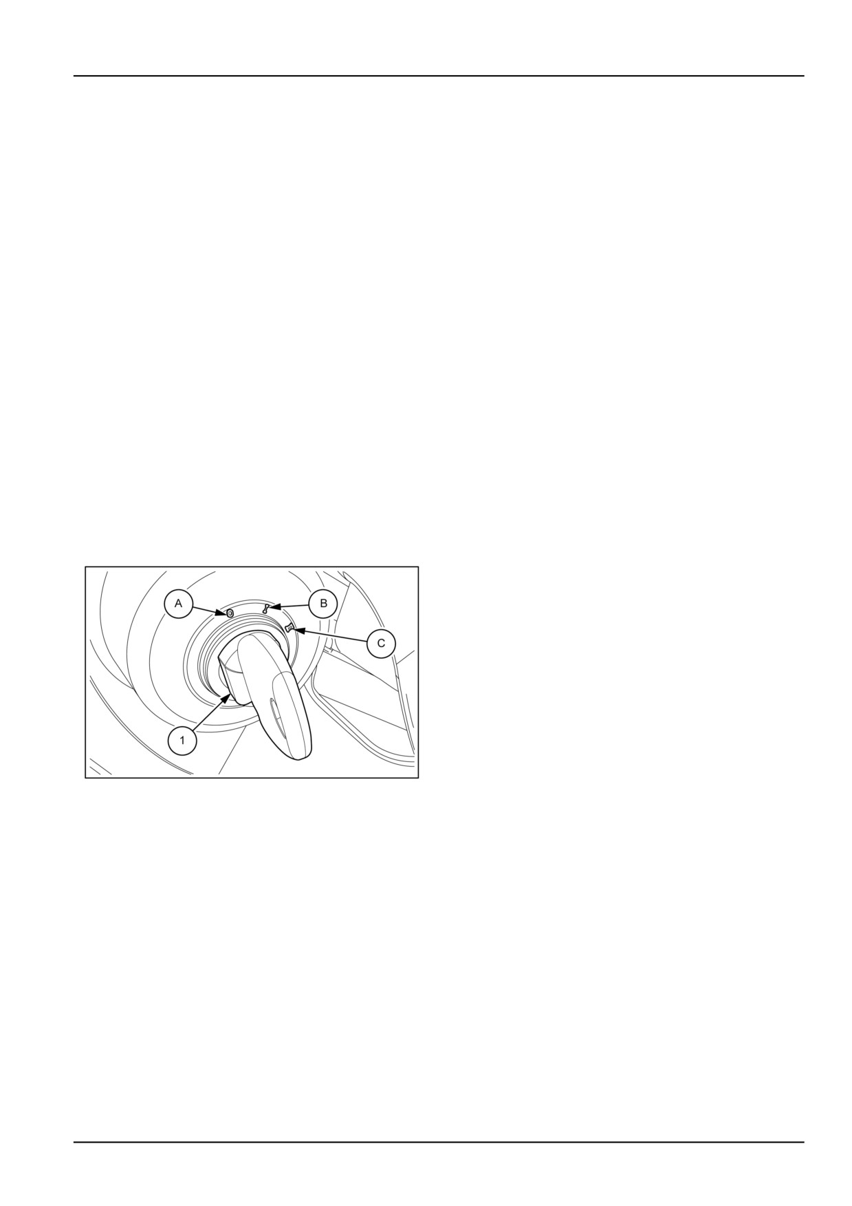
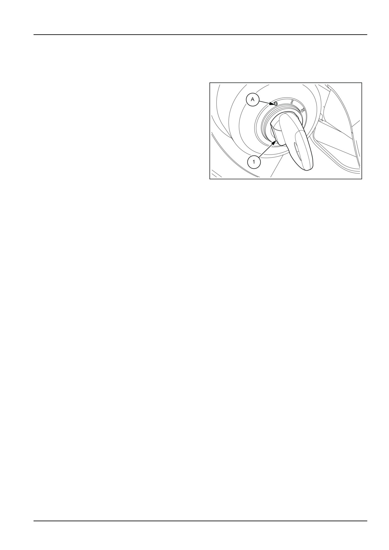
5. Turn the starter key to position (C) figure 1. Release
during the running−in period (first 50 hours of work), and
the key as soon as the engine starts.
if the maintenance recommendations in section 7 (Main-
NOTICE: If one of the warning lights illuminates to signal
tenance) are carefully followed.
a fault, check and repair the faulty part. If the warning light
continues to signal a fault, have the machine checked by
Before operating the tractor, ensure that you are thor-
your dealer.
oughly familiar with the location and operation of the con-
trols.
Before accelerating or starting the tractor, allow the en-
gine to idle at 1000 RPM for 30 seconds to ensure that
Starter switch
the turbocharger is correctly lubricated.
To obtain the three starter key-switch (1) functions, press
When starting the engine after extended periods of non-
the key and turn it to the following positions:
use, avoid using the hydraulic system immediately. All the
moving parts need to be lubricated properly before they
A No power supply to any of the circuits (key can be re-
are subjected to full load.
moved). Engine stopped: automatic activation of fuel in-
jection cut-off.
Especially when the external temperature approaches
B Standby for engine start up. Operation of indicators and
0 °C (32.0 °F), run the engine at 1300 - 1500 RPM for
approximately 5 minutes in order to heat the oil in the
instrument cluster. Power supplied to various circuits.
rear transmission to working temperature.
C Engine starting: if released, the key returns automati-
cally to position (B).
Starting in low outside temperature
When the outside temperature is low and the engine is
cold, cover the radiator before starting so that the engine
coolant can quickly reach the correct temperature. Then
remove the cover. Note too the following warnings:
• To avoid running down the battery, any single engine
starting attempt should not last longer than 15 s; if,
however, the engine fires but does not start, continue
the attempt up to a maximum of 30 s.
• Wait at least one minute between attempts to start the
engine.
• To avoid excessively running down the battery, do not
make more than six attempts to start the engine.
DCUTLBRNE001S4A
1
With outside temperatures below 0 °C (32.0 °F), in order
Starting the engine
to prevent separation of the paraffin components in the
diesel fuel, leading to a reduction in fluidity and subse-
1. To start the engine it is first necessary to connect the
quent fuel supply problems (especially when starting the
battery to the electric system with the specific device
engine), mix the diesel fuel with the antifreeze (or a simi-
(external mechanical isolator or push-button inside the
lar product) in the proportions described on the container.
cab).
2. If the tractor has not been used for some time, or is
The antifreeze must be mixed with the diesel fuel before
started up for the first time in low outside temperature
there is any sign of paraffin separation; adding it later will
conditions, operate the fuel pump starting lever ap-
have no effect on an engine if the cold has already caused
proximately twenty times and allow the engine to run
the engine to stop running or prevent it being started.
for 5 ÷ 10 seconds with the injection pump in the “stop”
position.
Put the antifreeze in the tank first, followed by the diesel
fuel.
3. Press down the clutch pedal, place the shuttle con-
trol lever in neutral to close the starting safety device
The antifreeze will ensure that there is an optimum fuel
switch.
supply to the engine without reducing performance,
4. Move the throttle lever to around the half way position.
even where the external temperature drops below -20 °C
(-4.0 °F).
4-3

4 - OPERATING INSTRUCTIONS
Starting with grid heater (on request)
Checks to be carried out before using the
tractor
WARNING
Explosion hazard!
Before operating the tractor, ensure that you are thor-
DO NOT use ether starting fluid. Explosion,
oughly familiar with the location and operation of the con-
death, serious personal injury, or serious en-
trols.
gine damage could occur.
Failure to comply could result in death or se-
Ensure that the maintenance and lubrication operations
rious injury.
described in Section 7 of this Manual are fully carried out.
W0148B
After daily maintenance, carry out a visual inspection of
The grid heater, effective down to temperatures of -30 °C
the outside of the tractor, paying particular attention to
(-22 °F), is installed in the intake manifold. It automati-
the following points :
cally comes into operation when the temperature drops
• Signs of cracking on the fan belt.
to 10 °C (50.0 °F).
• Accumulation of dirt around the engine.
The thermostarter automatically switches on, heating the
• Signs of leaks or damaged components connected to
intake air when the ignition key is in position (B) figure 1.
pressure tubes, sleeves and connectors.
The indicator on the control panel comes
• Damaged tires.
on to indicate that the thermostarter has
• loose fasteners.
switched.
• Accumulation of foreign matter or leaks on the hydraulic
pump and relative hoses.
Always carry out any necessary repairs before using the
tractor again
4-4
4 - OPERATING INSTRUCTIONS
STOPPING THE UNIT
Stopping the engine
Stopping the tractor
• Reduce engine speed.
• Depress the transmission clutch pedal and brake.
When the tractor is stationary, move the main shift and
range gear levers to neutral, release the clutch pedal and
engage the handbrake
Stopping the Engine
NOTE: Before stopping the engine, allow it to idle at
1000 RPM for at least 3 minutes. This allows the tur-
DCUTLBRNE002S4A
1
bocharger and manifold to cool, preventing deformation
of the components.
Turn the starter key to the STOP position (A).
Disconnect the battery from the electric system with the
specific device (external mechanical isolator or push-but-
ton inside the cab).
4-5
4 - OPERATING INSTRUCTIONS
4-6
5 - TRANSPORT OPERATIONS
5 - TRANSPORT OPERATIONS###_5_###
ROAD TRANSPORT
Transporting the machine
WARNING
Transport hazard!
The machine can slip or fall from a ramp or trailer. Make sure the ramp and trailer are not slippery.
Remove all oil, grease, ice, etc. Move the machine on or off the trailer with machine centered on the
trailer or ramp.
Failure to comply could result in death or serious injury.
W0152A
WARNING
Transport hazard!
Collision of high speed road traffic and slow moving machines can cause death or personal injury.
On roads use transport lighting according to local laws. Make sure the Slow Moving Vehicle (SMV)
emblem is visible.
Failure to comply could result in death or serious injury.
W0244A
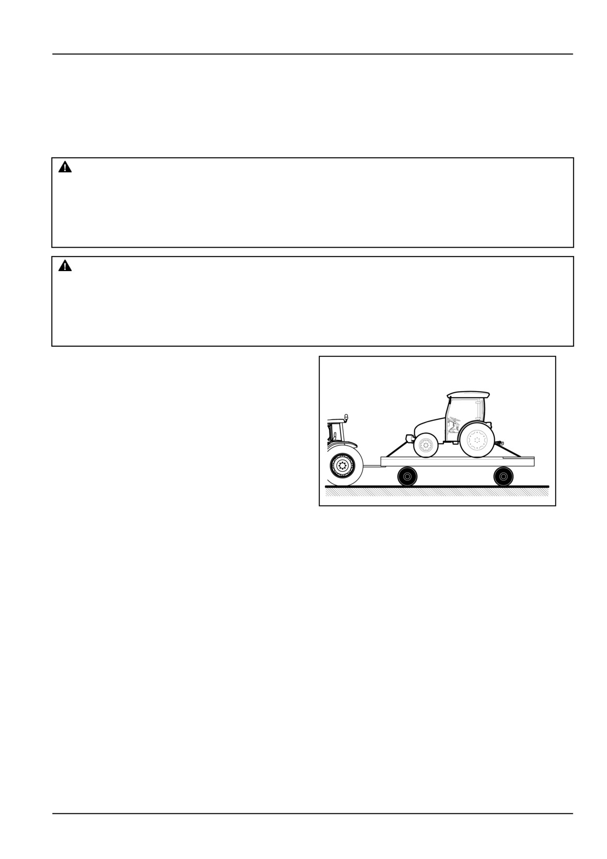
To transport the tractor it is necessary to load it onto a
suitable means of transportation; platform of the truck or
trailer equipped with a double axle.
Engage the Parking Brake.
Secure the tractor on the vehicle with suitable anchoring
belts or chains. Secure the rear of the tractor using the
tow bar or tow bar supports and the front of the tractor
using the towing hook.
1
DCUTLNEIT012S5A
NOTICE: Do not hook or connect chains around the front
resulting in possible damage to the bearings. The tur-
axle drive shaft, the power steering cylinders, the front
bocharger turbine must be prevented from rotating freely
axle itself or other parts of the tractor which could be dam-
(with the engine off), as the shaft bearings will not be lu-
aged either by the chains or excessive strain.
bricated.
On models fitted with the turbocharger, cover the exhaust
outlet to prevent the turbocharger rotating in the wind,
5-1
5 - TRANSPORT OPERATIONS
RECOVERY TRANSPORT
Towing the tractor
WARNING
Loss of control!
Only tow at safe speeds. Use caution when making corners or meeting traffic.
Failure to comply could result in death or serious injury.
W0126A
WARNING
Hazard to bystanders!
The operator must be the only person on the machine when towing. Make sure that nobody else is on
the machine or within its working range.
Failure to comply could result in death or serious injury.
W0259A
WARNING
Roll-over hazard!
Attempting to free a stuck machine can involve safety hazards: the stuck machine or the towing ve-
hicle may tip or overturn, or the tow bar may fail. Always use the proper towing equipment to free a
stuck machine.
Failure to comply could result in death or serious injury.
W0327A
WARNING
Flying object!
Do not use chains, cables, or rope to pull the machine. If the chain, cable, or rope breaks or slips, it
may whip with great force. Use only rigid drawbars or tow bars to pull your machine.
Failure to comply could result in death or serious injury.
W0328A
The tractor must only be towed for short distances, for example from inside a building to the outside. It must not be
towed for long distances on roads with heavy traffic.
Tow the tractor from the rear, using only the drawbar, the rear tow hitch or the three-point linkage device.
Tow the tractor from the front using the tow pin in the front ballast weights or front support.
Have an operator steer and brake the tractor when necessary.
To avoid damaging the transmission or other components that turn but are not lubricated during towing, observe
the following:
• position the gear and range levers in neutral;
• only tow for short distances;
• keep speed below 8 km/h (5.0 mph);
• if possible, run the engine to lubricate the power steering components.
5-2
6 - WORKING OPERATIONS
6 - WORKING OPERATIONS###_6_###
FOUR WHEEL DRIVE (4WD)
Four-wheel drive with electro-hydraulic control
Only SuperSteer™ axle
Front−wheel drive can increase the tractor’s grip on the surface: the benefits of this are particularly noticeable when
working on uneven, muddy or slippery surfaces, on ploughed ground or in difficult conditions.
Manual engagement
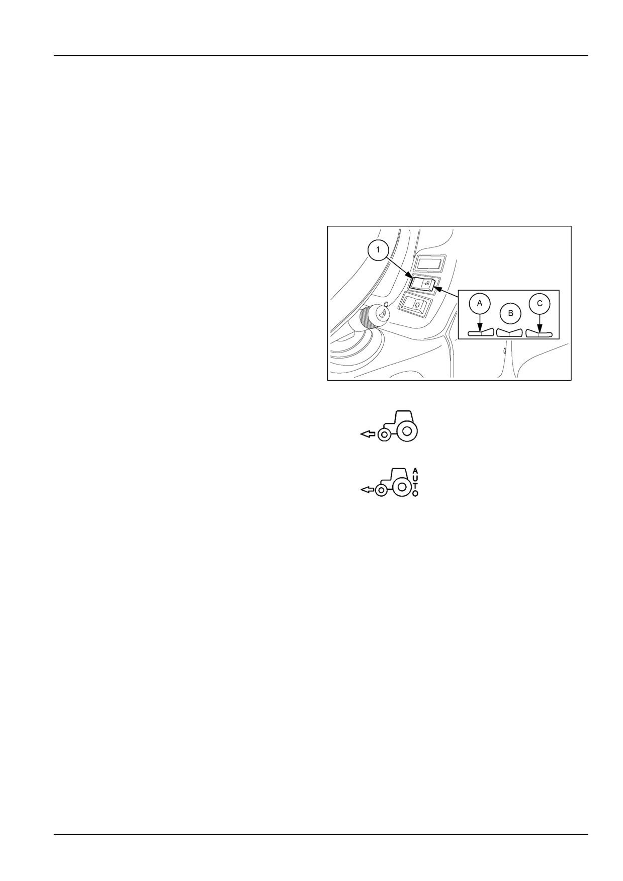
Engage four−wheel drive by pressing button (1) fig. 1 onto
(A). When released, the button returns automatically to
position (B).
In this position, front−wheel drive will be permanently en-
gaged; indicator (1) fig.
1 will illuminate to show that
front−wheel drive is engaged. To disengage, press the
button to position (A) once more.
Automatic engagement
By switching button (1) fig. 1 to position (C) indicator
MOIL13TR00949AA
1
(3) will illuminate, signalling that automatic four−wheel
drive has been selected. When released, the button
returns automatically to position (B). Four−wheel drive
2
engagement will be signalled by indicator (2) on the
control panel. This automatic function disengages
four−wheel drive under the following conditions:
• with speed above 15 km/h (9.3 mph);
3
or
• with steering angle greater than 30 °
To disengage automatic operation, press the push− but-
ton to position (C). Indicator (3) will switch off.
NOTE: It is recommended to use automatic four− wheel drive when present.
NOTICE: Four−wheel drive is engaged automatically time, irrespective of the selection made with both ver-
whenever the brake pedals are operated at the same sions. In this case only the indicator (2) stays on.
NOTE: Do not use four−wheel drive when driving on roads, as this increases wear on the front tires.
6-1
6 - WORKING OPERATIONS
DIFFERENTIAL LOCK
Electrohydraulic differential lock
DANGER
Steering is difficult with the differential lock engaged. An accident could result.
During field operation, use the differential lock for traction improvement but release for turning at row
end. Do not drive at high speeds or on roads with the differential lock engaged.
Failure to comply will result in death or serious injury.
D0023A
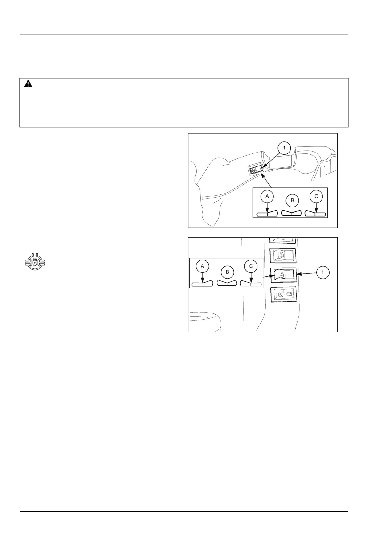
The differential allows the drive wheels to rotate at differ-
ent speeds when the tractor is turning.
The differential is fitted with an electro-hydraulic locking
device, operated by switch (1);
• Figure 1 models without cab
• Figure 2 models with cab.
To activate differential locking, put the switch (1) into po-
sition (A). When the switch is released, it returns to the
middle position B.
NOTE: If the switch is in position (C), to activate the differ-
ential lock it is necessary to move onto the middle position
MOIL13TR01001AA
1
(B) and put it into position (A).
Differential lock engagement is highlighted
with the amber warning light on the
instrument panel coming on.
To disengage the differential lock, reduce the tractor
speed and put the switch (1) into position (C). The switch
remains held in position (C).
The differential lock is also disengaged when pressing the
brake pedals.
MOIL13TR00466AA
2
It is advisable to lock the differential in the following situations:
• When ploughing, to prevent the wheel that is not in the furrow
from slipping.
• When one of the drive wheels is on uneven, muddy or slippery ground and tends to slip.
NOTICE: If the differential fails to disengage, momentarily press the footbrake that acts on the outside directional
wheel.
NOTE: Only lock the differential in the event of one of the two wheels slipping excessively. Do not keep the differential
locked unnecessarily as this wastes power and can cause damaging stresses in the transmission system, tyre wear
and steering problems.
6-2
6 - WORKING OPERATIONS
Mechanical differential lock
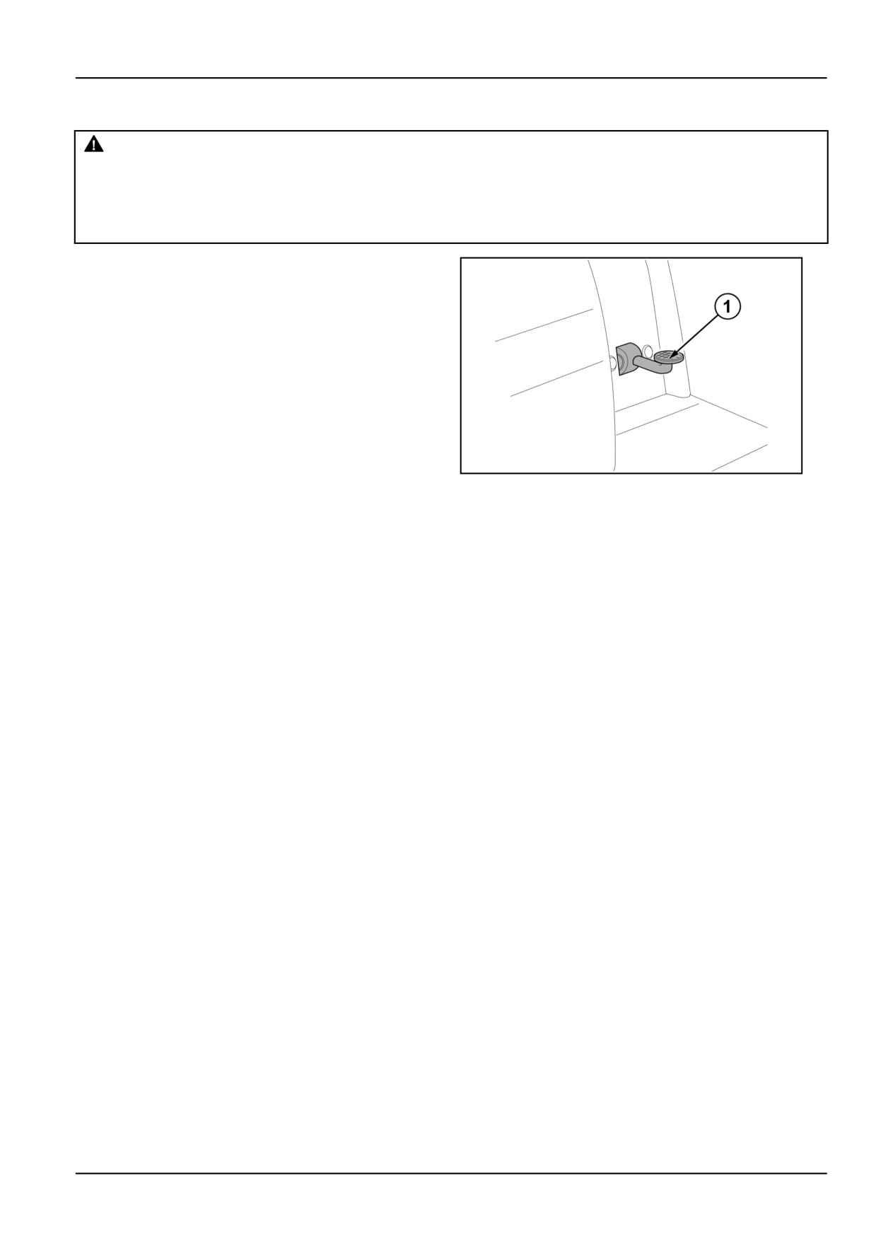
DANGER
Steering is difficult with the differential lock engaged. An accident could result.
During field operation, use the differential lock for traction improvement but release for turning at row
end. Do not drive at high speeds or on roads with the differential lock engaged.
Failure to comply will result in death or serious injury.
D0023A
The differential allows the drive wheels to rotate at differ-
ent speeds when the tractor is on a bend.
The differential has a locking device, controlled by a
foot pedal (1) It is advisable to lock the differential in the
following situations:
• when ploughing, to prevent the wheel that is not in the
furrow from slipping;
• when one of the drive wheels is on uneven, muddy or
slippery ground and tends to slip.
DCSPNEGB046S3A
1
To lock the differential, reduce tractor speed and press pedal (1). The differential will remain locked.
To release the lock, press one of the two brake pedals.
6-3
6 - WORKING OPERATIONS
REMOTE VALVES
General safety rules
WARNING
Unexpected movement!
When starting the machine engine, make sure the remote valve levers are in the correct position BE-
FORE you operate the key switch. This prevents an attached implement from moving unintentionally.
Failure to comply could result in death or serious injury.
W0433A
WARNING
Escaping fluid!
Do not disconnect hydraulic quick coupler under pressurized conditions. Make sure all hydraulic
pressure is removed from the system before disconnecting hydraulic quick coupler.
Failure to comply could result in death or serious injury.
W0095A
WARNING
Pressurized system!
Before disconnecting the couplers, you must:
-lower the connected attachments,
-stop the engine,
-move the control levers forward and backward to discharge pressure from the hydraulic system.
Failure to comply could result in death or serious injury.
W0389A
WARNING
Pressurized fluid can penetrate the skin and cause severe injuries.
Keep hands and body away from any pressurized leak. DO NOT use your hand to check for leaks. Use
a piece of cardboard or paper. If fluid penetrates the skin, seek medical attention immediately.
Failure to comply could result in death or serious injury.
W0158A
The main causes for poor operation or breakage of the quick couplers are:
• dirt
• type of male quick coupler not compatible, or damaged (dents, for instance)
6-4
6 - WORKING OPERATIONS
Rear remote control valve(s)
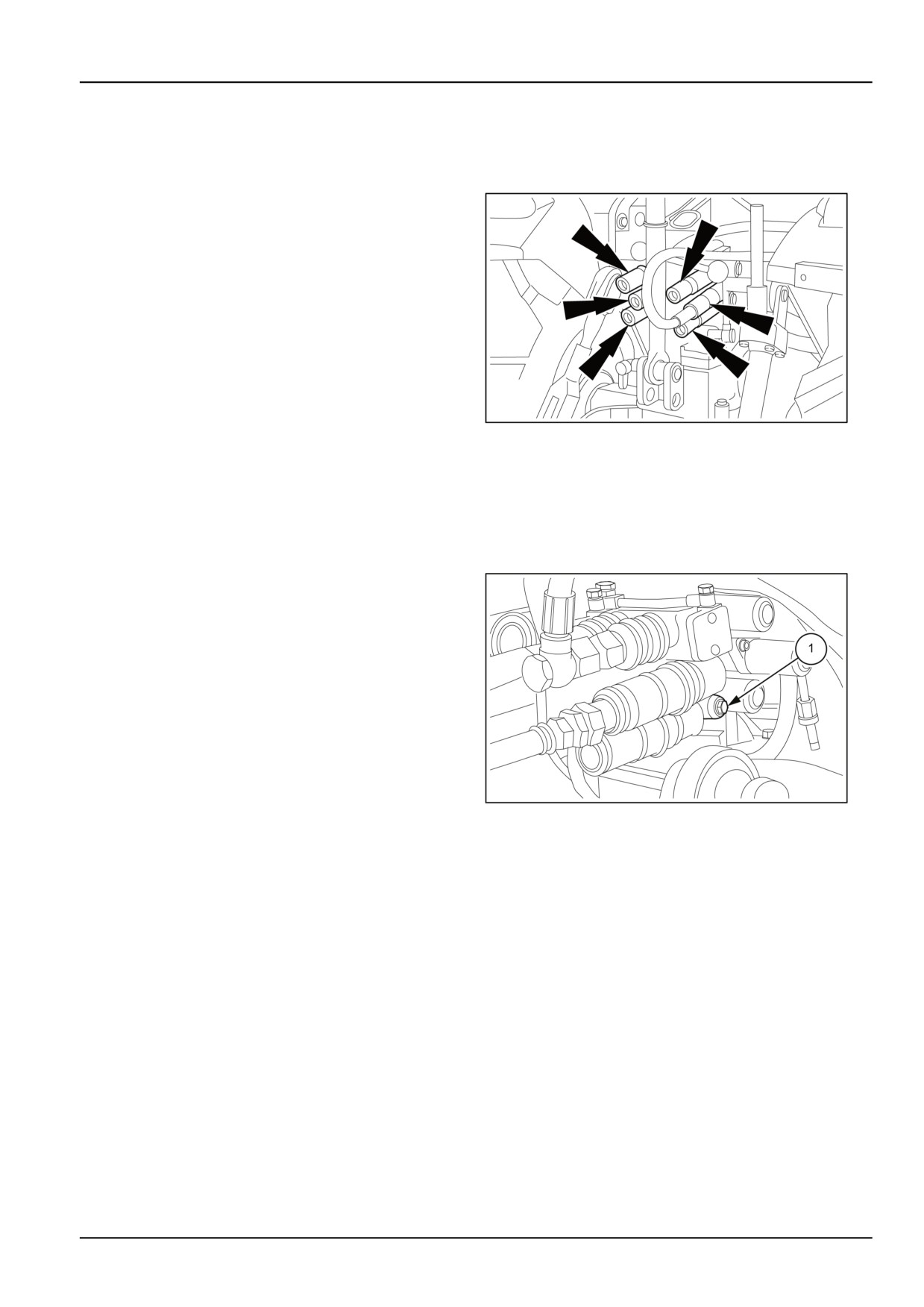
Before removing the protective caps for connecting the male couplings, remove all the debris that has accumulated
on the pressure points to avoid contaminating the hydraulic system.
Quick coupler
One, two or three control valves using the same oil as
the hydraulic lift circuit to which they are connected can
be fitted to your tractor for remote control of single-acting
and double-acting cylinders.
Each valve has two 1/2” quick−fitting female “Push− Pull”
couplers which can be connected to pressurised male
couplers, available as an optional. You can thus connect
the control cylinder lines with two hands.
Push them in to fit them and pull them out to release
them from the female couplers, but only after first:
MOIL13TR00839AA
1
• stopping the engine
• lowering any implements connected to the lift;
• thoroughly cleaning the two mating parts.
NOTE: When not using the female couplers, protect them
with the plastic caps.
Single/double-acting switching
To switch the control valves to:
• single−acting, slacken screw (1) near to the valve con-
trol lever pivot until it stops.
• Double-acting, fully tighten the screw (1).
When using single-acting, in order to quickly identify the
coupler to which the implement is to be connected, ac-
tuate the distributor lever and observe the two lines to
which the couplers are connected: the line carrying the
oil should move.
MOIL13TR00841AA
2
For greater safety, check that the line to which the im-
plement is connected using single-acting, is the line on
the valve body connected furthest from the change-over
screw.
6-5
6 - WORKING OPERATIONS
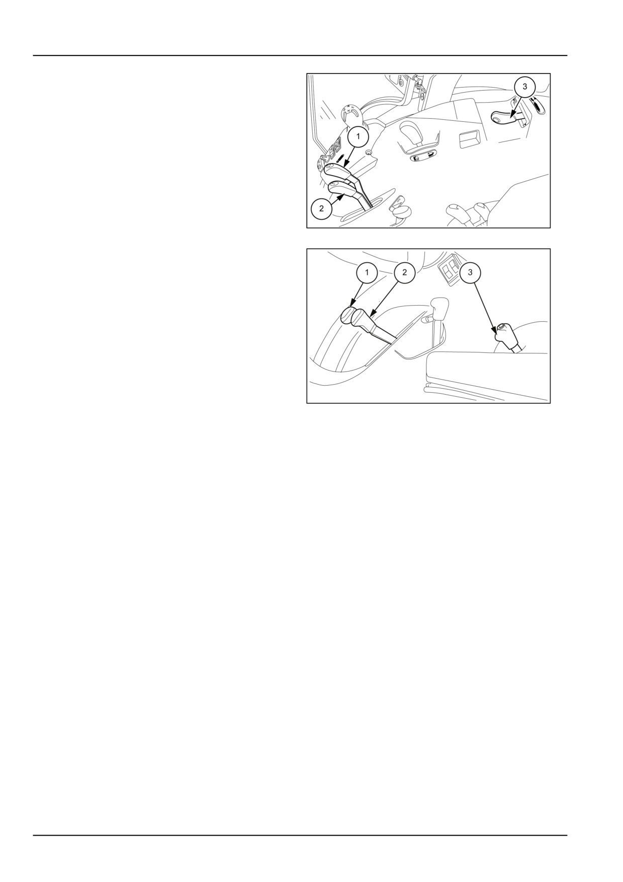
Auxiliary control valve levers for models
with mechanically controlled hydraulic lift
Control levers (1) and (2) have two positions, as well as
the central neutral position:
• forward = down;
• back = up.
The control lever (3) can be in two positions, excluding
the central neutral position:
• to the right = lowering
• to the left = lifting
MOIL13TR00453AA
3
Auxiliary control valve levers for models
with electronically controlled hydraulic lift
Control levers (1), (2) and (3) have two positions, as well
as the central rest position:
• forward = down;
• back = up.
4
MOIL13TR00848AA
Distributors with automatic release
NOTE: Each control lever is provided with a coloured
plastic plug that enables identifying the coupling to which
When operated, the lever is held in position by a me-
it is connected (with a plastic plug of the same colour).
chanical catch that enables having the implement make
NOTICE: Leaks of pressurized hydraulic fluid can pene-
the required movement without it being necessary to hold
trate the skin and cause severe injuries:
the lever on that working position manually. In this way it
- Never use hands to locate a leak,
is possible to perform other operations with both hands.
use cardboard or paper.
When the pressure set in the hydraulic system is reached,
- Switch off the engine and discharge the pressure before
the control lever is automatically released from the me-
connecting or disconnecting pressurised lines.
chanical catch and returns to the neutral position.
- Tighten all connectors before starting the engine or pres-
surising the hydraulic system. If fluid penetrates the skin,
Control valves with float setting
seek medical assistance immediately to prevent serious
injury
The tractor can be fitted with float setting valves for imple-
ments that require this function. To select the float setting,
push the relevant valve lever fully forward, past the first
detent, and then push fully forward. A catch will keep the
lever hooked in the float position. To release the control
lever from the float setting, pull upward to return it to the
neutral position.
6-6
6 - WORKING OPERATIONS
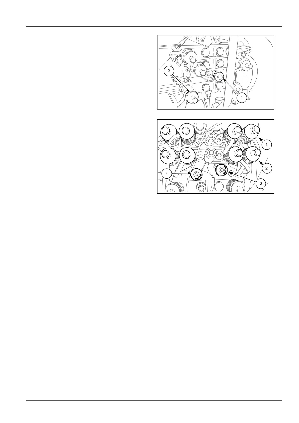
Flow divider
Version with one flow control knob
The knob (1) is used to control the oil flow rate of the
remote valve (2), the remaining (excess) flow rate will be
diverted to the other valves.
MOIL13TR00594AA
5
Version with two flow control knobs
The knob (3) is used to control the oil flow rate of the top
group of remote valves (1) or the lift.
The remaining (excess) oil flow from the top remote valves
or the lift will be diverted to the return line.
The knob (4) is used to control the oil flow rate of the
bottom group of remote valves (2).
The remaining (excess) oil flow will be diverted to the top
remote valves (1) or to the lift.
MOIL13TR02160AB
6
6-7
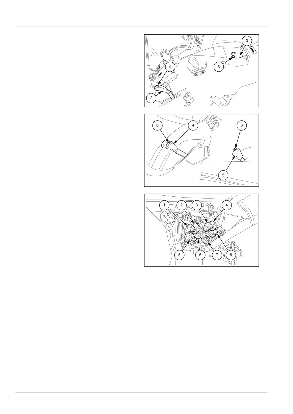
6 - WORKING OPERATIONS
Split control spool valves (with switch)
On all the models, the control levers (2) and (3) for models
with a mechanical lift or (4) and (5) with an electronic lift
can be equipped with a button (6) so that each of them
can control two spool valves.
Mechanical Lift
lever (2);
• When the lever is moved forwards and backwards,
it commands the implement connected to the spool
valves (5) and (8) fig. 9;
MOIL13TR00452AA
7
• Press the button (6) on the lever and move it forwards
or backwards to command the implement connected to
the spool valves (6) and (7) fig. 9;
lever (3);
• When the lever is moved to the right or left, it commands
the implement connected to the spool valves (1) and (4)
fig.
9;
• Press the button (6) on the lever and move it to the
right or left to command the implement connected to
the spool valves (2) and (3) fig. 9;
Electronically controlled lift
MOIL13TR00850AA
8
Handle (4)
• When the lever is moved forwards and backwards,
it commands the implement connected to the spool
valves (5) and (8) fig. 9;
• Press the button (6) on the lever and move it forwards
or backwards to command the implement connected to
the spool valves (6) and (7) fig. 9;
Handle (5)
• When the lever is moved forwards and backwards,
it commands the implement connected to the spool
valves (1) and (4) fig. 9;
MOIL13TR00851AA
9
• Press the button (6) on the lever and move it forwards
or backwards to command the implement connected to
the spool valves (2) and (3) fig. 9.
6-8
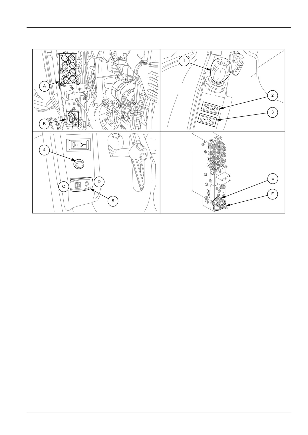
6 - WORKING OPERATIONS
Electrohydraulically controlled side hydraulic valves
MOIL13TR01009FA
1
Machines equipped with a cab have a block of distributors for remote controls fixed on the right-hand side of the
driver's seat, controlled electronically.
The block of distributors is split into two sections:
• Section (A) is composed of four pairs of distributors with a controlled flow rate.
• Section (B) is composed of a pair of distributors for connecting hydraulic motors with a maximum flow rate of 33 l/
min (5 US gpm) controlled by a potentiometer.
The set of controls is secured inside the cab on the right-hand mudguard.
1. Joystick for controlling the distributors of section (A).
2. Distributor activation switch on line (X) .
3. Distributor activation switch on line (Y) .
Both switches, when pressed on a certain colour, activate the corresponding pair of distributors marked with the same
colour.
On the bottom of the console, there are the controls (4) and (5) for managing the hydraulic motors connected
to the pressure taps (B).
4. Flow control potentiometer for the oil to the sockets (B) from 0 to 33 l/min (5 US gpm).
5. Hydraulic motor control switch.
Press the switch onto position (D) to turn on the hydraulic motor, or position (C) to turn it off.
NOTE: For the pair of distributors for connecting hydraulic motors, the distributor (E) is for delivery and the distributor
(F) for the return line.
6-9
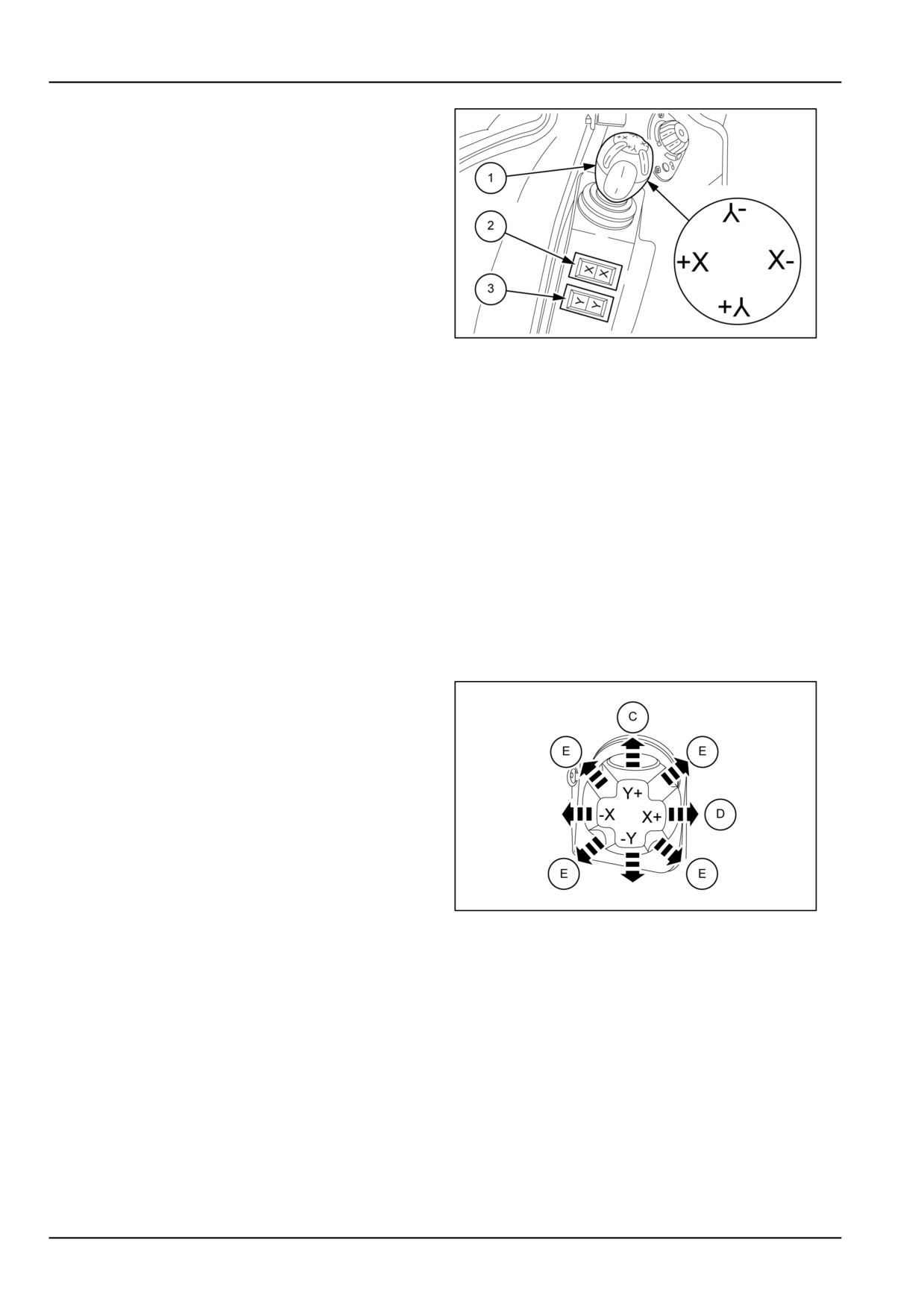
6 - WORKING OPERATIONS
Operation
When the joystick (1) is operated with a crosswise move-
ment, it operates the distributors on axis (X) and on axis
(Y) .
The same lever (1) when operated diagonally enables si-
multaneous operation of two variable flow rate distribu-
tors.
Underneath the joystick there are the switches (2) and (3)
that activate the distributors on the line (X) or (Y).
Press the switch (2) to the right or left on a specific colour
to activate the pair of distributors marked with the same
MOIL13TR01011AA
2
colour on the line (X)
Press the switch (3) to the right or left on a specific colour
to activate the pair of distributors marked with the same
colour on the line (Y)
Operation of the distributors of the corresponding line is
inhibited in the central position.
Connecting the Implement
Press the buttons (2) or (3) on a specific colour to activate
the corresponding pair of distributors of the same colour
on the line (X) or (Y) .
Connect the oil supply tube to the distributor marked (+)
and the return line on the distributor of the same colour on
the mark (-).
Joystick operation
To operate the connected implements observe the
following instructions:
• Switch (2) pressed to the right or left: line distributors
(X) on.
• Move the lever (1) to the right (X+) to lift, or to the left
(X-) to lower the connected implements. When the lever
is all to the right in position (D) it is held by a catch to
enable the float position.
• Switch (2) in the middle position: line distributors (X) off.
• Switch (3) pressed to the right or left: line distributors
MOIL13TR01010AA
3
(Y) on.
• Move the lever (1) forwards (Y+) to lift, or to the left (Y-)
to lower the connected implements. When the lever is
all forward in position (C) it is held by a catch to enable
the float position.
• Switch (3) in the middle position: line distributors (Y) off.
NOTE: A diagonal movement in the directions (E) to-
gether with a crosswise movement enables carrying out
multiple controls.
6-10
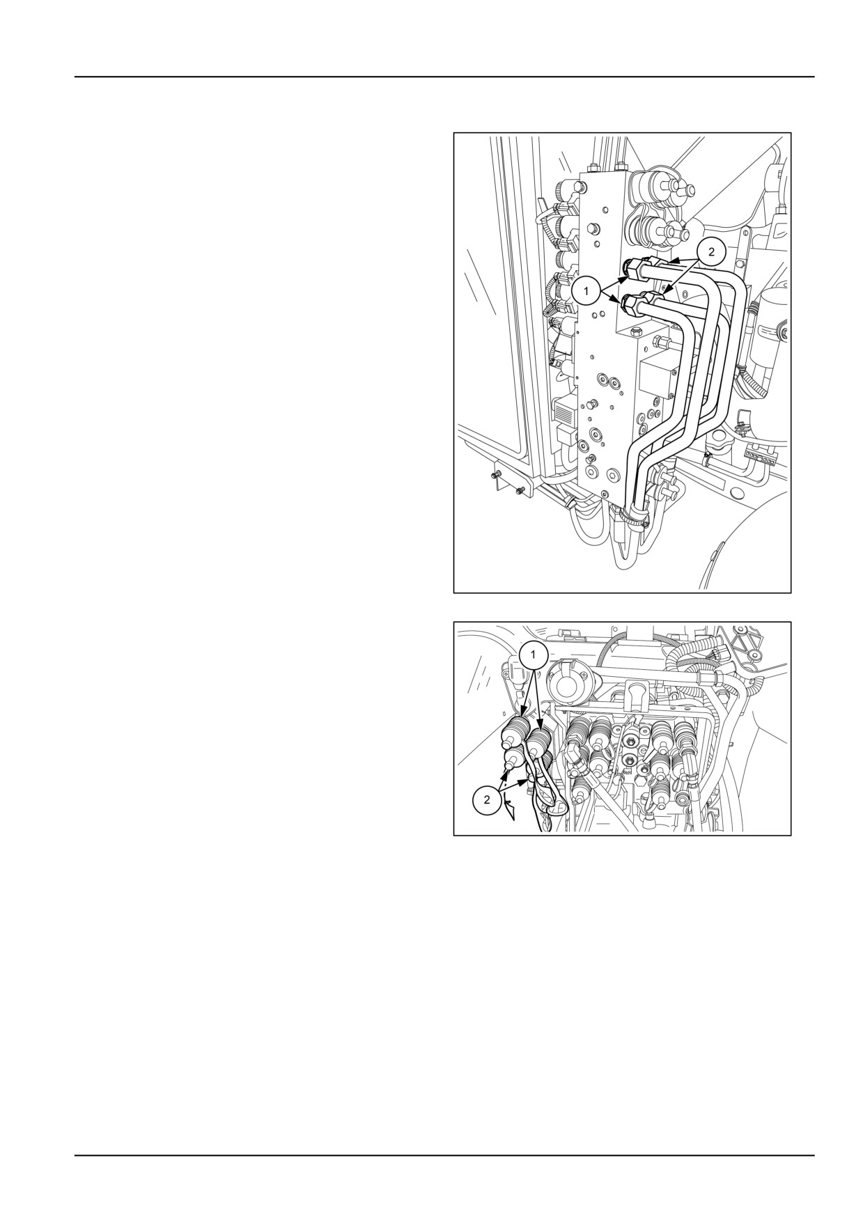
6 - WORKING OPERATIONS
Electrohydraulically controlled rear remote control valves
On request, two pairs of electro-hydraulically controlled
side spool valves can be used to supply the same number
of auxiliary rear hydraulic control valves.
1. Line control valves X, yellow
2. Line control valves Y, black
MOIL13TR00302BA
1
To work the two rear control valves, press the correspond-
ing colour on the relative line switch.
1. Yellow
2. Black
NOTE: Depending on the colors selected by the two
switches, the joystick controls simultaneously side and
rear remote control valves.
For joystick operation, see the previous chapter, “Electro-
hydraulically controlled side spool valves”.
MOIL13TR00376AA
2
6-11
6 - WORKING OPERATIONS
Side hydraulic valves
Only models with roll bars ROPS
WARNING
Pressurized system!
Before disconnecting the couplers, you must:
-lower the connected attachments,
-stop the engine,
-move the control levers forward and backward to discharge pressure from the hydraulic system.
Failure to comply could result in death or serious injury.
W0389A
WARNING
Pressurized fluid can penetrate the skin and cause severe injuries.
Keep hands and body away from any pressurized leak. DO NOT use your hand to check for leaks. Use
a piece of cardboard or paper. If fluid penetrates the skin, seek medical attention immediately.
Failure to comply could result in death or serious injury.
W0158A
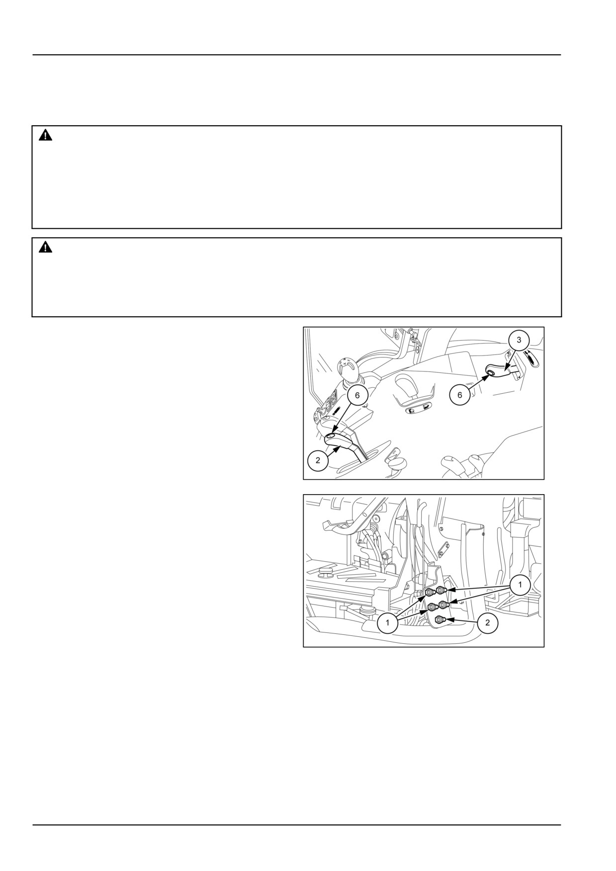
There are two distributors (1) figure 2 for fitting side or
front implements.
The distributors are controlled by the levers (2) and (3)
that command the rear distributors with the "DIVERTER"
function, that is to say by pressing the button (6).
With connected implements working with their own hy-
draulic motor, connect the outlet pipe to the socket (2) fig-
ure 2 for rapid oil discharge.
Operation
The levers shown in the figure, equipped with buttons
MOIL13TR00452AA
1
(6), can separately govern a number of implements
connected as described below:
• Move the levers forwards to lower or backwards to raise
the implements connected to the rear distributors with-
out using the buttons (6).
• Press the buttons (6) and move the levers forwards to
lower or backwards to raise the implements connected
to the side distributors.
MOIL13TR00610AA
2
6-12
6 - WORKING OPERATIONS
REAR POWER TAKE-OFF (PTO)
Power take off (PTO)
The power take-off fitted on the tractor is used to transfer power from the engine directly to the implement. It can be
controlled directly by the engine, or by the tractor's transmission. All tractors are fitted as standard with an independent
power take-off at 540 RPM.
The power take−off is available in the following versions:
• Independent, 540 RPM;
• Independent, 540/1000 RPM
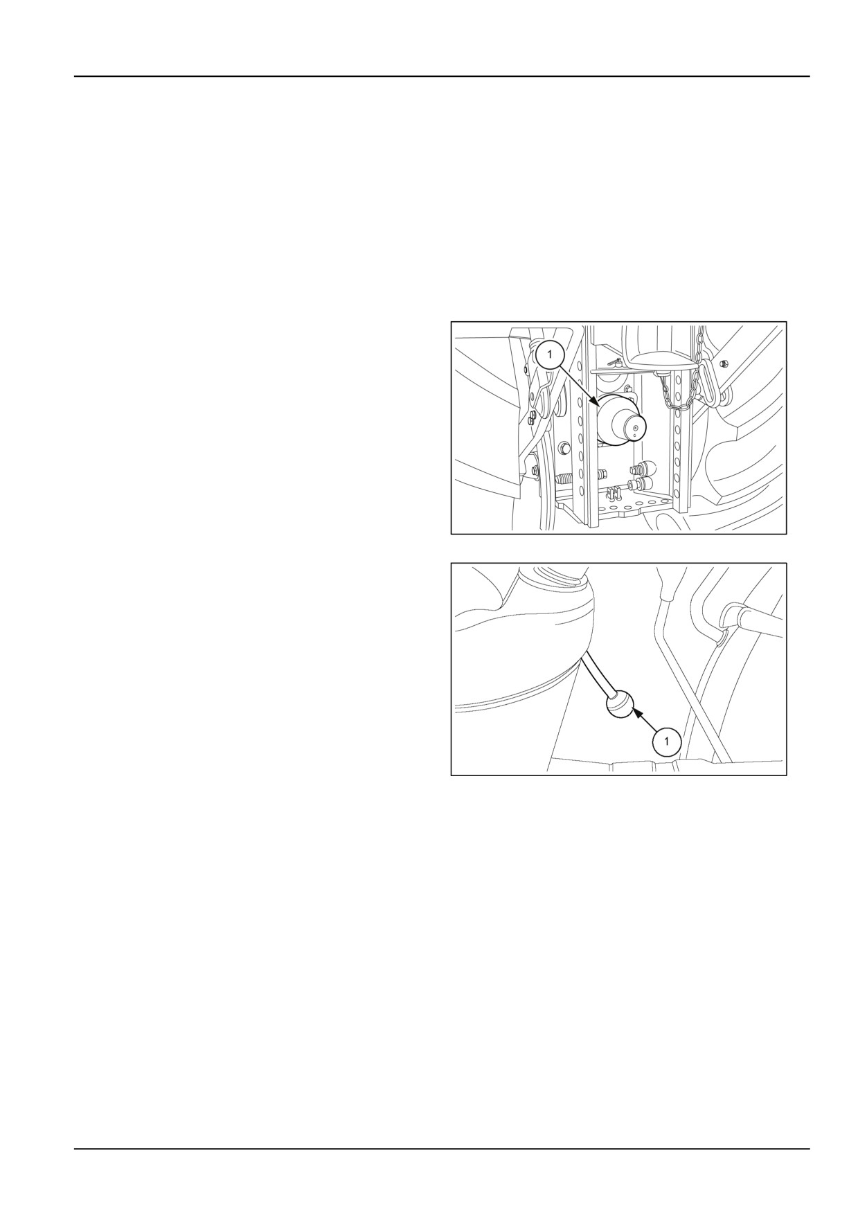
When the power take-off is not in use, always fit the safety
cover (1) on the splined output shaft.
NOTICE: When the power take-off is not being used or
when, with an implement connected to the power take-off
shaft, it has been switched off by means of the selection
lever, ensure that the control lever is in the disengaged
position. When the power take-off is not connected to
an implement, keep the control lever in the disengaged
position.
MOIL13TR00562AA
1
Independent PTO
In this case, operation is totally independent of the tractor
ground speed, and you can therefore:
• Stop the tractor without stopping the Power Take-Off.
• Stop the Power Take-Off without stopping the tractor
(by disengaging the Power Take-Off clutch).
To operate the Power Take−Off, proceed as follows:
• Check that the control lever (1) is completely lowered.
• Start the engine.
• Move the control lever (1) to the left and then up (com-
MOIL13TR00563AA
2
pletely raised).
To disengage the Power Take−Off move the control lever
(1) completely lowered.
NOTICE: When the Power Take-Off is not in use, keep
the control lever (1) completely lowered (disengaged po-
sition).
6-13
6 - WORKING OPERATIONS
540/1000 RPM Power Take-Off speed
Speed selection by changing output shaft
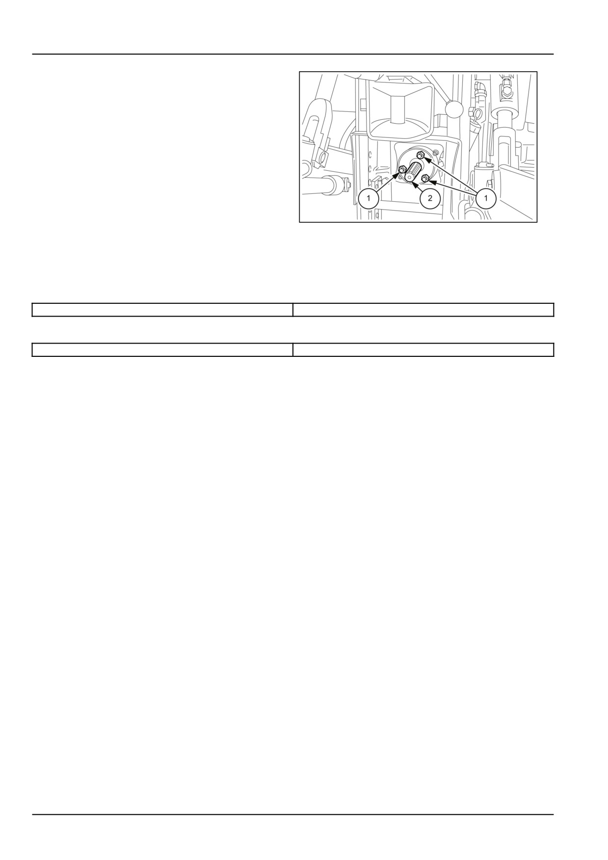
Passing from one speed to the other takes place
automatically by simply replacing the splined output
shaft (2);
• the speed of 540 RPM is obtained by fitting the 1 3/8 "
output shaft with 6 splines;
• the speed of 1000 RPM is obtained by fitting the 1 3/8 "
output shaft with 21 splines.
NOTE: When using the power take-off, and especially
MOIL13TR00566AA
3
when changing speeds, always make sure that the
tractor is fitted with the correct shaft for the speed se-
lected. When using any implement requiring a speed of
540 RPM, never select 1000 RPM, and vice versa.
Selected power take-off: 540 RPM
540 RPM with engine running at 2196 RPM
565 RPM with engine running at 2300 RPM
Selected power take-off: 1000 RPM
1000 RPM with engine running at 2260 RPM
1017 RPM with engine running at 2300 RPM
6-14
6 - WORKING OPERATIONS
FRONT POWER TAKE-OFF (PTO)
Front Power Take-Off (PTO) - Safety rules
WARNING
Entanglement hazard!
The Power Take-Off (PTO) guard must be installed when operating PTO-driven equipment.
Failure to comply could result in death or serious injury.
W0322A
WARNING
Entanglement hazard!
Do not wear loose clothing when operating Power Take-Off (PTO) driven equipment.
Failure to comply could result in death or serious injury.
W0337A
WARNING
Flying objects!
Do not use the implement at a higher Power Take-Off (PTO) RPM than recommended. Machine damage
due to vibration may occur, resulting in loose parts and flying debris.
Failure to comply could result in death or serious injury.
W0192A
WARNING
Moving parts!
Disengage the Power Take-Off (PTO), turn off the engine, and remove the key. Wait for all movement
to stop before leaving the operator's position. Never adjust, lubricate, clean, or unplug machine with
the engine running.
Failure to comply could result in death or serious injury.
W0112A
WARNING
Unexpected movement!
Disengage the Power Take Off (PTO) after each use. This prevents an attached implement from moving
unintentionally.
Failure to comply could result in death or serious injury.
W0423A
6-15
6 - WORKING OPERATIONS
Front Power Take-Off (PTO) - Operating
The front Power Take-Off (PTO) transfers engine power
directly to front mounted equipment via a 6 spline shaft.
The PTO shaft rotates anti-clockwise (as viewed from the
front)
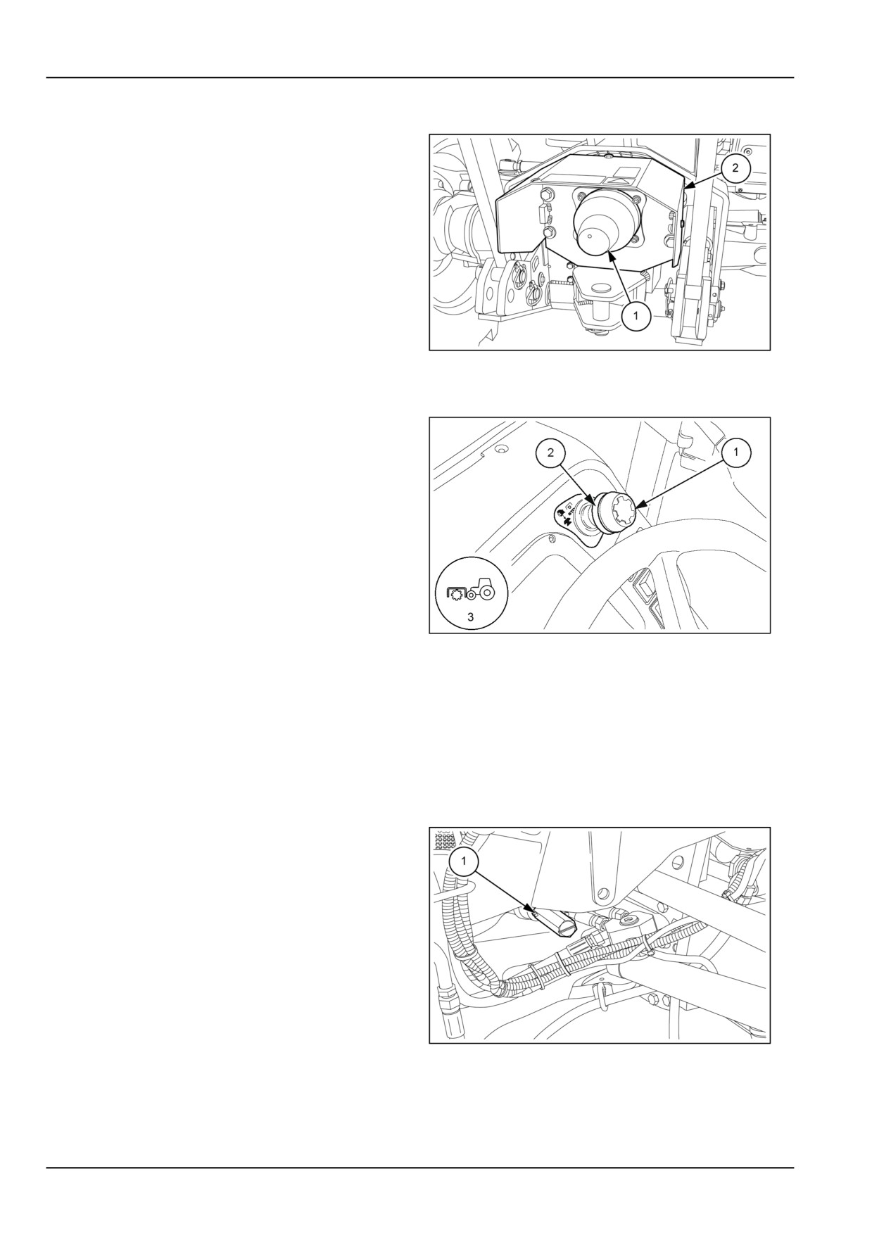
When the power take−off is not in use, always fit the safety
cover (1) on the splined output shaft as shown in the fig-
ure.
NOTICE: The Power Take-Off (PTO) guard (2) must be
always installed.
MOIL13TR00346AA
1
Operation
When starting the engine with pushbutton (2) ON, a warn-
ing light (3) informs the operator that the pushbutton must
be released. If the engine switches off with the PTO en-
gaged, an indicator light (3) tells the operator to deactivate
the command.
To engage the power take−off, lightly press push−button
(2) and pull the ring (1) upwards. Engagement is con-
trolled by an electromagnetic clutch. Indicator (3) remains
illuminated to indicate that the PTO is engaged. To disen-
gage the PTO, just press the knob (2) downwards.
MOIL13TR00950AA
2
NOTE: In the event of electrical malfunctions on the PTO, the ECU sends a signal to indicator (3).
NOTICE: In the event of slipping because of torque peaks, as a result of the implement jamming or particularly heavy
ground, the control unit automatically disengages the coupling. Under these conditions the indicator (3) flashes slowly
to indicate coupling disengagement. To re−engage the PTO, press the knob (2) fully down to disengage the clutch,
and then pull the knob upwards to re−engage. To return to normal operation the fault must be eliminated.
NOTE: For safety reasons, to avoid unnecessary rubbing, the device will not engage if the engine exceeds 1500 RPM.
If the power take−off is inadvertently engaged with the motor running at over 1500 RPM, the indicator (3) will flash
rapidly to warn that the motor revs must be reduced.
Power take-off drive coupling
NOTICE: In order to ensure longer life for the coupling
and the electromagnetic clutch, when the front PTO is not
being used, select the neutral position by turning screw
(1) on the right hand side anticlockwise.
MOIL13TR00347AA
3
6-16
6 - WORKING OPERATIONS
REAR HYDRAULIC LIFT
Hydraulic lift with mechanical control
The hydraulic lift system uses the transmission oil, which
Draft control
is supplied by a gear pump driven by the engine timing
gears.
Move position control lever (1) fully forward;
Set the desired implement depth in the ground by gradu-
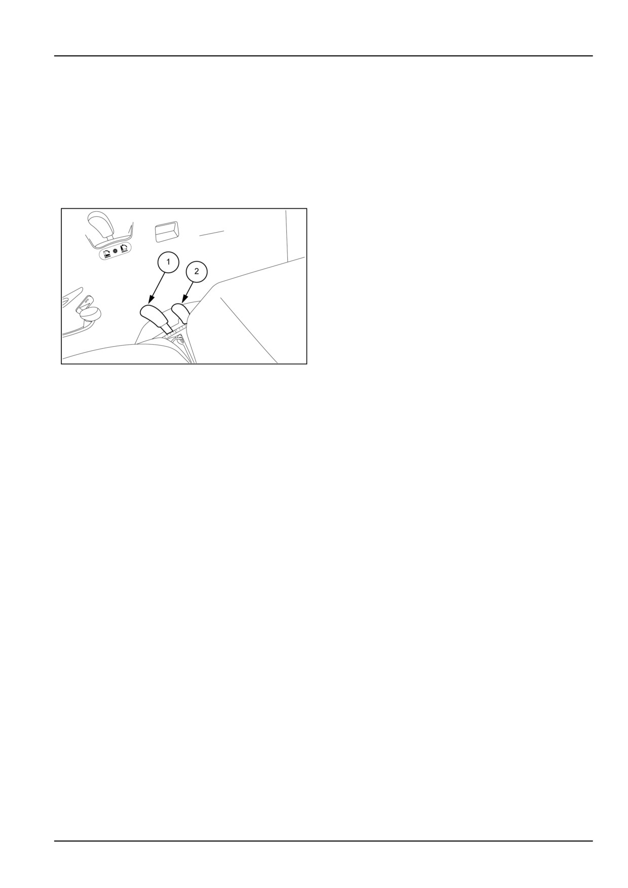
Operating Remote
ally shifting the draft control lever (2) forwards. The depth
reached by the implement is proportional to the traction
power which, in turn, is determined by the firmness of
the ground. In these conditions, the lift will automatically
maintain the traction power required from the tractor at a
constant level.
To raise and lower the implement at the headland or when
necessary, use the lever (1), do not change the position
of the lever (2). When the implement is lowered, to restart
work move the lever into the previous position to work with
the same settings.
Float function
MOIL13TR01423AA
1
To operate the lift in float mode, i.e. with free movement
1. Position control lever
of the arms for their full travel, move both levers (1) and
(2) fully forward;
2. Draft control lever
The lift should only be used to raise and lower the imple-
With the manually-operated hydraulic lift, there can be the
ment at the headland; to do this, operate only on lever (1).
following operating conditions.
Mixed position and draft control
Position control
Set the desired implement depth in the ground and find
Move draft control lever (2) fully forward.
the working depth required, as described for draft control.
Set the position of the implement, either in or above the
When the implement is set at the desired depth, gradually
ground surface, move the lever (1) forward to lower the
shift the position control lever (1) backwards, until the lift
implement and backward to raise it. The movement of
arms start to rise.
the implement will be proportional to the movement of the
lever.
Move the lever into the previous position to work with the
same settings.
To raise and lower the implement at the headland or when
necessary, use the lever (1), do not change the position
The lift operates in draft control but, at the same time, pre-
of the lever (2). When the implement is lowered, to restart
vents the implement from going too deep if less ground
work move the lever into the previous position to work with
resistance is encountered, which could result in unsuit-
the same settings.
able soil being brought to the surface.
6-17

6 - WORKING OPERATIONS
Lift-O-Matic® control - Operating
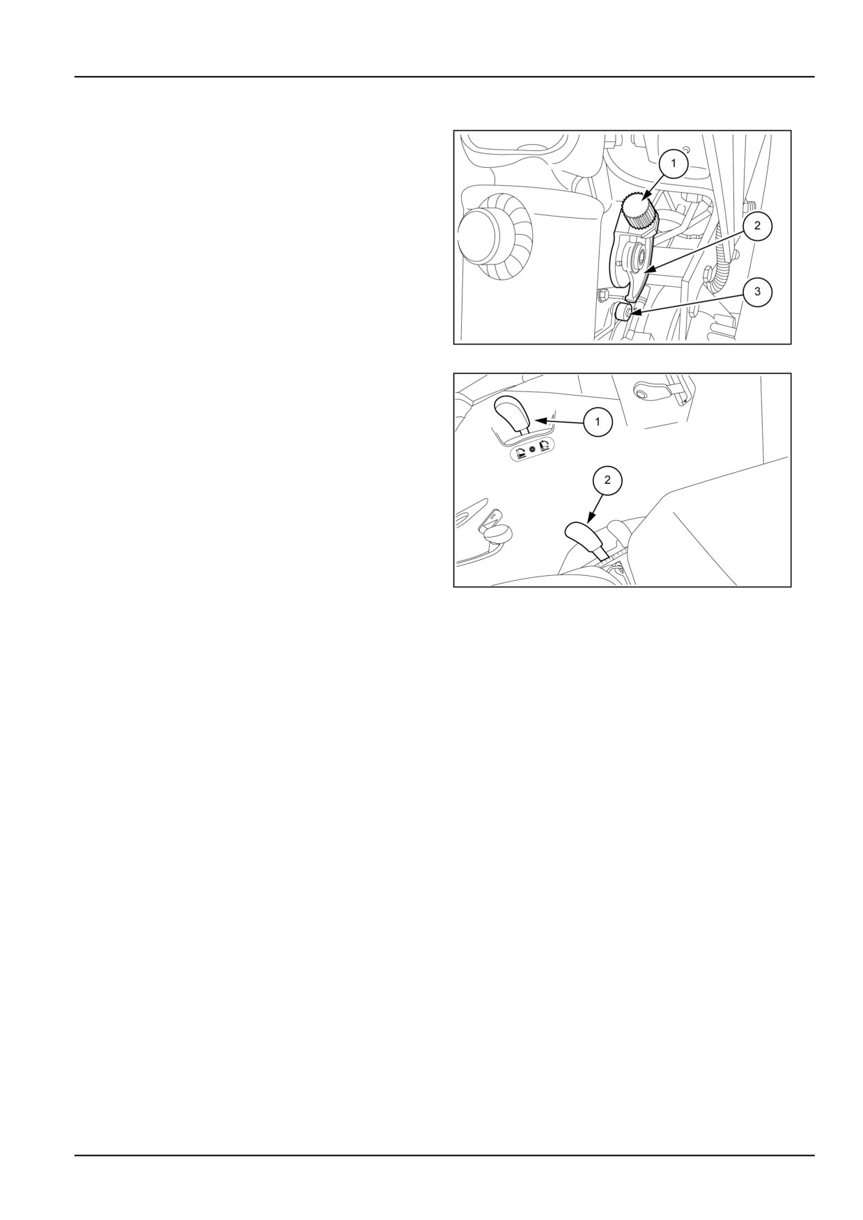
The lever (1) is used to position the implement in an infi-
nite number of positions. In both the lowering and raising
phases, the implement stops at the height corresponding
to the position where the lever is stopped.
Lifting
• Fixed neutral position of the lever.
The lever, when moved gradually rearwards, causes the
implement to raise up. In this condition, when the lever
is released it returns automatically to the central neutral
position, while the lift keeps the new set position.
• Fixed position of the lever on full height
MOIL13TR01422AA
1
The lever (1) moved fully back, quickly raises the imple-
ment up to its full height. In this condition the lever is held
in the fully back position.
Lowering
• Fixed neutral position of the lever
The lever, when moved gradually forwards, causes the
implement to lower. In this condition, when the lever is
released it returns automatically to the central neutral po-
sition, while the lift keeps the new set position.
• Fixed position of the lever on full lowering
The lever (1) moved fully forwards, quickly lowers the im-
plement down to the limit set beforehand with the position
control lever (2). In this condition the lever is held in the
fully forward position.
NOTE: The lever (1) is particularly useful to make small
adjustments in height of the lift arms. Move slightly to the
right or left lever to make these adjustments.
MOIL13TR01421AA
2
6-18
6 - WORKING OPERATIONS
Adjusting the height limit of lift arm travel
To achieve full lift height, turn the adjuster (1) fully anti-
clockwise until the cam (2) is clear of the lever (3).
MOIL13TR00375AA
3
To adjust the upward travel of the implement, follow
these guidelines:
1. Connect the implement to the lift arm swivel bushings;
2. Using the position control lever (2) fig.
4, raise the
implement to the desired height;
3. Move the lever (1) fig.
4 backwards to lift the imple-
ment.
4. Switch off the engine
5. Turn the adjuster (1) fig.
3 anticlockwise to take the
cam (2) into contact with the stop lever (3).
When you use the lever (1) fig. 3 of the Lift-o-Matic to
MOIL13TR01422AA
4
raise the implement, the cam (2) fig.
3 comes into con-
tact with the lever (3), stopping the implement from being
raised.
NOTE: The arm upward stroke limit adjustment only affects the operation of the Lift-o-Matic. If it were necessary to
raise the arms further, beyond the set limit, lift using the lift control levers.
NOTICE: When moving with the implement raised, the adjustment system described above will not prevent any jolting
of the implement due to passing over obstacles or rough ground. It is therefore recommended to travel at such a speed
as to avoid the problem of the implement hitch jolting.
6-19
6 - WORKING OPERATIONS
Hydraulic lift with electronic control
WARNING
Crushing hazard!
The lifting systems must be operated by qualified personnel who are aware of the correct procedures
to follow. Make sure all lifting equipment is in good condition, and all hooks are equipped with safety
latches.
Failure to comply could result in death or serious injury.
W0256A
WARNING
Crushing hazard!
Always lower the machine hydraulic lift and all other hydraulic equipment to the ground before shut-
ting off the engine and removing key.
Failure to comply could result in death or serious injury.
W0063C
The electronically controlled hydraulic lift offers considerable advantages over mechanical lifts as it features higher
levels of working precision and sensitivity and it is controlled by microprocessors.
The electronic control system enables selecting three different work modes:
• position control
• draft control
• Float operation
Unlike a conventional hydraulic lift, which is fitted with complicated lever mechanisms, the electronically controlled
hydraulic lift is equipped with electronic sensors that transmit variations in conditions to the electronic control unit,
which via the hydraulic system operates the lift arms.
For working safely
• Before operating them, make sure the control settings of the electronically controlled lift are as desired.
• Never leave the implement in the raised position when the tractor is stationary.
• With the tractor stationary and the engine running, the external controls located on the mudguards remain enabled.
Take care not to operate the controls inadvertently.
• The control unit is provided with self-diagnosis functions that signal any abnormalities in the control system.
• When possible, disconnect the implement or the part that needs welding from the tractor.
NOTE: To avoid damaging the electronic components, follow the instructions noted below when carrying out arc
welding on tractors fitted with electronic lifts or on connected implements.
• When possible, disconnect the implement or the part that needs welding from the tractor.
• Disconnect the two battery cables from the terminals.
• Connect the welding machine ground clamp as close as possible to the area where welding is to take place.
• If welding is to be carried out within 1 m (39.37 in) of the control unit, the unit must first be removed.
• While welding, make sure that the cables do not pass above or near electrical or electronic leads.
6-20
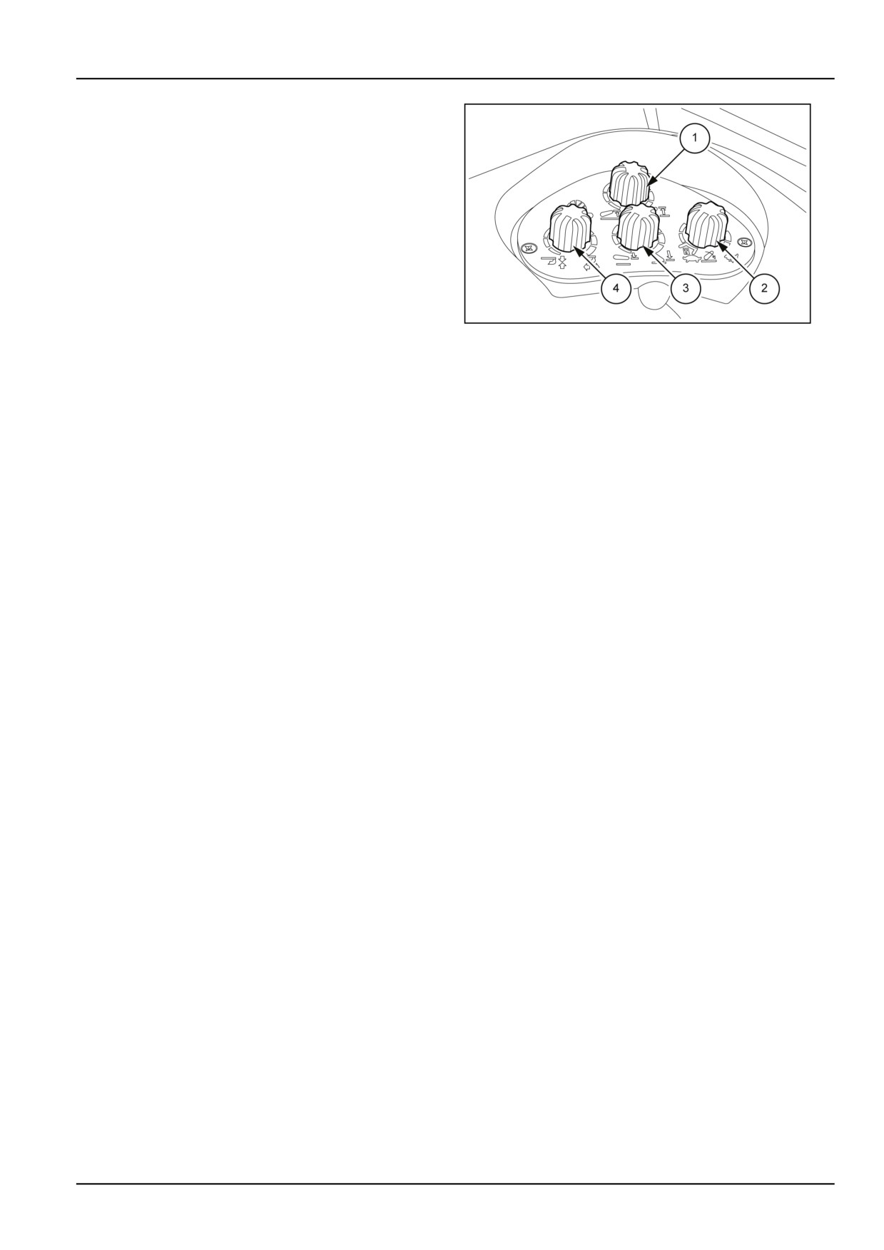
6 - WORKING OPERATIONS
Inside controls
The setting controls for the electronically controlled hy-
draulic lift are located to the right of the driving seat (see
page 33) and consist of four knobs:
Lift controls
1 Height limit adjustment control.
• Turn the knob completely clockwise to set the maximum
arm lift limit.
• Turn the knob completely anticlockwise to set the mini-
mum arm lift limit.
MOIL13TR00570AA
1
2 Lift arm drop rate adjustment control.
NOTE: With the drop rate control knob (2) turned com-
pletely anticlockwise, onto the padlock symbol, the lift will
• Turn the knob fully clockwise to set the maximum arm
remain locked in the position it had at that moment, irre-
drop rate.
spective of whether it was moving or not. In this condi-
• Turn the knob fully anticlockwise to set the minimum
tion it is possible to lift the implement, but not to lower
arm drop rate.
it. Turning the knob clockwise, towards the hare symbol,
progressively increases the drop rate.
3 Lowering limit adjustment control.
When the lift is at work, the drop rate is regulated by the
knob (2).
• Turn the knob completely clockwise to set the maximum
arm lowering limit.
NOTICE: When travelling on roads, turn the arm drop rate
control knob (2) completely anticlockwise, onto the tor-
• Turn the knob completely anticlockwise to set the mini-
mum arm lowering limit.
toise symbol and press the up/down switch onto the UP
position (A) fig.
3. The indicator (2) fig.
2 will begin to
4 Position/draft sensitivity control:
flash to signal that transport mode is activated. By oper-
ating controls (2) fig.
1 and (2) fig.
3 the lift will be dis-
• This knob enables adjusting the mixed position/draft
abled and will need to be reset, following the procedure
sensitivity control mode.
described on the next page.
• Turning the knob anticlockwise gradually reduces the
extent and frequency of the corrections made by the lift
in response to the changes in resistance provided by
the ground as the implement moves forwards.
• When this knob is turned completely anticlockwise, the
lift works only in position control mode.
6-21
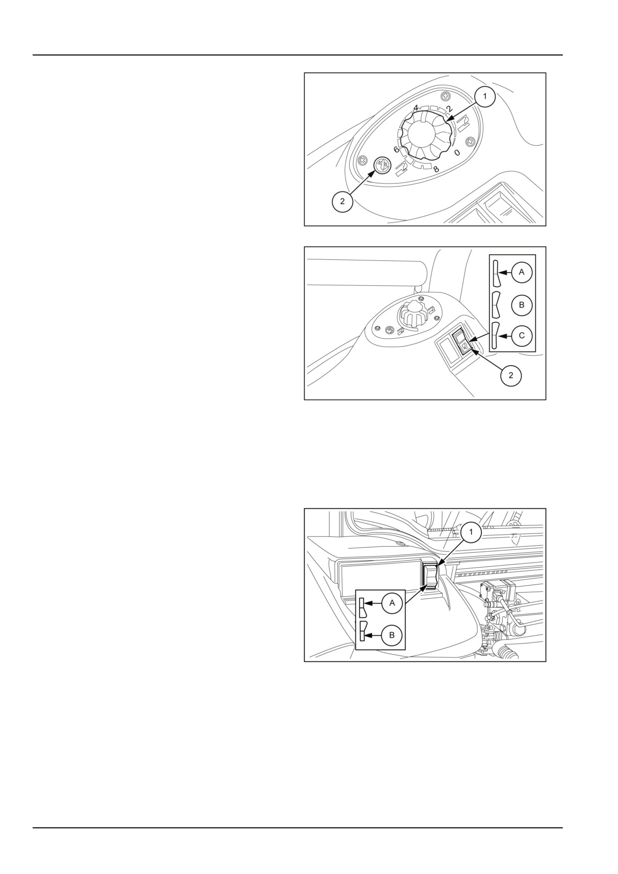
6 - WORKING OPERATIONS
Lower arms up/down control knob
The up/down movement of the arms is controlled by knob
(1). Turn the knob clockwise to raise the arms or anti-
clockwise to lower them.
To the left of the knob (1) there is an indicator light:
• indicator (2) indicates that the lift is momentarily dis-
abled, i.e.: the position of the knob (1) does not corre-
spond to the position of the arms, therefore the imple-
ment may neither be raised nor lowered. The external
controls can be used to vary the position of the imple-
ment.
MOIL13TR00812AA
2
Fast raise/lower switch
To raise and lower the implement, use the switch (2),
which has three positions:
• UP position (A)
• Work position (B)
• Fast ground entry position (C).
Use the position (C) at the headland to increase the im-
plement ground entry speed; when released the switch
automatically returns to the work position (B).
MOIL13TR00814AA
3
Lift arms reset procedure
To set the knob back in phase with the arms, check that
the fast up/down switch (2) fig. 3 is in position (B). Turn
the knob (1) fig. 2 completely clockwise (lifting), then turn
it slowly anticlockwise (lowering) until the indicator light
(2) goes out; now the movements of the knob (1) will be
in phase with the movements of the lower arms.
External controls
Up/down pushbuttons
The external lift controls (1) are located at the rear of the
tractor on both sides next to the tail lights. To enable the
controls, press the control buttons (1) into either position.
Switch to position (A) to raise, and position (B) to lower.
When using the external controls for the hydraulic lift,
all the central unit controls located in the cab are auto-
matically disabled. To re-enable these it is necessary to
perform the operations described under the heading "Lift
arms reset procedure".
MOIL13TR00573AA
4
6-22
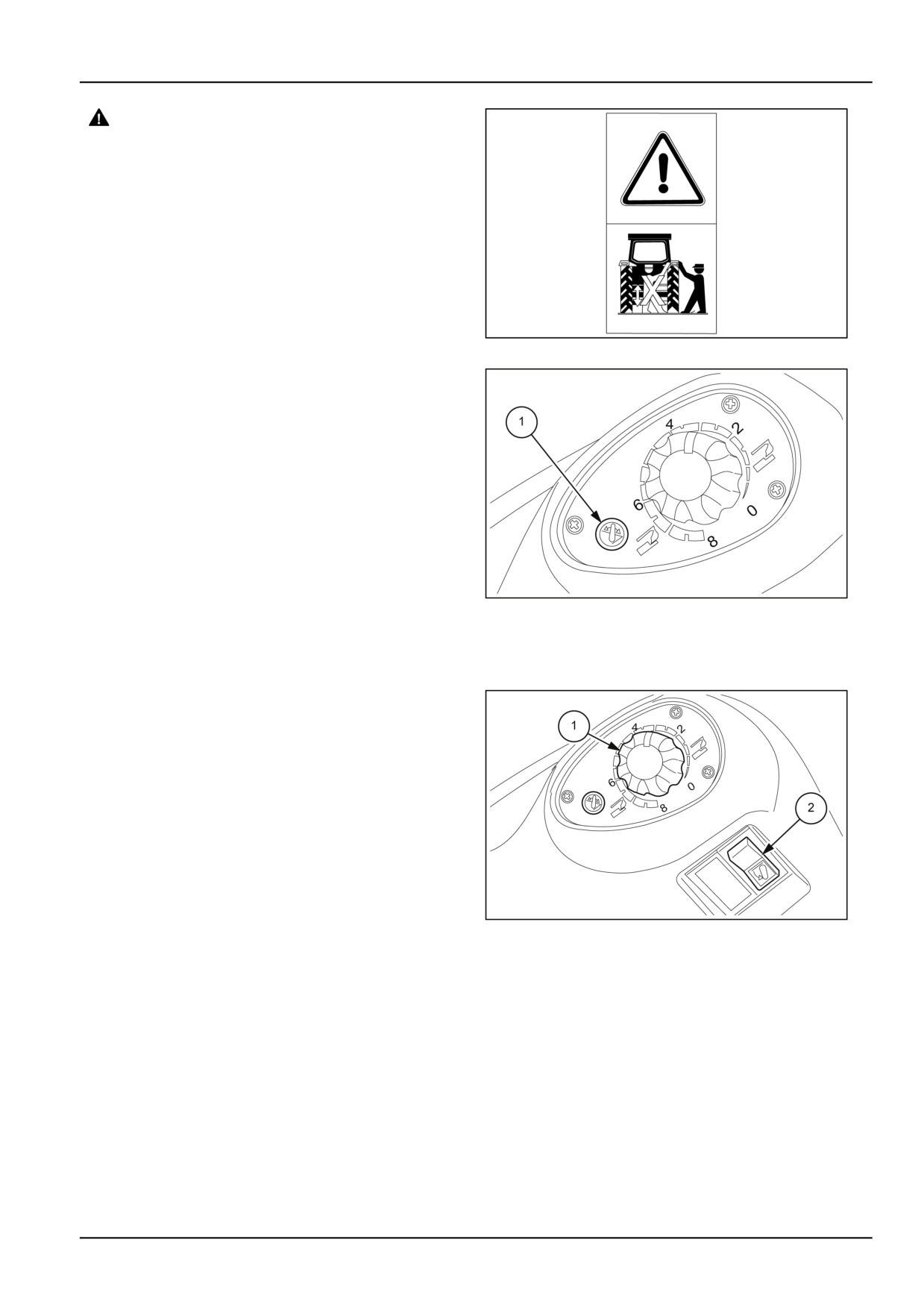
6 - WORKING OPERATIONS
DANGER
Crushing hazard!
Activate the external hydraulic control
switches only while standing to the side of
the machine (outboard of the rear tires). DO
NOT climb on the implement or between the
implement and the machine when the external
hydraulic controls are enabled.
Failure to comply will result in death or serious
injury.
D0009B
MOIL13TR00578AA
5
Using the lift
NOTE: When the indicator light (1) illuminates, this means
that the internal lift controls have been disabled as a result
of using the external controls on the mudguards, or that
errors have occurred that disable the lift. To return lift con-
trol to the internal controls it is necessary to perform the
operations described under the heading "Lift arms reset
procedure". When the control unit has been "re-enabled",
the indicator light will go out.
Before starting operations, set the upper and lower travel
limit and lift arm drop rate adjustment knobs in the most
suitable positions for the work to carry out.
MOIL13TR00817AA
6
NOTICE: When setting the implement for the first time,
keep the lower lift arms drop rate knob in the slow lowering
position to prevent damaging the implement or causing
injury.
Position control
To operate in position control mode, turn the knob (1) fig.
1 fully counter-clockwise and set the working depth using
the lower arm up/down control knob (1) fig.
7, rotating
clockwise to raise and counter-clockwise to lower.
To lift and lower the implement, use the fast up/down
switch (2) fig. 7; when lifting, the implement will be posi-
tioned at the height previously set with the lift limit control,
whereas when lowering it will go into the previously set
work position, within the limits set by the lowering limit (3)
fig.
1.
MOIL13TR00819AA
7
NOTE: In the event that the position selected with the
knob (1) fig. 7 requires a movement beyond the limits set
with the upper and lower travel limit knobs (1) and (3) fig.
1, lower arm travel will stop at the limits set.
If the drop rate control knob is turned completely anticlock-
wise, onto the padlock symbol, the arms will stay locked
in their present position and will no longer be able to be
lowered. If the push-button (2) fig. 3 is in position (A), the
external controls will be disabled too. Set then the most
suitable drop rate.
6-23
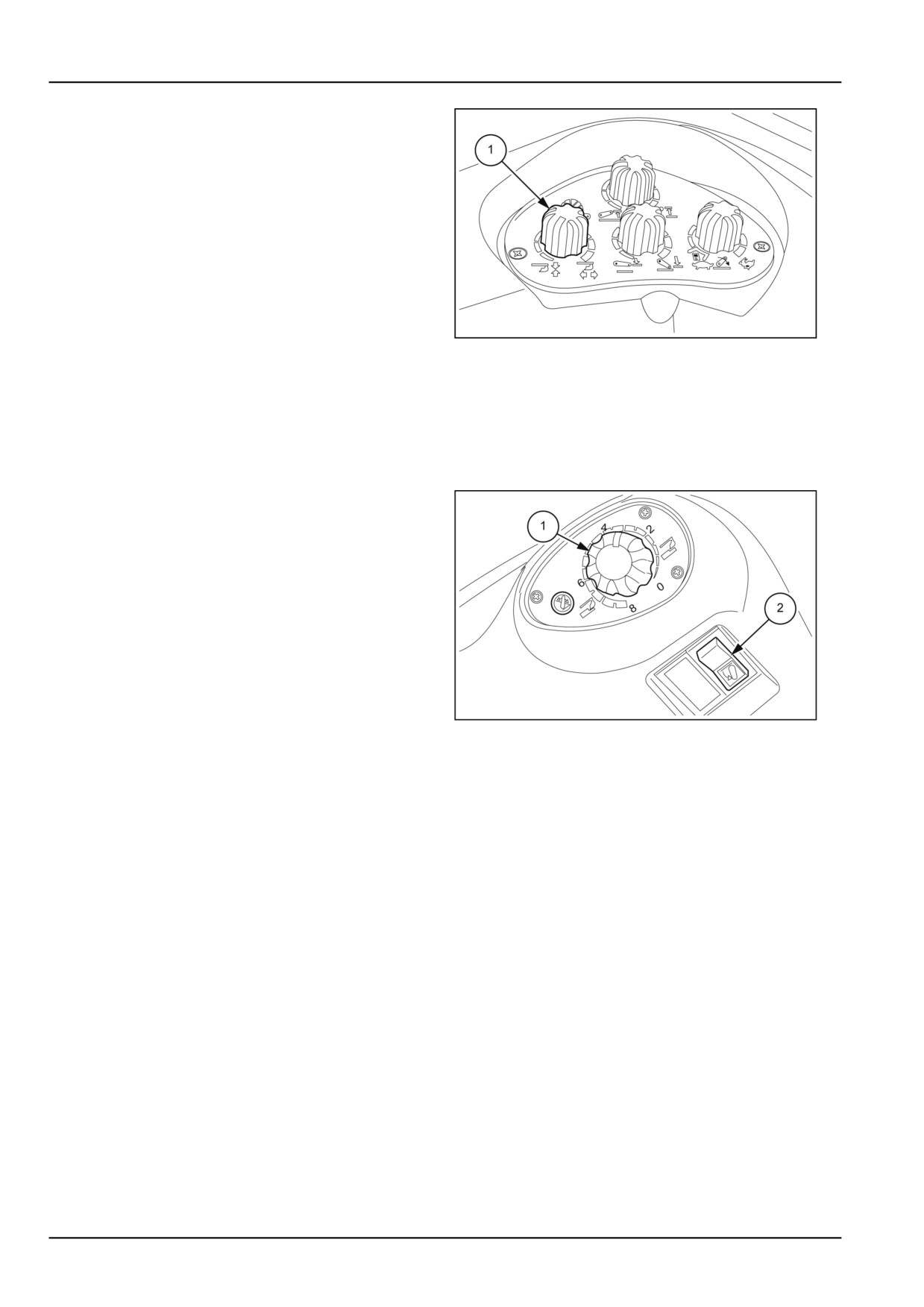
6 - WORKING OPERATIONS
Draft Control
To work in draft control mode, set the position/draft sensi-
tivity knob (1) to an intermediate position, bearing in mind
that by turning it clockwise the frequency and extent of
corrective interventions caused by tractor draft variations
on the implement will increase.
With the knob (1) fig. 8 turned fully clockwise (completely
to the right, the decal shows two horizontal arrows point-
ing in opposite directions), a more sensitive adjustment
will be obtained, therefore variations in ground density
will result in more frequent interventions by the hydraulic
system and consequent corrections in height above the
MOIL13TR00576AA
8
ground of the lower lift arms and the connected imple-
ment.
Vice versa, by gradually turning the knob counter-clock-
wise (to the left, the decal shows two vertical arrows point-
ing towards each other) the extent and frequency of inter-
ventions will be progressively reduced
Now, turning the up/down control knob (1) fig. 9 anticlock-
wise, lower the implement to determine the working depth.
To lift and lower the implement, use the fast up/down
switch (2) fig. 9; when lifting, the implement will be posi-
tioned at the height previously set with the lift limit control,
whereas when lowering it will go into the previously set
work position.
Operation in float mode
To work in float mode, position the controls as described
below:
MOIL13TR00819AA
9
• Turn the control knob (1) fig. 9 completely anticlockwise
(greatest working depth);
• Turn the position/draft sensitivity control knob (1) fig. 8
fully clockwise (greatest sensitivity).
NOTE: In the event that the position selected with the
knob (1) fig. 9 requires a movement beyond the limits set
with the upper and lower travel limit knobs (1) and (3) fig.
1, lower arm travel will stop at the limits set.
Each time an implement setting operation is carried out,
the lift will automatically adjust the working depth of the
implement according to ground conditions.
6-24