New Holland Tractor T4.75F, T4.85F, T4.95F, T4.105F. OPERATOR’S MANUAL (2013) - page 4
6 - WORKING OPERATIONS
FRONT HYDRAULIC LIFT
Hydraulic lift with mechanical control
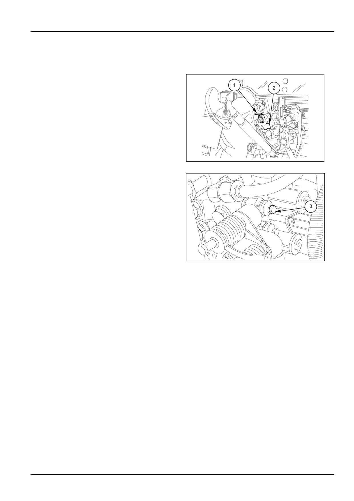
The front lift works with the transmission oil. It is operated
by one of the rear mount remote valves illustrated in the
figure.
NOTE: If hydraulic stabilizer struts are installed, the lift
can be connected to the distributor (1) or (2). Check that
the distributor for actuating the lift has the float function.
MOIL13TR00955AA
1
With the lift connected, loosen the screw (3) on the control
valve to go into single-acting operation.
MOIL13TR00951AA
2
6-25
6 - WORKING OPERATIONS
Operation
Version with mechanically controls lift
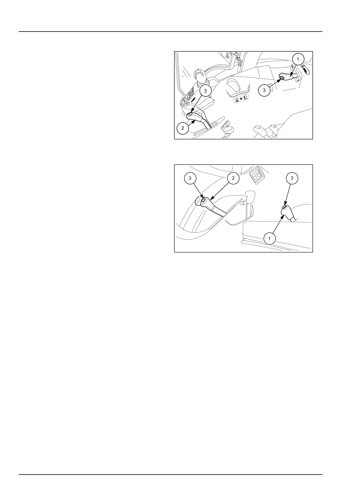
The lift works in position control. It is operated with one of
the two levers (1) or (2) that command the rear distributors
with the "DIVERTER" function, that is to say by pressing
the button (3). The levers and distributors are marked with
the same colour to facilitate identification.
Press the button (3) and move the lever of the same colour
in which the connection was made forwards to lower or
backwards to lift the implements connected to the front
lift.
NOTE: On release, the levers automatically return to the
central position. If it is necessary to work with the lift in
the float position, move the levers beyond the stop where
MOIL13TR01424AA
3
they are held by a special catch (detent). From the float
position, to be able to lift the implement the levers must
Version with electronically controls lift
be manually unhooked.
NOTICE: When working with implements connected to
the lift, pay attention to the operations as they increase
the dimensions of the machine.
MOIL13TR01003AA
4
6-26
6 - WORKING OPERATIONS
Hydraulic lift with electronic control
WARNING
Crushing hazard!
The lifting systems must be operated by qualified personnel who are aware of the correct procedures
to follow. Make sure all lifting equipment is in good condition, and all hooks are equipped with safety
latches.
Failure to comply could result in death or serious injury.
W0256A
The functions of the front lift are controlled by the same ECU as the rear lift.
For reasons of safety, the front lift controls are disabled when the tractor is started.
The disabled status is signalled by the indicator light
on the instrument cluster coming on.
Enabling controls
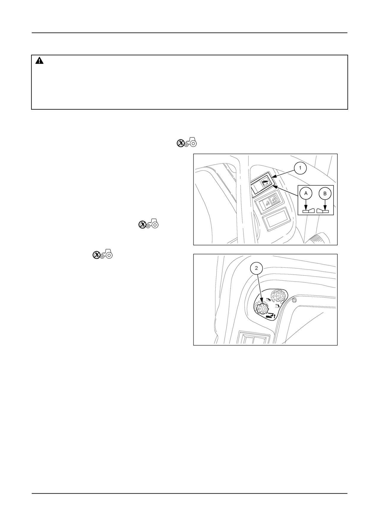
To enable the controls, proceed as follows:
• With the engine running, check that the alternator
charging light is OFF;
• Set the switch (1) first to the raising position (B) and
then to the lowering position (A);
• Turn the work position potentiometer (2) clockwise,
then anticlockwise until the indicator
goes out.
NOTE: Should a fault occur on the lift after malfunction-
ing of the sensors/actuators, the control unit will send a
MOIL13TR00953AA
1
signal to the indicator
. The type of flash enables
identifying the fault code and the corresponding problem.
MOIL13TR00954AA
2
6-27
6 - WORKING OPERATIONS
Controls
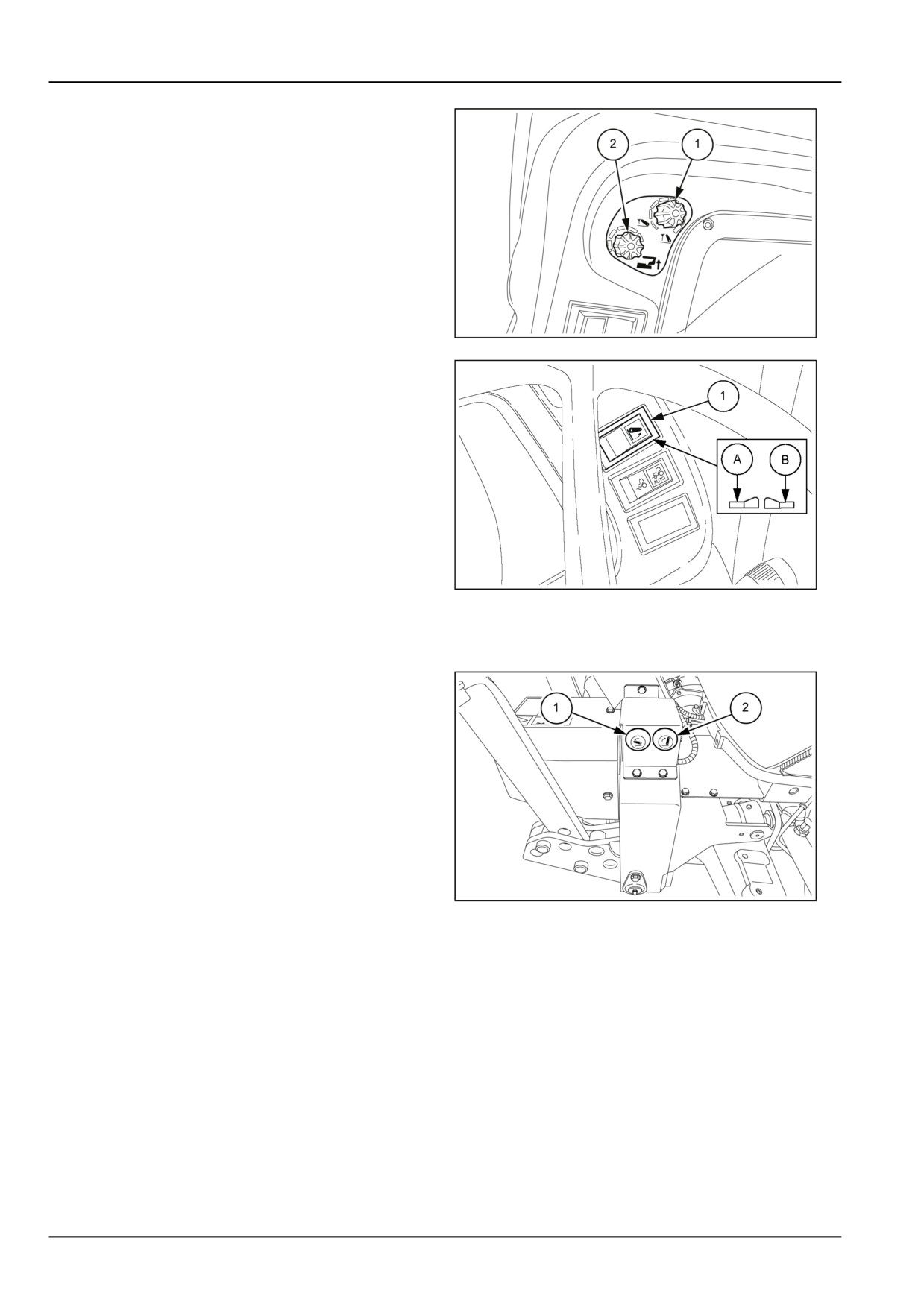
The two potentiometers (1) and (2) fig.
3, situated on
the left-hand side of the dashboard (instrument cluster),
enable regulating the lifting limit and the work position.
The switch (1) fig. 4, on the right-hand side, enables lifting
and lowering the implement.
Knob to adjust arm lift limit;
• Turn the knob (1) fully clockwise to raise the lift arms up
to the limit of the lift travel;
MOIL13TR00796AA
3
• Turn the knob (1) anticlockwise to reduce the arm lift
travel gradually until it is eliminated.
Working position adjustment knob;
• Turn the knob (2) fully clockwise, for the minimum work-
ing depth;
• Turn the knob (2) anticlockwise, to progressively in-
crease the working depth.
Raise/lower switch
To raise and lower the implement, use the switch (1) fig.
4, which has two positions:
MOIL13TR00953AA
4
• Position (A) , lowers
• Position (B) , lifts
External lift and lower controls
The two external lift control buttons enable connecting
and unhooking the implement from the lift arms.
1. Arms down control button.
The lift arms are made to lower by holding down the
button (1). The lowering phase ends at the moment
when the button is released.
2. Arms up control button.
The lift arms are made to lift by holding down the button
(2). The lifting phase ends at the moment when the
button is released.
MOIL13TR00345AA
5
NOTE: If the external lift control buttons are used, the
internal controls are disabled.
NOTICE: When the external controls (1) and (2) are used,
do not stand between the tractor and the implement.
6-28
6 - WORKING OPERATIONS
REAR 3-POINT HITCH
Operating Instructions
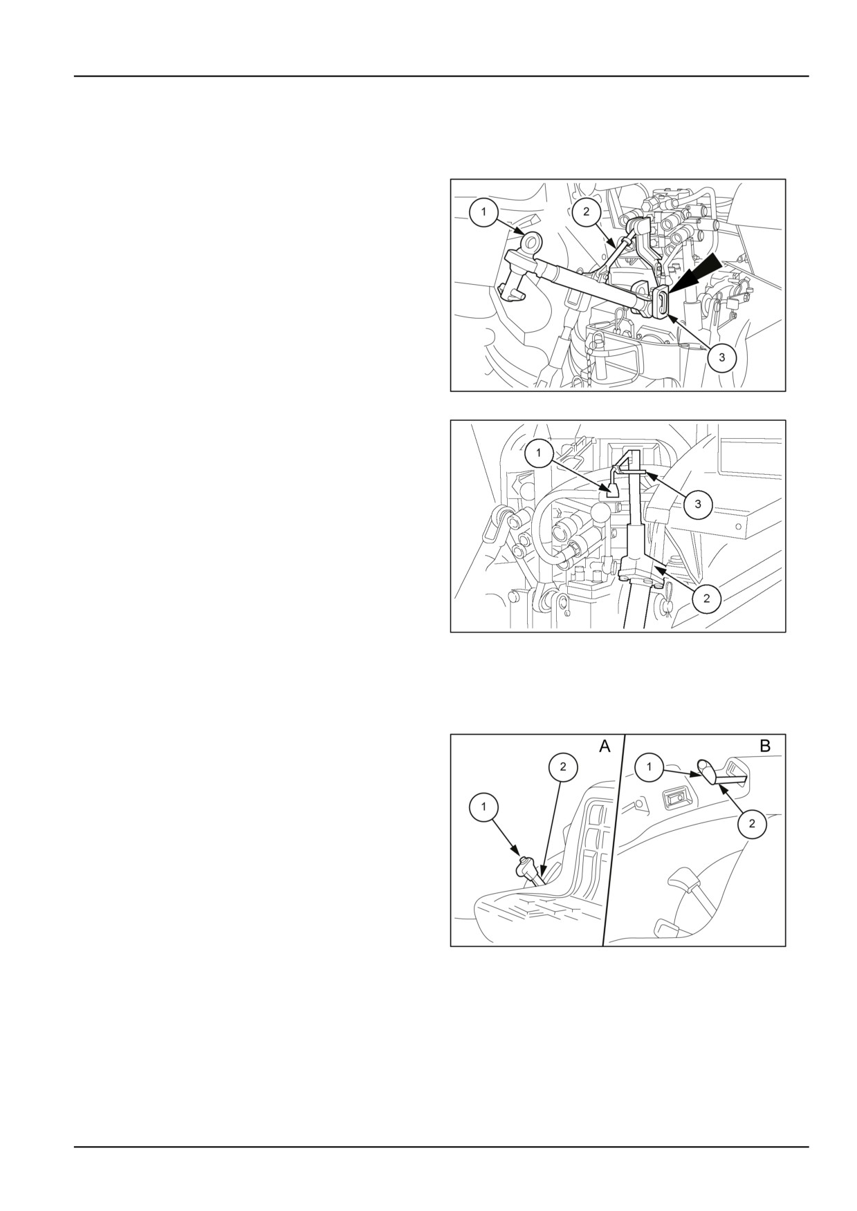
Adjustable top link
The top link (1) can be connected to the support bracket
by means of the two holes. Select the most suitable hole
for attaching the implement.
NOTE: When inserting the top link pivot pin (3) position it
so that the safety pin enters in its safety hole as shown in
the figure.
MOIL13TR00822AA
1
Standard left-hand lift rod
Adjust the length of the lift rod by screwing the end in or
out
NOTE: When using the tractor without implements, al-
ways fit the spacer spring to prevent the arms from touch-
ing the tyres.
Right-hand lift rod with crank adjustment
The right-hand lift rod (2) fig. 2 can be adjusted by means
of a crank (1) that can also be operated from the driving
position.
MOIL13TR00824AA
2
NOTICE: After adjusting the rod, lock the lever (1) with
the catch (3) to prevent the lever (1) from coming into
contact with parts of the machine or the adjustment getting
changed due to vibration.
Hydraulic adjustment of the right-hand verti-
cal rod (on request)
The right-hand vertical rod can be adjusted hydraulically
with the lever (2), that can be positioned on the right-hand
side next to the driver's seat if the tractor is equipped with
an electronically controlled lift (detail A) vice versa, if the
tractor is equipped with a mechanically controlled lift, the
rod adjustment lever will be positioned on the right-hand
rear side (detail B). To adjust the rod, hold down pushbut-
ton (1) and gradually move the lever (2).
MOIL13TR00826AA
3
6-29
6 - WORKING OPERATIONS
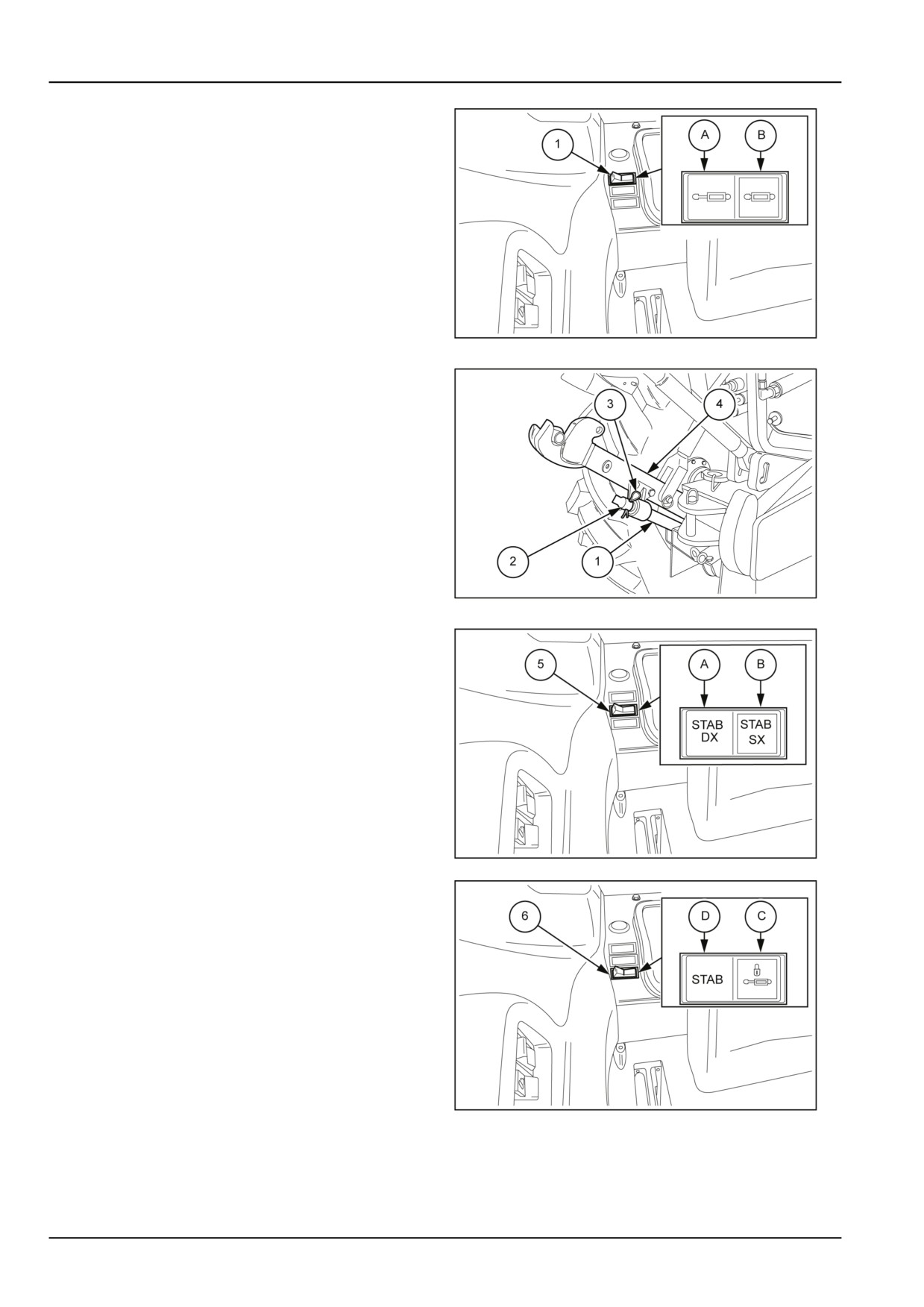
Hydraulic adjustment of the right-hand lift
rod (on request)
The right-hand lift rod (2) fig. 2 is available with hydraulic
adjustment using the specific switch
• Press the switch (1) into position (A) to raise the rod;
• Press the switch (1) into position (B) to lower the rod.
MOIL13TR00827AA
4
Standard side stabiliser struts
To adjust the length of the struts (3) remove the cotter pin
(2) and rotate the coupling (1) of 90 ° for fast changes or
screw in or out for limited changes. Always reinsert the
cotter pin after adjusting the struts.
MOIL13TR00829AA
5
Side stabiliser struts with hydraulic adjust-
ment (optional)
The struts are adjustable with the switches (5) and (6). To
regulate the two lift arms, proceed as follows:
To regulate the swing of the struts, use the button (5)
• Press the button into position (A) to operate the right-
hand stabiliser strut;
• Press the button into position (B) to operate the left-
hand stabiliser strut.
On completing the adjustment, to lock the struts in the
MOIL13TR00832AA
6
determined position and completely cancel the swing of
the lower arms (4) fig.
5, press switch (6) into position
(C). To unlock the struts and keep the lower arm (4) free
to swing, press the button (6) into position (D).
NOTICE: With the switch (6) in the locked position (C), do
not operate the button (5) to regulate the struts. When the
lower arms need to be varied (4), the switch (6) must be
turned off and returned to the unlock position (D).
MOIL13TR00834AA
7
6-30
6 - WORKING OPERATIONS
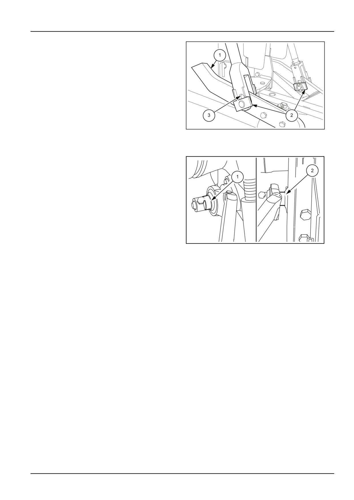
Adjust the lateral stabiliser struts (1) fig.
5, so that the
lateral movement of the lower arms (1) does not exceed
12 cm (4.72 in)12 cm per side.
It is possible to set the float mode of the lower lift arms
(1) by rotating the pins (2) into a vertical position, so as to
allow them to swing freely inside the slots (3).
MOIL13TR00835AA
8
Lower arm mounting position
For light work
When operating the tractor in draft or mixed control, fit
the lower arms (1) fig.
8 with spacers (2) fitted inside
the arms for greater lift sensitivity when working with light
equipment.
Normal or heavy work
When operating the tractor in draft or mixed control, fit the
spacers (1) outside the lower arms for normal or heavy
work. This position, which reduces lift sensitivity, enables
improved tractor use.
MOIL13TR01004AA
9
6-31
6 - WORKING OPERATIONS
Converting from 1st to 2nd category
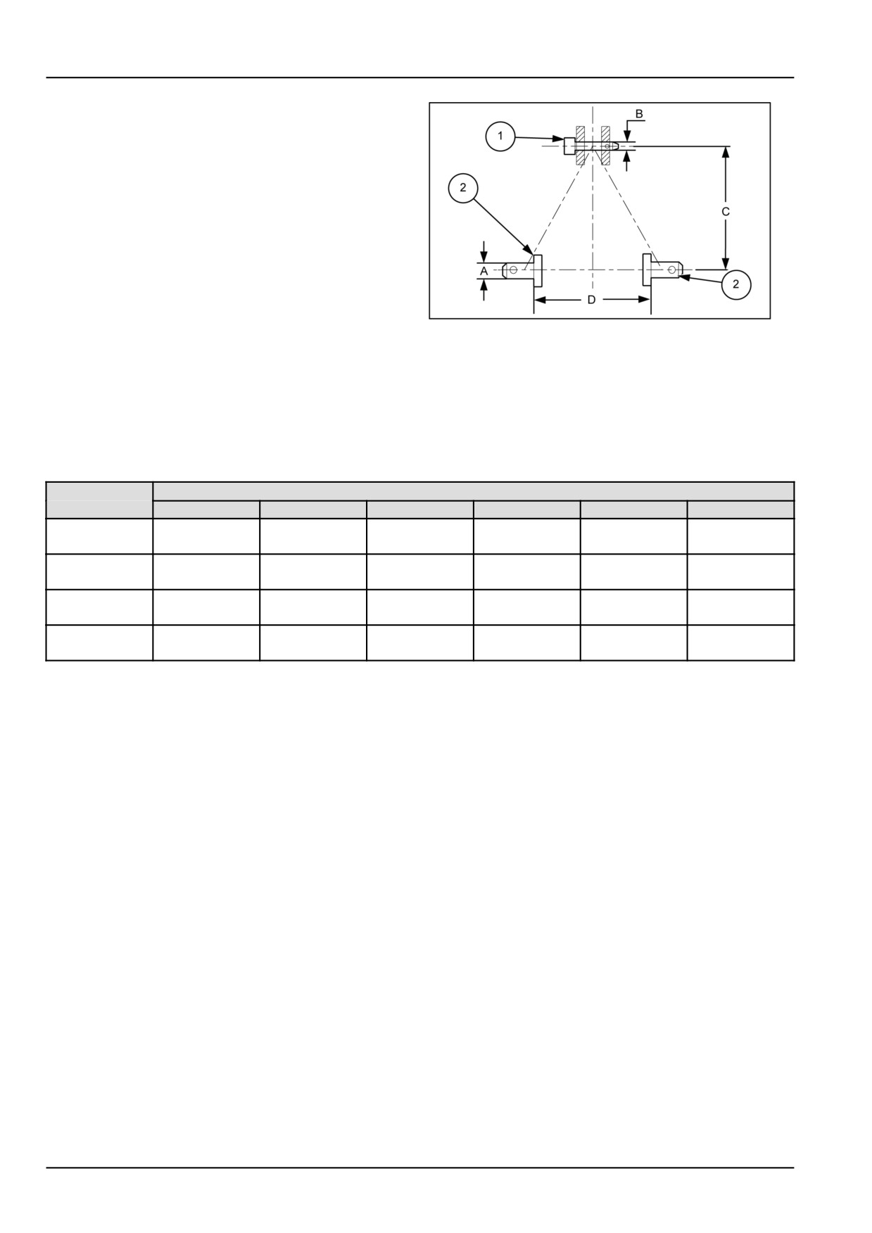
To allow both 1st and 2nd category equipment to be used,
the three-point linkage has:
• abushwithaninsidediameterof19 mm(0.75 in)(1)for
1st category implements, to be inserted in the spherical
bushing at the end of the top link;
• a set of bushes with an inside diameter of 22 mm
(0.87 in) (2) for 1st category implements, to be inserted
in the spherical bushings at the ends of the lower lift
arms.
The three-point linkage system enables connecting both
MOIL13TR00613AA
10
first and second category implements.
Depending on the category of the implement, it is recom-
mended to respect the dimensions (C) and (D) given in
the table below in order not to damage the coupler.
1. Top link pin
2. Lower lift arm pins
Categories
Dimensions
1N
1
2
2N
3N
3
36.6 mm
36.6 mm
A
22 mm (0.9 in)
22 mm (0.9 in)
28 mm (1.1 in)
28 mm (1.1 in)
(1.4 in)
(1.4 in)
25.5 mm
25.5 mm
31.75 mm
31.75 mm
B
19 mm (0.7 in)
19 mm (0.7 in)
(1.0 in)
(1.0 in)
(1.2 in)
(1.2 in)
360 mm
460 mm
610 mm
610 mm
685 mm
685 mm
C
(14.2 in)
(18.1 in)
(24.0 in)
(24.0 in)
(27.0 in)
(27.0 in)
400 mm
683 mm
825 mm
683 mm
825 mm
965 mm
D
(15.7 in)
(26.9 in)
(32.5 in)
(26.9 in)
(32.5 in)
(38.0 in)
6-32
6 - WORKING OPERATIONS
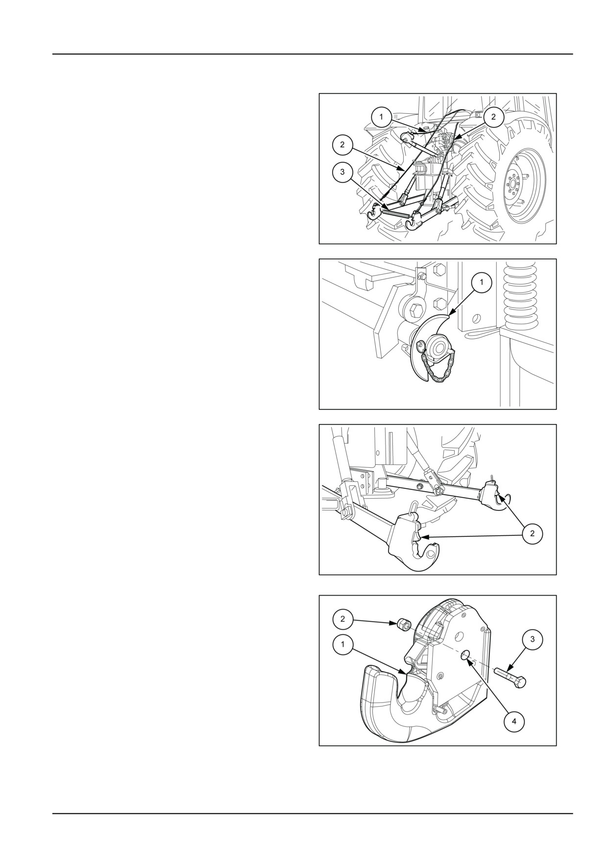
Attach the implement
With the lower arms fully lowered, adjust the length of
the control cables (2), so that they do not drag on the
ground when attached to the tractor. Correctly adjust the
distance between the lower arm hook ends by tightening
or loosening the spacer spring rod (3).
Fit the conical pick--up profiles (1) fig. 2 on the implement
hitch pins, as shown in the figure.
Move the tractor forward, in position in relation to the im-
plement, then raise the lower arms: the implement will be
hitched automatically. The hook ends (2) fig.
3 should
engage in the locked position. If using 1st. category im-
plements, fit the reducer bushes on the implement hitch
pins.
DCUTLNEIT046S6A
1
NOTICE: Before lifting the implement, make sure that the
two hook ends (2) fig. 3 have engaged in the locked po-
sition.
Release the end of the top link by pulling back the control
cable (1) fig. 1 and hook onto the implement.
Adjust the length of the top link by tightening or loosening
the threaded sleeve.
DCUTLNEIT045S6A
2
DCUTLNEIT047S6A
3
NOTICE: The quick couplers are fitted to be able to be
locked so as to prevent the implement from accidentally
getting unhooked.
To prevent the implement from getting unhooked it is rec-
ommended to secure the catches (1) in the locked position
when using heavy overhanging implements (for instance,
grass cutters, inter--row hoeing machines that come out-
side the tractor clearance) or when travelling on public
roads.
To lock the catches (1), insert a screw (3) into the hole
(4) and lock it with a self--locking nut (2), available in any
hardware store.
DCUTLNEIT048S6A
4
6-33
6 - WORKING OPERATIONS
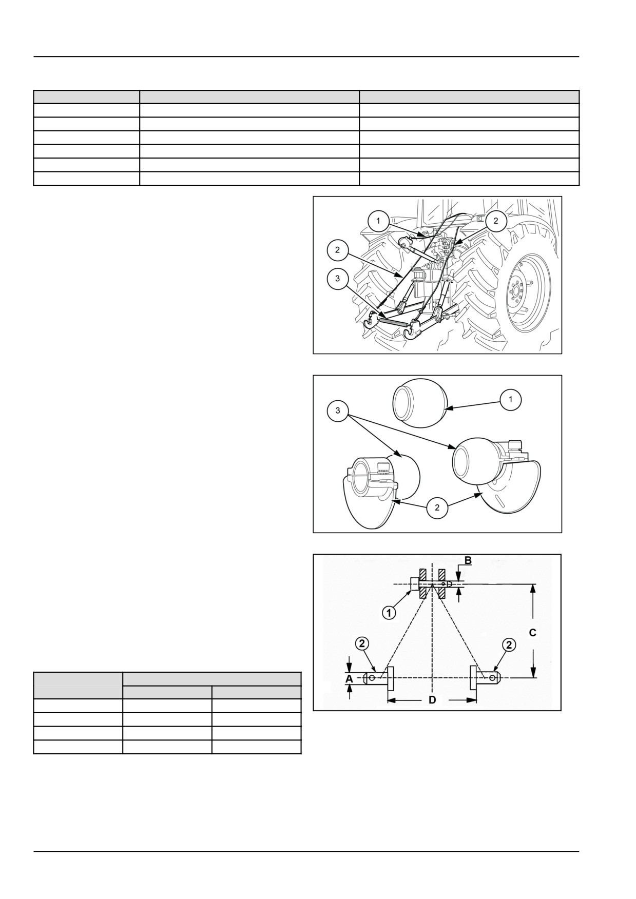
The type of screws and nuts suited to lock the catches (1) are given in the chart.
Cat. Hook
UNI 5737 screw cl. 8.8
UNI 7473 cl.6S nut
1
M6x40 opt. 7/32” x 1”1/2
M6 opt. 7/32”
2S
M6x45 opt. 7/32” x 1”3/4
M6 opt. 7/32”
2
M8x50 opt. 5/16” x 2”
M8 opt. 5/16”
3S
M8x55 opt. 5/16” x 2”1/8
M8 opt. 5/16”
3
M8x55 opt. 5/16” x 2”1/8
M8 opt. 5/16”
4
M8x65 opt. 5/16” x 2”1/2”
M8 opt. 5/16”
Removing Equipment
Rest the implement on the ground and make sure that it
is stable. Remove the safety screws (3) fig.
4 from the
two hooks to free the catches (1) fig. 4. While sitting in
the driving seat, pull the control cable (1) to unhook the
third point (3) fig.
5. Slightly raise the implement, then
release the hook ends by pulling the control cables (2) fig.
5 directly from the driving position. Lower the lower arms
until the hooks are released.
DCUTLNEIT046S6A
5
Tapered profiles
Three second category ball-bushings are supplied for in-
stallation on the implement, if required. The ball-bushing
with projecting lips (1) should be installed on the imple-
ment upper hitch pin. The two plain ball-bushings (3) with
their detachable guides (2) should be installed on the im-
plement lower hitch pins.
DCUTLNEIT043S6A
6
The three-point linkage system enables connecting sec-
ond category implements.
It is recommended to respect the dimensions (C) and (D)
given in the table below in order not to damage the cou-
pler.
1. Top link pin
2. Lower lift arm pins
Categories
Dimensions
2
2N
A
28 mm (1.1 in)
28 mm (1.1 in)
DCSPVEGB064S6A
7
B
25.5 mm (1.0 in)
25.5 mm (1.0 in)
C
610 mm (24.0 in)
610 mm (24.0 in)
D
825 mm (32.5 in)
683 mm (26.9 in)
6-34
6 - WORKING OPERATIONS
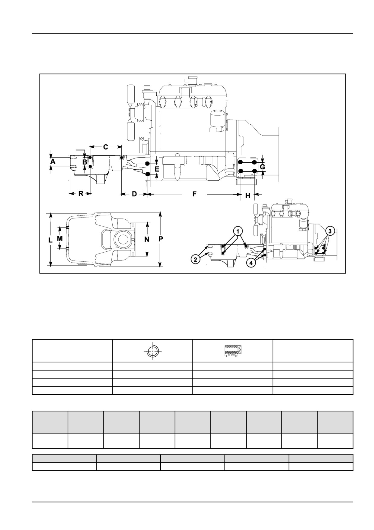
Additional equipment attachment points
Two-wheel drive (2WD)
DCSPFNEGB038S3F
1
The tractor is provided with threaded holes on both sides for connecting implement and auxiliary equipment. The
figure shows the free fixing holes on the left-hand side of the tractor, which are identical and symmetrical to the fixing
holes on the right-hand side.
NOTE: Use exclusively the holes specified in figure when mounting auxiliary equipment. The use of different holes for
auxiliary applications automatically exonerates the manufacturer from all liability in relation to damage to the tractor
or injury to persons, resulting from failure to observe the relative regulations.
Hole
Torque Specifications
1
M 12 x 1.25
24 mm (0.94 in)
350 - 400 N·m
2
M 20 x 2.5
36 mm (1.42 in)
400 - 450 N·m
3
M 20 x 2.5
35 mm (1.38 in)
400 - 450 N·m
4
M 20 x 2.5
38 mm (1.50 in)
400 - 450 N·m
Dimension
F
F
A
B
C
D
E
T4.75F
T4.95F
G
H
T4.85F
T4.105F
75 mm
75 mm
250 mm
234.5 mm
70 mm
624 mm
711 mm
60 mm
80 mm
(2.95 in)
(2.95 in)
(9.84 in)
(9.23 in)
(2.76 in)
(24.57 in)
(27.99 in)
(2.36 in)
(3.15 in)
L
M
N
P
R
470 mm (18.50 in)
174 mm (6.85 in)
360 mm (14.17 in)
513 mm (20.20 in)
160 mm (6.30 in)
6-35
6 - WORKING OPERATIONS
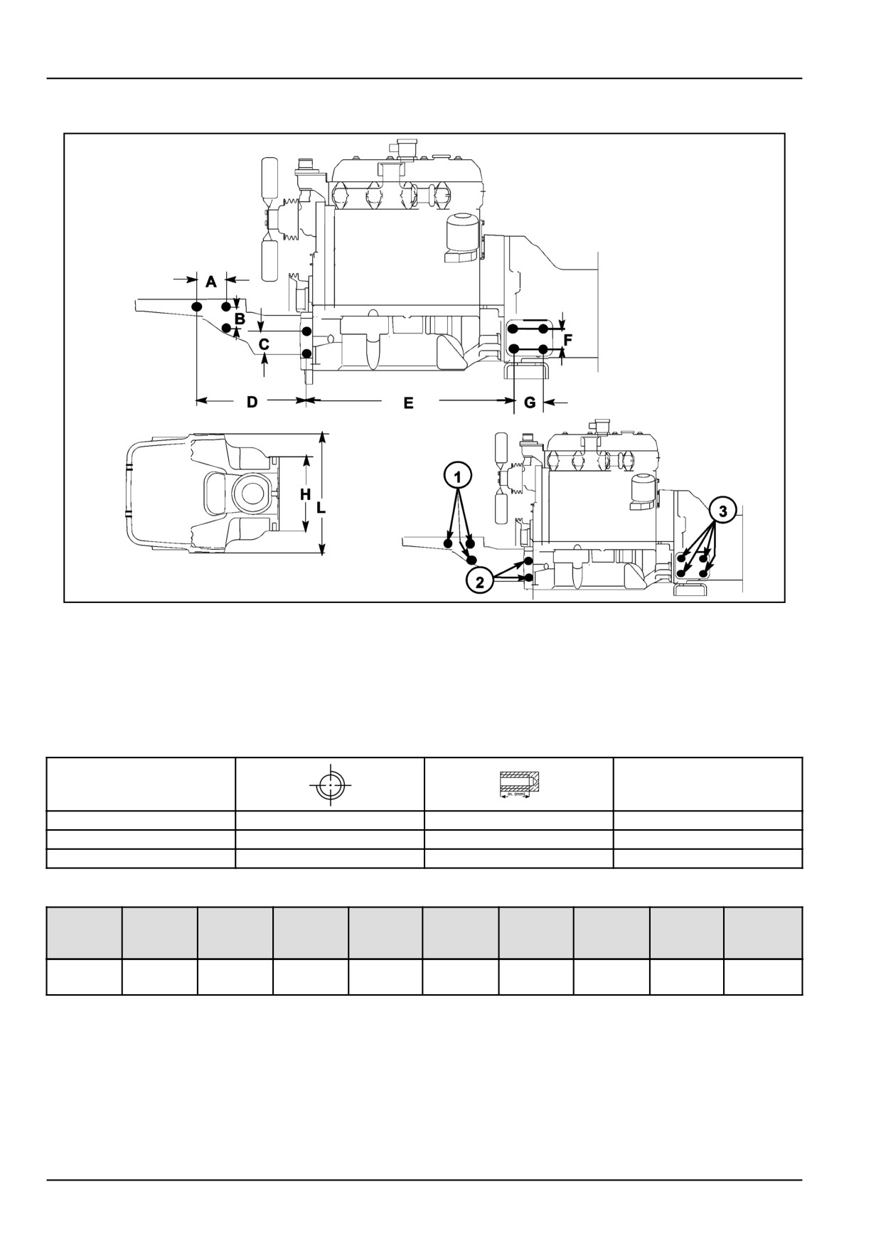
4WD MODELS (SUPERSTEER)
DCSPFNEGB039S3F
2
The tractor is provided with threaded holes on both sides for connecting implement and auxiliary equipment. The
figure shows the free fixing holes on the left-hand side of the tractor, which are identical and symmetrical to the fixing
holes on the right-hand side.
NOTE: Use exclusively the holes specified in figure when mounting auxiliary equipment. The use of different holes for
auxiliary applications automatically exonerates the manufacturer from all liability in relation to damage to the tractor
or injury to persons, resulting from failure to observe the relative regulations.
Hole
Torque Specifications
1
M 12 x 1.25
24 mm (0.94 in)
350 - 400 N·m
2
M 20 x 2.5
36 mm (1.42 in)
400 - 450 N·m
3
M 20 x 2.5
35 mm (1.38 in)
400 - 450 N·m
Dimension
E
E
A
B
C
D
T4.75F
T4.95F
F
G
H
L
T4.85F
T4.105F
95 mm
75 mm
70 mm
389.5 mm
622 mm
709 mm
60 mm
80 mm
360 mm
513 mm
(3.74 in)
(2.95 in)
(2.76 in)
(15.33 in)
(24.49 in)
(27.91 in)
(2.36 in)
(3.15 in)
(14.17 in)
(20.20 in)
6-36
6 - WORKING OPERATIONS
FRONT 3-POINT HITCH
Operating Instructions
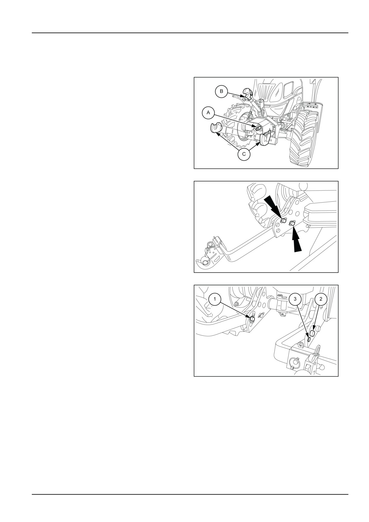
A Power take−off shaft
B Adjustable top link
C Lower lift arms
MOIL13TR00968AA
1
With no implements connected
It is advised to remove the horizontal arms when using the
tractor without front−hitched implements (to avoid knock-
ing into obstacles), or when on the public highway. To
remove the arms, remove the pins shown in the figure.
MOIL13TR00969AA
2
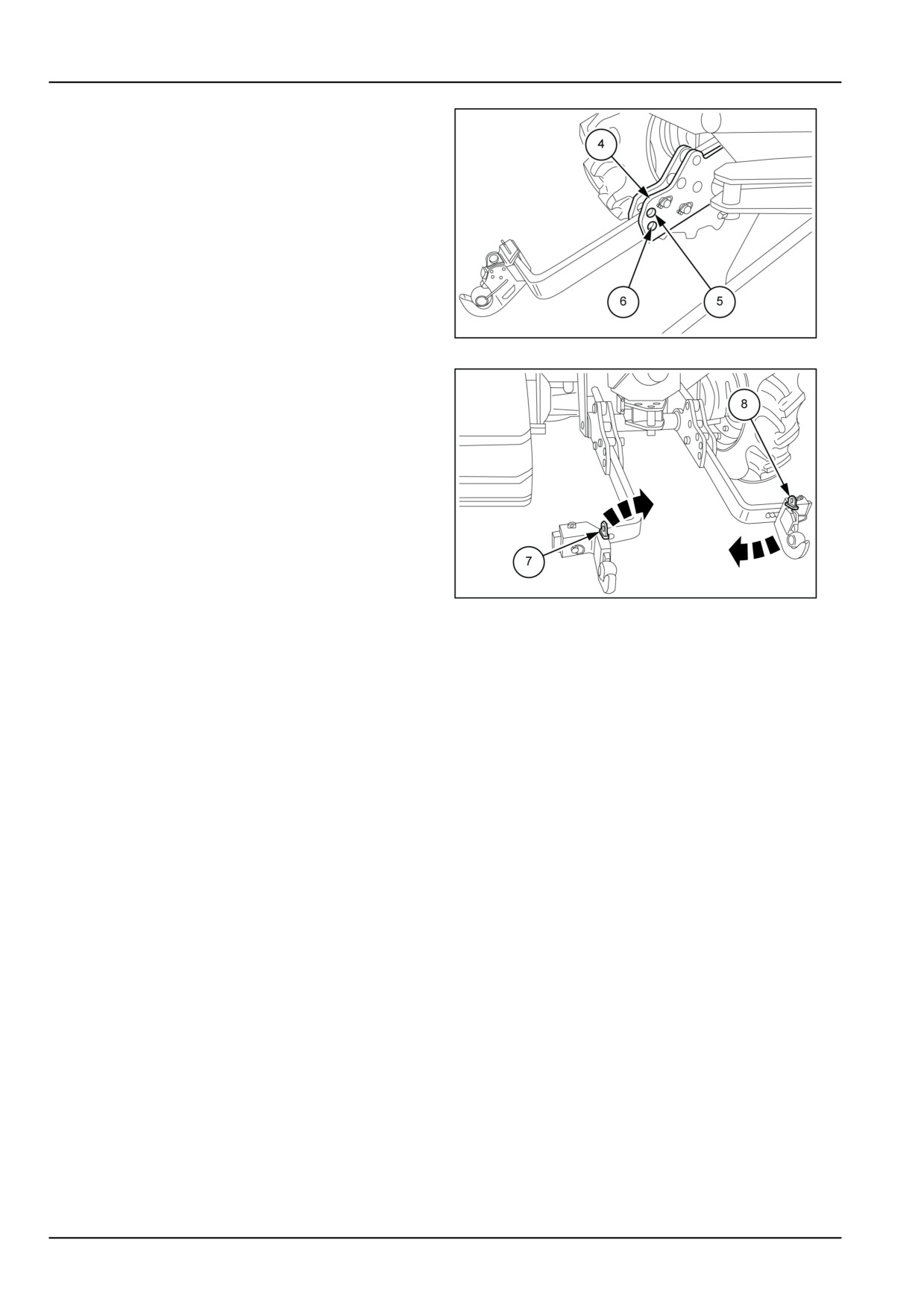
Horizontal arm mounting position
The horizontal arms are attached to the support in three
different positions:
First position
• Top position, with pin (2) securing the arms in the hole
(1) and hole (3) free. In this position the arms are at
their highest position off the ground.
Second position
• Bottom position, with the arm fixing pin in the hole (3)
and hole (1) free: In this position the arms are at their
MOIL13TR00970AA
3
lowest position off the ground.
6-37
6 - WORKING OPERATIONS
Third position
• Floating position with the lock pin inserted in the hole
(4) and the holes (5) and (6) free. In this position the
lifting arms are free to move vertically.
MOIL13TR00971AA
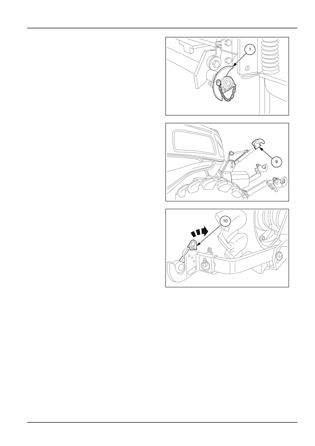
4
Positions for mounting the hook ends
The hook ends (7) and (8) slide and can be secured in
six different positions according to the width of the imple-
ment. The assembly shown in figure illustrates the three
narrowest positions that can be obtained.
You can obtain another three positions for implements of
a higher class by swapping over the position of the hooks
as shown by the arrows in figure.
MOIL13TR00972AA
5
Maximum lift capacity
With third point connected to top hole of top link attachment bracket and for the entire lifting stroke:
At link ends of horizontal lines
1275 kg (2810.9 lb)
With centre of gravity at 610 mm (24.0 in) from link ends
980 kg (2160.5 lb)
6-38
6 - WORKING OPERATIONS
Quick fit implement linkage
Fit the conical pick−up profiles (1) fig. 6 on the implement
hitch pins.
Move the tractor forward, in position in relation to the im-
plement, then raise the lower arms: the implement will be
hitched automatically.
If using 1st category implements, fit the reducer bushes
on the implement hitch pins.
NOTICE: Before lifting the implement, make sure that the
two hook ends (10) have engage in the locked position.
DCUTLNEIT045S6A
6
Release the end of the top link by pulling back the lever
(9) and hook onto the implement. Adjust the length of the
top link by tightening or loosening the threaded sleeve.
Unhitching the implement
Rest the implement on the ground and make sure that it is
stable. Unhook the top link by pulling back the unhooking
lever (9). Slightly raise the implement, then release the
lower hook ends by pulling the release lever (10).
MOIL13TR00973AA
7
MOIL13TR00974AA
8
6-39
6 - WORKING OPERATIONS
SWINGING DRAWBARS
Safety rules
WARNING
Collision hazard!
During road transport, the drawbar must be locked in the center position, and the implement must be
centered behind the tractor.
Failure to comply could result in death or serious injury.
W0324A
WARNING
Loss of control hazard!
Always attach or pull towed vehicles from the tractor drawbar.
Failure to comply could result in death or serious injury.
W1013A
WARNING
Rear upset hazard!
Use the correct location on the tractor when attaching equipment. Always use the drawbar for trailed
equipment. Always use the three point hitch for mounted or semi-mounted equipment. Do not use
the hitch as a drawbar.
Failure to comply could result in death or serious injury.
W0331A
CAUTION
Avoid injury!
Follow ALL of the precautions listed below.
Failure to comply could result in minor or moderate injury.
C0125A
The towing equipment should be selected on the basis of the type of trailer or implement to be towed and should
comply with current legislation.
• The ease of handling and driving safety of the tractor depend on correct towing adjustment.
• If the towing device is fitted high, the towing capacity is increased, but there is a risk that the tractor will tip back.
Therefore ensure that the trailer shaft is not at too great an upward angle.
• When using 4WD, the towing bracket should be in the lower position with the shaft almost horizontal.
• Avoid towing excessively heavy trailers or loads.
• Never start suddenly, as this also considerably increases the risk of tipping backwards.
• Always brake the trailer first and then the tractor.
6-40
6 - WORKING OPERATIONS
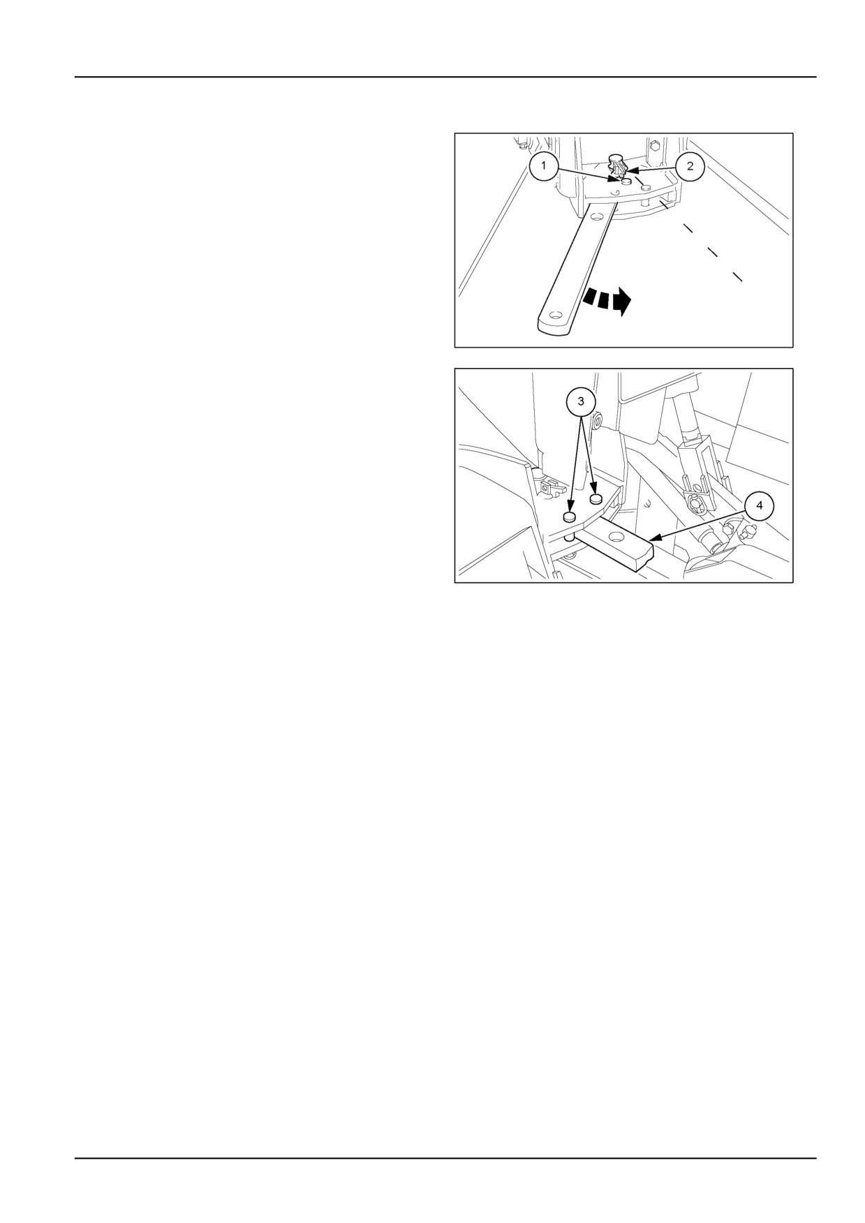
Swinging drawbar
Use the swinging drawbar for implements, agricultural
machinery and trailers with two axles.
Do not use for single−axle trailers as they apply
excessive weight to the bar, which will risk tipping the
tractor.
The device can be supplied:
• with the relative brackets to fit rigid towing hooks and
towing hooks;
• with a bracket designed to fit only to a towbar.
The following adjustments can be made to the bar:
• Prevention of lateral swing by inserting two pins (3) in
the respective holes.
MOIL13TR00757AA
1
• Lateral adjustment of the bar, which can be positioned
either to the right or to the left by means of the pin (1), is
extremely useful for implements or machines requiring
free lateral movement.
• By varying the position of the locking pin (2) in the holes
of the drawbar (4) it is possible to vary the distance of
the tow from the PTO shaft.
NOTE: Use the front towing fork for possible emergency
trailer manoeuvres or for towing the tractor.
MOIL13TR01005AA
2
6-41
6 - WORKING OPERATIONS
WHEELS AND TIRES
Wheels and tires
WARNING
Explosion hazard!
Tires must be replaced by skilled personnel with the proper tools and technical knowledge. Unskilled
personnel replacing wheels or tires could result in serious physical injuries, tire damage, and/or wheel
distortion. Always have a qualified tire mechanic service wheels and tires.
Failure to comply could result in death or serious injury.
W0171A
WARNING
Explosion hazard!
A tire can explode during inflation. Replace a tire if it has any defect(s). Replace a wheel rim that has
cracks, wear, or severe rust.
Failure to comply could result in death or serious injury.
W0455A
USE, MAINTENANCE AND REPLACEMENT
• When changing tires, select suitable tires for the actual tractor use, taking account of the recommended combina-
tions.
• Do not exceed the permitted load indicated on the tires.
• Do not exceed the speeds shown on the tires, as this both overheats and causes premature tire wear.
• Do not fit used tires where their previous use is unknown.
• Ask the manufacturer or a tire specialist for advice.
• After fitting tires, check that the wheel nuts are tight after 3 hours in operation and then periodically.
• Following this, check the tightness on a regular basis.
• Do not stand tires on hydrocarbons (oil, diesel, grease, etc.).
• The tires fitted on the tractor must be checked periodically, with special care given to:
- tread, must have regular consumption;
- flanks, must not have any cracks, swellings or abrasions.
• Have the tires checked by a specialist if one or more of the problems mentioned above should occur.
• Consult an expert if a tire is subject to violent shocks, even if there are no visible signs of damage.
• Tires age, even if used infrequently or not at all.
• Cracks on the walls, sometimes accompanied by bulges, are a sign of ageing.
• Tires fitted on tractors which are not used for extended periods tend to age more rapidly than those used more
frequently. In this event, it is advisable to raise the tractor from the ground and protect the tires from direct sunlight.
6-42
6 - WORKING OPERATIONS
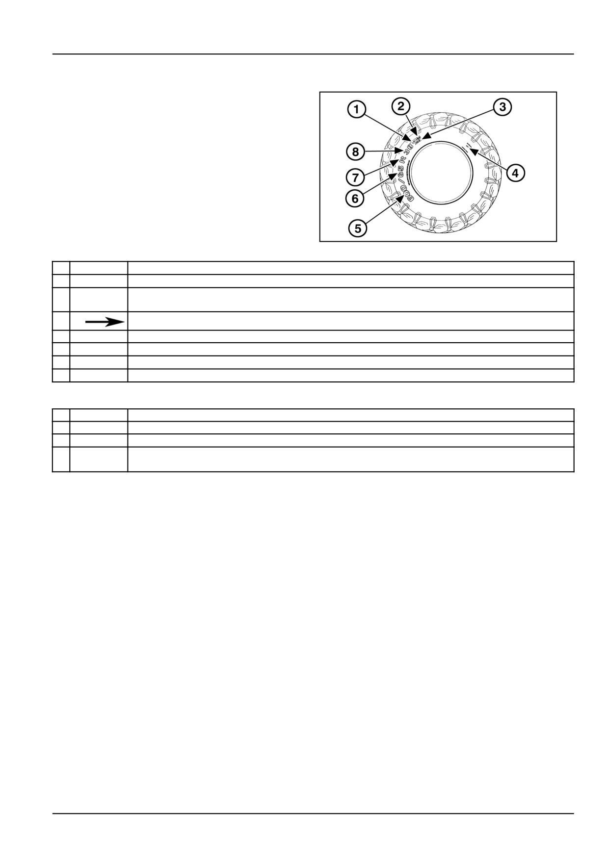
Tire marking
To indicate, dimensions, structure and specifications
of use of a tire, the manufacturers have internationally
adopted standard abbreviations and numbers. The draw-
ing shows an example of the marking on a tire used for
agricultural work. Example of reading the abbreviation
600/65 R 38.
DCUTDNEGB076S3A
1
1
157 154
Load capacity index.
2
A8 B
Speed code. Maximum speed in relation to load corresponding to load index (IC) see page
3
TUBE-
Tubeless tires. Tires with inner tubes are marked TUBE TYPE or left blank.
LESS
4
The arrow shows the direction of tire travel.
5
600
Nominal cross-section width in mm.
6
65
Ratio between height and width of cross-section.
7
R
Indicates the radial structure. On a conventional tire, the R is replaced by a hyphen (-).
8
38
Rim keying diameter.
Another example: 7.50-16 8 PR
1
7.50
Nominal width of cross-section in inches.
2
-
Conventional structure.
3
16
Rim keying diameter.
4
Resistance index of tire or number of ply that make up the tire. (This code is normally shown on
8 PR
conventional tires, whereas radial tires show the load capacity index).
6-43
6 - WORKING OPERATIONS
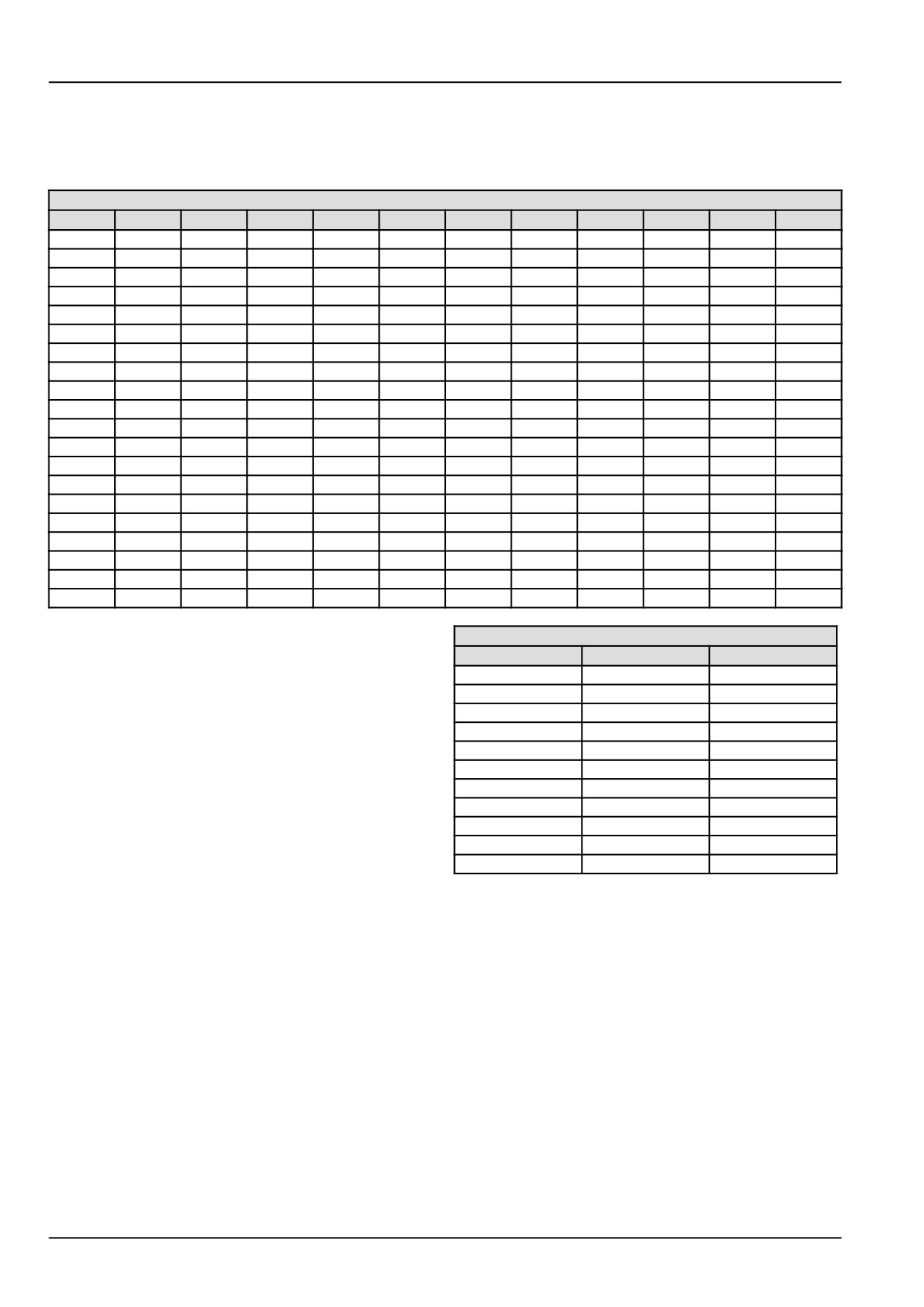
LOAD INDEX
The loading index (IC) is a numerical index indicating the maximum permissible load on the tire, for the speed indicated
by the relevant speed code, under the conditions specified by the manufacturer.
Loading index per wheel
IC
• kg
• lb.
IC
• kg
• lb.
IC
• kg
• lb.
IC
• kg
• lb.
100
800
1764
120
1400
3086
140
2500
5512
160
4500
9921
101
825
1819
121
1450
3197
141
2575
5677
161
4625
10196
102
850
1874
122
1500
3307
142
2650
5842
162
4750
10472
103
875
1929
123
1550
3417
143
2725
6008
163
4875
10748
104
900
1984
124
1600
3527
144
2800
6173
164
5000
11023
105
925
2039
125
1650
3638
145
2900
6393
165
5150
11354
106
950
2094
126
1700
3748
146
3000
6614
166
5300
11684
107
975
2150
127
1750
3858
147
3075
6779
167
5450
12015
108
1000
2205
128
1800
3968
148
3150
6945
168
5600
12346
109
1030
2271
129
1850
4079
149
3250
7165
169
5800
12787
110
1060
2337
130
1900
4189
150
3350
7385
170
6000
13228
111
1090
2403
131
1950
4299
151
3450
7606
171
6150
13558
112
1120
2469
132
2000
4409
152
3550
7826
172
6300
13889
113
1150
2535
133
2060
4542
153
3650
8047
173
6500
14330
114
1180
2601
134
2120
4674
154
3750
8267
174
6700
14771
115
1215
2679
135
2180
4806
155
3875
8543
175
6900
15212
116
1250
2756
136
2240
4938
156
4000
8818
176
7100
15653
117
1285
2833
137
2300
5071
157
4125
9094
177
7300
16094
118
1320
2910
138
2360
5203
158
4250
9370
178
7500
16535
119
1360
2998
139
2430
5357
159
4375
9645
179
7750
17086
Speed codes
SPEED CODE
SYMBOL
• km/h
• mph
The speed code indicates the speed at which the tire can
A1
5
3.10
transport a load corresponding to its loading index, under
A2
10
6.21
the conditions specified by the manufacturer:
A3
15
9.32
A4
20
12.42
NOTICE: Respecting the limits in the tables will ensure
A5
25
15.53
that the tires both perform well and are long-lasting. Over-
A6
30
18.64
loading tires substantially reduces their service life.
A7
35
21.74
NOTE: The values in these tables are also marked on the
A8
40
24.85
walls of the tires themselves.
B
50
31.06
C
60
37.28
D
65
40.38
6-44
6 - WORKING OPERATIONS
INFLATION PRESSURES
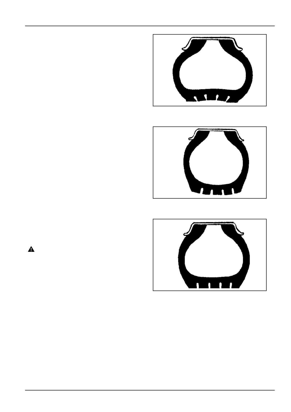
For safe and long-lasting tire use, the following
instructions must be closely observed.
• Use the correct pressures for each axle and for the type
of use planned.
• Ensure tire pressures are not lower than the correct val-
ues, to prevent overheating of the tires, which can lead
to:
- tire bursting;
- coming off rim;
- internal damage;
- irregular wear and short service life.
DCUTDNEGB077S3A
2
Low pressure
• Do not over-inflate the tires, as this may lead to damage
in the event of impact and, in extreme conditions, the
tire rim may be deformed or the tire may burst.
• Check tire pressures at least every two weeks, espe-
cially when liquid ballast is used. Tire pressures should
be checked only when the tires are cold, as pressures
rise during use, as a result of the tires heating up. Tires
can be assumed to be cold if they have not been used
for at least one hour, or have not covered more than two
to three kilometres. Never reduce tire pressures when
the tires are hot.
DCUTDNEGB078S3A
3
Pressure too high
When checking tire pressures, keep the body away from
the valve mechanism or cap.
NOTICE: The tire pressures vary depending on the load
weighing on the axles.
WARNING
Explosion hazard!
Always maintain correct tire pressure as in-
dicated in this manual. DO NOT inflate tires
above the recommended pressure. Excessive
pressure could result in tire failure.
Failure to comply could result in death or se-
rious injury.
W0109A
DCUTDNEGB079S3A
4
Correct pressure
6-45

6 - WORKING OPERATIONS
Tyre dimensions
2WD FRONT TIRES
Tires
Code
Index radius
Rim
6.50 - 16
8PR
360
4.50E x 16
7.00 - 12
6PR
—
4.25 x 12
7.50 - 16
8PR
390
5.50F x 16
11L-15 F3
8PR
300
W8 x 15
4WD FRONT TIRES
Tires
Code
Index radius
Rim
7.50 R 18
A8
410
5.50F x 18
260/70 R 20
A8
410
W9 x 20
280/70 R 16
A8
390
W8 x 16
280/70 R 18
A8
410
W9 x 18
280/70 R 20
A8
425
W9 x 20
300/70 R20
A8
450
W9 x 20
320/70 R 20
A8
475
W9 x 20
10.5/80 - 18
10PR
525
W9 x 18
2WD/4WD REAR TIRES
Tires
Alternative tires
Code
Index radius
Rim
12.4 R 28
320/85 R 28
A8
600
W10 x 28
13.6 R 28
340/85 R 28
A8
625
W12 x 28
14.9 R 28
380/85 R 28
A8
650
W13 x 28
360/70 R 28
-
A8
600
W10 x 28
380/70 R 20
-
A8
525
W11 x 20
380/70 R 24
-
A8
575
W11 x 24
380/70 R 28
-
A8
625
W13 x 28
420/70 R 24
-
A8
600
W13 x 24
420/70 R 28
-
A8
650
W13 x 28
420/70 R 30
-
A8
675
DWW13x30
19.5L - 24
-
10PR
625
W16L x 24
6-46
6 - WORKING OPERATIONS
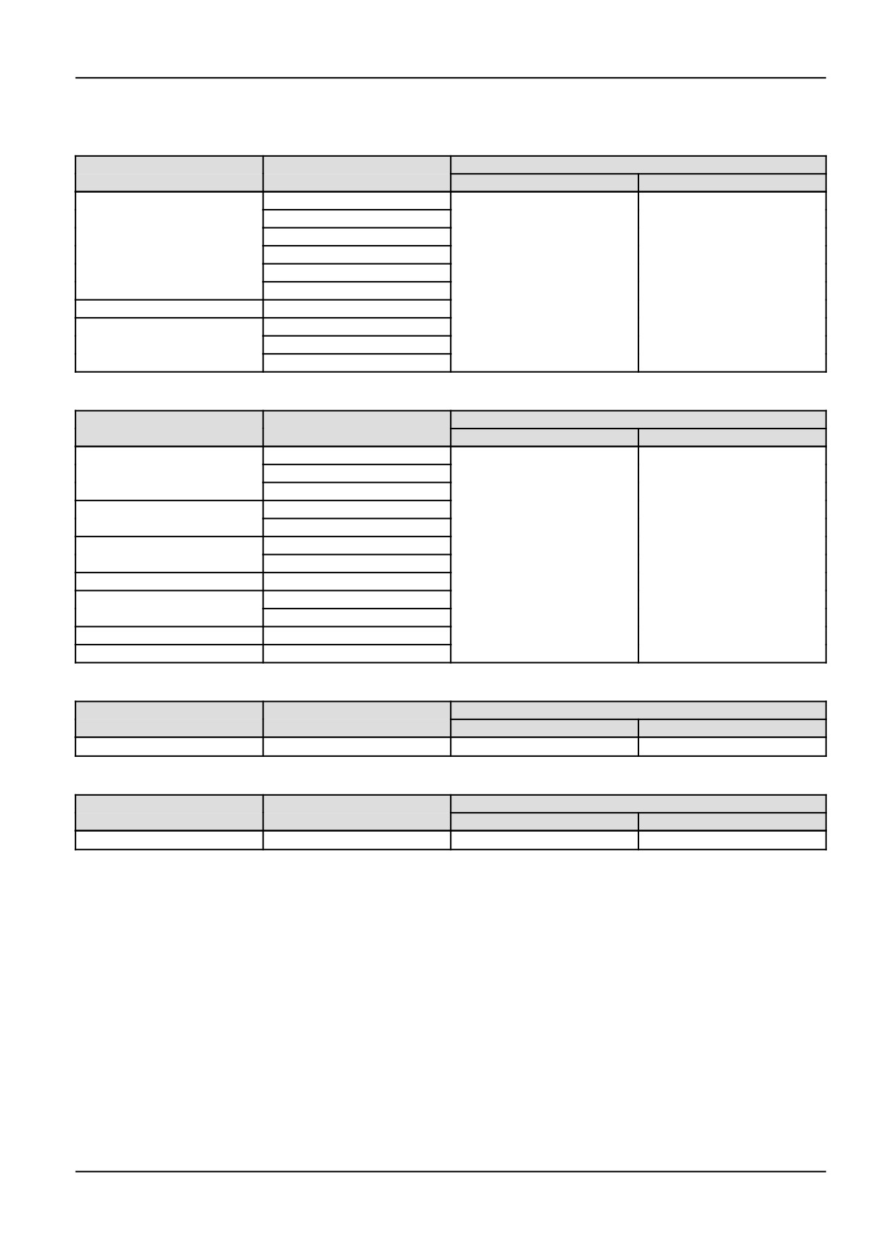
TIRE COMBINATIONS
RECOMMENDED COMBINATIONS FOR 2WD MODELS
Pressure bar
Front tires
Rear tires
Front
Rear
380/70 R 28
420/70 R 24
13.6 R 28 - 340/85 R 28
6.50 - 16
380/70 R 24
12.4 R 28 - 320/85 R 28
2.5 bar (36.3 psi)
1.5 bar (21.8 psi)
360/70 R 28
7.00 - 12
380/70 R 20
14.9 R 28 - 380/85 R 28
7.50 - 16
420/70 R 28
420/70 R 30
RECOMMENDED COMBINATIONS FOR 4WD MODELS
Pressure bar
Front tires
Rear tires
Front
Rear
13.6 R 28 340/85 R 28
7.50 R 18
12.4 R 28 - 320/85 R 28
360/70 R 28
13.6 R 28 - 340/85 R 28
260/70 R 20
380/70 R 28
380/70 R 20
280/70 R 16
1.5 bar (21.8 psi)
1.5 bar (21.8 psi)
380/70 R 24
280/70 R 18
420/70 R 24
14.9 R 28 - 380/85 R 28
280/70 R 20
420/70 R 28
300/70 R20
420/70 R 30
320/70 R 20
420/70 R 30
RECOMMENDED COMBINATIONS FOR 2WD MODELS - INDUSTRIAL TIRE
Pressure bar
Front tires
Rear tires
Front
Rear
11L-15 F3
19.5L - 24
2.5 bar (36.3 psi)
1.5 bar (21.8 psi)
RECOMMENDED COMBINATIONS FOR 4WD MODELS - INDUSTRIAL TIRE
Pressure bar
Front tires
Rear tires
Front
Rear
10.5/80 - 18
19.5L - 24
1.5 bar (21.8 psi)
1.5 bar (21.8 psi)
6-47
6 - WORKING OPERATIONS
WHEEL TRACK ADJUSTMENT
Wheel tread settings
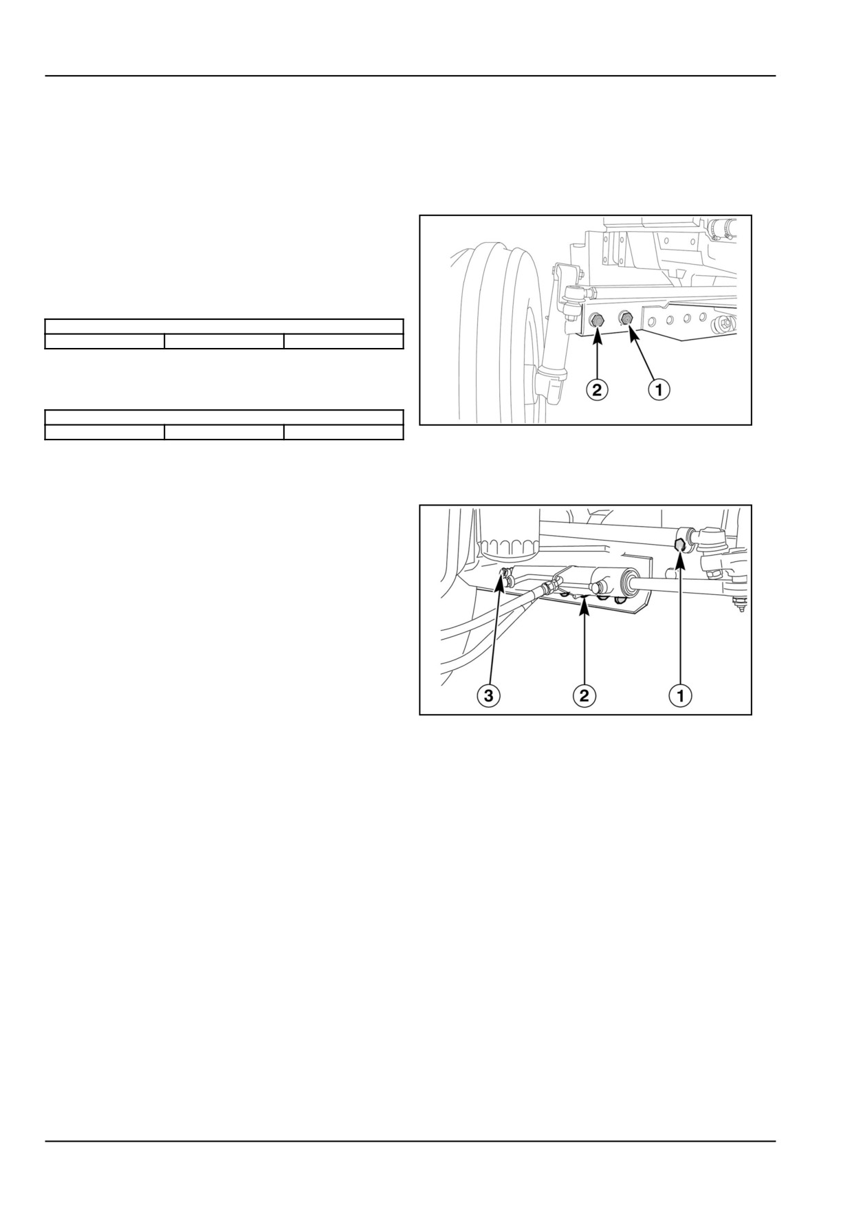
Front 2WD wheel track adjustment
To adjust the front wheel track, proceed as follows:
• Raise the front of the tractor using a jack positioned in
the middle of the axle;
• Release the sliding ends by loosening the two retention
screws (1) and (2) fig. 1on each side.
tightening torque
220 N·m
22.5 kgm
162.7 ftlbs.
• adjust the length of the steering struts connected to the
two wheels by loosening the fixing screws (1) fig. 2
tightening torque
39 N·m
4 kgm
29 ftlbs.
DCUTDNEGB062S3A
1
The possible wheel tracks are provided as shown on the
next page.
A further larger track width (maximum track) can be ob-
tained by reversing the wheels on their hubs.
Only use the maximum track when absolutely necessary.
NOTICE: As the tractor is fitted with hydrostatic steering,
proceed as described above for the left−hand wheel. For
the right−hand wheel, after having released the sliding
end of the axle the internal angle of the hydraulic cylinder
must be suitably adjusted. Proceed as follows:
• loosen the cylinder hose connectors
• make sure the screw (1) fig. 2 is loosened
• insert the pivot pin (3) fig.
2 in one of the four corre-
DCUTDNEGB063S3A
2
sponding holes (2) fig. 2;
• tighten the nut on the pin (3) fig.
2
(tightening torque
294 N·m − 30 kgm);
• tighten the screw (1) fig. 2 (tightening torque 39 N·m −
4 kgm);
• make sure that the hoses are not twisted and tighten
the connectors.
6-48
6 - WORKING OPERATIONS
Wheel track adjustment front 4WD and rear
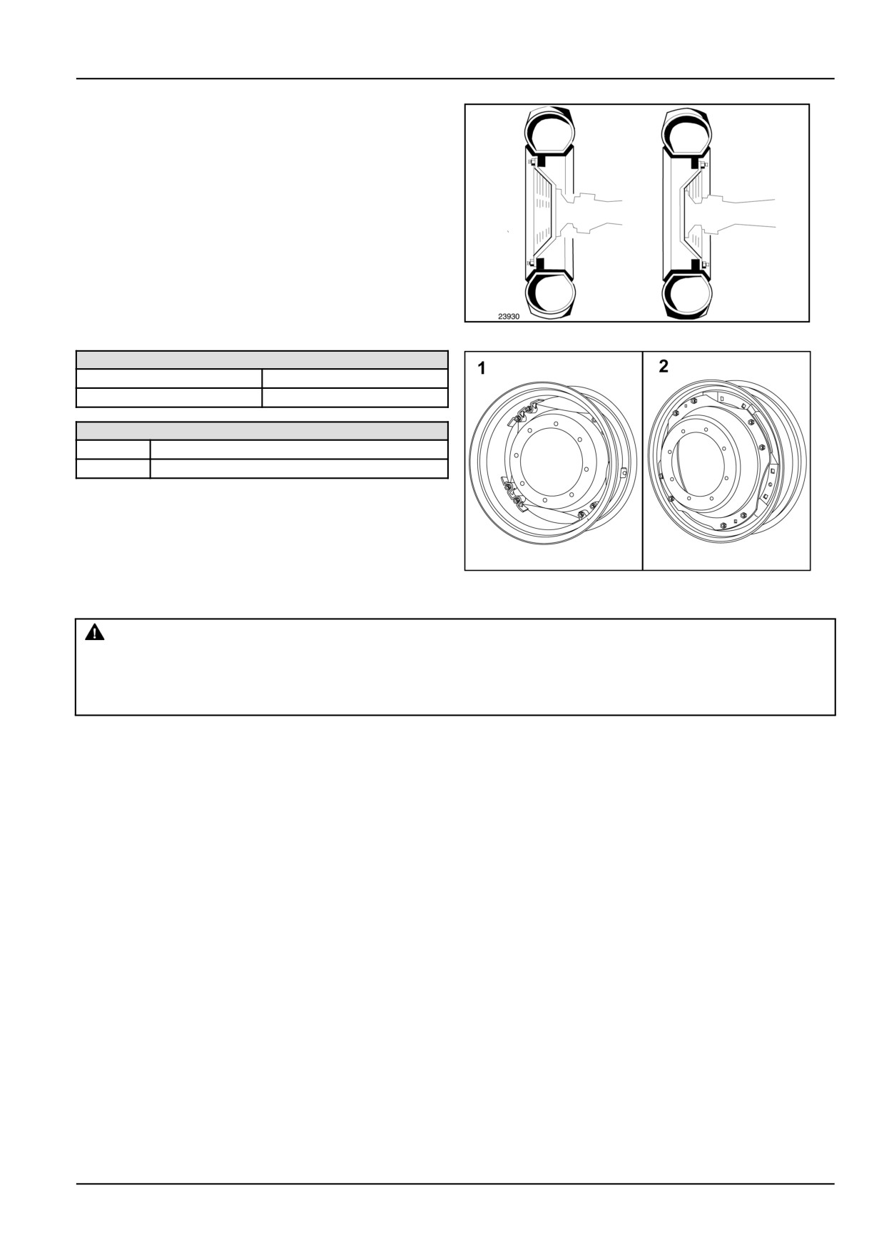
2/4WD
You can fit the wheel disk with the camber directed in-
wards or outwards.
Each of these two disk positions provides a different track
width, as shown on the following pages.
When adjusting the wheel track, ensure that the points of
the tire treads are still facing in the direction of forward
travel, indicated by an arrow on the tire walls.
Always check that the front and rear wheels are symmetri-
cally aligned in relation to the longitudinal axis of the trac-
tor.
DCAPLNEGB081S3A
3
Front and rear wheels
Front — M16
220 N·m (162.3 lb ft)
Rear — M18
310 N·m (228.6 lb ft)
Front and rear wheels
1
250 - 310 N·m (184.4 - 229 lb ft)
2
280 - 340 N·m (206.5 - 250.8 lb ft)
MOIL13TR00011AA
4
NOTICE: Select the appropriate rear track before changing the front track.
WARNING
Crushing hazard!
Wheel drive assemblies are heavy. Use an adequate lifting device. Reposition one side at a time.
Failure to comply could result in death or serious injury.
W0019B
6-49
6 - WORKING OPERATIONS
Steering angle adjustment
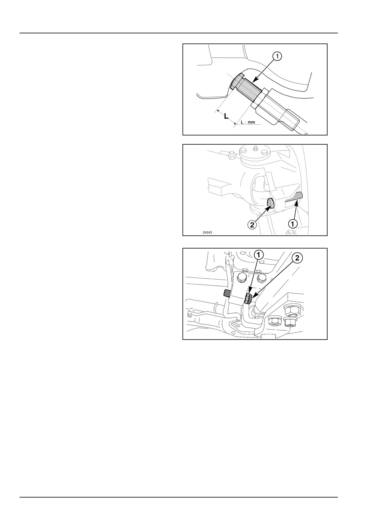
When using the narrowest tracks, the tires may touch the
tractor body when the steered wheels are at full lock and
the front axle is at maximum pivot position. To avoid this
problem, the steering angle can be adjusted by means of
screw (1) fig. 5.
To adjust the steering angle, proceed as follows:
• turn the wheels;
• adjust the protrusion (L) fig. 5 of screw (1) fig. 6 so that
the wheels cannot come into contact with the tractor
body;
DCUTDNEGB066S3A
5
• on termination of adjustment operations, secure the
screw (1) by means of the locknut (2) fig. 6.
Repeat the same operations for the opposite wheel.
NOTE: After adjusting the steering angle, make sure that
when the wheels are fully locked, there is at least a 20 mm
(0.79 in) clearance between the tire or the mudguard and
the tractor body.
DCUTDNEGB067S3A
6
Front axle swing adjustment
If necessary, you can increase the swing of the axle.
With the nut (1) fitted internally as in the figure, the axle
has its minimum swing.
To increase the swing, proceed as follows:
• Unscrew the screw (2) and move the nut (1) outwards.
NOTE: The same adjustments must be performed on the
opposite side.
NOTICE: When you are in the situation of greatest axle
DCSPNEGB039S3A
7
swing, adjust the steering angle so as to prevent the fully
steered wheels from interfering with the casing.
With the front lift fitted, keep the nut (1) fitted inside on the
least swing.
6-50
6 - WORKING OPERATIONS
Tire Combinations and Tread Positions
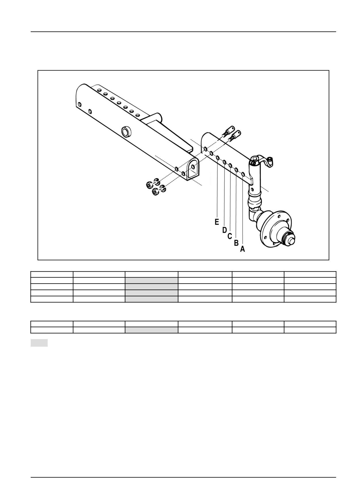
2WD FRONT WHEEL TRACKS
DCSPFNEGB060S3A
1
Tire
A
B
C
D
E
6.50 - 16
1146 mm (45.1 in)
1246 mm (49.1 in)
1346 mm (53.0 in)
1446 mm (56.9 in)
1546 mm (60.9 in)
7.00 - 12
1172 mm (46.1 in)
1272 mm (50.1 in)
1372 mm (54.0 in)
1472 mm (58.0 in)
1572 mm (61.9 in)
7.50 - 16
1165 mm (45.9 in)
1265 mm (49.8 in)
1365 mm (53.7 in)
1465 mm (57.7 in)
1565 mm (61.6 in)
11L-15 F3
1212 mm (47.7 in)
1312 mm (51.7 in)
1412 mm (55.6 in)
* 1512 mm (59.5 in)
* 1612 mm (63.5 in)
Or turning the wheel
Tire
A
B
C
D
E
11L-15 F3
1252 mm (49.3 in)
1352 mm (53.2 in)
1452 mm (57.2 in)
* 1552 mm (61.1 in)
* 1652 mm (65.0 in)
Rated wheel track setting
(*) Track settings to be made only on the field or on road with the maximum clearance lights extended.
NOTE: Tracks lower then rated setting could require: steering angle reduction, or front axle oscillation angle reduction,
or front fender remotion, if installed.
6-51
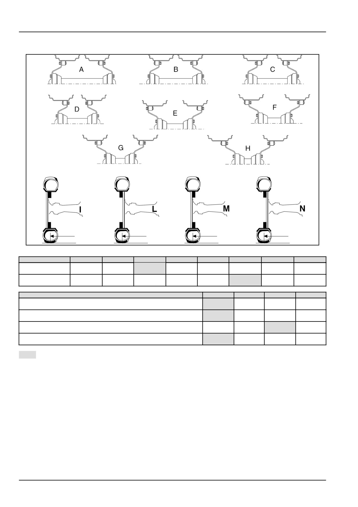
6 - WORKING OPERATIONS
4WD FRONT WHEEL TRACKS
DCSPFNEGB048S3F
2
TIRES
A
B
C
D
E
F
G
H
260/70 R 20
1157 mm
1255 mm
1355 mm
1189 mm
1289 mm
1387 mm
1487 mm
-
280/70 R 20
(45.6 in)
(49.4 in)
(53.3 in)
(46.8 in)
(50.7 in)
(54.6 in)
(58.5 in)
300/70 R20
1157 mm
1255 mm
1355 mm
1189 mm
1289 mm
1387 mm
* 1487 mm
-
320/70 R 20
(45.6 in)
(49.4 in)
(53.3 in)
(46.8 in)
(50.7 in)
(54.6 in)
(58.5 in)
TIRES
I
L
M
N
1225 mm
1319 mm
280/70 R 16
—
—
(48.2 in)
(51.9 in)
1217 mm
1341 mm
280/70 R 16 with rear tires 20 "
—
—
(47.9 in)
(52.8 in)
280/70 R 18
1195 mm
1301 mm
1245 mm
1351 mm
10.5/80 - 18
(47.0 in)
(51.2 in)
(49.0 in)
(53.2 in)
1185 mm
1291 mm
1255 mm
1361 mm
7.50 R 18
(46.7 in)
(50.8 in)
(49.4 in)
(53.6 in)
Rated wheel track setting
(*) Track settings to be made only on the field or on road with the maximum clearance lights extended.
NOTE: Tracks lower then rated setting could require: steering angle reduction, or front axle oscillation angle reduction,
or front fender remotion, if installed.
6-52
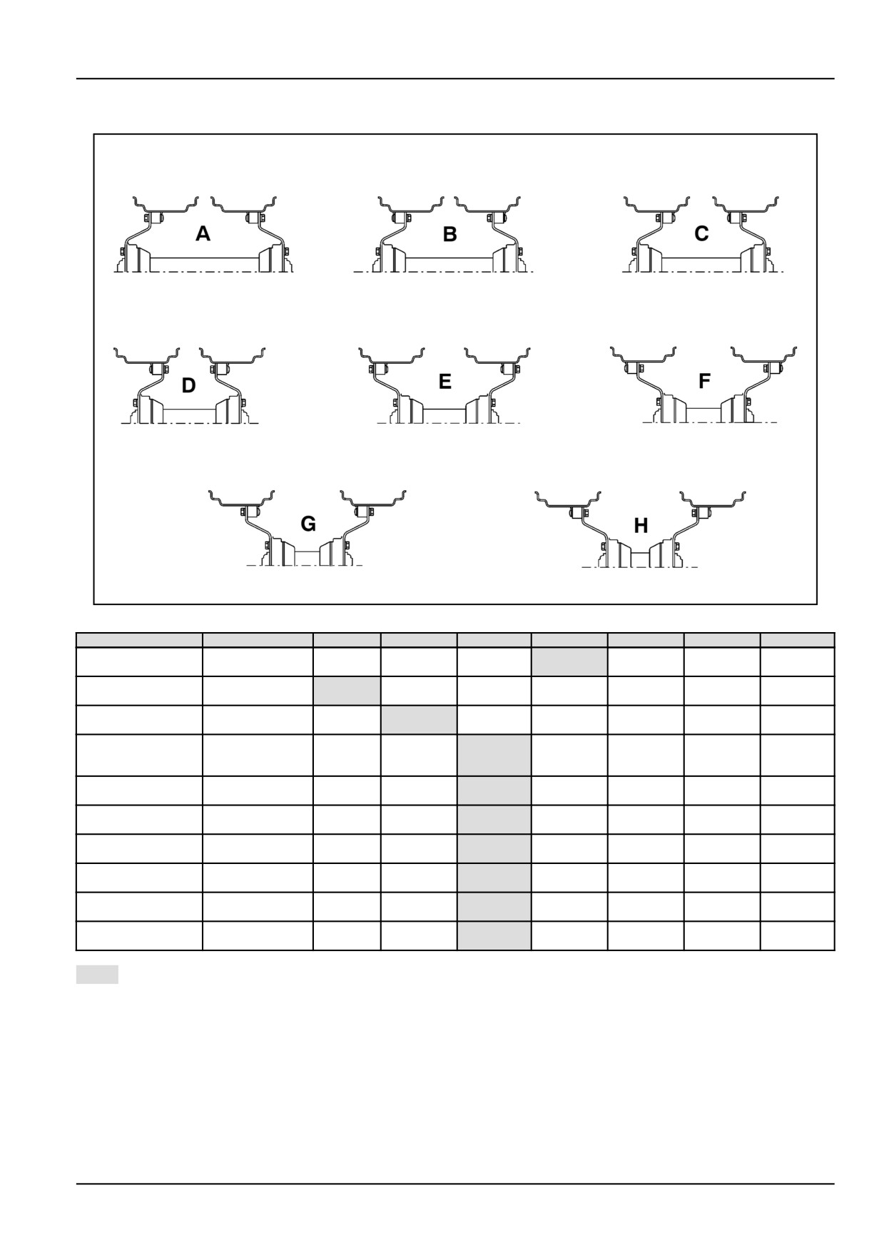
6 - WORKING OPERATIONS
2/4WD REAR WHEEL TRACKS
DCUTDNEGB075S3F
3
TIRES
A
B
C
D
E
F
G
H
1108 mm
1280 mm
1316 mm
1332 mm
1368 mm
380/70 R 20
—
—
—
(43.6 in)
(50.4 in)
(51.8 in)
(52.4 in)
(53.9 in)
1137 mm
1200 mm
1192 mm
1305 mm
1255 mm
* 1368 mm
380/70 R 24
—
—
(44.8 in)
(47.2 in)
(46.9 in)
(51.4 in)
(49.4 in)
(53.9 in)
1142 mm
1255 mm
1137 mm
1250 mm
1310 mm
* 1423 mm
420/70 R 24
—
—
(45.0 in)
(49.4 in)
(44.8 in)
(49.2 in)
(51.6 in)
(56.0 in)
12.4 R 28
1062 mm
1173 mm
1217 mm
1328 mm
* 1462 mm
* 1573 mm
320/85 R 28
—
—
(41.8 in)
(46.2 in)
(47.9 in)
(52.3 in)
(57.6 in)
(61.9 in)
380/70 R 28
13.6 R 28
1096 mm
1207 mm
1183 mm
1294 mm
* 1496 mm
* 1607 mm
—
—
340/85 R 28
(43.1 in)
(47.5 in)
(46.6 in)
(50.9 in)
(58.9 in)
(63.3 in)
1130 mm
1260 mm
1371 mm
* 1419 mm
* 1530 mm
380/70 R 28
—
—
—
(44.5 in)
(49.6 in)
(54.0 in)
(55.9 in)
(60.2 in)
1149 mm
1241 mm
* 1352 mm
* 1438 mm
* 1550 mm
420/70 R 28
—
—
—
(45.2 in)
(48.9 in)
(53.2 in)
(56.6 in)
(61.0 in)
14.9 R 28
1130 mm
1260 mm
* 1372 mm
* 1419 mm
* 1530 mm
—
—
—
380/85 R 28
(44.5 in)
(49.6 in)
(54.0 in)
(55.9 in)
(60.2 in)
1144 mm
1246 mm
* 1358 mm
* 1433 mm
* 1544 mm
420/70 R 30
—
—
—
(45.0 in)
(49.1 in)
(53.5 in)
(56.4 in)
(60.8 in)
1241 mm
1264 mm
* 1296 mm
* 1409 mm
19.5L - 24
—
—
—
—
(48.9 in)
(49.8 in)
(51.0 in)
(55.5 in)
Rated wheel track setting
(*) Track settings to be made only on the field or on road with the maximum clearance lights extended.
NOTE: Tracks lower then rated setting could require: steering angle reduction, or front axle oscillation angle reduction,
or front fender remotion, if installed.
6-53
6 - WORKING OPERATIONS
BALLAST
Ballast
WARNING
Crushing hazard!
Counterweights are very heavy. Always use certified lifting equipment to remove and install the coun-
terweights. Make sure the hardware securing the counterweight(s) to the machine is installed correctly
and the clamp bolts are tightened fully before operating the machine.
Failure to comply could result in death or serious injury.
W0402A
WARNING
Heavy object!
Clear the area around and under the counterweight removal and installation system before installing
or removing counterweights. Keep all unauthorized personnel clear of the area. Make sure all lifting
devices are in good condition and capable of handling the counterweight mass.
Failure to comply could result in death or serious injury.
W0037A
WARNING
Driving hazard!
Be aware that extra weight and bad traction conditions such as mud or ice increase your stopping
distance. Liquid in the tires, weights on the machine or wheels, tanks filled with fertilizer, herbicides,
or insecticides - all these add weight and increase the distance you need to stop.
Failure to comply could result in death or serious injury.
W0338A
If your tractor requires high traction power, the drive wheels may slip due to insufficient grip on the ground, causing
loss of power and speed, increased fuel consumption and premature tyre wear. We therefore advise fitting cast−iron
rings as ballast on the drive wheels, or ballasting wheels with cast iron discs.
When using very long and heavy implements, which could affect the longitudinal stability of the tractor, ballast the
front axle by fitting the appropriate cast−iron counterweights.
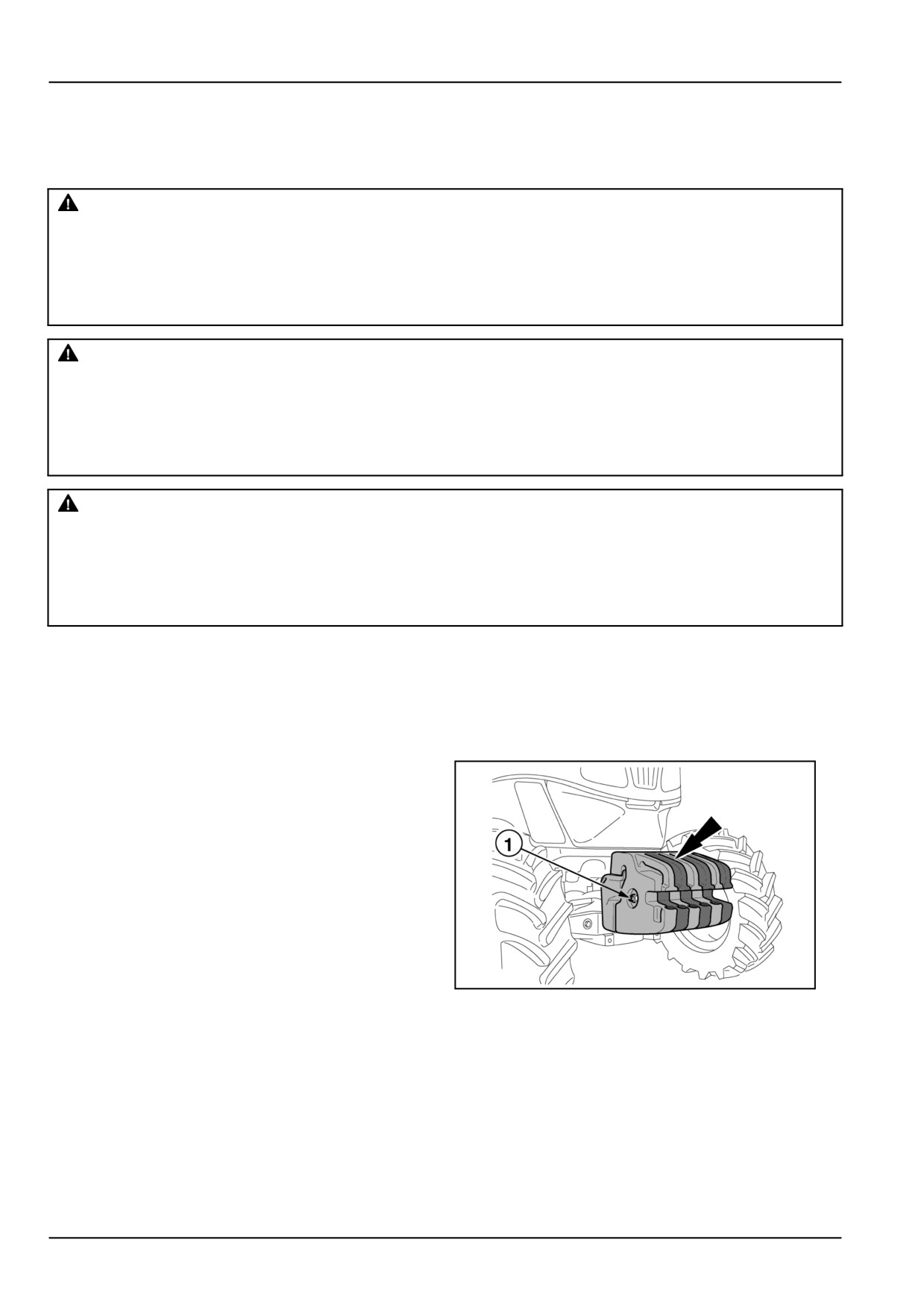
Front axle ballast
•
4 plates each weighing 25 kg (55 lb)
•
6 plates each weighing 25 kg (55 lb).
•
6 plates each weighing 40 kg (88 lb).
To remove the blocks of ballast, unscrew the bolt (1) and
extract the pin.
NOTICE: Do not use the tractor until the plates have been
locked together.
DCSPVEGB008S5F
1
6-54

6 - WORKING OPERATIONS
Rear axle ballasting
4 cast iron rings, of the weight of 50 kg (110.23 lb) each,
for 28” and 30” tyres.
NOTICE: Periodically check the tightness of the front and
rear ballast locking bolts.
DCSPVEGB009S5F
2
6-55
6 - WORKING OPERATIONS
6-56
7 - MAINTENANCE
7 - MAINTENANCE###_7_###
GENERAL INFORMATION
General safety before you service
DANGER
Improper operation or service of this machine can result in an accident.
Do not operate this machine or perform any lubrication, maintenance, or repair on it until you have
read and understood the operation, lubrication, maintenance, and repair information.
Failure to comply will result in death or serious injury.
D0010A
DANGER
Improper operation or service of this machine can result in an accident.
Any unauthorized modifications made to this machine can have serious consequences. Consult an
authorized dealer on changes, additions, or modifications that may be required for this machine. Do
not make any unauthorized modifications.
Failure to comply will result in death or serious injury.
D0030A
WARNING
Avoid injury! Always do the following before lubricating, maintaining, or servicing the machine.
1. Disengage all drives.
2. Engage parking brake.
3. Lower all attachments to the ground, or raise and engage all safety locks.
4. Shut off engine.
5. Remove key from key switch.
6. Switch off battery.
7. Wait for all machine movement to stop.
Failure to comply could result in death or serious injury.
W1023A
WARNING
Maintenance hazard!
Before you start servicing the machine, attach a DO NOT OPERATE warning tag to the machine in a
visible area.
Failure to comply could result in death or serious injury.
W0004A
WARNING
Maintenance hazard!
Always perform all service procedures punctually at the intervals stated in this manual. This ensures
optimum performance levels and maximum safety during machine operation.
Failure to comply could result in death or serious injury.
W0132A
WARNING
Improper operation or service of this machine can result in an accident.
Read and understand the SAFETY INFORMATION Section before you perform any maintenance, ser-
vice, or repairs. Read and understand the specific service procedures for the components you plan
to work with before you start servicing the machine.
Failure to comply could result in death or serious injury.
W0138A
7-1
7 - MAINTENANCE
WARNING
Improper operation or service of this machine can result in an accident.
If you do not understand a maintenance procedure, or doubt your ability to perform a maintenance
procedure correctly, see your authorized dealer.
Failure to comply could result in death or serious injury.
W0157A
WARNING
Personal Protective Equipment (PPE) required.
When assembling, operating, or servicing the machine, wear protective clothing and PPE necessary
for the particular procedure. Some PPE that may be necessary includes protective shoes, eye and/or
face protection, hard hat, heavy gloves, filter mask, and hearing protection.
Failure to comply could result in death or serious injury.
W0353A
WARNING
Moving parts!
Install all covers, panels, and guards after servicing or cleaning the machine. Never operate the ma-
chine with covers, panels, or guards removed.
Failure to comply could result in death or serious injury.
W0135A
WARNING
Avoid injury and/or machine damage!
After installation or service, make sure you remove all tools from the machine.
Failure to comply could result in death or serious injury.
W0902A
7-2
7 - MAINTENANCE
Introduction
This section gives full details of the maintenance procedures required to keep the tractor in conditions of maximum
efficiency. The lubrication and maintenance table provides rapid reference for this purpose.
Maintenance frequency
The service intervals at set times, given in this section, apply when the tractor is used under normal and not harsh
conditions.
These service intervals must be reduced even on a daily basis if necessary when there are adverse conditions (wet-
ness, mud, sand, great dustiness, etc.).
Shortening the interval from one job to the next is particularly recommended for the following parts:
• Cleaning the cab air filters (use in damp or particularly dusty places).
• Radiator cores (use in particularly dusty places).
• Lubricators (use in particularly muddy places).
Environmental Protection
Always bear in mind the rules of environmental protection before servicing this machine and before disposing of
old fluids, lubricants and filters.
• Never pour oil or fluids onto the ground, into the drainage system or into containers that do not have a seal.
• Dispose of all old fluids, lubricants and filters in compliance with the local laws.
• For any further information, please contact your local differentiated waste collection centre or your dealer.
When it is necessary to refill the fuel tank, or top up or change the oil, never forget to place a container under the
component to collect any spillage.
The products mentioned are pollutants and we must therefore prevent them from contaminating the environment in
which we live.
Preventing system contamination
To avoid contamination when changing oil, filters, etc, always clean the area around the fill points, inspection and
drain plugs, dipsticks and filters.
Before connecting external cylinders, make sure that the oil inside is clean, that it has not deteriorated after prolonged
storage and that it is of the type specified. To prevent dirt entering, clean the lubricating nipples before lubrication.
Wipe excess grease from the fitting after greasing.
7-3
7 - MAINTENANCE
Various controls
Check the following components regularly and, if any
Tires
faults are detected, contact your dealer and replace the
damaged parts as necessary:
Always fit and remove tyres in perfectly clean conditions.
Avoid working on the ground.
• Steering linkage ball joints: check that there is no play
Do not use grease when fitting and removing tyres. Use
in the ball joints and that the conical ends are securely
a soap and water solution instead.
in place; also check no grease is escaping from the
When fitting a new or used tyre, inflate it to 3.5 bar
protective hoods to the ball joints, and that the hoods
(50.8 psi) to ensure the correct positioning of the bead.
are in good condition and show no signs of cracks.
Then inflate the tyre to its service pressure.
• Hydrostatic steering cylinder lines: the lines must not
show signs of crimping, cracking or swelling of the ex-
Tyre pressures
ternal sheath; there must be no traces of oil between
the pipe and the connector;
The recommended tyre pressures are given in this man-
ual in specific tables.
• Handbrake lever: check that the ratchet locks securely.
Remember that the values given may differ depending on
the following factors: tyres different from those fitted by
Engine Cooling systems
the manufacturer, tractor ballast type, different conditions
of use, etc.
It is advisable to change the coolant every two years,
The tyre manufacturer should be able to help you decide
even if the total working time of 1200 hours has not been
on the most suitable pressures. Do not forget to check
reached.
the tyre working pressures regularly.
The frequency of such inspection will vary depending on
Radiator
operational and climatic conditions.
If the cooling circuit is to work properly, it is important that
the radiator fins are not clogged.
Clean them regularly, even several times a day if the en-
vironment in which you are working is particularly dusty.
7-4
7 - MAINTENANCE
Body maintenance
Protection against atmospheric agents
Over the years, NEW HOLLAND have introduced a series of measures to protect the tractor from the deterioration
and corrosion which can be caused by various external elements, such as those listed below:
• salinity and atmospheric humidity
• atmospheric pollution (industrial areas);
• abrasive action of solid substances;
• using tractor in the presence of aggressive chemical and/or organic substances;
• physical damage such as dents, abrasions or deep scratches.
The technical response to these problems was:
• highly corrosion−resistant zinc plating;
• paint systems and paints which help the tractor resist corrosion and abrasion;
• application of suitable hardened plastic coatings at points which are particularly vulnerable to corrosion (edges,
projections and sheet−metal welded joints).
Unfortunately, external agents act in various ways according to environmental conditions and tractor use. However,
if the user takes enough care, the tractor can be maintained better and for longer.
The following information is provided to help achieve this aim.
Protection against atmospheric agents
The technical response to these problems was:
• highly corrosion−resistant zinc plating;
• paint systems and paints which help the tractor resist corrosion and abrasion;
• application of suitable hardened plastic coatings at points which are particularly vulnerable to corrosion (edges,
projections and sheet−metal welded joints).
Unfortunately, external agents act in various ways according to environmental conditions and tractor use. However,
if the user takes enough care, the tractor can be maintained better and for longer.
The following information is provided to help achieve this aim.
Bodywork and cab
Where there are abrasions or deep scratches, which expose the underlying metal, they need to be retouched
immediately with genuine products as follows:
• rub down the area thoroughly;
• apply the primer;
• leave to dry and then rub down once more;
• apply the paint;
• lastly, polish.
Maintenance of the paintwork is normally carried out by washing, at intervals that depend on the conditions of use
and the environment.
In areas prone to atmospheric pollution and coastal zones, washing should be carried out more frequently, whereas
if organic or chemical substances are present, wash immediately after the tractor is used. Use a low pressure water
spray, sponge down with a solution of ( 2 - 4 % of shampoo in water), rinsing the sponge frequently. Rinse the tractor
thoroughly and dry, if possible, with a jet of air.
Avoid washing the tractor after it has been standing in the sun and when the engine is still hot in order to protect the
shine on the paint.
7-5
7 - MAINTENANCE
It is good practice to protect the paint by polishing it with specialised products (silicone waxes) from time to time and,
when the paint starts to dull, you can use wax polish which has a slight abrasive action.
Cab maintenance
• Periodically check that no water remains in areas covered with mats or padding.
• Protect the hinges and locks on the doors, roof and opening windows with lubricants and water− repellents.
• Clean the windows with suitable detergents. If necessary, use sulphuric ether.
• Remove the windscreen wiper blade and sprinkle talcum powder on the rubber surfaces.
• Leave the doors partially open.
► WARNING ◄
When washing your tractor, never direct the jet of water horizontally, but only from top to bottom so as not to
reach the following components:
• alternator;
• starter motor;
• air filter;
• connectors and other electrical components;
• especially on models with a roll bar, the ignition key must be inserted in the switch to prevent water getting in.
7-6
7 - MAINTENANCE
Break-in period
During the running-in period (approximately 50 hours of
• front ballast retaining bolts;
work), in addition to carrying out the operations indicated
• front wheel toe-in and steering limiters;
in this section for “Lubrication and Maintenance” after
“every 10 hours of work and “every 50 hours of work”,
• tyre inflation pressures and wear;
we recommend the following:
• oil or fluid leaks;
• Run the engine for a few minutes at low speeds and let
• braking efficiency;
it idle after every cold start.
• steering efficiency;
• Do not let the engine idle for a long time.
•
4WD engagement efficiency;
• Do not use the tractor continually for heavy work.
• differential lock efficiency;
Follow the above recommendations after replacement of
• clutch efficiency;
major parts.
• handbrake efficiency and adjustment;
NOTICE: After the first 50 hours of work, replace:
• PTO efficiency;
• The oil filter cartridge for the transmission and lift
• control valves and lift efficiency;
• On Power Shuttle models, the hydrostatic steering filter
• lights and horn efficiency;
cartridge
• checking the alternator V-belt tension;
• Renewing the fuel filter and bleeding the system
• cleaning the radiator and air−conditioner condenser, if
At the end of the running-in period carry out the following
installed.
checks:
NOTICE: Carry out the operations illustrated in this sec-
• engine sump oil level;
tion at the specified intervals to ensure that your tractor
functions properly.
• transmission oil level;
Remember to make the checks and adjustments (with
•
4WD front axle oil level;
variable frequency depending on environmental and
working conditions) according to the intervals suggested
•
4WD front axle housing oil;
by experience and good sense.
•
4WD front axle final drive oil level
• wheel retaining bolts;
7-7
7 - MAINTENANCE
Fuel supply
WARNING
Fire hazard!
When handling diesel fuel, observe the following precautions:
1. Do not smoke.
2. Never fill the tank when the engine is running.
3. Wipe up spilled fuel immediately.
Failure to comply could result in death or serious injury.
W0099A
Fuel specifications
Refuelling
The quality of fuel used is an important factor for the en-
Before filling the tank, clean the area around the filler cap
gine's subsequent performance and satisfactory service
to prevent foreign bodies getting inside and contaminating
life. Fuels must be clean, well- refined, and non- corro-
the fuel. Remove the cap and place in a clean area during
sive to fuel system parts. Be sure to use fuel of a known
refuelling. After refuelling replace the cap and tighten it
quality from a reputable supplier.
fully.
Fuel tank capacity:
Storing fuel
Normal tank: 77 l (20 US gal)
Take all necessary precautions to ensure that stored fuel
Reduced tank: 67 l (18 US gal)
is not contaminated by dirt, water or any other substance.
NOTE: If the fuel tank cap should be lost or damaged,
• Store fuel in black iron tanks, not galvanized tanks, as
the zinc coating will react with the fuel and form com-
replace it with an original spare part.
pounds that will contaminate the injection pump and in-
jectors.
Diesel
• Shelter the storage drums from direct sunlight and tilt
NOTICE: The Diesel fuel approved for your tractor's en-
them slightly so that sediment inside can be removed
gine must comply with the EN590 standard (or the equiv-
through the outlet pipe.
alent).
• To facilitate moisture and sediment removal, provide a
Be aware that use of diesel not complying with the above
drain plug at the lowest point at the end opposite the
mentioned Specification Standard could lead to severe
outlet pipe.
damage to the engine and to the fuel system. In addition,
• If fuel is not filtered from the storage tank, put a funnel
bear in mind that use of fuels that are not approved can
with a fine mesh screen in the fuel tank filler neck when
invalidate the terms of Warranty.
refueling.
• Organize fuel supplies so that summer fuel is not kept
for too long and then used in winter.
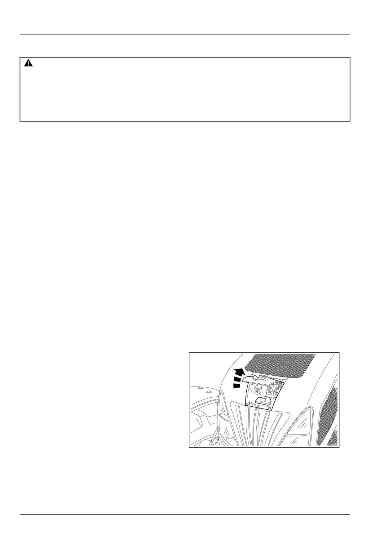
Fuel tank flap
A flap provides quick access for filling the fuel tank, with-
out it being necessary to lift the bonnet.
MOIL13TR00717AA
1
7-8
7 - MAINTENANCE
General specification - Biodiesel Fuels
Fatty Acid Methyl Ester Biodiesel (Biodiesel Fuel) con-
With Biodiesel Fuels, it may be necessary to change the
sists of a family of fuels derived from vegetable oils
engine oil, engine oil filter and fuel filter elements more
treated with methyl esters.
frequently than with Diesel Fuels. Biodiesel Fuel can re-
move rust and particles from the inside of on-site fuel
NOTICE: Biodiesel Fuel blends are approved for your en-
storage tanks that would normally adhere to the sides
gine only if they comply with EN14214 Specification Stan-
of the tank. Like particle deposits that commonly occur
dards or ASTM D6751.
with Diesel Fuel, these particles can become trapped by
the machine fuel filters, causing blockage and shortening
NOTICE: It is imperative that you check which blend is ap-
filter life. In cold weather, this is more likely to happen.
proved for your engine with your NEW HOLLAND dealer.
Consult your NEW HOLLAND dealer for information on
Be aware that the use of Biodiesel Fuel that does not
cold weather operation and proper maintenance intervals
comply with the Standards mentioned above could lead
when using any Biodiesel Fuel blend.
to severe damage to the engine and fuel system of your
machine. The use of fuels that are not approved may void
When handling Biodiesel Fuel, care must be taken not to
NEW HOLLAND Warranty coverage.
allow water into the fuel supply. Biodiesel Fuel will actu-
ally attract moisture from the atmosphere.
Biodiesel Fuel Usage Conditions
Fuel tanks must be kept as full as possible to limit the
NOTICE: The Biodiesel Fuel must meet the fuel Specifi-
amount of air and water vapors in them. It may be nec-
cation mentioned above.
essary to drain the fuel filter water tap more frequently.
Biodiesel Fuel must be purchased from a trusted sup-
Potential oxidation and stability could be a problem with
plier that understands the product and maintains good
the fuel stored in the machine.
fuel quality. Biodiesel Fuel must be pre-blended by the
NOTICE: Machines must not be stored for more than
supplier. Mixing Biodiesel Fuels on-site can result incor-
three months with Biodiesel Fuel blends in the fuel sys-
rect mixture that can lead to problems with both engine
tem.
and fuel system.
If long storage periods are necessary, the engine must
Engine performance is affected by the use of Biodiesel
run on Diesel Fuel for 20 hours to flush the Biodiesel Fuel
Fuel. There may be up to 12 % reduction in power or
out of the engine fuel system prior to storage.
torque depending on the blend used.
NOTICE: Biodiesel Fuel must not be stored in on-site stor-
NOTICE: DO NOT modify the engine and/or injection
age tanks for more than three months.
pump settings to recover the reduced performance.
Any spillage of Biodiesel Fuel must be cleaned up imme-
The reduced power must be accepted if using any
diately before it can cause damage to the environment
Biodiesel Fuel blend.
and the paint finish of the machine.
Some modification may be required to allow your engine
Before using Biodiesel Fuel blends you should consult
to run Biodiesel Fuel. Consult you dealer for complete
with your dealer to receive full information about the ap-
information on these modifications.
proved blend for your machine and any detailed condi-
tions of its usage.
Biodiesel Fuel has a higher cloud point than Diesel Fuel.
NOTICE: Be aware that not fulfilling the requirements
NOTICE: The use of high Biodiesel Fuel blends are not
and conditions of Biodiesel Fuel usage will void your ma-
recommended in cold weather conditions.
chine’s NEW HOLLAND Warranty coverage.
7-9