New Holland Tractor T4.75F, T4.85F, T4.95F, T4.105F. OPERATOR’S MANUAL (2013) - page 2
3 - CONTROLS/INSTRUMENTS
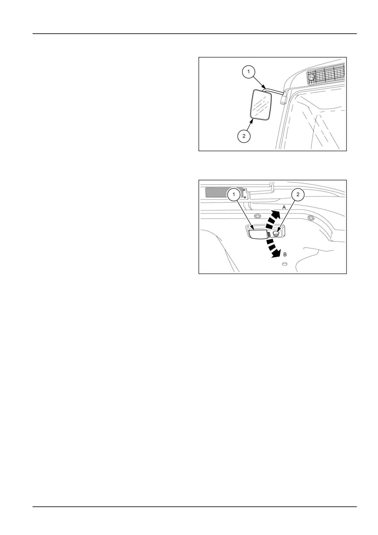
Rear view mirror external
The mirror can be adjusted in two ways, as described
below:
• turn the support bracket (1) on its axis to adjust the an-
gle of the mirror;
• turn the mirror (2) into the position that provides the best
rear view.
MOIL13TR00494AA
7
Interior cab light
The ceiling lights unit comprises a courtesy light (1) and a
reading light (2), both are powered with the key on.
The internal lights are controlled by a three-position
switch:
• A = courtesy light (1) on
• central position = lights OFF
• B = courtesy light (1) off and reading light (2) on.
MOIL13TR00496AA
8
3-3
3 - CONTROLS/INSTRUMENTS
Heating system
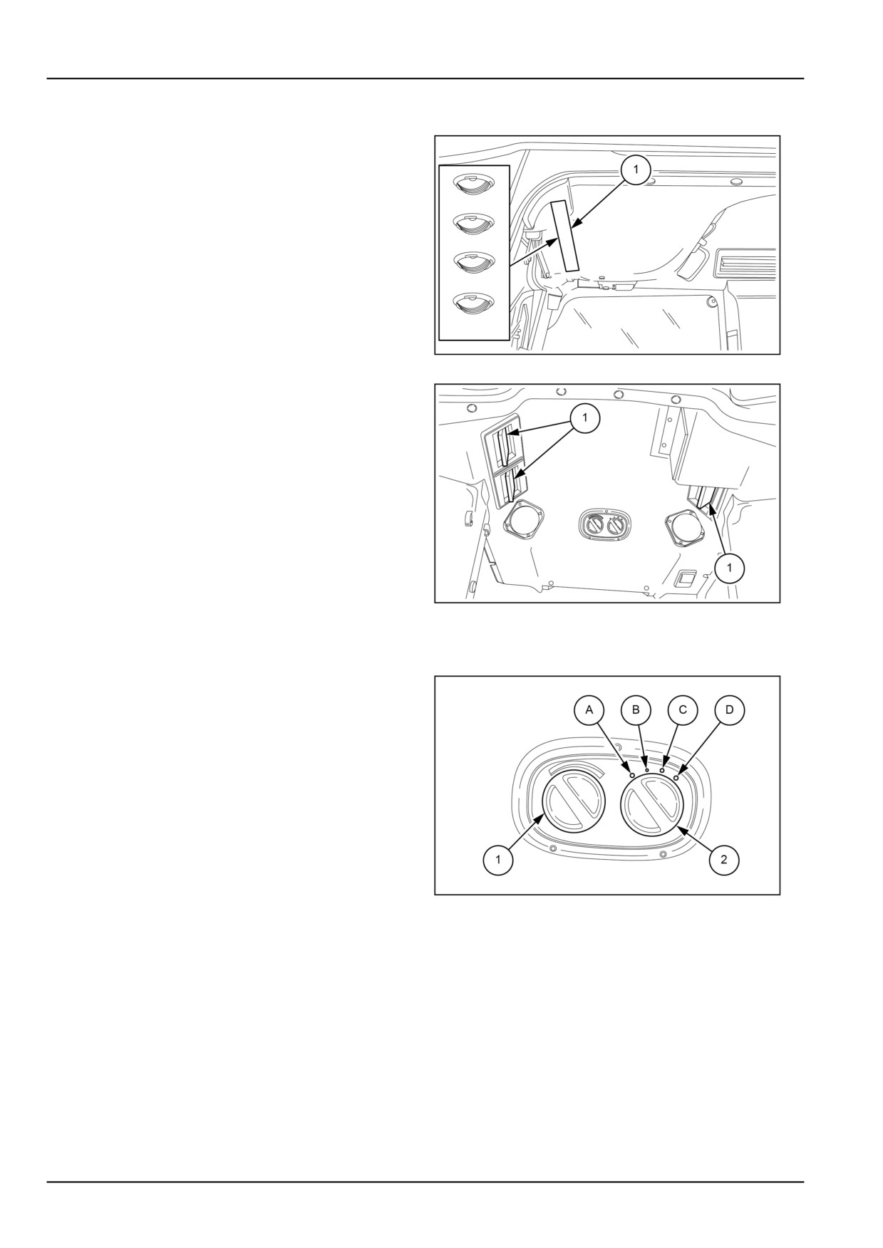
Adjustable vents
On the roof inside the cab there are four adjustable vents
(1). The vents can be adjusted independently to direct hot
or cold air on the windscreen and side windows inside the
cab. To open, press on one side and turn the vent to direct
the air flow where required.
MOIL13TR00497AA
1
Air re-circulation vents
Air may be selected from inside or outside the cab by
adjusting the side recirculation vents (1) which can be
placed in two positions:
• Vents closed: air is drawn from outside the cab through
the lateral filters. Fresh air drawn into the cab from
outside is always filtered.
• Vents open: the greater part of the air is drawn from
inside the air through the vents.
NOTE: With the fan in operation and doors, windows, and
recirculation vents closed, the pressure inside the cab is
MOIL13TR00498AA
2
greater than the external pressure. Consequently, air can
only enter the cab through the lateral filters, after suitable
filtering.
Ventilation and heating
By turning the temperature adjustment knob (1) counter
clock-wise (fully to the left), the circulation of hot air in the
cab is interrupted; by turning the knob clockwise (fully to
the right), maximum cab air temperature is selected. With
the electric fan (2) is possible change the quantity of air
leaving by the adjustable vents.
The electric fan switch is powered up when the starter key
is ON position.
A Electric fan OFF.
B Low speed.
C Medium speed.
MOIL13TR00499AA
3
D High speed.
3-4
3 - CONTROLS/INSTRUMENTS
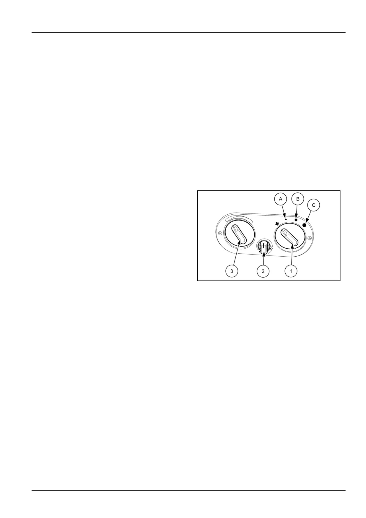
Heating, ventilation or air-conditioning control
The air-conditioning system can supply either cool or
from entering the cab; it is also advised to close the re-cir-
warm dehumidified air.
culation vents.
To use the system, proceed as follows.
If only the dehumidification function on the air conditioning
NOTICE: When the engine is not running, the air condi-
system is required, without lowering the air temperature,
tioner will not work because the compressor is driven by
turn the knob (3) clockwise until the desired temperature
the engine.
is obtained.
Starting
To restore the temperature in the cab after a prolonged
halt in the sun, start the tractor, switch on the air condi-
With the engine running and the electric fan ON, turn the
tioning and after about a minute open the rear fanlight or
knob (2) clockwise to start the air conditioner.
the roof to let the hot air escape.
NOTE: Always switch the electric fan on before the air
conditioning. The air conditioning cannot work when the
Stopping
electric fan is off.
Before stopping the engine, always turn the electric fan
After running for a few minutes, the inspection glass on
knob (1) and the air-conditioner knob (2) anticlockwise
the top of the dehydrating filter should be clear and not
into the OFF position.
contain any bubbles.
If this does not occur, switch off the air-conditioning and
seek specialist help at your dealer.
Adjustment
For a correctly air conditioned cab, open the re-circulation
vents when the air conditioning is running, and keep the
doors, roof and rear window closed. To lower the tem-
perature in the cab and, at the same time, reduce the air
humidity, turn the knob (3) counter-clockwise until the de-
sired temperature is obtained.
NOTICE: Before starting the engine, check that the air
conditioning is OFF.
MOIL13TR00469AA
1
NOTE: When working in very dusty environments, the
cab pressure may have to be increased to prevent dust
3-5
3 - CONTROLS/INSTRUMENTS
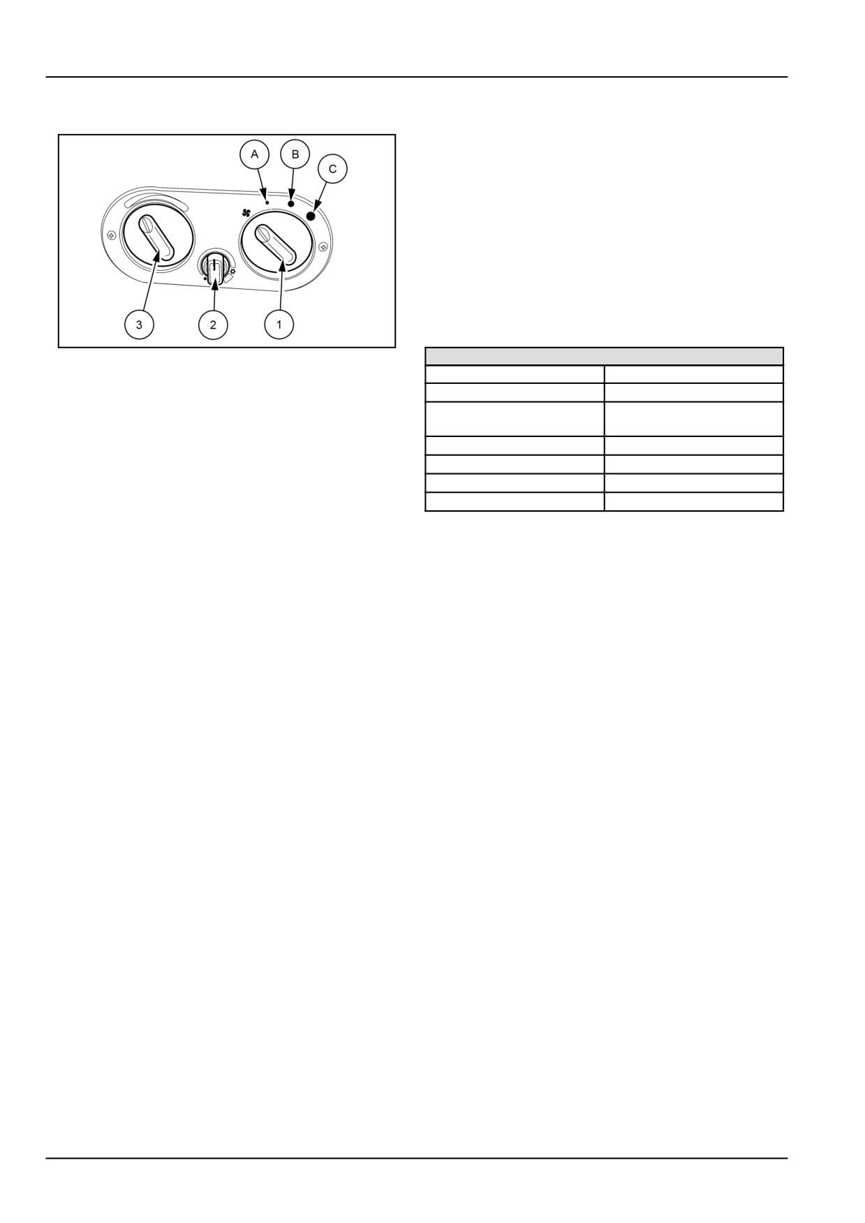
Cab air conditioning controls
Annual maintenance
At the start of the season, have the specialist personnel
from the NEW HOLLAND service network carry out the
following operations:
• Check the oil level in the compressor
• Check system pressure and, if necessary, fill the sys-
tem with HFC R134A
• Drain the air conditioning system and replace the
de-
hydration filter, only if strictly necessary.
• Fill the system with HFC R134A
• Check operation of system.
MOIL13TR00469AA
2
SPECIFICATIONS
Coolant
HFC R134A
3-speed electric fan control knob (1)
Quantity
1.2 kg (2.6 lb)
Compressor
SANDEN SD - 5H11
-
The fan operates with the ignition key in the starting po-
6332
sition.
Number of cylinders
5
A Low speed.
Capacity
155 cm³ (9.5 in³)
B Medium speed.
Oil type
SANDEN SP20
C High speed.
Quantity of oil
180 g (6.3 oz)
Air conditioning and temperature control
knob (2)
The system operates with the ignition key switched on.
With the electric fan knob (1) in positions A - B or C, turn
the knob (2) clockwise and pass the first click to turn on
the air-conditioner. To lower the temperature of the air
coming into the cab, turn the knob (2) clockwise.
Heater control knob (3)
Turn knob (3) fully clockwise (to the right) for maximum
heat. To shut off the water supply to the heater and switch
off the heater, turn the knob (3) fully counter-clockwise.
Periodical inspections
At least once every three months:
• Remove any foreign matter from the condenser and
evaporator fins.
• Check the tension of the compressor belt.
• Check the condition of the tubing, connections and
mounting brackets.
• Check that the fixing screws and nuts, pulleys and com-
pressor are correctly tightened.
3-6
3 - CONTROLS/INSTRUMENTS
Cab air filter
DANGER
Chemical hazard!
The cab air filters are designed to remove dust from the air, but will not keep out chemical vapor.
Extended periods of exposure to pesticides could cause death or personal injury. Follow the chemical
manufacturer's directions for protection from dangerous chemicals.
Failure to comply will result in death or serious injury.
D0060A
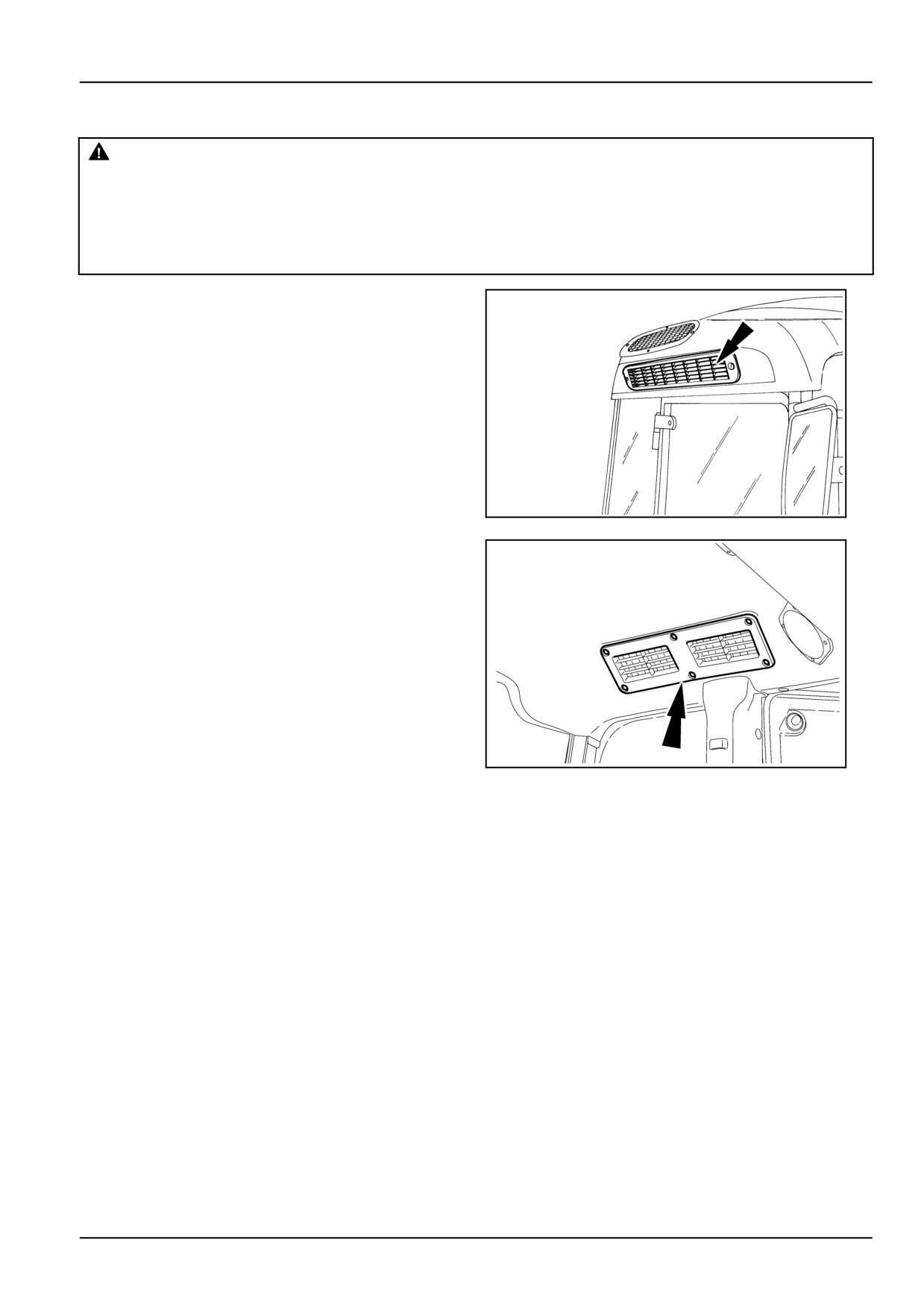
The cab ventilation system has four filters, two pollen fil-
ters for fresh air drawn into the cab from outside fig.
1,
and two for recirculated air fig. 2.
NOTICE: The cab air filters are designed to remove dust
from the air, but they are not effective against chemical
vapours. Follow the chemical manufacturer's directions
regarding the precautions to take.
NOTICE: Remember that the cab air filters do not gener-
ally protect against pesticides. Protection against these
products can only be obtained by taking the specific pre-
cautions required for each individual product. These pre-
cautions must be taken for all types of filter, in strict ac-
cordance with the instructions for use and maintenance.
DCSPVNEGB080S3A
1
DCSPVNEGB081S3A
2
3-7
3 - CONTROLS/INSTRUMENTS
Active-Carbon Air Filter
DANGER
Chemical hazard!
When replacing the filter, pay attention to the sticker on the filter. For correct operation, the specified
anti-pollen or active carbon filter must be used and cannot be interchanged.
Failure to comply will result in death or serious injury.
D0007A
NOTICE: the active carbon air filters do not guarantee full
when working in very dusty areas; they could get clogged
protection against all pesticides. As a result, using them
very quickly and become ineffective.
does not relieve you from having to comply with the safety
rules recommended for using each single product.
When replacing the active carbon filters at the end of the
job, return them to the original packaging, making sure
Even though it is possible to pressurize the inside of the
they are carefully sealed.
cab to restrict entry of chemical vapours, you must any-
how always follow the safety procedures set down by the
The filters must never be cleaned. Their durability is
chemicals manufacturer and use appropriate Personal
stated on the label applied by the manufacturer. They
Protective Equipment (PPE).
must in any case be replaced every 200 h or 2 years.
The use of active carbon filters ensures a comfortable and
Old filters must be disposed of in compliance with the laws
clean work environment and provides suitable protection
in force.
against dust. However, do not use active carbon air filters
3-8
3 - CONTROLS/INSTRUMENTS
OPERATOR'S SEAT
Operator seat
DANGER
Loss of control hazard!
DO NOT make seat or steering adjustments while the machine is in motion. Ensure all adjustments
are locked prior to use. Check the tightness of the securing screws and that the adjustment controls
are working properly. Fitting and/or repairing the seat should only be performed by skilled personnel.
Failure to comply will result in death or serious injury.
D0008A
Before operating the tractor, it is important to adjust the seat to the most comfortable position. See the following text
and illustrations for details.
Mechanical seat
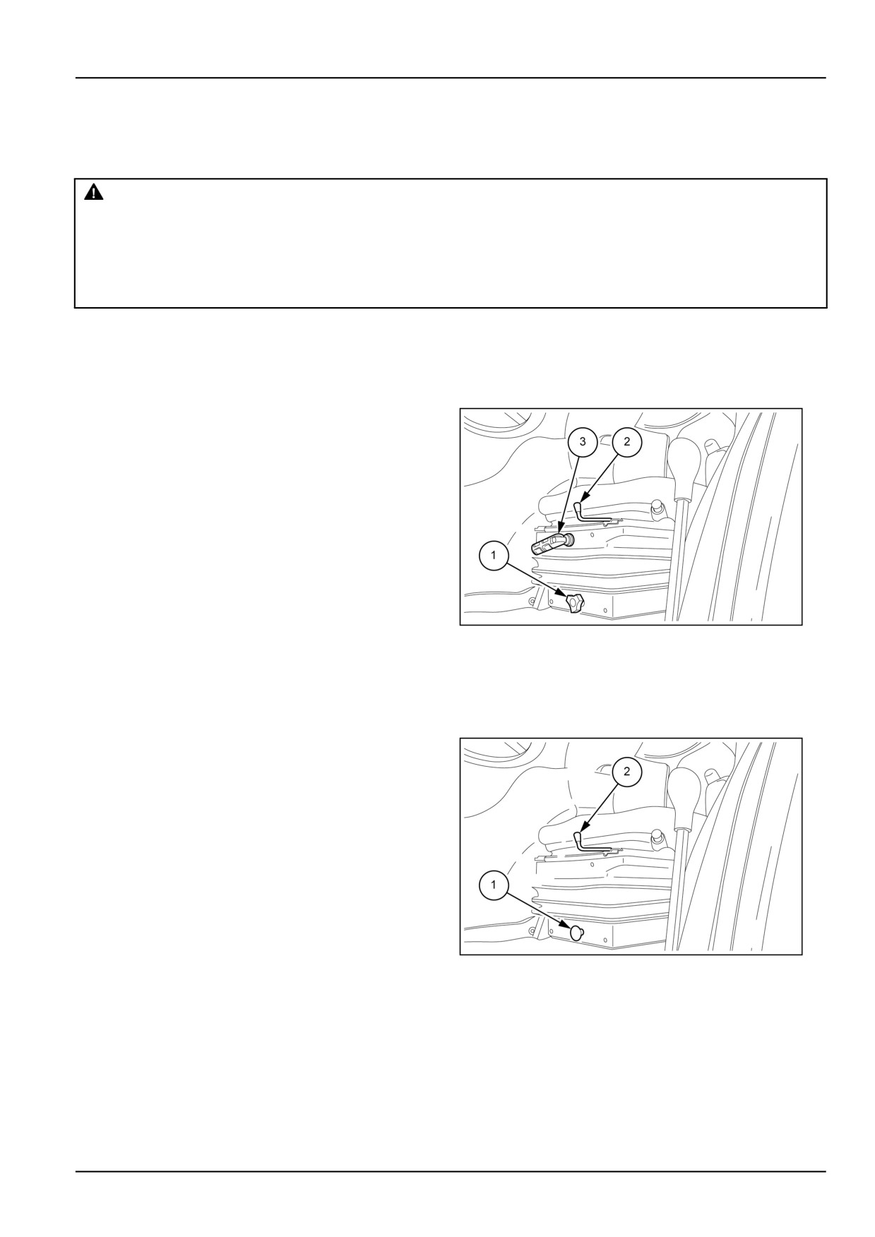
The driver’s seat has adjusters for its suspension, height
and distance from the controls. You can therefore select
the most suitable position for driving.
Adjustment of distance from controls
From the driver's seat, pull the lever (1) sideways and
move the seat forwards or backwards. After moving the
seat, release the lever, ensuring that the seat is locked in
the chosen position.
Adjusting the seat suspension
Seat suspension can be adjusted by means of a han-
dle (2). Turn the handle until your approximate weight is
shown on the scale in the window (3) (where applicable).
MOIL13TR00479AA
1
Seat height adjustment
Turn the knob (4) to one of the three marked positions.
Air suspension seat (on request)
Adjusting the seat suspension
Adjustments to the air suspension are made by operating
the air compressor control button (1). To set the suspen-
sion and ride height, fully lower the seat. Pull the control
button (1), until all the air has been discharged. Turn the
ignition switch “ON” (first click). Sitting in the seat, push-in
and hold the control (1), the air compressor will start to
pressurise the suspension. Let go of the control when
the seat has reached the desired height. To make further
height adjustments, operate the air compressor control,
as required, to raise or lower the seat.
Adjustment of distance from controls
From the driver's seat, pull the lever (2) sideways and
MOIL13TR00481AA
2
move the seat forwards or backwards. After moving the
seat, release the lever, ensuring that the seat is locked in
the chosen position.
3-9
3 - CONTROLS/INSTRUMENTS
Safety belts
WARNING
Equipment failure could cause accident or injury!
Always fasten seat belt securely before operating the machine. Inspect seat belt parts for wear and/or
damage. To ensure operator safety, replace any and all damaged parts of the seat belt prior to oper-
ation.
Failure to comply could result in death or serious injury.
W0046A
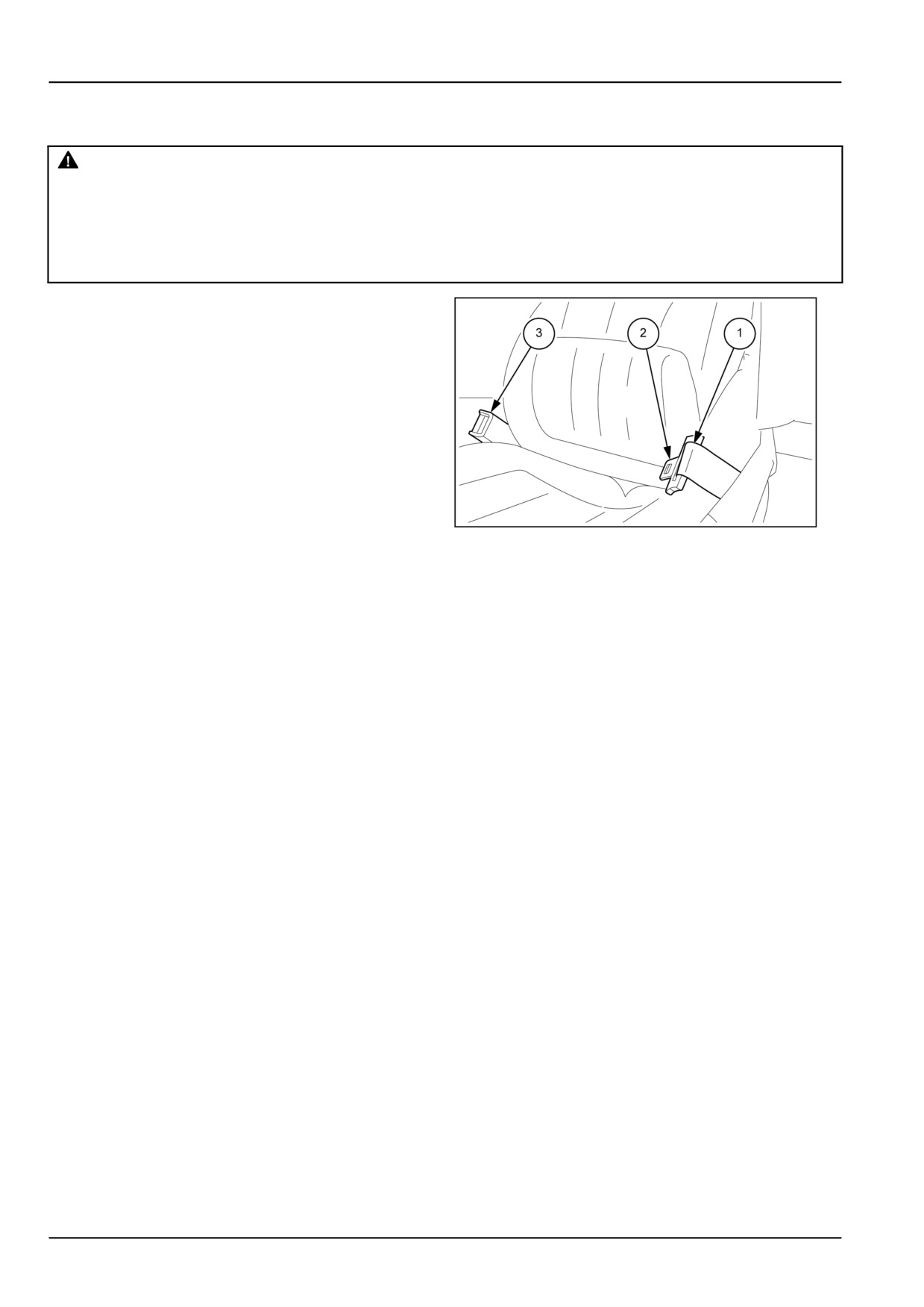
To fasten the safety belt (1), insert the tongue (2) into the
slot in the buckle (3).
MOIL13TR00480AA
3
3-10
3 - CONTROLS/INSTRUMENTS
FORWARD CONTROLS
Analogue dashboard
MOIL13TR00381FA
1
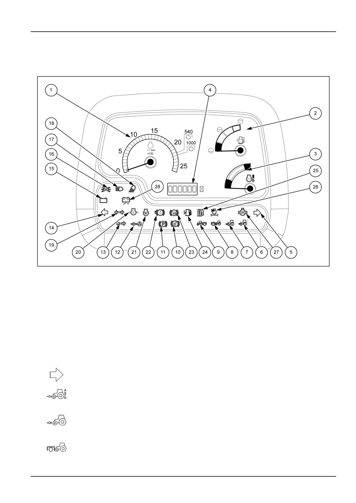
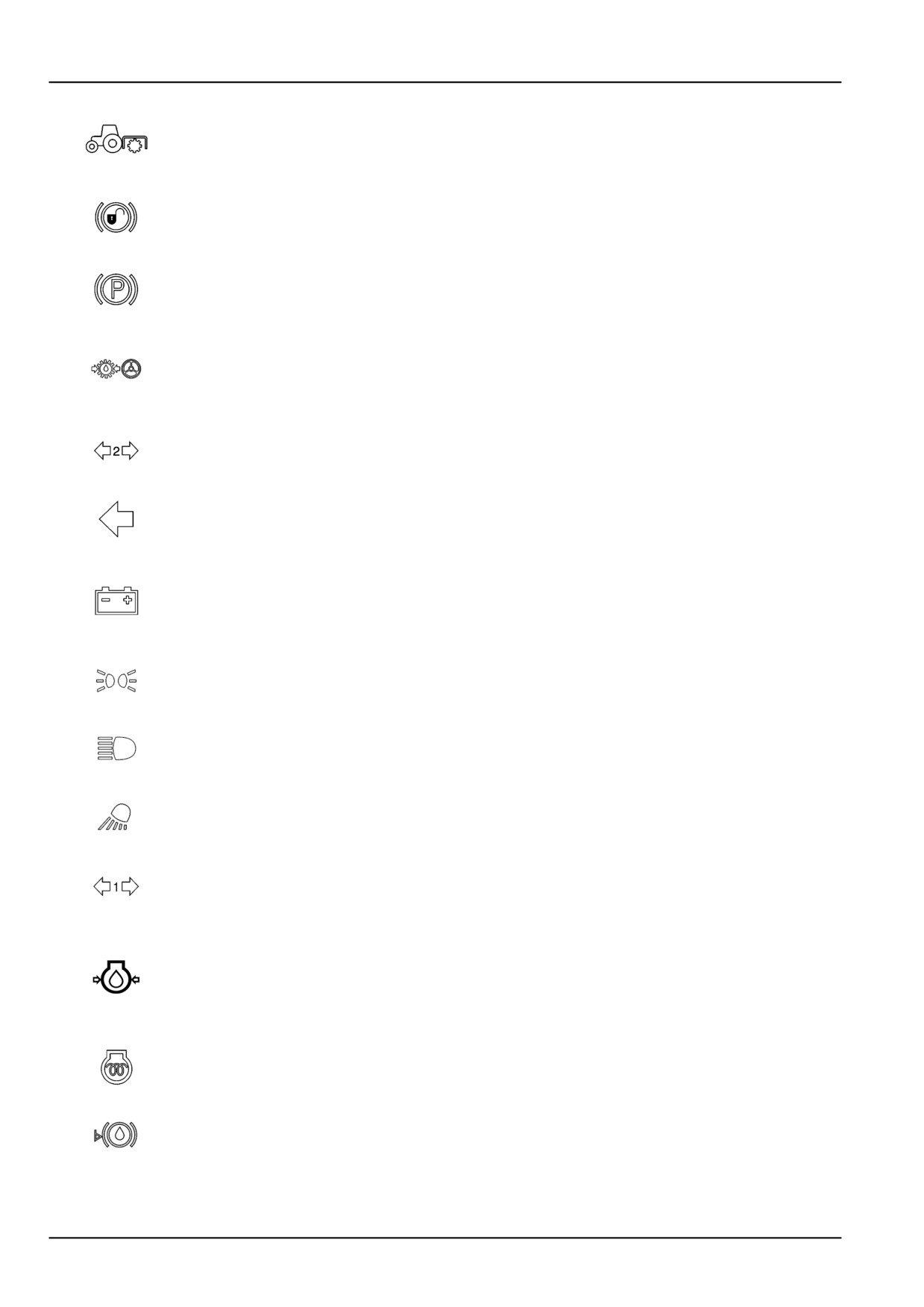
The indicator lights on the control panel inform you of the operational condition of the machine. Some of these indicate
faults arising during operation. An indicator light coming on may be followed by a continuous or intermittent buzzer.
Depending on the severity of the trouble, the alarm will sound.
1
Tachometer
2
Fuel gauge
3
Engine coolant temperature gauge
4
Hours worked counter
Right direction indicator (green)
5
Flashes at the same time as the right−hand turn lamps.
Automatic four−wheel drive (green)
6
Lights up when permanent four−wheel drive is selected by means of the relevant push button.
Four−wheel drive (green)
7
Lights up when front−wheel drive is engaged automatically.
Front power take−off (amber)
8
Lights up when the power take−off is engaged (if fitted).
3-11
3 - CONTROLS/INSTRUMENTS
Rear power take−off (amber)
9
Lights up when the power take−off is engaged.
Brake pedals not latched (red)
10
The indicator lights up to signal when brake pedal latching is not blocked. This warning light is only
active for markets that require signaling failed brake pedal latching.
Handbrake (red)
11
Indicates that the handbrake is on (with starter key inserted).
Power steering oil pressure (red)
The light should go out a few seconds after the engine is started. If the light remains on, particularly
12
when the tractor is moving, contact your dealer. With the engine running at minimum revs and the
tractor stationary, the light may come on without indicating a problem.
Second trailer direction indicator (green)
13
Flashes at the same time as the tractor turn indicators, if connected.
Left direction indicator (green)
14
Flashes at the same time as the left−hand turn indicators.
Abnormal battery charging system operation (red)
It should go out once the engine starts. If the light stays on when the engine is running, stop and
15
find the cause of the problem. May light up when the engine is idling, but does not necessarily
indicate a fault.
Side lights (green)
16
Lights up when the sidelights are switched on.
Full−beam headlights (blue)
17
The light illuminates when the headlights are on main beam.
Work lights (amber)
18
Lights up when the working lights are switched on (cab models only).
First trailer direction indicator (green)
19
Flashes at the same time as the tractor turn indicators, if connected.
Engine oil pressure (red)
The light should go out a few seconds after the engine is started. If the light stays on when the
20
engine is running, stop and find the cause of the problem. If the light remains on, particularly when
the tractor is moving, contact your dealer. When the engine is warmed up and running at minimum
speeds, with the tractor stationary, the light may illuminate, even if no faults are present.
Grid Heater (amber)
21
The indicator lights up when the grid thermostarter is turned on by the ignition key.
Brake fluid level (amber)
22
The light comes on when the brake fluid pressure is low.
3-12
3 - CONTROLS/INSTRUMENTS
Trailer brake (red)
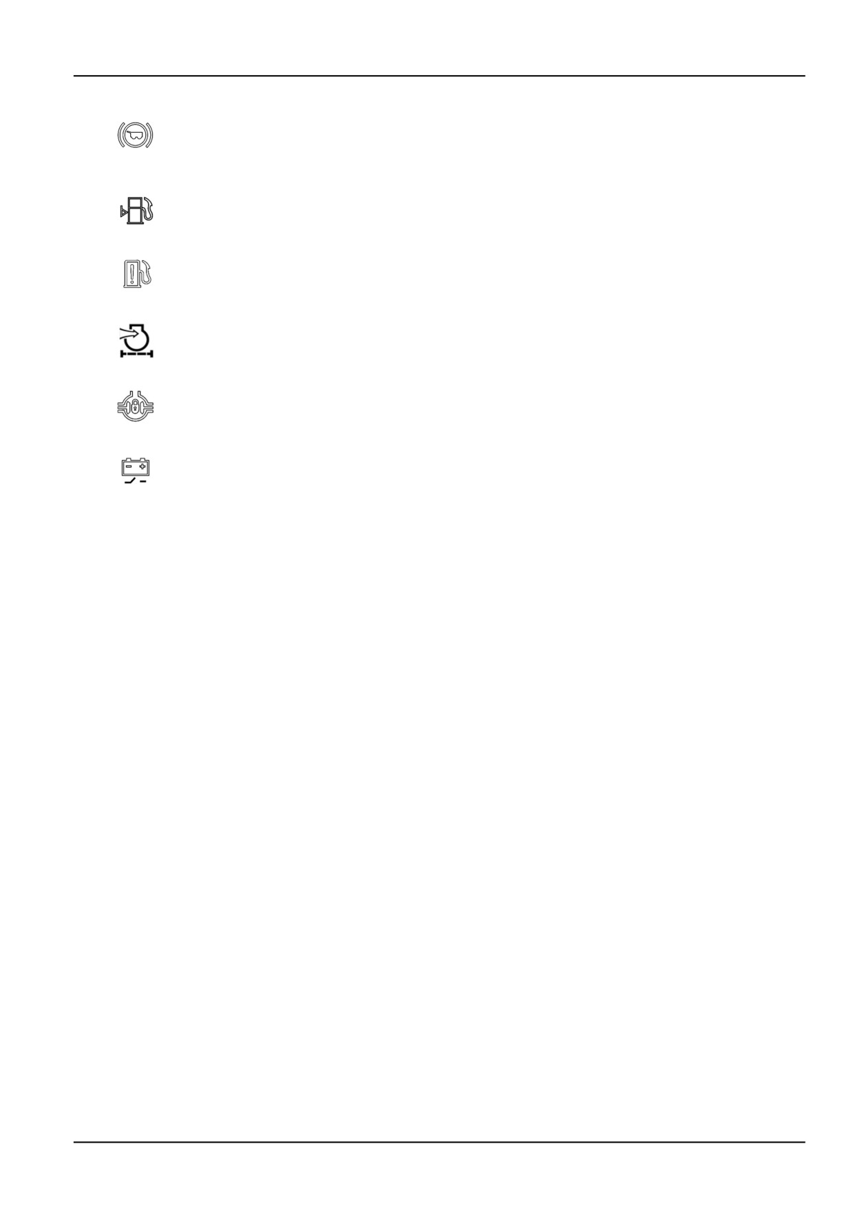
Comes on, with the engine running, when the brakes are applied with the tractor brakes coupled
23
together for road driving. The light comes on whenever the handbrake is on or when the brake
fluid pressure is low.
Fuel level low (amber)
24
The light comes on when the tractor needs refuelling.
25
Water in fuel (amber)
Engine inlake air filter blocked (amber)
26
The light comes on when the engine air filter cartridge is totally or partially clogged and needs
servicing. Stop the tractor and service it as described in maintenance section.
Differential lock (amber)
27
Lights up when the differential lock is ON.
Battery cut-out (amber)
28
It lights up whenever the battery is disconnected from the electric system with the specific control.
3-13
3 - CONTROLS/INSTRUMENTS
Speedometer/tachometer
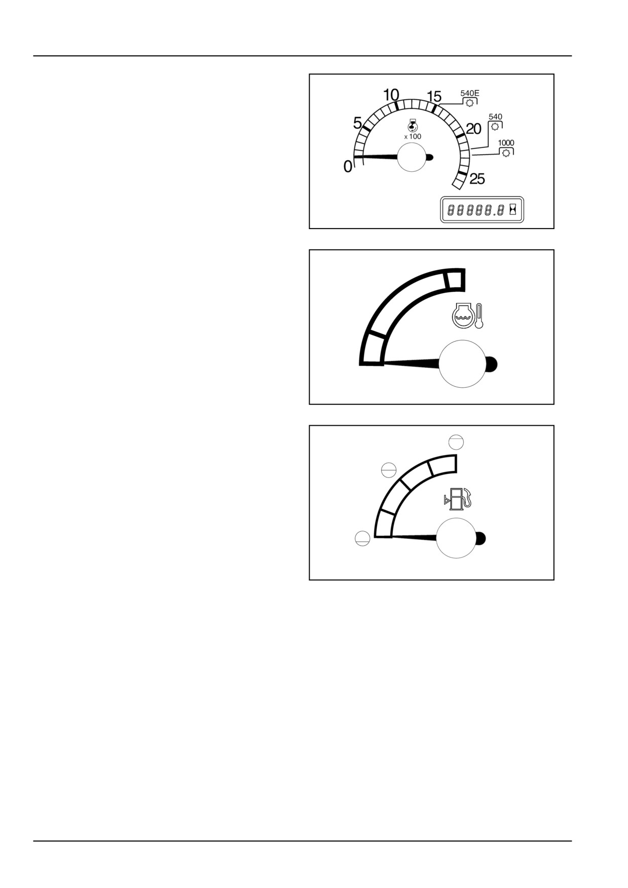
Engine rev counter and six−figure hour meter: the figures
on the black background count the hours of work and that
on the red background (last figure on the right) show the
tenths of an hour. The green and blue sectors show the
number of engine rpm required to reach standard power
take−off speed.
• Green mark = PTO at 540 RPM
• Blue mark = PTO at 1000 RPM
DCSPVNEGB008S3A
2
Engine coolant temperature gauge
• Green area = normal temperature
• White area = temperature too low.
• Red area = engine overheating.
In this case, slow the engine to idling speed (without stop-
ping the engine) and, if the light stays on, have the cooling
system checked.
DCSPVNEGB009S3A
3
Fuel gauge
Shows fuel level in the tank. When the tank is full, the
pointer moves completely to the right. When the fuel level
falls below 1/4, the needle moves into the red area.
DCSPVNEGB010S3A
4
3-14
3 - CONTROLS/INSTRUMENTS
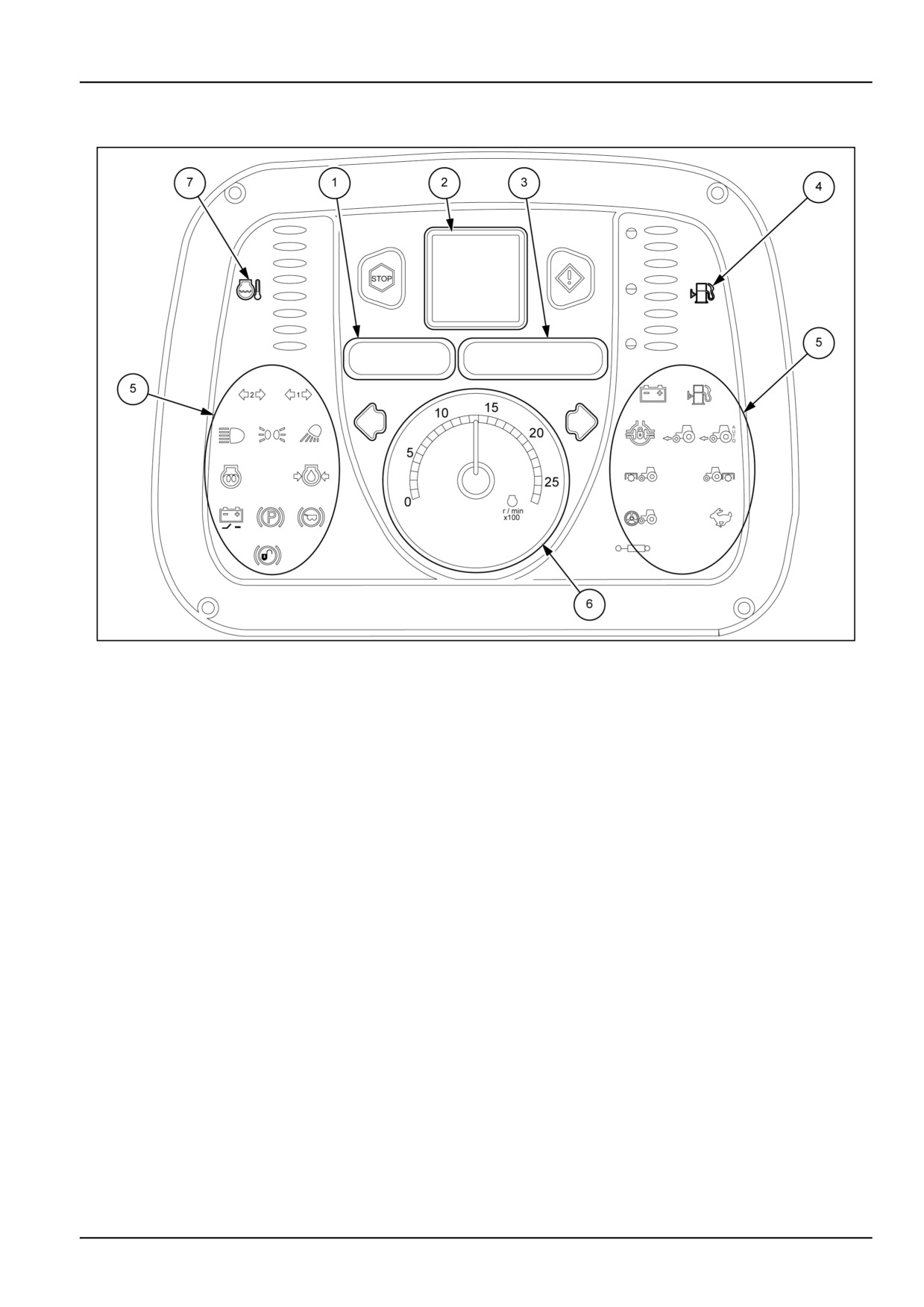
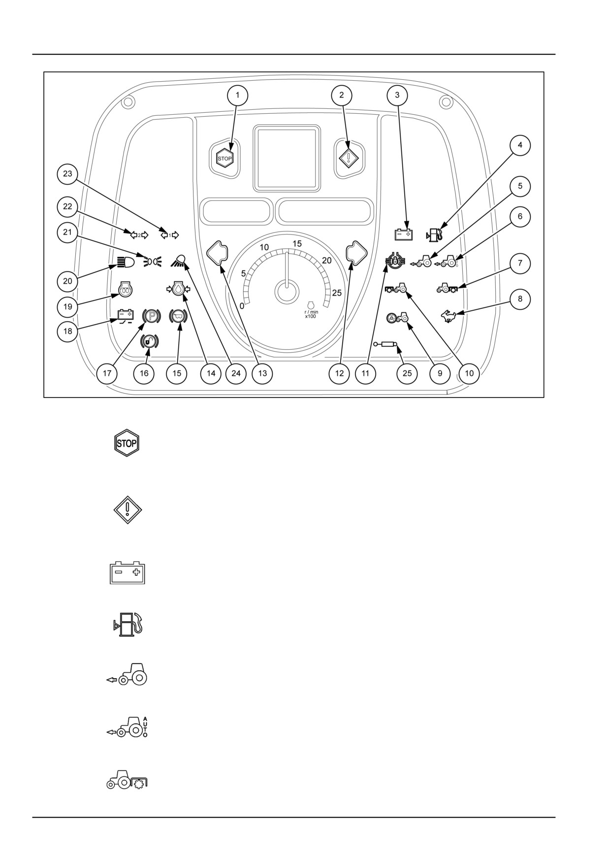
Digital dashboard
MOIL13TR00299FA
1
1. Left-hand digital display − This display shows the trac-
4. Fuel level histogram
tor ground speed in - km/h (- mph)
5. Warning lights
2. Information display - The display shows information on
6. Tachometer/rev-counter
the operational condition of the machine in the form of
symbols or code numbers.
7. Engine coolant temperature indicator histogram
3. Right-hand digital display - This display provides the
following information:
• Rear PTO speed or, where applicable, the front one.
• Clock.
• Position of the rear lift or, where applicable, of the
front one.
3-15
3 - CONTROLS/INSTRUMENTS
MOIL13TR00298FA
2
Stop warning light (red)
If the red “Stop” warning light comes on, switch off the tractor immediately and look
1
for the cause. A warning symbol will appear on the display confirming the location of
the fault.
Indicator lamp (amber)
This indicator light comes on and the display shows a warning symbol . The light blinks
2
for 4 seconds, after which the symbol on the display disappears and the indicator light
stays on steady. To display the fault, you need to go to the menu. Stop the tractor
and investigate the cause of the trouble.
Battery charging system failure (red)
3
This warning light should switch off as soon as the engine starts. If the light stays on
when the engine is running, switch off the engine and find the cause of the problem.
Fuel gauge (amber)
4
The light comes on when the tractor needs refuelling.
Four−wheel drive (green)
5
This warning light comes on when the four−wheel drive is automatically engaged.
Four−wheel drive automatic control (green)
6
This warning light comes on when with the respective button you select the automatic
four−wheel drive engagement mode.
Power take−off (amber)
7
This warning light comes on when the engine is running and the power take-off is
engaged.
3-16
3 - CONTROLS/INSTRUMENTS
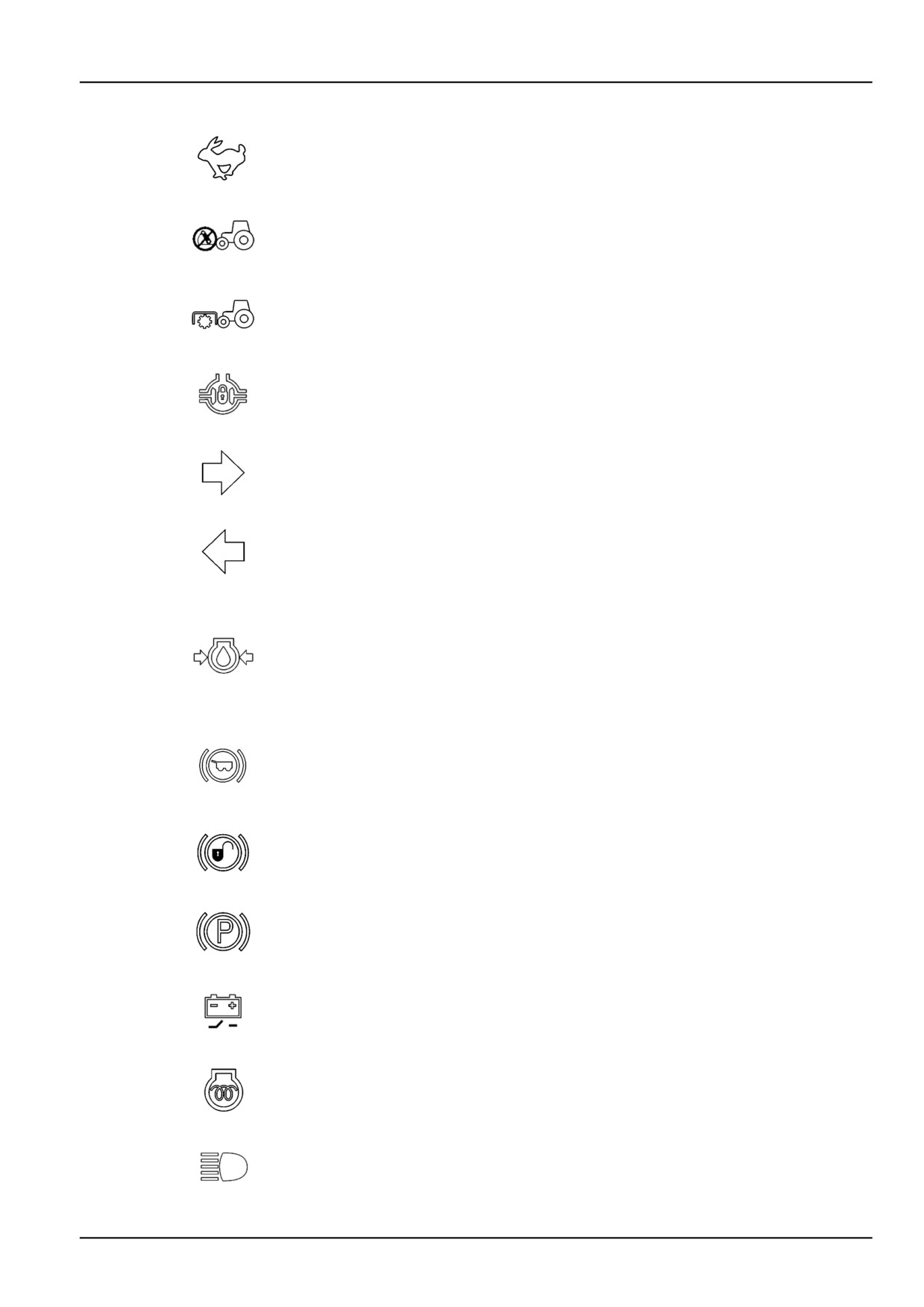
High (HI) gear range indicator light (green)
8
Lights up when the high gear range is selected (tractors with Power-Shuttle/Dual
Command (2 Speed Power Shift) transmission only).
Front lift (amber)
9
This warning light comes on when the front lift is deactivated, or it briefly illuminates
when starting the engine (even if the tractor is not equipped with the front lift).
Front power take-off (amber)
10
This warning light comes on when engaging the front power take−off (if installed).
Differential lock (amber)
11
Lights up when the differential lock is ON.
Right direction indicator (green)
12
The indicator light flashes together with the tractor's right direction indicators.
Left direction indicator (green)
13
The indicator light flashes together with the tractor's left direction indicators.
Engine oil pressure (red)
This warning light should go out a few seconds after starting the engine. If the light stays
on when the engine is running, switch off the engine and find the cause of the problem.
14
If the light remains on, particularly when the tractor is moving, contact your dealer. When
the engine is warmed up and idling, with the tractor stationary, the warning light may
illuminate even if no faults are present.
Trailer brakes (red)
This warning light illuminates when, with the engine running, the tractor's brakes are
15
applied with the respective paired pedals for driving and transport on roads. The warning
light comes on every time the hand brake is applied or there is low brake fluid pressure.
16
Not used
Handbrake (red)
17
This warning light signals that the hand brake is on (with the key start switch ON). It
flashes with the start switch in the STOP position and the hand brake off.
Battery cut-off switch warning light (amber)
18
This indicator light comes on when the battery cut-off switch is on.
Cold start aid (grid heater) (amber)
19
Lights up when the grid heater (thermostarter) is turned on by the key start switch.
Full−beam headlights (blue)
20
This indicator light comes on when the tractor lights are switched to main beam.
3-17
3 - CONTROLS/INSTRUMENTS
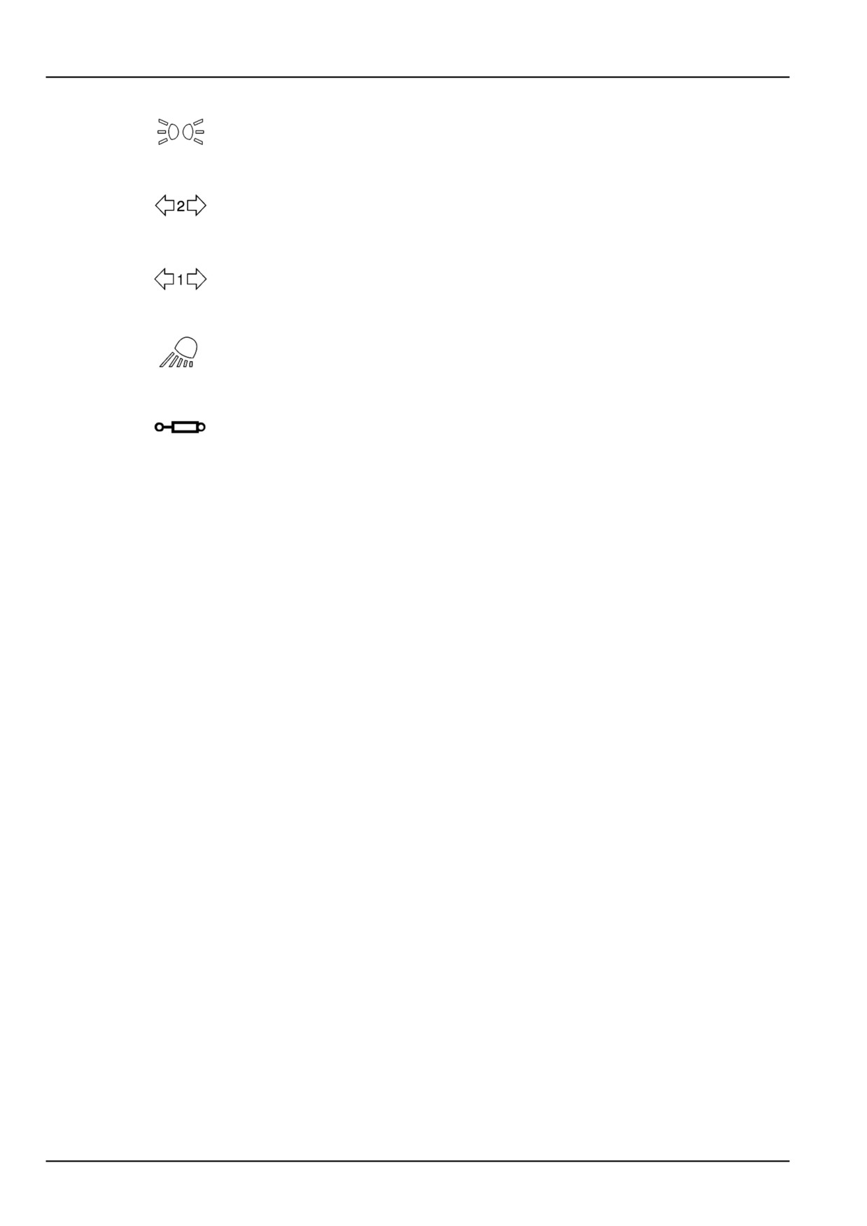
Side lights (green)
21
This warning light comes on when the position lights are switched on.
Second trailer direction indicators indicator light (green)
22
This indicator light flashes together with the tractor/trailer direction indicators, if the
second trailer is connected.
First trailer direction indicators indicator light (green)
23
This indicator light flashes together with the tractor/trailer direction indicators, if the
second trailer is connected.
Work lights (amber)
24
This indicator light comes on when the work lights are switched on (models with cab
only).
Electronic side distributors indicator light (green)
25
This indicator light comes on when the side distributors are operated.
3-18
3 - CONTROLS/INSTRUMENTS
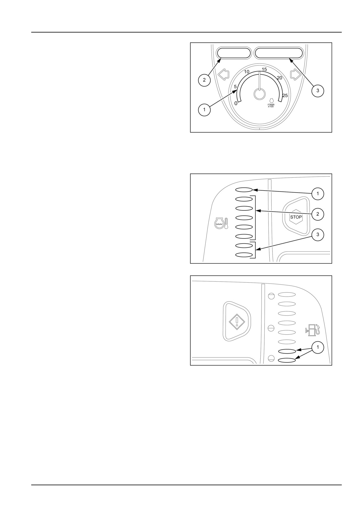
Tachometer/rev-counter (1)
Engine rev counter. To obtain the engine rpm, multiply the
number indicated by the pointer by 100.
Digital display (2)
When the engine switches on, the digital display passes
automatically to show the tractor ground speed, in km/h
or MPH, depending on the set unit of measurement.
Digital display (3)
MOIL13TR00485AA
3
• Rear PTO speed (displayed automatically on starting
the engine).
• Clock.
• Rear lift position.
Engine temperature displays
1. Red area = engine overheating.
In this case, slow the engine to idling speed (without
stopping the engine) and, if the light stays on, have the
cooling system checked.
2. Green area = normal temperature.
3. Blue area = temperature too low.
MOIL13TR00486AA
4
Fuel gauge
Shows the fuel level in the tank. When the tank is full, all
the sections are illuminated. Whereas if the two bottom
sections (1) remain illuminated it means that the fuel level
is below 1/4 (reserve).
MOIL13TR00487AA
5
3-19
3 - CONTROLS/INSTRUMENTS
Multi-function display
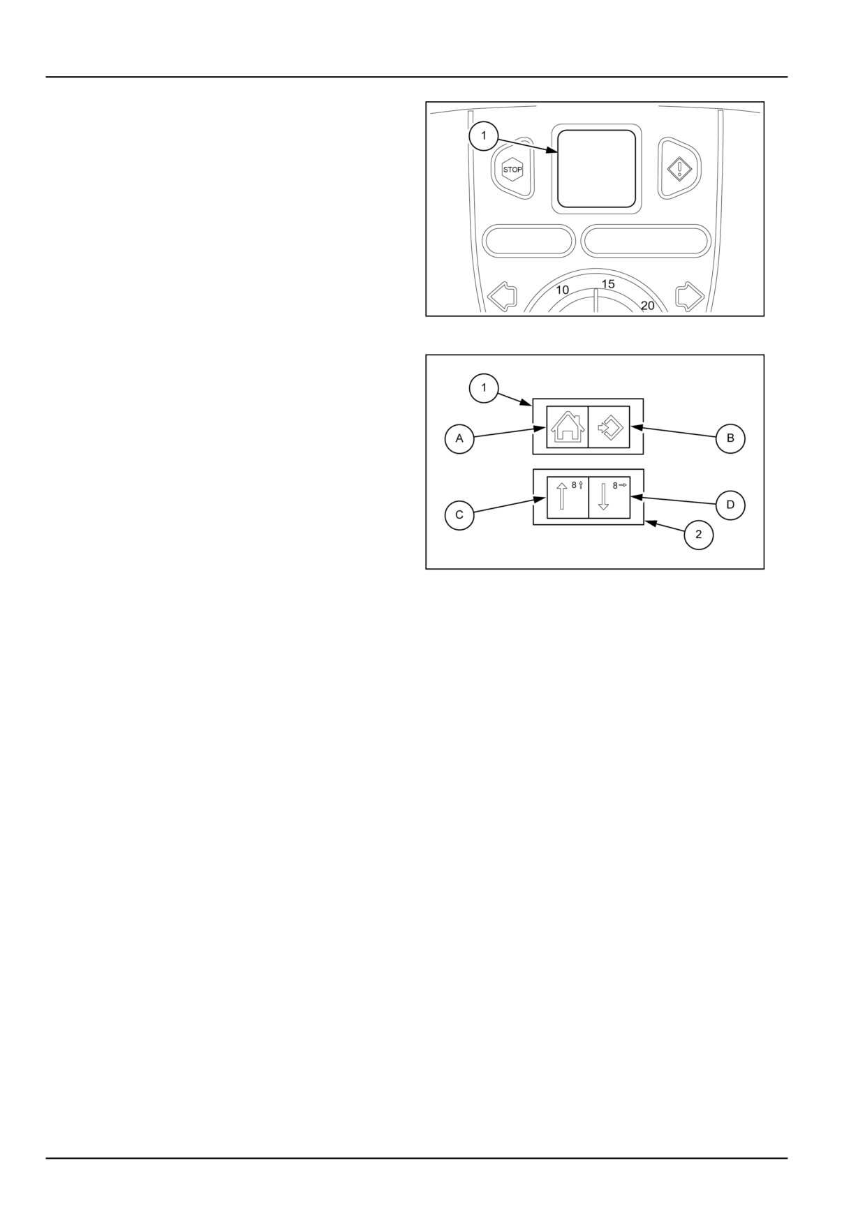
The liquid crystal multi-function display (1) can show use-
ful and necessary information for the driver and a menu
that supports the following setting functions:
• Tractor ground speed calibration
• Instrument cluster dimming
• Buzzer on/off on pressing the buttons
• Speed indication selection in km/h or MPH
• Time display setting with 12 or 24 hour format
MOIL13TR00488AA
6
• Error code presentation.
The menu is navigated through by using the rocker
switches (1) and (2). Each switch has two control po-
sitions, depending on the side on which it is pressed.
To access the SETUP MENU, turn the key start switch
ON and keep the switch (1) pressed for more than three
seconds in position (B).
Switch (1)
(A) Exit/Cancel. Use this button (and that means this
switch position) to cancel or quit the setting and program-
ming modes.
(B) Return = See the MENU/RETURN or confirm button.
MOIL13TR00489AA
7
Press this key to select the programming setting and set-
ting confirmation mode.
Switch (2)
(C) Up arrow = scrolling up through the menu or numerical
value. Press this button (and that means this switch posi-
tion) repeatedly to scroll forwards in the menu or change
the value of a number.
(D) Down arrow = scrolling down through the menu or
numerical value. Press this button (and that means this
switch position) to scroll backwards in the menu or to
move to the right of a position.
3-20
3 - CONTROLS/INSTRUMENTS
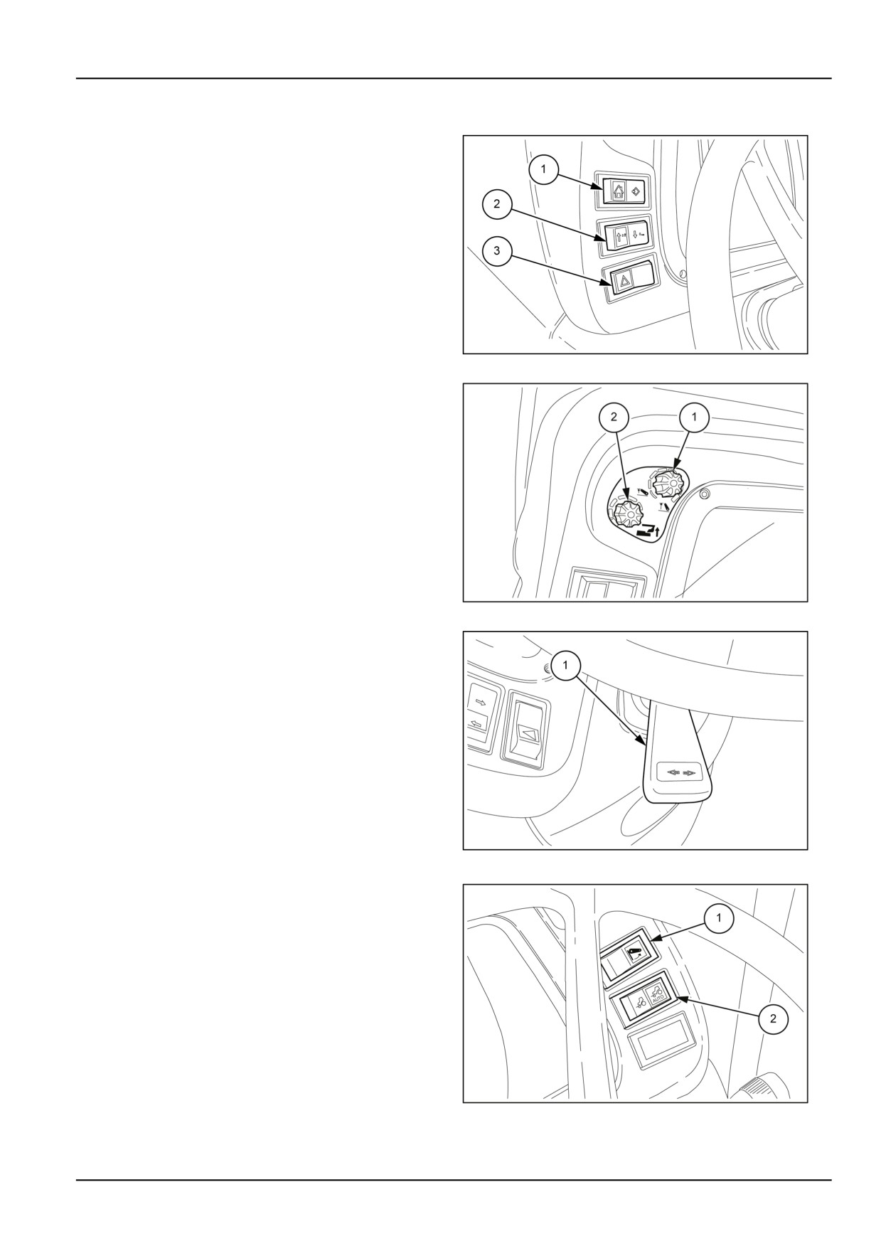
Front controls
1. Menu navigation button
2. Scroll and selection button
3. Hazard lights switch
Press the left side (with the symbol) of the switch (3)
to turn on the hazard light flashers; when pressed, the
switch starts blinking. The panel light flashes at the
same time as the direction indicators.
MOIL13TR00501AA
1
Potentiometers for selecting the functions of
the front lift
Version with cab and SuperSteer™ axle
1. Arm lifting limit adjustment control.
2. Working depth control potentiometer.
MOIL13TR00796AA
2
Power shuttle (Electro-hydraulic shuttle con-
trol lever)
1. The shuttle lever (1), located to the left of the steering
wheel, is used to select forward or reverse when a gear
ratio is engaged.
To select the drive direction, lift the lever and move
it forward for forward drive, or backward for reverse
drive. Drive direction can be selected without pressing
down the clutch pedal.
To change the drive direction keep the lever raised
and move it either forwards or backwards. Drive direc-
tion can be changed without pressing down the clutch
pedal.
MOIL13TR00505AA
3
1. Switch to raise/lower front lift
This switch is used only to lower or raise the implement
at each headland.
2. Four−wheel drive electro-hydraulic control switch.
Front-wheel drive increases the tractor's grip on the
ground; the advantages are evident when working on
uneven, muddy or slippery ground, when ploughing or
working in difficult conditions.
MOIL13TR00788AA
4
3-21
3 - CONTROLS/INSTRUMENTS
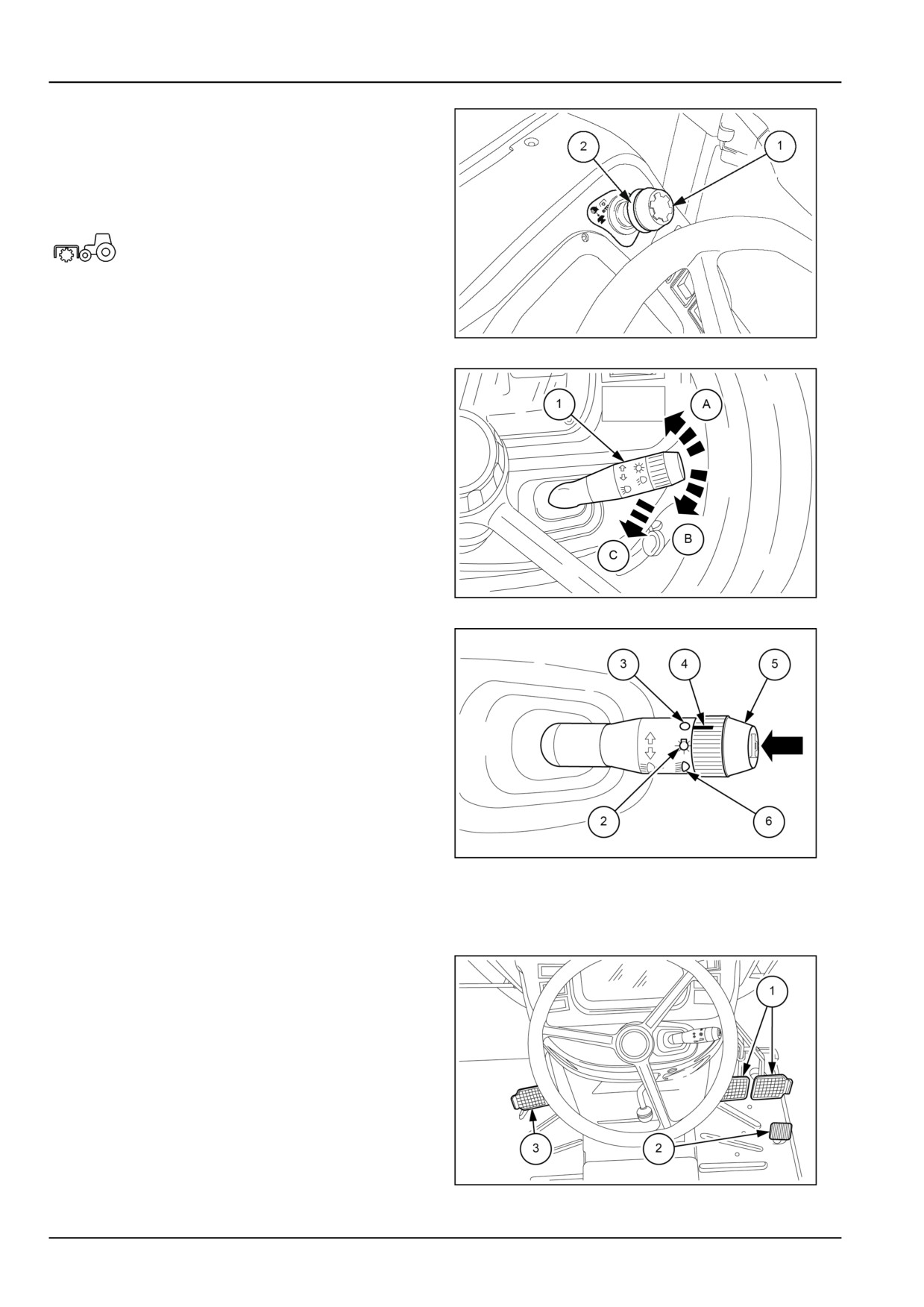
Front power take−off
NOTE: Only for models with SuperSteer™ axle
To engage the power take−off, lightly press the knob (1)
and raise the collar (2).
The warning light on the instrument
cluster will come on to signal the PTO has
engaged.
To disengage the PTO, simply press the knob (1) down-
wards.
MOIL13TR00798AA
5
Direction indicators
To indicate turning to the left, push the stalk (1) forward to
position (A). To indicate turning to the right, pull the stalk
back to position (B).
Flashing lights
With the lights off or dipped, pull the stalk upwards into
position (C) to flash full beam lights. When the lever is
released, it automatically returns to its original position.
MOIL13TR00503AA
6
Side lights
Turn the knob (5) to set the pointer (4) onto the symbol (2).
The position lights/taillights and instrument cluster lights
will come on.
Dipped beam headlights
Move the mark (4) on the knob (5) onto the symbol (6).
Horn
To sound the horn, press the button on the tip of the stalk
(5), as shown in the figure.
MOIL13TR00504AA
7
NOTE: When the mark (4) on the knob is aligned with
symbol (3), all the lights are off. Only the direction indica-
tors and the horn are still functional.
Pedal controls
1. Brake pedals.
2. Foot throttle.
3. Transmission clutch pedal.
MOIL13TR00542AA
8
3-22
3 - CONTROLS/INSTRUMENTS
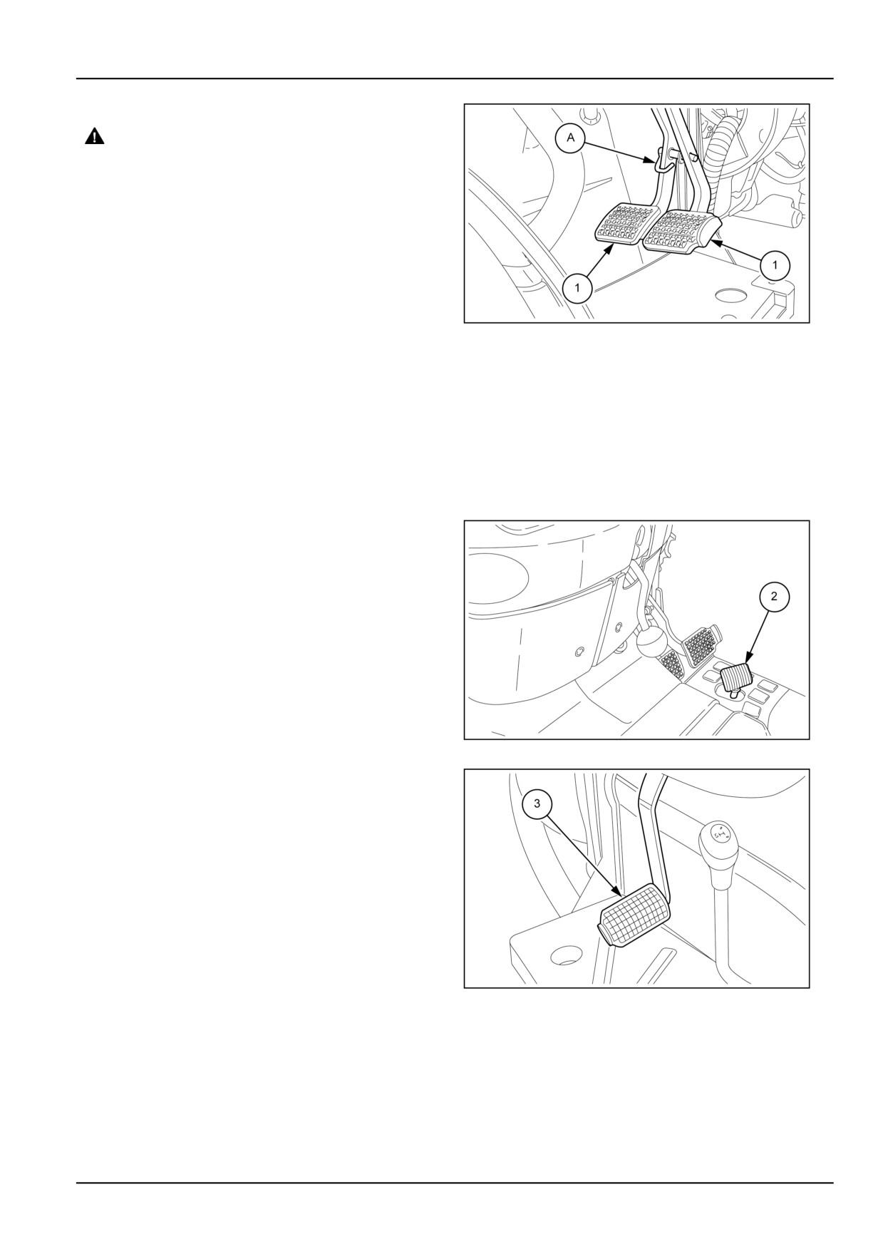
Footbrakes
WARNING
Loss of control hazard!
Uneven brake force exists on left-hand and
right-hand brakes. Always use brake pedal
coupler when traveling on public roads to en-
sure brakes are actuated together.
Failure to comply could result in death or se-
rious injury.
W0081A
The brakes can be operated independently ONLY to facil-
itate manoeuvres in confined spaces.
MOIL13TR00507AA
9
NOTICE: When travelling on the road and towing trailers
with hydraulically operated brakes, always join the brake
pedals (1) together using the pin (A), as shown in the fig-
ure.
NOTE: On four-wheel drive models, front axle transmis-
sion is automatically engaged when the brakes are ap-
plied on all four wheels. With automatic engagement of
4WD, the brakes function much more efficiently, therefore
care must be taken when braking sharply.
Foot throttle
The foot throttle (2) may be used independently of the
hand throttle to control the speed of the tractor. It is rec-
ommended that you use the foot throttle when driving on
the highway.
NOTE: When the foot throttle is released, engine speed
will reduce to the level set by the hand throttle. When
using the foot throttle, set the hand throttle onto the idle
speed position.
MOIL13TR00508AA
10
Transmission clutch pedal.
When the clutch pedal (1) is pressed on models with me-
chanical transmissions, drive is disengaged and the gear
ratio, range and forward or reverse travel can be selected.
On models fitted with the Power Shuttle electro-hydraulic
reverser, the clutch pedal is used to gradually transfer en-
gine horsepower to the driving wheels when starting to
move from a standstill.
NOTICE: Before starting the engine, fully depress the
clutch pedal (1).
NOTE: To prevent premature wear of clutch components,
do not use the clutch pedal as a foot rest.
MOIL13TR00509AA
11
3-23
3 - CONTROLS/INSTRUMENTS
1. Power take−off engagement lever.
To activate the power take−off, engage the clutch by
setting the respective control lever (1) in the com-
pletely raised position.
MOIL13TR00540AA
12
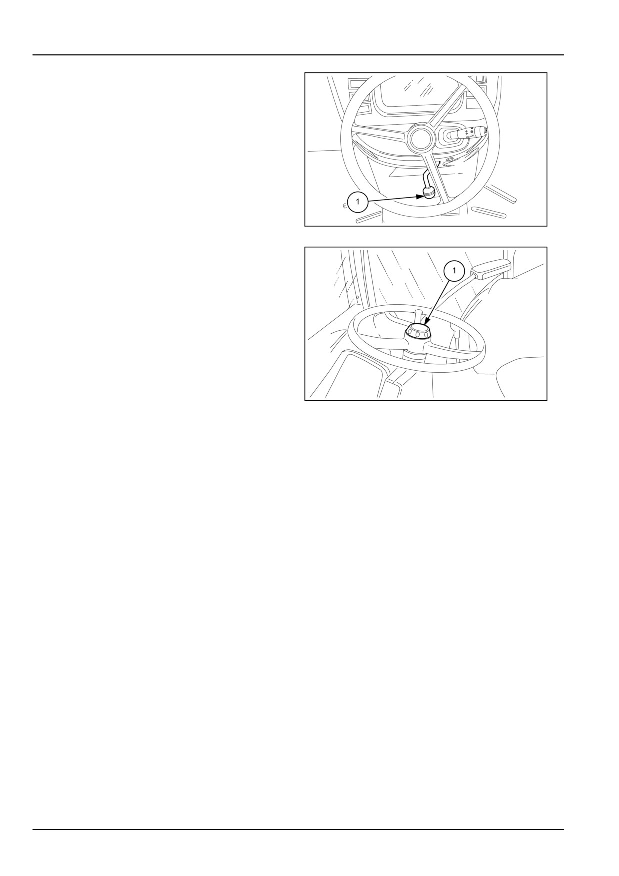
Adjusting the steering wheel
The steering wheel is fitted with a height adjustment knob.
To adjust, loosen the knob (1) and move the steering
wheel to the desired height. Then screw the knob (1) back
on to lock the steering wheel in position.
MOIL13TR00541AA
13
3-24
3 - CONTROLS/INSTRUMENTS
LEFT-HAND SIDE CONTROLS
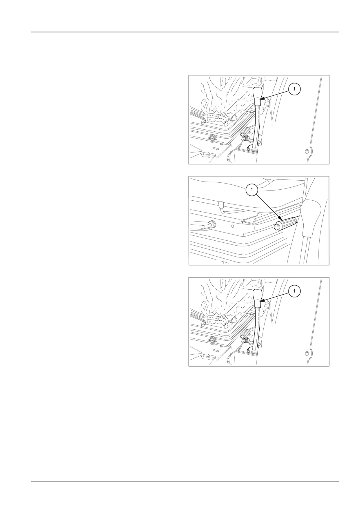
Console Left-hand console - Control identification
1. Shuttle (mechanical shuttle control lever)
NOTE: On the dual command (2 speed power shift)
version of the Power Shuttle the lever (1) governs en-
gagement/disengagement of the parking brake.
MOIL13TR00998AA
1
Handbrake
To apply the handbrake, press the red button on the end of
the lever (1) and pull upwards. The handbrake should lock
on the third catch of the ratchet. If the handbrake exceeds
the third catch it will need to be adjusted, as described in
Chapter 7 "Maintenance". To release the handbrake, pull
the lever slightly upwards, press the red button and then
fully lower the lever.
NOTICE: Whenever leaving the tractor switch off the en-
gine and apply the handbrake.
MOIL13TR00513AA
2
Shuttle (mechanical shuttle control lever)
The lever (1) is used to select forward or reverse when a
gear ratio is engaged. To select the drive direction, move
the lever (1) forwards, for forward drive, or backwards, for
reverse, as shown on the knob of the lever. Slow down
almost until stopping before reversing direction when the
tractor is in motion.
NOTE: To start the engine, set the shuttle lever (1) on the
central neutral position. In addition, it is recommended to
press the clutch pedal fully down.
MOIL13TR00998AA
3
3-25
3 - CONTROLS/INSTRUMENTS
Parking brake for hydraulic transmissions
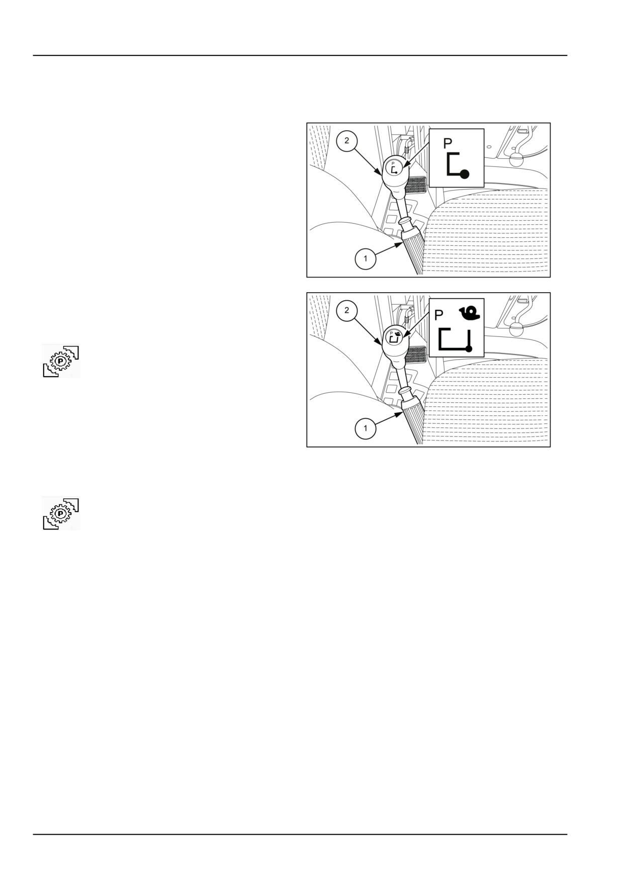
Parking lock
NOTICE: On models with Power Shuttle and HI-LO when
leaving the machine, besides applying the hand brake you
must engage the parking brake Parking lock .
Figure 1 configuration with HI-LO , Power shuttle.
Figure 2 configuration with HI-LO , Power shuttle and
creeper unit.
Besides the hand brake (1) there is the parking brake con-
trolled by the lever (2). Its operation is as follows:
Engagement
MOIL13TR00956AA
1
With the tractor stationary, move the lever from the central
neutral position on the left, then forwards in the direction
(P) and subsequently to the right as shown on the plate
on the lever.
To check proper engagement, engage a
gear and a direction and then try moving:
the following warning light will come on,
accompanied by a sound signal, to indicate
correct engagement.
Disengagement
Before setting off with the tractor it is necessary to dis-
engage the brake. With the tractor stationary, move the
MOIL13TR00957AA
2
lever to the left, then backwards as shown on the plate on
the lever.
If the warning light stays on and there is a
sound signal while moving, it means that
the brake has not been disengaged and
therefore do not try moving the machine.
3-26
3 - CONTROLS/INSTRUMENTS
RIGHT-HAND SIDE CONTROLS
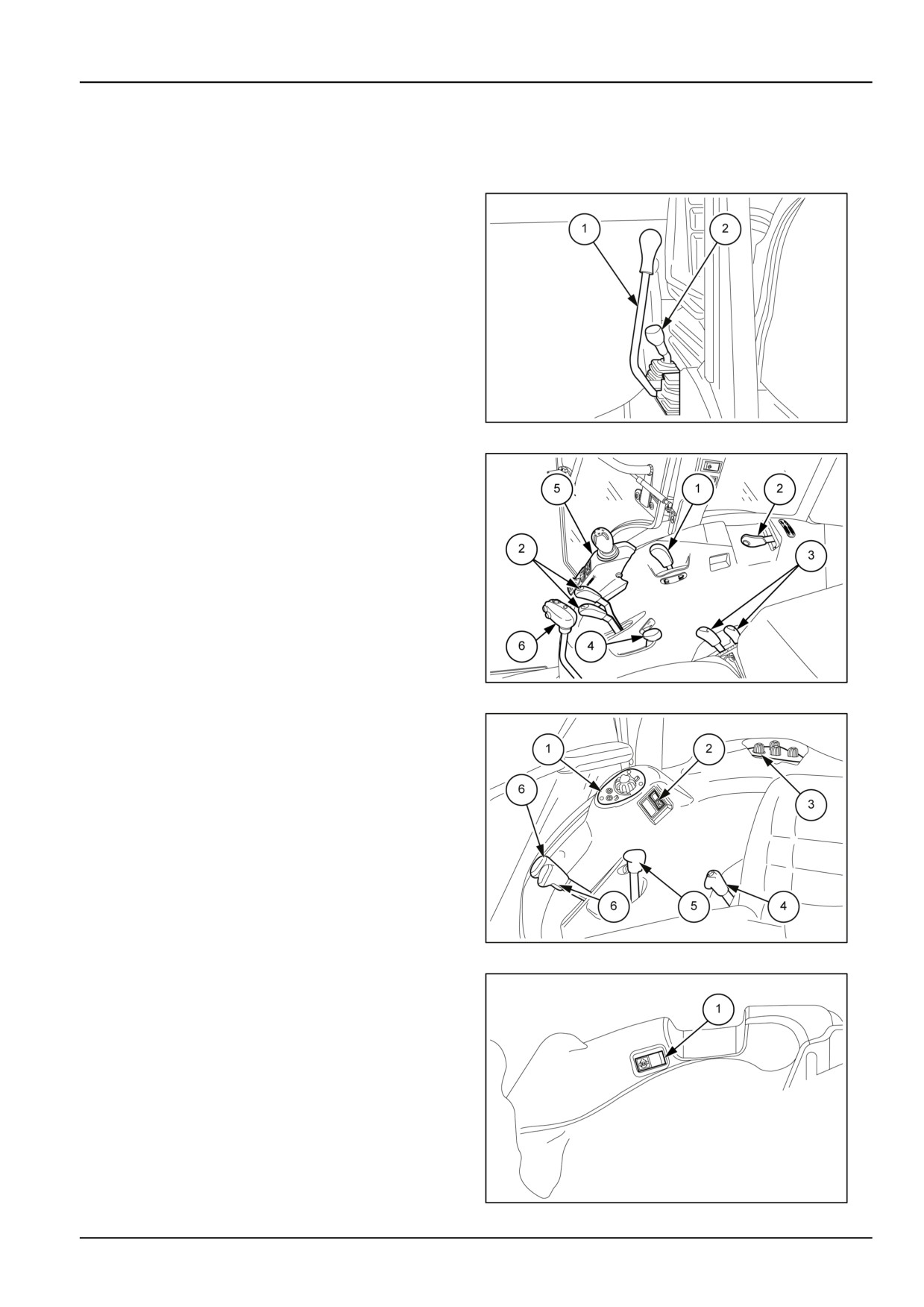
Console Right-hand console - Control identification
1. Gear lever.
2. Range gear lever.
MOIL13TR00799AA
1
Version with mechanically-operated lift
1. Lift-O-Matic™ - Mechanically-operated hydraulic lift.
2. Auxiliary control valve levers.
3. Hydraulic lift control levers.
4. Hand throttle lever; regulates engine RPM. Press it
forward to increase the engine RPM, pull it backwards
to decrease the speed.
5. Controls for side electro-hydraulic distributor opera-
tion.
6. Gear lever.
MOIL13TR00373AA
2
Version with electronically-operated lift
1. Lower arms up/down adjustment knob
2. Fast raise/lower switch rear lift
3. Hydraulic lift controls
4. Auxiliary control valve levers
5. Hand throttle lever; regulates engine RPM. Press it
forward to increase the engine RPM, pull it backwards
to decrease the speed.
6. Auxiliary control valve levers
MOIL13TR00795AA
3
Electrohydraulic differential lock
Version without cab
1. Differential Lock Switch
MOIL13TR00860AA
4
3-27
3 - CONTROLS/INSTRUMENTS
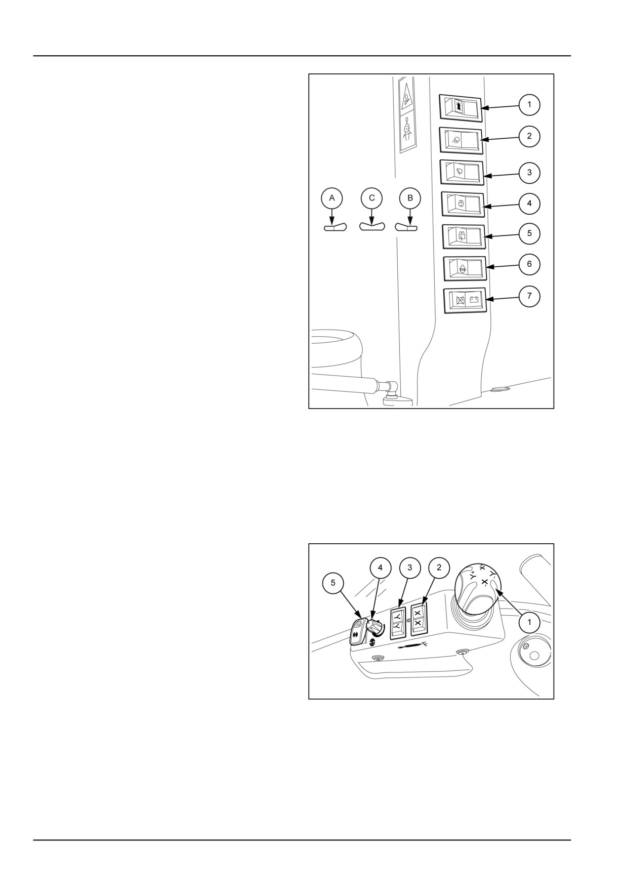
(1) Rotating beacon switch
• Position (A) = beacon on.
• Position (B) = beacon off.
(2) Work lights switch
• Position (A) = front and rear work lights on.
• Position (C) = rear work lights on, front work lights off.
• Position (B) = work lights off.
(3) Front windscreen wiper switch
• Position (A) = second speed.
• Position (C) = first speed.
• Position (B) = off.
(4) Front windscreen washer switch
• Position (A) = windscreen washer on.
On release, the switch will return to the off position.
(5) Rear window washer switch
• Position (A) = rear washer on; when released, the
switch returns to position (C).
• Position (C) = rear wiper on.
• Position (B) = off.
MOIL13TR00303BA
5
(6) Electrohydraulic differential lock
• Position (A) = on. When released the switch returns to
position (C)
• Position (B) = off.
(7) Battery cut-off button
• Position (A) = battery cut off from the electric system.
• Position (B) = battery connected to the electric system
Electro-hydraulic distributor controls
Available only for cab models, they are located on the
right mudguard.
1. Joystick for side distributor operation
2. Distributor activation switch on line X
3. Distributor activation switch on line Y
4. Potentiometer for oil flow control to the hydraulic mo-
tor.
5. Hydraulic motor ON/OFF switch
MOIL13TR00380AA
6
3-28
3 - CONTROLS/INSTRUMENTS
REARWARD CONTROLS
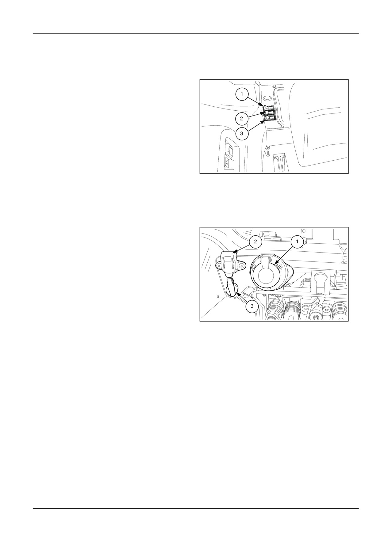
Console - Control identification
Switches governing stabilizers and right
hand lift rod
1. Switch governing right−hand lift rod adjustment
2. Push−button governing right and left hydraulic stabi-
lizer extension.
3. Push−button for locking hydraulic stabilizers
MOIL13TR00999AA
1
EXTERIOR CONTROLS
Console - Control identification
1
7 pin power socket 40 A
2
Two pole power socket 25 A
3
One pole power socket 8 A
MOIL13TR00377AA
1
3-29
3 - CONTROLS/INSTRUMENTS
DISPLAY SETTINGS
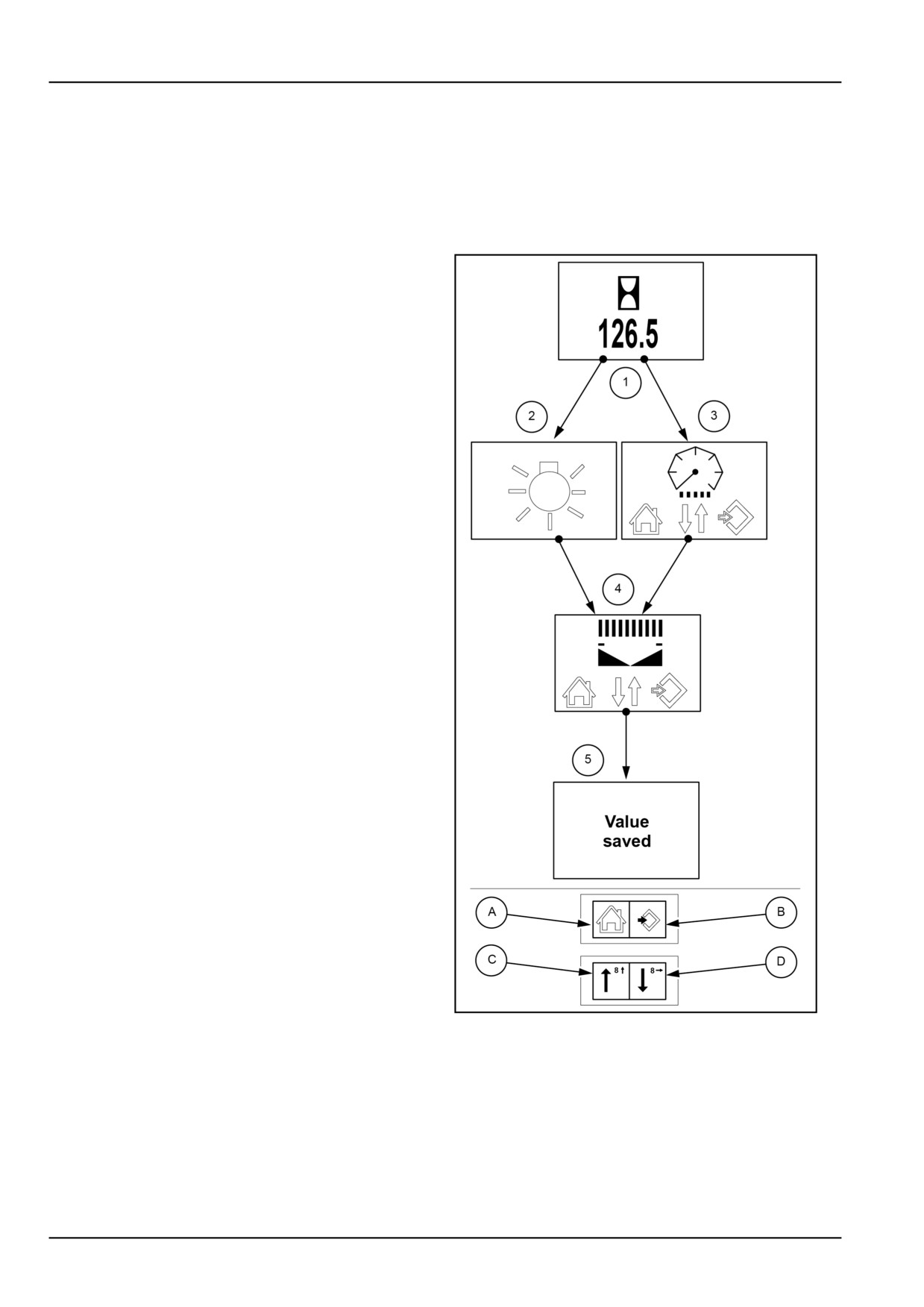
Instrument cluster - Program
Information display or indicator brightness
calibration
If you want to change the instrument’s brightness,
starting from the display (1), proceed as follows:
• Turn the ignition key onto the first click, press the arrow
(C) on the switch for at least 3 seconds and the display
will show a symbol as in detail (2), to change the bright-
ness of the indicators, or the arrow (D) to view the detail
(3) to change the brightness of the liquid crystal display
• To change the brightness of the indicators, press and
release the arrow (C) on the switch or to change the
brightness of the information display, press and release
the arrow (D) on the switch. In both cases the display
will show a symbol as in detail (4).
• Now press the arrow (D) on the switch to decrease the
brightness or the arrow (C) to increase it.
• Press the symbol (B) again to save the set brightness
level and after approximately 2 seconds the display
must show “Value saved”, as in detail (5).
NOTE: If you want to stop the display, press the symbol
(A)to exit the programming menu.
When starting to change the brightness with the arrows,
each time they are pressed, both the brightness and de-
creasing or increasing the number of bars of the diagram
of detail (4) must change at the same time.
MOIL13TR00556CA
1
3-30
3 - CONTROLS/INSTRUMENTS
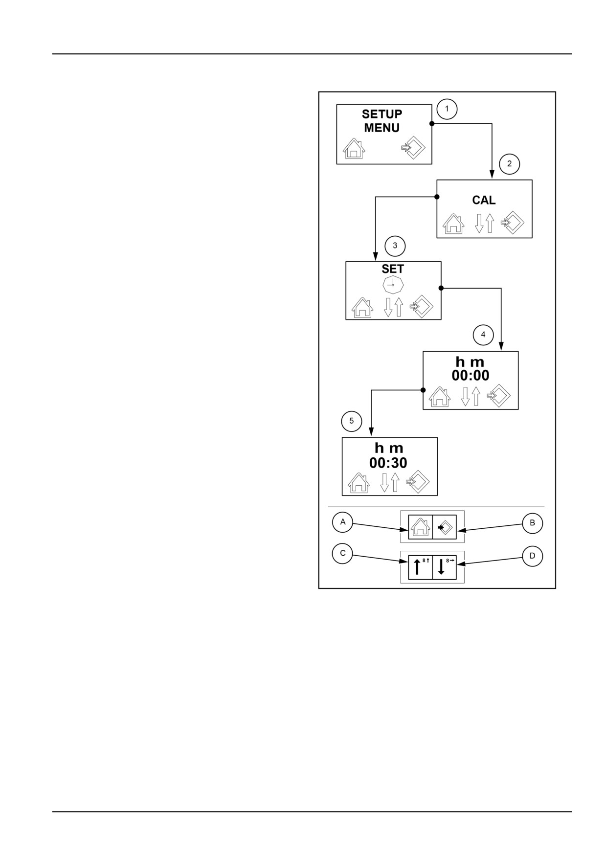
Changing clock hours/minutes
If you want to change the hour, proceed as follows.
Turn the ignition key onto the first click, holding down the
symbol (B) on the switch for more than three seconds.
• The central display shows "SETUP MENU" as in detail
(1). Release the symbol (B) to go to detail (2) "CAL".
• Press the symbol (B) on the switch to go to the display
“SET” as in detail (3).
• Press the symbol (B) on the switch again and you dis-
play the hour set at that time with the first digit of the
hours “h” blinking. Clock setting can now begin.
• Use the arrow (C) on the switch to change the value
that increases by one unit each time it is pressed.
NOTE: If you hold down the switch continuously with-
out releasing it, the digit will move forward continuously
to 12 and recommence from 0, if the setting has been
made in the 12 hour mode, or up to 24 to recommence
from 0 if vice versa it has been made in the 24 hour
mode.
• To save the setting, press the switch on the symbol (B).
• Use the arrow (D) to move to the right. If you want to
change, repeat the instructions just described or press
the arrow down again, to move to the right. Repeat the
same steps until the last digit of minutes “m”. See the
example in detail (5).
• To save, press the switch on the symbol (B).
NOTE: If you want to stop the display, press the symbol
(A) on the switch. This will automatically take you back to
the display as in detail (4). Press the same symbol again
to exit the programming menu.
MOIL13TR00555CA
2
3-31
3 - CONTROLS/INSTRUMENTS
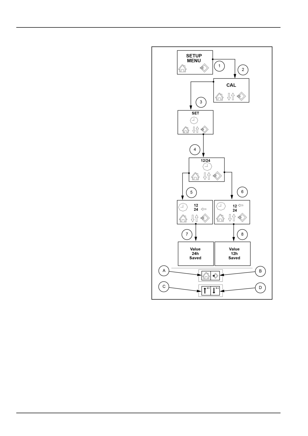
Changing 12 or 24 hour clock format
If you want to display the set time in 12 or 24 hour mode,
follow these instructions:
Turn the ignition key onto the first click, holding down the
symbol (B) on the switch for more than three seconds.
• The central display shows “SETUP MENU” as in detail
(1). Release the symbol (B) to go to detail (2) CAL.
Press the arrow (D) to reach the word “SET” as on the
screen of detail (3).
• Press the arrow (C)or (D) and the display will show “12/
24” as in detail (4).
• Press the symbol (B) and the display will show the last
setting made, with one arrow in the direction of 12 or
24 as shown in details (5) and (6). If you want to stop
the selection, press the symbol (A)on the switch to go
back automatically to the view as in detail (4). Press
the same symbol again to exit the programming menu.
If you want to proceed, press the arrow (C) on the switch
to pass from “24” to “12” or on the arrow (D) to pass
from “12” to “24” as shown in details (7) and (8).
• In both cases, press the symbol (B) and the display will
show the selection blinking, as shown in details (7) or
(8). Wait approximately two seconds to save the set-
ting. the blinking will stop to confirm saving.
MOIL13TR00554CA
3
3-32
3 - CONTROLS/INSTRUMENTS
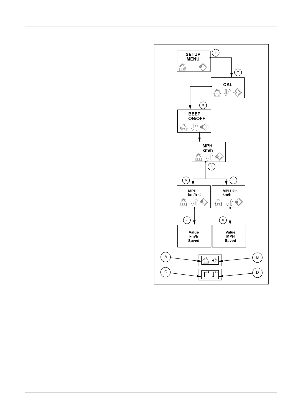
Changing unit of measurement
If you want to turn audible warning on or off each time a
button is pressed, proceed as follows:
Turn the ignition key onto the first click, holding down the
symbol (B) on the switch for more than three seconds.
• The central display shows “SETUP MENU” as in detail
(1). Release the symbol (B) to go to detail (2) (CAL).
• Now press the arrow (D) on the switch and the display
will show the screens in sequence as illustrated in de-
tails (2) and (3).
• From viewing the detail (3) press the arrow (D)again
and the display will show “MPH km/h” as in detail (4).
• Press the symbol (B) and the display will show the last
setting made, “km/h" indicated by the arrow as in de-
tail
(5) or “MPH" indicated by the arrow as in detail
(6). Press on the arrow (C) on the switch to pass from
“km/h” to “MPH” or on the arrow (D) to pass from
“MPH” to “km/h”.
• From the condition of detail (5) press (B) to save ON,
the display will show “Value km/h Saved” as in detail
(7) or from the condition of detail (6) to save OFF, the
display will show “Value MPH Saved” as in detail (8).
NOTE: If you want to stop the display, press the symbol
(A) on the switch. This will automatically take you back
to the display as in detail (4). Press the same symbol
again to exit the programming menu.
MOIL13TR00553CA
4
3-33
3 - CONTROLS/INSTRUMENTS
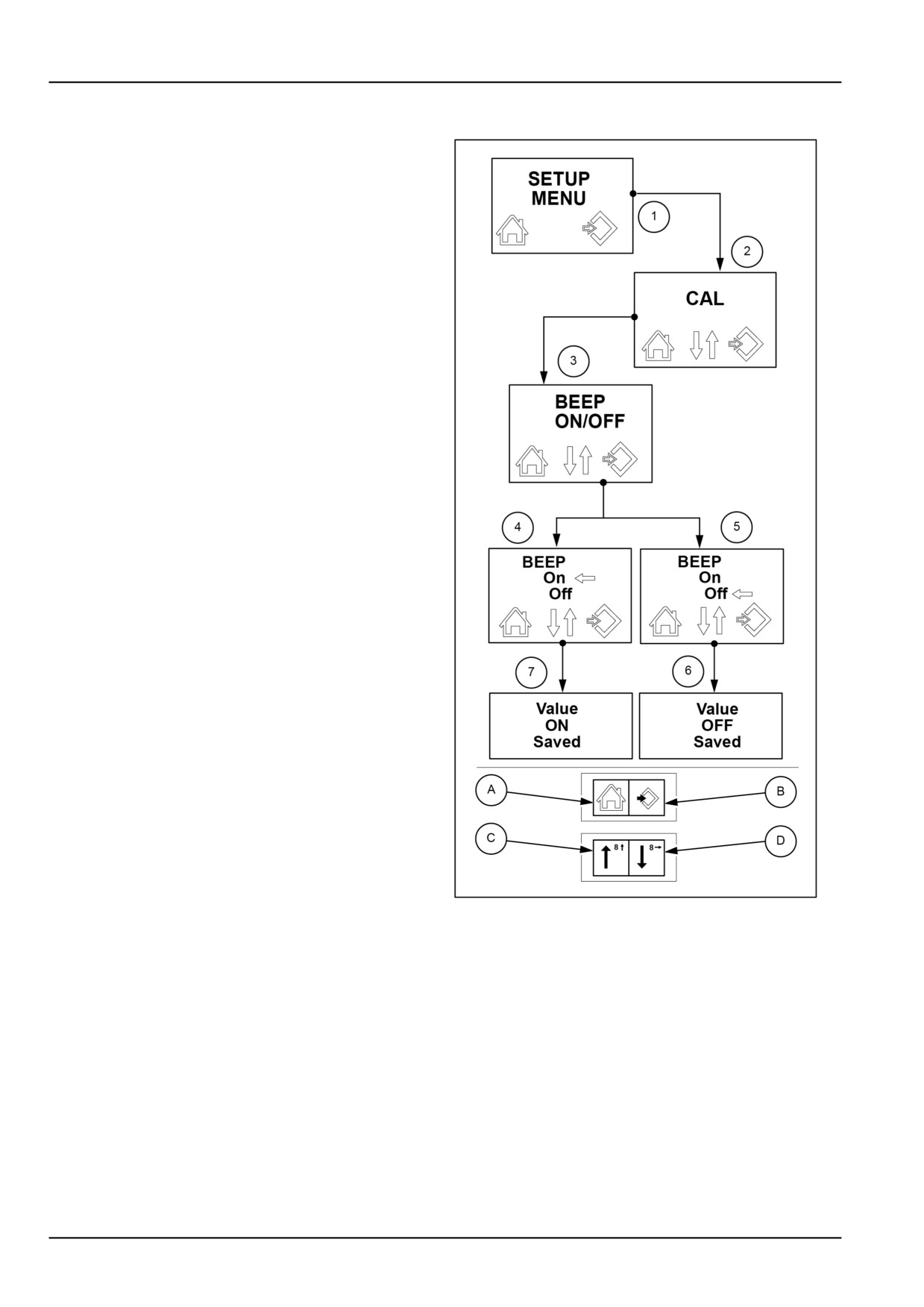
Audible warning ON/OFF
If you want to turn audible warning on or off each time a
button is pressed, proceed as follows.
Turn the ignition key onto the first click, holding down the
symbol (B) on the switch for more than three seconds.
• The central display shows “SETUP MENU” as in detail
(1). Release the symbol (B) to go to detail (2) (CAL).
• Now press the arrow (D) on the switch until the display
shows “BEEP ON/OFF” as in detail (3).
• Press the symbol (B) and the display will show the last
setting made, “BEEP ON” as in detail (4) or “BEEP
OFF” as in detail (5). Press on the arrow (D) on the
switch to pass from “ON” to “OFF” or on the arrow (C)
to pass from “OFF” to “ON” as in details (4) and (5).
• From the condition of detail (4) press (B) to save ON,
the display will show “Value ON Saved” as in detail
(6) or from the condition of detail (5) to save OFF, the
display will show “Value OFF Saved” as in detail (7).
NOTE: If you want to stop the display, press the symbol
(A) on the switch. This will automatically take you back
to the display as in detail (3). Press the same symbol
again to exit the programming menu.
MOIL13TR00552CA
5
3-34
3 - CONTROLS/INSTRUMENTS
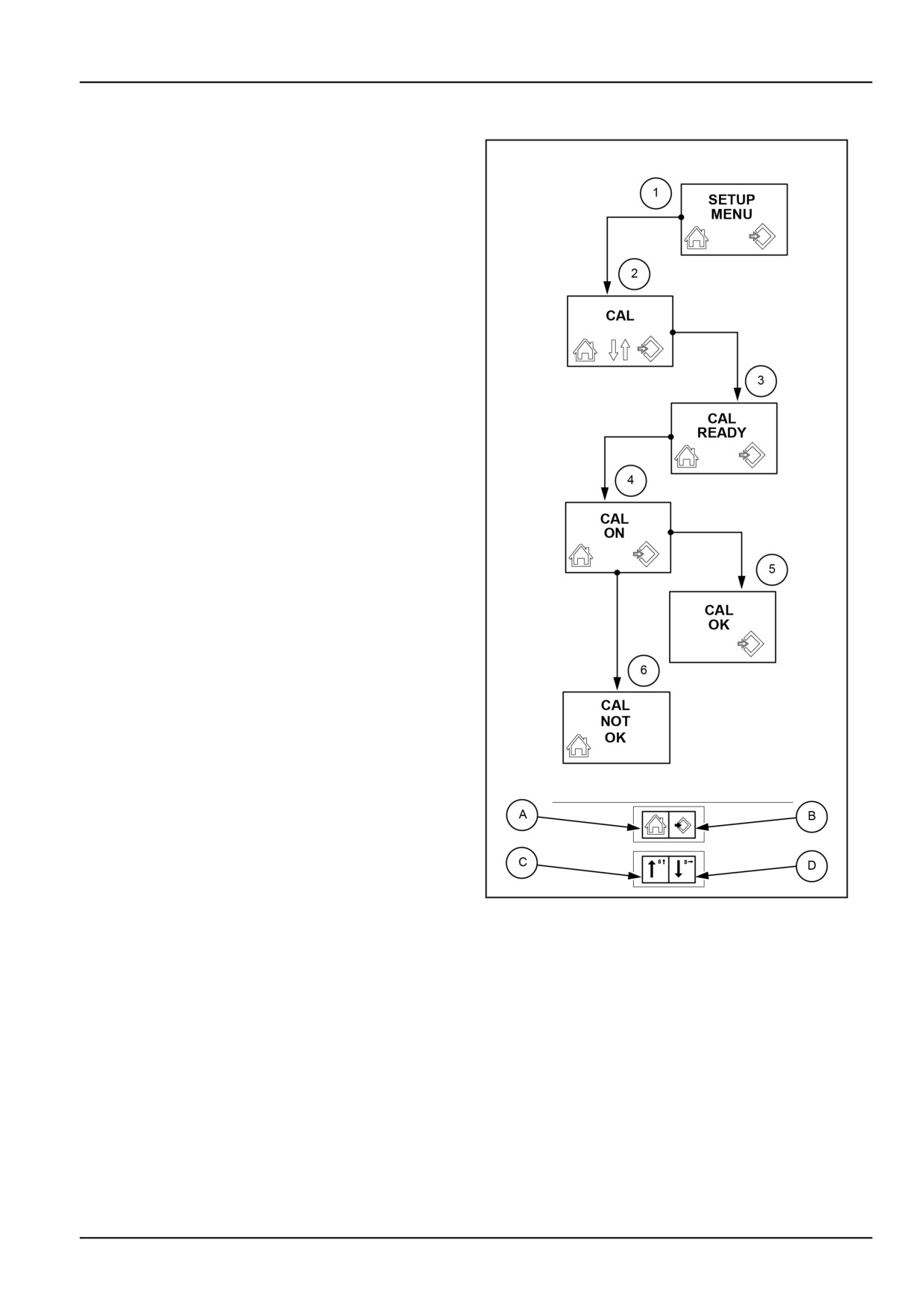
Speed calibration
If rear tyres of a different size are to be fitted, with a dif-
ference in radius of more than 13 mm (0.5 in) compared
to the standard ones, it will be necessary to recalibrate
the electronic control module so as to get the display of a
specific ground speed. For resetting, proceed as follows.
Select a dry, compact and level surface (preferably con-
crete) and measure out a section exactly 100 m (328.1 ft)
long. Mark the start and finish of this measured distance
with a bold chalk line.
Turn the ignition key onto the first click, holding down the
symbol (B) on the switch for more than three seconds.
• The central display shows “SETUP MENU” as in detail
(1). Release the symbol (B) to go to detail (2) (CAL).
• Press the symbol (B) on the switch and the display will
show “CAL READY”, as in detail (3).
• Select a suitable gear and provide a speed above
2 km/h (1.2 mph) and at the start of the line drawn
beforehand, press the pushbutton and the display will
show “CAL ON” blinking, as in detail (4).
NOTE: The ground speed must not drop under 2 km/h
(1.2 mph). If the speed is less than as prescribed, cal-
ibration will stop.
• When the central portion of the front tyres passes over
the end line, press the button on the symbol (B) again
and the display will show “CAL OK” as in detail (5).
Now press the symbol (B) again to save the setting. If
on the contrary the procedure has not been performed
correctly the display will show “CAL NOT OK”, as in
detail 6.
NOTE: If you want to stop the display, press the symbol
(A) on the switch. Press the same symbol again to exit
the programming menu.
MOIL13TR00551CA
6
3-35
3 - CONTROLS/INSTRUMENTS
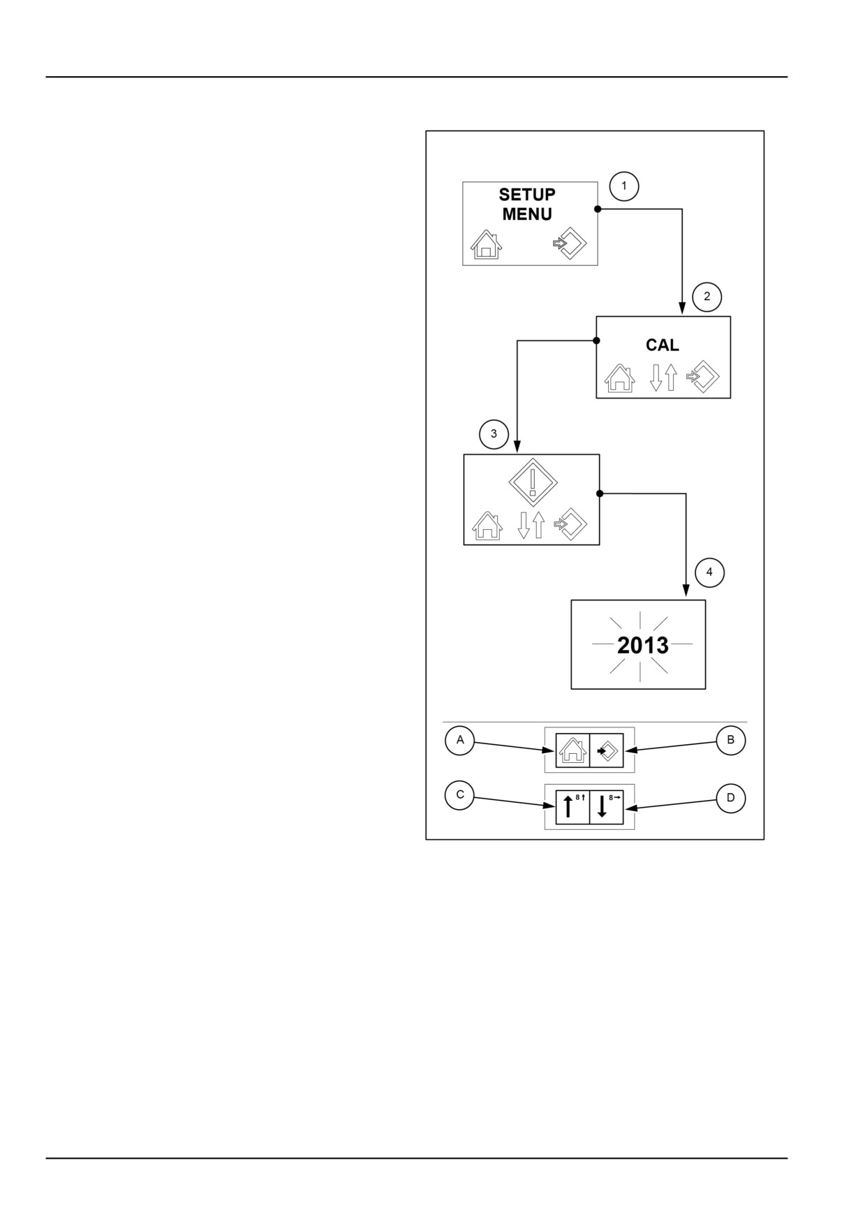
Active fault codes display
If you want to display the active fault codes, proceed as
follows.
Turn the ignition key onto the first click, holding down the
symbol (B) on the switch for more than three seconds.
• The central display shows “SETUP MENU” as in detail
(1). Release the symbol (B) and after approximately
two seconds the display will show “CAL”, as in detail
(2).
• Now press the arrow (C) on the switch to display the
symbol as in detail (3).
• Press the symbol (B) on the switch to display the active
fault codes
NOTE: The current fault codes are displayed in se-
quence. Each code is displayed blinking for 4 seconds
as in detail (4).
If you want to stop the display, press the symbol (A) on
the switch. This will automatically take you back to the
display as in detail (3). Press the same symbol again to
exit the programming menu.
MOIL13TR00550CA
7
3-36
3 - CONTROLS/INSTRUMENTS
TRANSMISSION
Transmission - Operating 4WD models
By adopting different bevel gear pairs, all of the listed mechanical transmissions can develop a speed of 40 km/h
(24.85 mph).
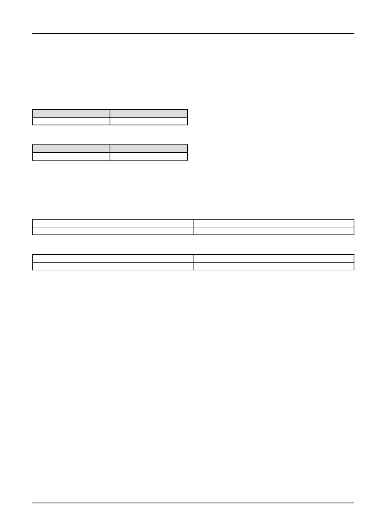
Models with standard front axle:
FRONT
REAR
11/28
11/36
With 20 " rear tires the bevel gear pair for all models is as follows:
FRONT
REAR
10/29
11/32
As a consequence of the use of the high pinion set, the synchronised power take−off has a different ratio between
the wheel speed and the take-off shaft speed.
With the previously noted bevel gear pairs, the new ratios expressed in power take−off per rear wheel revolution, are
listed below:
With all tires except for 380/70 R 20
revs 11.55
PTO 540 RPM
revs 16.23
PTO 1000 RPM
With tire 380/70 R 20
revs 8,09
PTO 540 RPM
revs 12,73
PTO 1000 RPM
NOTE: If the tires are changed, make sure that the new equipment bears the “ A8” code on the side. Always observe
the inflation pressures as specified on tables.
3-37
3 - CONTROLS/INSTRUMENTS
Transmission with gear reducer and mechanical reversing mechanism
30 km/h (18.6 mph) - 40 km/h (24.9 mph) - 16FWD +
16REV
WARNING
Unexpected machine movement!
With the engine running and only the gear
lever in neutral, the machine can engage and
move suddenly if someone accidentally op-
erates this lever. Place all levers in neutral,
disengage the power take-off, lower any im-
plements, and set the parking brake before
exiting the machine. Use wheel chocks when
parking on slopes.
Failure to comply could result in death or se-
rious injury.
W0057B
MOIL13TR00799AA
1
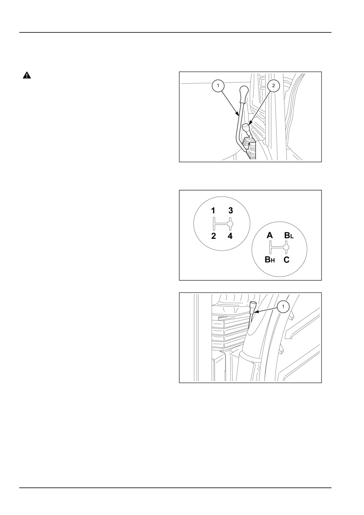
The gear lever (1) selects four gear ratios (1 - 2 - 3 - 4).
The range lever (2) provides four ranges:
A
slow
BL
medium slow
BH
medium fast
C
fast
Separate use of gear levers (1) and (2) fig. 1 and lever (1)
fig. 3 allows 16 forward gears and 16 reverse gears to be
selected.
The tractor must always be stopped to change from one
range to another. To change from one speed to another
within the same range, disengage the clutch and move
the gear lever (the tractor does not need to be stationary
as the gears are synchro−engaged).
MOIL13TR00518AA
2
Mechanical shuttle lever
The lever (1) located to the left of the driver’s seat, is used
to select forward or reverse when a gear ratio is engaged.
To select the direction of travel, move lever (1) forwards
for forward movement or backwards for reverse, as shown
on the top of the gear lever knob. To change direction of
travel whilst in movement, slow down the tractor (almost
to a standstill).
NOTE: In order to start the engine, move the shuttle con-
trol lever (1) to the central neutral position. In addition,
it is recommended to press the transmission clutch pedal
fully down.
MOIL13TR00852AA
3
3-38
3 - CONTROLS/INSTRUMENTS
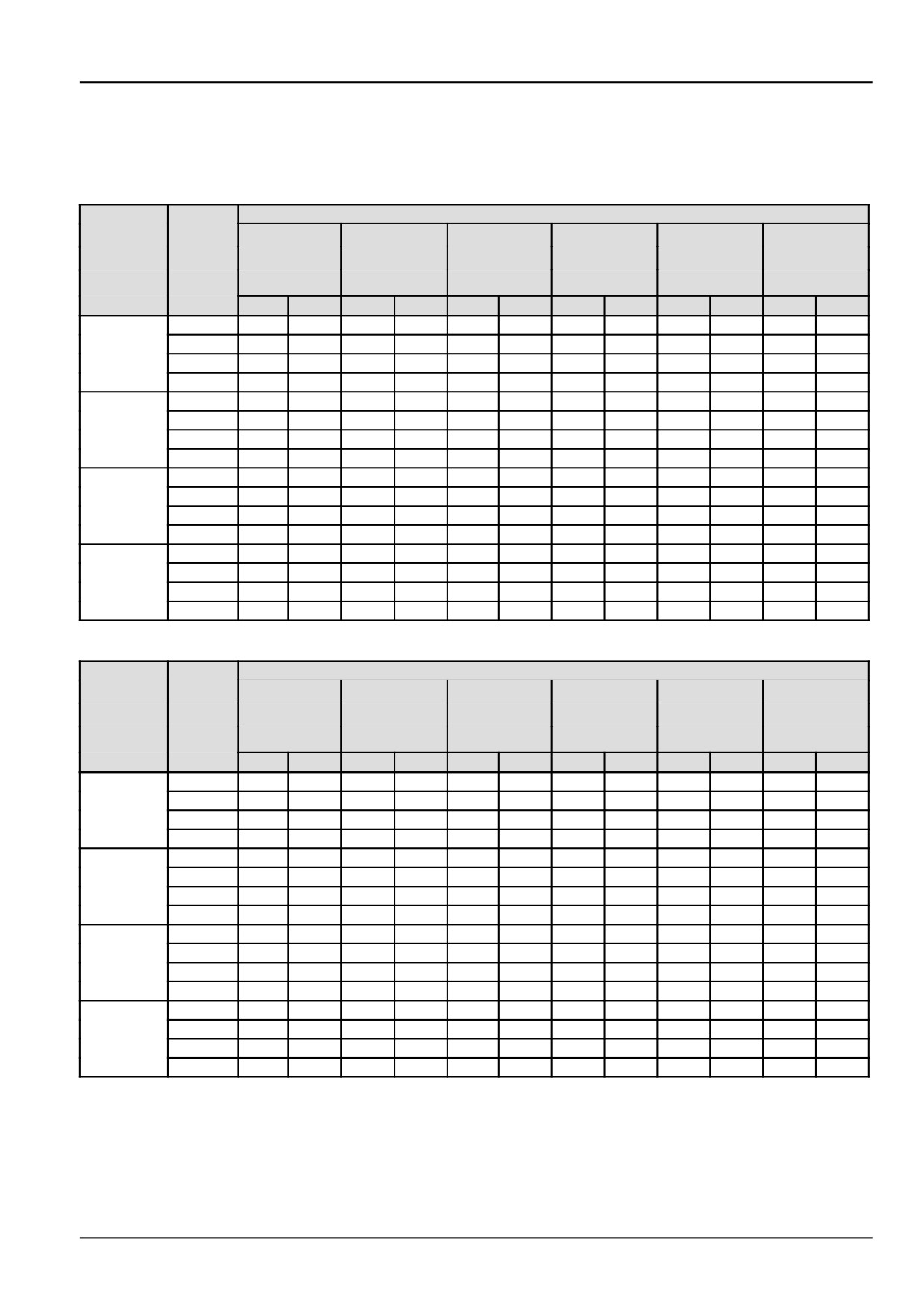
SPEED AT MAXIMUM POWER
Transmission 30 km/h (18.6 mph) version
16 FWD + 16 REV
FORWARD SPEED
REAR TIRES
13.6 R 28
14.9 R 28
340/85 R 28
RANGE
GEAR
380/70 R 20
380/70 R 24
420/70 R 24
380/85 R 28
420/70 R 30
380/70 R 28
420/70 R 28
19.5L - 24
km/h
mph
km/h
mph
km/h
mph
km/h
mph
km/h
mph
km/h
mph
1
0,64
0.40
0,54
0.34
0,57
0.35
0,59
0.37
0,62
0.38
0,64
0.40
2
0,96
0.59
0,81
0.50
0,85
0.53
0,88
0.55
0,92
0.57
0,95
0.59
A
3
1,41
0.87
1,19
0.74
1,24
0.77
1,30
0.81
1,35
0.84
1,4
0.87
4
2,80
1.74
1,77
1.10
1,84
1.15
1,92
1.19
2,0
1.24
2,07
1.29
1
2,69
1.67
2,29
1.42
2,39
1.48
2,49
1.54
2,59
1.61
2,69
1.67
2
4,02
2.50
3,41
2.12
3,56
2.21
3,71
2.30
3,85
2.39
4,0
2.49
BL
3
5,90
3.67
5,01
3.11
5,23
3.25
5,45
3.38
5,67
3.52
5,88
3.66
4
8,75
5.43
7,42
4.61
7,75
4.81
8,07
5.01
8,39
5.22
8,72
5.42
1
3,30
2.05
2,8
1.74
2,92
1.82
3,04
1.89
3,62
2.25
3,29
2.04
2
4,92
3.05
4,17
2.59
4,36
2.71
4,54
2.82
4,72
2.93
4,9
3.04
BH
3
7,23
4.49
6,14
3.81
6,4
3.98
6,67
4.14
6,94
4.31
7,2
4.48
4
10,71
6.65
9,09
5.65
9,48
5.89
9,88
6.14
10,27
6.38
10,67
6.63
1
9,52
5.92
8,08
5.02
8,43
5.24
8,79
5.46
9,14
5.68
9,49
5.90
2
14,19
8.82
12,05
7.49
12,57
7.81
13,10
8.14
13,62
8.46
14,15
8.79
C
3
20,86
12.96
17,71
11.01
18,48
11.48
19,25
11.96
20,02
12.44
20,79
12.92
4
30,91
19.21
26,24
16.31
27,38
17.01
28,52
17.72
29,66
18.43
30,80
19.14
REVERSE SPEED
REAR TIRES
13.6 R 28
14.9 R 28
340/85 R 28
RANGE
GEAR
380/70 R 20
380/70 R 24
420/70 R 24
380/85 R 28
420/70 R 30
380/70 R 28
420/70 R 28
19.5L - 24
km/h
mph
km/h
mph
km/h
mph
km/h
mph
km/h
mph
km/h
mph
1
0,62
0.39
0,53
0.33
0,55
0.34
0,57
0.36
0,60
0.37
0,62
0.38
2
0,93
0.58
0,79
0.49
0,82
0.51
0,85
0.53
0,89
0.55
0,92
0.57
A
3
1,36
0.85
1,16
0.72
1,21
0.75
1,26
0.78
1,31
0.81
1,36
0.84
4
2,02
1.25
1,71
1.06
1,79
1.11
1,86
1.16
1,93
1.20
2,01
1.25
1
2,61
1.62
2,22
1.38
2,31
1.44
2,41
1.50
2,5
1.56
2,6
1.62
2
3,89
2.42
3,30
2.05
3,45
2.14
3,59
2.23
3,73
2.32
3,88
2.41
BL
3
5,72
3.55
4,86
3.02
5,01
3.11
5,28
3.28
5,49
3.41
5,7
3.54
4
8,47
5.26
7,19
4.47
7,51
4.66
7,82
4.86
8,13
5.05
8,44
5.25
1
3,2
1.99
2,71
1.69
2,83
1.76
2,95
1.83
3,07
1.91
3,18
1.98
2
4,76
2.96
4,04
2.51
4,22
2.62
4,4
2.73
4,57
2.84
4,75
2.95
BH
3
7,00
4.35
5,94
3.69
6,2
3.85
6,46
4.01
6,72
4.17
6,98
4.34
4
10,37
6.44
8,81
5.47
9,19
5.71
9,57
5.95
9,95
6.18
10,34
6.42
1
9,22
5.73
7,83
4.87
8,17
5.08
8,51
5.29
8,85
5.50
9,19
5.71
2
13,75
8.54
11,67
7.25
12,18
7.57
12,69
7.88
13,2
8.20
13,7
8.52
C
3
20,21
12.56
17,16
10.66
17,91
11.13
18,65
11.59
19,4
12.05
20,14
12.52
4
29,94
18.61
25,42
15.80
26,53
16.48
27,63
17.17
28,74
17.86
29,84
18.54
3-39
3 - CONTROLS/INSTRUMENTS
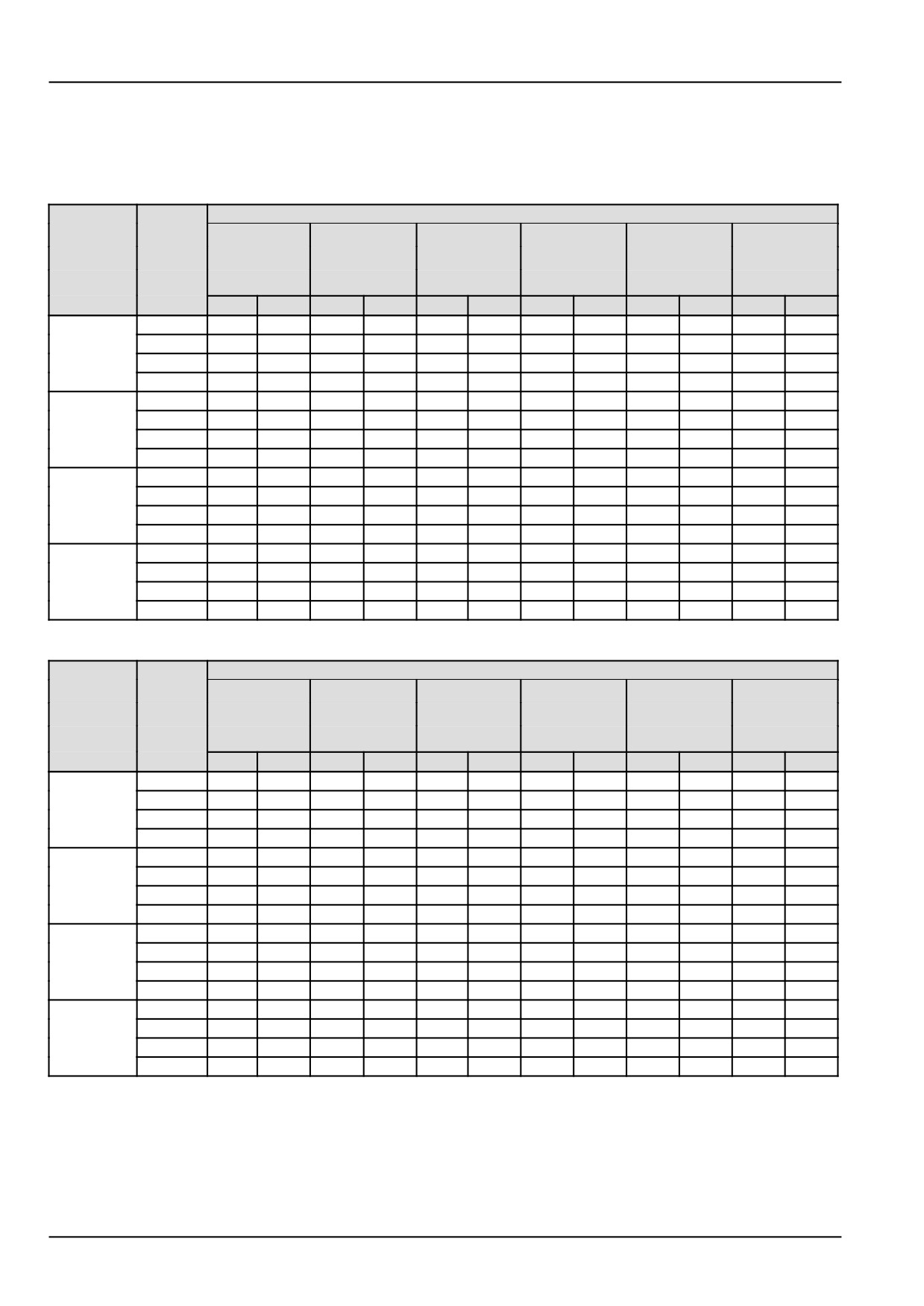
SPEED AT MAXIMUM POWER
Transmission 40 km/h (24.9 mph) version
16 FWD + 16 REV
FORWARD SPEED
REAR TIRES
13.6 R 28
14.9 R 28
340/85 R 28
RANGE
GEAR
380/70 R 20
380/70 R 24
420/70 R 24
380/85 R 28
420/70 R 30
380/70 R 28
420/70 R 28
19.5L - 24
km/h
mph
km/h
mph
km/h
mph
km/h
mph
km/h
mph
km/h
mph
1
0,83
0.52
0,70
0.44
0,73
0.46
0,76
0.47
0,79
0.49
0,82
0.51
2
1,24
0.77
1,41
0.87
1,09
0.68
1,14
0.71
1,18
0.74
1,23
0.76
A
3
1,82
1.13
1,54
0.96
1,61
1.00
1,67
1.04
1,74
1.08
1,81
1.12
4
2,7
1.68
2,28
1.42
2,38
1.48
2,48
1.54
2,58
1.60
2,68
1.66
1
3,5
2.17
2,95
1.83
3,08
1.91
3,21
1.99
3,34
2.07
3,46
2.15
2
5,21
3.24
4,4
2.73
4,59
2.85
4,78
2.97
4,97
3.09
5,16
3.21
BL
3
7,66
4.76
6,47
4.02
6,75
4.19
7,03
4.37
7,31
4.54
7,59
4.72
4
11,35
7.05
9,58
5.95
10
6.21
10,41
6.47
10,83
6.73
11,24
6.99
1
4,28
2.66
3,61
2.24
3,77
2.34
3,93
2.44
4,08
2.54
4,24
2.63
2
6,38
3.97
5,38
3.35
5,62
3.49
5,85
3.64
6,09
3.78
6,32
3.93
BH
3
9,38
5.83
7,92
4.92
8,26
5.13
8,60
5.35
8,95
5.56
9,29
5.77
4
13,9
8.64
11,73
7.29
12,24
7.60
12,75
7.92
13,26
8.24
13,77
8.55
1
12,36
7.68
10,43
6.48
10,88
6.76
11,34
7.04
11,79
7.33
12,24
7.61
2
18,42
11.45
15,55
9.66
16,22
10.08
16,9
10.50
17,57
10.92
18,25
11.34
C
3
27,08
16.83
22,85
14.20
23,85
14.82
24,84
15.43
25,83
16.05
26,83
16.67
4
40,12
24.93
33,85
21.04
35,33
21.95
36,80
22.87
38,27
23.78
39,74
24.70
REVERSE SPEED
REAR TIRES
13.6 R 28
14.9 R 28
340/85 R 28
RANGE
GEAR
380/70 R 20
380/70 R 24
420/70 R 24
380/85 R 28
420/70 R 30
380/70 R 28
420/70 R 28
19.5L - 24
km/h
mph
km/h
mph
km/h
mph
km/h
mph
km/h
mph
km/h
mph
1
0,81
0.50
0,68
0.42
0,71
0.44
0,74
0.46
0,77
0.48
0,79
0.49
2
1,20
0.75
1,01
0.63
1,06
0.66
1,10
0.68
1,15
0.71
1,19
0.74
A
3
1,77
1.10
1,49
0.93
1,56
0.97
1,62
1.01
1,69
1.05
1,75
1.09
4
2,62
1.63
2,21
1.37
2,3
1.43
2,40
1.49
2,50
1.55
2,59
1.61
1
3,39
2.11
2,86
1.78
2,98
1.85
3,11
1.93
3,23
2.01
3,36
2.08
2
5,05
3.14
4,26
2.65
4,45
2.76
4,63
2.88
4,82
2.99
5,00
3.11
BL
3
7,42
4.61
6,26
3.89
6,54
4.06
6,81
4.23
7,08
4.40
7,35
4.57
4
11,00
6.83
9,28
5.77
9,68
6.02
10,09
6.27
10,49
6.52
10,89
6.77
1
4,15
2.58
3,5
2.17
3,65
2.27
3,80
2.36
3,96
2.46
4,11
2.55
2
6,18
3.84
5,22
3.24
5,44
3.38
5,67
3.52
5,90
3.66
6,12
3.80
BH
3
9,09
5.65
7,67
4.76
8,00
4.97
8,33
5.18
8,67
5.39
9,00
5.59
4
13,46
8.37
11,36
7.06
11,85
7.37
12,35
7.67
12,84
7.98
13,34
8.29
1
11,97
7.44
10,1
6.28
10,54
6.55
10,98
6.82
11,42
7.10
11,86
7.37
2
17,85
11.09
15,06
9.36
15,71
9.76
16,37
10.17
17,02
10.58
17,68
10.99
C
3
26,24
16.30
22,14
13.76
23,1
14.35
24,06
14.95
25,03
15.55
25,99
16.15
4
38,87
24.15
32,8
20.38
34,22
21.27
35,65
22.15
37,07
23.04
38,50
23.92
3-40
3 - CONTROLS/INSTRUMENTS
Transmission with gear reducer and electrohydraulic reversing
mechanism
30 km/h (18.6 mph) - 40 km/h (24.9 mph) - 16FWD +
16REV
WARNING
Unexpected machine movement!
With the engine running and only the gear
lever in neutral, the machine can engage and
move suddenly if someone accidentally op-
erates this lever. Place all levers in neutral,
disengage the power take-off, lower any im-
plements, and set the parking brake before
exiting the machine. Use wheel chocks when
parking on slopes.
Failure to comply could result in death or se-
rious injury.
W0057B
MOIL13TR00799AA
1
The gear lever (1) selects four gear ratios (1 - 2 - 3 - 4).
The range lever (2) provides four ranges:
A
slow
BL
medium slow
BH
medium fast
C
fast
Separate use of the gear lever (1), the range lever (2) fig.
1 and the shuttle lever (1) fig. 3 allows 16 forward gears
and 16 reverse gears to be selected.
The tractor must always be stopped to change from one
range to another. To change from one speed to another
within the same range, disengage the clutch and move
the gear lever (the tractor does not need to be stationary
as the gears are synchro−engaged).
MOIL13TR00518AA
2
Power shuttle lever
The lever (1), located to the left of the driver’s seat, is
used to select forward or reverse when a gear ratio is
engaged. To select the drive direction, lift the lever and
move it forward for forward drive, or backward for reverse
drive. Drive direction can be selected without pressing
down the clutch pedal. To change the drive direction keep
the lever raised and move it either forwards or backwards.
Drive direction can be changed without pressing down the
clutch pedal.
NOTE: In order to start the engine, move the shuttle con-
trol lever (1) to the central neutral position. In addition,
MOIL13TR00505AA
3
it is recommended to press the transmission clutch pedal
fully down.
3-41
3 - CONTROLS/INSTRUMENTS
SPEED AT MAXIMUM POWER
Transmission 30 km/h (18.6 mph) version
16 FWD + 16 REV
FORWARD SPEED
REAR TIRES
13.6 R 28
14.9 R 28
340/85 R 28
RANGE
GEAR
380/70 R 20
380/70 R 24
420/70 R 24
380/85 R 28
420/70 R 30
380/70 R 28
420/70 R 28
19.5L - 24
km/h
mph
km/h
mph
km/h
mph
km/h
mph
km/h
mph
km/h
mph
1
0,64
0.40
0,54
0.34
0,57
0.35
0,59
0.37
0,62
0.38
0,64
0.40
2
0,96
0.59
0,81
0.50
0,85
0.53
0,88
0.55
0,92
0.57
0,95
0.59
A
3
1,41
0.87
1,19
0.74
1,24
0.77
1,30
0.81
1,35
0.84
1,4
0.87
4
2,80
1.74
1,77
1.10
1,84
1.15
1,92
1.19
2,0
1.24
2,07
1.29
1
2,69
1.67
2,29
1.42
2,39
1.48
2,49
1.54
2,59
1.61
2,69
1.67
2
4,02
2.50
3,41
2.12
3,56
2.21
3,71
2.30
3,85
2.39
4,0
2.49
BL
3
5,90
3.67
5,01
3.11
5,23
3.25
5,45
3.38
5,67
3.52
5,88
3.66
4
8,75
5.43
7,42
4.61
7,75
4.81
8,07
5.01
8,39
5.22
8,72
5.42
1
3,30
2.05
2,8
1.74
2,92
1.82
3,04
1.89
3,62
2.25
3,29
2.04
2
4,92
3.05
4,17
2.59
4,36
2.71
4,54
2.82
4,72
2.93
4,9
3.04
BH
3
7,23
4.49
6,14
3.81
6,4
3.98
6,67
4.14
6,94
4.31
7,2
4.48
4
10,71
6.65
9,09
5.65
9,48
5.89
9,88
6.14
10,27
6.38
10,67
6.63
1
9,52
5.92
8,08
5.02
8,43
5.24
8,79
5.46
9,14
5.68
9,49
5.90
2
14,19
8.82
12,05
7.49
12,57
7.81
13,10
8.14
13,62
8.46
14,15
8.79
C
3
20,86
12.96
17,71
11.01
18,48
11.48
19,25
11.96
20,02
12.44
20,79
12.92
4
30,91
19.21
26,24
16.31
27,38
17.01
28,52
17.72
29,66
18.43
30,80
19.14
REVERSE SPEED
REAR TIRES
13.6 R 28
14.9 R 28
340/85 R 28
RANGE
GEAR
380/70 R 20
380/70 R 24
420/70 R 24
380/85 R 28
420/70 R 30
380/70 R 28
420/70 R 28
19.5L - 24
km/h
mph
km/h
mph
km/h
mph
km/h
mph
km/h
mph
km/h
mph
1
0,62
0.39
0,53
0.33
0,55
0.34
0,57
0.36
0,60
0.37
0,62
0.38
2
0,93
0.58
0,79
0.49
0,82
0.51
0,85
0.53
0,89
0.55
0,92
0.57
A
3
1,36
0.85
1,16
0.72
1,21
0.75
1,26
0.78
1,31
0.81
1,36
0.84
4
2,02
1.25
1,71
1.06
1,79
1.11
1,86
1.16
1,93
1.20
2,01
1.25
1
2,61
1.62
2,22
1.38
2,31
1.44
2,41
1.50
2,5
1.56
2,6
1.62
2
3,89
2.42
3,30
2.05
3,45
2.14
3,59
2.23
3,73
2.32
3,88
2.41
BL
3
5,72
3.55
4,86
3.02
5,01
3.11
5,28
3.28
5,49
3.41
5,7
3.54
4
8,47
5.26
7,19
4.47
7,51
4.66
7,82
4.86
8,13
5.05
8,44
5.25
1
3,2
1.99
2,71
1.69
2,83
1.76
2,95
1.83
3,07
1.91
3,18
1.98
2
4,76
2.96
4,04
2.51
4,22
2.62
4,4
2.73
4,57
2.84
4,75
2.95
BH
3
7,00
4.35
5,94
3.69
6,2
3.85
6,46
4.01
6,72
4.17
6,98
4.34
4
10,37
6.44
8,81
5.47
9,19
5.71
9,57
5.95
9,95
6.18
10,34
6.42
1
9,22
5.73
7,83
4.87
8,17
5.08
8,51
5.29
8,85
5.50
9,19
5.71
2
13,75
8.54
11,67
7.25
12,18
7.57
12,69
7.88
13,2
8.20
13,7
8.52
C
3
20,21
12.56
17,16
10.66
17,91
11.13
18,65
11.59
19,4
12.05
20,14
12.52
4
29,94
18.61
25,42
15.80
26,53
16.48
27,63
17.17
28,74
17.86
29,84
18.54
3-42
3 - CONTROLS/INSTRUMENTS
SPEED AT MAXIMUM POWER
Transmission 40 km/h (24.9 mph) version
16 FWD + 16 REV
FORWARD SPEED
REAR TIRES
13.6 R 28
14.9 R 28
340/85 R 28
RANGE
GEAR
380/70 R 20
380/70 R 24
420/70 R 24
380/85 R 28
420/70 R 30
380/70 R 28
420/70 R 28
19.5L - 24
km/h
mph
km/h
mph
km/h
mph
km/h
mph
km/h
mph
km/h
mph
1
0,83
0.52
0,70
0.44
0,73
0.46
0,76
0.47
0,79
0.49
0,82
0.51
2
1,24
0.77
1,41
0.87
1,09
0.68
1,14
0.71
1,18
0.74
1,23
0.76
A
3
1,82
1.13
1,54
0.96
1,61
1.00
1,67
1.04
1,74
1.08
1,81
1.12
4
2,7
1.68
2,28
1.42
2,38
1.48
2,48
1.54
2,58
1.60
2,68
1.66
1
3,5
2.17
2,95
1.83
3,08
1.91
3,21
1.99
3,34
2.07
3,46
2.15
2
5,21
3.24
4,4
2.73
4,59
2.85
4,78
2.97
4,97
3.09
5,16
3.21
BL
3
7,66
4.76
6,47
4.02
6,75
4.19
7,03
4.37
7,31
4.54
7,59
4.72
4
11,35
7.05
9,58
5.95
10
6.21
10,41
6.47
10,83
6.73
11,24
6.99
1
4,28
2.66
3,61
2.24
3,77
2.34
3,93
2.44
4,08
2.54
4,24
2.63
2
6,38
3.97
5,38
3.35
5,62
3.49
5,85
3.64
6,09
3.78
6,32
3.93
BH
3
9,38
5.83
7,92
4.92
8,26
5.13
8,60
5.35
8,95
5.56
9,29
5.77
4
13,9
8.64
11,73
7.29
12,24
7.60
12,75
7.92
13,26
8.24
13,77
8.55
1
12,36
7.68
10,43
6.48
10,88
6.76
11,34
7.04
11,79
7.33
12,24
7.61
2
18,42
11.45
15,55
9.66
16,22
10.08
16,9
10.50
17,57
10.92
18,25
11.34
C
3
27,08
16.83
22,85
14.20
23,85
14.82
24,84
15.43
25,83
16.05
26,83
16.67
4
40,12
24.93
33,85
21.04
35,33
21.95
36,80
22.87
38,27
23.78
39,74
24.70
REVERSE SPEED
REAR TIRES
13.6 R 28
14.9 R 28
340/85 R 28
RANGE
GEAR
380/70 R 20
380/70 R 24
420/70 R 24
380/85 R 28
420/70 R 30
380/70 R 28
420/70 R 28
19.5L - 24
km/h
mph
km/h
mph
km/h
mph
km/h
mph
km/h
mph
km/h
mph
1
0,81
0.50
0,68
0.42
0,71
0.44
0,74
0.46
0,77
0.48
0,79
0.49
2
1,20
0.75
1,01
0.63
1,06
0.66
1,10
0.68
1,15
0.71
1,19
0.74
A
3
1,77
1.10
1,49
0.93
1,56
0.97
1,62
1.01
1,69
1.05
1,75
1.09
4
2,62
1.63
2,21
1.37
2,3
1.43
2,40
1.49
2,50
1.55
2,59
1.61
1
3,39
2.11
2,86
1.78
2,98
1.85
3,11
1.93
3,23
2.01
3,36
2.08
2
5,05
3.14
4,26
2.65
4,45
2.76
4,63
2.88
4,82
2.99
5,00
3.11
BL
3
7,42
4.61
6,26
3.89
6,54
4.06
6,81
4.23
7,08
4.40
7,35
4.57
4
11,00
6.83
9,28
5.77
9,68
6.02
10,09
6.27
10,49
6.52
10,89
6.77
1
4,15
2.58
3,5
2.17
3,65
2.27
3,80
2.36
3,96
2.46
4,11
2.55
2
6,18
3.84
5,22
3.24
5,44
3.38
5,67
3.52
5,90
3.66
6,12
3.80
BH
3
9,09
5.65
7,67
4.76
8,00
4.97
8,33
5.18
8,67
5.39
9,00
5.59
4
13,46
8.37
11,36
7.06
11,85
7.37
12,35
7.67
12,84
7.98
13,34
8.29
1
11,97
7.44
10,1
6.28
10,54
6.55
10,98
6.82
11,42
7.10
11,86
7.37
2
17,85
11.09
15,06
9.36
15,71
9.76
16,37
10.17
17,02
10.58
17,68
10.99
C
3
26,24
16.30
22,14
13.76
23,1
14.35
24,06
14.95
25,03
15.55
25,99
16.15
4
38,87
24.15
32,8
20.38
34,22
21.27
35,65
22.15
37,07
23.04
38,50
23.92
3-43