New Holland Tractor T4.75F, T4.85F, T4.95F, T4.105F. OPERATOR’S MANUAL (2013) - page 6
7 - MAINTENANCE
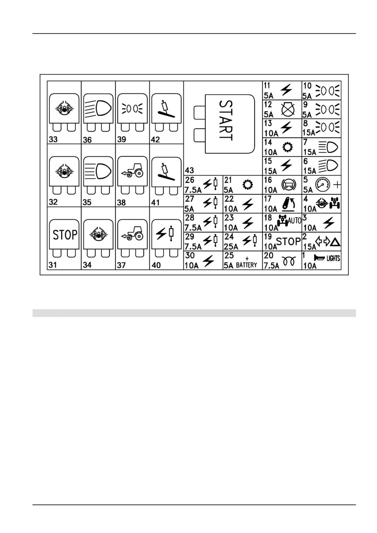
Fuses and relays location
Model with cab
MOIL13TR00725FA
1
NOTICE: Depending on your version some components described below might not be present.
Fuses
Ref.
Fuse Protected circuits
1
10 A Horn, driving beam flashing
2
15 A Turn and hazard lights.
3
10 A
8 A socket 8 A
4
10 A
Differential lock circuit, four-wheel drive circuit.
5
5 A
+ instrument cluster, electronic hydraulic lift switches and lamps
6
15 A Dipped beam headlight circuit.
7
15 A Full beam headlight circuit.
8
15 A Circuit of position lights or work lights for 7-pole socket.
9
5 A Front left-hand and rear right-hand position lights, instrument cluster light.
10
5 A Front right-hand and rear left-hand position lights, position lights indicator light.
11
5 A Engine starting safeties circuit.
12
5 A Engine shutdown electromagnet.
13
10 A Stabilizer lock circuit.
14
10 A Power Shuttle circuit
15
15 A Cab services relay, seat
16
10 A Trailer brake and hydraulic adjustment circuit.
17
10 A Electronic lift circuit.
18
10 A Permanent 4WD circuit
19
10 A Brake lights circuit.
20
7.5 A Grid heater controller circuit.
21
5 A Power Shuttle lever
22
10 A Circuit for second and third distributor, mid mount relay
7-51
7 - MAINTENANCE
Ref.
Fuse Protected circuits
23
10 A Circuit for right-hand tie rod control.
24
25 A Ventral control valves
25
5 A Battery cut-out circuit
26
7.5 A Ventral control valves
27
5 A Ventral control valves
28
7.5 A Ventral control valves
29
7.5 A Ventral control valves
30
10 A Power supply for keypad + key
Relay
Ref. Protected circuits
31
Brake lights (STOP)
32
Differential lock circuit
33
Differential lock circuit
34
Differential lock circuit
35
Full beam headlight circuit
36
Dipped beam headlight circuit
37
4WD circuit
38
Steering switch
39
Position lights circuit
40
Ventral control valves
41
Third hydraulic distributor
42
Second hydraulic distributor
43
Engine starting circuit maxi-relay
NOTE: If electrical system relays need to be changed, check that correct spare parts are used and that they are fitted
in the correct positions. The use of structurally or functionally different relays - even if interchangeable - may seriously
compromise tractor control with dangerous results.
7-52
7 - MAINTENANCE
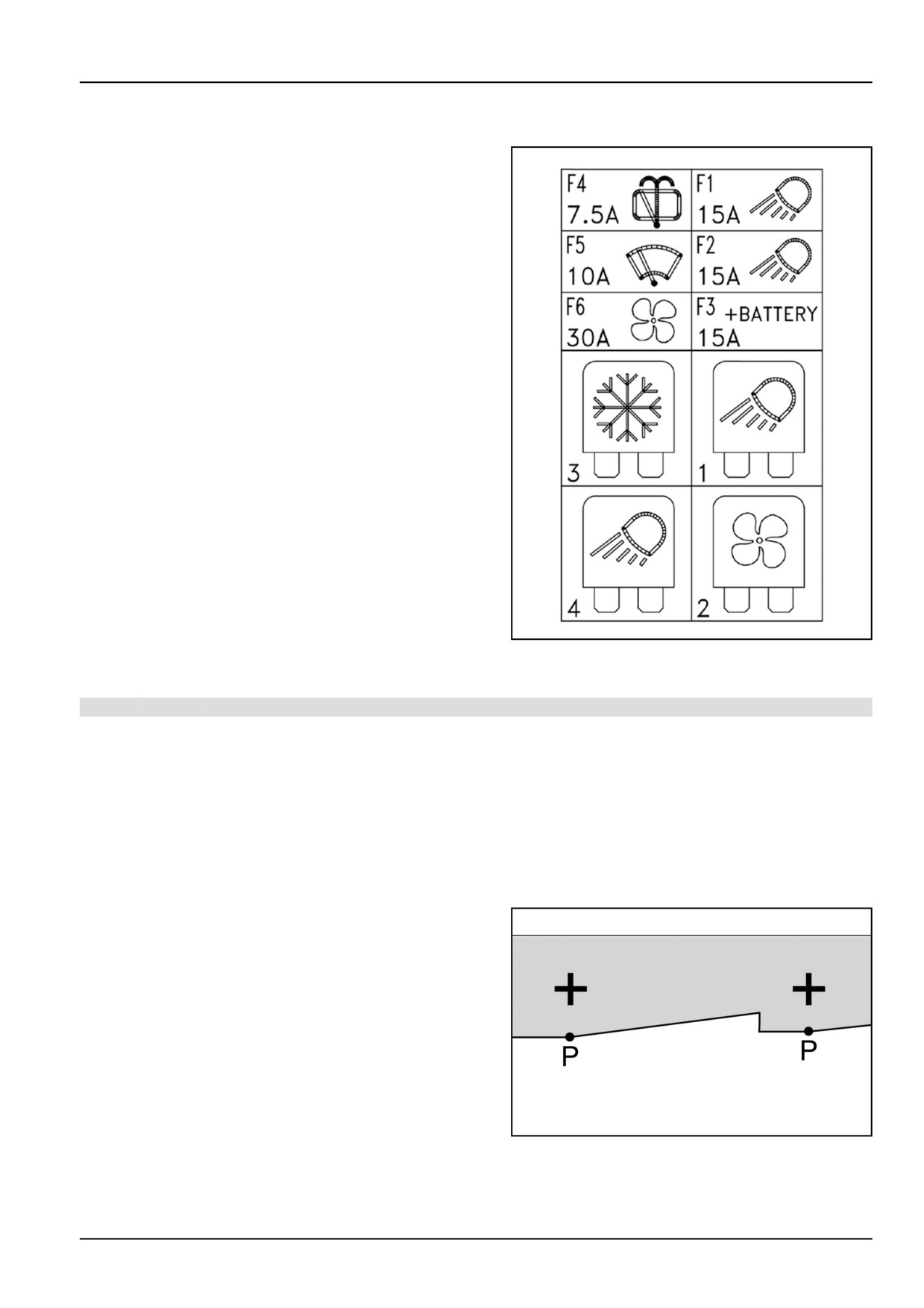
Fuses and relays location Fuses and relays on cab right hand upright
Cab relays
1. Front lights circuit.
2. Conditioner fan circuit.
3. Compressor circuit.
4. Rear lights circuit.
DCSPVNEGB069S7B
1
Fuses
Pos. Fuse Protected circuits
F1
15 A Front work lights.
F2
15 A Rear work lights.
F3
15 A Rotating beacon, cigar lighter and interior light.
F4
5 A Wiper -rear window.
F5
10 A Front windscreen wiper.
F6
30 A Fan and air conditioning circuit.
Headlight - Adjust
Adjust the front lights as follows:
• Park the unloaded tractor on flat ground, with the
tyres inflated to the specified pressure, facing a
shaded white wall;
• Mark two crosses on the wall, corresponding to the
centre of the headlights, as shown in figure.
• reverse the tractor by approximately 5 m (16.4 ft)
metres and turn the beam full on;
• Points P − P should be 5 cm (2.0 in) below the
crosses.
• To adjust the beams, use the screws (1) figure 2
DCAPLNEGB098S4A
1
inside the bonnet.
7-53
7 - MAINTENANCE
MOIL13TR00695AA
2
Headlight - Replace
NOTE: When handling halogen bulbs, only touch the metal parts, never the bulb. If the bulb comes into contact with
your fingers, the intensity of the light emitted will be reduced, adversely affecting its service life. In the event of contact,
clean the bulb with a cloth soaked in alcohol and leave to dry.
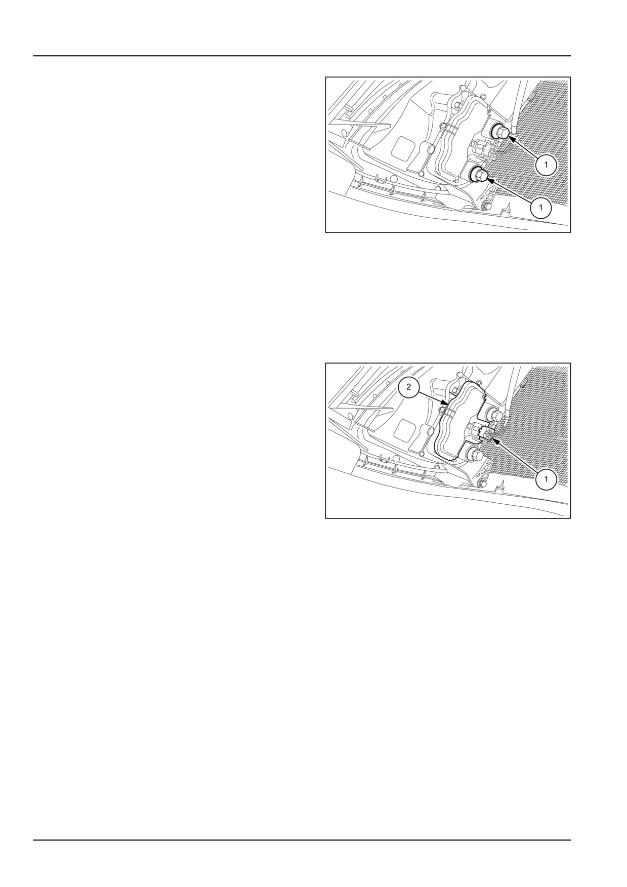
Full/dipped beam headlight bulbs:
1. Replace blown bulbs as follows:
• Raise the bonnet;
• Remove the fixing plugs (1);
• Take off the guard (2);
• Extract the light bulb and replace it with a new one
of the same power.
MOIL13TR00696AA
1
7-54
7 - MAINTENANCE
STORAGE
Tractor storage
NOTE: Take the following precautions if your tractor is going to remain unused for a prolonged period.
Protect the engine as follows:
• For storage periods of approx. one month: no steps are necessary if the engine oil has not yet exceeded 100
hours of work. Otherwise, proceed as described in the paragraph below.
• For storage periods of over one month, drain the oil from the engine while hot, fill up the reservoir with oil (see
"Topping-up" table on "Maintenance chapter") and run the engine for a few minutes at medium rpm.
• Remove the external air filter cartridge and clean according to the instructions provided on "Maintenance chapter".
• Do not drain off the engine cooling system. During winter periods, make sure that the proportions of the water/fluid,
supplied with the tractor, are as specified (see "Topping-up" table on "Maintenance chapter"). To this end, follow
the instructions on "Maintenance chapter"..
• Clean the tractor and the bodywork.
Protect the paintwork with silicone wax and use protective lubricants on non-painted metal parts; always keep the
tractor in a covered, dry and well-ventilated place.
• Check that all controls are left in neutral (including electrical switches and the parking brake control).
• Do not leave the ignition key in the switch.
• Make sure that the operating cylinder rods (hydrostatic steering, lift, etc.) are closed up to protect them.
• Fill the fuel tank with diesel fuel.
• Remove the battery, clean the cover and smear the terminals and lead ends with petroleum jelly; next, place the
battery in a ventilated spot not exposed to temperatures less than 10 °C (50.0 °F) and away from direct sunlight.
• Check the battery charge condition using a voltmeter, as described on "Maintenance chapter".
• Fit stands or other suitable supports under the axles to raise the wheels off the ground. While the tractor is in a
raised position, we recommend you let the air out of the tyres. Otherwise, raise the tractor and check the tyre
pressure from time to time.
• Cover the tractor with a non-plastic non-waterproof sheet.
NOTICE: When the engine is to be re-started at the end of the storage period, closely follow the instructions relating
to starting the engine.
7-55
7 - MAINTENANCE
CALIBRATIONS
Dual command calibration
WARNING
Unexpected machine movement!
The machine could move automatically during calibration. Park on a flat surface, engage the parking
brake, and be sure that the area around the machine is clear before starting the calibration process.
Failure to comply could result in death or serious injury.
W0300A
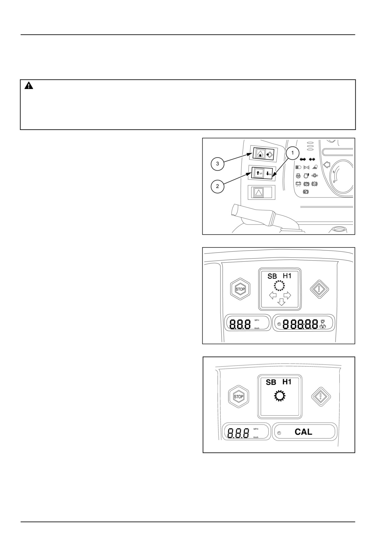
1.
Do the setting as described below.
During the setting procedure, if a four digit number
starting with 2 is displayed, it is a standard error code.
Before doing the calibration it is necessary to remedy
the trouble.
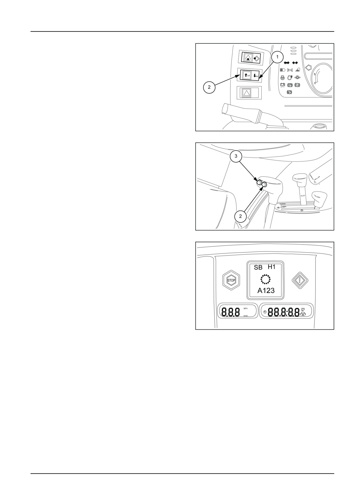
To enter this mode press the service symbol on the
switch (3) while starting up the engine. Scroll through
the HH menu using the arrows (1) and (2) on the switch
of fig. 1, to select code SB and menu H1, as in fig. 2.
(Shortcut − press and hold switch (3) fig.
1
(Home)
while starting the engine. Kick on release). “CAL” will
briefly be displayed on the display at bottom right of the
instrument cluster as in fig. 3, then the oil temperature
(degrees Celsius) will be displayed (XXC or XXXC).
MOIL13TR00707AA
1
2.
Select 3rd range and 1st gear.
Turn off the air−conditioner, where applicable.
Set engine to 1300 RPM +/− 100 and release the clutch
pedal. Engine speed must be stable, with no noticeable
hunting or surging. If necessary, change the throttle
setting slightly to achieve a stable engine rpm.
MOIL13TR00708AA
2
3. Check that the handbrake is on. Release the clutch
pedal.
Place the shuttle lever in forward (NOT IN NEUTRAL
or REVERSE).
THE SETTING IS ONLY POSSIBLE WITH THE OP-
ERATOR SITTING IN THE DRIVING SEAT.
DCSPVNEGB086S7A
3
7-56
7 - MAINTENANCE
4. Press and release the arrow (1) fig. 4 or the push−but-
ton (2) LO fig.
5. The display on the right will show
a cursor shortly followed by the letter corresponding to
the clutch involved in the setting with a three−digit num-
ber that increases
MOIL13TR00710AA
4
5. When the display shows the letter corresponding to the
clutch being calibrated, press and hold down the arrow
(2) fig. 4 or the push−button (2) LO fig. 5.
In this phase the calibration phase begins and the dis-
play shows a numerical value in mA that progressively
increases. When the numerical progression stops, the
value of the calibration current blinks.
MOIL13TR00711AA
5
6. Release the arrow (2) fig. 4 or the push button (2) LO
fig.
5. Press the arrow (1) fig.
4 or HI (3) fig.
5 to
display the next clutch to calibrate, for example: B
MOIL13TR00712AA
6
NOTICE: Transmission output rpm, clutch pedal position, shuttle lever position, and gear/range lever position are
constantly monitored. Calibration cannot proceed unless the tractor is stopped, shuttle lever in gear, gear and range
levers not in neutral, and the clutch pedal is up. If while in calibration an anomalous condition is detected it is shown on
the display with its error code via the alarm lamp, if the error is related to the calibration, then its ‘U’ code is displayed
on the LCD. See the list of related codes on the next page.
NOTE: If the letter related to the clutch does not appear and the cursor keeps on scrolling at the bottom of the display,
it means that the engine speed is not constant.
7-57

7 - MAINTENANCE
LIST OF ERROR CODES “U” ELECTROHYDRAULIC TRANSMISSIONS
U CODE
MEANING
17
Seat switch not activated.
18
Correct start−up procedure was not used.
19
Transmission oil temperature low (Below 10 °C (50.0 °F).
20
Handbrake is not set.
21
Engine RPM below 1150, increase throttle.
22
Engine RPM above 1350, reduce throttle.
23
Shuttle lever is in neutral, shift lever to forward.
26
Clutch pedal is not up, release clutch pedal.
31
Wheel speed sensed, check handbrake and start again.
A Clutch cal too low − RPM dropped too soon, clutch pressure is not being controlled properly or
32
something else caused RPM to drop.
A Clutch cal too high − RPM did not drop, no pressure to clutch or mechanical failure breaking the
33
torque path.
B Clutch cal too low − RPM dropped too soon, clutch pressure is not being controlled properly or
34
something else caused RPM to drop.
B Clutch cal too high − RPM did not drop, no pressure to clutch or mechanical failure breaking the
35
torque path.
49
No movement of the synchronizer sensed.
51
Engine speed error.
60
Range lever in Neutral.
61
Gear lever in Neutral.
64
Reverse and high synchronizer solenoid connectors swapped.
Synchronizer potentiometer signal is not within allowable limits for HI−LO position; bad potentiometer
91
signal or jammed synchronizer.
Synchronizer potentiometer signal is not within allowable limits for shuttle position; bad potentiometer
92
signal or jammed synchronizer.
111
Unable to calibrate Transmission.
NOTE: In cold or hot transmission oil conditions will still be possible to calibrate the clutches, however this will be
signalled to the operator by means of the warnings:
CL
COLD OIL WARNING, generated when the oil temperature is between 10 °C (50.0 °F) and 20 °C
(68.0 °F). At temperatures below 10 °C (50.0 °F) it is not possible to calibrate the clutches.
CH
HOT OIL WARNING, generated when the oil temperature is above 100 °C (212.0 °F).
7-58
8 - TROUBLESHOOTING
8 - TROUBLESHOOTING###_8_###
FAULT CODE RESOLUTION
Display fault codes
Indicator
Audible
Fault code
Symbol
Function
(Amber)
warning
on
14001
Rear PTO short to VCC
NO
YES
14002
Rear PTO short to GND
NO
YES
14011
Engine speed sensor short to VCC or open circuit
YES
YES
14012
Engine speed sensor short to GND
YES
YES
14015
5 V supply voltage too high
NO
YES
14016
5 V supply voltage too low
NO
YES
14021
Cranking line shorted to VCC
NO
YES
14022
Cranking line shorted to GND
NO
YES
14041
Engine coolant temp short to VCC or open circuit
YES
YES
14042
Engine coolant temp short to GND
YES
YES
14051
Fuel level sensor short to VCC or open circuit
NO
YES
14052
Fuel level sensor short to GND
NO
YES
14058
Seat switch closed over 25 hours
YES
YES
14091
Transmission out speed short to VCC
NO
YES
14092
Transmission out speed short to GND
NO
YES
14093
Seat switch short to VCC or open circuit
YES
YES
8-1
8 - TROUBLESHOOTING
Indicator
Audible
Fault code
Symbol
Function
(Amber)
warning
on
14094
Seat switch short to GND
YES
YES
14101
Fuel contaminated sensor Not connected
YES
YES
14103
Alternator lamp not working
NO
YES
14106
Front PTO present but not configured
NO
YES
14107
Front Hitch present but not configured
NO
YES
14108
Rear PTO sensor present but not configured
NO
YES
14201
Steering switch shorted to VCC or open circuit
YES
YES
14202
Steering switch shorted to GND
YES
YES
14203
Speed & Steer DT excude relay short to VCC or open circuit
YES
YES
14204
Speed & Steer DT excude relay short to GND
YES
YES
14900
MCM missing
NO
NO
14905
Keypad missing
NO
NO
14906
PSS missing
NO
NO
14911
Instrument panel without keypad
NO
YES
14912
Instrument panel with keypad
NO
YES
14061
Air brake pressure
YES
YES
8-2
8 - TROUBLESHOOTING
TROUBLESHOOTING ENGINE
WARNING
Avoid injury! Always do the following before lubricating, maintaining, or servicing the machine.
1. Disengage all drives.
2. Engage parking brake.
3. Lower all attachments to the ground, or raise and engage all safety locks.
4. Shut off engine.
5. Remove key from key switch.
6. Switch off battery key, if installed.
7. Wait for all machine movement to stop.
Failure to comply could result in death or serious injury.
W0047A
WARNING
Improper operation or service of this machine can result in an accident.
If you do not understand a maintenance procedure, or doubt your ability to perform a maintenance
procedure correctly, see your authorized dealer.
Failure to comply could result in death or serious injury.
W0157A
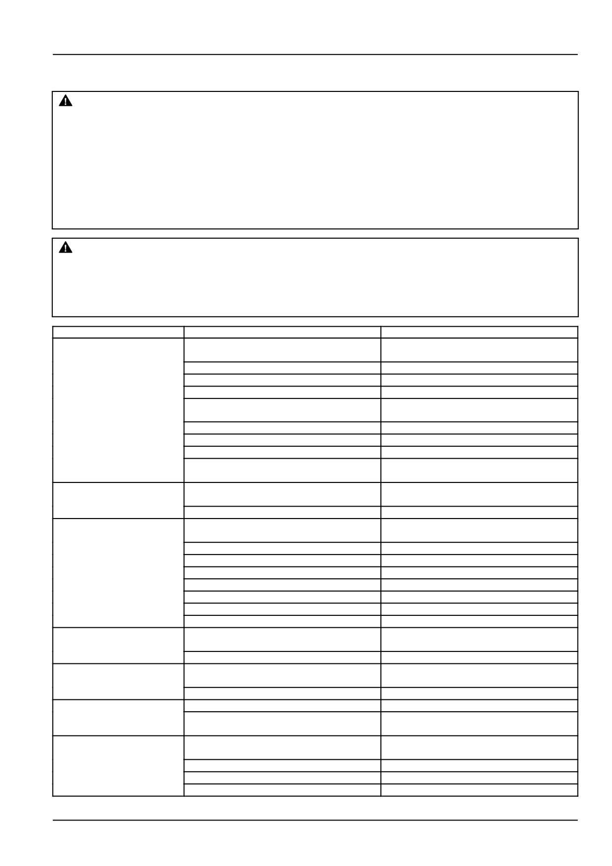
Problem
Possible Cause
Correction
The engine will not start
Incorrect starting procedure
See starting procedure
or starts with difficulty
Fuel level low or empty
Check the fuel level
Air in fuel system
Bleed fuel system
Engine oil viscosity not right
Use oil of right viscosity
Fuel not suitable for ambient temperature
Use correct type of fuel for temperature
conditions
Fuel system contaminated
Clean system
Fuel filter clogged
Replace filter element
Fuel injector fault
Contact your dealer
Battery isolator activated, or fuse and relay
Disconnect the battery isolator, check and
faulty
if necessary change the fuse or the relay
The engine does not run
Fuel system contaminated
Clean system
properly and/or cuts out
Fuel injector fault
Contact your dealer
Engine does not develop
Engine overload
Change to lower gear or reduce load
full power
Air filter clogged
Carry out maintenance on air filter
Incorrect fuel type
Use the right fuel
Low engine operating temperature
Check thermostat
Fuel injector fault
Have your dealer check the injectors
Implement incorrectly set
See equipment manual
Improper valve clearance
Check and adjust
Idling speed too low
Contact your dealer
Abnormal engine
Oil level low
Top up fluid level
knocking
Oil pressure low
Contact your dealer
Low engine operating
Thermostat malfunction
Replace thermostat
temperature
Fan viscous coupling malfunction
Contact your Dealer
Oil pressure low
Oil level low
Add oil as required
Oil grade or viscosity wrong
Drain and refill with oil of correct grade and
viscosity
Excessive oil
Oil level too high
Reduce oil level
consumption
Oil viscosity wrong
Use oil of correct viscosity
Oil leaking
Repair leaks
Breather pipe filter clogged
Replace breather pipe filter
8-3
8 - TROUBLESHOOTING
Problem
Possible Cause
Correction
Engine overheating
Radiator core clogged
Clean radiator
Engine overload
Change to lower gear or reduce load
Engine oil level low
Top up fluid level
Coolant level low
Top up fluid level in expansion tank. Check
system for leaks
Radiator cap defective
Replace cap
Fan belt slipping or worn
Check tensioning device. If necessary, re-
place the belt
Cooling system clogged
Flush cooling system
Thermostat malfunction
Check thermostat
Hoses leaking
Tighten hose connectors
Temperature indicator or gauge malfunc-
Contact your dealer
tion
Excessive fuel
Incorrect fuel type
Use right fuel type
consumption
Air filter dirty or clogged
Carry out maintenance on air filter
Engine overload
Change to lower gear or reduce load
Improper valve clearance
Check and adjust
Equipment wrongly adjusted
Refer to equipment manual for correct op-
eration
Engine temperature too low
Check thermostat
Excessive ballast
Adjust ballast to correct weight
Fuel injection nozzles clogged
Have your dealer service the injectors
8-4
8 - TROUBLESHOOTING
Electrical system - Troubleshooting ELECTRICAL SYSTEM
Problem
Possible Cause
Correction
The electrical system
Battery terminals loose or corroded
Clean and tighten terminals
does not work
Battery
Check that battery charge is at least 12.6 V.
Check electrolyte level and specific gravity
Batteries not charging
Terminals loose or corroded
Clean and tighten terminals
Battery
Check that battery charge is at least 12.6 V.
Check electrolyte level and specific gravity
Belt loose or worn
Check belt tensioning device. If necessary,
replace the belt
Low starter motor speed
Connections loose or corroded
Clean and tighten loose connections
and difficulty in starting
engine
Battery
Check that battery charge is at least 12.6 V.
Check electrolyte level and specific gravity
Engine oil viscosity wrong
Use oil of viscosity specified for tempera-
ture conditions
Starter motor does not
Gear lever engaged
Move gear lever to neutral
work
Connections loose or corroded
Clean and tighten terminals
Batteries totally flat
Charge or replace batteries
Battery charge light stays
Engine idling speed is low
Increase idling speed
on when engine is running
Alternator belt loose
Check belt tensioner
Battery fault
Check that battery charge is at least 12.6 V.
Check electrolyte level and specific gravity
Alternator fault
Have the alternator checked by your dealer
or an authorized workshop
The battery charge
Alternator fault
Have the alternator checked by your dealer
light flashes to indicate
excessive charge voltage
8-5
8 - TROUBLESHOOTING
Hydraulic systems - Troubleshooting HYDRAULIC SYSTEM
Problem
Possible Cause
Correction
The hydraulic system is
Oil level low
Top up system
not working properly
Hydraulic filter clogged
Replace hydraulic filter
Hydraulic system fault
Call your Dealer
Hydraulic fluid
Fluid level too high or low
Top up oil
overheating
Fluid filter element clogged
Replace filter
Incorrect flow regulation
Call your Dealer
Radiator block
Call your Dealer
Spool valve stuck on
Call your Dealer
Relief valve venting
Call your Dealer
Hoses not joined together
Damage male couplers
Replace couplers with standard ISO−1/2″
properly
connectors, available from your dealer
Dirt or soil in the coupling.
Clean the coupling
Automatic control valve
Automatic release pressure incorrectly set
Adjust automatic release pressure setting
release mechanism kick
out
Remote control valve
Hoses not connected correctly
Connect hoses correctly
does not work
Check the flow of oil in the half− couplers
Actuate control levers. If problems persist,
replace male half−couplers
System overload
Reduce load or use a suitable cylinder
Pump failure
Check if hitch goes up and down
8-6
8 - TROUBLESHOOTING
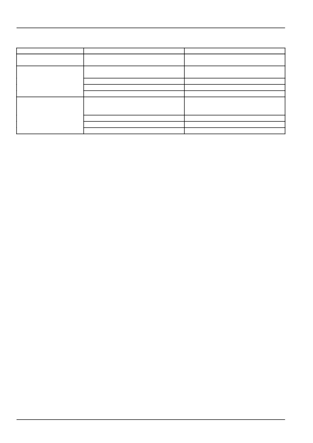
Rear three-point hitch - Troubleshooting HYDRAULIC LIFT AND
3−POINT LINKAGE
Problem
Possible Cause
Correction
The linkage does not
Linkage cylinder tubes not connected cor-
Connect linkage cylinder tubes correctly
move when the control
rectly
lever is actuated
Linkage overload
Reduce load
Implement does not raise
Arm lift upper limit control not set correctly
Adjust height limit control
to full height
The implement hitch
Lowering speed control incorrectly set
Have control valve checked
lowers slowly
The hydraulic lift operates
Combined draft/position control incorrectly
Adjust combined draft/position control
slowly in draft control
set
Lowering speed too slow
Have control valve checked
Implement not working properly
Adjust implement settings
The hydraulic lift operates
Combined draft/position control incorrectly
Have control valve checked
too fast in draft control
set
Electronically controlled
Call your Dealer
hydraulic lift fault code
signal
8-7
8 - TROUBLESHOOTING
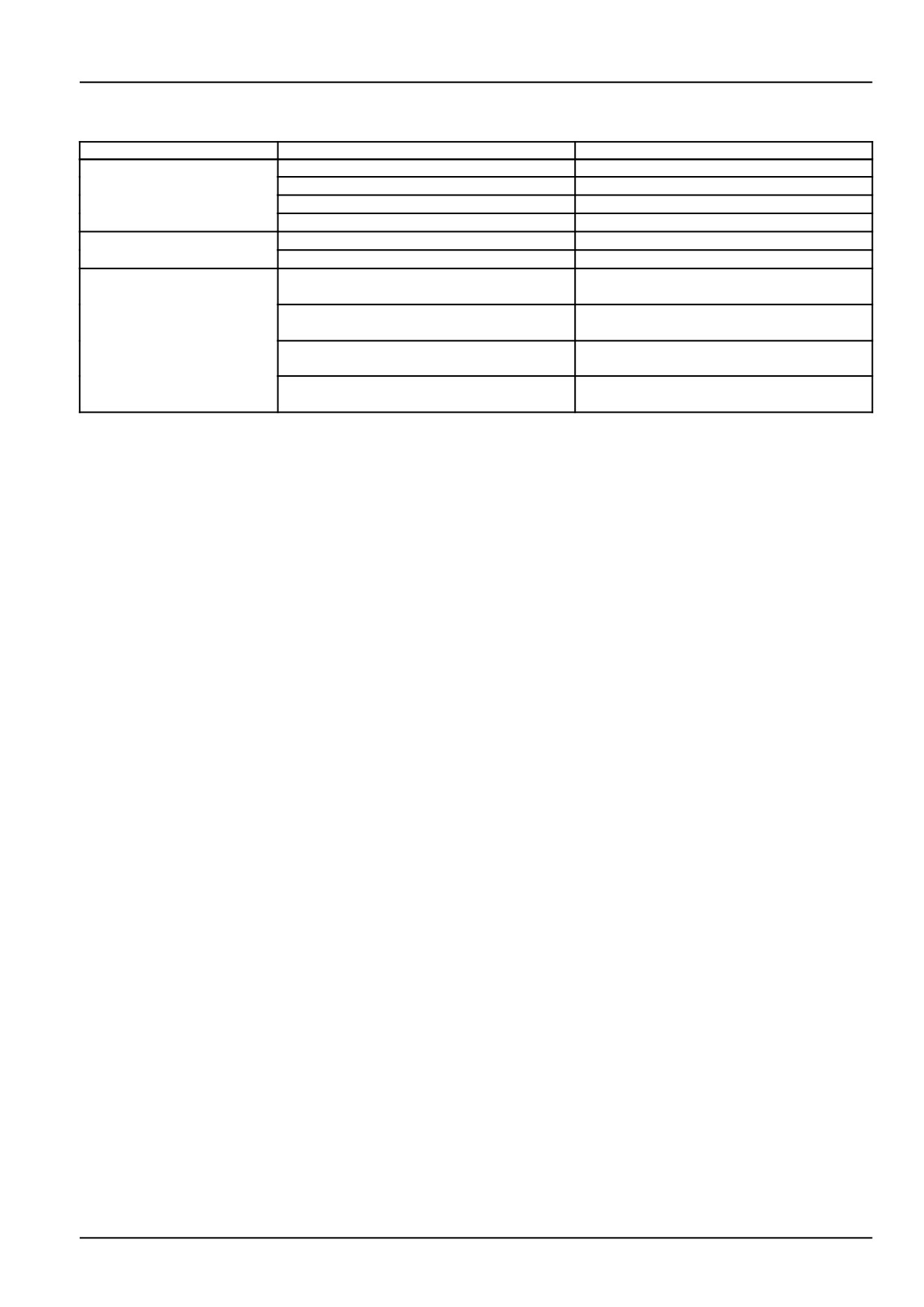
Hydraulic service brakes - Troubleshooting
Problem
Possible Cause
Correction
Pedals soft when engine
Air in the braking system
Call your Dealer
off
Pedal depresses fully with
Brake piston seals leaking
Call your Dealer
engine off
Brake discs worn
Call your Dealer
Brake release leaking
Call your Dealer
Brake valve(s) leaking
Call your Dealer
Excessive pedal travel or
Brake valve(s) leaking
Call your Dealer
resistance with engine
running
Air in the braking system
Call your Dealer
Brake piston seals leaking
Call your Dealer
Brake release leaking
Call your Dealer
8-8
8 - TROUBLESHOOTING
Cab climate control - Troubleshooting
Problem
Possible Cause
Correction
Dust in cab
Filter seal ineffective
Check condition of filter seal
Filter clogged
Clean or replace filter
Filter defective
Replace filter
Excessive air draughts
Block draughts
Poor recirculation air
Filter clogged or air circulation filter clogged
Clean or replace filter(s)
Heater or humidifier radiator core clogged
Call your Dealer
Air−conditioning not
Condenser clogged
Clean the radiator, oil exchanger and con-
cooling properly
denser
Refrigerant low
Check the glass port to see if there are bub-
bles visible. Call your Dealer
Compressor belt slips or is damaged
Check the automatic belt−tensioning de-
vice and the state of the belt
Heating on
Turn the temperature control fully
anti−clockwise for maximum cooling
8-9
8 - TROUBLESHOOTING
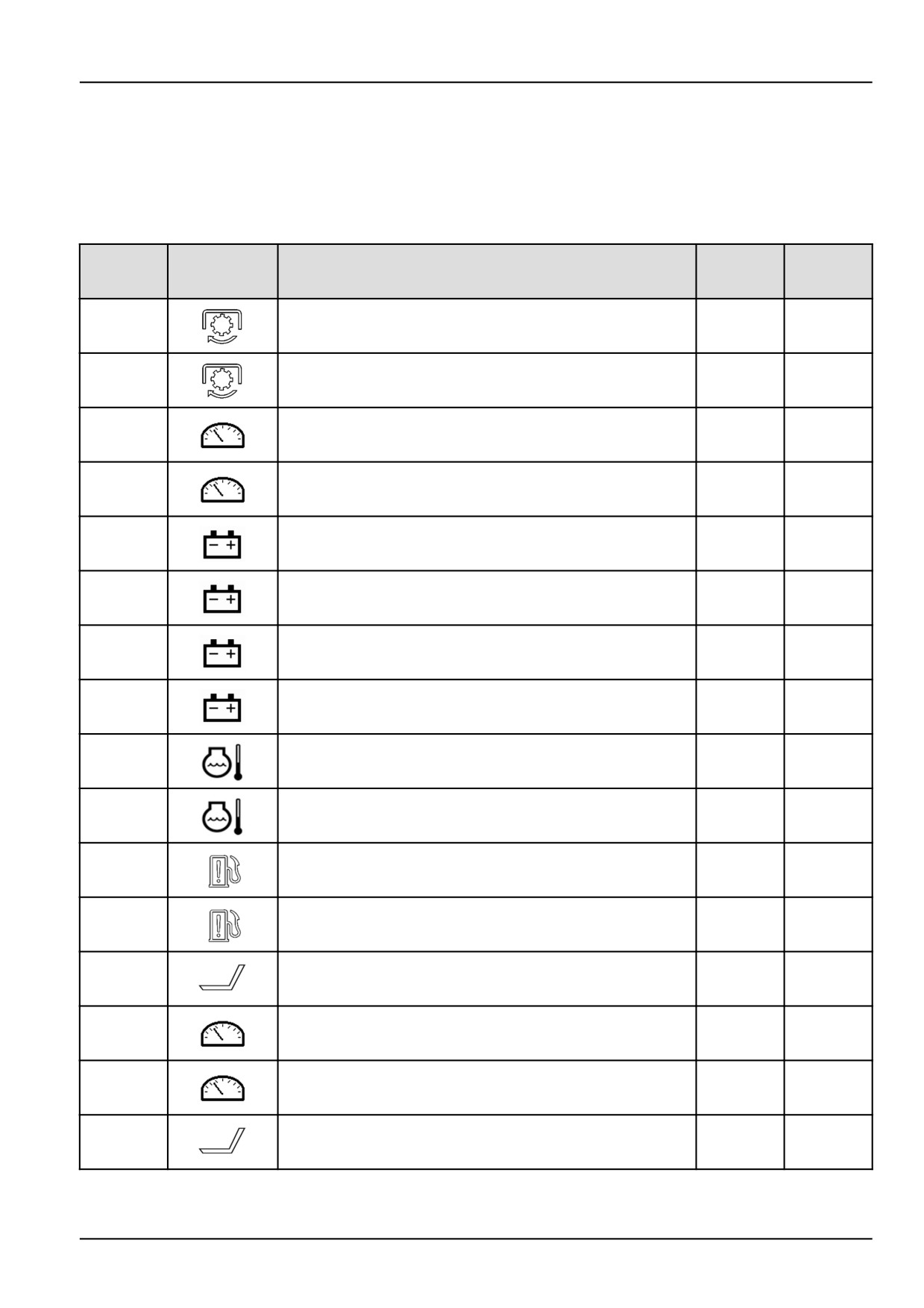
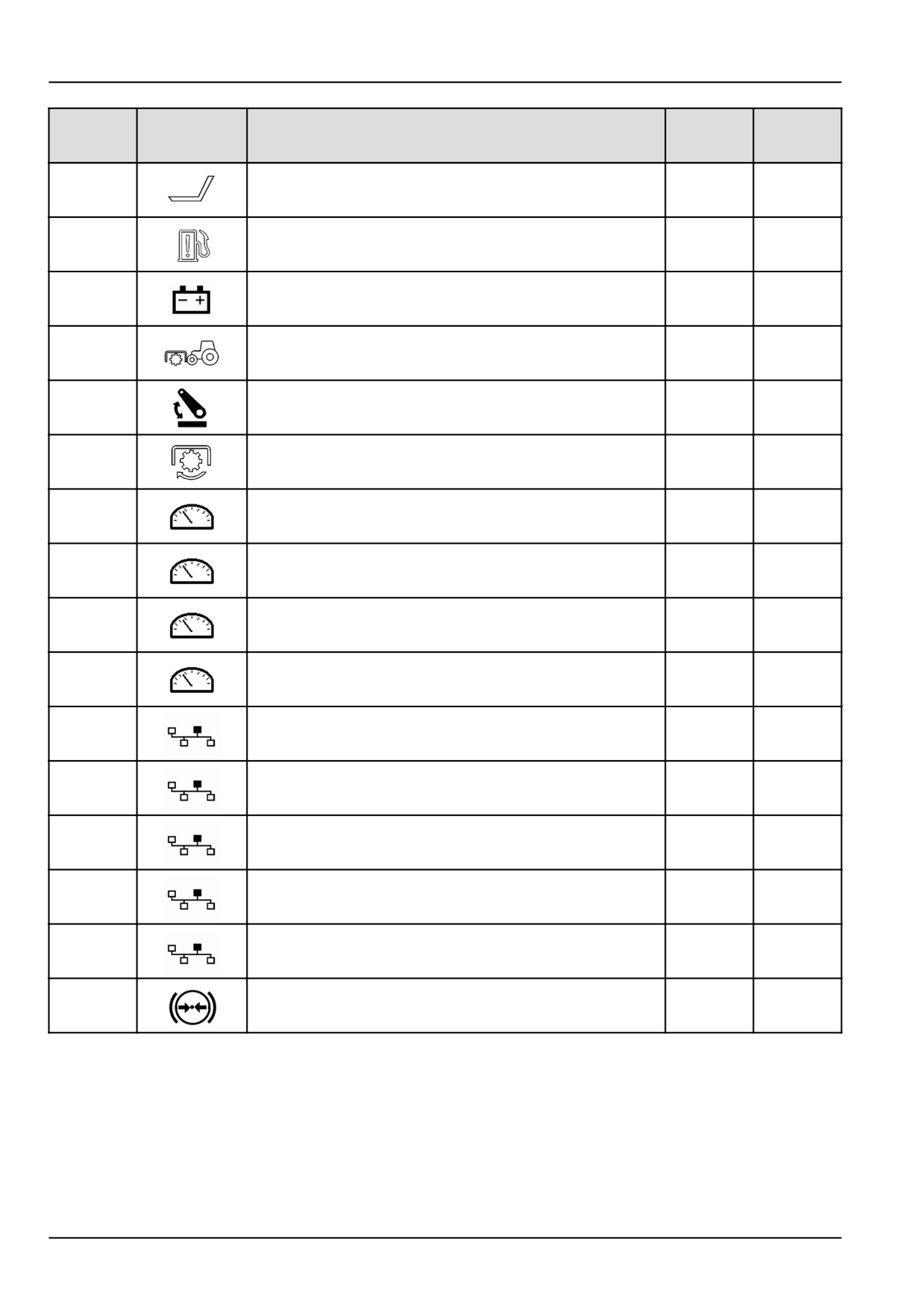
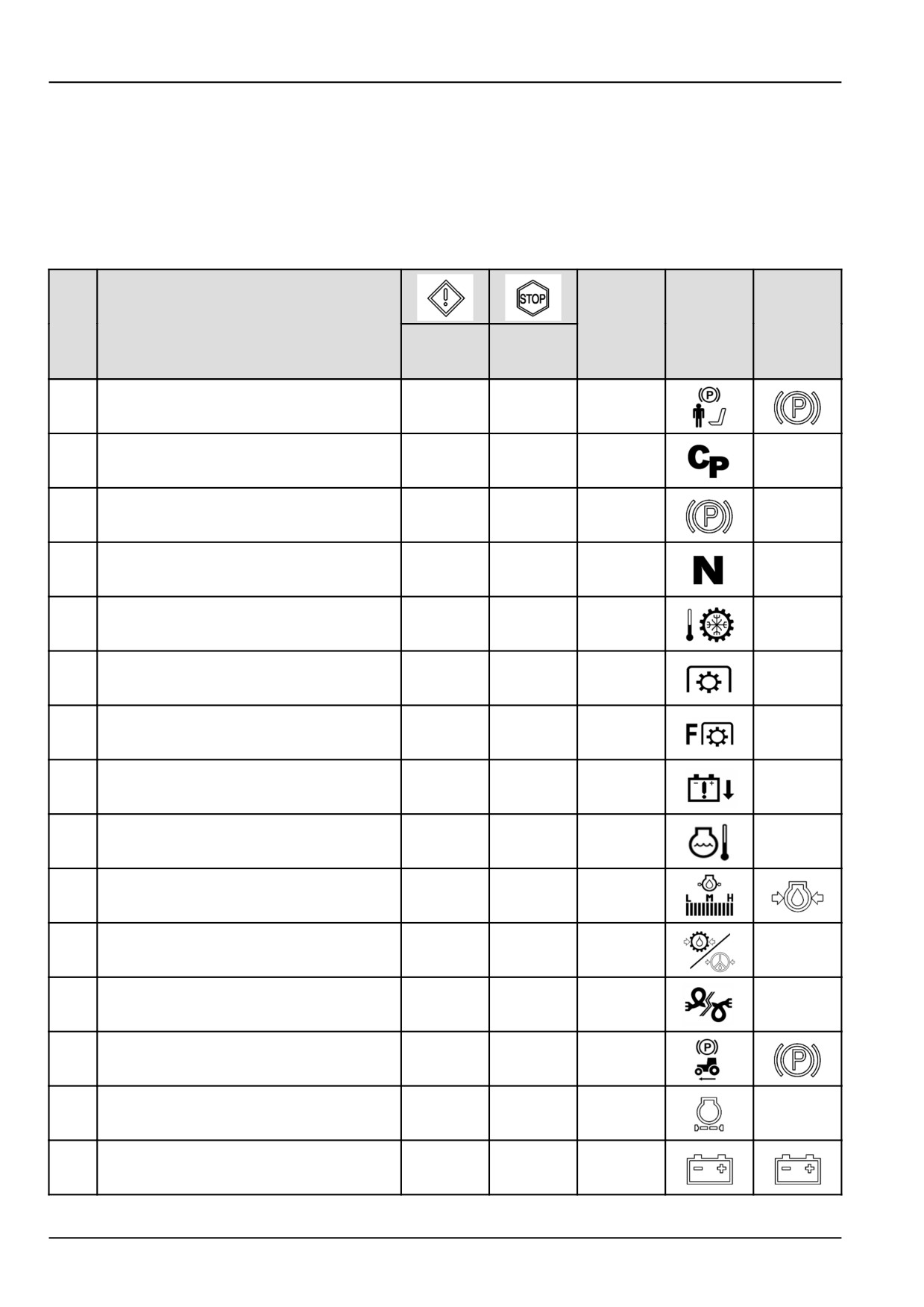
ALARM(S)
Alarms
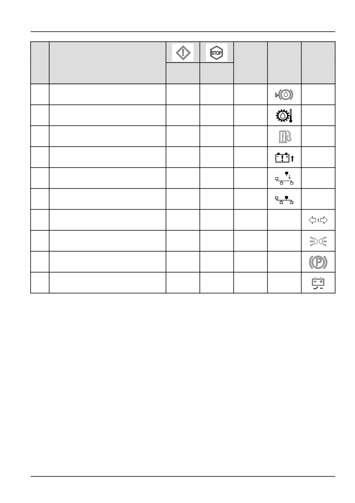
The following tables show:
• Start of activation of each single warning signalled on
the performance display.
• How each single operating fault is signalled to
the op-
erator.
• Possible action to remove the trouble.
Indicator
Symbol
lamp
Audible
Fault
Meaning
shown on
associated
Amber
Red
warning
the display
on the
indicator
indicator
instrumen
lamp
lamp
Operator not seated in driving seat, with
1
handbrake disengaged
YES
-
YES
Clutch
2
-
-
YES
-
Handbrake ON
3
-
-
YES
-
Power Shuttle lever
4
-
-
YES
-
Transmission oil
5
-
-
YES
-
Rear PTO
6
YES
-
YES
-
Front PTO
7
YES
-
YES
-
Battery voltage too low
8
YES
-
YES
-
Engine coolant temperature
9
-
YES
YES
-
Engine Oil Pressure Too Low
10
-
YES
YES
Power steering line oil pressure
11
-
YES
YES
-
Network Errors (CAN)
12
-
-
YES
-
Handbrake engaged while driving
13
-
-
YES
Engine air filter blocked
14
YES
-
-
-
Alternator charging failure
15
YES
-
-
8-10
8 - TROUBLESHOOTING
Indicator
Symbol
lamp
Audible
Fault
Meaning
shown on
associated
Amber
Red
warning
the display
on the
indicator
indicator
instrumen
lamp
lamp
Brake fluid level too low
16
-
-
-
Transmission oil temperature too high
17
YES
-
-
-
Fuel contaminated
18
YES
-
YES
-
Battery voltage too high
19
YES
-
-
-
Module configuration
20/1
-
YES
YES
-
Module configuration
20/2
-
-
-
-
Direction indicators
21
-
-
YES
-
Side lights (only on stopping the engine)
22
-
-
YES
-
Parking brake not engaged (only on
23
stopping the engine)
-
-
YES
-
Battery cut−off
24
-
-
YES
-
8-11
8 - TROUBLESHOOTING
Alarms, cause, solutions
Fault
POSSIBLE CAUSE
SOLUTION
The audible warning comes on with the related
Engage the handbrake. The signal must stop.
icon on the display when the operator leaves the
1
driving seat without engaging the handbrake or
with the seat safety switch broken.
The audible warning and indicator warn of an
Fully depress the clutch pedal and release it slowly.
2
incorrect or dangerous manoeuvre.
An audible warning is activated with the related
Disengage the handbrake. The signal must stop
3
icon on the display if the operator starts the tractor
when the brake is disengaged.
automatically with the handbrake engaged.
The audible warning and indicator warn of an
Move the Power Shuttle control lever into the
4
incorrect or dangerous manoeuvre.
neutral position.
The signal displayed shows that the transmission
Slow the engine down to idling and let it idle for 2/3
oil has exceeded its normal working temperature.
minutes. Switch off the engine and check that the
5
cooler is not clogged. Clean it if necessary.
IMPORTANT: If the problem is not resolved, do not
use the tractor and call your local dealer.
The audible warning comes on with the related
Move the rear PTO control lever into the neutral
icon on the display with the engine running when
position before leaving the driving seat.
6
the operator leaves the driving seat without
disengaging the PTO control lever or with the seat
safety switch broken.
The audible warning comes on with the related
Move the front PTO control lever into the neutral
icon on the display with the engine running when
position before leaving the driving seat.
7
the operator leaves the driving seat without
disengaging the PTO control lever or with the seat
safety switch broken.
The audible warning comes on with the related
Recharge/renew the battery.
8
icon on the display when the battery charge is low.
The audible warning comes on with the related
Stop the engine immediately and let it cool down.
icon on the display when the engine coolant
Make sure the radiator is clean and the fluid is at
9
temperature is too high.
the right level.
IMPORTANT: If the problem is not resolved, do not
use the tractor and call your local dealer.
The audible warning comes on with the related
Stop the tractor and call your dealer.
10
icon on the display and the instrument indicator
IMPORTANT: If the signal does not stop, do not
when the engine lubrication oil pressure is too low.
use the tractor and call your local dealer.
The audible warning comes on with the related
Stop the tractor and call your dealer.
icon on the display when the power steering oil
IMPORTANT: If the signal does not stop, do not
11
pressure is too low.
use the tractor and call your local dealer. Under
these conditions the steering could lock.
Potential problems in the electronic control unit
IMPORTANT: Call your local dealer immediately.
12
management network.
An audible warning is activated with the related
The signal must stop when the brake is
icon on the display with the tractor running
disengaged, or when the ground speed falls under
13
faster than 8 km/h (5.0 mph) and the handbrake
8 km/h (5.0 mph).
engaged.
The related icon is shown on the display when the
Clean the filtering cartridges as described in the
14
engine air cleaner is clogged.
dedicate chapter.
The signal comes on:
Have your dealer check the system.
• with the engine off and the ignition key (ON) on
15
the first click;
• a few seconds after starting the engine if the al-
ternator fails to charge the battery.
8-12
8 - TROUBLESHOOTING
Fault
POSSIBLE CAUSE
SOLUTION
The signal for the trouble is activated when the
Top up the brake fluid level and check the
oil level falls under the minimum or with the level
level sensor works properly as described in
16
sensor broken.
Maintenance section. If the signal continues, have
your dealer check the system.
If the maximum temperature limit is exceeded the
The signal stops when the temperature drops
warning signal is activated.
under the set limits.
IMPORTANT: Stop work, wait 2/3 minutes with
17
the engine running, check the transmission oil
level, top it up if necessary and renew the filter if
necessary. Recommence work and if the signal
does not stop call your local dealer.
This symbol comes on to indicate water in the fuel.
Clean the filter as described in section 4. Start the
18
engine and if the signal stays on, have your dealer
check the system.
The signal comes on if the battery voltage is too
We advise you call your local dealer.
19
high. Voltage that is too high can damage the
circuits of the electronic control units.
If a new module is added, with the ignition key
Turn the key (OFF) all off, turn the key (ON) onto
(ON) on the first click, the operator is warned by
the first click. If the configuration has been done
20
the related symbol 20/1 coming on.
correctly the display will show the symbol 20/2.
The new module has been recognized and the
display disappears.
Tractor in motion:
Turn off the direction indicators after completing
the manoeuvre.
• an audible warning comes on after 20 seconds,
Turn off the direction indicators.
with the direction indicators on.
NOTE: With the tractor stationary and the hazard
21
lights on, the audible warning is not activated.
Tractor stationary:
• the audible warning comes on after 5 minutes
with the ignition key (ON) on the first click.
22
Side lights on with ignition key (OFF).
Switch off the side lights.
The signal is only made with the ignition key
Engage the handbrake.
23
(OFF) and the handbrake is not engaged.
The signal is activated for a duration of 30 seconds
Turn on the battery cut−off command.
when the engine is switched off if the battery has
not been cut off with the relevant switch.
24
NOTE: The variant that permits cutting off the
battery when switching off the engine is not
available for all markets.
8-13
8 - TROUBLESHOOTING
8-14
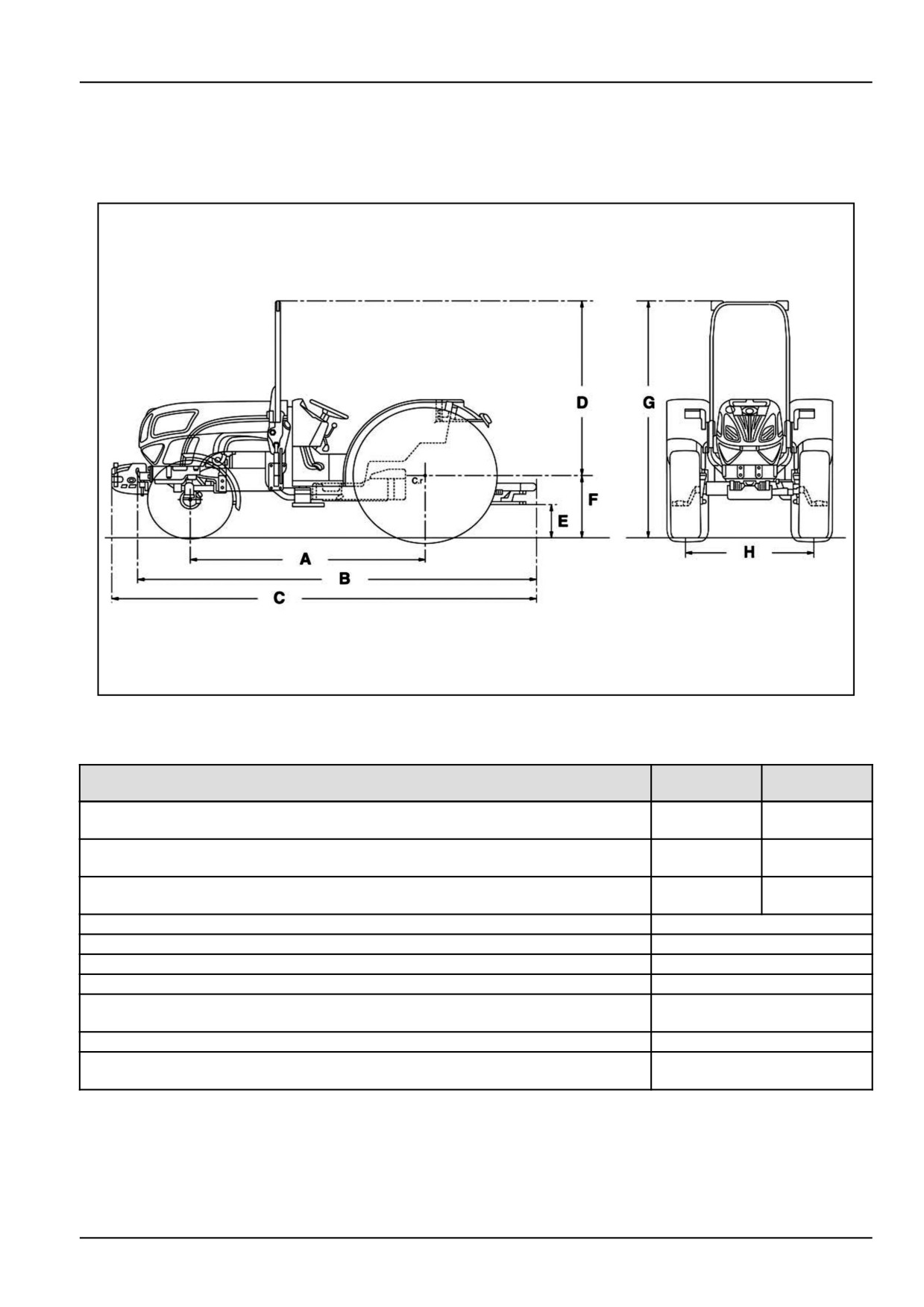
9 - SPECIFICATIONS
9 - SPECIFICATIONS###_9_###
Dimensions and weights
DCSPVNEGB001S9F
1
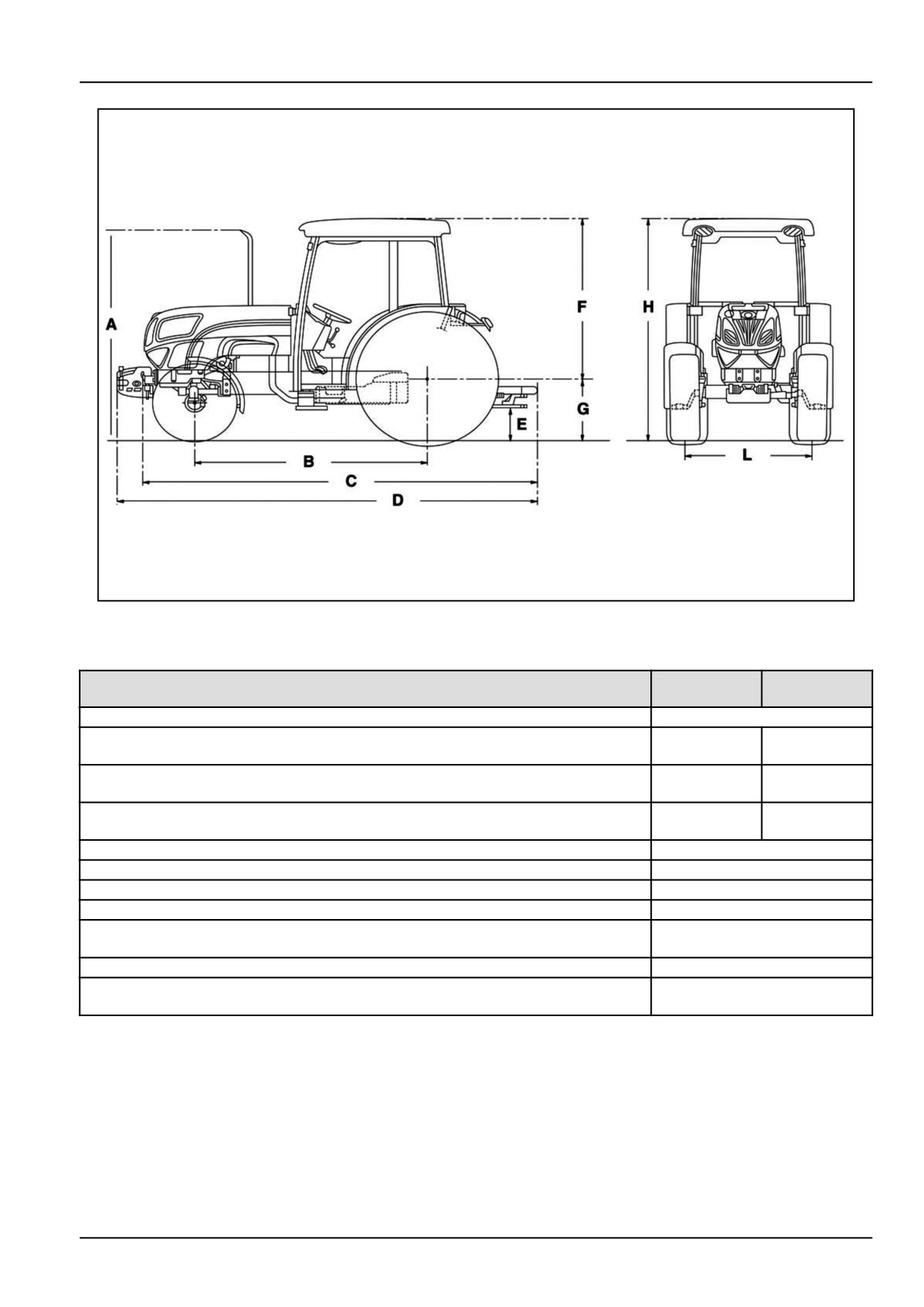
Dimensions of 2WD models without cab
T4.75F -
T4.95F -
Dimensions
T4.85F
T4.105F
2082.5 mm
2169.5 mm
A
(82.0 in)
(85.4 in)
3682 mm
3769 mm
B
(145.0 in)
(148.4 in)
3914.5 mm
4001.5 mm
C
(154.1 in)
(157.5 in)
D
1749.5 mm (68.9 in)
E
323 mm (12.7 in)
F - min. with 380/70 R 20
525 mm (20.7 in)
F - max with 420/70 R 30
675 mm (26.6 in)
2274.5 - 2424.5 mm (89.5 -
G
95.5 in)
H - front track setting
1146 - 1572 mm (45.1 - 61.9 in)
1058 - 1371 mm (41.7 -
H - rear track setting
54.0 in)
9-1
9 - SPECIFICATIONS
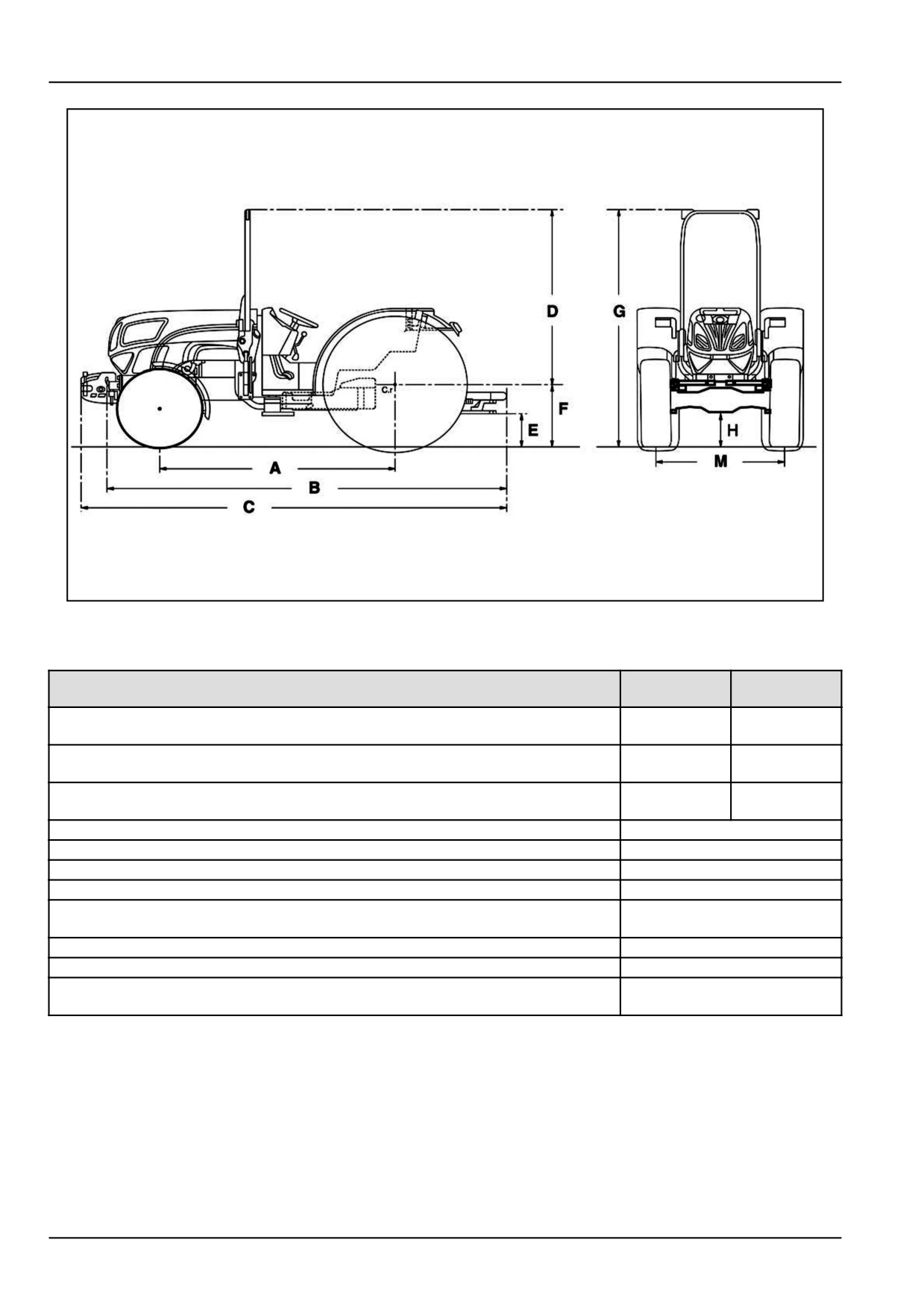
DCSPVNEGB003S9F
2
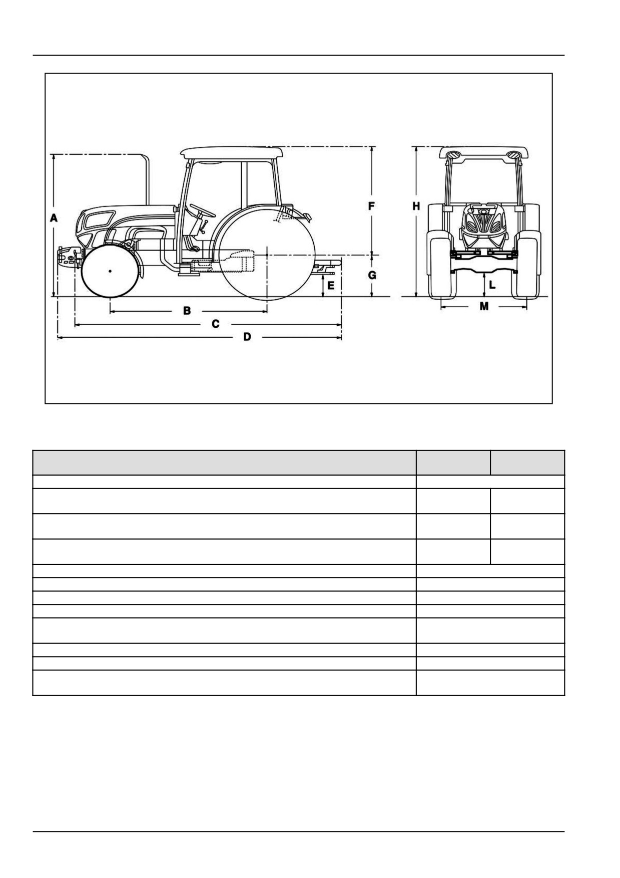
Dimensions of 4WD models without cab
T4.75F -
T4.95F -
Dimensions
T4.85F
T4.105F
2348 mm
2435 mm
A
(92.4 in)
(95.9 in)
3947.5 mm
4034.5 mm
B
(155.4 in)
(158.8 in)
3914.5 mm
4001.5 mm
C
(154.1 in)
(157.5 in)
D
1749.5 mm (68.9 in)
E
323 mm (12.7 in)
F - min. with 380/70 R 20
525 mm (20.7 in)
F - max with 420/70 R 30
675 mm (26.6 in)
2274.5 - 2424.5 mm (89.5 -
G
95.5 in)
H
331 mm (13.0 in)
M - front track setting
1190 - 1492 mm (46.9 - 58.7 in)
1058 - 1371 mm (41.7 -
M - rear track setting
54.0 in)
9-2
9 - SPECIFICATIONS
DCSPVNEGB002S9F
3
Dimensions of 2WD models with cab
T4.75F -
T4.95F -
Dimensions
T4.85F
T4.105F
A
2161 - 2311 mm (85.1 - 91.0 in)
2082.5 mm
2169.5 mm
B
(82.0 in)
(85.4 in)
3682 mm
3769 mm
C
(145.0 in)
(148.4 in)
3914.5 mm
4001.5 mm
D
(154.1 in)
(157.5 in)
E
323 mm (12.7 in)
F
1648 mm (64.9 in)
G - min. with 380/70 R 20
525 mm (20.7 in)
G - max with 420/70 R 30
675 mm (26.6 in)
2173 - 2323 mm (85.6 -
H
91.5 in)
L - front track setting
1146 - 1572 mm (45.1 - 61.9 in)
1058 - 1371 mm (41.7 -
L - rear track setting
54.0 in)
9-3
9 - SPECIFICATIONS
DCSPVNEGB004S9F
4
Dimensions of 4WD models with cab
T4.75F -
T4.95F -
Dimensions
T4.85F
T4.105F
A
2161 - 2311 mm (85.1 - 91.0 in)
2348 mm
2435 mm
B
(92.4 in)
(95.9 in)
3682 mm
3769 mm
C
(145.0 in)
(148.4 in)
3914.5 mm
4001.5 mm
D
(154.1 in)
(157.5 in)
E
323 mm (12.7 in)
F
1648 mm (64.9 in)
G - min. with 380/70 R 20
525 mm (20.7 in)
G - max with 420/70 R 30
675 mm (26.6 in)
2173 - 2323 mm (85.6 -
H - min.
91.5 in)
L
240 - 331 mm (9.4 - 13.0 in)
L - front track setting
1190 - 1492 mm (46.9 - 58.7 in)
1058 - 1371 mm (41.7 -
L - rear track setting
54.0 in)
9-4
9 - SPECIFICATIONS
FRONT BALLAST
Each plate
25 kg (55.12 lb)
Max. 6 plates
Each plate
40 kg (88.2 lb)
Max. 6 plates
REAR BALLAST
Each ring
Rims 28 " — 30 "
50 kg (110.2 lb)
Max. 4 rings
Each ring
Rims 24 "
32 kg (70.5 lb)
Max. 6 rings
WEIGHTS OF 2WD TRACTORS WITHOUT CAB WITHOUT BALLAST WEIGHTS
T4.75F ● T4.85F
2762 kg (6089.2 lb)
T4.95F ● T4.105F
2842 kg (6265.5 lb)
WEIGHTS OF 4WD TRACTORS WITHOUT CAB WITHOUT BALLAST WEIGHTS
T4.75F ● T4.85F
2832 kg (6243.5 lb)
T4.95F ● T4.105F
2912 kg (6419.9 lb)
WEIGHTS OF 2WD TRACTORS WITH CAB WITHOUT BALLAST WEIGHTS
T4.75F ● T4.85F
2840 kg (6261.1 lb)
T4.95F ● T4.105F
2930 kg (6459.5 lb)
WEIGHTS OF 4WD TRACTORS WITH CAB WITHOUT BALLAST WEIGHTS
T4.75F ● T4.85F
Standard axle 2910 kg (6415.5 lb)
T4.95F ● T4.105F
Standard axle 3000 kg (6613.9 lb)
9-5
9 - SPECIFICATIONS
Maximum permitted loads on front and rear axle
WARNING
Overturning hazard!
The operator must know the correct OPERATING LOAD capacity of the machine before attempting to
operate the machine. Always follow the recommended load limits.
Failure to comply could result in death or serious injury.
W0216A
NOTICE: The total weight of the tractor, including the ballast and the weight of the implements carried, must not
exceed the limits given in the table below. The values refer to the axle capacity.
Maximum permissible weight for road transport
Maximum front axle load
Maximum rear axle load
Total maximum load
2WD — 3900 kg (8598 lb)
2000 kg (4409 lb)
3500 kg (7716 lb)
4WD — 4300 kg (9480 lb)
ATTENTION: If the value of the maximum load of the pair of tires is less than the maximum axle load it is necessary
to refer, for the maximum load, to the value of the pair of tires. Otherwise it is necessary to take the axle load as the
maximum load.
9-6
9 - SPECIFICATIONS
Maximum permitted loads on drawbar
The maximum vertical load of the drawbar is given in the table below:
Bar model
Maximum vertical load
694.142.001
490 kg (1080 lb)
CUNA-type drawbar — For the ITALIAN market only
Vertical loading is not permissible. Single-axle trailers are not permissible.
9-7
9 - SPECIFICATIONS
Technical data
ENGINE SPECIFICATION
T4.75F
F5A E9484 B*A 001
T4.85F
F5A E9484 G*A 006
T4.95F
F4C E9484 M*J 603
T4.105F
F4C E9484 L*J 603 ● F4C E9484 L*J 602
Clutch
11 "
injection pump
BOSCH
Intake
Turbocharger + intercooler
Number of cylinders
4
Injection Sequence
1−3−4−2
T4.75F● T4.85F - 99 mm (3.90 in) x 104 mm (4.09 in)
Bore and stroke:
T4.95F ● T4.105F - 104 mm (4.09 in) x 132 mm (5.20 in)
T4.75F● T4.85F - 3200 cm³ (195.28 in³)
Total displacement
T4.95F ● T4.105F - 4485 cm³ (273.69 in³)
T4.75F● T4.85F - 18 : 1
Compression ratio
T4.95F ● T4.105F - 17.5 : 1
Maximum horsepower (ECE R120)
T4.75F
57 kW (77 Hp)
T4.85F
65 kW (88 Hp)
T4.95F
71 kW (97 Hp)
T4.105F
79 kW (107 Hp)
Torque Rise
T4.75F
39 %
T4.85F
30 %
T4.95F
35 %
T4.105F
30 %
Rated Speed
2300 RPM
Maximum torque
1300 RPM
FUEL SYSTEM
Double-diaphragm fuel pump on injection pump supply line.
Rotary injection pump with centrifugal speed governor, operating at all speeds and incorporating automatic
advance: BOSCH-VE4
Fuel filtering:
- mesh filter in the fuel pump
- replaceable cartridge filter on the injection pump feed line with water separator. Fuel sedimenter filter (on request).
LUBRICATION
Forced, by gear pump.
Oil filtration: forced through pump intake mesh and replaceable cartridge filter on engine intake.
Lubrication pressure with engine RPM of 2300 RPM: 2.9 - 3.9 bar (42.1 - 56.6 psi)
Engine oil cooled by a heat exchanger using engine coolant.
COOLING
Water, forced circulation by centrifugal pump
Radiator with 3 lines of vertical copper pipes for T4.75F - T4.85F models and 4 lines of vertical copper pipes for
mod. T4.95F - T4.105F.
Cooling fan fitted on same shaft as water pump.
9-8
9 - SPECIFICATIONS
COOLING
Water circulation from engine to radiator thermostatically controlled.
TRANSMISSION
Dry 11" double-plate clutch, with separate controls: pedal operation for gearbox and hand lever for power take-off.
Plate material - manual transmissions: metal-ceramic
Plate material - electro-hydraulic transmissions: organic
PTO clutch: metal-ceramic
Transmission housing
Permanently engaged helical mesh with 4 gear ratios.
Full syncromesh for all gears.
Range gear: Standard cascade connection with 4 gear ranges and synchronised mechanical shuttle.
Range gear: On request cascade connection with 4 gear ranges, Power-Shuttle/dual command (2 speed power
shift) device and electro-hydraulic shuttle and creeper unit.
Range gear: On request cascade connection with 4 gear ranges, Power-Shuttle/dual command (2 speed power
shift) device and mechanical shuttle.
Rear transmission
Bevel gear pair ratios:
30 km/h (18.64 mph)
9/38
30 km/h (18.64 mph) with 20 " rear tyres
11/36
40 km/h (24.9 mph) with standard front axle
11/36
40 km/h (24.9 mph)
11/32
Differential with pedal-operated mechanical locking device or electrohydraulic locking device with automatic
release. Epicyclic final drives.
9-9
9 - SPECIFICATIONS
REAR POWER TAKE-OFF
Completely independent with two speeds 540/1000 RPM.
Engine speed:
PTO speed:
Engine speed:
PTO speed:
2196 RPM
540 RPM
2300 RPM
565 RPM
2260 RPM
1000 RPM
2300 RPM
1017 RPM
Manual control: clutch control lever, take-off engage lever and speed selector lever. Direction of rotation with tractor
seen from behind: clockwise.
FRONT POWER TAKE OFF
Manual control with knob for electromagnetic clutch. Fully independent at 1000 rpm. Direction of rotation with
tractor seen from the front: anticlockwise.
Engine speed:
PTO speed:
2037 RPM
1000 RPM
2300 RPM
1032 RPM
MECHANICALLY OR ELECTRONICALLY CONTROLLED REAR HYDRAULIC LIFT
Oil supply is from the transmission by gear pump operated directly by the engine:
NEW HOLLAND TYPE C42
BOSCH TYPE 25
pump speed with engine on full power: 2502 RPM
rated flow rate with engine on full power:
NEW HOLLAND TYPE C42 (standard) 48,6 l/min
BOSCH TYPE 25 (on request) 63,8 l/min
pressure relief valve calibration: 190 bar (2755 psi)
Maximum rear lift capacity
With third point connected to top hole of support bracket and for the entire lifting stroke:
at link ends of horizontal arms
1835 kg (4045 lb)
with centre of gravity at 610 mm (24.02 in) from link ends
1715 kg (3781 lb)
Maximum front lift capacity
With third point connected to top hole of support bracket and for the entire lifting stroke:
at link ends of horizontal arms
1275 kg (2810.9 lb)
with centre of gravity at 610 mm (24.02 in) from link ends
980 kg (2160.5 lb)
THREE POINT HITCH
1st and 2nd category three-point implement linkage device.
Stabilisers for all models:
− mechanically adjusted telescopic stabiliser struts (standard).
− hydraulically adjusted telescopic stabiliser struts (on request).
Link arms with rapid attachment (on request).
Single or double-acting rear mount remote valves: up to three, two with float and automatic release.
Single or double-acting rear mount remote valves: two with flow rate control (on request).
Front 3-Point Hitch
1st and 2nd category three-point implement linkage device.
9-10
9 - SPECIFICATIONS
FRONT AXLE
Central pivoting, telescopic, inverted "U" structure.
Track setting: by extending the axle. Total: 5 wheel tracks.
2WD FRONT WHEELS
Rims with integral sheet metal wheel disks.
4WD FRONT WHEELS
Wheels in two parts: sheet-metal wheel disc and tyre rim.
Track setting: variable fitting of rims to disks and wheel hubs.
REAR WHEELS
Wheels in two parts: sheet-metal wheel disc and tyre rim.
Track setting: variable fitting of rims to disks and wheel hubs.
STEERING SYSTEM
Hydrostatic control, independent circuit.
Metal cartridge oil filter, fitted in oil reservoir.
Gear pump operated directly by the engine, through timing gears:
Type NEW HOLLAND
with mechanical transmissions
A25
with electro-hydraulic transmissions
A31 XRP2
pump speed with engine on full power:
2502 RPM
corresponding flow :
With pump A25
28 l/min
With pump A31 XRP2
35.6 l/min
pressure relief valve calibration - models
170 bar (2465.0 psi)
Minimum turning radius not brake assisted:
3.4 m (133.86 in)
Minimum turning radius brake assisted:
3.1 m (122.05 in)
4WD FRONT AXLE
Controlled oscillation with co-axial drive shaft and pivoting on the longitudinal axis of the tractor.
Differential
with two planetary pinions.
Transmissions with spur gears. Epicyclic reduction gears on wheel hubs with braking system (on request).
Standard front axle
Bevel gear pair ratios 30 km/h (18.64 mph)
11/36
Bevel gear pair ratios 40 km/h (24.9 mph)
11/28
with 20 " rear tyres
13/37
Bevel gear pair ratios 30 km/h (18.64 mph)
-
Bevel gear pair ratios 40 km/h (24.9 mph)
10/29
Minimum turning radius not brake assisted, four-wheel drive disengaged, four-wheel drive models:
not brake assisted
3.3 m (129.92 in)
brake assisted
3.2 m (125.98 in)
REAR SERVICE BRAKES
Oil-immersed disk brakes, hydrostatically operated with independent hydraulic circuits for right and left-hand
brakes, operated by separate pedals. The pedals must be connected for simultaneous braking on the four wheels
when driving on roads.
FRONT SERVICE BRAKES
Oil-immersed disk brakes, hydrostatically operated. The pedals must be connected for simultaneous braking on
the four wheels when driving on roads.
PARKING BRAKE ON TRANSMISSION
Disk brake, fully independent, mounted beneath gearbox and connected to pinion shaft.
Mechanically operated by lever.
9-11

9 - SPECIFICATIONS
BODYWORK AND DRIVING POSITION
With roll bar
Platform, instrument panel and mudguards form a single, modular structure, suspended on 4 silent blocks. Sheet
metal mudguards coated with a layer of zinc, adjustable in height.
Mounting structure for roll bar.
Two fuel tanks with single filler cap, one of which located on the right-hand side beneath cab and the other
located in front of the radiator.
Back folding bonnet, held in the open position by a rigid support rod.
Models with cab
Mudguards and cab form a single integrated structure. Two fuel tanks with single filler cap, one of which located
on the right-hand side beneath cab and the other located in front of the radiator.
Back folding bonnet, held in the open position by a rigid support rod.
SEAT
Padded, with mechanical suspension, adjustable springing and position.
TOWING DEVICES
Cross member with attachment holes.
Rear swinging drawbar.
Rear height-adjustable rigid hook.
Front manoeuvring hook.
ELECTRICAL SYSTEM
Voltage
12 V
ALTERNATOR
Magneti Marelli with incorporated electronic voltage
120 A
regulator
Maximum horsepower with engine at 2300 RPM,
1.4 kW
approximately
BATTERY
12 V - Capacity (amperage) 88/100 A, sealed, maintenance-free.
Starter
With electromagnet coupling:
T4.75F - T4.85F
3.2 kW
T4.95F - T4.105F
4.2 kW
LIGHTS
Two asymmetrical front headlamps using 55 W bulbs (white or yellow)
Two front light clusters including:
- position lights ( 5 W light bulb) with clear transparent cover;
- direction indicator ( 21 W light bulb) with orange transparent cover;
Two rear light clusters including:
- position lights ( 5 W light bulb) with red transparent cover;
- direction indicator ( 21 W light bulb) with orange transparent cover;
- brake light ( 21 W light bulb) with red transparent cover;
- number plate light.
Red rear reflectors.
INSTRUMENTS AND ACCESSORIES
Multiple function (multifunction) instrument cluster
7-pin DIN power socket.
25 A power socket.
Flashing hazard warning light indicator for tractor and trailer.
Cold start aid (grid heater).
9-12
10 - ACCESSORIES
10 - ACCESSORIES###_10_###
Radio
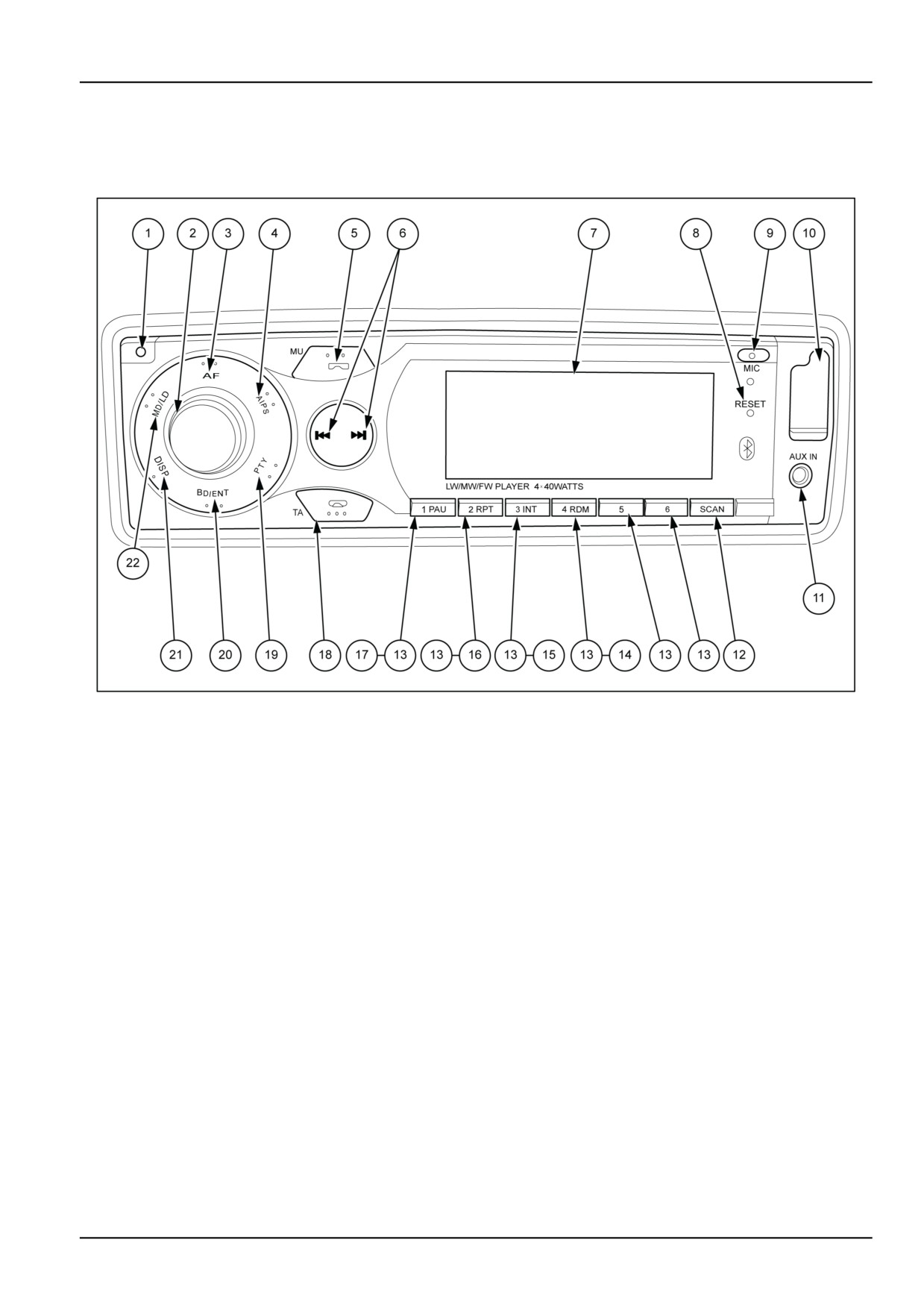
MOIL13TR00770FA
1
1.
Power ON/OFF button
Press to turn on the radio. Press and hold to turn OFF.
2.
Function/volume selection knob
Turn the knob (to the right/left) to regulate “VOL/BAS/TRE/BAL/FAD”. To select other functions, press the button
until the desired function is shown on the display.
3.
Alternative frequency selection button (AF7REG)
When pressed momentarily, AF/REG mode is selected. When “AF/REG” mode is selected, the radio checks the
signal strength of the AF all the time. When pressed long, it is activated as regional mode ON/OFF.
4.
Automatic tuning button (A/PS)
A - By pressing longer than 1 sec, the 6 strongest stations are stored in the corresponding preset memory number.
When Automatic Scan operation (AS) is finished, the radio executes the preset scan.
PS By pressing shortly, the radio searches for each preset station. Each preset station will be played for 5 sec-
onds.
5.
Audio stop button (MU) and call answering
Press this button to turn off the sound. Press it again to return to the previous volume level.
6.
Automatic or manual tuning selection
When pressed momentarily, these buttons generate an Automatic Scan. When pressed longer than 1 sec., they
activate a Manual Scan.
In the MP3/WMA player mode, when pressed briefly these buttons activate the track up or track down mode.
When pressed for longer than a second they activate the CUE mode (addition of indexes) or REVIEW (reviewing)
7.
Information "LCD" display
The Liquid Crystal Display will display the current state of the unit. The auxiliary input jack (AUX IN) allows easy
connection of portable media devices.
8.
Button to reset settings “RESET”
10-1
10 - ACCESSORIES
The Reset button is on the housing. The Reset button is to be activated for one of the following reasons:
− Initial installation of the unit when all wiring is completed.
− None of the buttons function.
− Error symbol on the display.
9.
Microphone for speakerphone conversation (Bluetoot)
10.
USB Port
Using USB cable to connect your portable MP3 player.
NOTE: Using USB cable to connect your portable MP3 player.
11.
“AUX IN” input
12.
Automatic scanning to search for radio channels and recording (SCAN/REC)
Press SCAN button to activate radio scan. The unit will search for every station and will play 5 seconds of each
station found. To cancel scanning, press the button once more.
13.
Selection buttons for stations 1-2-3-4-5-6
When pressed momentarily, these buttons directly select the station saved on the button. If pressed for longer
than 1 second, the station tuned to at that moment is saved.
In player mode MP3/WMA
M5 — Folder up
M6 — Folder down
14.
RANDOM button (for USB playback only)
When this button is pressed, the “RDM ON” indication is displayed and each track is played in random instead
of normal progression. To cancel Random mode, press the “ RDM” button again.
15.
INTRO (INT) button (for USB playback only)
When this button is pressed, the “INT ON” indication is displayed and the first several seconds of each track is
played. Press again to stop intro and listen to track.
16.
REPEAT (RPT) button (for USB playback only)
Repeat the track. When this button is pressed the display shows “RPT ON” and the repetition of the selected
track will be repeated continually until the "repeat track" is cancelled by pressing the (RPT) button again.
17.
PAUSE (PAU) button (for USB playback only)
During playback, press the button to pause. Press it again to resume play.
18.
Button for traffic information and end of call (TA)
When pressed briefly, “TA” mode on or off is selected When “TA” mode is selected and a traffic announcement
is transmitted - If the level of the volume is under the listening threshold, it is raised up to this threshold. When
a “TP” station is received, “TP” is shown on the display.
19.
Program type button (PTY)
When pressed momentarily, the “PTY” ON/OFF function is activated and the search starts for the “PTY” infor-
mation, that stops when the corresponding “PTY” information is detected. By pressing this key longer than 2
sec., you can select “PTY” mode by turning the volume knob as below.
NEWS--AFFAIRS--INFO--SPORT--EDUCATE--
DRAMA--CULTURE--SCIENCE--VARIED--POP--ROCK-
-EASY−M--LIGHT−M--CLASSIC
OTHER−−M--WEATHER--FINANCE--CHILDREN--SOCIAL--RELI-
GION--PHONE
IN--TRAVEL--LEISURE--JAZZ--COUNTRY--NATION.−M--OLDIES--FOLK
M--DOCU-
MENT--TEST--ALARM.
20.
Button to select band and enter (BD/ENT)
(RDS: for Europe) Press this button consecutively to switch in sequence through the bands “ FM1--FM2--FM3--
MW1--MW2--LW” .
21.
DISPLAY button
Press the “DISP” button to switch between display information such as radio frequencies, clock, track and other
information depending on the play mode.
22.
MODE/LOUDNESS button (MD/LD)
By pressing this button, the user can select “AUX/TUNER/USB/AD2P” modes.
Connecting to a Portable MP3 Player
Use the USB cable to connect your portable MP3 player to port (10).
The external audio input jack (11) “AUX IN” enables connecting to a portable device.
10-2
10 - ACCESSORIES
How to select MP3/WMA files
Searching by track number
• Press (4) (A/PS) to activate track search.
• Turn the volume knob (2) to the left or right to select the first digit desired.
• Press the volume knob (2), the first digit is saved and the second one starts blinking.
• Turn the volume knob (2) to the left or right to select the second and third digit.
• Press button (21) (BD/ENT); the selected track will automatically be played back.
Searching by letter:
• Pressing (4) (A/PS) twice activates track searching by character.
• Turn the volume knob (2) to the left or right to select the desired letter.
• Press the volume knob (2), and repeat the previous step to select the second and third
letter.
• Songs with the same letters that were previously selected appear on the display
• Turn the volume knob (2) to the left or right to select the desired track.
• Press button (21) (BD/ENT); the selected track will automatically be played back.
Searching by file name:
• Pressing (4) (A/PS) three times activates track searching by folder.
• Turn the volume knob (2) to the left or right to select the desired folder.
• Press button (21) (BD/ENT); the folder is saved and the first file will automatically be played back.
Recording / Storing / Deleting on a USB Memory Stick
You can store recordings from the tuner (radio) on an USB memory stick. The recordings are made in the same order
and end automatically when the memory is completely full
Recording from the radio
• Insert a USB memory stick into the USB port (10).
• Press button (22) MD/LD to select playing the PLL Band radio.
Starting Recording
• Hold down button (12) SCAN/REC for two seconds; REC USB will appear on the display.
• Press button (20) BD/ENT; the display will show RECORD . Then the letter R appears (flashing), followed by infor-
mation on the storage location (e.g. 01 ) and the length of the recording (e.g. 19.58 )
Stopping Recording
• Press button (20) BD/ENT
Deletion
• Use button (22) MD/LD to select mode USB . Track playback begins.
• Hold down button (12) SCAN/REC for two seconds.. The display shows DELETE.
• Press button (20) BD/ENT. The current track is deleted automatically.
Connecting iPod
You can connect your portable iPOD device and play songs from the vehicle stereo. Only the audio feature is sup-
ported, other features of iPOD are not supported.
It is possible to play songs from the iPOD when the cable is connected properly.
• Repeatedly press button (22) MD/LD until the display shows IPOD.
• Press button (4) A/PS
10-3
10 - ACCESSORIES
• Turn knob (2) VOL (left/right) to select PLAYLIST - ARTISTS - ALBUMS - SONGS - GENRES - COMPOSER
• Press SEL.
If you are aware on how to use iPOD, the way to use the vehicle stereo feature is basically just the same. Take note
of the equivalent key function below.
Radio
iPOD
Function
Turn the VOL knob (left/right)
Turn click wheel
Up/down category/file browsing
Press the VOL knob
Press button SELECT
Selecting a category / Play song
NOTE: Please refer to your iPOD user’s manual for operating instructions. Press A/PS to return to the main menu.
How to use BLUETOOTH in your vehicle audio system
Before you can dial out from the vehicle stereo, you must first pair (PAIRING) the phone with the radio. This
”pairing” is a procedure for connecting two devices equipped with Bluetooth.
1. This unit’s Bluetooth function is always on, perform the pairing starting from your cellular phone. Refer to your
cellular manual on proper pairing
2. Perform the search for available Bluetooth devices, “CAR--BT” will show. Enter 0000 when the code is re-
quested.
3. After successful pairing, connect to the head unit if it is not automatically connected.
How to make / receive calls using the front panel
To make calls using call history
• Press and hold button (5) to display the “REDIAL” history.
• Turn repeatedly to select the telephone number to call and press button (5) to start the call.
• During conversation, press button (18) to end the call.
• When there is incoming call, press button (5) to receive the call.
• Press button (18) to reject the call.
Audio Streaming
If your phone is “A2DP” format compatible, you can play music from your mobile and the music will be transferred
to the vehicle audio system
1. Make sure your mobile and the vehicle radio unit is paired and connected.
2. Play the music in your mobile according to your mobile operating method.
3. The unit will display “A2DP” when receiving A2DP automatically (but for some mobiles your have to press the
MODE button to change A2DP mode).
4. You can press buttons (6) on the unit for the previous or next tracks.
CHARACTERISTICS
PLAYER MP3/WMA
Signal to Noise ratio
> 60 dB
Channel separation
> 50 dB (1kHz)
Channel separation
20Hz - 20 kHz
Radio (FM) — (RDS)
Frequency range
87,5 - 107,9 MHz
Channel step
200 kHz
Intermediate frequency
10,7 MHz
Sensitivity
2,8 μV
Stereo separation
30 dB
Signal to Noise ratio
50 dB
Radio MW (AM
10-4

10 - ACCESSORIES
522 - 1620 MHz with RDS
Frequency range
522 - 1710 MHz without RDS
Intermediate frequency
10,71 MHz
Sensitivity
32 dB
Radio LW
Frequency range
144 - 290 MHz
Intermediate frequency
10,71 MHz
Line out
Output
5 V (max)
Impedance
10k Ohm
General data
Power
12 V DC ( 10.8 - 15.6 V enabled
Speaker impedance
4—8 Ω
Output power
40 W x 4 CH
NOTE: Specifications and design are subject to possible modification without notice due to improvement.
Disposal
This product bears the selective sorting symbol for waste electrical and electronic equipment (WEEE).
This means that this product must be handled pursuant to European Directive 2002/96/EC in order to be recycled or
dismantled to minimize its impact on the environment.
For further information, please contact your local or regional authorities. Electronic products not included in the selec-
tive sorting process are potentially dangerous for the environment and human heath due to the presence of hazardous
substances.
10-5