New Holland Boomer 41, Boomer 47 Compact Tractor. OPERATOR’S MANUAL (2014) - page 4
4 - OPERATING INSTRUCTIONS
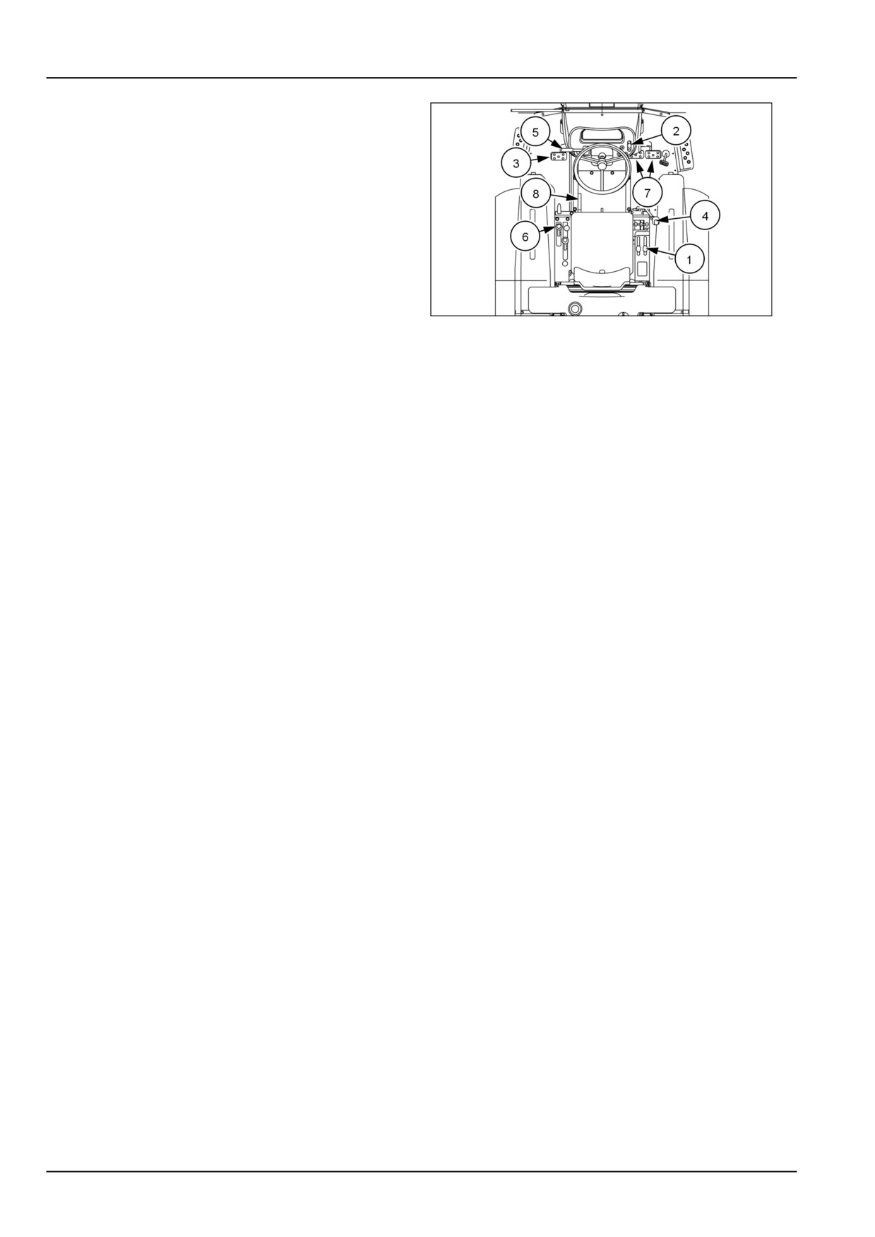
To operate the 16 x 16 gear transmission, carry out the
following:
1. Start the engine and pull the HPL control lever (1) rear-
ward to lift the implement off the ground (if equipped).
2. Move the hand throttle lever (2) forward until the en-
gine speed is above 1500 RPM.
3. Depress the clutch pedal (3) fully.
4. Place the main transmission shift lever (4) shuttle shift
lever (5) and range lever (6) into the desired position.
5. Depress the brake pedals (7) and disengage the park
brake lever (8).
93100852
5
6. Release the clutch pedal (3) slowly, and the tractor will
start to move.
NOTE: Release the clutch pedal slowly, if the clutch pedal
is released fast it will cause the tractor to move suddenly.
NOTE: To change 1-4 gears depress the clutch pedal fully
and shift into the desired gear and release the clutch pedal
slowly.
4-34
4 - OPERATING INSTRUCTIONS
PARKING THE UNIT
Brakes and controls - Park
Gear model
WARNING
Avoid injury! Always do the following before
lubricating, maintaining, or servicing the ma-
chine.
1. Disengage all drives.
2. Engage parking brake.
3. Lower all attachments to the ground, or
raise and engage all safety locks.
4. Shut off engine.
5. Remove key from key switch.
6. Switch off battery key, if installed.
7. Wait for all machine movement to stop.
Failure to comply could result in death or se-
rious injury.
W0047A
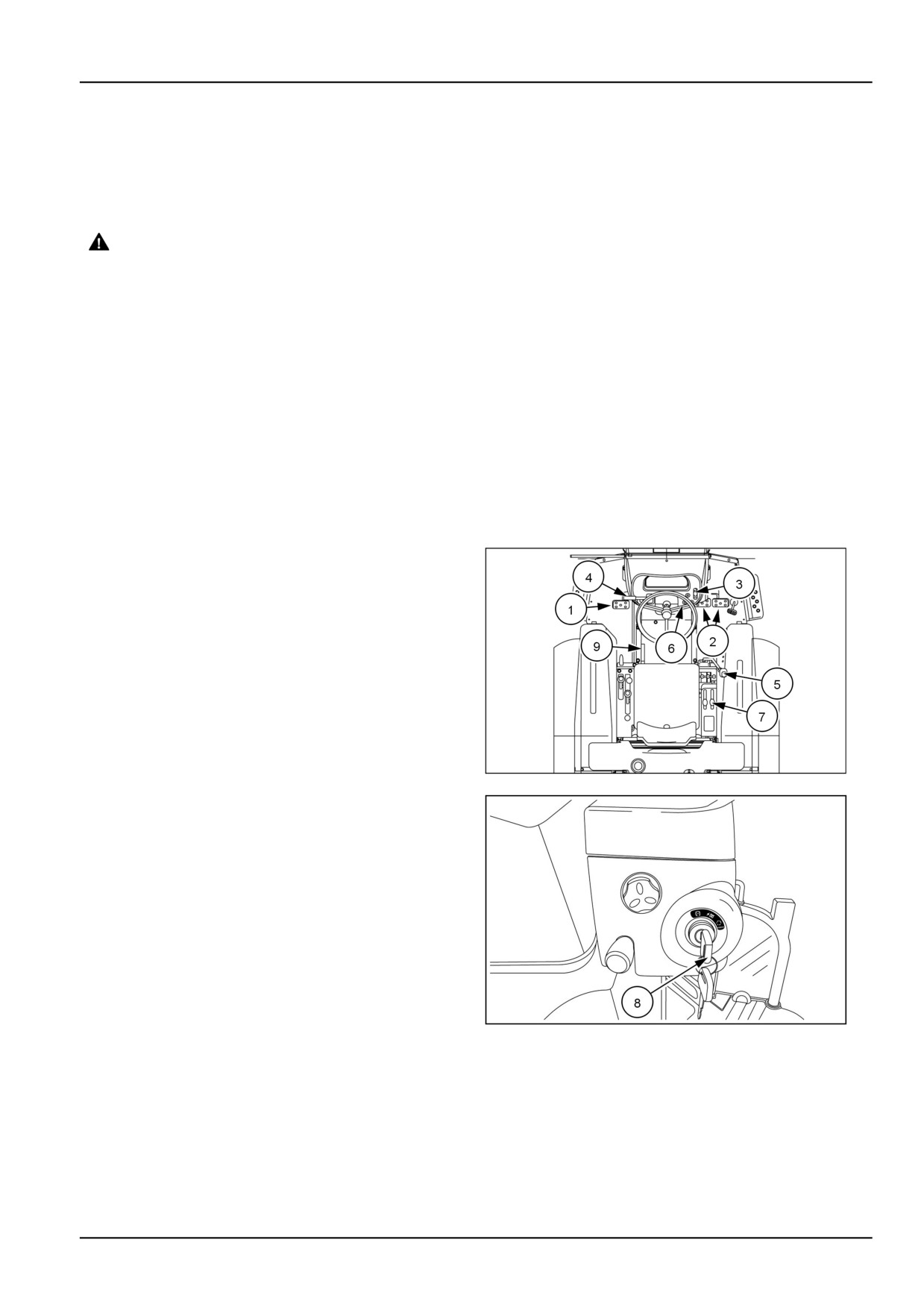
To park the tractor carry out the following procedures:
1. Depress the clutch pedal (1) and brake pedals (2).
Pull the hand throttle lever (3) rearward to reduce the
engine speed.
NOTE: Park the tractor on a level surface, if it is neces-
sary to park on a slope, place the transmission in the
lowest gear and place chocks or blocks in front or be-
hind the tires depending on the direction of the slope.
2. Place the shuttle shift lever (4) main gear shift lever (5)
in neutral and make sure the PTO switch (6) is in the
"OFF" position.
3. Push the HPL control lever (7) forward to lower imple-
ments (if equipped) to the ground. Turn the key (8) to
93100852
1
the "STOP" position.
4. Engage the park brake (9) and release the brake ped-
als and clutch pedal slowly.
NHIL13CT01006AA
2
4-35
4 - OPERATING INSTRUCTIONS
HST model
WARNING
Avoid injury! Always do the following before
lubricating, maintaining, or servicing the ma-
chine.
1. Disengage all drives.
2. Engage parking brake.
3. Lower all attachments to the ground, or
raise and engage all safety locks.
4. Shut off engine.
5. Remove key from key switch.
6. Switch off battery key, if installed.
7. Wait for all machine movement to stop.
Failure to comply could result in death or se-
rious injury.
W0047A
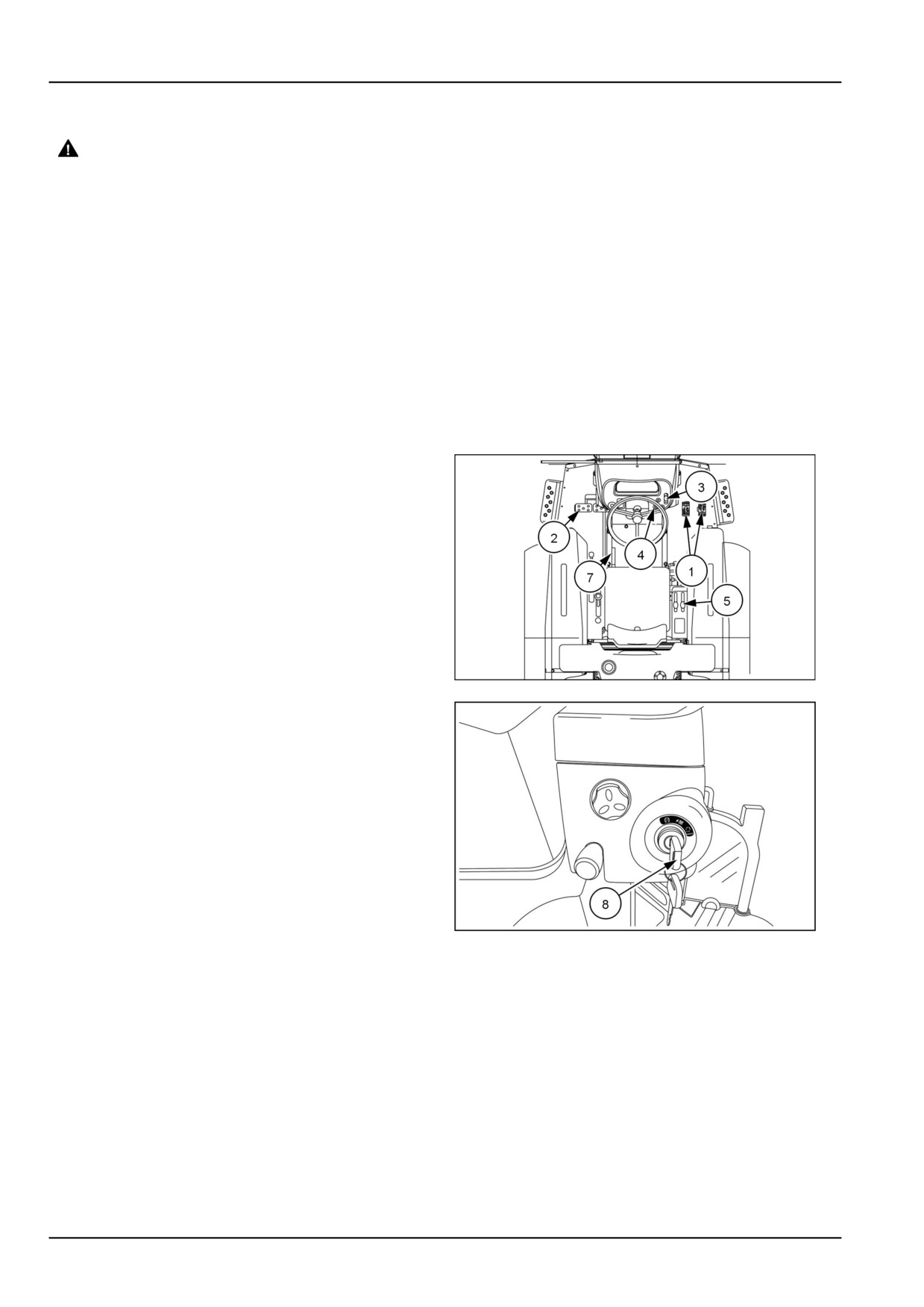
To park the tractor carry out the following procedures:
1. Release the HST forward or reverse pedal (1) slowly
and depress the brake pedals (2). Pull the hand throt-
tle lever (3) rearward to reduce the engine speed.
NOTE: Park the tractor on a level surface, if it is nec-
essary to park on a slope, place the range gear shift
lever in the lowest gear and place chocks or blocks in
front or behind the tires depending on the direction of
the slope.
2. Make sure the PTO switch (4) is in the "OFF" position.
3. Push the HPL control lever (5) forward to lower imple-
ments (if equipped) to the ground. Turn the key (6) to
the "STOP" position.
93100853
3
4. Engage the park brake (7) and release the brake ped-
als slowly.
NHIL13CT01006AA
4
4-36
5 - TRANSPORT OPERATIONS
5 - TRANSPORT OPERATIONS###_5_###
ROAD TRANSPORT
External lighting - Identification
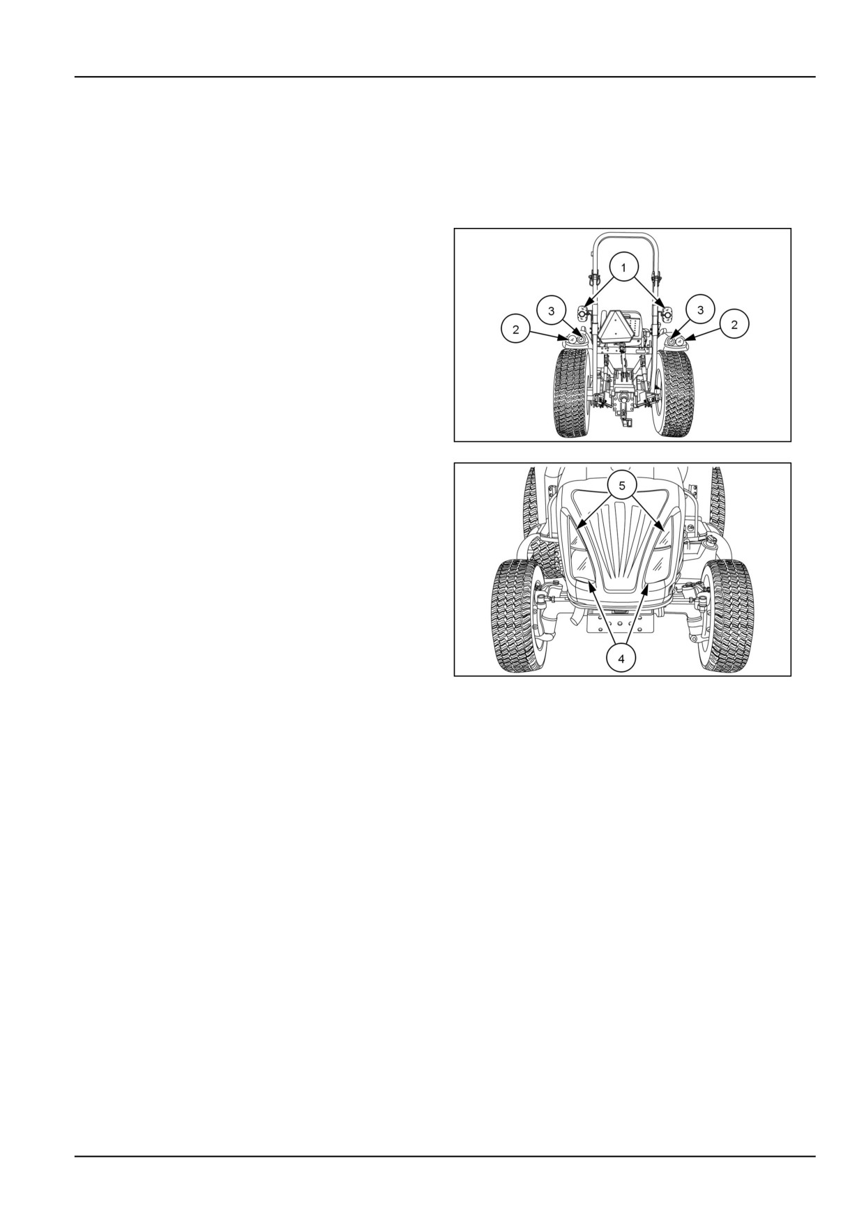
Your tractor is equipped with:
• Turn signal/hazard side warning lights (1).
• Rear amber warning lights (2)
• Rear red tail/brake lights (3).
• Road lights (4) Work Lights (5).
• Rear Work Light (Optional) mounted on the rear of the
ROPS.
NHIL13CT01167AA
1
NHIL13CT01166AA
2
5-1
5 - TRANSPORT OPERATIONS
Hazard warning light operation
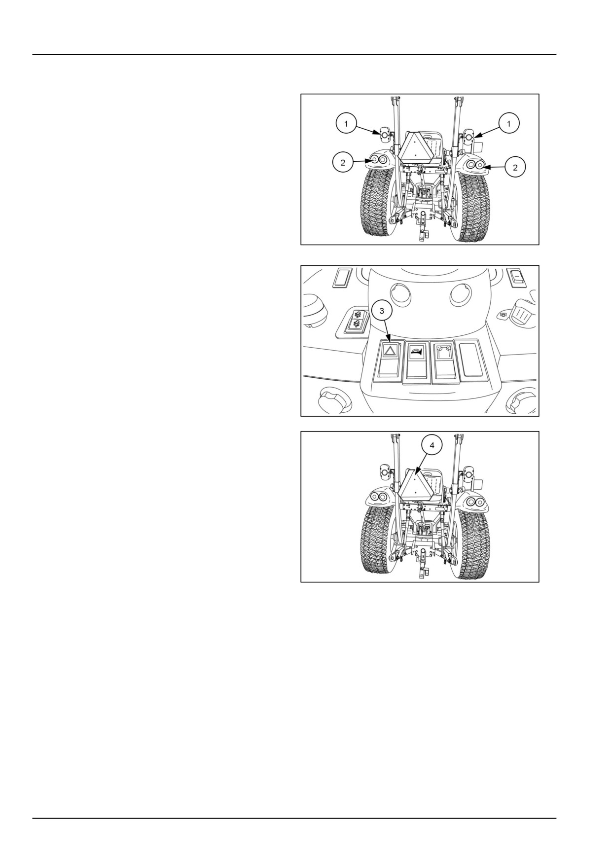
The side hazard warning lights (1) and tail amber lights
(2) are activated by hazard rocker switch (3) located in
the center of the steering column shroud.
NOTE: The hazard lights can function with the key switch
in any position.
NHIL13CT01013AA
1
1. To activate the hazard lights push the rocker switch (3)
down.
NOTE: For your protection, use the hazard warning lights,
the SMV (Slow Moving Vehicle) sign (4) and road lights
when traveling on public roads, day or night.
NHIL13CT01004AA
2
NHIL13CT01013AA
3
5-2
5 - TRANSPORT OPERATIONS
Turn signal operation
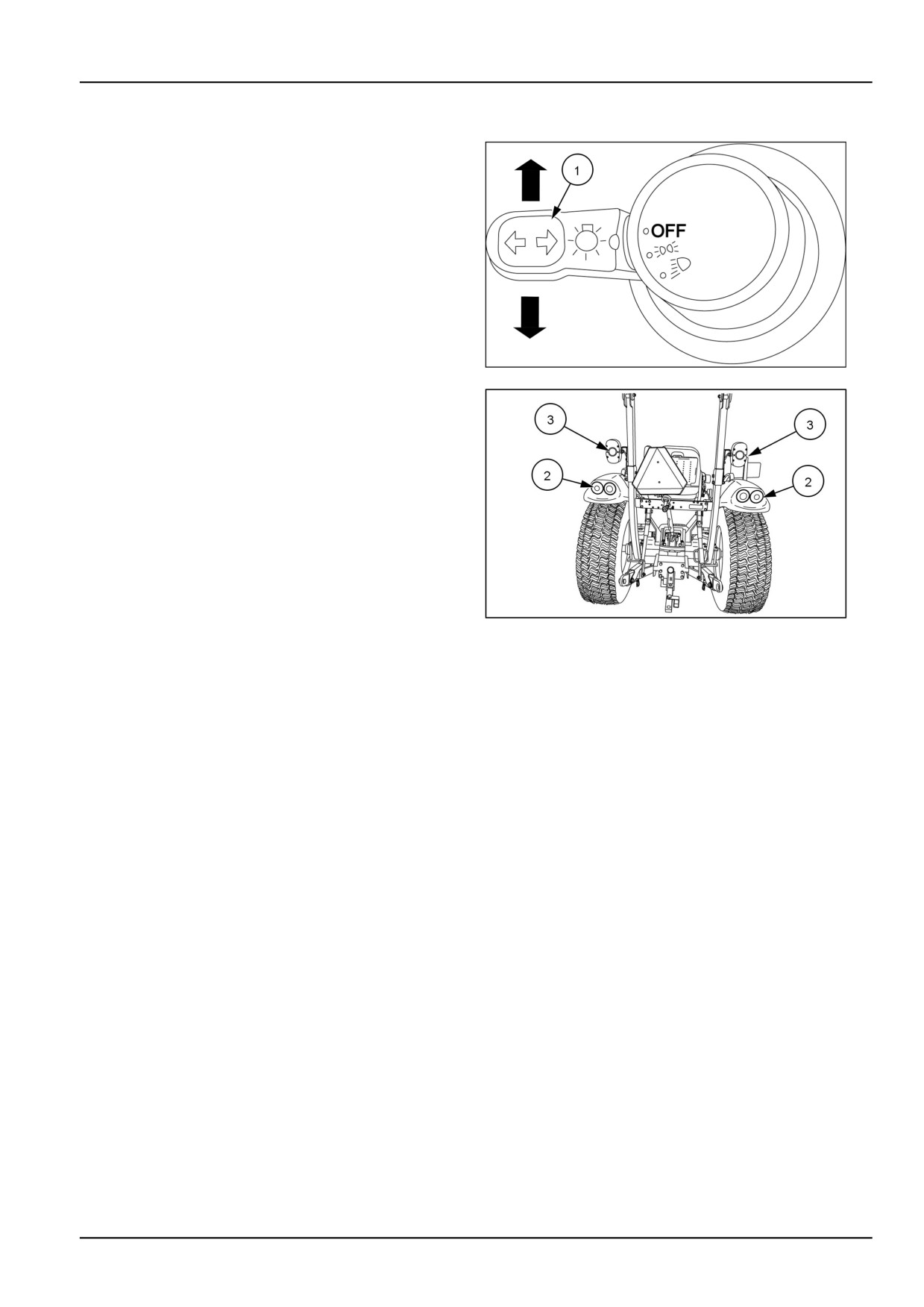
The multifunction switch is located on the left-hand side
of the dash panel.
1. The turn signal lights are activated by moving the mul-
tifunction switch lever (1) forward for right turns and
rearward for left turns.
2. The key switch has to be in the "ON" position for the
turn signal to operate.
3. When signaling a turn, the designated tail amber light
(2) and side hazard light (3) will flash and the tail amber
and side hazard lights for the opposite side of turning
direction will illuminate continuously.
NHIL13CT00525AA
1
NHIL13CT01013AA
2
5-3
5 - TRANSPORT OPERATIONS
Road lights operation
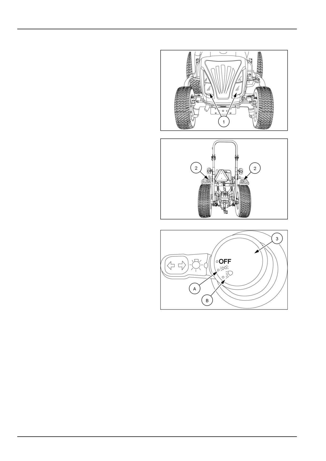
The road lights (1) and rear red taillights (2) are turned on
and off using the multifunction light switch located on the
left-hand side of the dash panel. The key switch must be
in the "ON" position for these lights to operate.
NHIL13CT01166AA
1
NHIL13CT01167AA
2
The multifunction light switch (3) is a rotary type switch
that has two positions (rotating clockwise from "OFF"
position), the two positions control the road lights and
taillights.
• First position, (A) illuminates the instrument panel and
taillights.
• Second position, (B) illuminates the instrument panel,
taillights and the road lights.
NOTE: For your protection, use the hazard warning lights,
road lights and SMV (slow moving vehicle) sign when trav-
eling on public roads, day or night.
NHIL13CT00525AA
3
5-4
5 - TRANSPORT OPERATIONS
Work lights operation
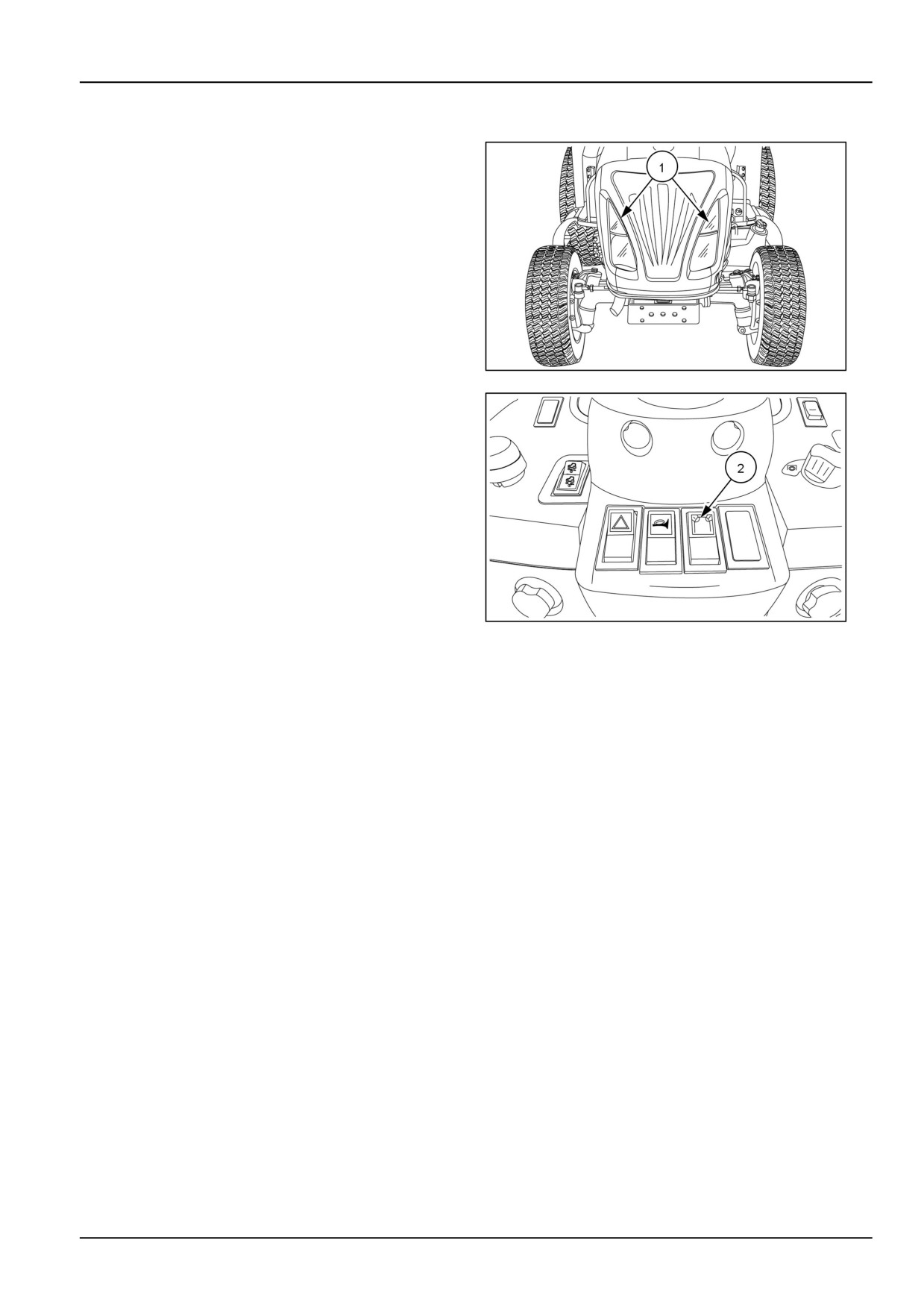
The work lights (1) are turned on and off using the work
light switch (2) located on the center of the console panel.
The key switch must be in the "ON" position for these
lights to operate.
Depress the top part of the work light switch to illuminate
the work lights.
NHIL13CT01166AA
1
NHIL13CT01004AA
2
5-5

5 - TRANSPORT OPERATIONS
Rear work light (optional)
The optional rear work light (1) is mounted to the Roll Over
Protection Structure - ROPS and is operated by a switch
located on the light. The work light can be mounted to the
ROPS, facing forward or rearward.
93110379
1
5-6
5 - TRANSPORT OPERATIONS
Driving the vehicle
Observe the following precautions when driving the
NOTE: Procure attaching hardware locally. Check im-
tractor:
plement assembly or the Operator's Manual for attach-
ing hardware specifications, such as bolt size and grade,
• Watch where you are going at all times, especially at
chain strength, washers, lock washers, nuts, etc.
row ends, on roads, and around trees.
• Use the hazard warning lights, road lights (low beam),
•
Engage the clutch slowly when driving out of a ditch,
and SMV (slow moving vehicle) sign when travelling on
gully, or up a steep hillside. Immediately disengage the
public roads, day or night.
clutch if the front wheels should rise off the ground.
• DO NOT permit anyone but the operator to ride on the
•
Reduce speed before turning quickly or applying
tractor.
brakes.
• Lock the brake pedals together when travelling on pub-
•
To make an emergency stop, depress both brake ped-
lic roads.
als and the clutch pedal (gear model only) simultane-
ously
• Make sure the PTO switch is in the "OFF" position.
NOTE: When making an emergency stop while oper-
• Keep the tractor in gear when going downhill. Use a
ating a HST model tractor depress both brake pedals
low gear to maintain control with minimum braking.
and release the forward or reverse HST pedal.
• If the tractor becomes stuck, back out to prevent upset-
•
Never apply the differential lock when turning.
ting the unit.
•
Use extreme caution and avoid hard applications of the
• Always use the drawbar for pull-type work. Do not pull
tractor brakes when pulling heavy, towed loads at road
from any other part of the tractor, since it may tip back-
speeds.
ward.
•
Any towed vehicle with a total weight exceeding that of
NOTICE: When transporting on the highway, a safety
the towing tractor should be equipped with brakes for
chain with tensile strength equal to the gross weight of
safe operation.
the implement should be connected between the tractor
and the towed implement. This will control the implement
•
Always sit in the driver's seat while starting or driving
in the event the hitch pin is lost. After attaching the safety
the tractor.
chain, check its adjustment by driving the tractor to the
•
Always check overhead clearance, especially when
right and to the left for a short distance. Readjust to
transporting the tractor.
tighten or loosen the chain as necessary. Safety chains
and suitable hardware are available from your NEW
HOLLAND Dealer.
5-7
5 - TRANSPORT OPERATIONS
SHIPPING TRANSPORT
Carrying the tractor on a transporter
NOTICE: Do not hook the chains around the steering
• Secure the front of the tractor at the front of the frame.
cylinders, tie rods or the axles. These components could
NOTE: Use suitable equipment or facilities when load-
be damaged by the chain or by excessive strain.
ing and unloading the tractor.
Transport the tractor with all four wheels on a flat bed
• Secure the rear of the tractor at the rear drawbar/hitch.
trailer or truck. Secure the tractor as follows:
RECOVERY TRANSPORT
Towing
Towing the tractor
from the front using the tow pin in the front weights or
front support. Have an operator steer and brake the trac-
WARNING
tor. If possible, run the engine to provide lubrication to the
Unexpected machine movement!
transmission and power steering.
Never attempt to start the machine by towing.
The machine could start unexpectedly.
Place the transmission gearshift levers in neutral, dis-
engaged the front wheel drive, differential lock and
Failure to comply could result in death or se-
rious injury.
park brake to tow the tractor. Do not exceed 20 km/h
W0941A
(12 mph).
NOTE: The tractor should only be towed a short distance,
WARNING
such as out of a building. Do not tow on roadways or as
Transport hazard!
a method of transport.
Do not tow the machine on public roads. Tow-
ing could cause a safety hazard for other ve-
Towing implements
hicles using the roadway.
Failure to comply could result in death or se-
WARNING
rious injury.
Loss of control hazard!
W1012A
Always attach or pull towed vehicles from the
tractor drawbar.
WARNING
Failure to comply could result in death or se-
Hazard to bystanders!
rious injury.
W1013A
Do not use cables or rope to tow the machine.
If the cable or rope breaks or slips, it may whip
For towed vehicles without brake system:
back with enough force to cause serious in-
jury. When using a chain, attach the chain with
• Do not exceed transport speed of 32 km/h (20 mph).
the hook's open side facing UP. If the hook
• Do not exceed fully loaded mass (weight) of 1.5 times
slips, it will drop down instead of flying up.
the mass (weight) of the towing unit.
Failure to comply could result in death or se-
rious injury.
W0441A
For towed vehicles with brake system:
• Do not exceed transport speed of 32 km/h (20 mph).
NOTICE: If it is necessary to tow the tractor, all gear
• Do not exceed fully loaded mass (weight) of 4.5 times
levers must be moved to the neutral position before stop-
the mass (weight) of the towing unit.
ping the engine otherwise damage to transmission com-
ponents may occur during towing.
Use a strong chain when towing the tractor. Tow the trac-
tor from the rear using only the drawbar. Tow the tractor
5-8
6 - WORKING OPERATIONS
6 - WORKING OPERATIONS###_6_###
GENERAL INFORMATION
Tractor ballasting
For sufficient traction and maximum performance
When a rear mounted implement is raised to the transport
in heavy draft operations, and to counterbalance
position, the front wheel reaction should be at least 20%
rear-mounted equipment, weight should be added to the
of tractor weight.
tractor in the form of liquid ballast, cast iron weights,
or a combination of both. Only enough weight should
Add additional front end ballast as required for stability
be added to provide good traction and stability. Adding
during operation and transport. Tractor front end ballast
more weight than is needed results in unnecessary soil
may not always maintain satisfactory stability if the tractor
compaction, increased rolling resistance, and higher fuel
is operated at high speed on rough terrain. Reduce tractor
consumption.
speed and exercise caution under these conditions.
NOTE: When adding weight to the tractor, tire pressures
When using front-mounted equipment, add weight to the
may need to be increased. See Wheels - Tire pressure
rear axle to maintain good traction and stability. Front-
in this manual.
mounted equipment varies in weight. Refer to equipment
manual for ballasting.
Front end ballast may be required for stability and steering
control when weight is transferred from the front wheels
WEIGHTING LIMITATIONS
to the rear wheels as an implement is raised by the tractor
three-point hitch.
The weighting limitations that follow are limitations only.
They do not imply that the tractor should be weighted to
As a general guide:
attain the weights given. Use only enough weight to ob-
tain good performance.
Ballast the tractor (less implement) so that approximately
one-third of the tractor weight is on the front wheels. For
optimum traction, tractors equipped with front-wheel drive
should be ballasted so that 40 - 45 % of machine weight
is on the front wheels.
6-1
6 - WORKING OPERATIONS
Tractor ballasting weights
Cast iron weights (Optional)
Cast iron weights are available as accessories from your
NEW HOLLAND Dealer. Weights can be mounted on the
front end of the tractor, rear of the tractor and on the rear
wheels.
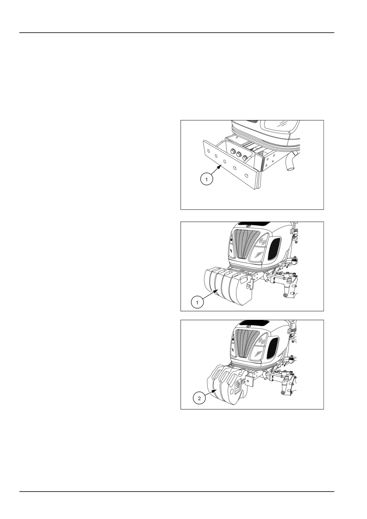
Front weight carrier bracket (Optional)
To mount cast iron weights on the front of the tractor an op-
tional extension mounting bracket (1) must be installed on
the front of the tractor frame. When the extension bracket
is installed, a maximum of five front weights can be in-
stalled.
93100896
1
Weight options:
A maximum of five 27 kg (60 lb) weights (1) for a total
weight of 136 kg (300 lb) .
A maximum of three 45 kg (100 lb) weights (2) for a total
weight of 135 kg (300 lb) .
NOTE: The front extension mounting bracket with a maxi-
mum of three 27 kg (60 lb) weights attached is compatible
with a grille guard.
NOTE: The front extension mounting bracket with 45 kg
(100 lb) weights is not compatible with a grille guard.
93100898
2
NOTE: The front extension mounting bracket is not com-
patible with a loader installed.
93100897
3
Rear wheel weights (Optional)
Rear wheel weights are not available only for the Boomer
33/37 model tractors.
6-2
6 - WORKING OPERATIONS
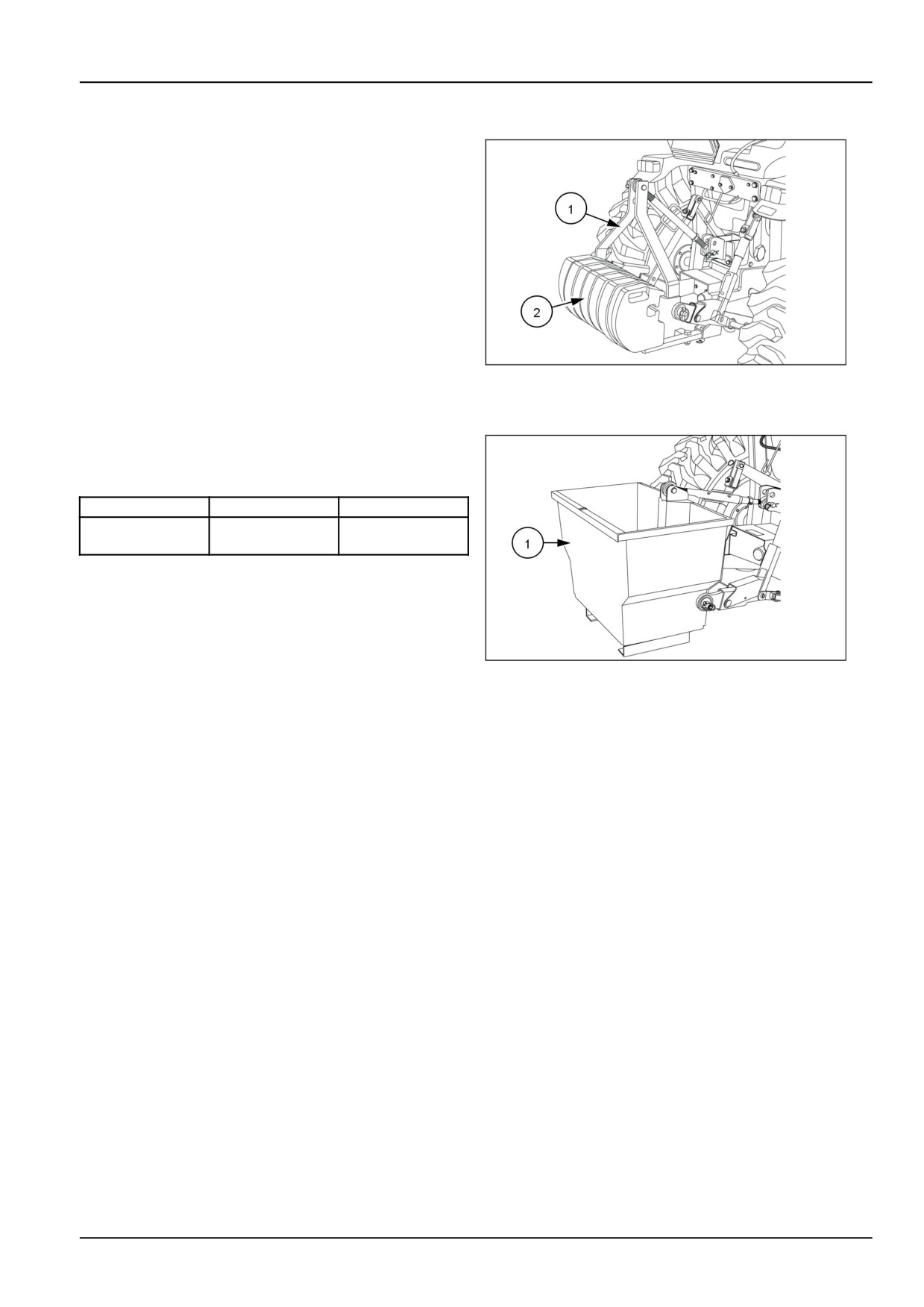
Rear counter weight bracket (Optional)
To mount cast iron weights on the rear of the tractor an
optional weight bracket (1) must be installed on the rear
3-point hitch. A maximum of seven suitcase weights (2)
can be fitted to the bracket.
Weight options:
A maximum of seven 27 kg (60 lb) weights for a total
weight of 191 kg (421 lb).
A maximum of two 27 kg (60 lb) weights, and five 45 kg
(100 lb) weights, for a total weight of 282 kg (622 lb).
93100917
4
Ballasting box (Optional)
A category-1, 3-point hitch, 227 kg (500 lb) capacity bal-
lasting box (1) may be purchased as extra equipment.
Load with sand, gravel, or similar loose ballast as needed.
Weight (Empty)
Weight (Loaded)
3-Point Hitch
46 kg (101 lb)
228 kg (503 lb)
Ballasting Box
93100918
5
6-3
6 - WORKING OPERATIONS
Liquid ballast
It is a common practice to add weight to the tractor by
Ballast Weights (Per Tire) 600 g/5 lb Gal Solution/CaCl2.
filling the rear tires with liquid. A calcium chloride (CaCl2)
Tire Type
Approximate
and water solution is recommended due to its low freezing
Tire Size
Added Weight
point and greater density (weight per gallon) than pure
water.
Agricultural
13.6-24, 4PR, R1
182 kg (400 lb)
Turf
41 x 14.00-20,
157 kg (346 lb)
Never exceed the total recommended weight for the trac-
4PR, R3
tor. Because special equipment is required to fill the tires,
consult your NEW HOLLAND Dealer.
Industrial (R4)
17.5L x 24, 6PR,
272 kg (600
lb)
R4
Tires should never be filled beyond 75 %. At 75 % full, the
liquid will come to the valve stem when the valve stem is
at its highest point at the top of the wheel.
6-4
7 - MAINTENANCE
7 - MAINTENANCE###_7_###
GENERAL INFORMATION
General information
Adequate lubrication and maintenance on a regular
tration of engine and hydraulic systems. See your NEW
schedule is vital to maintaining your equipment. To
HOLLAND dealer for additional oil quantities.
ensure long service and efficient operation, follow the
lubrication and maintenance schedules outlined in this
Regular lubrication is the best insurance against delays
manual. The use of proper fuels, oils, grease and filters,
and repairs. Proper lubrication will extend machine life.
as well as keeping the systems clean, will also extend
Refer to the following charts for lubricants and service
machine and component life.
intervals.
NOTICE: While any company can perform necessary
NOTICE: Failure to complete the required maintenance
maintenance or repairs on your equipment, NEW HOL-
at the recommended intervals can cause unnecessary
LAND strongly recommends that you use only authorized
downtime.
NEW HOLLAND dealers and products that meet the
The intervals listed in the Lubrication Chart are guidelines
given specifications. Improperly or incorrectly performed
maintenance and repair voids the equipment warranty
to be used when operating in normal conditions. Adjust
and may affect service intervals.
the intervals for operating in adverse environmental and
working conditions. The intervals should be shortened for
NOTICE: Always use genuine NEW HOLLAND replace-
sandy, dusty and extremely hot operating conditions.
ment parts, oils and filters to ensure proper operation, fil-
WARNING
Avoid injury!
1. Disengage all drives.
2. Engage parking brake.
3. Lower all attachments to the ground, or
raise and engage all safety locks.
4. Shut off engine.
5. Remove key from key switch.
6. Wait for all machine movement to stop.
Failure to comply could result in death or se-
rious injury.
W1197A
WARNING
Entanglement hazard!
Disengage the Power Take-Off (PTO), turn off
the engine, and remove the key. Wait for all
movement to stop before leaving the opera-
tor's position. Never adjust, lubricate, clean,
or unplug machine with the engine running.
Failure to comply could result in death or se-
rious injury.
W0227A
WARNING
Illustrations in this manual may show protec-
tive shielding open or removed to better illus-
trate a particular feature or adjustment.
Replace all shields before operating the ma-
chine.
Failure to comply could result in death or se-
rious injury.
W0012A
Always clean the area around dipsticks, fill caps, and
Drain, flush and refill the system any time you suspect it
check plugs when checking fluid levels. Failure to clean
is contaminated.
these areas may allow contamination to enter the system.
7-1
7 - MAINTENANCE
Grease Fittings
Wipe dirt from fittings before greasing.
Pump fresh grease into fitting to adequately lubricate the
component and force out any contamination from the
grease passage.
Wipe off excess grease.
Use a grease gun containing clean high grade of NEW
HOLLAND AMBRA GR-9 MULTI-PURPOSE GREASE.
7-2
7 - MAINTENANCE
Safety rules diesel fuel
• Use clean, quality No.
1-D or No.
2-D fuel (ASTM
Fuel Usage Safety
D975).
•
UNDER NO CIRCUMSTANCES should gasoline, alco-
• Use No. 1-D fuel if the ambient temperature is expected
hol, or gasohol be added to diesel fuel. These combina-
to be lower than 4 °C (39 °F) or if the tractor is to be
tions can create an increased fire or explosive hazard.
used at an altitude exceeding 1524 m (5000 ft).
•
Never remove the fuel cap or refuel the tractor while the
• Use No.
1-2 diesel fuel with a pour point of at least
engine is running or hot.
-12 °C (10 °F) below the expected ambient temperature
to prevent fuel flow problems in cold weather.
• Never smoke while refueling or anywhere near fuel.
• Keep dirt from entering the fuel tank.
• When filling the tank, maintain control of the nozzle.
• Sulfur content of the fuel should be no more than 0.5 %.
• Do not fill the fuel tank to capacity. Allow room for ex-
pansion.
• Sediment and water content should not exceed 0.5 %.
•
Wipe up spills immediately.
• Minimum cetane number is 40. Low temperature or
high altitude operation may require use of fuel with a
• Always tighten the fuel cap securely.
higher cetane number.
• If the original fuel tank cap is lost, always replace it with
a New Holland approved cap. A "will-fit" cap may not
• Use properly mixed winter fuel when temperatures are
extremely cold. In most areas, diesel fuel is properly
be safe.
blended for summer and winter grades as ambient tem-
• Keep equipment properly maintained.
peratures change. In winter, use winter grade diesel
fuel only. Otherwise, the fuel may cloud and block the
• Do not drive equipment near open fires.
fuel system.
• Never use gasoline for cleaning parts.
Biodiesel fuel
The use of biodiesel blends meeting Specification Stan-
Biodiesel fuel has a higher cloud point than conventional
dards ASTM 6751 or EN14214 are approved for your en-
diesel fuels and is not recommended in winter months.
gine up to B5 ( 5 % blend ratio). It is highly recommended
Consult your fuel dealer for winter fuel requirements for
to use biodiesel fuel from accredited suppliers to maintain
your area.
quality and consistency of the fuel.
Biodiesel fuel attracts moisture and may contain a higher
Biodiesel does not have a long term stability and should
content of water. It may be necessary to drain the fuel
not be left in engines or stored for more than four months.
filter water trap more frequently.
If your machine is stored for long term, engine should be
flushed, prior to storage, by running for a minimum of 30
minutes with conventional diesel fuel.
7-3
7 - MAINTENANCE
Refueling the tractor
WARNING
Fire hazard!
When handling diesel fuel, observe the follow-
ing precautions:
1. Do not smoke.
2. Never fill the tank when the engine is run-
ning.
3. Wipe up spilled fuel immediately.
Failure to comply could result in death or se-
rious injury.
W0099A
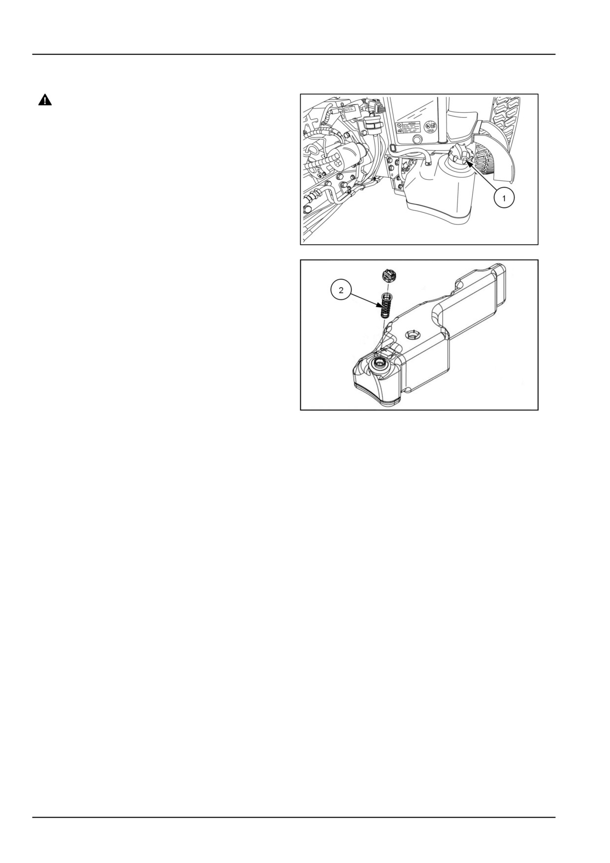
The fuel tank filler cap (1) is located at the front left-hand
side of the operator’s platform of the tractor.
NHIL13CT01024AA
1
NOTICE: Before removing the cap, wipe all dust and dirt
from around the cap to prevent debris from falling into the
tank while filling.
There is a strainer (2) located inside the fuel tank neck.
Clean strainer periodically. Only dispense fuel into the
tank with the strainer installed.
Use an approved fuel container and check the inside of
the container periodically for cleanliness. Fuel tank ca-
pacity is 40.0 l (10.5 US gal).
NOTE: The fuel cap is a vented-type. Use only an ap-
proved NEW HOLLAND replacement cap to prevent fuel
NHIL13CT01254AA
2
system-related problems.
If there is no filter on the storage tank or fuel container,
filter the fuel through a 100-mesh or finer screen when fill-
ing the tractor fuel tank. Keep the tractor tank as full as
possible (without filling to capacity) to minimize conden-
sation.
NOTE: It is a good practice to fill the fuel tank at the end
of each day, as this will reduce overnight condensation.
7-4
7 - MAINTENANCE
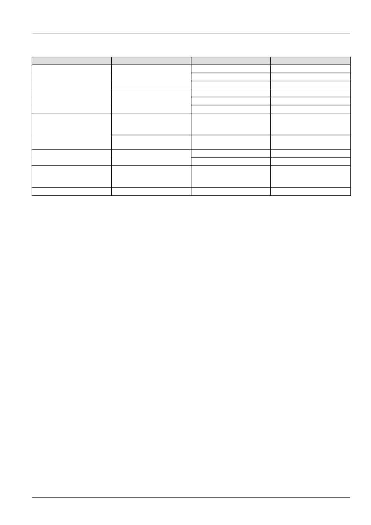
Consumables
Lubricant
Type and Description
Part Number
Container Size
NEW HOLLAND AMBRA
9613313
0.946 l (1 US qt)
MASTERGOLD™ ENGINE OIL
86641052
3.785 l (1 US gal)
Engine Oil
SAE 10W-30 CJ-4
9673508
18.93 l (5 US gal)
API CJ-4
NEW HOLLAND AMBRA
86641081
0.946 l (1 US qt)
MASTERGOLD™ ENGINE OIL
86641082
3.785 l (1 US gal)
SAE 15W-40 CJ-4
86641083
18.93 l (5 US gal)
NEW HOLLAND AMBRA
MULTI G 134™ HYDRAULIC
9624451
18.93 l (5 US gal)
Transmission/Hydraulic Oil
TRANSMISSION OIL
TUTELA F200A
B17805
18.93 l (5 US gal)
MULTI-SEASON
NEW HOLLAND AMBRA
B80901
0.946 l (1 US qt)
Front Axle/Gear Oil
HYPOIDE 90
B80903
9.46 l (2.5 US gal)
NEW HOLLAND AMBRA
Grease
GR-9 MULTI-PURPOSE
73340211
Tube 14 oz
GREASE
Coolant
Ethylene Glycol Coolant
NA
NA
7-5
7 - MAINTENANCE
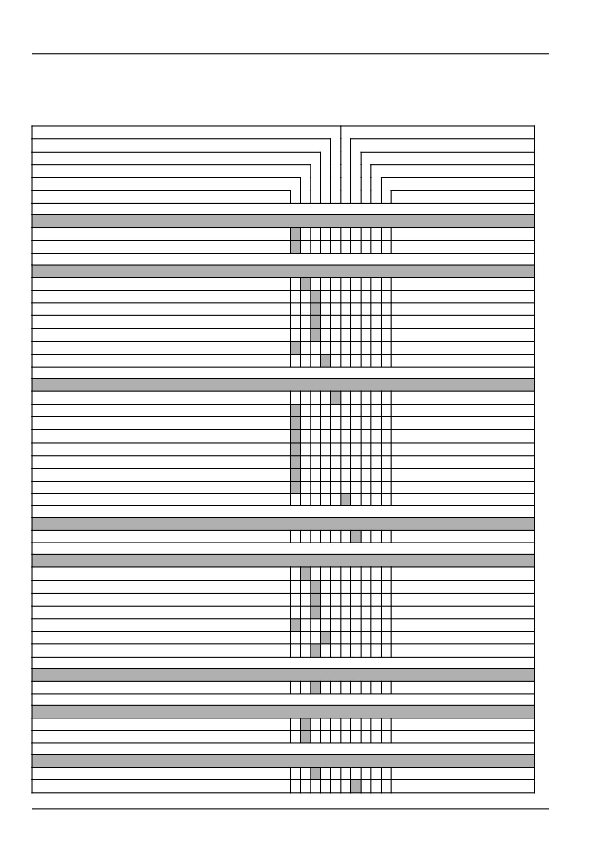
MAINTENANCE CHART
Maintenance Chart
Grease
Cleaning
Tighten
Drain fluid
Replace
Bleed
Change fluid
Adjust
Check
Test
Maintenance action
Page no.
Every 10 hours or daily
Engine oil level
7-7
Engine cooling system
7-9
After first 50 hours
Engine oil and filter
7-10
Pre-fuel filter
7-12
Fuel filter
7-13
Hydraulic oil filter
7-14
Hydrostatic (HST) oil filter
7-15
Roll Over Protective Structure (ROPS)
7-16
Wheels bolt/nut
7-17
Every 50 hours
Grease fittings
7-18
Transmission fluid level
7-19
Clutch pedal free play
7-19
Brake pedal free play
7-20
Hydrostatic transmission (HST) neutral adjustment
7-20
Engine belts
7-21
Tires and wheels
7-22
Front axle differential oil level
7-23
Air cleaner
7-24
Every
100
hours
Fuel filter
7-25
Every
300
hours
Engine oil and filter
7-26
Hydraulic filter
7-26
Hydrostatic (HST) oil filter
7-26
Pre-fuel filter
7-26
Engine belts
7-26
Wheels bolt/nut
7-26
Air cleaner primary element
7-27
Every
500
hours
Fuel filter
7-28
Every
600
hours
Front axle differential fluid
7-29
Transmission fluid
7-30
Every 1000 hours
Air cleaner inner element
7-31
Engine coolant
7-32
7-6
7 - MAINTENANCE
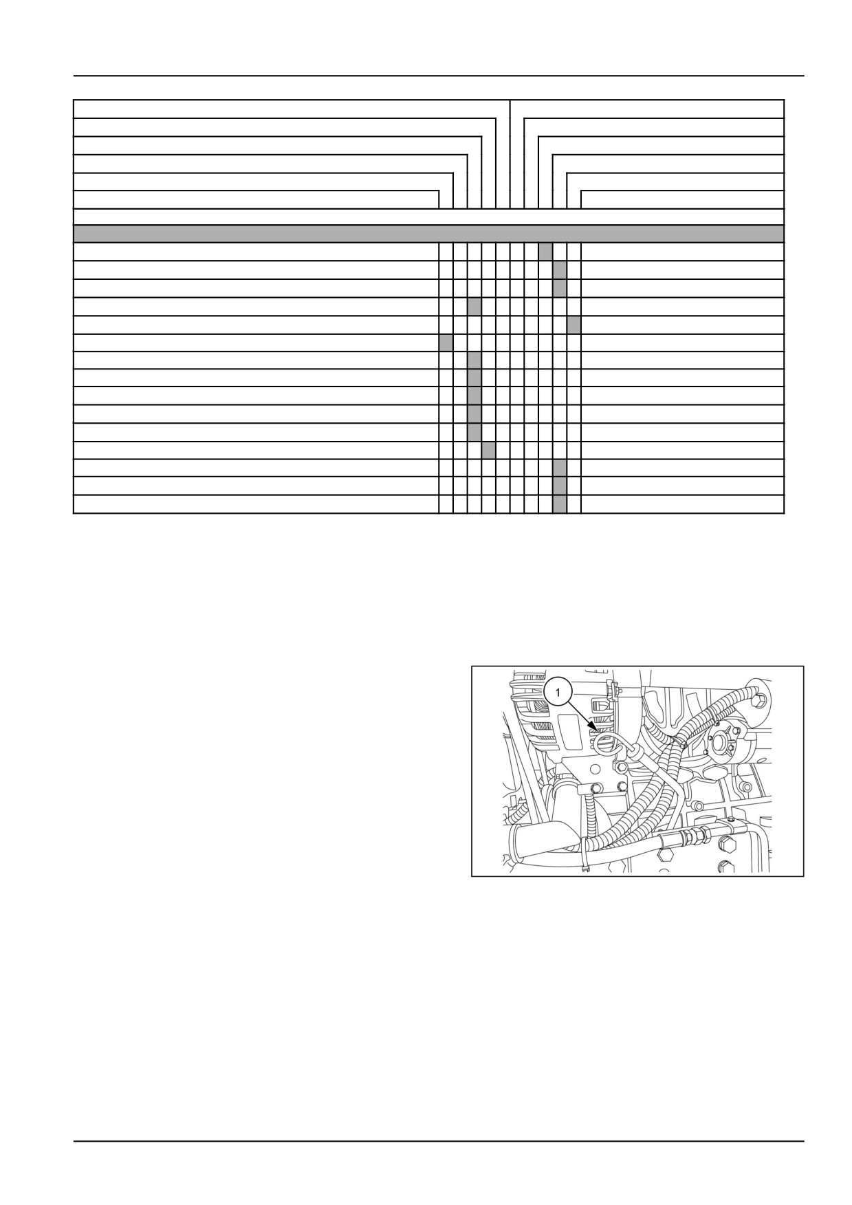
Grease
Cleaning
Tighten
Drain fluid
Replace
Bleed
Change fluid
Adjust
Check
Test
Maintenance action
Page no.
General maintenance
Fuel injection system
7-33
Hydrostatic transmission (HST) neutral adjustment
7-35
Engine belts
7-36
Roll Over Protective Structure (ROPS) frame
7-37
Battery
7-37
Alternator
7-38
Fuses
7-39
Maxi-fuse
7-40
Headlight bulb
7-40
Tail/brake light bulb
7-41
Turn signal/hazard light bulb
7-41
Wheels bolt/nut
7-43
Front wheels toe-in
7-43
Brake pedal free play
7-44
Clutch pedal free play
7-45
Every 10 hours or daily
Engine oil level
NOTE: Check the engine oil level daily or after every 10
hours of operation.
1. After the engine has been stopped for a period of time
and with the tractor standing level, check the oil level
using the dipstick (1).
NHIL13CT01134AA
1
7-7
7 - MAINTENANCE
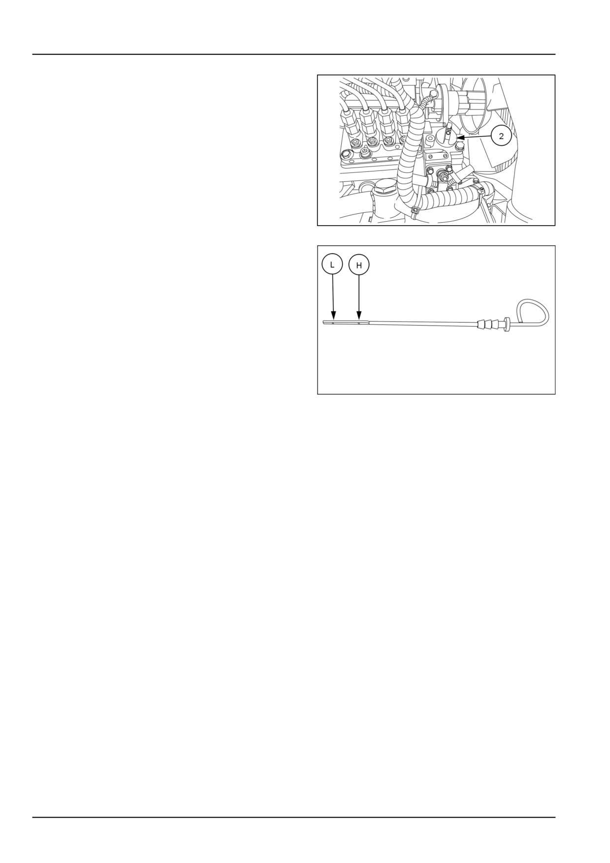
2. If the oil level is low, remove the filler cap (2) add oil
through the filler hole.
NHIL13CT01118AA
2
3. Add enough oil so that the level registers between the
(L) low and the (H) high marks on the dipstick. Do not
overfill.
93100903
3
7-8
7 - MAINTENANCE
Engine cooling system
Cooling system
The tractor engine must operate at the correct temperature
to obtain maximum efficiency and service life. This is de-
pendent on the cooling system.
Always fill the system with a 50/50 solution of ethylene gly-
col antifreeze and water.
Checking the coolant level
WARNING
Burn hazard!
Hot coolant can spray and scald if you remove the radiator or deaeration tank cap while the system
is hot. To remove the cap: allow the system to cool, turn the cap to the first notch, and wait for all
pressure to release. Remove the cap only after all pressure has released.
Failure to comply could result in death or serious injury.
W0367A
NOTE: Check the coolant level daily or after every 10 hours
of operation. The engine should be cold when coolant level
is checked.
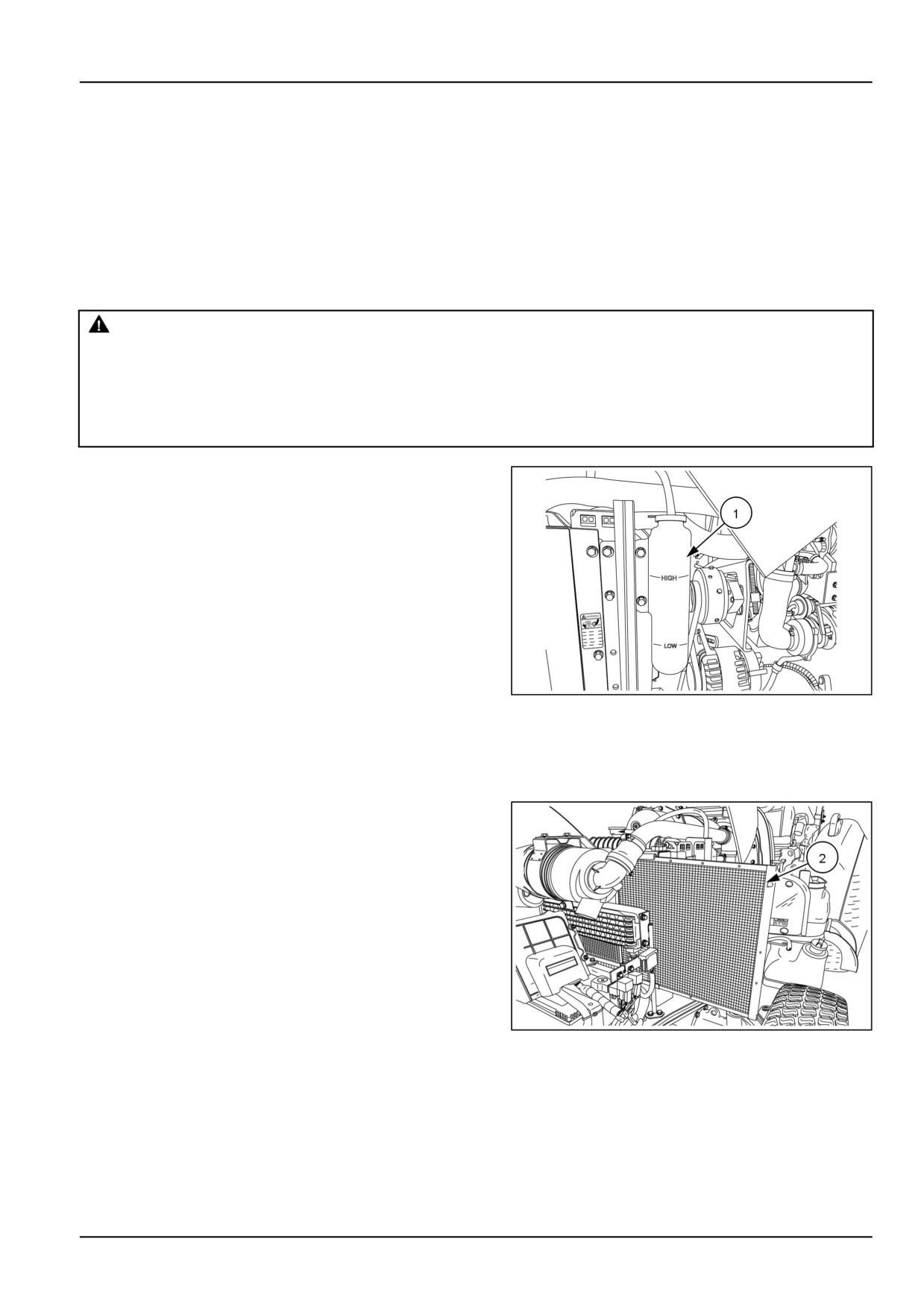
1. Visually inspect the coolant level in the coolant recov-
ery reservoir (1) the coolant level should be between
the "LOW" and "HIGH" lines located on the side of the
reservoir.
2. If the coolant level is not between the "LOW" and
"HIGH" lines, add a water/antifreeze solution as neces-
sary. The cooling system already contains antifreeze,
add only antifreeze solution of the correct water/an-
NHIL13CT01235AA
1
tifreeze mixture. Pure water will dilute the solution and
weaken its protection.
3. Keep the radiator fins clear of chaff or dirt to allow free
air movement.
4. Check and clean front radiator screen (2) every 10
hours of operation.
NHIL13CT00994AA
2
7-9
7 - MAINTENANCE
After first 50 hours
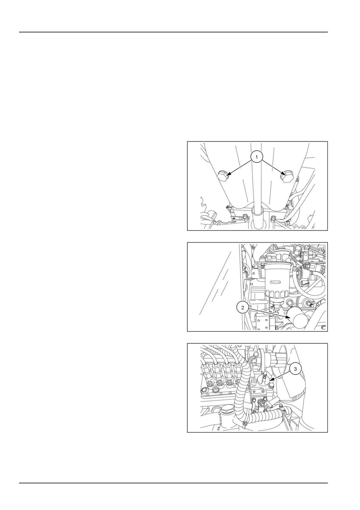
Engine oil and filter
NOTE: Change the engine oil and filter after the first 50 hours of operation, then every 300 hours thereafter. If the
tractor is operated for extended periods of time at maximum rated power and speed, or under other types of continu-
ous, severe operating conditions, the engine oil and filter should be changed at 200 hour intervals following the initial
oil change.
To change the engine oil:
1. Place a suitable container beneath the drain opening
to catch the used oil. With the tractor engine off but
at normal operating temperature, remove the two drain
plugs, (1). located on both sides of the engine oil pan.
Reinstall the plugs after all of the oil has been drained.
NHIL13CT01142AA
1
2. Next, place a container below the oil filter, (2), to catch
the used oil and unscrew the oil filter. Discard the used
oil and filter.
3. Coat the gasket on the new filter with a film of clean oil.
Screw the filter into place until the gasket contacts its
mating surface, then turn the filter approximately three-
quarters of a turn by hand. Do not overtighten.
NHIL13CT01068AA
2
4. Add the proper type and level of new oil at fill port (3) ,
then start the engine and check the filter for leaks.
NOTE: Oil Capacity, with filter 5.7 l (6.0 US qt)
NOTICE: Use of any engine oil other than (CJ-4) may clog
the (DPF) earlier than expected and fuel usage may in-
crease.
NHIL13CT01118AA
3
7-10

7 - MAINTENANCE
Recommended Oils
Ambient Temp (°F)
Recommended Oil
-23.3 - 49 °C (-10 - 120 °F)
NEW HOLLAND AMBRA MASTERGOLD™ HSP ENGINE
OIL SAE 10W-30
-12 - 49 °C (10 - 120 °F)
NEW HOLLAND AMBRA MASTERGOLD™ HSP ENGINE
OIL SAE 15W-40
Oil Specification API CJ-4
7-11
7 - MAINTENANCE
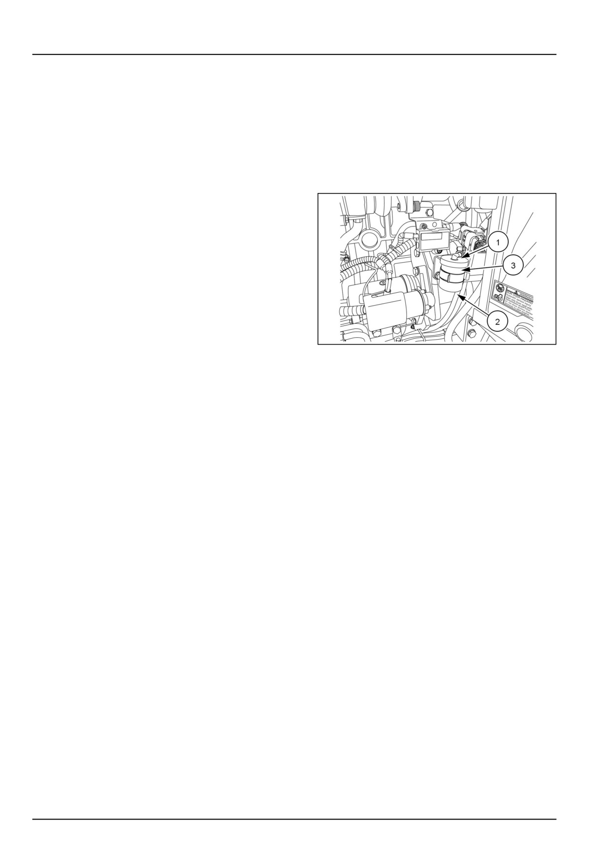
Pre-fuel filter
NOTE: Change the pre-fuel filter after the first 50 hours of
operation, then following every 300 operating hours there-
after.
NOTICE: In extreme dusty/dirty environments, it is rec-
ommended to visually inspect the pre-fuel filter every 100
hours of operation for contamination and replacement at
every 200 hours.
1. Close off the fuel inlet hose (1) and outlet hose (2) at
the fuel filter.
2. Remove the pre-fuel filter (3) from the retaining clip.
3. Install new fuel filter into retaining clip. .
4. Reinstall inlet and outlet hoses onto the filter.
5. To bleed the fuel system and injection pump see Fuel
injection system - Bleed
NHIL13CT01161AA
1
NOTE: There is not a fuel shutoff valve in the fuel system. To stop the fuel flow from the fuel tank, the fuel inlet hose
to the fuel filter has to be removed from the fuel filter base and a plug installed or the fuel hose needs to be crimped
shut to shutoff the fuel flow.
7-12
7 - MAINTENANCE
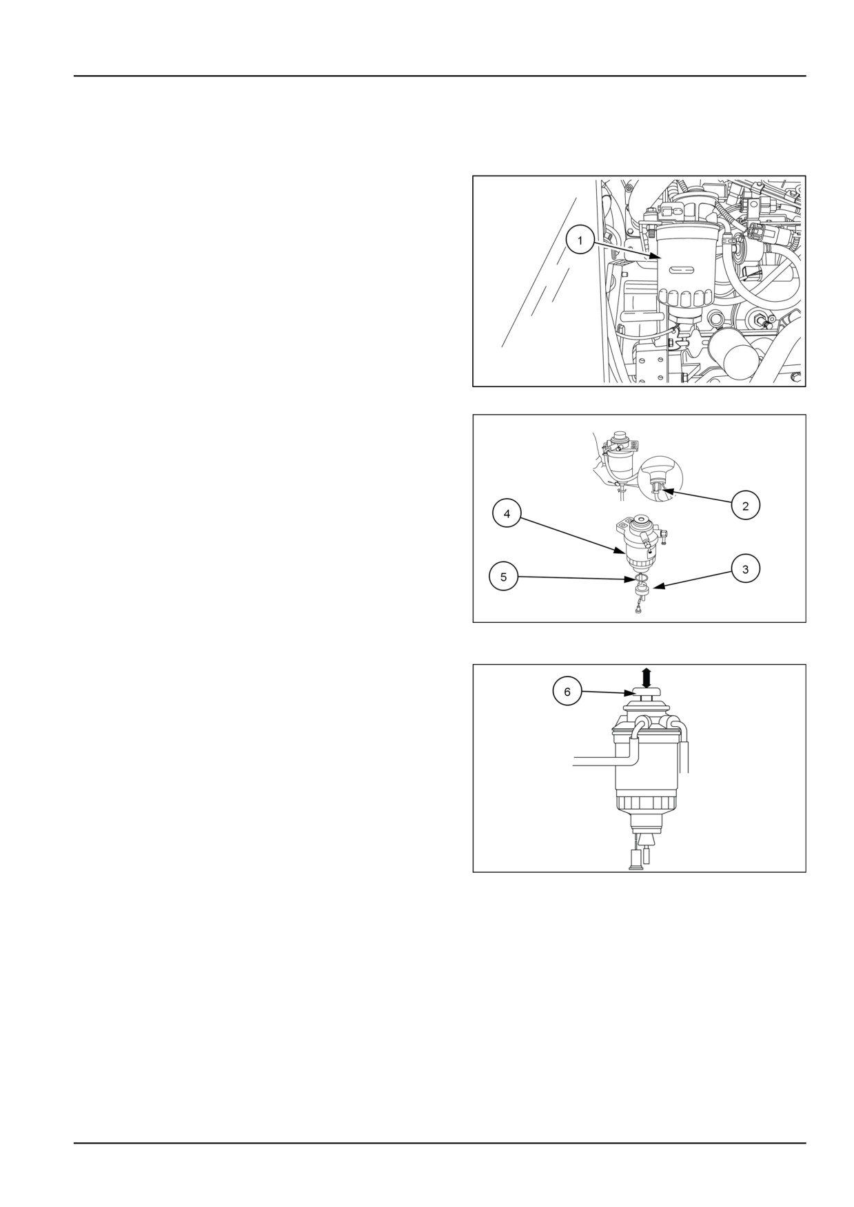
Fuel filter
NOTE: Change the diesel fuel filter (1) after the first 50 hours of operation, then following every 500 operating hours
thereafter.
NHIL13CT01068AA
1
1. Loosen fuel filter drain plug (2) and drain fuel from the
filter.
2. Disconnect the electrical connector from the fuel filter
sensor (3).
3. Remove the fuel filter element (4) from the filter base
4. Remove the fuel filter sensor (3) from the original ele-
ment and install sensor with O-ring (5) onto new ele-
ment.
5. Install new element onto the filter base.
6. Connect electrical connector to the fuel filter sensor.
93100920
2
7. Tighten fuel filter drain plug.
8. Bleed the air from the fuel filter, by pressing the manual
fuel feed pump (6) several times. The manual feed
pump will bleed the air back to the fuel tank. There
is no need to open any bleed ports in the fuel system.
NHIL13CT01251AA
3
7-13
7 - MAINTENANCE
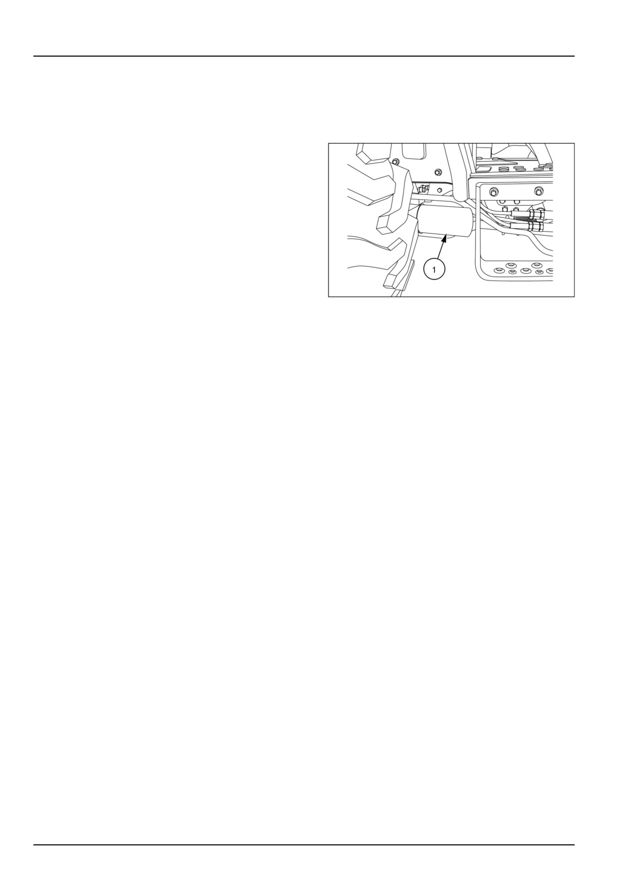
Hydraulic oil filter - Hydraulic system
NOTE: Replace the hydraulic system oil filter after the first
50 hours of operation, and then following every 300 hours
of operation thereafter.
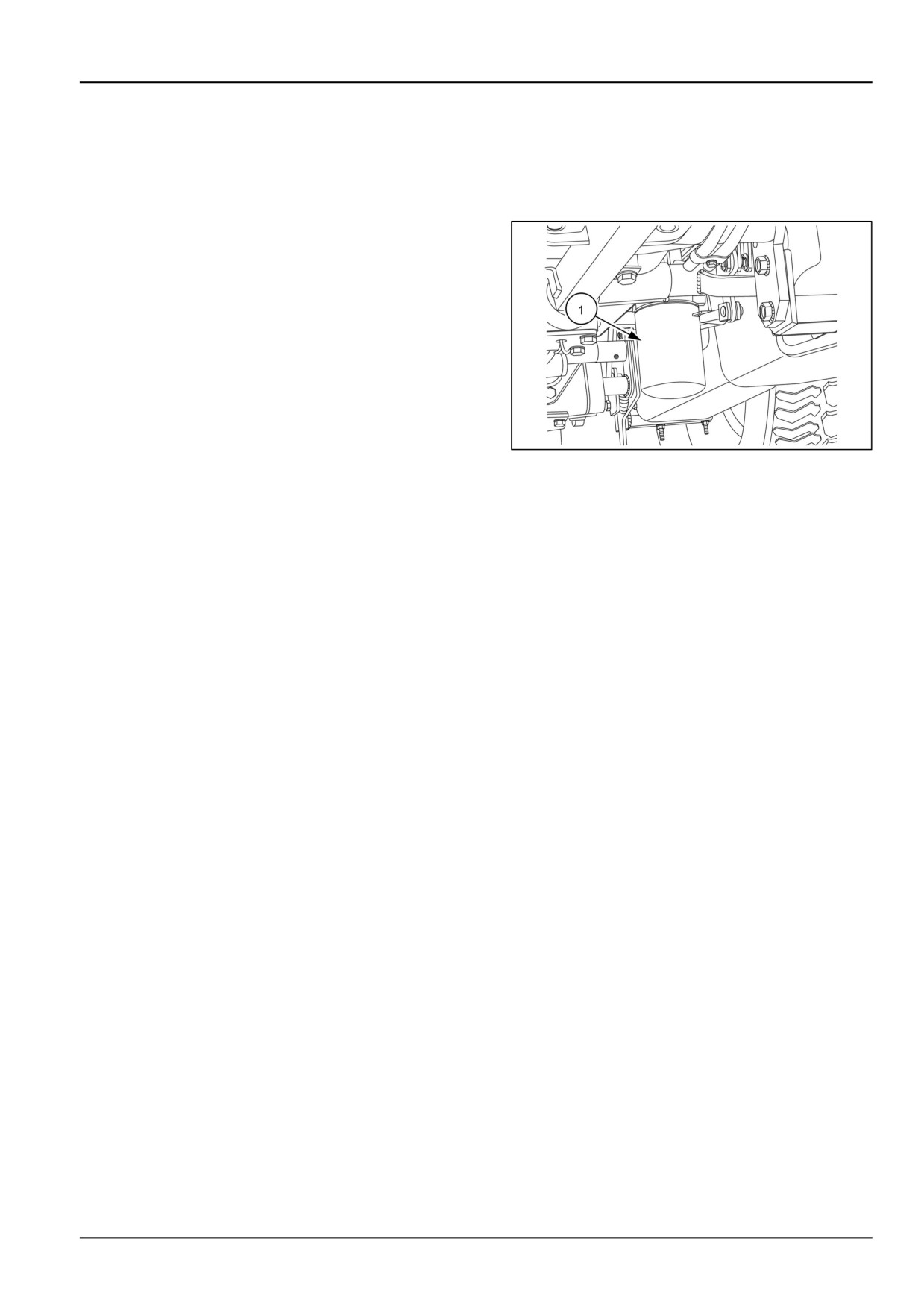
The hydraulic system uses a spin-on type oil filter (1), lo-
cated on the right-hand side of the tractor underneath the
operator's platform. To replace the filter :
1. Unscrew the used oil filter and discard.
2. Coat the gasket on the new filter with a film of clean oil.
Screw the filter into place until the gasket contacts the
sealing surface, then tighten the filter by hand approxi-
mately three-quarters of a turn. Do not overtighten.
3. Start the engine and check the filter for leaks.
4. Stop the engine and check the hydraulic system oil
level. Add oil if necessary.
93100934
1
7-14
7 - MAINTENANCE
Hydrostatic (HST) oil filter
NOTE: Change the hydrostatic (HST) system oil filter after the first 50 hours of operation, and then following every
300 hours of operation thereafter.
The hydrostatic system uses a spin-on type oil filter (1),
located on the left-hand side of the tractor underneath the
operator's platform.
NHIL13CT01245AA
1
To replace the filter:
1. Unscrew the used oil filter and discard.
2. Coat the gasket on the new filter with a film of clean oil.
Screw the filter into place until the gasket contacts the
sealing surface, then tighten the filter by hand approxi-
mately three-quarters of a turn. Do not overtighten.
3. Start the engine and check the filter for leaks.
4. Stop the engine and check the hydraulic system oil
level. Add oil if necessary.
7-15
7 - MAINTENANCE
Roll Over Protective Structure (ROPS)
NOTE: Inspect the ROPS after the first 50 hours of opera-
tion. Following the initial inspection, the ROPS should be
checked after every 300 hours of operation or every six
months, whichever comes first.
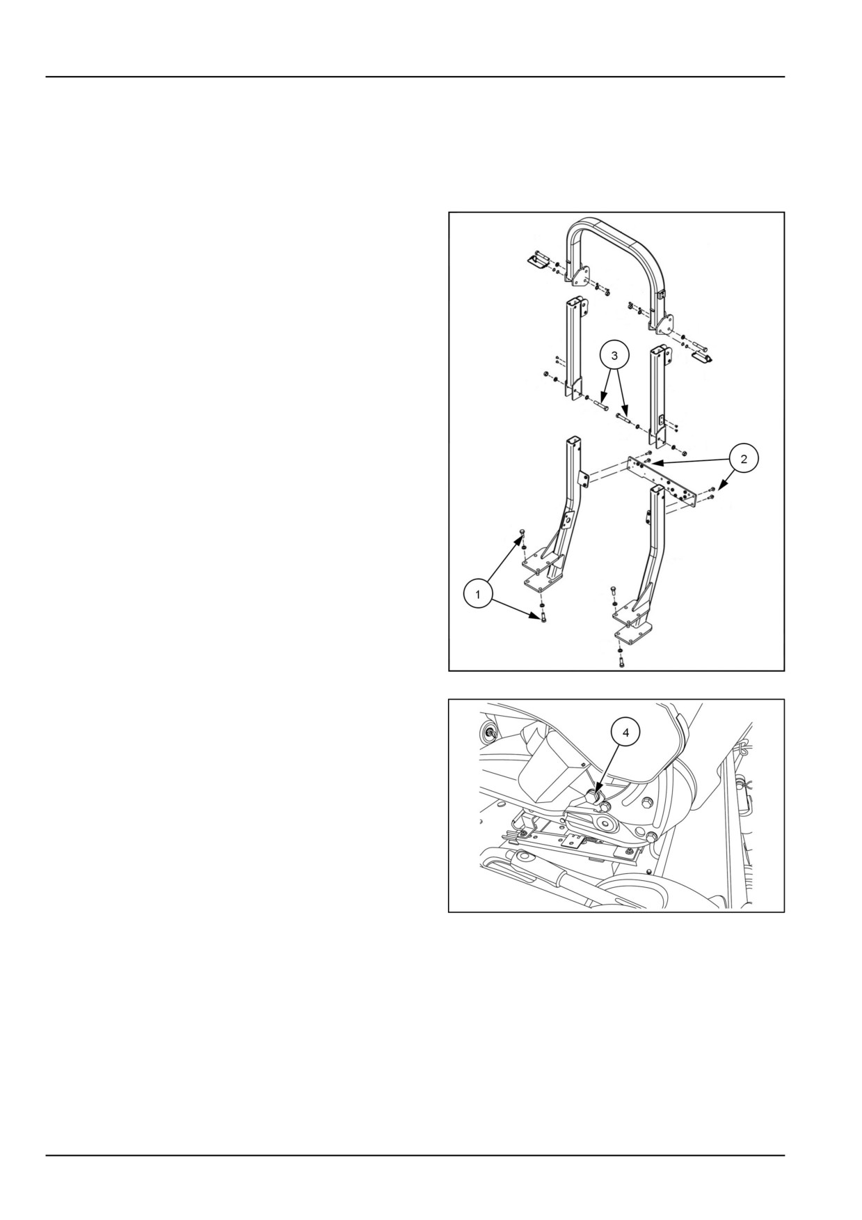
1. Check the torque of the ROPS bottom portion mounting
bolts, (1). Tighten the M14 bolts to the correct torque
of 147 N·m (108 lb ft) if necessary.
2. Check the torque of the ROPS cross brace mounting
bolts (2). Tighten the M10 bolts to the correct torque of
60 N·m (41 lb ft) if necessary.
3. Check the torque of the ROPS mid portion mounting
bolts (3). Tighten the M14 bolts to the correct torque of
147 N·m (108 lb ft) if necessary.
NHIL13CT01280BA
1
4. Inspect the operator's seat and the mounting parts for
the seat belt. Tighten theM10 bolts (4) to the correct
torque of 54 N·m (40 lb ft) if necessary and replace any
parts that show wear or damage.
NHIL13CT01162AA
2
7-16
7 - MAINTENANCE
Wheels bolt/nut
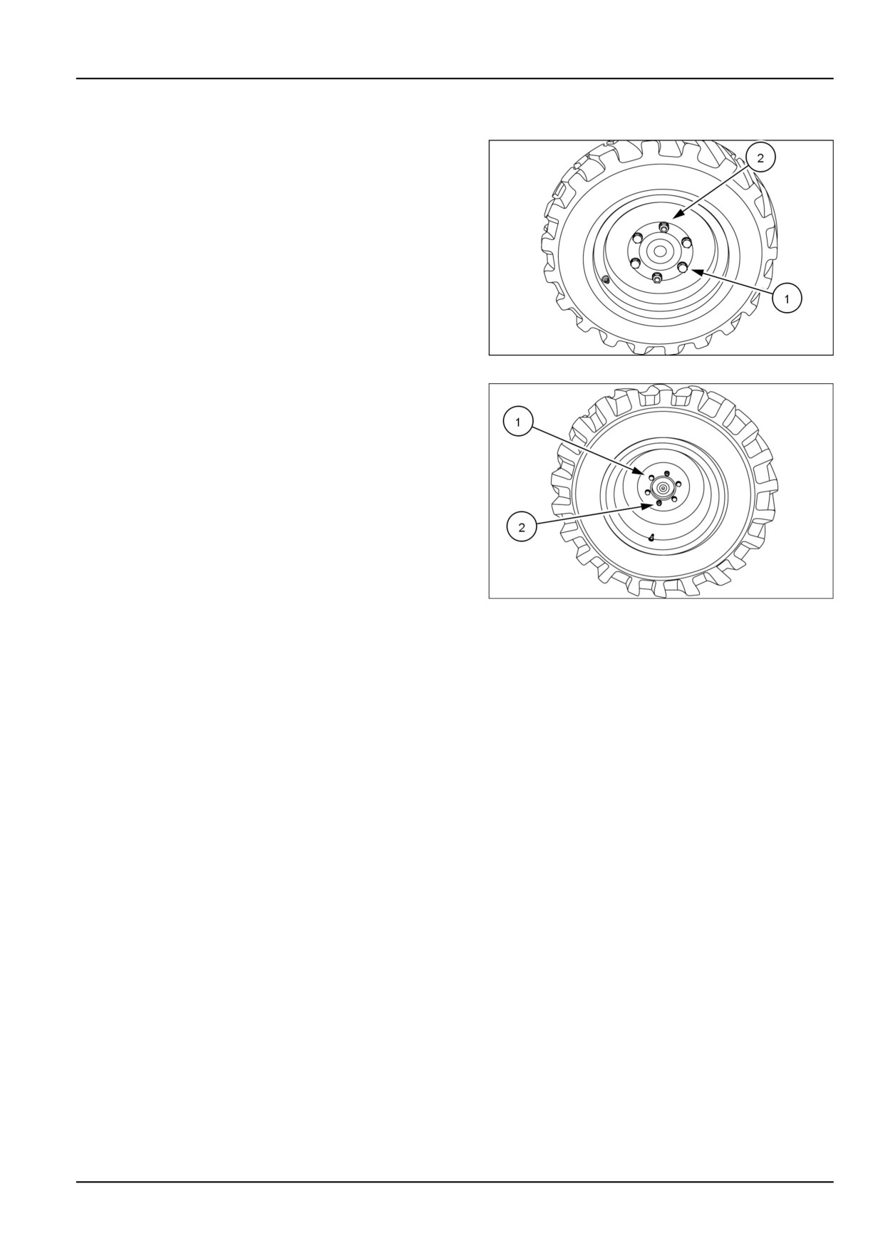
Tighten the wheel bolts (1) and nuts (2) to the specified
torque any time the wheel assembly is removed from the
tractor or the wheel bolts are loosened.
Front Wheel Torque
•
176 - 196 N·m (130 - 145 lb ft)
93100874
1
Rear Wheel Torque
•
176 - 196 N·m (130 - 145 lb ft)
NOTICE: Check and tighten wheel bolts (1) and nuts (2)
to proper torque specifications after the following hours of
use:
• First 5 hours
• First 50 hours
• Every 300 hours
93100875A
2
7-17
7 - MAINTENANCE
Every 50 hours
Grease fittings
NOTE: After every 50 hours of normal operation, apply a
good quality grease to the lubrication points listed below
(refer to the Recommended Lubricants chart). When oper-
ating under extremely dirty conditions, lubricate more fre-
quently than every 50 hours.
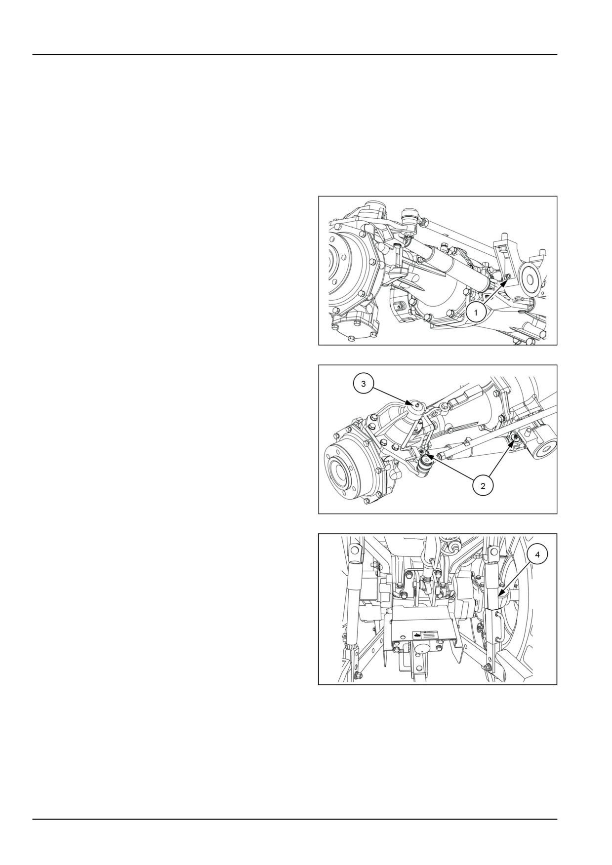
• Front Axle Pivot (1)
93100922
1
• Power Steering Cylinder (2) and steering arms (3)
(left and right)
93100921
2
•
3-Point Linkage (4)
To lubricate these points:
1. Wipe away all old grease and dirt from the lubrication
fittings to prevent dirt or foreign material from entering
as new grease is applied.
2. Use a grease gun to apply new grease to fittings.
3. Wipe away any excess grease.
NHIL12CT010120A
3
7-18
7 - MAINTENANCE
Transmission fluid level
NOTE: Check the transmission, rear axle, and hydraulic
system oil level after every 50 hours of operation.
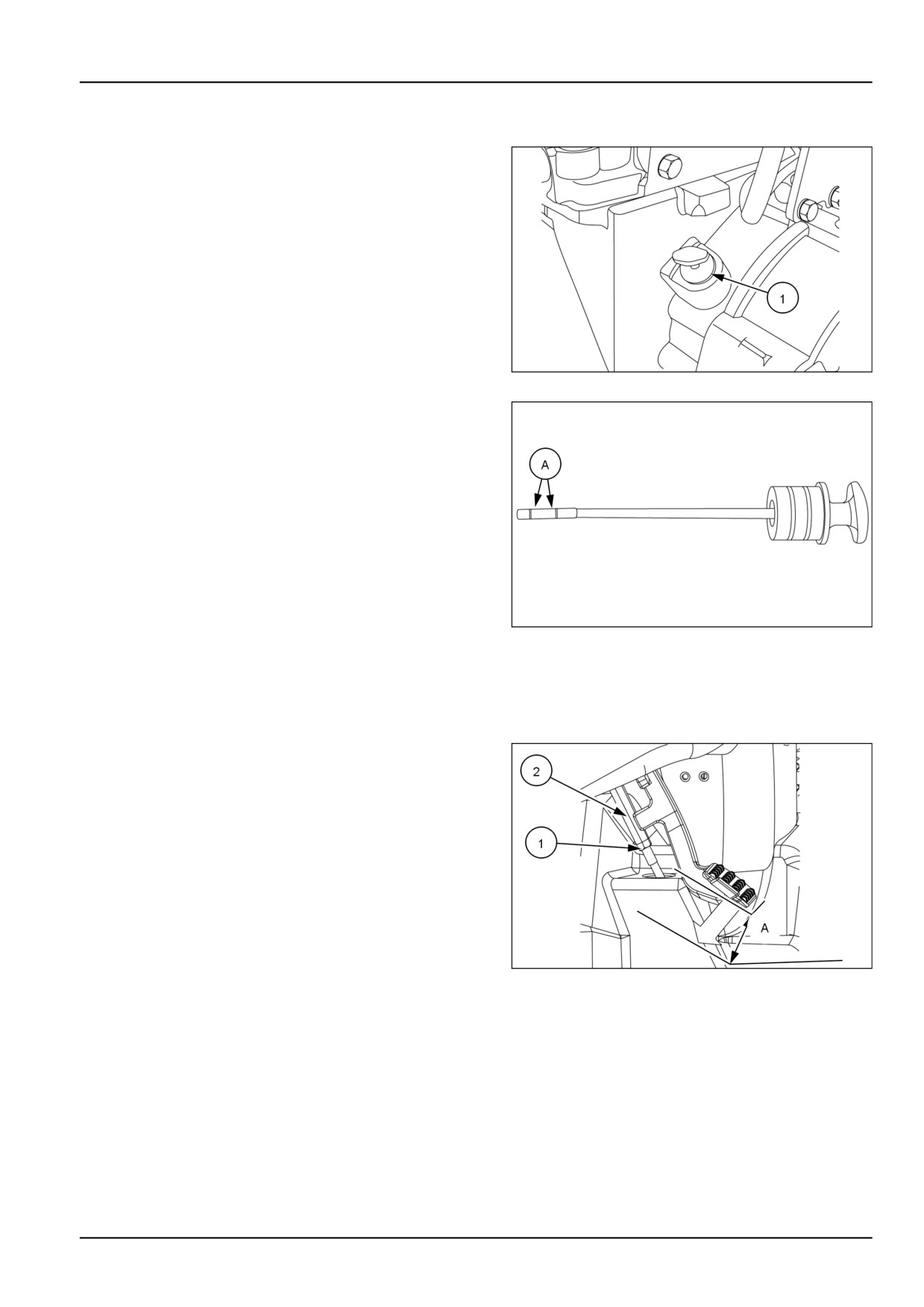
1. With the engine off and the tractor standing level, check
the oil level using the dipstick (1).
93099360
1
2. The oil is at the correct level when it reads between the
two marks (A) on the dipstick. If the level is low, add
NEW HOLLAND AMBRA MULTI G 134™ HYDRAULIC
TRANSMISSION OIL hydraulic oil through the dipstick
hole. Do not fill above the dipstick full mark.
3. Reinstall the dipstick.
93100904
2
Clutch pedal free play
NOTE: Check clutch pedal free travel after every 50 hours of operation.
Clutch pedal free travel should be maintained at A = 20 -
30 mm (0.79 - 1.18 in).
To adjust the clutch pedal:
1. Loosen lock nut (1) and rotate adjuster (2)
2. Tightening the adjuster will decrease the free play travel
and loosening the adjuster will increase the free play
travel.
3. Tighten the lock nut when the correct free play travel is
obtained
4. Check clutch for disengagement when clutch pedal is
fully depressed.
93100862
1
7-19
7 - MAINTENANCE
Brake pedal free play
To check brake pedal free play:
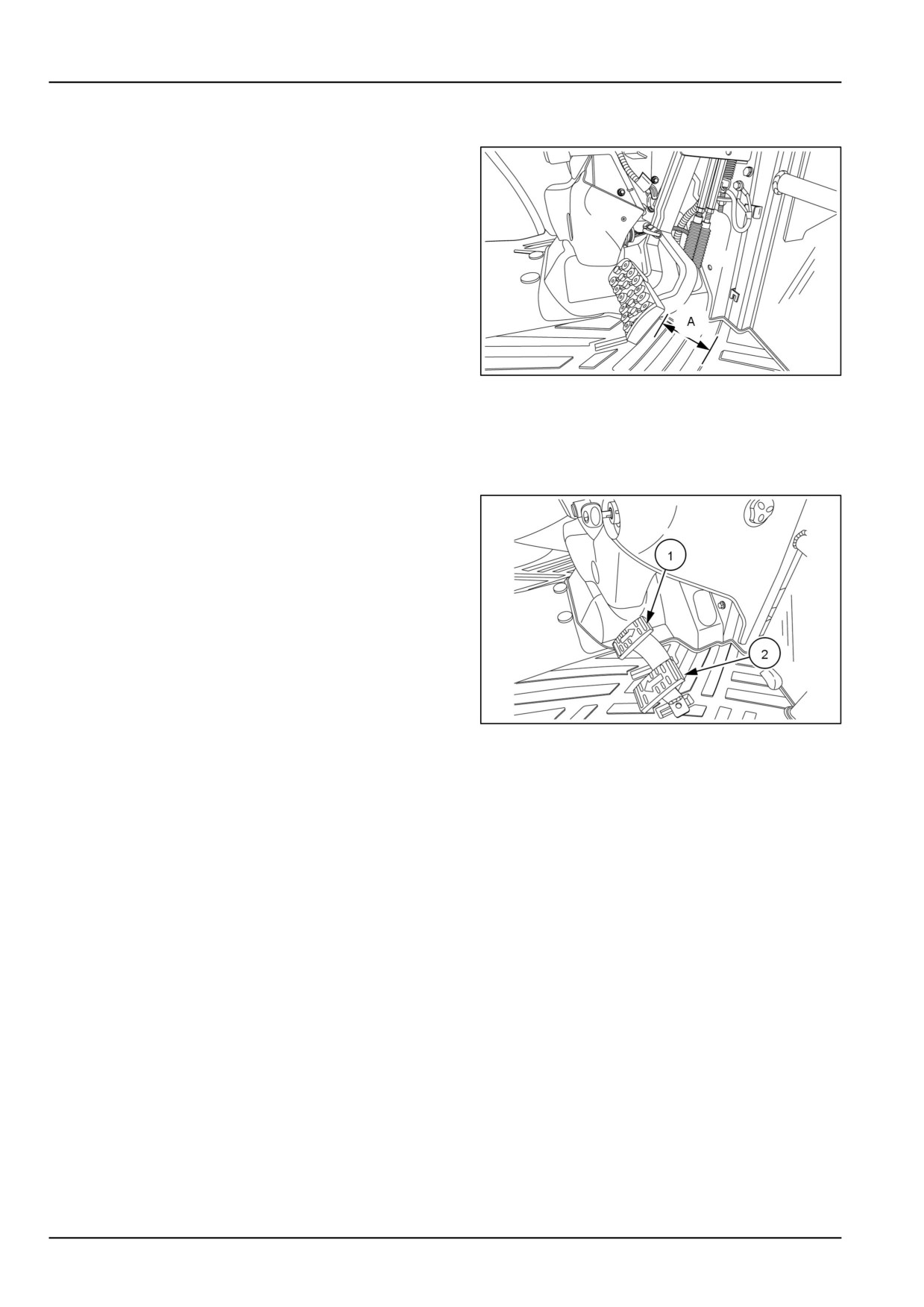
1. Depress brake pedal(s) until a resistance is felt.
2. Measure the brake pedal travel from the at rest position
to the position (A) that resistance is felt.
3. Brake pedal free play specification is 50.0 - 60.0 mm
(1.96 - 2.36 in)
4. If measured free play is more than the specification see
7-44 for adjustment procedure.
NHIL13CT01246AA
1
NOTE: Brake pedal free play should be equal for both pedals.
Hydrostatic transmission (HST) neutral adjustment
1. During the operation of the tractor, when the opera-
tor’s foot is removed from the forward (1) or reverse (2)
HST pedal, the tractor should stop and the rear wheels
should not rotate.
2. If the rear wheels rotate with the HST pedals in the
neutral position, the HST control linkage needs to be
adjusted.
3. To adjust HST control linkage see 7-35
NHIL13CT01172AA
1
7-20
7 - MAINTENANCE
Engine belts
NOTE: Check the condition of the fan and air pump belts after every 50 hours of operation. Check belt tension after
every 300 hours of operation.
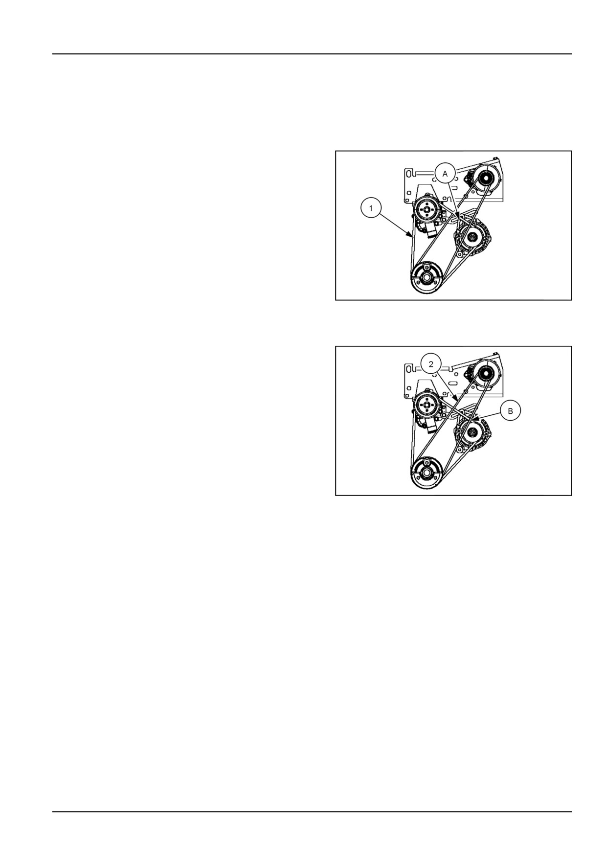
Fan and alternator belt
The belt- (1) that drives the cooling fan and alternator is
located at the front of the engine.
When 5 kg (11 lb) of pressure is applied midway between
the belt pulleys, a correctly tightened belt will deflect 5 mm
(0.2 in) .at point (A).
If the fan belt is slipping, fan efficiency is lowered, resulting
in the engine running too hot. or the alternator not charging
If the belt is too tight, the life of the alternator bearing will
be shortened. If the fan belt shows signs of cracking or
fraying, install a new one.
NHIL13CT01234AA
1
Air pump belt
The belt (2) that drives the engine air pump is located at
the front of the engine.
When 5 kg (11 lb) of pressure is applied midway between
the belt pulleys, a correctly tightened belt will deflect
10 mm (0.4 in) .at point (A).
If the air pump belt is slipping, pump efficiency is lowered.
Resulting in the (DPF) burning not operating at a high
enough temperature or difficulty in starting burner. If the
belt is too tight, the life of the pump bearing will be short-
ened. If the fan belt shows signs of cracking or fraying,
install a new one.
NHIL13CT01234AA
2
7-21
7 - MAINTENANCE
Tires and wheels
NOTE: Check tire pressure after every 50 hours of opera-
tion or weekly.
Tire inflation pressure affects the amount of weight a tire
can carry. Check the air pressure in your tractor tires, then
locate the tires in the 9-2 chart found in this manual. If nec-
essary, adjust the tire pressure, being careful not to over-
inflate or under inflate. Observe the following guidelines:
WARNING
Explosion hazard!
A tire can explode during inflation. Prop-
erly seat the tire before inflating. Never in-
crease air pressure beyond 240 kPa (35 psi)
to seat the bead on the wheel rim. Never
use force on a partially or fully inflated tire.
Do not exceed the inflation pressure recom-
mended by the tire manufacturer.
Failure to comply could result in death or
serious injury.
W0456A
• Do not inflate a tire above the maximum pressure
shown on the tire. If the tire is not marked, do not
exceed the maximum pressure shown in the Tire In-
flation chart found in this manual.
• Do not reinflate a tire that has been run flat or seri-
ously under inflated until the tire has been inspected
for damage by a qualified person.
• When checking tire pressure, inspect the tire for
damaged sidewalls and tread cuts. Neglected dam-
age leads to early tire failure.
7-22
7 - MAINTENANCE
If you must inflate or service tires, follow these safety
precautions to avoid injury or fatality:
•
Make sure the rim is clean and free of rust.
•
Lubricate both tire beads and rim flanges with soap
solution. Do not use oil or grease.
•
Use a clip-on tire chuck with a remote hose and
gauge. This allows the operator to stand clear of the
tire while inflating.
•
NEVER INFLATE TO OVER 241 kPa (35 psi) TO
SEAT BEADS. If beads have not been seated by the
time pressure reaches 241 kPa (35 psi), deflate the
assembly, reposition the tire on the rim, relubricate
both tire bead and rim flanges, and reinflate. Inflation
beyond 241 kPa (35 psi) with unseated beads may
break the bead or rim with explosive force sufficient
enough to cause serious injury.
•
After seating the beads, adjust inflation pressure to
recommended operating pressure.
•
Do not inflate a tire unless the rim is mounted on the
tractor or is secured so that it will not move if the tire
or rim should suddenly fail.
•
Do not weld, braze, otherwise repair, or use a dam-
aged rim.
•
Never attempt tire repairs on a public road or high-
way
•
Use jack stands or other suitable blocking to support
the tractor while repairing tires.
•
Ensure jack has adequate capacity to lift your tractor.
•
Place jack on a firm, level surface.
•
Do not place any part of your body beneath the trac-
tor or start the engine while the tractor is on the jack.
•
Before adding ballast to the tires, refer to 6-2, 6-2,
6-4, and 9-3.
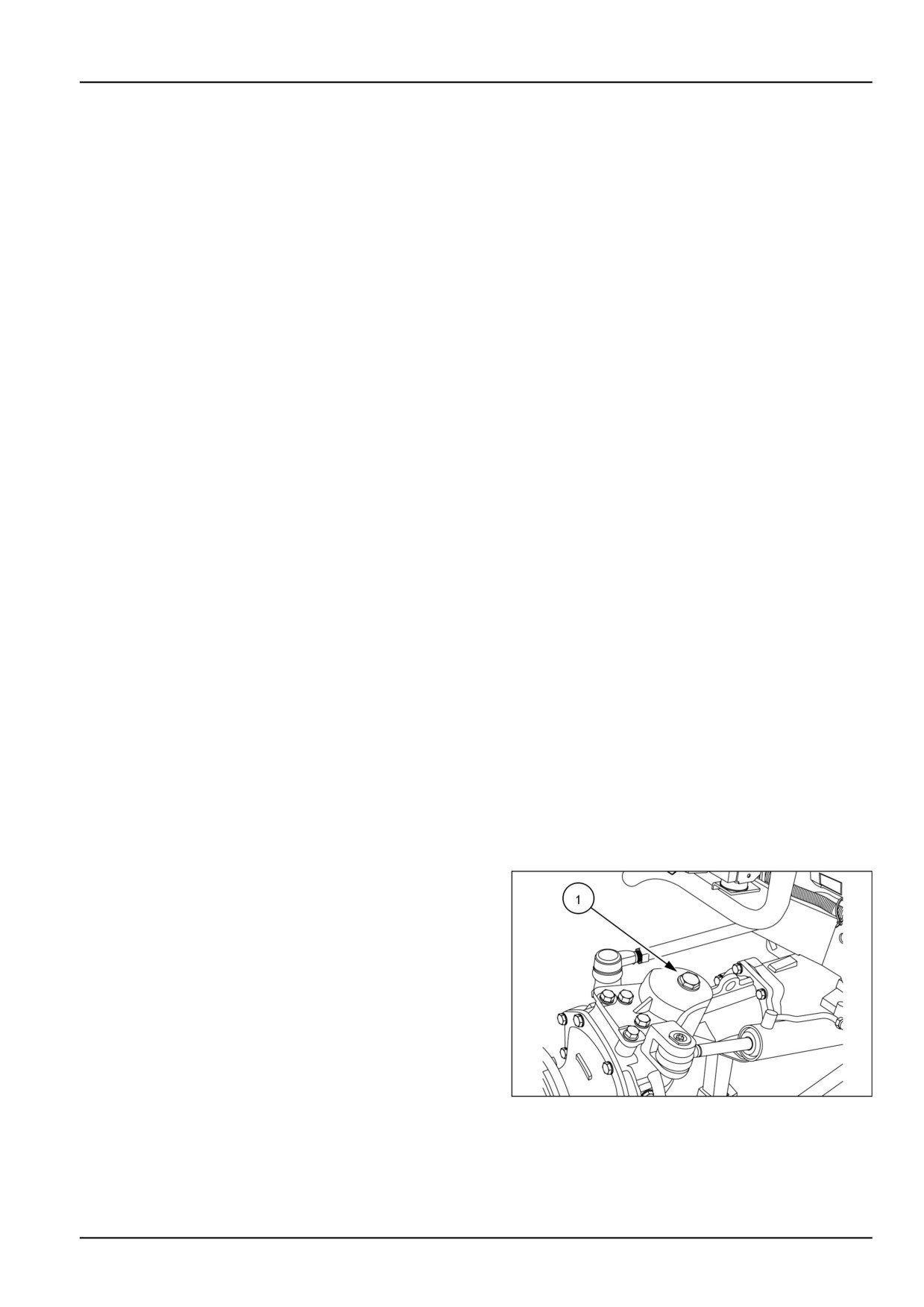
Front axle differential oil level
NOTE: Check the front axle differential case and final re-
duction gear case oil level after every 50 hours of operation.
1. With the tractor standing level and the engine off, check
the front axle oil level using the dipstick (1). located on
the left side of axle.
93100889
1
7-23
7 - MAINTENANCE
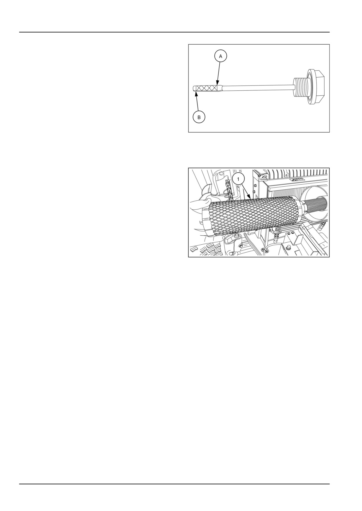
2. The oil is at the correct level when it reads between the
upper (A) and the lower (B) marks of the dipstick.
3. If capacity is low, add NEW HOLLAND AMBRA HYPOIDE
90 oil through the combined dipstick/filler plug. Do not
fill beyond the dipstick full mark, or the front axle and
differential housing will be overfilled.
4. Install the dipstick/filler plug.
93100902
2
Air cleaner - Primary element
NOTE: Clean the primary element after every 50 hours of
service. Extremely dusty conditions may require more fre-
quent service intervals.
1. Pull the primary element (1) from the canister. Clean
any loose dirt from the canister and inspect the end of
the canister for dirt which may prevent the new element
from sealing properly.
2. Clean the primary element using low air pressure (
2 Kg/cm² (30 psi) or less). Blow dust from the inside to
the outside of the element (opposite to normal air flow
through element).
NOTICE: Be careful not to rupture the filter element. Main-
NHIL13CT00995AA
1
tain a safe distance between the air nozzle and the filter
element when directing air up and down the clean air side
of the element pleats.
3. After cleaning the element, check the inner diameter
seals for damage. If damage is present, replace the
primary element.
4. Reinstall the primary element by inserting it into the
canister and pushing on the end of the element until
it is seated against the canister.
NOTE: Place a light inside the element to check for paper
leaks or for bonding of the paper to the end plate. If any
leaks are found, replace the element.
NOTE: If element is not inserted far enough into canister,
the end cap cannot be installed.
5. Place the end cap onto the canister body, push in on
end cap, and rotate clockwise. Make sure the end cap
is locked in place and not loose.
NOTICE: Never tap the element with hard objects or
against a hard surface. This may dent or break the ele-
ment end cap seals.
NOTICE: Failure to obtain a good seal between elements
and the canister may cause major engine damage.
7-24
7 - MAINTENANCE
Every 100 hours
Fuel filter
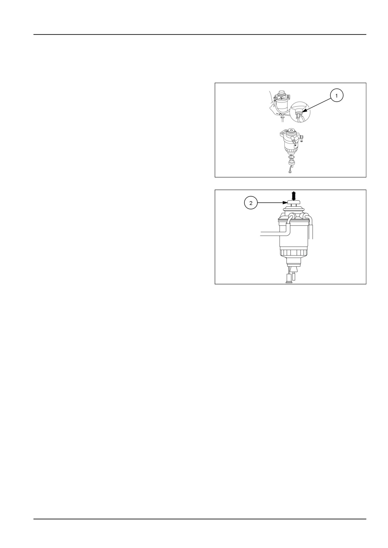
NOTE: The fuel filter should be drained after every 100
hours of operation.
1. Make sure there is adequate fuel in the fuel tank.
Loosen filter drain plug (1) and drain water from inside
of the filter.
93100920
1
2. Tighten drain plug when only fuel flows from the filter
base.
3. Bleed the air from the fuel filter, by pressing the manual
fuel feed pump (2) several times. The manual feed
pump will bleed the air back to the fuel tank. There
is no need to open any bleed ports in the fuel system.
NHIL13CT01251AA
2
7-25
7 - MAINTENANCE
Every 300 hours
Engine oil and filter
See 7-10
Hydraulic filter
See 7-14
Hydrostatic (HST) oil filter - HST system
See 7-15 .
Pre-fuel filter
See 7-12
Engine belts
See 7-21
Wheels bolt/nut
See 7-17
7-26