New Holland Boomer 41, Boomer 47 Compact Tractor. OPERATOR’S MANUAL (2014) - page 2
2 - SAFETY INFORMATION
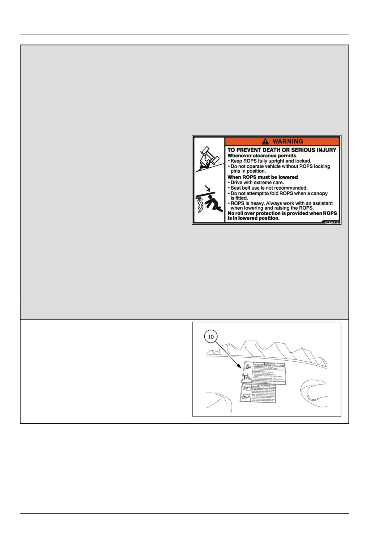
(10)
WARNING
TO PREVENT DEATH OR SERIOUS INJURY
Whenever clearance permits
•
Keep ROPS fully upright and locked
•
Do not operate vehicle without ROPS locking pins
in position
•
When ROPS must be lowered:
•
Drive with extreme care.
•
Seat belt use is not recommended.
•
Do not attempt to fold ROPS when a canopy is
40234715
20
fitted.
•
ROPS is heavy. Always work with an assistant
when lowering and raising the ROPS.
No roll over protection is provided when ROPS is
in lowered position
Failure to comply could result in death or serious
injury
Quantity: 1
English Part Number: MT40234715
(10) Location: On top of the left-hand fender.
83115222
21
2-22
2 - SAFETY INFORMATION
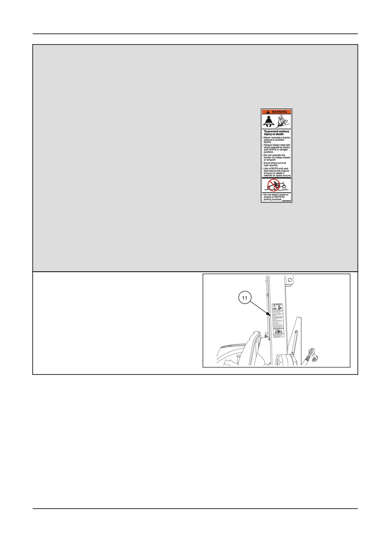
(11)
WARNING
To prevent serious injury or death:
•
Never operate a tractor without a certified ROPS.
•
Always fasten seat belt when operating tractor with
ROPS in upright position.
•
Do not operate the tractor on steep slopes or drop-
off.
•
Avoid sharp turns at high speeds.
•
Use of ROPS and seat belt reduce the chance of
injury or death if rollover or upset occur.
40234561
22
•
Do not attach ropes or chains to ROPS for pulling
purpose.
Failure to comply could result in death or serious
injury.
Quantity: 1
English Part Number: MT40234561
(11) Location: On the left-hand side of the ROPS frame.
83115221
23
2-23
2 - SAFETY INFORMATION
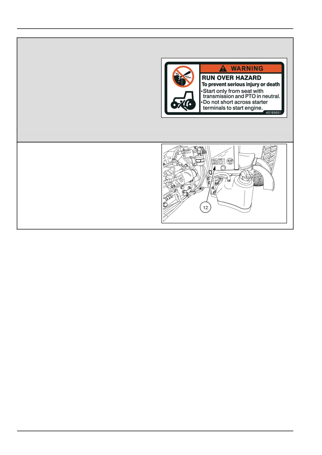
(12)
WARNING
RUN OVER HAZARD
To prevent serious injury or death:
•
Start only from seat with transmission and PTO in
neutral
•
Do not short across starter terminals to start en-
gine.
Failure to comply could result in death or serious
40195651
24
injury.
Quantity: 1
English Part Number: MT40195651
(12) Location: On the left-hand side of the operator’s
platform, at the front of the platform.
NHIL13CT01024AA
25
2-24
2 - SAFETY INFORMATION
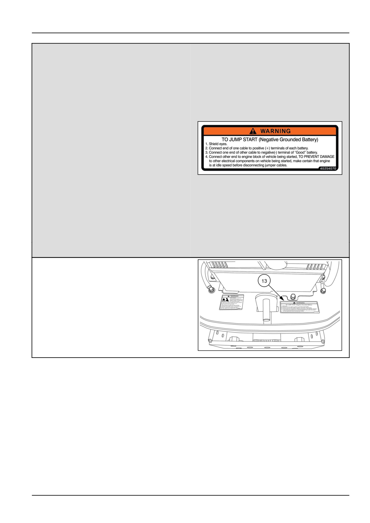
(13)
WARNING
•
TO JUMP START (Negative Grounded Battery )
1.
Shield eyes.
2.
Connect end of one cable to positive (+) terminals
of each battery.
3.
Connect one end of other cable to negative (-) ter-
minal of “Good” battery.
40254070
26
4.
Connect other end to engine block of vehicle be-
ing started, TO PREVENT DAMAGE to other elec-
trical components on vehicle being started, make
certain that engine is at idle speed before discon-
necting jumper cables.
Failure to comply could result in death or serious
injury.
Quantity: 1
English Part Number: MT40254070
(13) Location: Front left side of battery cradle.
NHIL13CT01208AA
27
2-25
2 - SAFETY INFORMATION
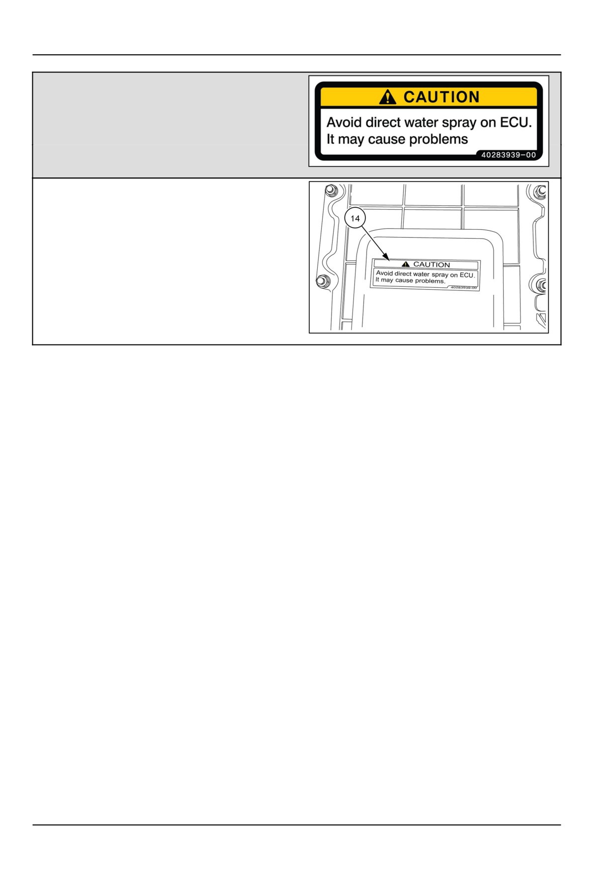
(14)
CAUTION
Avoid direct water spray on ECU.
It may cause problems.
Failure to comply may result in minor to moderate
injury.
Quantity: 1
English Part Number: MT40283939-00
40283939
28
(14) Location: On top face of ECU.
NHIL13CT00988AA
29
2-26
2 - SAFETY INFORMATION
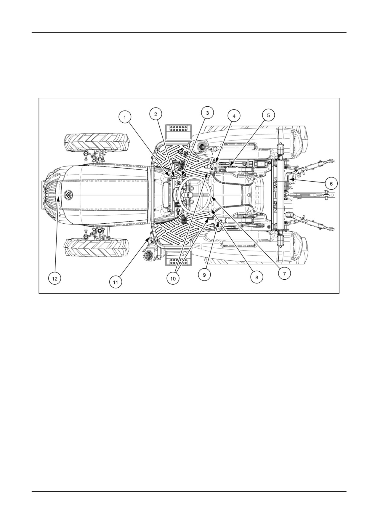
Instructional signs
The following instructional signs have been placed on your tractor in the area indicated. They are intended to instruct
you and those working with you. Please take this manual and walk around your tractor to note the content and location
of these signs. Review the signs and operating instructions detailed in this manual with the tractor operators. Keep
the signs clean and legible. If they become damaged or illegible, obtain replacements from your authorized NEW
HOLLAND dealer.
NHIL13CT01199FA
1
2-27
2 - SAFETY INFORMATION
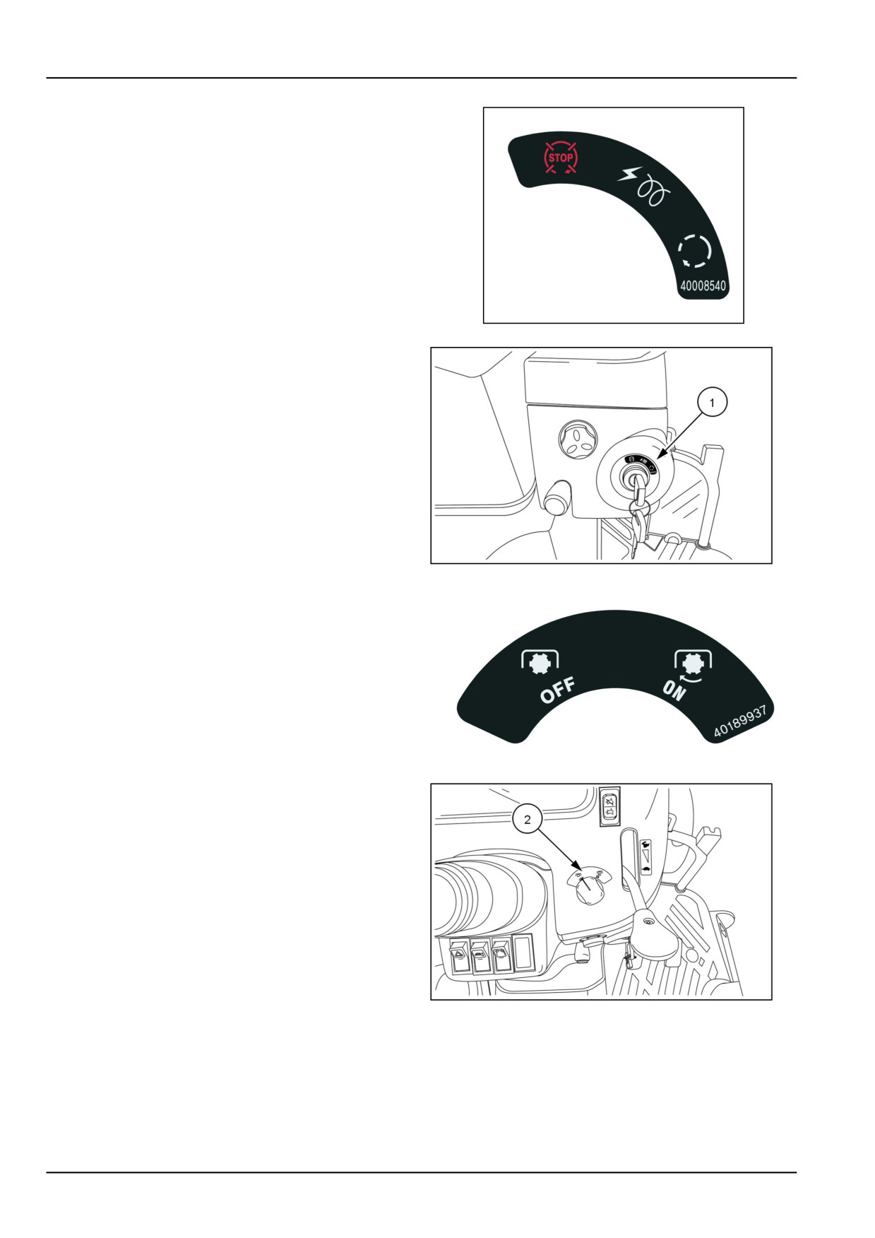
(1)
Key Switch
• English MT40008540
Location: Right-hand side of the rear hood panel.
40008540
2
NHIL13CT01006AA
3
(2)
PTO Switch
• English MT40189937
Location: Right-hand side of the dash panel.
40189937
4
NHIL13CT01005AA
5
2-28
2 - SAFETY INFORMATION
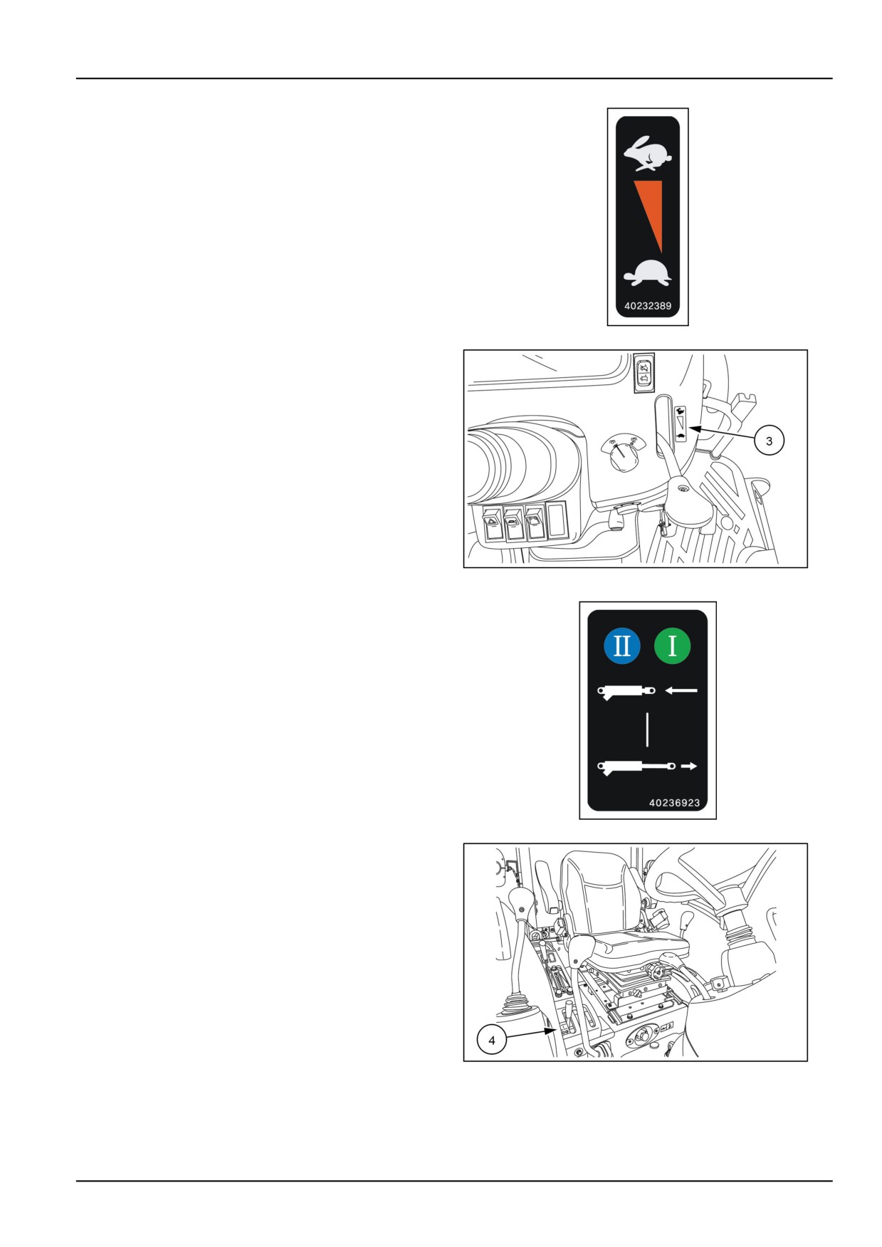
(3)
Hand Throttle Lever
• English MT40232389
Location: On the right-hand side of the dash panel.
40232389
6
NHIL13CT01005AA
7
(4)
Rear remote valve operation (Optional)
• English MT40236923
Location : Right side pod.
40236923
8
NHIL13CT01153AA
9
2-29
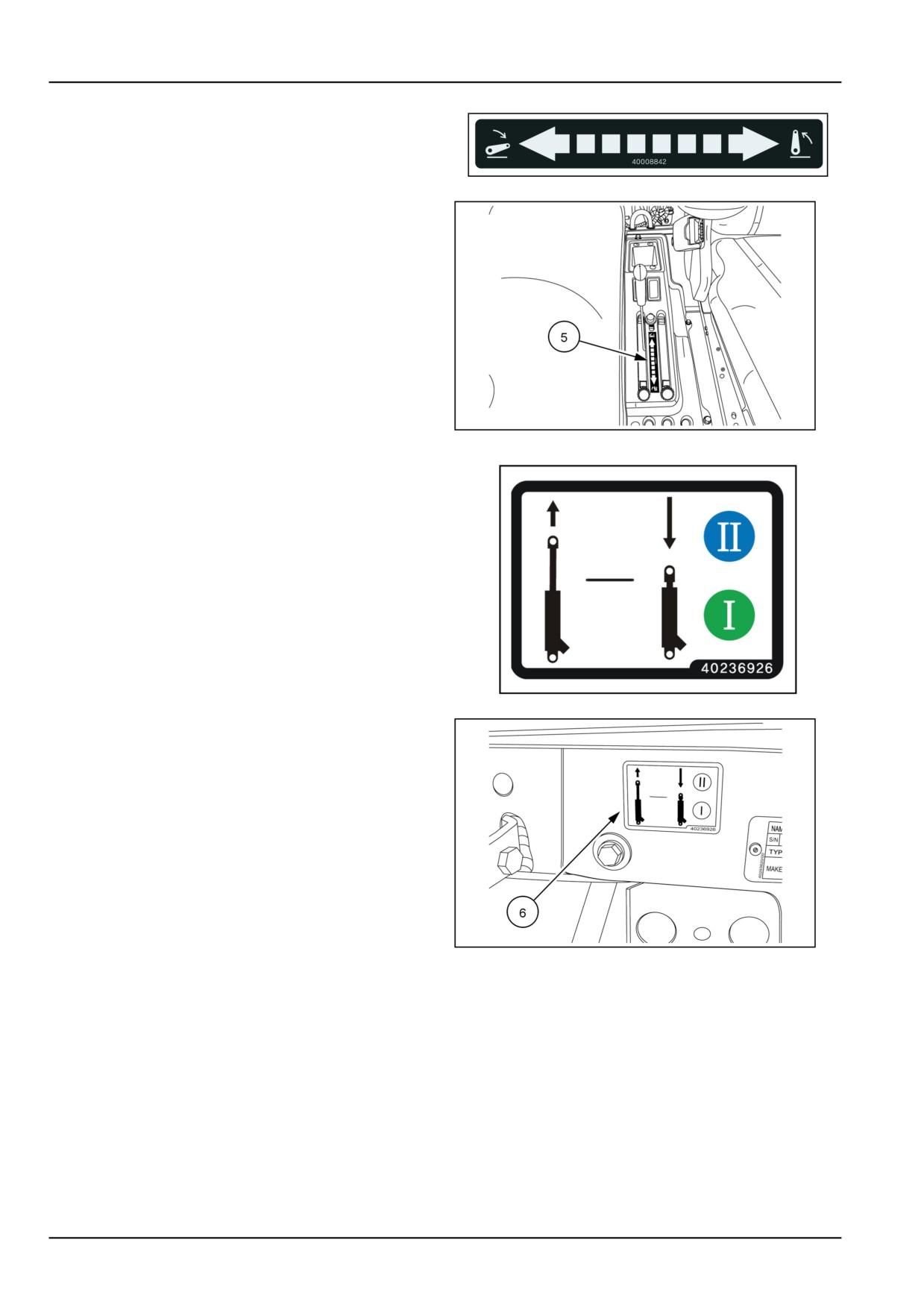
2 - SAFETY INFORMATION
(5)
Position control lever
• English MT40008842
40008842
10
Location: On the right-hand side control pod, next to the
drivers seat and right-hand fender.
NHIL13CT01014AA
11
(6)
Rear remote coupler operation
(Optional)
English MT40236926
Location : Right rear cross bar support.
40236926
12
NHIL13CT01102AA
13
2-30
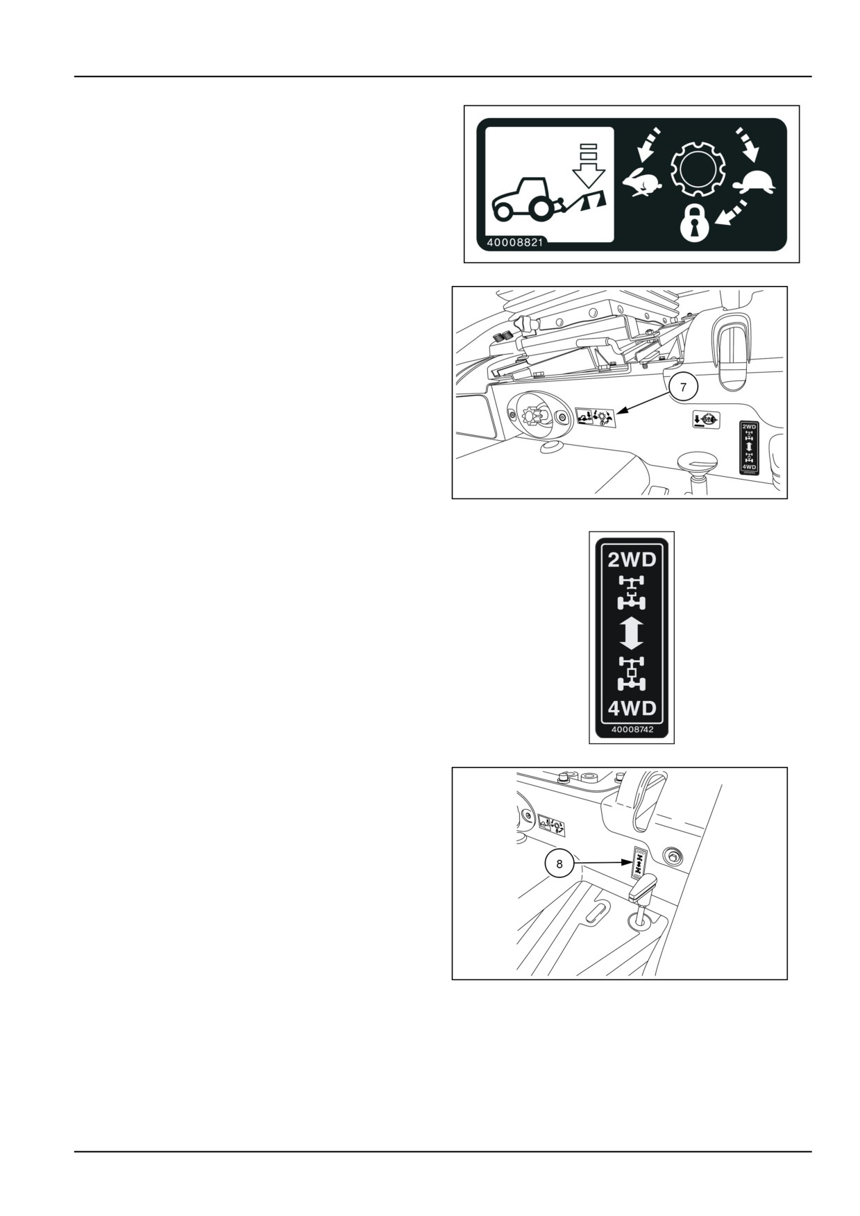
2 - SAFETY INFORMATION
(7)
Drop rate control valve
• English MT40008821
Location: Below the drivers seat, near the park brake.
40008821
14
NHIL13CT01379AA
15
(8)
4WD lever
• English MT40032976
Location: On the left rear operator’s platform.
40008742
16
NHIL13CT01175AA
17
2-31
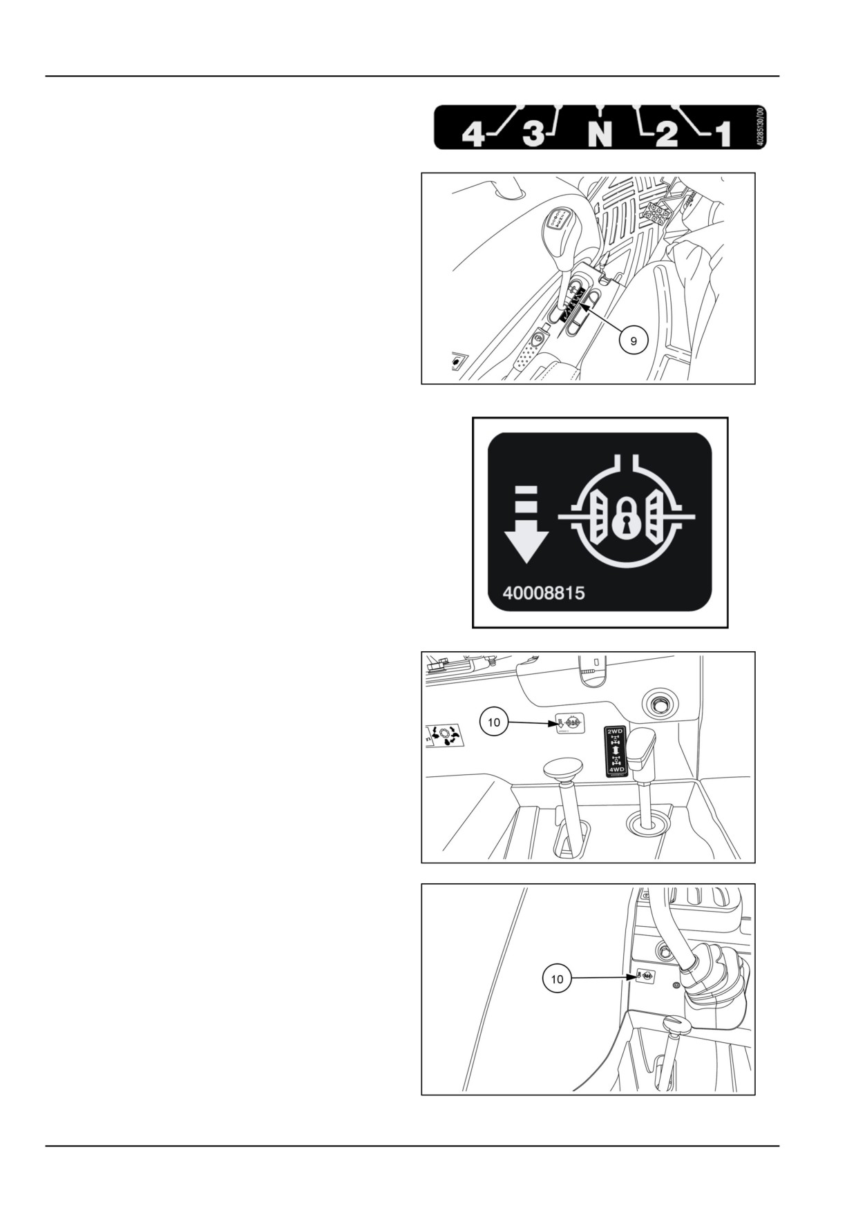
2 - SAFETY INFORMATION
(9)
Range gear lever (Gear transmission)
• English MT40285130
40285130
18
Location: Left side control pod.
NHIL13CT01353AA
19
(10)
Location: HST - Left rear operator’s platform.
(Refer to figure 21).
(10) Location: Mechanical - Right rear operator’s plat-
form.
(Refer to figure 22 )
40008815
20
NHIL13CT01361AA
21
NHIL13CT01240AA
22
2-32
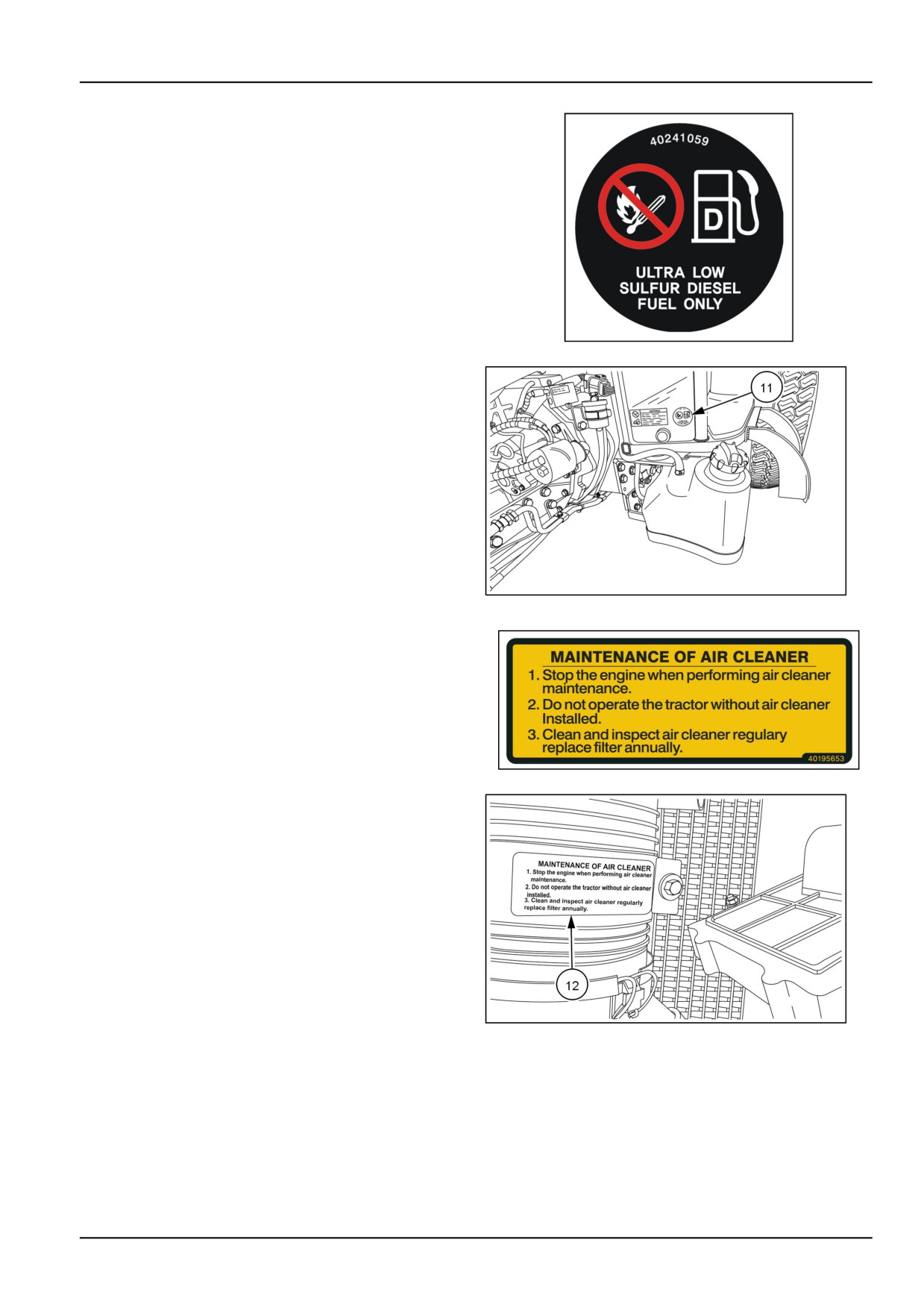
2 - SAFETY INFORMATION
(11)
Fuel
Ultra low sulfur diesel fuel only
• English MT40241059
Location: Left side, on platform shield above the fuel tank.
40241059
23
NHIL13CT01024AA
24
(12)
MAINTENANCE OF AIR CLEANER
1. Stop the engine when performing air cleaner
maintenance.
2. Do not operate the tractor without air cleaner installed.
3. Clean and inspect air cleaner regularly
Failure to comply could result in machine damage.
• English MT40195653
40195653
25
Location: On top of the air cleaner.
NHIL13CT00992AA
26
2-33
2 - SAFETY INFORMATION
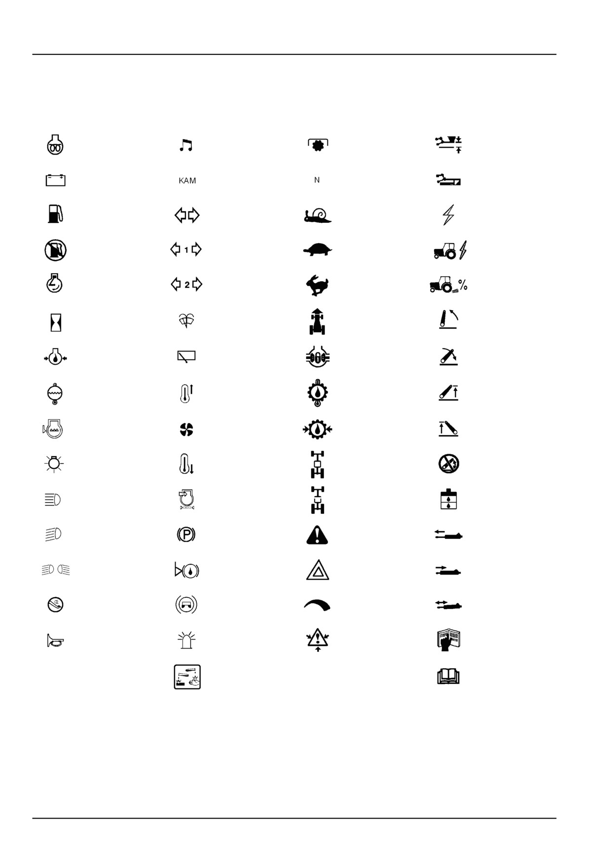
International symbols
As a guide to the operation of the machine, various universal symbols have been utilized on the instruments, controls,
switches, and fuse box. The symbols are shown below with an indication of their meaning.
Thermostart
Position
Radio
PTO
starting aid
Control
Alternator
Keep alive
Transmission
Draft
charge
memory
in neutral
Control
Creeper
Accessory
Fuel level
Turn signals
gears
socket
Automatic
Turn signals
Slow or
Implement
Fuel shut-off
-one trailer
low setting
socket
Engine speed
Turn signals
Fast or high
%age
(rev/min x 100)
-two trailers
setting
slip
Front wind-
Ground
Hitch raise
Hours recorded
shield
speed
(rear)
wash/wipe
Rear wind-
Engine oil
Differential
Hitch lower
shield
pressure
lock
(rear)
wash/wipe
Rear axle
Engine coolant
Heater temp-
Hitch height
oil tem-
temperature
erature control
limit (rear)
perature
Coolant
Transmission
Hitch height
Heater fan
level
oil pressure
limit (front)
FWD
Hitch dis-
Tractor lights
Air conditioner
engaged
abled
Hydraulic and
Headlamp
Air filter
FWD dis-
transmission
main beam
blocked
engaged
filters
Headlamp
Parking
Remote
Warning!
dipped beam
brake
valve extend
Brake fluid
Hazard
Remote
Work lamps
level
warning lights
valve retract
Stop
Trailer
Variable
Remote
lamps
brake
control
valve float
Malfunction!
Roof
Pressurized!
Horn
See Operator's
beacon
Open carefully
Manual
Warning !
Malfunction!
Corrosive
(alter-
substance
native symbol)
2-34
3 - CONTROLS AND INSTRUMENTS
3 - CONTROLS AND INSTRUMENTS###_3_###
OPERATOR'S SEAT
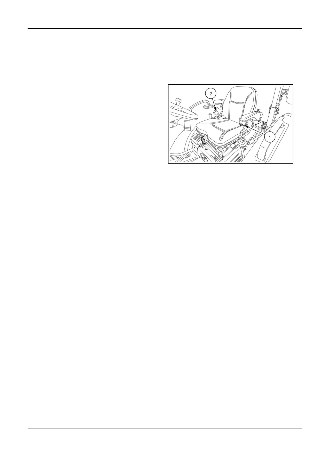
Seat belt
The retractable male end of the seat belt (1) is located on
left-hand side of the seat. To extend length of seat belt,
pull out on male end until correct length is obtained. To
latch seat belt, insert male end into the buckle (2) located
on right-hand side of the seat. Make sure belt is securely
buckled and belt length is adjusted correctly for size of
operator.
Use soap and water to clean the seat belt if necessary.
Do not use carbon tetrachloride, naphtha, etc., as these
substances will weaken the webbing. Additionally, do not
bleach or dye the webbing, as these products will also
weaken the webbing.
NHIL13CT01165AA
1
Replace the seat belt if it becomes damaged or worn.
3-1
3 - CONTROLS AND INSTRUMENTS
Seat controls
Adjusting the tractor seat
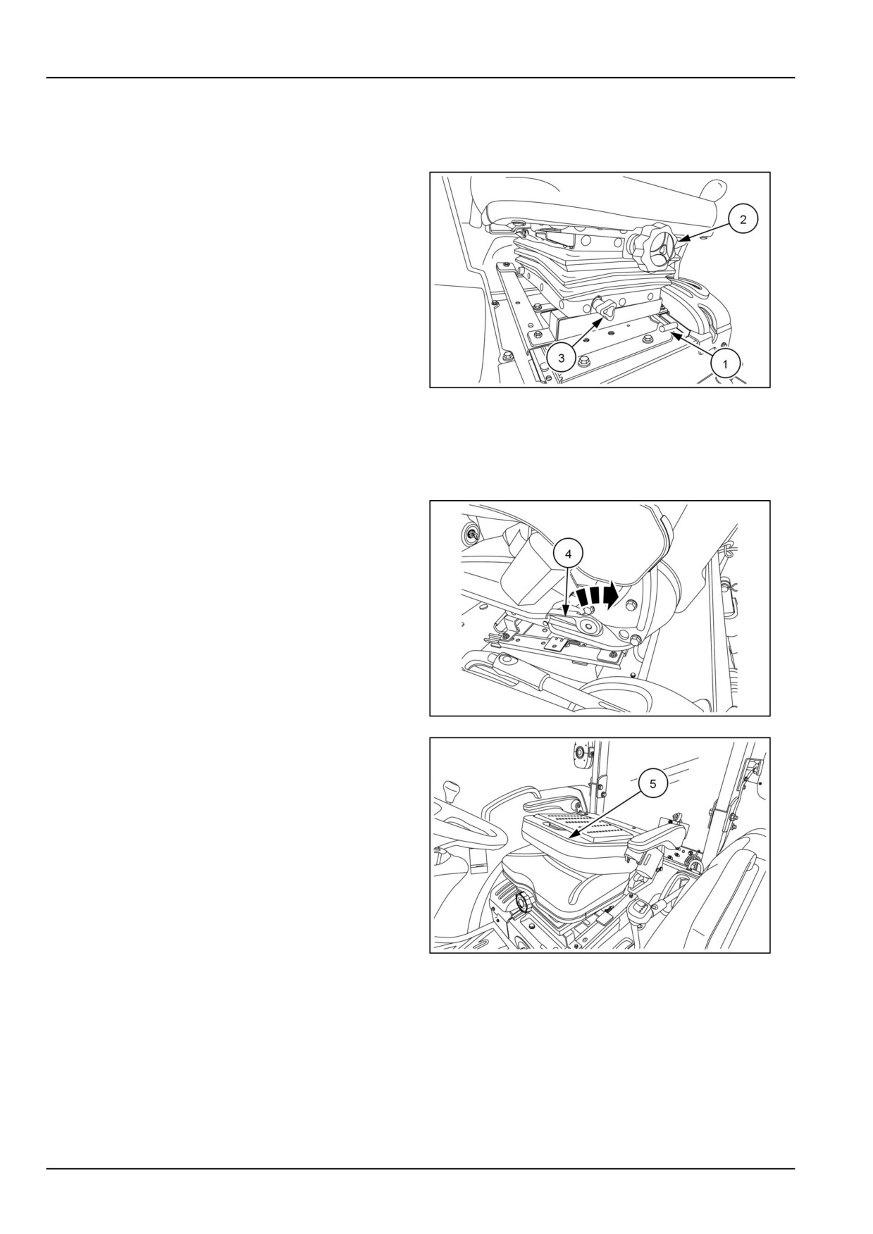
Your tractor is equipped with an adjustable suspension
seat.
To move the seat forward or backwards, raise the adjust-
ment lever (1). After the seat is adjusted, release the ad-
justment lever.
To adjust the seat suspension, turn the weight adjustment
knob (2). Rotate the knob clockwise for a firmer ride or
counter-clockwise for a softer ride.
NOTE: Before adjusting seat height, release tension on
seat suspension by rotating knob (2) counter-clockwise.
To adjust the seat height, turn the height adjustment
NHIL13CT01016AA
1
knob (3). Turn the knob clockwise to lower the seat and
counter-clockwise to raise the seat.
Rotate seat back latch (4) rearward to release latch and
allow seat back (5) to tilt forward.
Seat cleaning
For cleaning of vinyl, plastic, and rubber parts, use
"ONLY" a mild car washing soap and water, as described
below:
"First remove any loose dirt by rinsing with clean water.
Mix a warm, mild liquid CAR WASHING soap solution (1
NHIL13CT01162AA
2
part soap and 99 parts water). Then using a sponge or
soft cloth, apply the soap solution to the part. Allow the
solution to soak for a few minutes to loosen the dirt. Fi-
nally, rinse the part with clean water to remove the dirt,
and any solution residue. If all the dirt does not come off,
repeat the procedure."
NHIL13CT01164AA
3
3-2
3 - CONTROLS AND INSTRUMENTS
Roll Over Protective Structure (ROPS)
WARNING
WARNING
Misuse hazard!
Crushing hazard!
Your machine is equipped with an operator
Always wear the seat belt when operating the
protective structure. DO NOT weld, drill holes,
machine with the Roll Over Protective Struc-
attempt to straighten, or repair the protective
ture (ROPS) in the upright position. If the
structure. Modification in any way can reduce
ROPS is in the folded position, the seat belt
the structural integrity of the structure.
should not be used. Raise the ROPS and wear
Failure to comply could result in death or se-
the seat belt as soon as conditions allow.
rious injury.
Failure to comply could result in death or se-
W0001B
rious injury.
W0462A
WARNING
WARNING
Roll-over hazard!
A folded Roll-Over Protective Structure
Roll-over hazard!
(ROPS) does not provide roll-over protection.
Always pull from the drawbar. DO NOT attach
Do not operate the machine with the ROPS
chains or ropes to the Roll Over Protective
folded as a standard operating mode. Raise
Structure (ROPS) for pulling purposes, as the
the ROPS immediately after low clearance
machine could tip over. When driving through
use or transport.
door openings or under low overhead objects,
Failure to comply could result in death or se-
make sure there is sufficient clearance for the
rious injury.
ROPS.
W0938A
Failure to comply could result in death or se-
rious injury.
W0463A
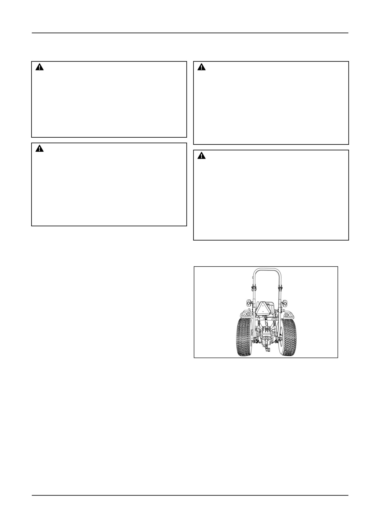
A Rollover Protective Structure (ROPS) and seat belts are
standard equipment on this tractor at the time of factory
assembly. If the ROPS was removed by the original pur-
chaser or has been removed, it is recommended that you
equip your tractor with a ROPS and seat belts.
ROPS are effective in reducing injuries in the event of
tractor overturn. Overturning a tractor without a ROPS
installed can result in serious injury or death. The Rollover
Protective Structure and seat belts are available from your
NEW HOLLAND Dealer.
Additionally, the safety offered by the ROPS and seat belt
is minimized if your seat belt is not buckled. Always use
NHIL13CT01167AA
1
your seat belt when the ROPS is in the "UP" position, it
can save your life.
3-3
3 - CONTROLS AND INSTRUMENTS
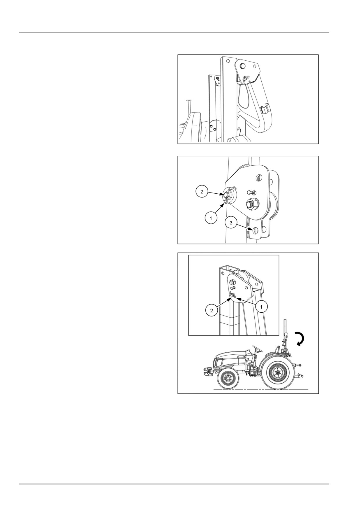
Foldable ROPS
A foldable Rollover Protective Structure, is factory in-
stalled. Operate with this ROPS in the "UP" position
whenever possible. Use the ROPS in the "folded" posi-
tion only when absolutely necessary.
NHIL13CT01021AA
2
ROPS Folding Procedure
To fold the ROPS into the "DOWN" position
1. Remove retaining clip (1) from the pin (2) and remove
pin from the latching bracket, on both sides of the
ROPS.
2. Rotate the top part of the ROPS downward until the
brackets contact the ROPS uprights.
3. Reinstall pin (2) into lower retaining hole (3).
4. Secure the pin (2) with the retaining clip (1).
93099328
3
NHIL12CT01017GA
4
3-4
3 - CONTROLS AND INSTRUMENTS
FORWARD CONTROLS
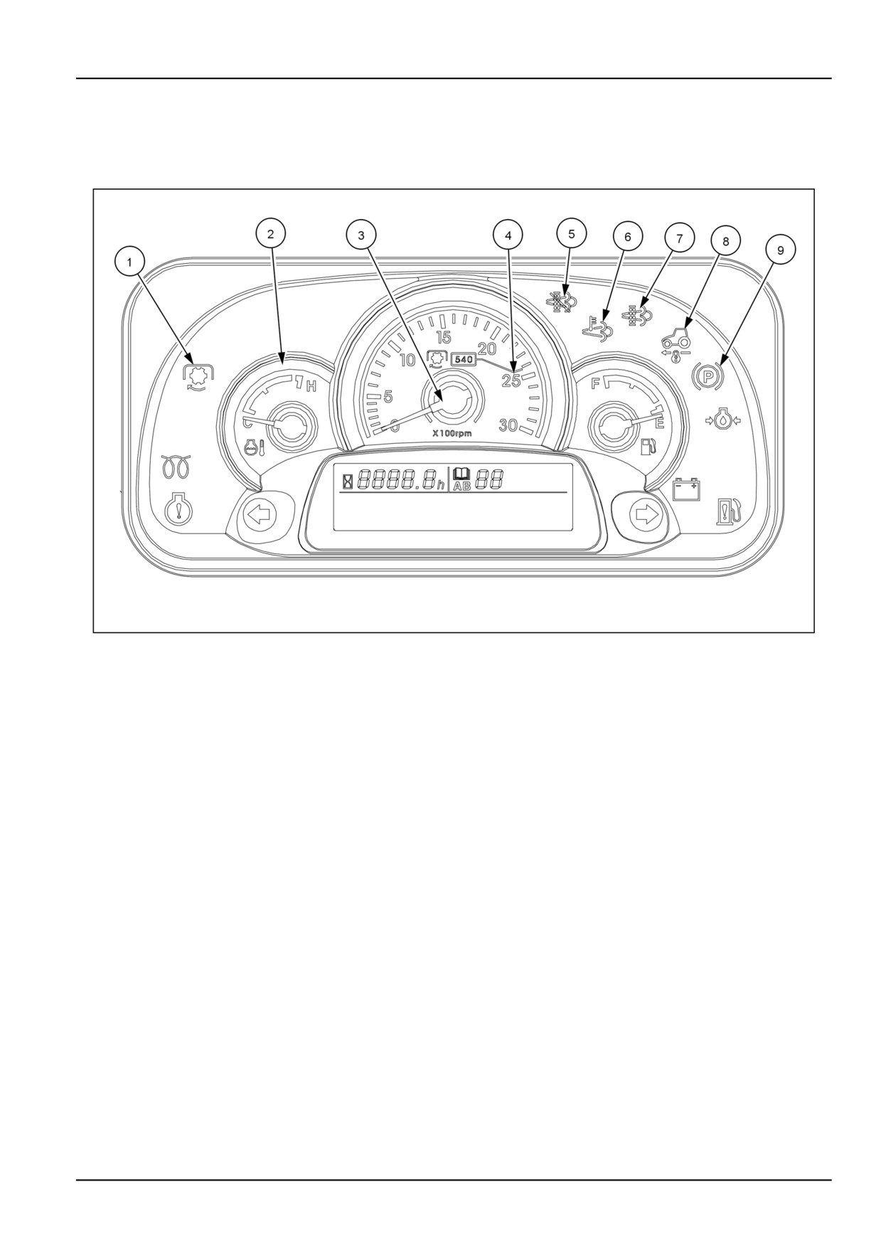
Instrument panel
NHIL14CT00054FA
1
1. PTO Indicator Light - When either the rear or mid
the (DPF) switch is placed in the inhibited position,
PTO is engaged, the indicator will be illuminated am-
to indicate the regeneration of the (DPF) is stopped.
ber with the key in the "START" or "ON" positions.
6. Diesel Particulate Filter (DPF) Temperature Indicator
2. Temperature Gauge - Indicates coolant temperature.
Light - This indicator light will be illuminated when
It is activated when the key switch is turned to the
the engine exhaust temperature is sufficient for the
"ON" position. The gauge will register cold with the
regeneration of the (DPF) to start.
key switch in the "OFF" position. If the needle regis-
7. Diesel Particulate Filter (DPF) Regeneration Indica-
ters in the white range of the gauge, this indicates a
tor Light - This indicator light will be illuminated either
normal operating temperature. If the needle moves
continuous or blinking, when the regeneration of the
to the red portion of the gauge, this indicates an over-
(DPF) is in operation. The regeneration is started
heated condition. Stop the tractor engine immedi-
when the (DPF) soot load is over 60% or every four
ately and investigate the cause.
hours of operation and the engine exhaust tempera-
3. Tachometer - Registers engine rpm (Revolutions Per
ture is at a sufficient temperature for regeneration to
Minute). The gauge is marked in increments of 100
start.
and will return to zero when the engine is not running.
8. Cruise Control Indicator Light (HST only) - Illumi-
4. PTO Speed Indicator - Determined by the position
nates amber with the key switch in the "ON" position
of the needle on the tachometer. The tachometer is
and the cruise control rocker switch is engaged.
marked to indicate 540 RPM of PTO. If the needle
9. Park Brake Indicator Light - Illuminates if the park
registers above the 540 RPM mark, this indicates a
brake is engaged with the key switch rotated from
dangerous over speed condition, and the engine rpm
the "OFF" position.
should be reduced immediately.
5. Diesel Particulate Filter
(DPF) Inhibited Indicator
Light - This indicator light will be illuminated when
3-5
3 - CONTROLS AND INSTRUMENTS
NHIL14CT00054FA
2
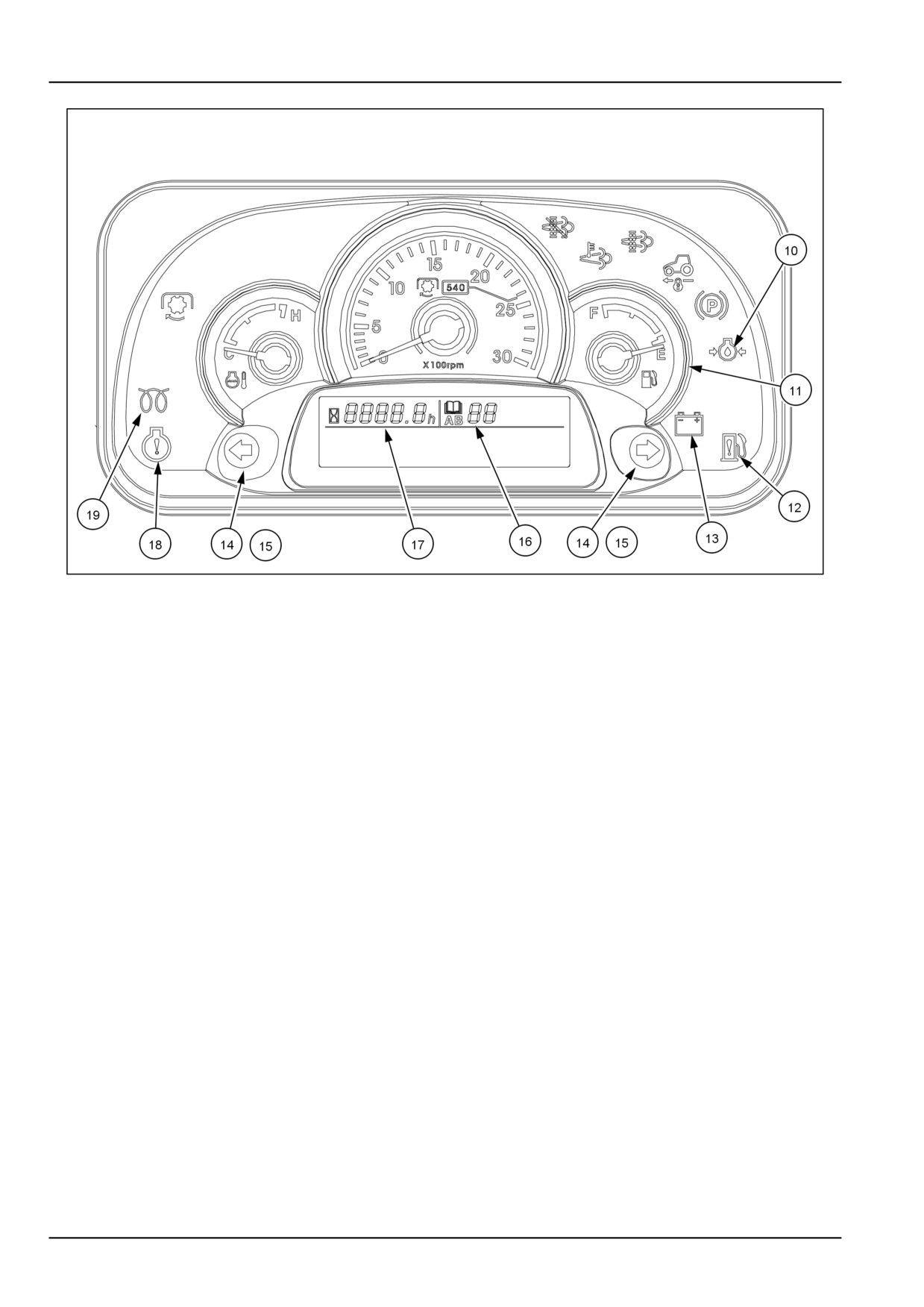
10.
Engine Oil Pressure Warning Light - Illuminates with
15.
Flasher Turn Lights - Operate when the multifunction
the key switch in the "ON" position and remains il-
switch lever is moved upwards for right turns the right
luminated for a short period of time after the engine
arrow will flash and moved downwards for left turns
is started. The light indicates low engine oil pres-
the left arrow will flash. The key switch has to be in
sure only and goes out when sufficient oil pressure
the "ON" or "START" positions.
is present at the oil sender. If the bulb becomes il-
16.
Engine fault codes display - Displays any engine fault
luminated during operation, stop the tractor engine
codes that may occur. Fault code will be displayed
immediately and investigate the cause.
as AB##. See 3-7 for list of engine fault codes.
11.
Fuel Gauge - Indicates the amount of diesel fuel re-
17.
Hour Meter - Records the hours and portions of hours
maining in the tank. The gauge is activated when
that your tractor has been operated regardless of en-
the key switch is in the "ON" position. It will register
gine RPM. Use the hour meter as a guide to deter-
"empty" with the key switch in the "OFF" position.
mine hourly service and maintenance intervals.
12.
Fuel Filter Warning Indictor Light - Illuminates when
18.
Engine Warning Indicator Light - Illuminates when
there is a restriction or excess water in the fuel filter.
there is a fault detected in the engine control system.
When this indicator illuminates the engine will shut
This indicator light will be illuminated either continu-
off automatically. Service of the fuel filter will be re-
ous or blinking, depending on engine fault. See 4-2
quired.
for more detail explanation of engine warning indictor
13.
Battery Charge Warning Light - Illuminates when the
light operation.
key switch is in the "ON" position and goes out when
19.
Cold Starting Indicator Light - Illuminates when the
the engine is started. If this bulb becomes lit during
key switch is first turned to the "ON" position. The
operation, it indicates that the charging system is not
illumination time will vary from three to twelve sec-
operating normally.
onds, depending on the ambient temperature. When
14.
Flasher Warning Lights - Operate when the multi-
the indicator light is illuminated, the glow plugs are
function switch is placed in the hazard or road lights
heating the engine precombustion chambers.
position, regardless of the key switch position. Use
the flasher warning lights, road lights when traveling
on public roads, day or night.
3-6
3 - CONTROLS AND INSTRUMENTS
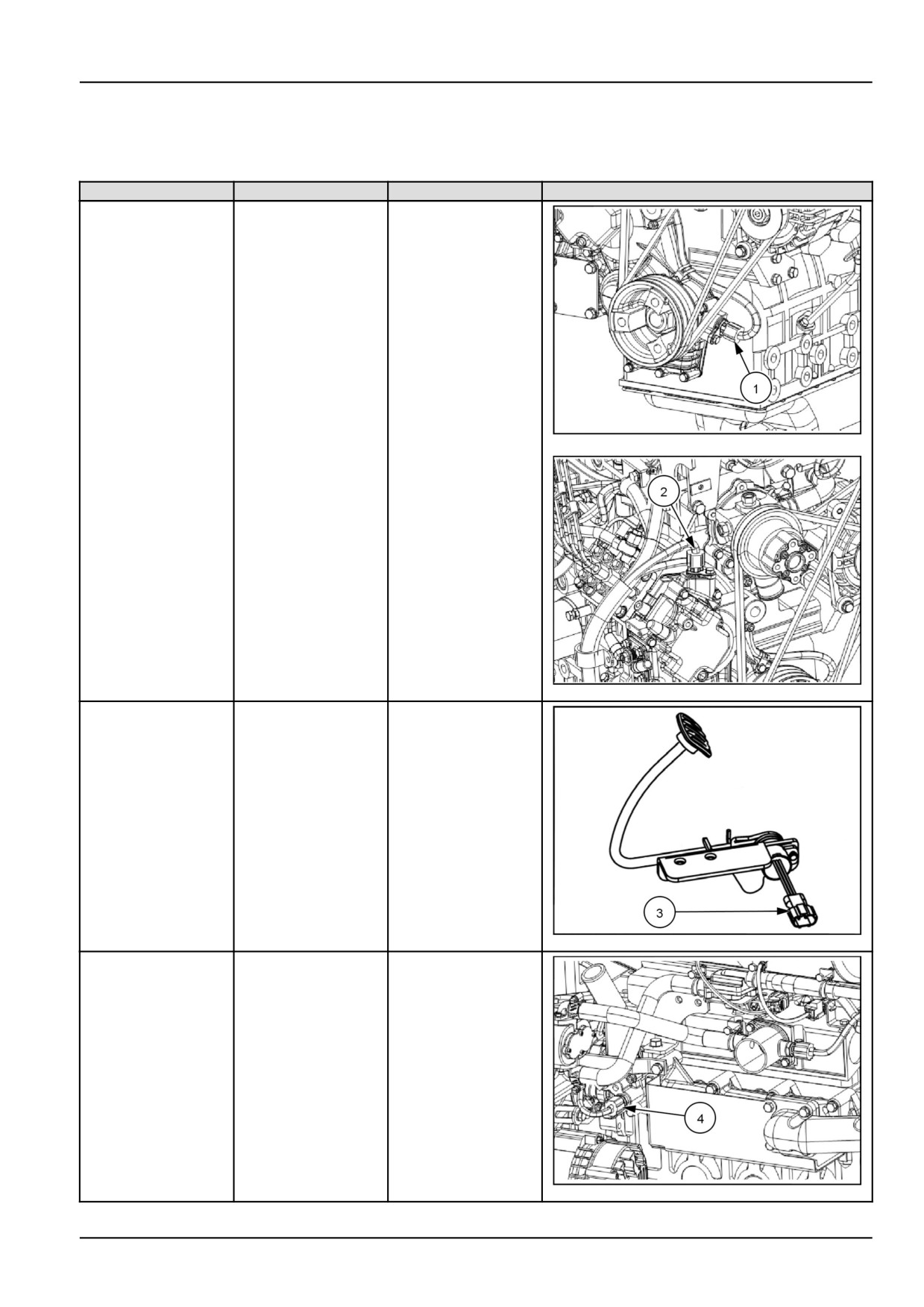
Engine fault codes display
Engine fault codes
Fault code
Possible cause
Check
Location
ABO2
Main speed sensor
Connector
(1)
connection
Sub speed sensor (2)
Wiring harness for
open or shorted
circuit
NHIL14CT00055AC
1
NHIL14CT00056AC
2
AB04
Foot throttle pedal
Normal sensor signal
position sensor (3)
0.2 to 4.25 volts
(Gear transmission
Connector
tractors only)
connection
Wiring harness for
open or shorted
circuit
NHIL14CT00061AC
3
AB07
Engine coolant
Normal sensor signal
temperature sensor
0.11 to 25.4 ohms
(4)
Connector
connection
Wiring harness for
open or shorted
circuit
NHIL14CT00057AC
4
3-7
3 - CONTROLS AND INSTRUMENTS
Fault code
Possible cause
Check
Location
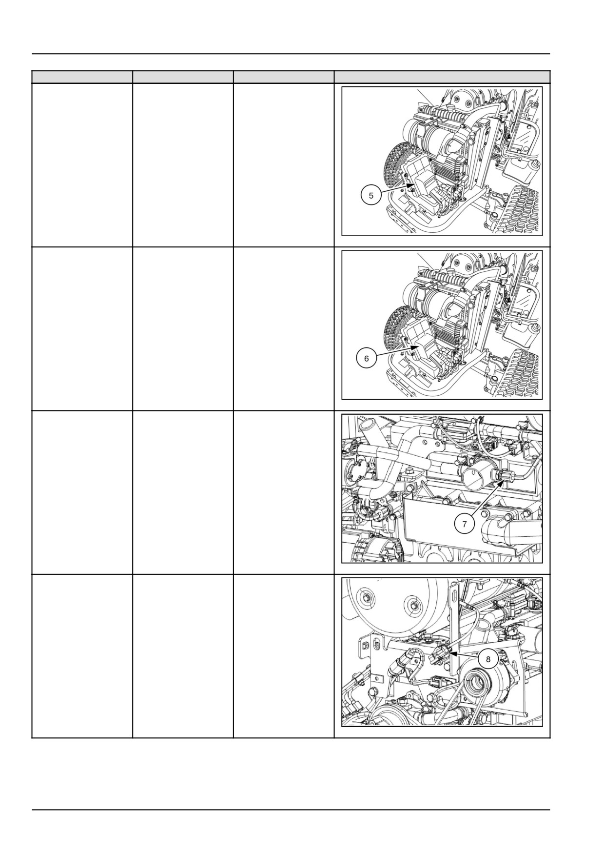
AB09
Engine Control Unit
Normal sensor signal
(ECU)
over 0.25 volts
Barometric pressure
Connector
sensor (5)
connection
Located inside (
Wiring harness for
ECU)
open or shorted
circuit
NHIL13CT01160AC
5
AB10
Engine Control Unit
Normal (ECU)
(ECU)
temperature less
Ambient temperature
than 115 °C (239 °F)
sensor (6)
Located inside (
ECU)
NHIL13CT01160AC
6
AB12
Intake manifold
Normal sensor signal
temperature sensor
0.08 to 4.85 volts
(7)
Connector
connection
Wiring harness for
open or shorted
circuit
NHIL14CT00058AC
7
AB13
Exhaust gas
Normal sensor signal
temperature sensor
164.8 to 4000 ohms
(8)
Connector
connection
Wiring harness for
open or shorted
circuit
NHIL14CT00059AC
8
3-8
3 - CONTROLS AND INSTRUMENTS
Fault code
Possible cause
Check
Location
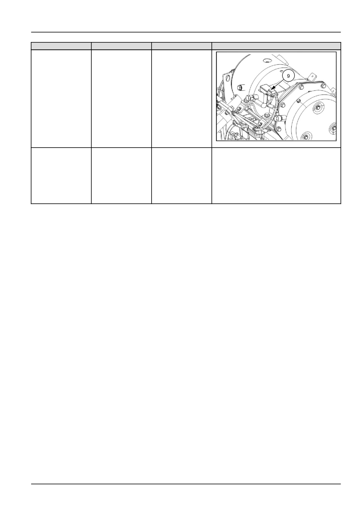
AB14
(DPF) differential
Normal sensor signal
pressure sensor (9)
0.25 to 4.75 volts
Connector
connection
Wiring harness for
open or shorted
circuit
NHIL14CT00060AC
9
AB15
Battery
Normal battery
Positive (+) battery
voltage 6 to 29 volts
cable
(Instant)
Negative (-) battery
Connector
cable
connection
Wiring harness for
open or shorted
circuit
NOTE: Contact your authorized NEW HOLLAND dealer
for fault code analysis.
3-9
3 - CONTROLS AND INSTRUMENTS
Cruise control
WARNING
Loss of control hazard!
To maintain optimum control of the machine,
do not use cruise control at high speeds or
when roading.
Failure to comply could result in death or se-
rious injury.
W1058H
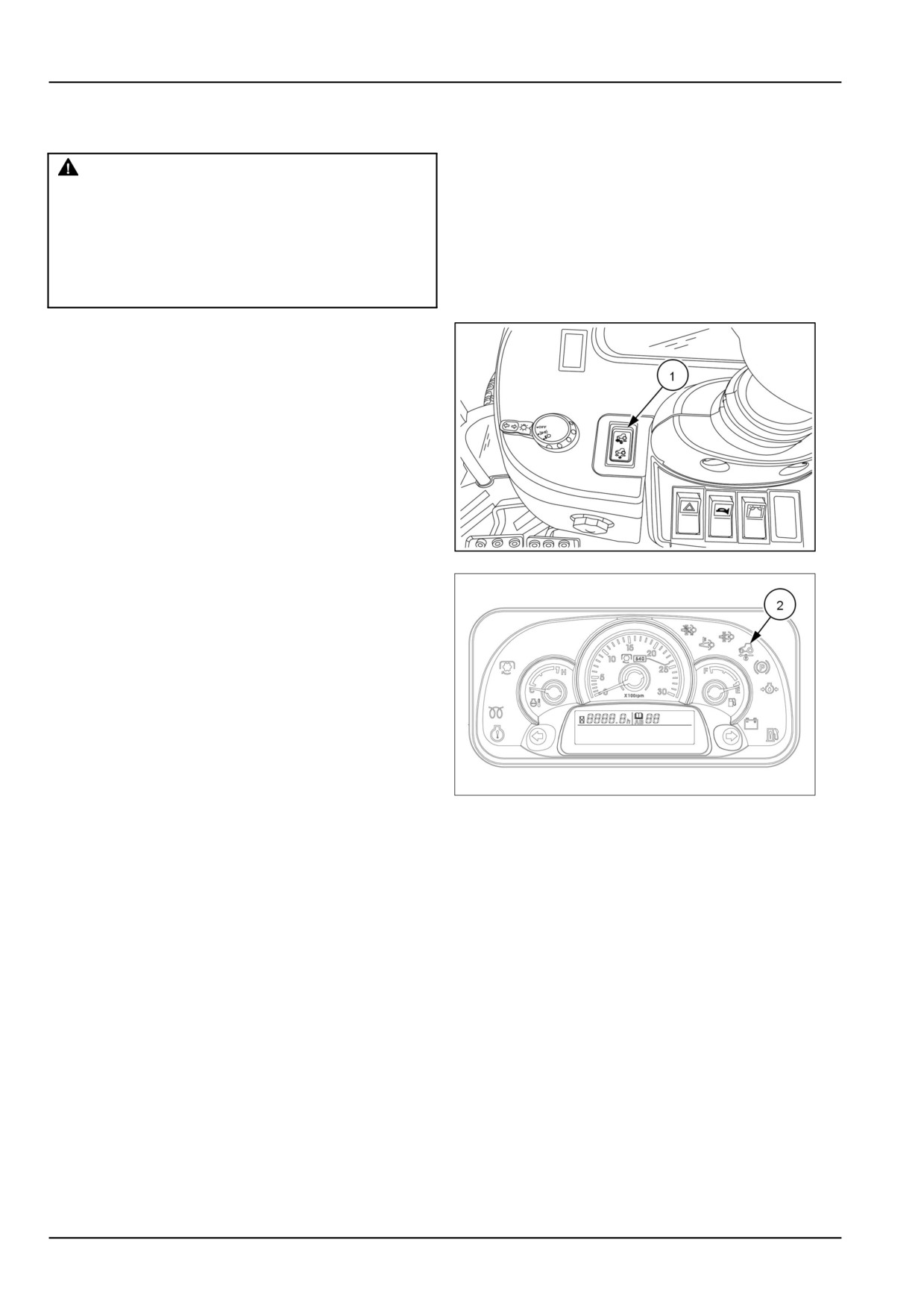
The HST cruise control rocker switch (1) is located on the
left-hand side of the dash panel. It is used to maintain a
constant forward or reverse speed.
NOTE: The rocker switch has three positions, the top half
engages the cruise control, the middle is neutral, and the
bottom half will disengaged the cruise control.
When the desired travel speed is reached, depress the
top half of the cruise control switch. The cruise control
indicator light (2) will illuminate on the instrument panel
indicating the cruise control is engaged.
To disengage the cruise control, depress the bottom half
NHIL13CT01036AA
1
of the switch or depress both brake pedals. The cruise
control indicator light will extinguish, indicating the cruise
control is off.
NHIL14CT00054FA
2
3-10
3 - CONTROLS AND INSTRUMENTS
Transmission shuttle shift lever
NOTICE: Do not attempt to operate the shuttle lever while
the tractor is moving, it may cause damage to the syn-
chromesh gear. The clutch pedal must be depressed and
tractor motion stopped to operate the shuttle lever.
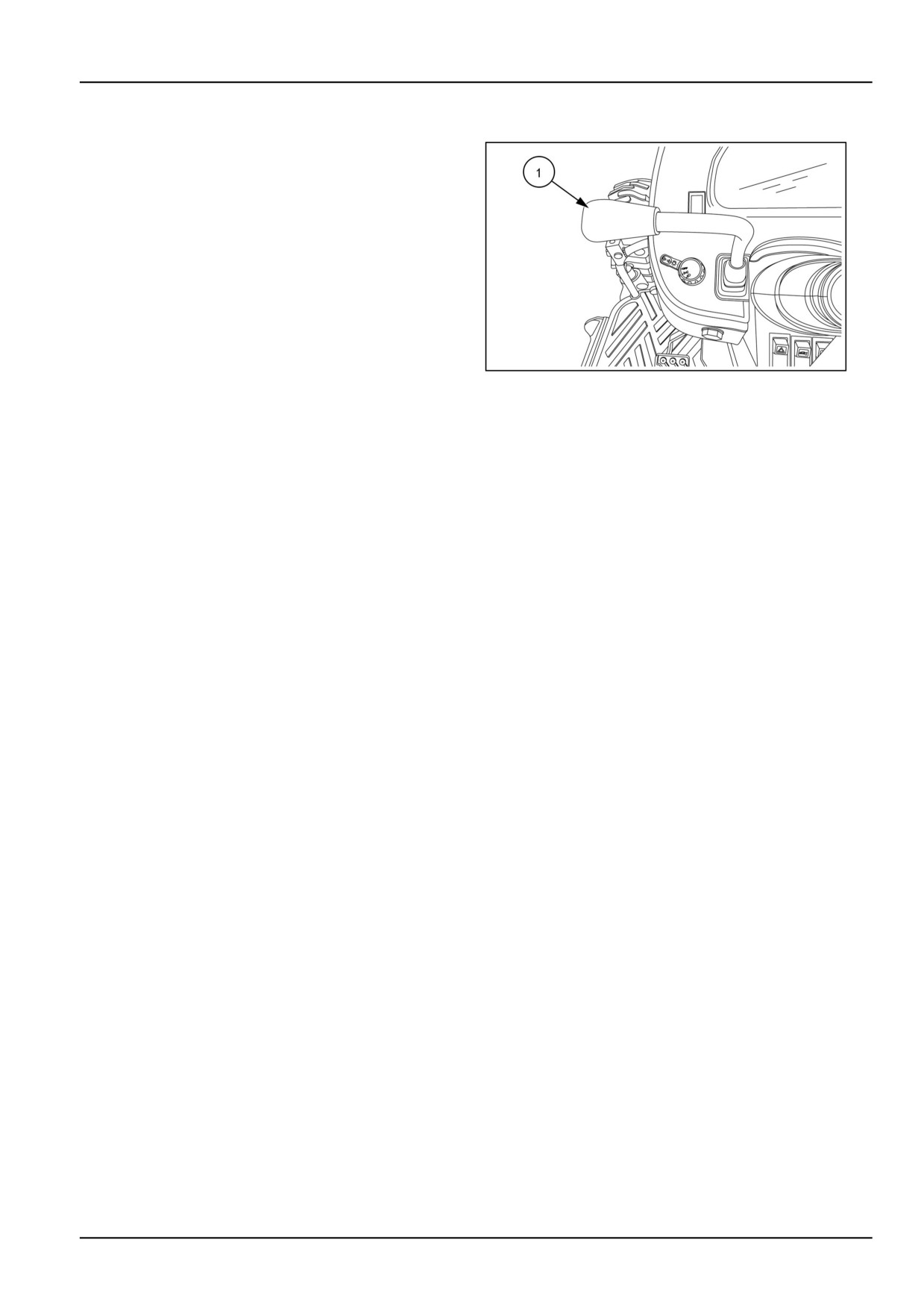
The transmission shuttle shift lever (1) is located on the
left-hand side of the dash panel on gear transmission
model tractors. The shuttle shift lever is used to engage
the transmission into forward or reverse mode while de-
pressing the clutch pedal. Move the lever forward for for-
ward travel and rearward for reverse travel.
NOTE: The shuttle lever must be in the neutral (middle)
position to activate the safety start system, which allows
NHIL13CT01090AA
1
the engine to start.
3-11

3 - CONTROLS AND INSTRUMENTS
Clutch pedal
The foot operated clutch pedal (1) controls the single-
stage clutch and is located on the left-hand side of the
operators platform.
NOTE: The clutch pedal is only found on gear model trac-
tors.
Always depress the clutch pedal fully when engaging or
disengaging the front-wheel drive.
To start the tractor, depress the clutch pedal fully to ensure
a safe start-up.
NHIL13CT01179AA
1
3-12
3 - CONTROLS AND INSTRUMENTS
Brake pedals
WARNING
Loss of control hazard!
Always reduce the traveling speed and use the
steering wheel while you make a turn. When
you operate the machine at high speeds, never
attempt to make sharp turns by using the turn-
ing brake pedals. If you use the individual
brakes at high speeds, the machine could be-
come machine unstable.
Failure to comply could result in death or se-
rious injury.
W1237A
The right brake pedal controls the braking action of the
right rear wheel. The left brake pedal controls the braking
action of the left rear wheel.
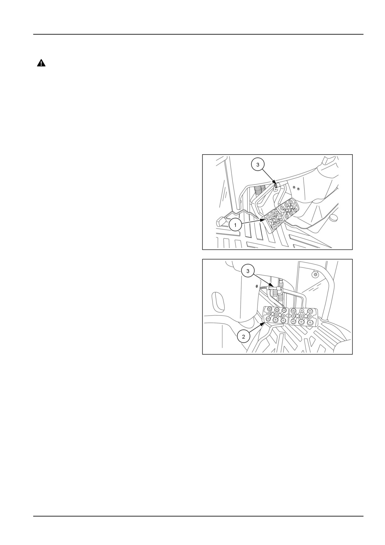
The function of the brake pedals are identical for the HST
and gear model tractors except for the location of the ped-
als. The brake pedals (1) on a HST model tractor are lo-
cated on the left-hand side of the operators platform and
the brake pedals (2) on a gear model tractor are located
on the right-hand side of the operators platform.
Depress both pedals simultaneously to stop the tractor.
To assist in making sharp turns at slow speed, depress
the right or left brake pedal as required.
NHIL13CT01173AA
1
The brake pedal connecting pin (3) is used to secure the
brake pedals together. Lock the pedals together when-
ever the tractor is operated at high speeds or when the
tractor is used on the highway.
NHIL13CT01055AA
2
3-13

3 - CONTROLS AND INSTRUMENTS
Foot throttle pedal
The foot throttle pedal (1) located on the right-hand side
of the operator’s platform of gear transmission model trac-
tors, may be used independent of the hand throttle lever
to control the speed of the tractor.
When using the foot throttle pedal, the hand throttle lever
should be placed in the (low idle) rearward position.
NOTE: It is recommended to use the foot throttle pedal
when driving tractor on public roads.
NHIL13CT01191AA
1
3-14
3 - CONTROLS AND INSTRUMENTS
Hand throttle lever
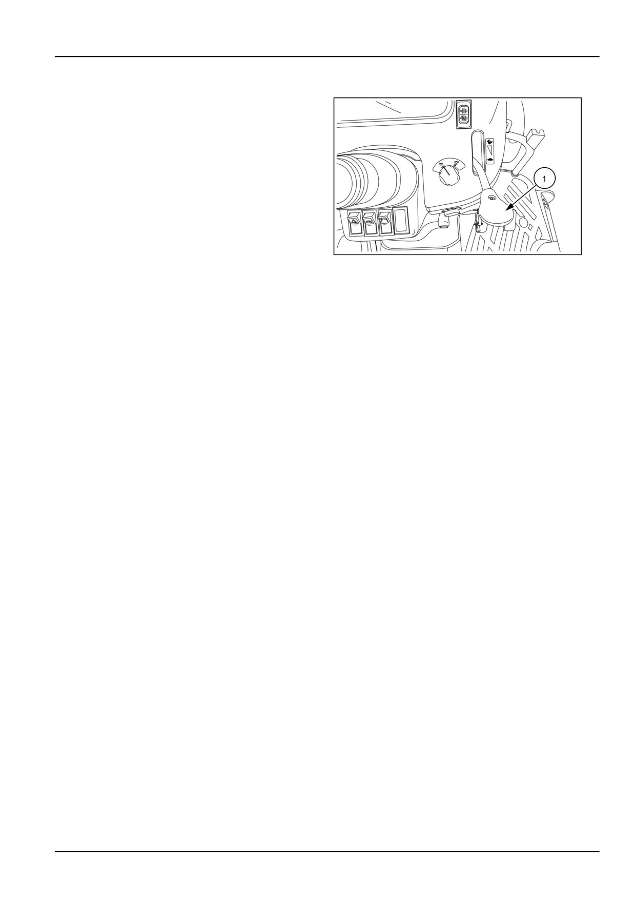
The hand throttle lever (1) is located on the right-hand side
of the dash panel.
Push the lever forward to increase the engine speed and
rearward to decrease the engine speed.
NOTE: The hand throttle lever should only be used during
field operation.
NHIL14CT01049AA
1
3-15

3 - CONTROLS AND INSTRUMENTS
Horn switch
The horn switch (1) is located on the center of the steering
wheel shroud.
To activate the horn, place the key switch in the “ON” po-
sition and push the horn switch down.
NHIL13CT01004AA
1
3-16

3 - CONTROLS AND INSTRUMENTS
Hazard light switch
The hazard light switch (1) is located in the center on the
steering wheel shroud.
To activated the hazard lights, push down on the hazard
light switch (1) with key switch in any position.
NHIL13CT01004AA
1
3-17
3 - CONTROLS AND INSTRUMENTS
Power Take-Off (PTO) switch
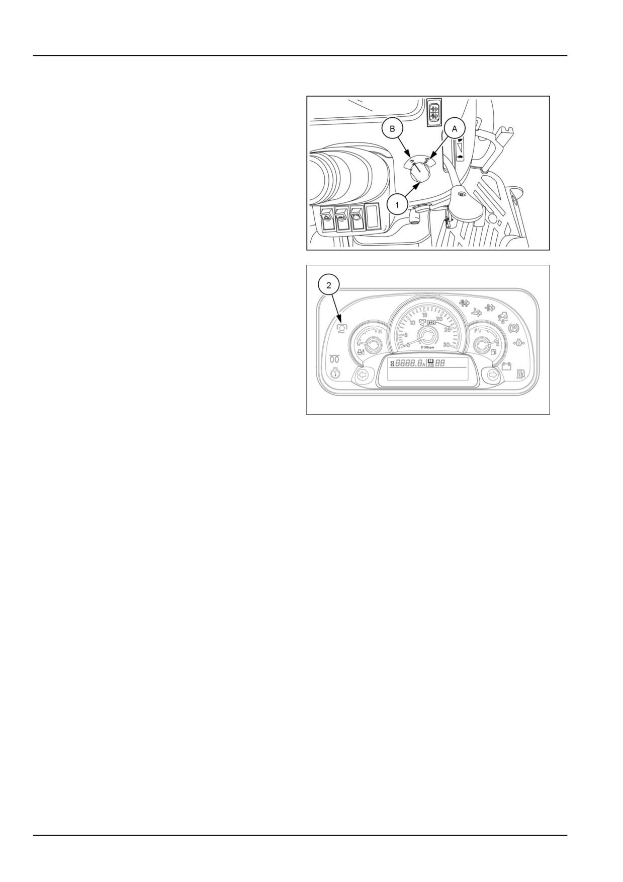
The PTO switch (1) is located on the right-hand side of
the dash panel.
NOTE: To start the engine the PTO switch must be placed
in the "OFF" position
To activate the PTO, push down on the PTO switch and
turn the switch to the "ON" position (A).
When the PTO is engaged the PTO indicator light (2) will
be illuminated on the instrument panel.
To disengage the PTO, push down on the PTO switch and
the switch will automatically return to the "OFF" position
NHIL14CT01049AA
1
(B).
NHIL14CT00054FA
2
3-18
3 - CONTROLS AND INSTRUMENTS
Key switch
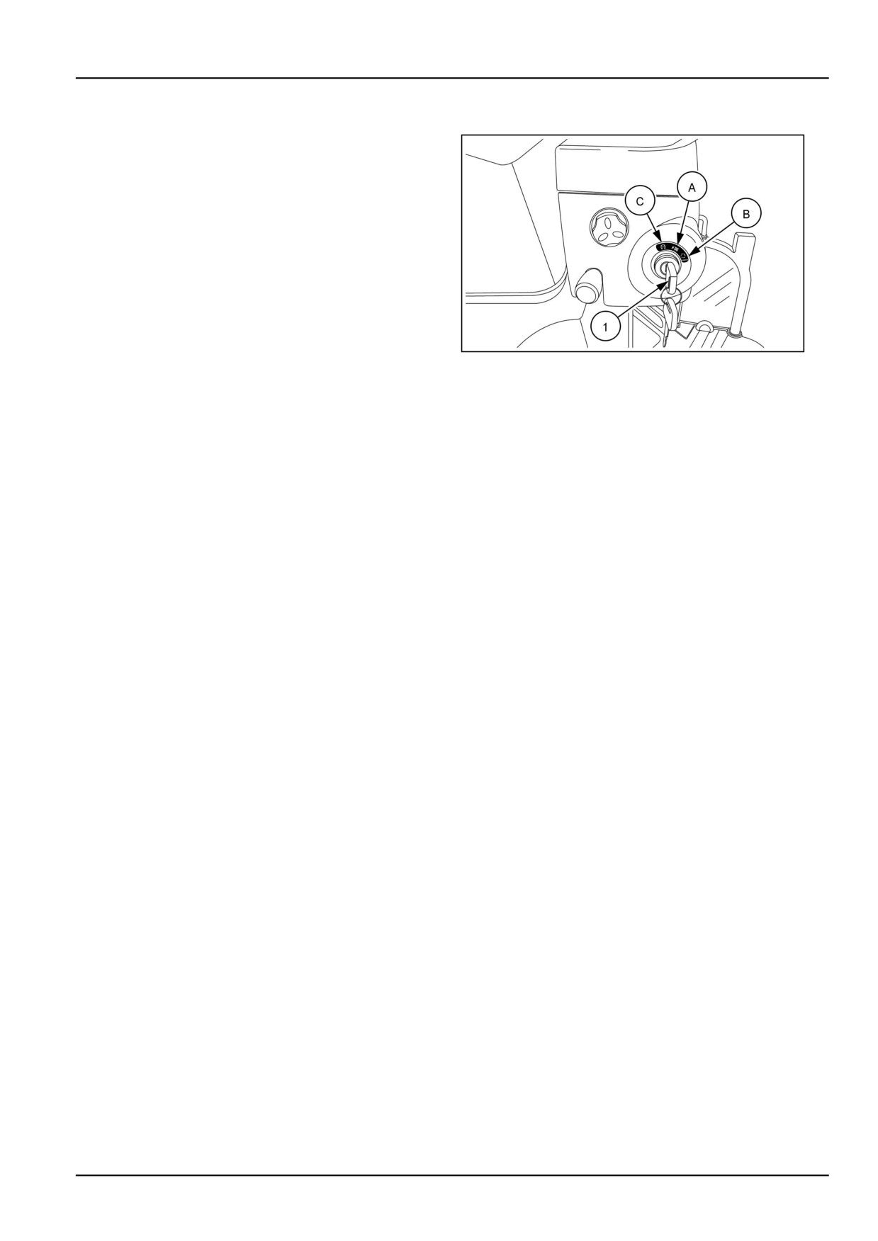
The key switch (1) is located on the right-hand side of the
rear hood panel just below the hand throttle.
• Turning the key to the middle "ON" position (A) acti-
vates the warning lights, instruments, and automatic
engine preheat system.
• The engine starts when the key is turned to the extreme
right "START" position (B). A internal spring returns the
key to the middle "ON" position when released.
• Turning the key to the extreme left "STOP" position (C)
will shut the engine off.
NHIL13CT01006AA
1
3-19
3 - CONTROLS AND INSTRUMENTS
Differential lock pedal
WARNING
Loss of control hazard!
During field operation, use the differential lock
for traction improvement but release for turn-
ing at row end. Do not drive at high speeds or
on roads with the differential lock engaged.
Failure to comply could result in death or se-
rious injury.
W1296A
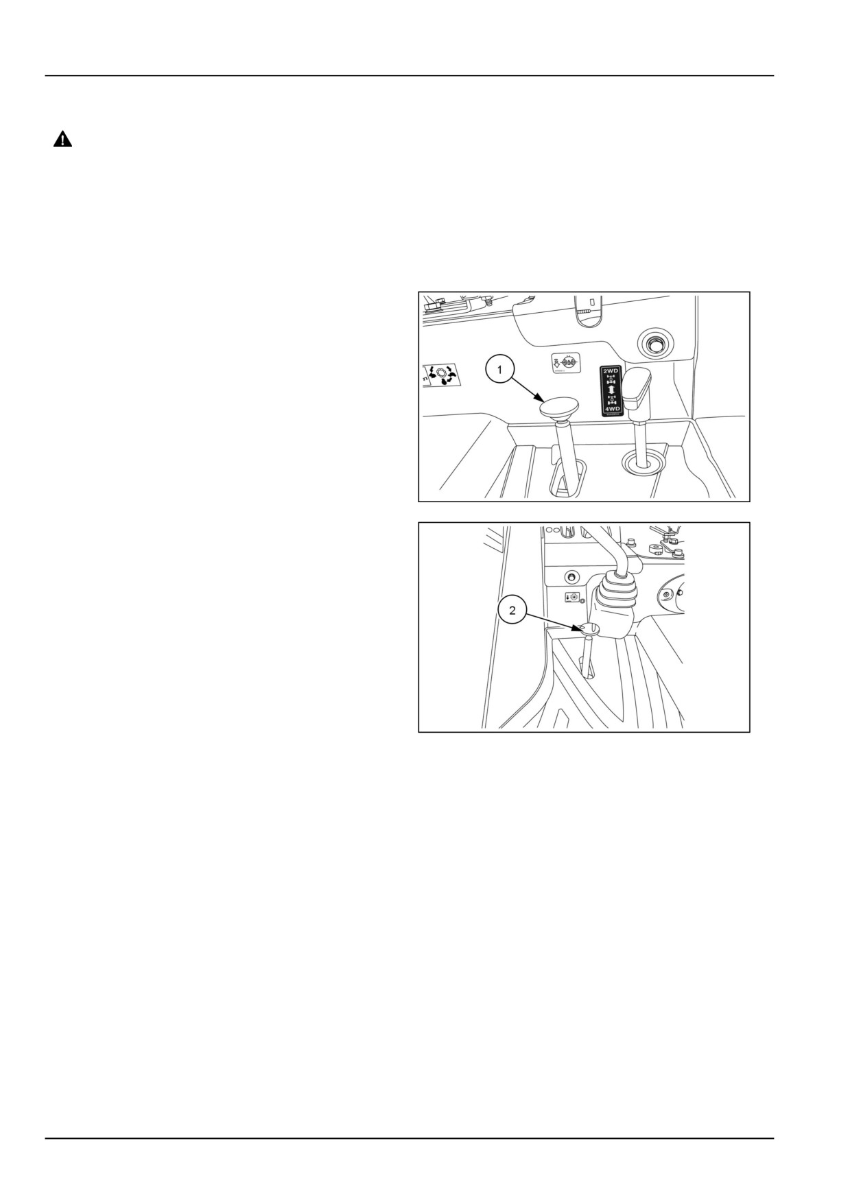
The differential lock pedal is located on the left-hand foot
platform on HST models (1) and on the right-hand foot
platform on gear models (2). The differential lock is used
to obtain additional traction in wet or loose soil.
When the differential lock pedal is depressed, both fi-
nal drive pinion gear shafts are locked together, prevent-
ing one wheel from rotating independently of the other.
Whenever one wheel begins to slip in wet or loose soil,
use the lock to obtain additional traction from the oppo-
site wheel.
To operate the differential lock, depress and hold the
pedal down until the lock is positively engaged. It is best
NHIL13CT01361AA
1
to engage the lock while the wheels are turning slowly to
minimize shock loads to the driveline. If a wheel spins at
high speed, such as on ice, reduce engine speed to idle
before engaging the lock or damage may result. Release
the pedal to disengage the differential lock.
NOTE: In some instances, the lock may remain engaged
after the pedal is released. This can occur if one rear
wheel is turning at a faster speed than the other. The lock
can be disengaged in one of two ways if this occurs:
• Decrease the drawbar pull by raising or disengaging the
implement so that neither wheel tends to slip.
• Depress the clutch pedal and rapidly apply and release
NHIL13CT01180AA
2
a light braking load to the wheel with less traction.
3-20

3 - CONTROLS AND INSTRUMENTS
Hydrostatic transmision (HST) foot pedals
The ground speed of tractors equipped with a hydrostatic
transmission is continuously variable, from zero to full
rated speed in each range. Speed is controlled by the
HST forward (1) and reverse (2) pedals located on the
right-hand foot platform.
For forward travel:
• Depress the forward pedal (1) until the desired ground
speed is reached.
For reverse travel:
• Depress the reverser pedal (2) until the desired ground
speed is reached.
NHIL13CT01172AA
1
NOTE: Pedal will return to the neutral position when the
operator’s foot is removed from the pedal, unless the HST
cruise control switch is placed in the "ON" position.
3-21
3 - CONTROLS AND INSTRUMENTS
Tilt steering lever
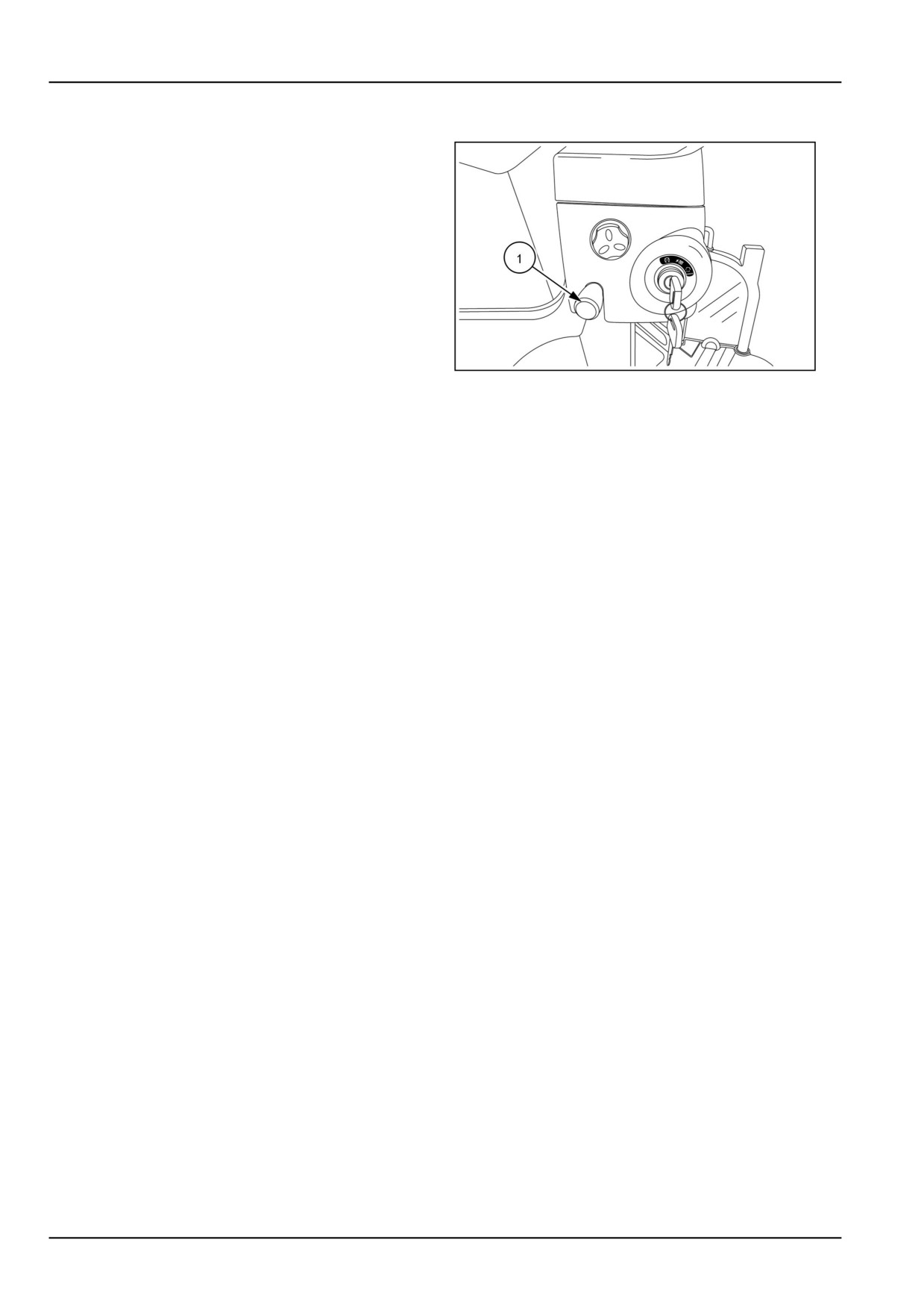
The tilt steering lever (1) is located on the right-hand side
of the steering column shroud.
The tilt steering lever is used to adjust the steering wheel
position.
To adjust position of steering wheel:
1. Push down on tilt steering lever (1) and position steer-
ing wheel as needed.
2. Pull up on tilt steering lever to lock steering wheel in
place
NHIL13CT01006AA
1
3-22
3 - CONTROLS AND INSTRUMENTS
Multifunction light switch
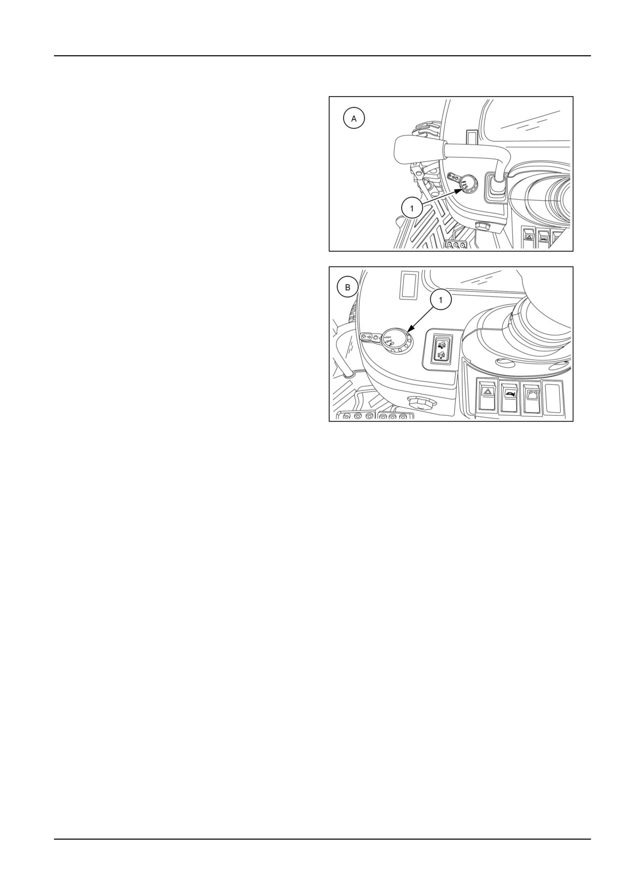
The multifunction light switch (1) is located on the left-
hand side of the dash panel and is used to control the
front road lights, taillights and turn signals.
NHIL13CT01090AA
1
NHIL13CT01036AA
2
(A) GEAR MODEL
(B) HST MODEL
3-23
3 - CONTROLS AND INSTRUMENTS
DPF switch
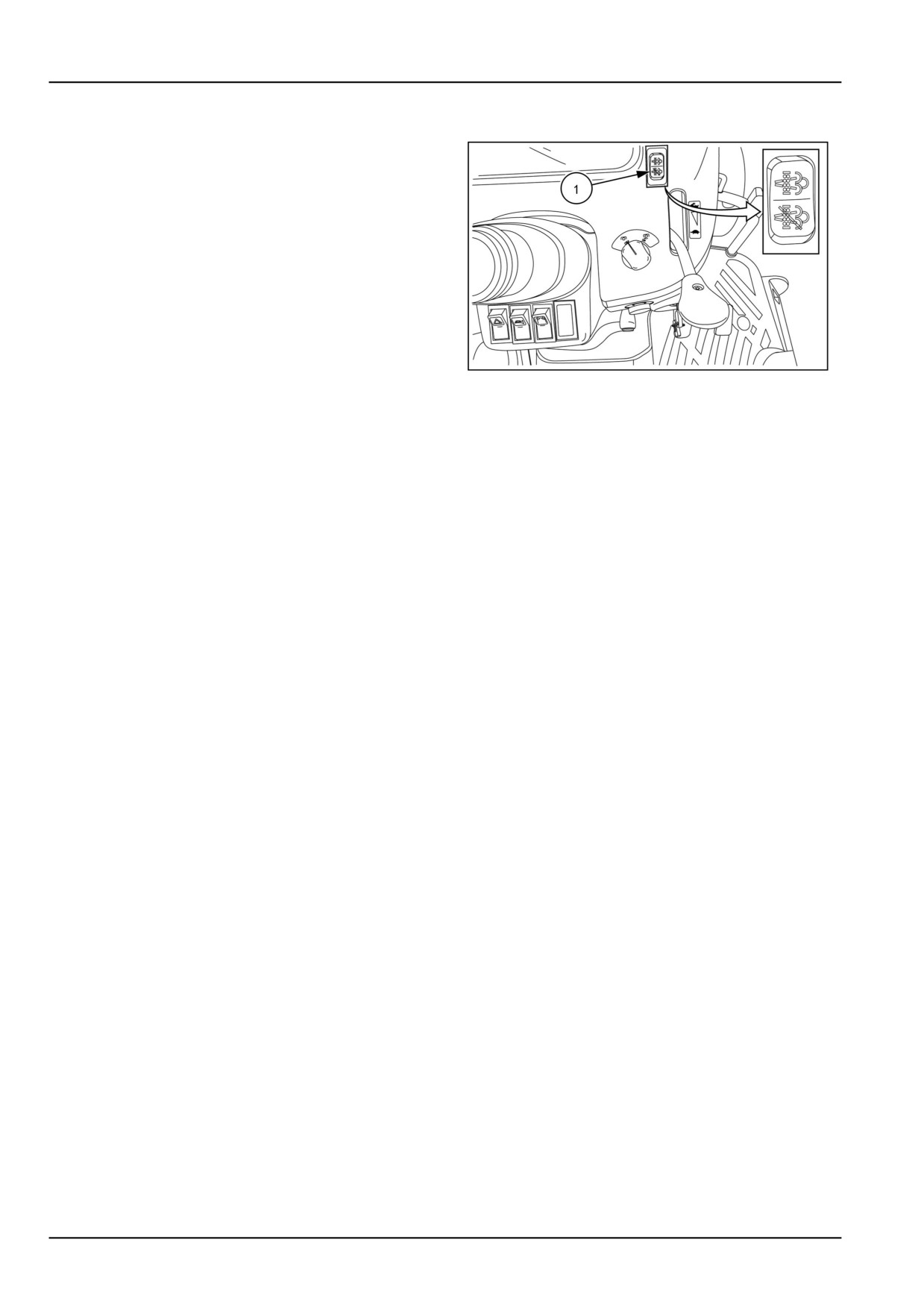
The (DPF) switch (1) located on the right-hand side of
the dash, is used to delay or stop the regeneration of the
(DPF) emission system. See 4-2 for more detail explana-
tion of operation of this switch.
NHIL14CT00050AA
1
3-24
3 - CONTROLS AND INSTRUMENTS
LEFT-HAND SIDE CONTROLS
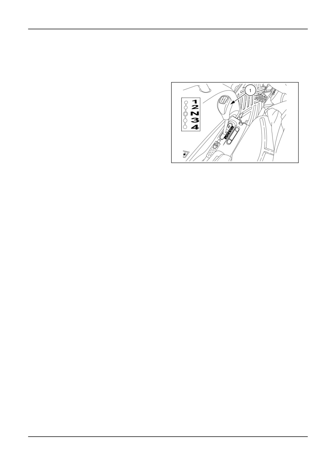
Transmission range lever
Gear model
The transmission range selector lever (1) is located on the
left-hand control pod. There are four speed ranges, 1, 2,
3, and 4. There is a neutral position between the 2nd and
3rd range positions.
NOTICE: Never attempt to engage or disengage the
range lever when the tractor is in motion.
NHIL13CT01354AA
1
3-25
3 - CONTROLS AND INSTRUMENTS
Park brake
WARNING
Unexpected movement!
Always engage the parking brake and switch
off the engine before exiting the machine.
Failure to comply could result in death or se-
rious injury.
W0209A
NOTICE: Ensure the park brake is fully disengaged before
driving the tractor.
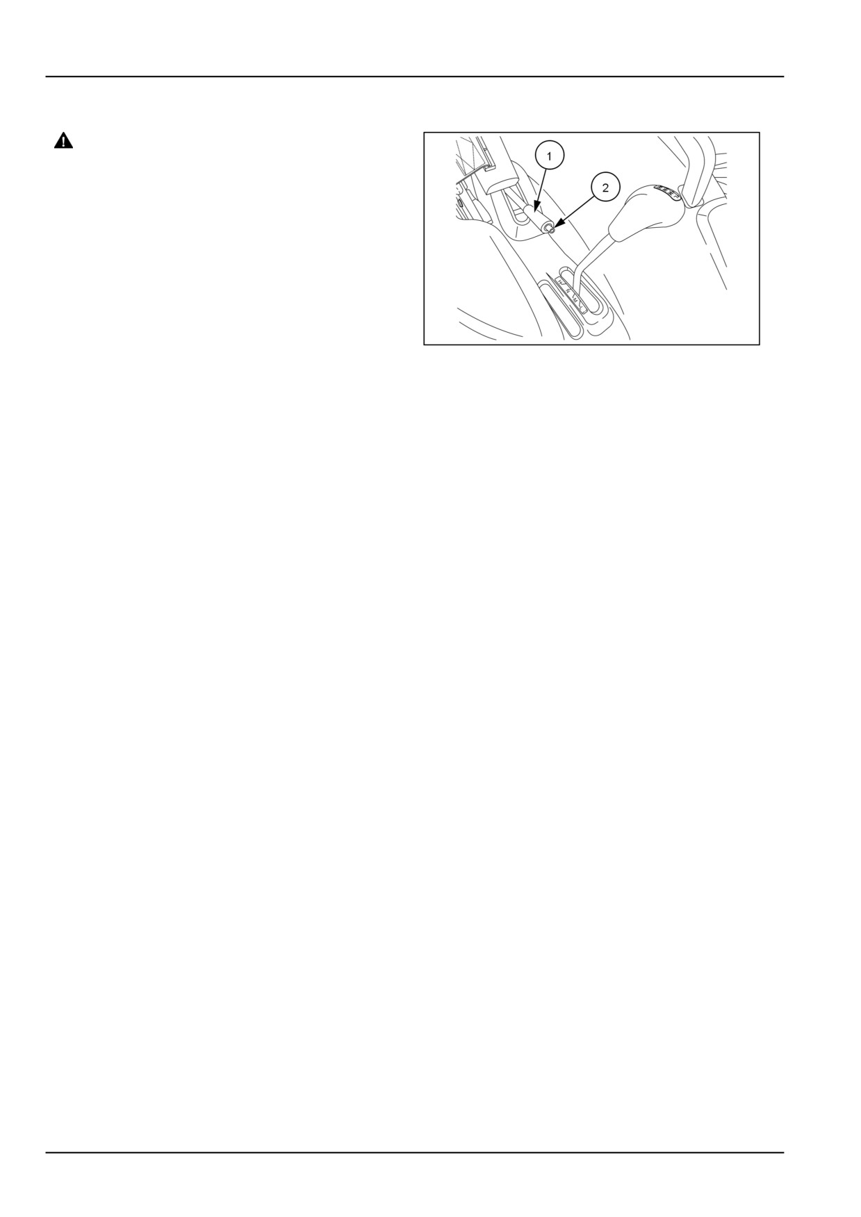
The park brake lever (1) is located on the left-hand side
of the operators platform. The park brake is used to apply
the rear axle brakes to prevent the tractor from moving
NHIL13CT01174AA
1
while parked.
To engage the park brake, lock the pedals together and
pull the park brake lever up while pressing the brake ped-
als down.
NOTE: Always engage the park brake when getting off
the tractor. If the brakes are not engaged or the operator
leaves the seat without engaging the park brake a alarm
will sound. The alarm will continue to sound for approxi-
mately ten seconds or until the park brake is engaged.
To disengage the park brake, press the brake pedals
down, push button (2) in the end of the park brake lever
to release lever and push the lever (1) downward.
3-26
3 - CONTROLS AND INSTRUMENTS
Front-wheel drive lever
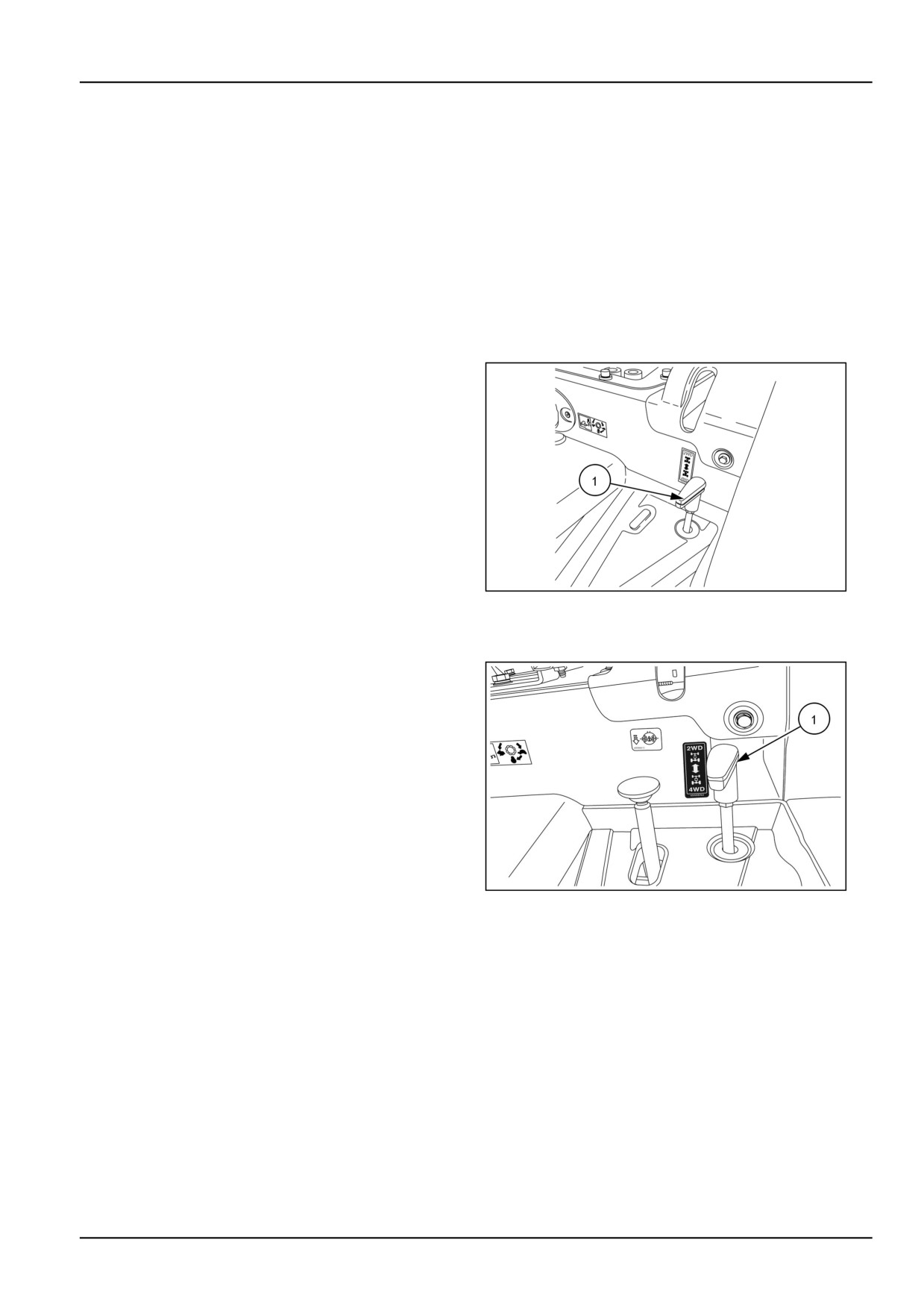
The front-wheel drive (FWD) is controlled by a handle.
The handle is located on the left-hand side of operator’s
platform.
NOTE: Use front-wheel drive when additional traction is
required while operating on loose soil, in wet, slippery con-
ditions, or on slopes. For normal operation on firm soil,
level hard surfaces, or when operating the unit at high
speeds, disengage the front-wheel drive to maximize tire
and driveline life and to economize on fuel.
Gear model
To engage the front-wheel drive on gear model tractors,
stop the tractor completely, depress the clutch pedal and
push the handle (1) completely downwards. To disengage
the front-wheel drive, stop the tractor completely and pull
the handle upwards.
NHIL13CT01175AA
1
HST model
To engage the front-wheel drive on HST model tractors,
stop the tractor completely and push the handle (1) com-
pletely downwards. To disengage the front-wheel drive,
stop the tractor completely and pull the handle upwards.
NHIL13CT01361AA
2
3-27
3 - CONTROLS AND INSTRUMENTS
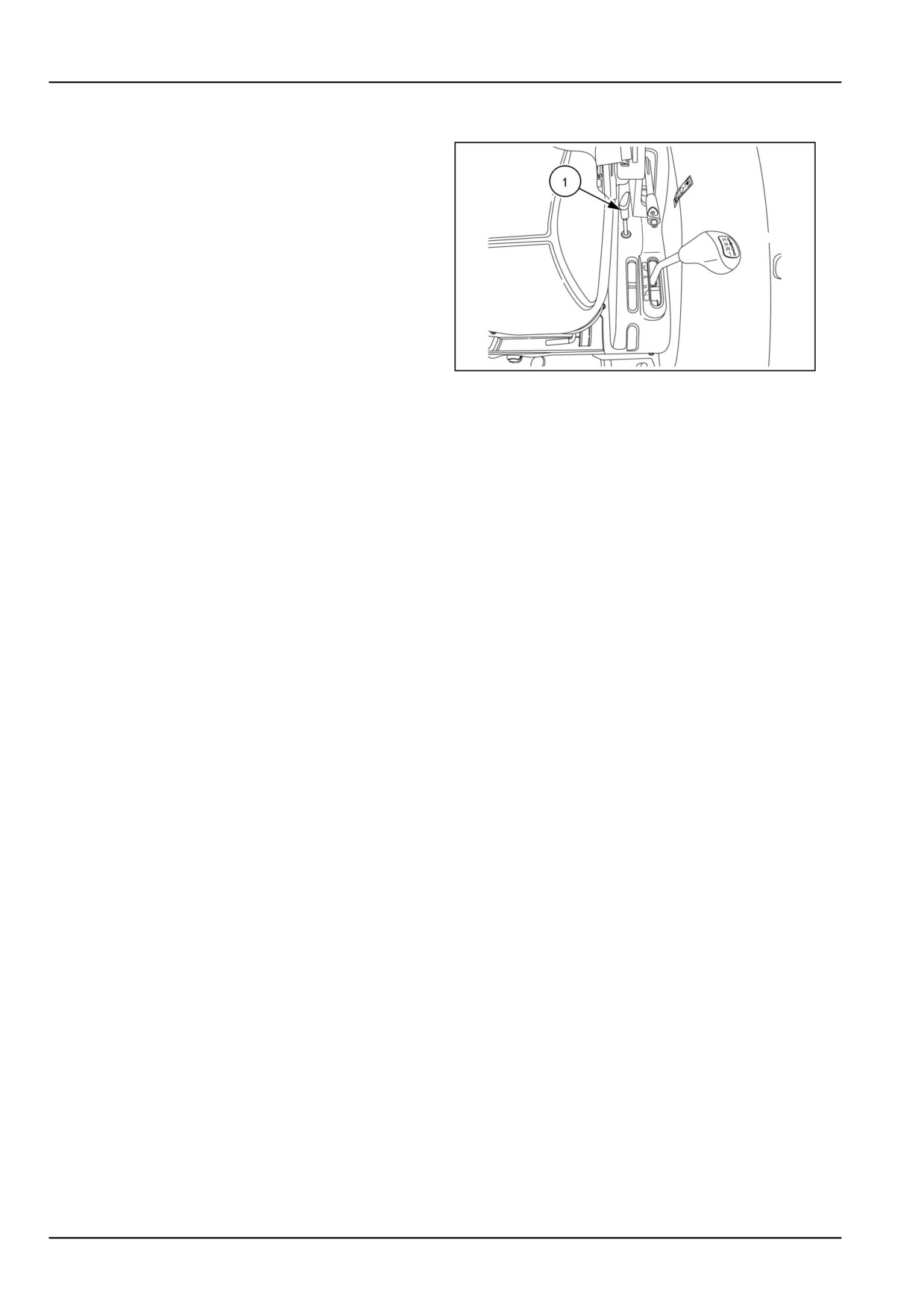
Mid Power Take Off (PTO) lever - optional
The mid PTO lever (1) is located on the left-hand control
pod.
NHIL13CT01248AA
1
3-28