New Holland Boomer 41, Boomer 47 Compact Tractor. OPERATOR’S MANUAL (2014) - page 3
3 - CONTROLS AND INSTRUMENTS
RIGHT-HAND SIDE CONTROLS
Hydraulic power lift (HPL)
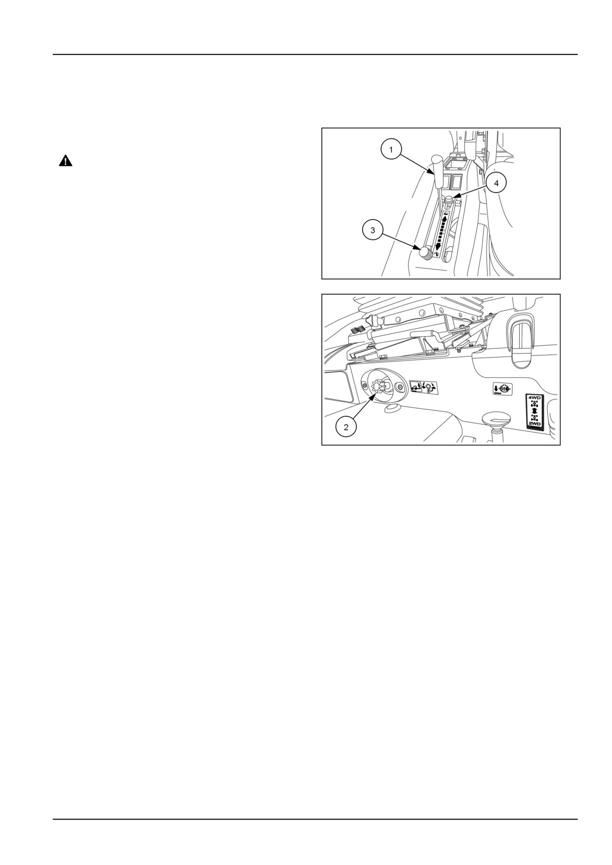
The HPL lever (1) is located on the right-hand control pod.
The lever controls the position of the two lift arms.
DANGER
Crushing hazard!
Make sure area is clear of all persons before
lowering equipment.
Failure to comply will result in death or serious
injury.
D0016A
To lower the lift arms, first make sure the drop rate con-
trol valve (2) is open, then move the HPL lever forward. To
raise the lift arms, move the lever rearward. An adjustable
NHIL13CT01178AA
1
lower stop (3) is located in this quadrant for returning the
lever to a preset lowering position of the hitch. An ad-
justable upper HPL control lever height stop (4) prevents
the control lever from exceeding the lift limit and causing
the tractor hydraulic system to go over the relief valve set-
ting.
The hydraulic lift system provides accurate, smooth, and
instant hydraulic power for raising a variety of compatible
equipment whenever the engine is running. The system's
position control feature maintains the selected height or
depth of three-point linkage equipment in relation to the
tractor. When the hydraulic lift control lever is moved to a
higher or lower setting in the quadrant, the system repo-
sitions the equipment to a higher or lower position and
NHIL13CT01026AA
2
maintains the selected position.
Position control
Position control provides easy, accurate control of the
three-point linkage equipment which operated above the
ground, such as sprayers, rakes, mowers etc. It also pro-
vides uniform depth when using a blade or similar equip-
ment on ground level.
When operating in position control, there is a definite re-
lationship between the position of the control lever in the
quadrant and the position of the equipment. The lever
must be moved to change the position of the equipment
relative to the tractor. The system will automatically main-
tain the equipment in the selected position.
3-29

3 - CONTROLS AND INSTRUMENTS
Draft control - optional
The optional draft control lever (1) will be located in the slot
on the right-hand control pod, next to the position control
lever (2).
The draft control lever sets the desired depth of the at-
tached implement. Draft control is best when using im-
plements that operate in the ground, such as plows, har-
rows, or cultivators. The draft loading on the implement
increases and decreases as the working depth or the soil
resistance changes.
To set the draft control, move the position control lever (2)
to its full forward position. Then set the implement draft
depth lower by moving draft control lever forward, or set
93103864
1
it higher by moving lever rearward.
Implement depth will be promotional to draft, depending
on the soil conditions. With draft control, the lift keeps the
tractive effort steady automatically.
You can limit the range manual draft lever operation by
moving and tightening the stop (3).
Combined draft and position control
You can use draft and position control together to oper-
ate in draft control but prevent the implement from sink-
ing excessively when soil conditions change. First set the
draft control lever with the position control lever fully for-
ward. Then move the position control lever back until the
lift arms start to rise. The position control lever sets the
lowered position of the hydraulic lift.
Float operation
Move the draft control lever and position control lever fully
forward. The three-point linkage will now be free to "float"
or follow the ground contour, a feature useful for scraper
blades, etc.
3-30
3 - CONTROLS AND INSTRUMENTS
Rear remote control valve(s) - optional
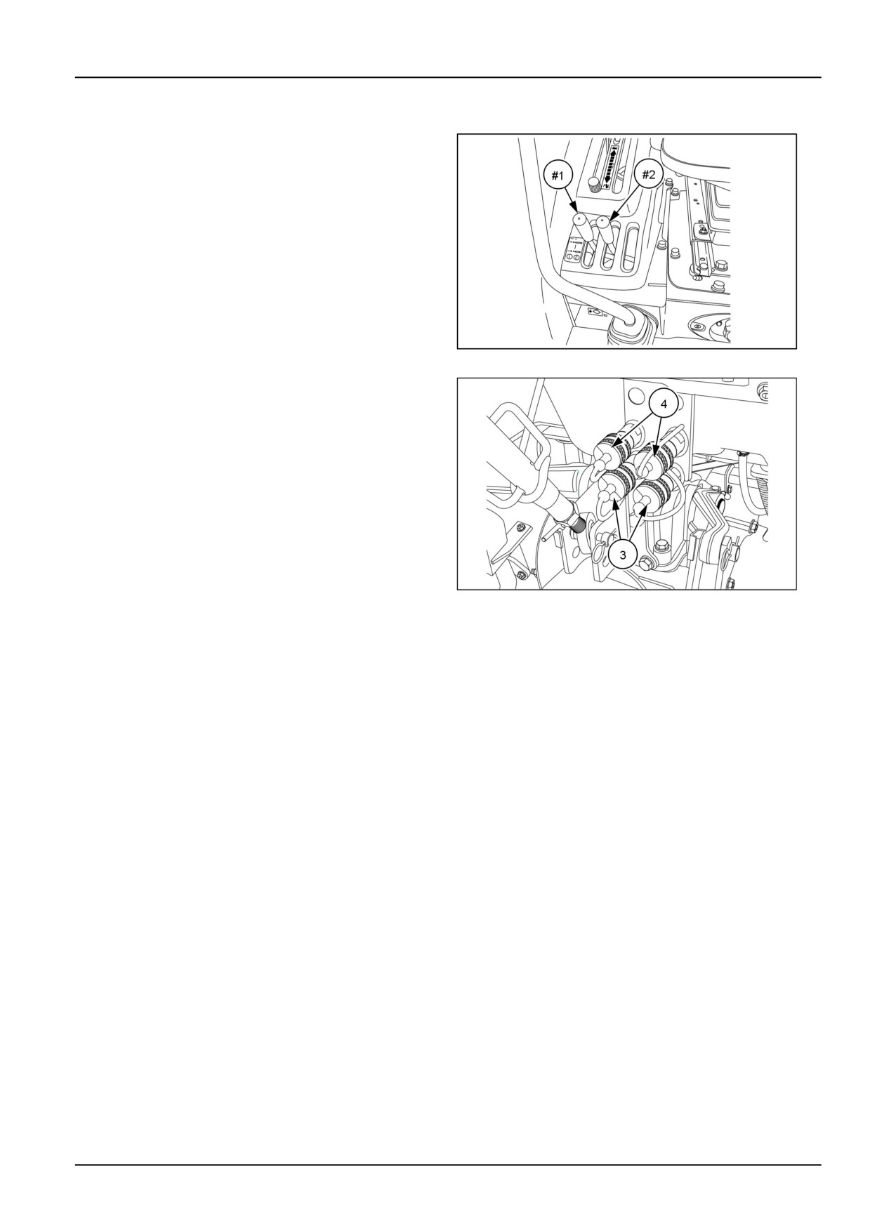
Your tractor can be equipped with one or two optional rear
remote valves. The control lever(s) (#1) and (#2) is/are
located in front of the right-hand control pod.
NOTE: Rear remote valve kits are configured in either
single spool or two spool. Once a single spool valve is
installed, you CANNOT stack another single spool valve.
You must purchase the two spool valve kit.
To operate the single or two spool valve, pull the selected
control lever rearward to extend the cylinder and push the
control lever forward to retract the cylinder. Release the
control lever to stop the cylinder in any position before it is
fully extended. The lever automatically returns to neutral.
NHIL13CT01177AA
1
The #1 (Green) set of couplers (#1) is located on bottom
and the #2 (Blue) set of couplers (#2) is located on top.
The rear remote valves come standard with 12.7 mm
(0.5 in) female quick couplers .
93100915
2
3-31
3 - CONTROLS AND INSTRUMENTS
Mid mount two spool control valve
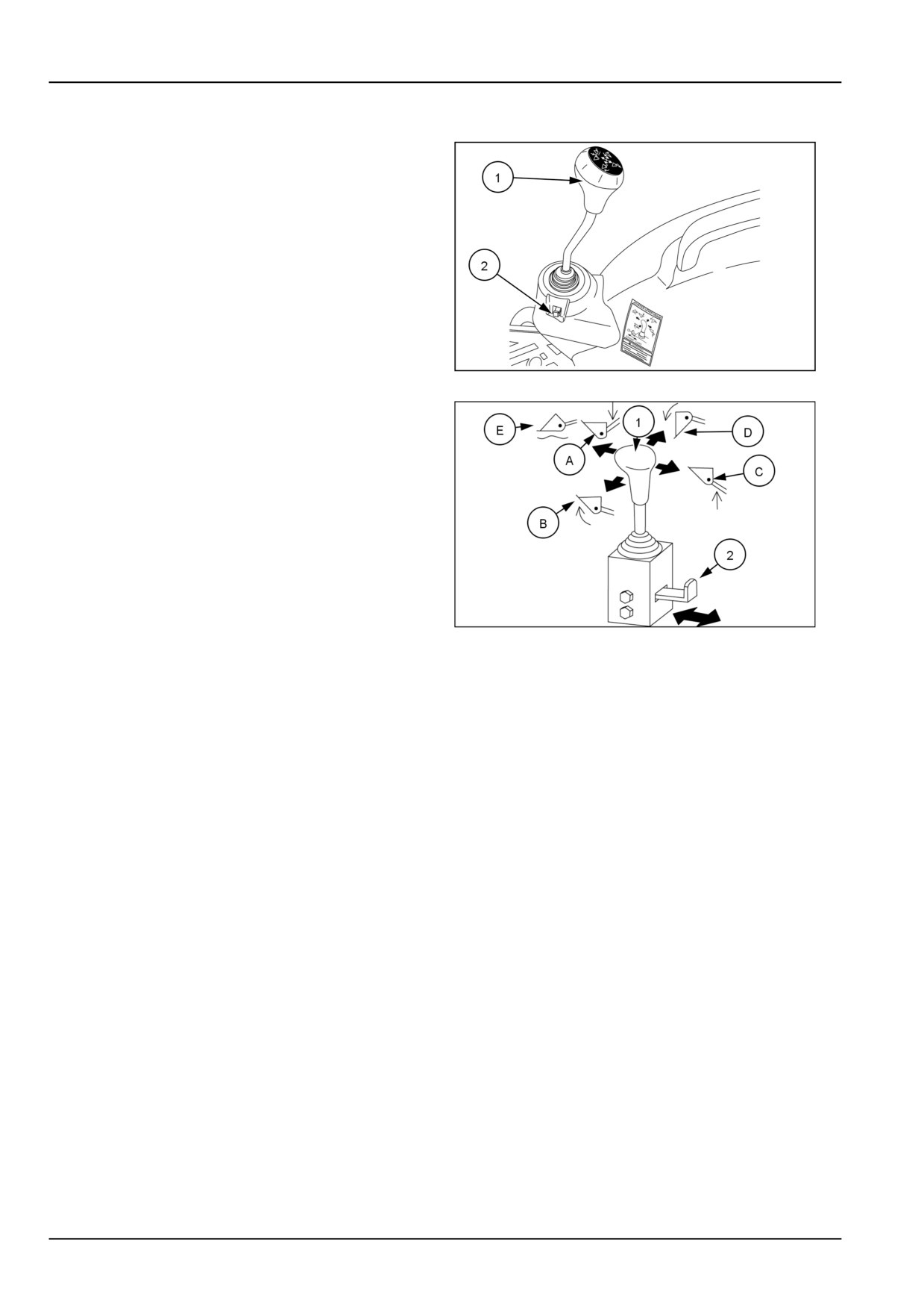
The mid mount two spool control valve (1) is mounted to
the front of the right-hand fender. This control valve is
used mainly for front end loader operation, but may also
be used to operate other front mounted implements.
The control valve is equipped with a linkage lockout (2)
that locks the control valve handle in the neutral position
and does not allow the valve to operate.
NHIL13CT01193AA
1
To operate the control valve, move the control lever (1) in
any of the four directions.
Release the control lever to stop the cylinder in any posi-
tion, the lever automatically returns to neutral.
• Move the control lever forward to lower the loader/re-
tract cylinder (A).
• Move the control lever to the left to curl the bucket/re-
tract cylinder (B).
• Move the control lever rearward to raise the loader/ex-
tend cylinder (C).
• Move the control lever to the right to dump bucket/ex-
93100858
2
tend cylinder (D).
• Move the control lever fully forward to "FLOAT" position
(E) which allows the loader boom lift cylinders to extend
or retract freely. This valve position will allow the loader
to follow the ground contour during operation.
NOTE: Do not use the "FLOAT" position (E) if the loader
bucket is raised off the ground. .
NOTE: Push the lockout tab (2) inwards to lock the valve
control lever when the two-spool control valve is not used.
NOTE: If you move the control lever diagonally the loader
and bucket will operate at the same time.
3-32
3 - CONTROLS AND INSTRUMENTS
Hydraulic hose connection
WARNING
Crushing hazard!
Before disconnecting the cylinders or equip-
ment, make sure you adequately support and
secure the equipment or implement.
Failure to comply could result in death or se-
rious injury.
W0243A
WARNING
Escaping fluid!
Remote couplers must be properly mounted
and securely fastened to the machine mount-
ing bracket for proper functioning of the safety
disconnect feature.
Failure to comply could result in death or se-
rious injury.
W0131A
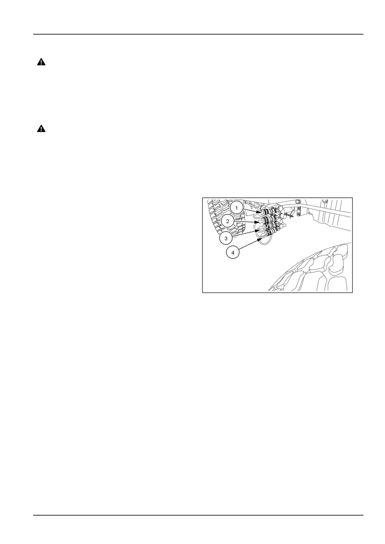
When connecting hydraulic hoses , follow the instructions
listed below.
• Loader down/retract cylinder, yellow coupler (1).
• Loader up/extend cylinder, green coupler (2).
• Bucket curl/retract cylinder, red coupler (3).
• Bucket dump/extend cylinder, blue coupler (4).
NHIL13CT00921AA
3
3-33
3 - CONTROLS AND INSTRUMENTS
Transmission main shift lever
Gear model
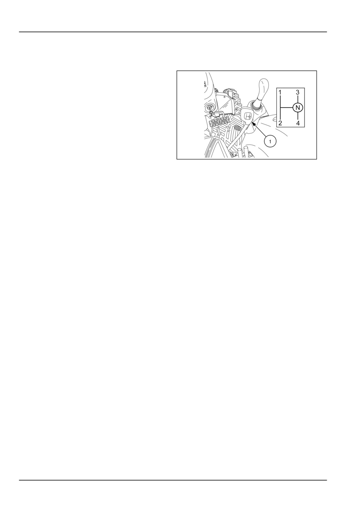
The transmission main gear shift lever (1) is located on
the right-hand side of the operators platform, and is used
to select any one of the four forward or reverse gears.
With the combination of the shuttle shift, main shift, and
range selector lever offer the operator a combination of
twelve forward and twelve reverse gears.
The transmission shift lever operates in a H-pattern. To
change gears while in a selected range, depress the
clutch pedal and shift the main gear shift lever into the
desired gear. The tractor does not have to be stopped
because the main shift gears are synchronized.
NHIL13CT01355AA
1
3-34
3 - CONTROLS AND INSTRUMENTS
Transmission range lever
HST model
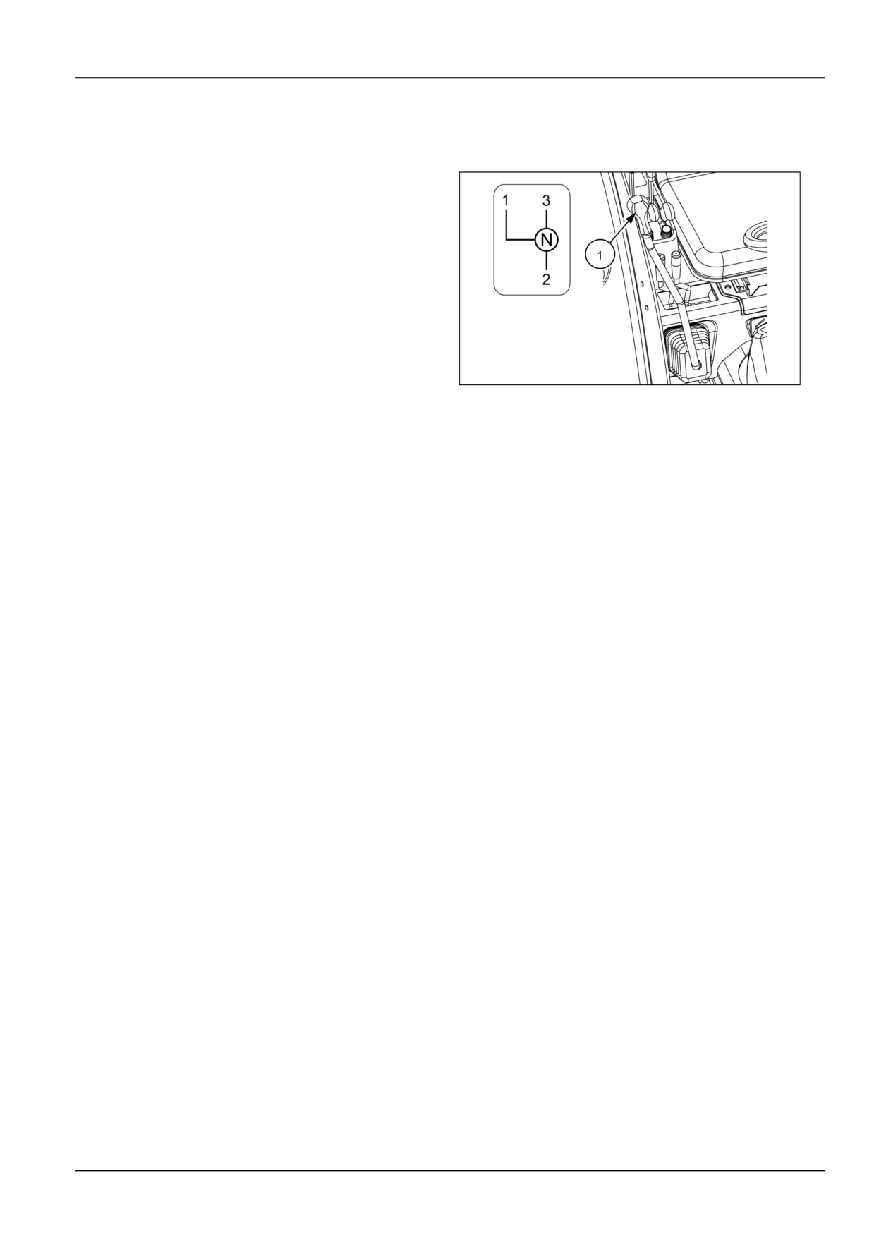
The transmission range shift lever (1) is located on the
right-hand side of the operator’s platform. The transmis-
sion range shift lever operates in a H-pattern. HST model
tractors have a three range speeds and one neutral posi-
tion.
NOTE: The shift pattern is shown as sitting in the opera-
tor’s seat.
NOTICE: Never attempt to engage or disengage the
range shift lever when the tractor is in motion.
93101616A
1
3-35
3 - CONTROLS AND INSTRUMENTS
EXTERIOR CONTROLS
Hood release latch
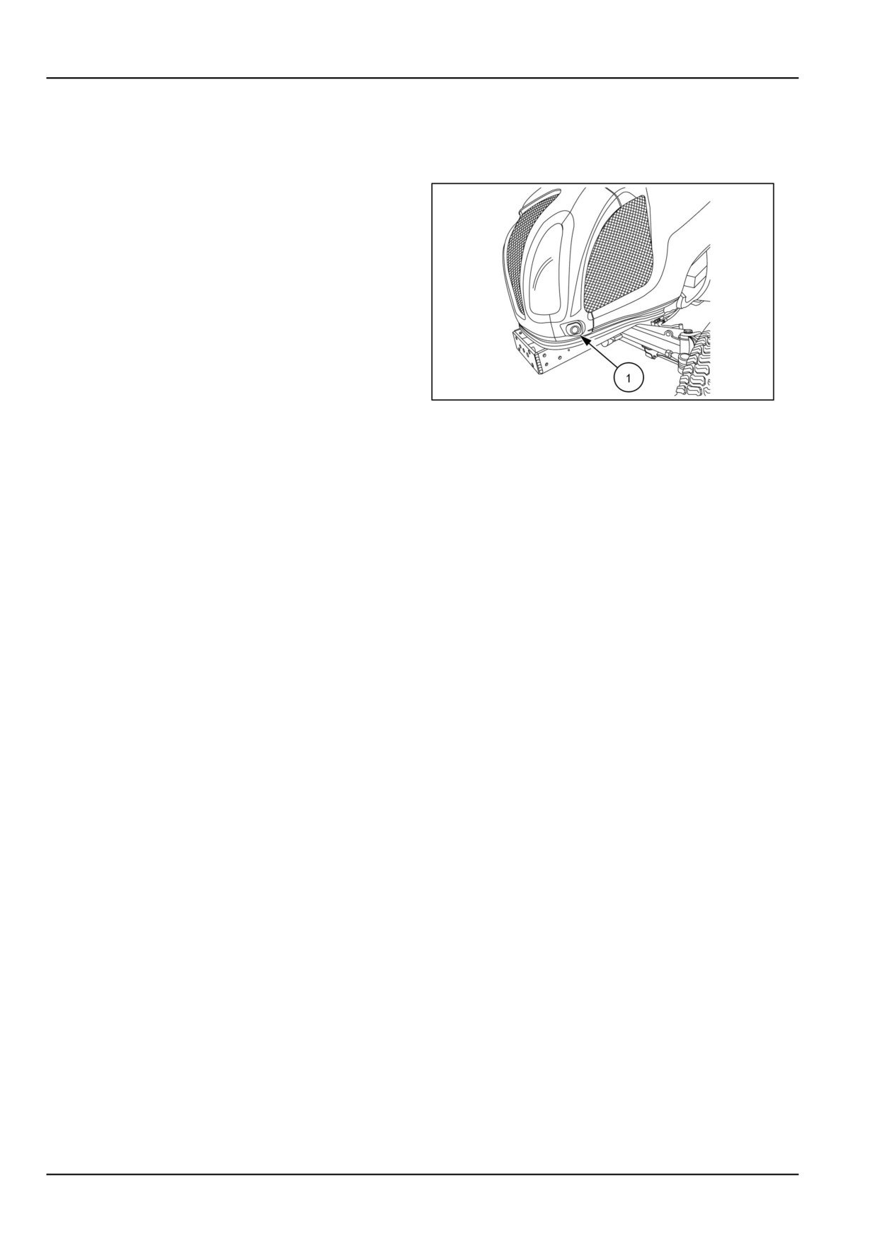
The latch release button is located on the left-hand side
of the tractor hood.
1. To raise the hood, push the latch release button (1)
inward and lift the hood to its fully raised position. A
gas shock holds the hood in the fully raised position.
2. To close, lower the hood until it is retained by the latch
mechanism.
NOTE: Keep latch mechanism free of dirt and debris so
latch assembly will operate properly.
NHIL13CT01012AA
1
3-36
4 - OPERATING INSTRUCTIONS
4 - OPERATING INSTRUCTIONS###_4_###
COMMISSIONING THE UNIT
Engine break-in procedure
Your tractor will provide long and dependable service if
given proper care during the first 50-hour break-in period.
During the first 50 hours of operation:
1. Avoid "lugging" the engine. Operating in too high a
gear under heavy load may cause engine lugging,
which is indicated when the engine will not respond
to a throttle increase.
2. Use the lower gear ratios when pulling heavy loads
and avoid continuous operation at constant engine
speeds. You will save fuel and minimize engine wear
by selecting the correct gear ratio for a particular op-
eration. Operating the tractor in low gear with a light
load and high engine speed wastes fuel.
3. Avoid prolonged operation at either high or low engine
speeds without a load on the engine.
4. Check the instruments frequently and keep the ra-
diator and oil reservoirs filled to recommended lev-
els. Daily checks include the engine oil level, radiator
coolant, and air cleaner.
5. After the first 50 hours of use, be sure to perform the
maintenance items listed in the maintenance sched-
ule.
4-1
4 - OPERATING INSTRUCTIONS
Diesel Particulate Filter (DPF) regeneration
CAUTION
WARNING
Burn hazard!
Fire hazard!
During the Diesel Particulate Filter (DPF) re-
During the Diesel Particulate Filter
(DPF)
generation process the exhaust stack and
forced regeneration process the exhaust
fixed hood area becomes extremely hot. Al-
stack and fixed hood area becomes extremely
low area to cool before servicing or working
hot. Park the machine outside and away from
near the exhaust system components.
combustible or highly flammable material.
Failure to comply could result in minor or
Failure to comply could result in death or se-
moderate injury.
rious injury.
C0102B
W1165B
Definitions of system components and oper-
ations
The following terms will define the system components
and operational modes.
• Diesel Oxidation Catalyst (DOC) - Is a catalytic con-
verter that reduces emission element such as hydro-
carbons, carbon monoxide and unburned fuel.
• Diesel Particulate Filter (DPF) - Is a filter that captures
soot from the engine exhaust.
• Burner - This component generates the required heat
to burn the soot that is contained in the (DPF) during
the regeneration process.
•
(DPF) switch - Switch located on the right-hand side of
the dash. This switch is used to stop or delay the re-
generation process or to exit the inhibited regeneration
mode.
• Regeneration - This is the process of burning/cleaning
of the soot that is contained in the (DPF) by the burner.
• Inhibited Regeneration - The regeneration process is
disabled by the use of the (DPF) switch
Diesel Oxidation Catalyst (DOC) and Diesel
Particulate Filter (DPF)
The Diesel Oxidation Catalyst (DOC) and the Diesel Par-
ticulate Filter (DPF) function is to reduce engine exhaust
hydrocarbons, carbon monoxide and other toxic gases.
This system converts exhaust emissions to harmless car-
bon dioxide and water. The (DPF) also traps Particular
Matter (PM)
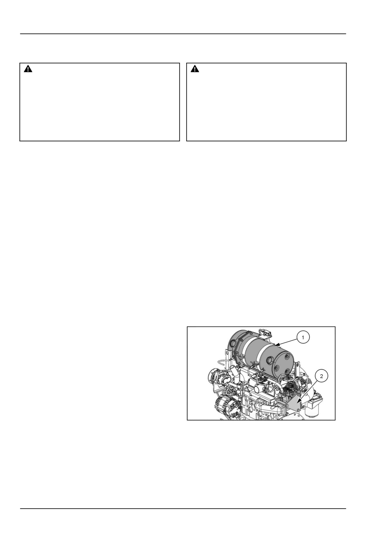
To meet tier 4 emission regulations the Diesel Oxidation
Catalyst and Diesel Particulate Filter (1) and burner (2)
are installed on your tractor and are located under the
engine hood of the tractor.
NHIL13CT01215AA
1
It is very important to read this operator’s manual and un-
derstand the safe operation of your tractor. If you have
any questions in the operation of this emission system
please contact your NEW HOLLAND dealer
4-2
4 - OPERATING INSTRUCTIONS
Fuel and engine lubrication oil specifica-
tions
Fuel specification
• Use only Ultra Low Sulfur diesel fuel (S15) in your trac-
tor.
NOTICE: Use of diesel fuel other than Ultra Low Sulfur
fuel may adversely affect the engine and the (DPF) per-
formance.
Engine oil specification
• Use only (DPF) compatible (CJ-4) oil in your tractor en-
gine.
NOTICE: Use of any engine oil other than (CJ-4) may
clog the (DPF) earlier than expected and fuel usage may
increase.
4-3
4 - OPERATING INSTRUCTIONS
Auto regeneration mode operation
WARNING
Fire hazard!
During the Diesel Particulate Filter
(DPF)
forced regeneration process the exhaust
stack and fixed hood area becomes extremely
hot. Park the machine outside and away from
combustible or highly flammable material.
Failure to comply could result in death or se-
rious injury.
W1165B
In this operational mode, the operator does not have to
NHIL13CT01216AA
2
take any actions, the system is activated automatically by
the engine electronic controller.
The following conditions will activate the burner:
• Soot load of (DPF) is 60% or more of capacity.
• Every four hours of tractor operation after last regener-
ation.
• Engine exhaust temperature reaches designated re-
generation temperature.
•
(DPF) inhibited indicator light is “OFF”.
NOTE: Duration of regeneration operation is approxi-
mately 30 to 40 minutes. During the regeneration it is
NHIL13CT01218AA
3
normal to have a smell of burning or overheating.
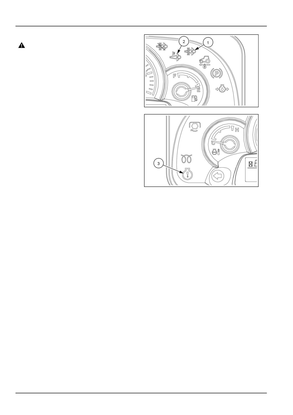
During the regeneration operation, the (DPF) regenera-
tion indicator light (1) and (DPF) temperature indicator
light (2) will both be illuminated.
Depending on the soot rate of the (DPF) the (DPF) regen-
eration indicator light will show several different blinking
frequencies during the regeneration process.
The engine warning indicator light (3) will blink when there
is a excessive soot load in the (DPF). Stop working tractor
and prepare for (DPF) regeneration.
NOTICE: Switching the key switch to the “OFF” position
during regeneration mode is not recommended. Soot in
the (DPF) will not be completely burned and may increase
fuel consumption or damage to the regeneration burner. It
is recommended for users to operate regeneration mode
until all indicator lights are “OFF” with the key switch in the
“ON” position.
NOTE: In case of turning off the engine during regenera-
tion mode, the regeneration mode will resume again when
restarting the engine.
NOTICE: After heavy work of tractor, allow tractor to run at
idle for approximately five minutes to allow components in
the fuel circuit to cool down. If you try to start the tractor
before this cooling operation has completed, the engine
will not run. This will lead to longer crank times before the
engine runs.
4-4
4 - OPERATING INSTRUCTIONS
Inhibited regeneration mode operation
NOTICE: Only use this mode when regeneration needs to
be delayed or stopped because of an operation condition
that may risk a fire hazard due to high exhaust tempera-
tures during regeneration.
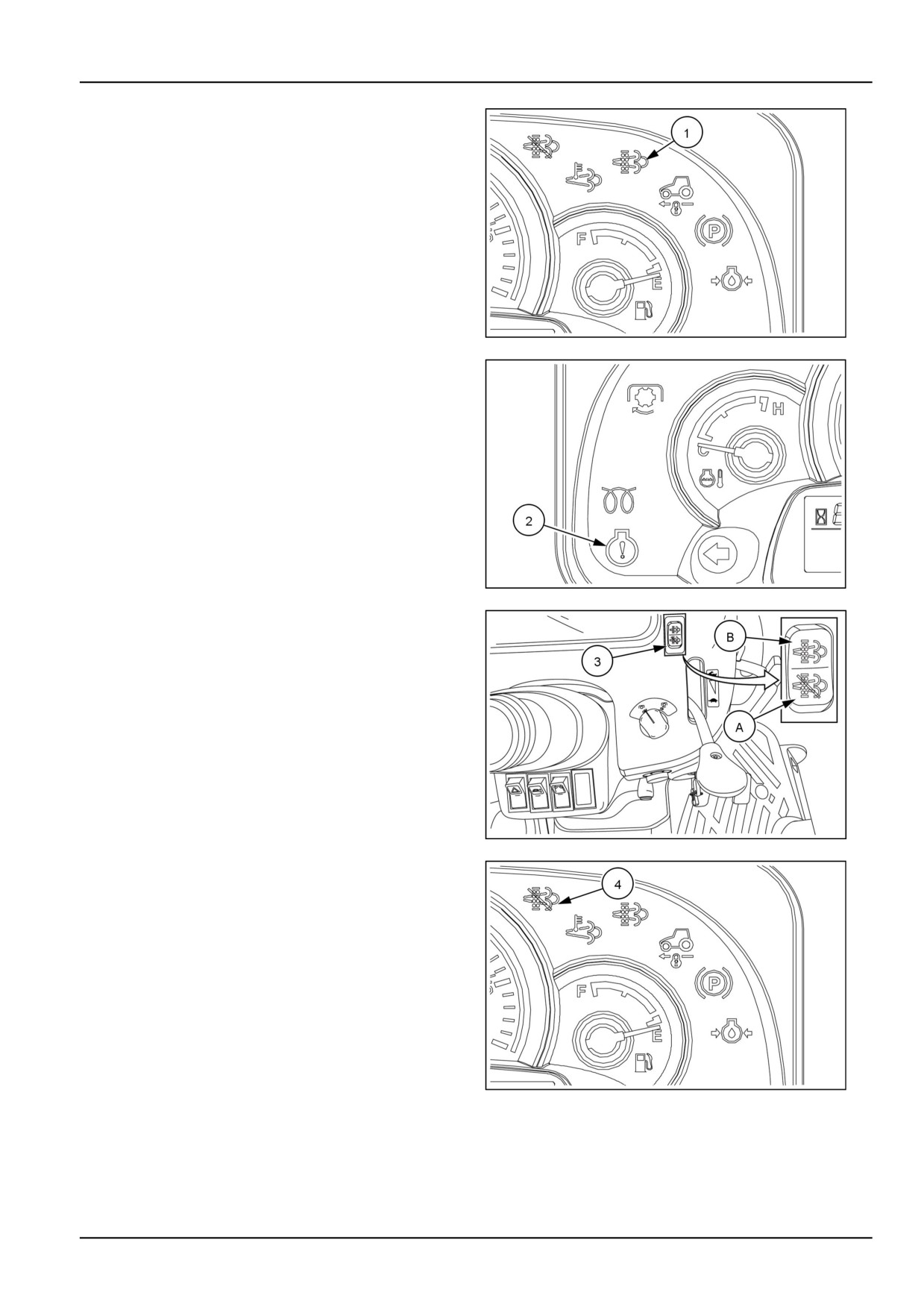
NOTE: When the (DPF) regeneration indicator light (1)
and engine warning light (2) are blinking during the regen-
eration process, the inhibited regeneration mode cannot
be set.
The regeneration mode can be delayed or stopped by the
use of the (DPF) switch (3) that is located on the right-
hand side of the dash.
NHIL13CT01216AA
4
To set the inhibited regeneration mode:
1. Press the lower side (A) of the (DPF) switch (3) for
approximately two seconds.
2. When inhibited mode is activated the (DPF) inhibited
indicator light (4) will be illuminated.
NOTICE: When tractor arrives at a safe regeneration lo-
cation, press the upper side (B) of the (DPF) switch for
NHIL13CT01218AA
5
approximately two seconds to return the regeneration sys-
tem to the auto regeneration mode. If regeneration sys-
tem is not returned to auto mode, excessive soot in the
(DPF) may overload the emission system and result in a
reduction of engine power or damage to the regeneration
system.
NOTICE: If, when notified by the instrument panel (DPF)
indicator lights that a regeneration of the (DPF) is needed
and the operator does not proceed with a regeneration of
the (DPF), the functionality of the (DPF) will be impaired.
If the operator continues to ignore or interrupt the regen-
eration notification the (DPF) may become damaged to
such an extent as to require the (DPF) to be replace by
an authorized NEW HOLLAND dealer.
NHIL14CT00050AA
6
To exit the inhibited regeneration mode:
1. Press the upper side (B) of the (DPF) switch (3) for
approximately two seconds.
2. When inhibited mode has been exited the (DPF) inhib-
ited indicator light (4) will not be illuminated.
NOTE: If the tractor is shut off during the inhibited mode,
when restarting the tractor, the regeneration system will
return to the auto regeneration mode.
NHIL13CT01216AA
7
4-5
4 - OPERATING INSTRUCTIONS
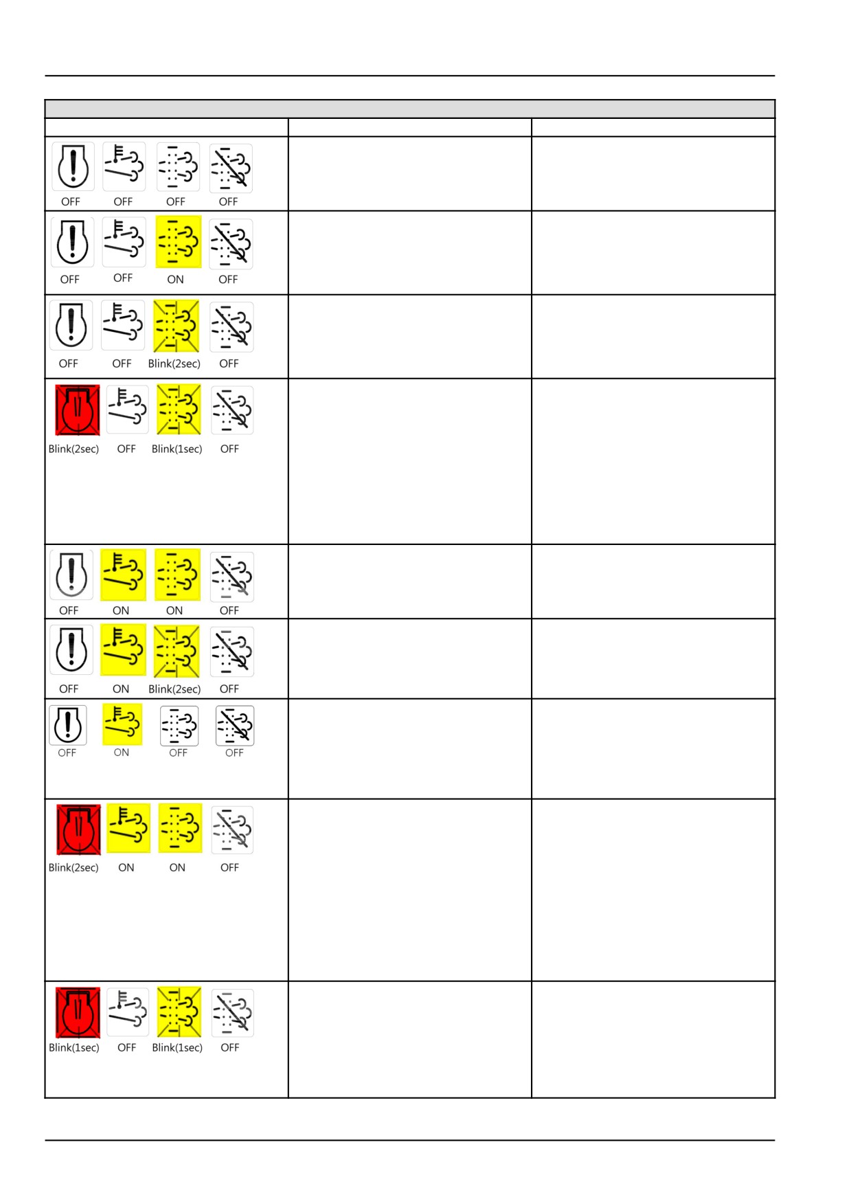
Combination of (DPF) indicator lights on the instrument panel
Indicator symbol
(DPF) Regeneration Mode
(DPF) Status and Work Restriction
No regeneration mode
The soot load in the (DPF) is below
60%.
Work is possible
Auto-regenration preparation mode
The soot load in the (DPF) is 60-80%
(DPF) will regenerate soon
automatically after engine is
started
Work is possible
Auto-regenration preparation mode
The soot load in the (DPF) is 80-100%
(DPF) will regenerate soon
automatically after engine is
started
Work is possible
Power limit preparation mode
The soot load in the (DPF) is
100-140%
(DPF) will regenerate soon
automatically after engine is
started
It is possible to start work after
completion of auto regeneration, with
all indicator lights are “OFF” and
engine speed has returned to normal
speed.
Auto-regeneration operation mode
The soot load in the (DPF) is
60-80% and (DPF) is regenerating
automatically
Work is possible
Auto-regeneration operation mode
The soot load in the (DPF) is
80-100% and (DPF) is regenerating
automatically
Work is possible
High exhaust temperature mode
The temperature at the (DPF) outlet
is over 300°C (572°F) after auto
regeneration
The indicator light will be turned of
under 300°C (572°F)
Work is possible
Power limit operation mode
The soot load in the (DPF) is
100-140% and (DPF) is regenerating
automatically.
Engine power is de-rated 50% and
engine speed is limited to 1800 rpm.
Have to STOP work
It is possible to start work after
completion of auto regeneration, with
all indicator lights are “OFF” and
engine speed has returned to normal
speed.
Engine shutdown mode
The soot load in the (DPF) is over
140% and the engine has been
shutdown.
Contact you authorized dealer
immediately. If restarting the engine,
the engine can run for only thirty
seconds to escape an emergency.
4-6
4 - OPERATING INSTRUCTIONS
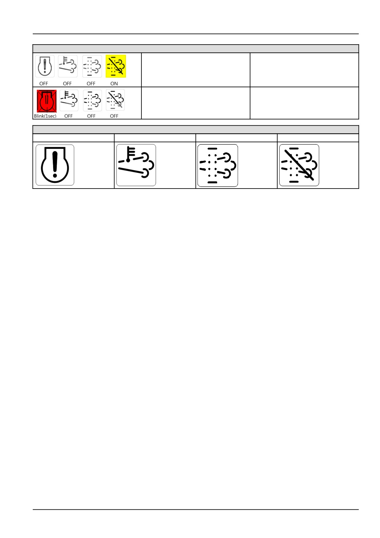
Combination of (DPF) indicator lights on the instrument panel
(DPF) inhibited operation mode
Work is possible.
Press the (DPF) switch to auto
regeneration after entering a safe
regeneration area.
Engine shutdown mode
Engine shut down with other
problems.
Contact your authorized dealer.
Indicator lights identification
Engine Warning
(DPF) Temperature
(DPF) Regeneration
(DPF) Inhibitor
4-7
4 - OPERATING INSTRUCTIONS
Power Take-Off (PTO) operation
Rear PTO
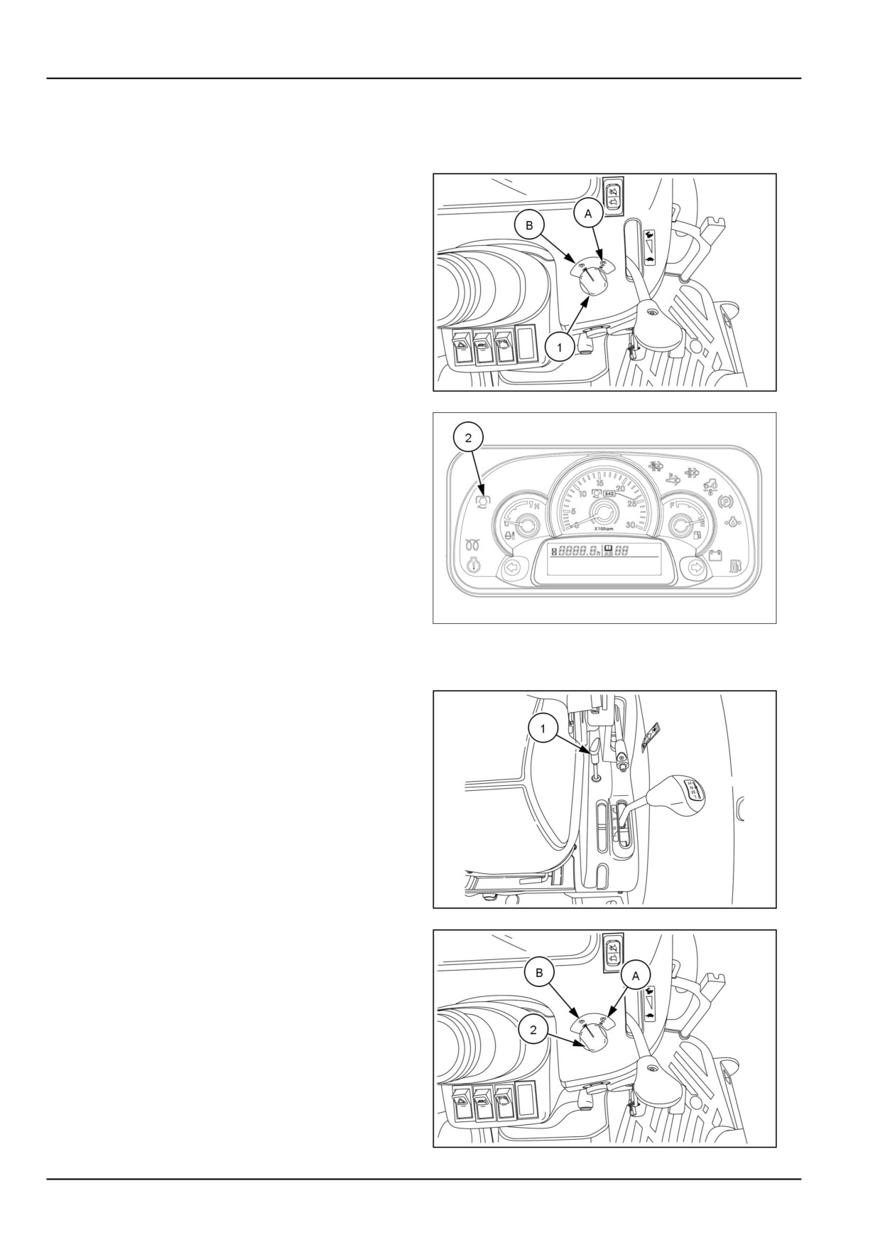
To engage the rear PTO:
1. Push the PTO switch (1) down and turn the switch to
the "ON" position (A).
NOTE: When the PTO switch is in the engaged “ON”
position, the PTO indicator light (2) will be illuminated
on the instrument panel.
2. The PTO system is totally independent of the tractor
ground speed, and the following operations can be
performed.
• The tractor ground travel can be stopped without stop-
ping the PTO.
NHIL13CT01005AA
1
• Stop the PTO by disengaging the PTO clutch without
stopping the tractor ground travel.
To disengage the rear PTO:
1. Push down on the PTO switch (1) and the switch will
automatically return to the "OFF" position (B).
NHIL14CT00054FA
2
Mid PTO (Optional)
To engage the mid PTO:
1. Pull up on the mid PTO lever (1)
2. Push down on the PTO switch (2) and turn the switch
to the "ON" position (A).
NOTE: When the mid PTO is engaged the rear PTO will
also be engaged. The mid PTO cannot be engaged sep-
arately.
To disengage mid PTO:
NHIL13CT01248AA
3
1. Push down on the PTO switch (2) and the switch will
automatically return to the "OFF" position (B).
2. Push the mid PTO lever down to the "OFF" position
(1).
NOTE: To start the engine the mid PTO lever must be in
the down (disengaged) position and the PTO switch in the
"OFF" position.
NHIL13CT01005AA
4
4-8
4 - OPERATING INSTRUCTIONS
Rear PTO operation without operator
present
WARNING
Entanglement hazard!
Before operating stationary Power Take-Off
(PTO) equipment, do the following: apply the
parking brake, place all controls in the neutral
position, and block all four wheels.
Failure to comply could result in death or se-
rious injury.
W0336A
NOTICE: The engine will shut off in approximately two
seconds if the operator leaves the seat without the trans-
mission shuttle shift lever or HST pedals in the neutral
position or the mid PTO lever not in the "OFF" position.
NOTE: The Mid PTO cannot be operated without an op-
erator present in the seat.
To operate the rear PTO without the operator in the seat
the following operations must be performed:
1. The transmission shuttle shift lever or HST pedals in
“NEUTRAL” position.
2. Park brake engaged.
3. Mid PTO in "OFF" position (if equipped).
With rear PTO in "ON" position, the alarm will sound
when the following conditions are present:
• Operator not in the seat.
• Park brake disengaged.
4-9
4 - OPERATING INSTRUCTIONS
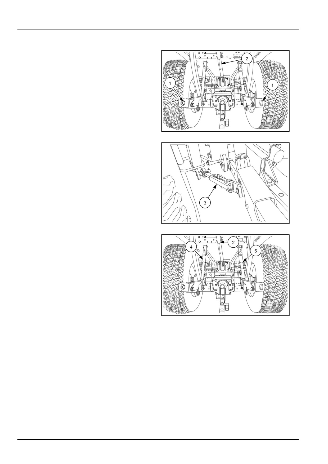
Three-point linkage
The tractor's three-point linkage is used to attach three-
point mounted equipment which is usually PTO operated,
such as rotary mowers, tillers, flail mowers, snowblowers,
etc. The three linkage points are the two lower lift arms
(1) and the top link (2) .
NHIL13CT01023AA
1
The three-point linkage has easy to adjust sway bars (3)
on each side of the hitch to control lateral movement of
the lift arms.
NHIL13CT01019AA
2
The length of the top link (2) and the height of the left-hand
(4) and right-hand (5) lift arms can be adjusted to ease the
attachment of implements and to level the implement after
attaching.
NHIL13CT01023AA
3
4-10
4 - OPERATING INSTRUCTIONS
Attaching three-point equipment
WARNING
Entanglement hazard!
Before attaching or detaching equipment or
changing the Power Take-Off (PTO) shaft: 1)
Apply the parking brake. 2) Move all controls
to neutral and PTO control knob to the dis-
engaged position. 3) Stop the engine and re-
move the key. 4) Wait for the PTO shaft to stop
turning before leaving the cab.
Failure to comply could result in death or se-
rious injury.
W0323A
NOTICE: When attaching mounted or semi mounted im-
plement to the three-point linkage, ensure that there is ad-
equate clearance between the implement and the rear of
the tractor. The clearances in the raised position should
be checked by raising the implement carefully with the po-
sition control lever. With the implement fully raised there
must be at least 100 mm (4 in). Clearance between the
implement and the nearest part of the tractor.
Most implements can be attached to the tractor as follows:
1. Position the tractor so that the lower link hitch points
are level with and slightly ahead of the implement hitch
pins. Carefully bring the tractor rearwards to match
the tractor and implement hitch points. First attach the
left-hand lower link, then by adjusting the leveling box,
attach the right lower link.
2. Lengthen or shorten the top link until the implement
mast pin can be inserted through the mast and upper
link of the implement.
3. When detaching the implement, the procedure is the
reverse of attaching. The following hints will make
detaching easier and safer.
• Always park the implement on a level, firm surface.
• Implement should be supported so that it cannot tip or
fall when detached from the tractor.
• Always relieve all hydraulic pressure in any remote
cylinders before detaching.
4-11
4 - OPERATING INSTRUCTIONS
Left-hand lift rod adjustment
WARNING
Crushing hazard!
Before disconnecting a lift rod from the lower
link, lower the attached implement to the
ground, and stop the engine. Make sure the
attached implement is correctly supported
and no pressure remains in the hydraulic
system before removing the lift rod securing
pins.
Failure to comply could result in death or se-
rious injury.
W0034A
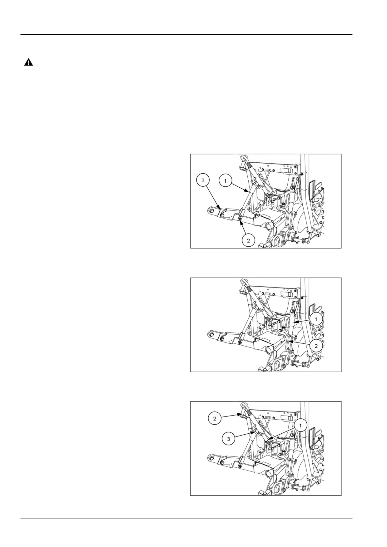
NOTICE: The left-hand lift rod
(1) is adjustable but
must be removed from the lift arm before length can be
changed.
To lengthen or shorten the left-hand lift rod (1) remove the
bolt and nut (2) from the lift rod and lower link (3). Rotate
the top half of the lift rod clockwise to reduce the length
and counter-clockwise to increase the length.
NHIL13CT01249AA
1
Right-hand lift rod adjustment
NOTICE: The right-hand lift rod is readily adjustable even
when connected between the lift arm and lower link.
To lengthen or shorten the right-hand lift rod (1) lift the
handle up (2) and rotate clockwise to reduce the length
and counter-clockwise to increase the length.
NHIL13CT01249AA
2
Top link adjustment
To adjust the top link length, loosen the jam nut (1). Hold
the link end (2) and rotate the handle (3) on the sleeve to
lengthen or shorten the top link. After adjustment tighten
the jam nut to prevent unwanted rotation of sleeve when
in use.
NHIL13CT01249AA
3
4-12
4 - OPERATING INSTRUCTIONS
Telescoping stabilizers and flex end links ad-
justment
Telescoping stabilizers and fixed end links are standard
equipment on the tractor, the flex end links are optional
equipment.
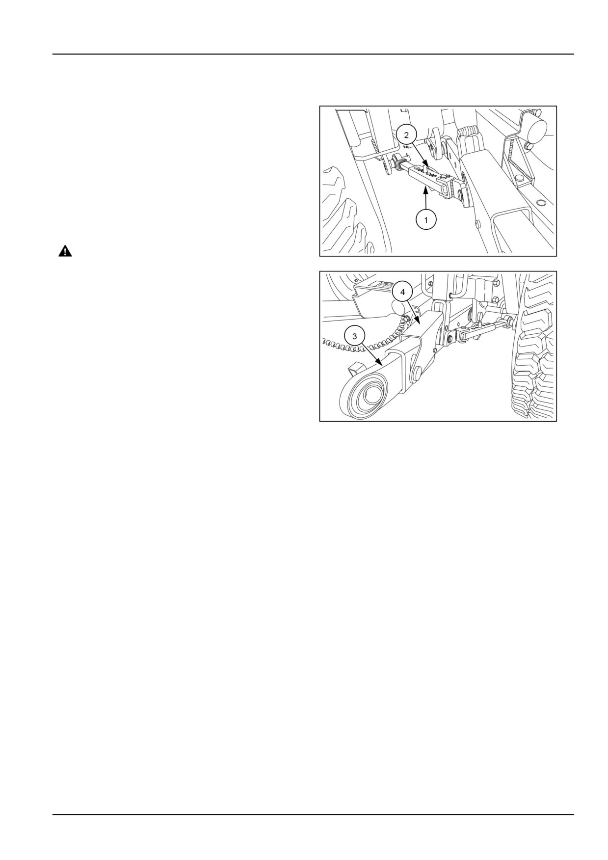
The telescoping stabilizers (1) use a pin and multiple hole
arrangement for easy adjustment, for side to side move-
ment of the three-point linkage.
To adjust the stabilizer, pull the pin (2) and adjust the sta-
bilizer and insert the pin into the desired hole.
NOTE: Cycle the three point linkage through the entire
travel and check for interference with the rear tires. If
interference is present, adjust stabilizers as needed.
WARNING
NHIL13CT01019AA
4
Machine damage can cause accidents!
Only operate three-point equipment with both
flex ends returned to the latched position.
Failure to comply could result in death or se-
rious injury.
W0467A
The flex ends (3) on the lower lift arms are adjusted by
pushing down on the clamp (4) and sliding the ends to the
desired length. Once the implement is attached, push in
on the flex ends until the ends are in the latched position
in the arms.
NHIL13CT01020AA
5
4-13
4 - OPERATING INSTRUCTIONS
Extendible drawbar
NOTICE: When transporting equipment on highways, a
safety chain with a tensile strength equal to the gross
weight of the implement should be installed between the
tractor and implement hitch.
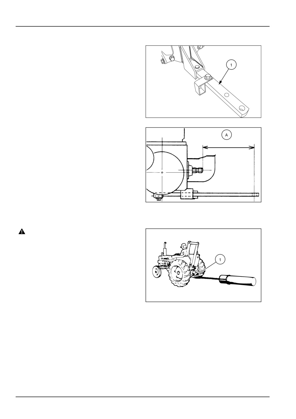
Your tractor is equipped with a fixed/extendible drawbar
(1) for towing equipment behind the tractor.
93100910
1
NOTICE: The drawbar is required to provide standard rear
PTO drawbar relationship.
20099087
2
(A)
356 mm (14 in)
WARNING
Overturning hazard!
Always use the drawbar, pick-up hitch,
or lower links in the lowered position for
pull-type work. Do not pull from the lower
links if they are above the horizontal position.
Failure to comply could result in death or se-
rious injury.
W0417A
NHIL13CT00908AA
3
(1)
Drawbar
4-14
4 - OPERATING INSTRUCTIONS
Hydraulic lift rocker
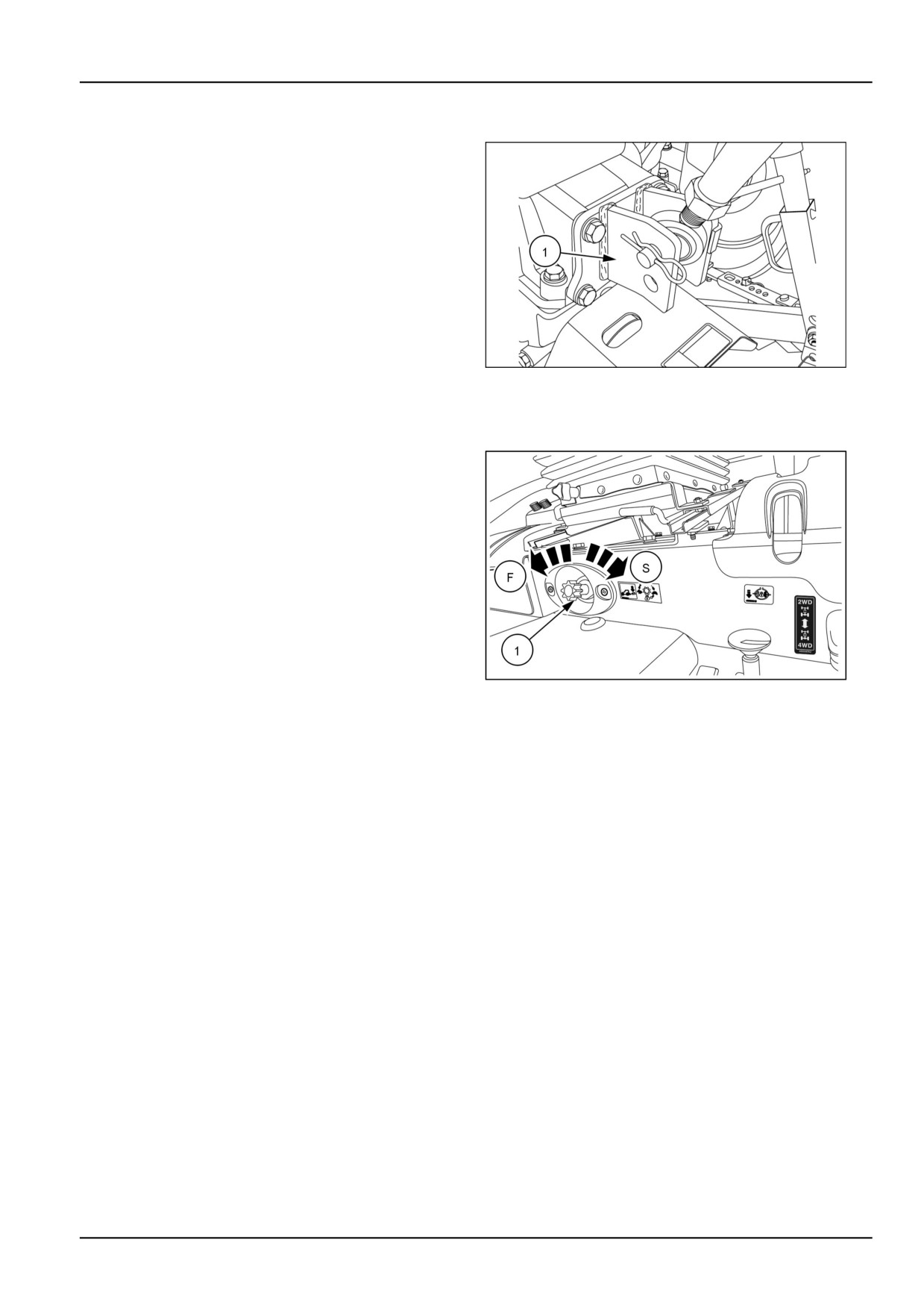
The hydraulic lift rocker (1) has two holes for attaching
the upper link. Attach the link using the lower hole for
light draft loads, such as mowers. Attach the link to the
top hole for heavier draft loads, such as ground engaging
equipment.
93099353
1
Hydraulic Power Lift (HPL) drop rate control valve
The drop rate control valve (1) provides an adjustment to
regulate the flow of oil from the lift cylinder. This allows the
operator to slow or increase the rate of drop of the lower
links.
Turn the drop rate control valve "IN" (clockwise) to de-
crease the rate of drop. Turn the valve "OUT" (counter-
clockwise) to increase the rate of drop.
The drop rate control valve must be opened before the
hydraulic lift control will lower. If the valve is turned all
the way "IN" (clockwise), the lower links can be raised to
maximum height but cannot be lowered.
NHIL13CT01379AA
1
(F) Fast
(S) Slow
NOTE: The drop rate control valve needs to be adjusted
accordingly to the amount of weight being carried on the
rear hitch arms.
4-15
4 - OPERATING INSTRUCTIONS
STARTING THE UNIT
Key switch
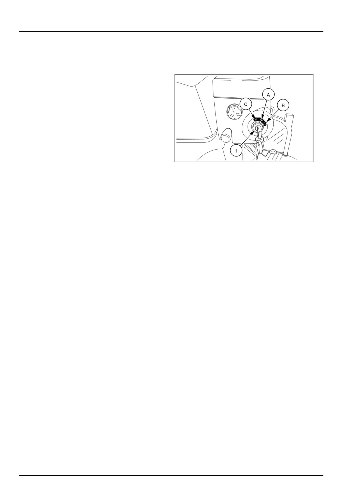
The key switch (1) is located on the right-hand side of the
rear hood panel just below the hand throttle. Turning the
key to the middle "ON" position (A) activates the lights,
instruments, and preheat system. The engine starts when
the key is turned to the extreme right "START" position
(B). An internal spring returns the key to the middle "ON"
position when released.
Turning the key to the extreme left "STOP" position (C)
will shut off the engine.
NHIL13CT01006AA
1
4-16
4 - OPERATING INSTRUCTIONS
Cold starting aids
Your tractor has a diesel engine. Before starting a cold en-
gine, the engine cylinder head precombustion chambers
must be heated.
WARNING
Explosion hazard!
DO NOT use ether starting fluid. Serious en-
gine damage, explosion, death, or serious per-
sonal injury could occur.
Failure to comply could result in death or se-
rious injury.
W0148A
NOTICE: When starting the machine after long periods,
avoid immediate use of hydraulics. It is necessary to al-
low time for enough lubrication of all moving parts before
subjecting them to work loads, particularly if outdoor tem-
peratures approach 0°C (32°F ). Run the engine at 1300
to 1500 RPM for approximately fifteen minutes to bring the
rear drive oil up to normal operating temperature. Failure
to comply could seriously damage machine.
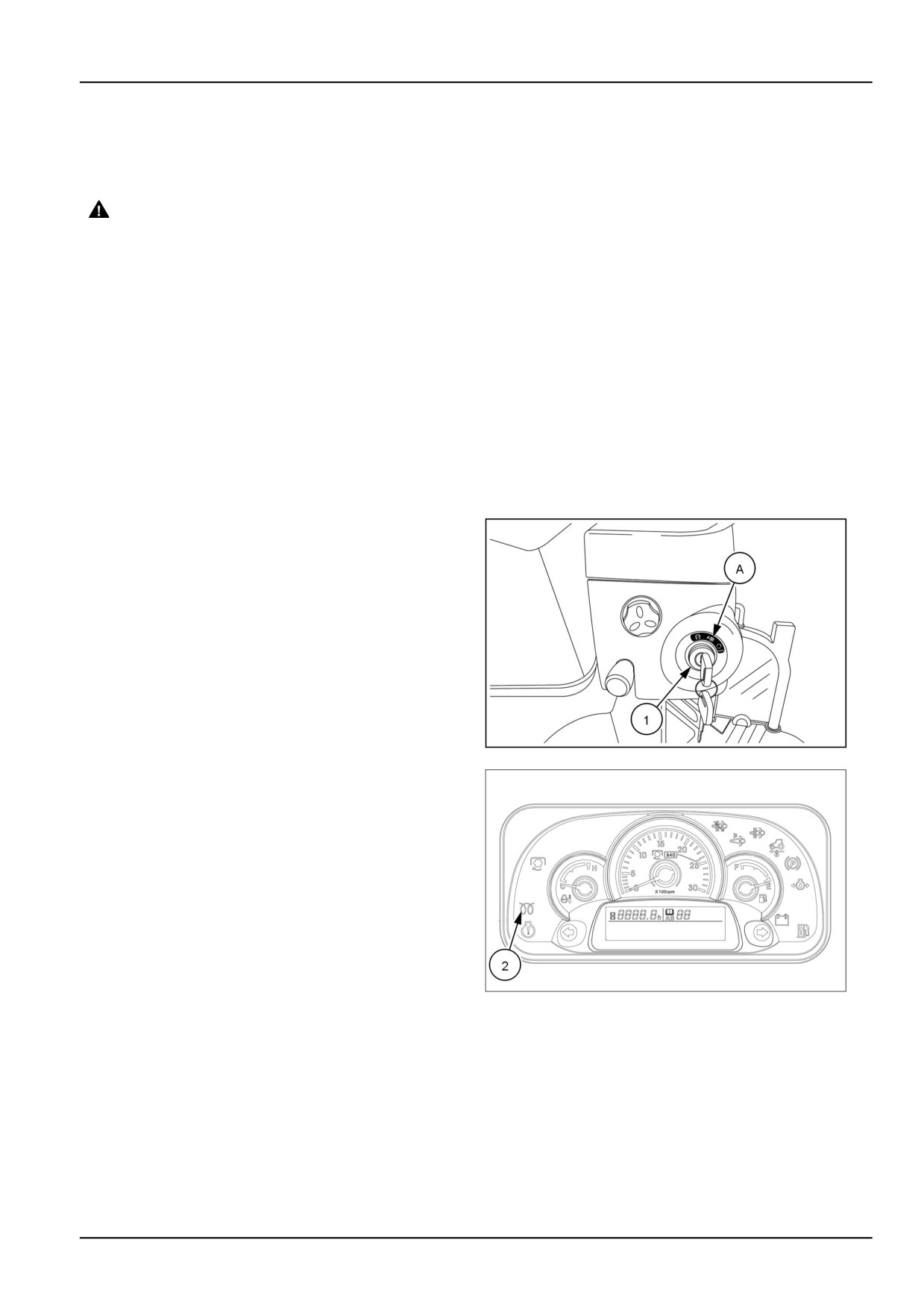
To preheat the engine, turn the key switch (1) to the middle
"ON" position (A). The cold start indicator light (2) will il-
luminate from three to twelve seconds, depending on the
ambient temperature. The glow plugs heat the precom-
bustion chambers of the engine cylinder head during this
time. After the indicator light goes off the tractor can be
started.
NOTE: The preheat is auto-timed, when the indicator light
goes off, the power to the glow plugs is also removed.
NOTE: A coolant immersion heater is available as a
dealer installed option. This heater allows for easier
starting in temperatures below -17.7 °C (0 °F) by warming
the engine coolant.
NHIL13CT01006AA
1
NHIL14CT00054FA
2
4-17
4 - OPERATING INSTRUCTIONS
Starting the engine
WARNING
Run-over hazard!
When attempting to start the engine, always sit in the operator´s seat with the parking brake engaged
and all control elements in neutral. Never attempt to start the engine while standing beside the ma-
chine.
Failure to comply could result in death or serious injury.
W0967B
Gear model
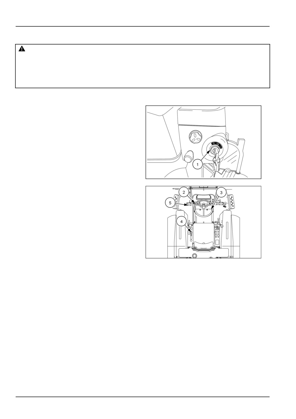
The key switch (1) allows activation of the starter motor
and fuel delivery only when:
• The transmission forward/reverse shuttle lever (2) is in
the neutral position.
• The PTO switch (3) is in the "OFF" position.
• The mid PTO lever (4) is in the "OFF" position (if
equipped).
• The clutch pedal (5) is depressed.
NOTE: Although the tractor can be started with the op-
erator out of the seat, this practice is not recommended.
However, an alarm will sound if the park brake is not en-
NHIL13CT01006AA
1
gaged, indicating that the operator needs to engage the
park brake.
93100852
2
4-18
4 - OPERATING INSTRUCTIONS
Starting procedure (Gear model)
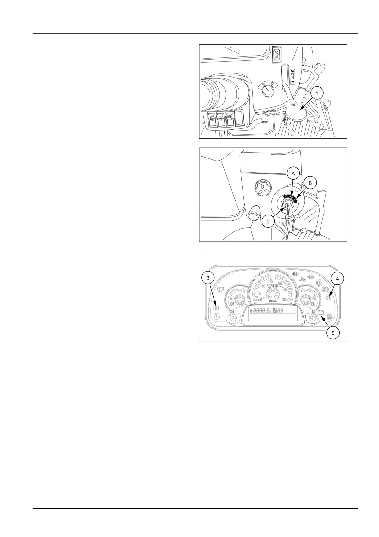
1. Push the hand throttle lever (1) forward to approxi-
mately the middle position.
2. Turn the key switch (2) to the middle "ON" position (A)
and check if the cold start (3) engine oil pressure (4)
and battery charge (5) indicator lights are illuminated.
3. Wait until the cold start indicator light (3) goes off, ap-
proximately three to twelve seconds, depending on
ambient temperature.
4. Turn the key to the extreme right to the "START" posi-
tion (B) . As soon as the engine starts, release the key
NHIL13CT01005AA
3
to allow it to return to the middle "ON" position.
NOTICE: Do not engage the starting motor continu-
ously for more than 10 seconds. Doing so may cause
starting motor failure.
5. Check if the engine oil pressure (4) and battery charge
(5) indicator lights are illuminated, the lights should
be off. If any of these indicator lights are illuminated,
shut off the engine immediately and check engine for
possible problem.
NHIL13CT01006AA
4
NHIL14CT00054FA
5
4-19
4 - OPERATING INSTRUCTIONS
HST model
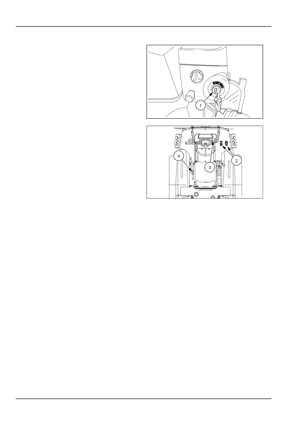
The key switch (1) allows activation of the starter motor
and fuel delivery only when:
• HST forward/reverse pedals (2) are in the neutral posi-
tion
• PTO switch (3) is in the "OFF" position.
• Mid PTO lever (4) is in the "OFF" position (if equipped)
NOTE: Although the tractor can be started with the op-
erator out of the seat, this practice is not recommended.
However, an alarm will sound if the park brake is not en-
gaged, indicating that the operator needs to engage the
park brake.
NHIL13CT01006AA
6
93100853
7
4-20
4 - OPERATING INSTRUCTIONS
Starting procedure (HST model)
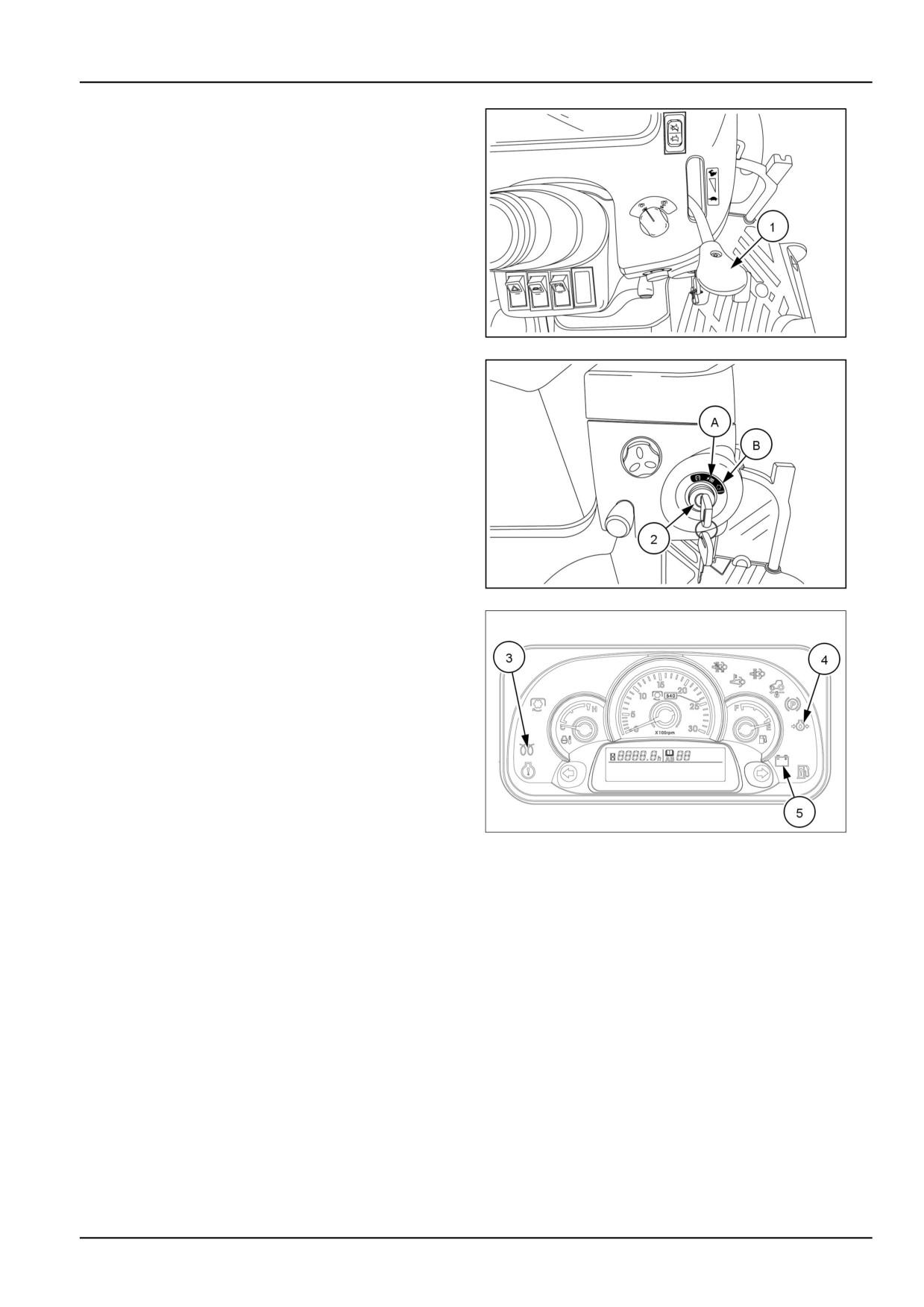
1. Push the hand throttle lever (1) forward to approxi-
mately the middle position.
2. Turn the key switch (2) to the middle "ON" position (A)
and check if the cold start (3) engine oil pressure (4)
and battery charge (5) indicator lights are illuminated.
3. Wait until the cold start indicator light (3) goes off, ap-
proximately three to twelve seconds, depending on
ambient temperature.
4. Turn the key to the extreme right to the "START" posi-
tion (B) . As soon as the engine starts, release the key
NHIL13CT01005AA
8
to allow it to return to the middle "ON" position.
NOTICE: Do not engage the starting motor continu-
ously for more than 10 seconds. Doing so may cause
starting motor failure.
5. Check if the engine oil pressure (4) and battery charge
(5) indicator lights are illuminated, the lights should
be off. If any of these indicator lights are illuminated,
shut off the engine immediately and check engine for
possible problem.
NHIL13CT01006AA
9
NHIL14CT00054FA
10
4-21

4 - OPERATING INSTRUCTIONS
Operator presence system (start operation)
Transmission
Transmis-
Operator
Rear PTO
Mid PTO
Park Brake
Clutch Pedal
Condition
Type
sion
HST pedals
HST
Out of Seat
Off
Off
Engaged
NA
Start
in Neutral
HST pedals
Start with
HST
Out of Seat
Off
Off
Disengaged
NA
in Neutral
Alarm
HST pedals
HST
In Seat
Off
Off
Engaged
NA
Start
in Neutral
HST pedals
Start with
HST
In Seat
Off
Off
Disengaged
NA
in Neutral
Alarm
Shuttle in
Gear
Out of Seat
Off
Off
Engaged
Depressed
Start
Neutral
Shuttle in
Start with
Gear
Out of Seat
Off
Off
Disengaged
Depressed
Neutral
Alarm
Shuttle in
Gear
In Seat
Off
Off
Engaged
Depressed
Start
Neutral
Shuttle in
Start with
Gear
In Seat
Off
Off
Disengaged
Depressed
Neutral
Alarm
NOTE: For starting, if Rear PTO, Mid PTO or Transmission is engaged, tractor will not start
Operator presence system (run operation)
NOTE: The following conditions are for when the engine is running and the operator gets out of the seat.
Transmission Type
Rear PTO
Mid PTO
Transmission
Park Brake
Condition
Gear/HST
Off
Off
Neutral
Disengaged
Alarm
Gear/HST
On
Off
Neutral
Engaged
No Alarm
Gear/HST
On
Off
Neutral
Disengaged
Alarm
In Gear or HST
Gear/HST
Off
Off
Either
Shutdown
pedal depressed
In Gear or HST
Gear/HST
On
Off
Either
Shutdown
pedal depressed
In Gear or HST
Gear/HST
On
On
Either
Shutdown
pedal depressed
Gear/HST
Off
On
Neutral
Either
Shutdown
4-22
4 - OPERATING INSTRUCTIONS
Starting the tractor with jumper cables
WARNING
WARNING
Unexpected machine movement!
Explosion hazard!
Always sit in the operator's seat to operate the
When jump-starting the machine, connect
machine. DO NOT bypass the key start switch.
and disconnect the jumper cables exactly as
Sudden and unexpected machine movement
indicated in this manual. DO NOT connect
or machine runaway could result.
the jumper cables to the machine battery ter-
Failure to comply could result in death or se-
minals. Make sure no persons are near the
rious injury.
connecting points before starting the engine.
W0464A
Start the engine from the operator’s seat.
Failure to comply could result in death or se-
WARNING
rious injury.
W0342A
Explosive gas!
Batteries emit explosive hydrogen gas and
other fumes while charging. Ventilate the
charging area. Keep the battery away from
sparks, open flames, and other ignition
sources. Never charge a frozen battery.
Failure to comply could result in death or se-
rious injury.
W0005A
NOTICE: When using a auxiliary battery to start the en-
gine, ensure that the polarity of the jumper cables are cor-
rect, POSITIVE to POSITIVE, NEGATIVE to NEGATIVE,
or the alternator or battery may be damaged.
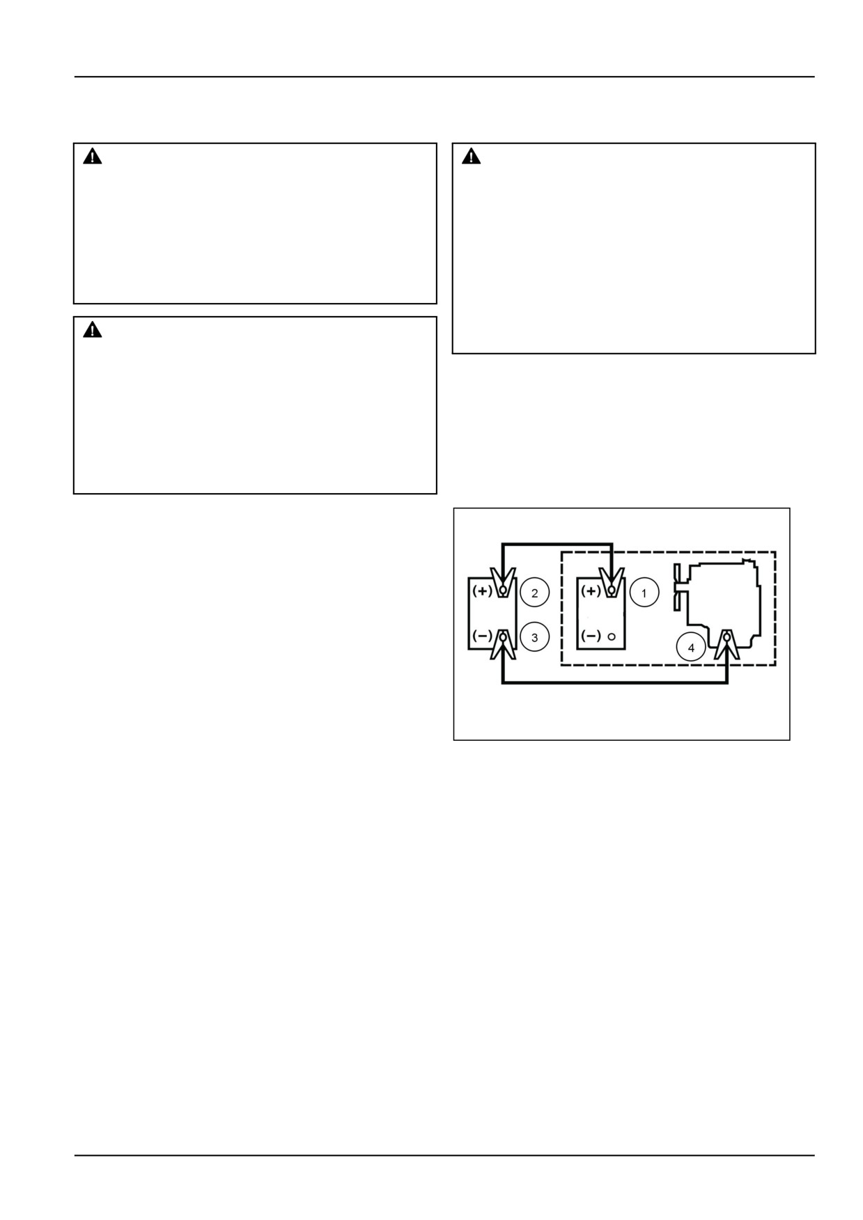
If you must use jumper cables to start the tractor:
1. Shield your eyes.
2. Connect the red end of the jumper cable to the positive
(+) battery terminal (1) on the tractor and connect the
other red end to the positive (+) battery terminal (2) on
the auxiliary battery.
3. Connect the black end of the jumper cable to the neg-
ative (-) battery terminal (3) on the auxiliary battery,
then connect the other black end to a tractor frame
20100878
1
ground or engine ground (4). Finally, start the tractor
by following the safe starting procedures outlined un-
der See Engine starting system - Operating .
4. When the engine starts allow the engine to idle, and
turn on all electrical equipment (lights, etc.) This will
help protect the alternator from possible damage due
to changes in load when disconnecting the jumper ca-
bles.
5. Disconnect the jumper cables in reverse order, dis-
connect the black end from the tractor frame or en-
gine ground (4) then disconnect the other black end
from the negative (-) battery terminal (3) on the auxil-
iary battery. Disconnect the red end from the positive
(+) battery terminal (2) on the auxiliary battery, then
remove the other red end from the positive (+) battery
terminal (1) on the tractor battery.
4-23
4 - OPERATING INSTRUCTIONS
STOPPING THE UNIT
Stopping the engine
To stop the engine, carry out the following procedures:
1. Remain in the operator seat.
2. Pull the hand throttle lever rearward to the idle posi-
tion.
3. Engage the park brake.
4. Ensure all gear shift levers, range levers or shuttle shift
lever are in the neutral position and the PTO switch is
in the "OFF" position.
5. Push the HPL control lever forward to lower imple-
ments to the ground.
6. Turn the key to the "STOP" position to shut the engine
off.
NOTE: When the key is turned to the "STOP" position
and the park brake is NOT engaged, an alarm will sound.
The alarm will continue to sound for approximately ten
seconds or until the park brake is engaged.
NOTE: If the key is not left in the "STOP" position after
the engine has stopped, the warning lights will remain on
and discharge the battery.
4-24
4 - OPERATING INSTRUCTIONS
Emergency stopping
Gear model
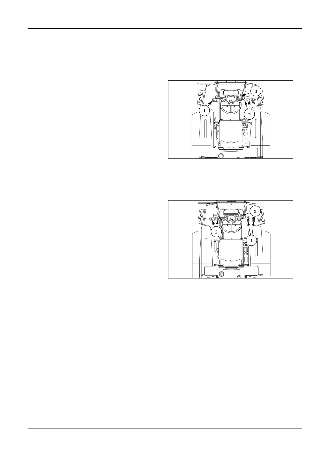
To make a emergency stop carry out the following proce-
dures:
1. Depress the clutch pedal (1) and brake pedals (2) at
the same time.
2. Pull the hand throttle lever (3) rearward to reduce the
engine speed.
93100852
1
HST model
To make a emergency stop carry out the following proce-
dures:
1. Release the HST forward or reverse pedal (1) imme-
diately and depress the brake pedals (2).
2. Pull the hand throttle lever (3) rearward to reduce en-
gine speed.
93100853
2
4-25
4 - OPERATING INSTRUCTIONS
Brakes
Brake pedals
WARNING
Loss of control hazard!
Always reduce the traveling speed and use the
steering wheel while you make a turn. When
you operate the machine at high speeds, never
attempt to make sharp turns by using the turn-
ing brake pedals. If you use the individual
brakes at high speeds, the machine could be-
come machine unstable.
Failure to comply could result in death or se-
rious injury.
W1237A
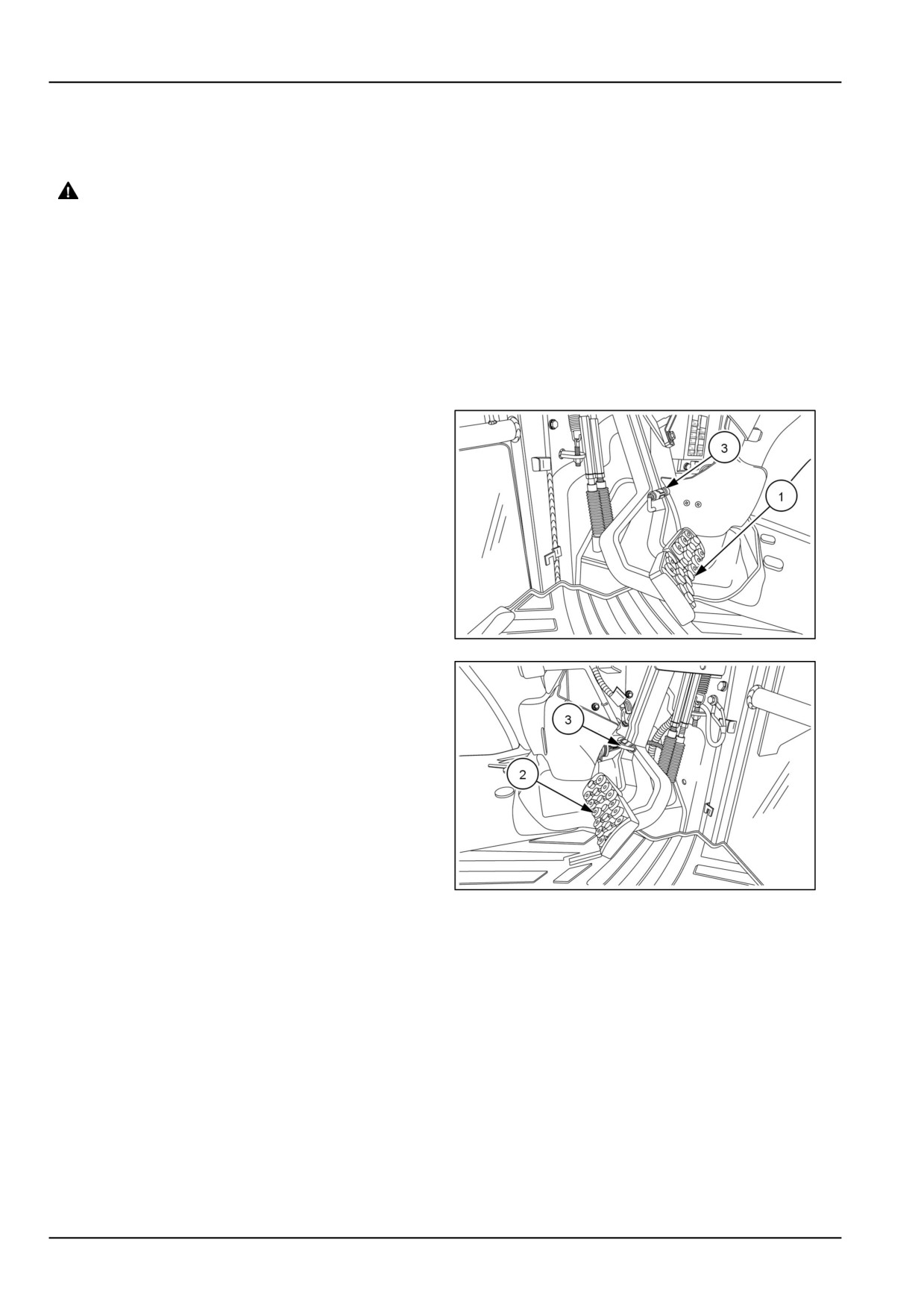
The right brake pedal controls the braking action of the
right rear wheel. The left brake pedal controls the braking
action of the left rear wheel.
The function of the brake pedals are identical for the HST
and gear model tractors except for the location of the ped-
als. The brake pedals (1) on a HST model tractor are lo-
cated on the left-hand side of the operators platform and
the brake pedals (2) on a gear model tractor are located
on the right-hand side of the operators platform.
Stopping the tractor
To stop a gear model tractor, depress both brake pedals
NHIL13CT01243AA
1
and the clutch pedal simultaneously.
To stop a HST model tractor, release the HST forward or
reverse pedal and depress both brake pedals simultane-
ously.
NOTE: To assist in making sharp turns at slow speed,
depress the right or left brake pedal as required.
NOTE: Depressing the brake pedals will disengage the
HST cruise control.
Brake pedal lock
The brake pedal connecting pin (3) is used to secure the
brake pedals together. Lock the pedals together when-
NHIL13CT01246AA
2
ever the tractor is operated at high speeds or when the
tractor is used on the highway.
4-26
4 - OPERATING INSTRUCTIONS
Park brake
WARNING
Equipment rolling hazard!
Firmly apply the handbrake. Stop the engine
before leaving the machine. The transmission
will not prevent the machine from rolling when
the engine is shut off.
Failure to comply could result in death or se-
rious injury.
W1144A
NOTICE: Ensure the park brake is fully disengaged before
driving the tractor.
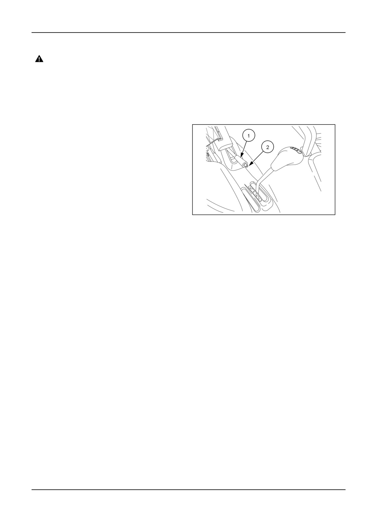
The park brake lever (1) is located on the left-hand side of
the operators platform. The park brake is used to secure
the brake pedals to prevent the tractor from moving while
parked.
To engage the park brake, lock the pedals together and
pull the park brake lever up while pressing the brake ped-
als down.
NOTE: Always engage the park brake when getting off the
tractor. If the park brake is not engaged or the operator
NHIL13CT01174AA
3
leaves the seat without engaging the park brake, a alarm
will sound. The alarm will continue to sound for approxi-
mately ten seconds or until the park brake is engaged.
To disengage the park brake, press the brake pedals
down and release the park brake lever by pushing button
(2) inwards and push the lever (1) down.
4-27
4 - OPERATING INSTRUCTIONS
MOVING THE UNIT
Steering wheel adjustment
The tractor is equipped with an adjustable steering wheel
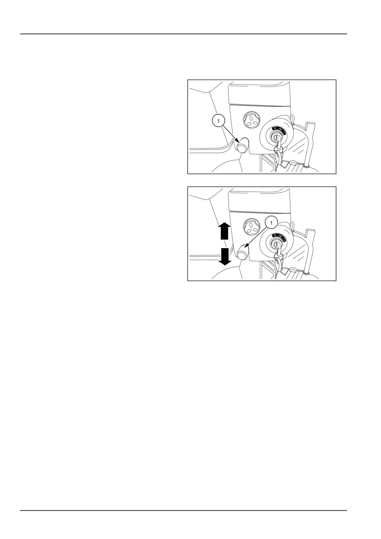
which can tilt. The tilt steering lever (1) is located on the
right-hand side of the steering column.
NHIL13CT01006AA
1
1. To tilt the wheel, push down on the lever (1) and move
the steering wheel to the desired position.
2. Pull the lever upwards (1) to lock the steering wheel in
place.
3. Use this feature to gain additional clearance when
mounting and dismounting the tractor.
NHIL13CT01006AA
2
4-28
4 - OPERATING INSTRUCTIONS
Steering operation
The tractor has a hydraulic steering system which pro-
vides convenience when operating the steering wheel. A
non-load reaction system keeps the steering wheel from
moving when the impact of the front wheels travel over
rough ground.
Operating notes
• If there is too much of a load in the front bucket, it could
be difficult to operate the steering wheel. In this case,
reduce the size of the load or move the tractor slowly
forward while turning the steering wheel in the direction
of desired travel.
• After turning the steering wheel fully, do not turn the
steering wheel fully to the same direction again. Unnec-
essary force is applied, which could damage the steer-
ing system.
NOTICE: Do not hold the steering wheel fully to the left or
right for more than 10 seconds, it could cause a failure in
the steering system.
• If an abnormal sound is heard while operating the steer-
ing wheel, this means that there is some air in the steer-
ing components line. In this case, turn the steering
wheel to left and right fully and hold for about 5 sec-
onds. The air should bleed out and the abnormal noise
should go away. If the sound does not go away take
your tractor to your authorized NEW HOLLAND dealer.
• When operating the tractor in cold weather, the abnor-
mal sound may be heard. In this case, warm up the
tractor before using to reduce the oil viscosity.
• If you use the tractor for a long period of time while
turning the steering wheel fully, the oil temperature will
increase which may cause the reduction of the product
life or the failure of the hydraulic steering system.
NOTE: If the engine stops, the hydraulic power for the
steering system will stop. Which will make the steering
wheel hard to turn.
4-29
4 - OPERATING INSTRUCTIONS
Transmission operation at low ambient temperatures
Warm up period
WARNING
The tractor hydraulic oil also serves as the tractor
Set the park brake during warm up operation. Set all
transmission fluid. During cold weather operation, the
shift levers to the "NEUTRAL" positions and place the
hydraulic oil viscosity increases. This increase in oil
PTO clutch lever in the "OFF" position during warm
viscosity restricts the oil's ability to flow and lubricate in
up operation. Failure to comply could result in death
the transmission and hydraulic circuits. The cold oil can
or serious injury.
result in abnormal noises and slower operation times due
to the increased oil viscosity.
M1478
NOTE: A warm up time at 50% rated engine speed is rec-
Recommended Warm-Up
Ambient Temperature
ommended to assure proper vehicle functionality, trans-
Time
mission lubrication and operation.
Above 0 °C (32 °F)
Minimum of 5 minutes
0 - -10 °C (32 - 14 °F)
5 to 10 minutes
NOTE: Do not operate the tractor under full load condition
-10 - -20 °C (14 - -4 °F)
10 to 15 minutes
until the hydraulic oil is sufficiently warmed up.
Below -20 °C (-4 °F)
More than 15 minutes
4-30
4 - OPERATING INSTRUCTIONS
Hydrostatic Transmission (HST) operation
The ground speed of tractors equipped with a hydrostatic
transmission is continuously variable, from zero to full
rated speed in each range. Speed is controlled by the
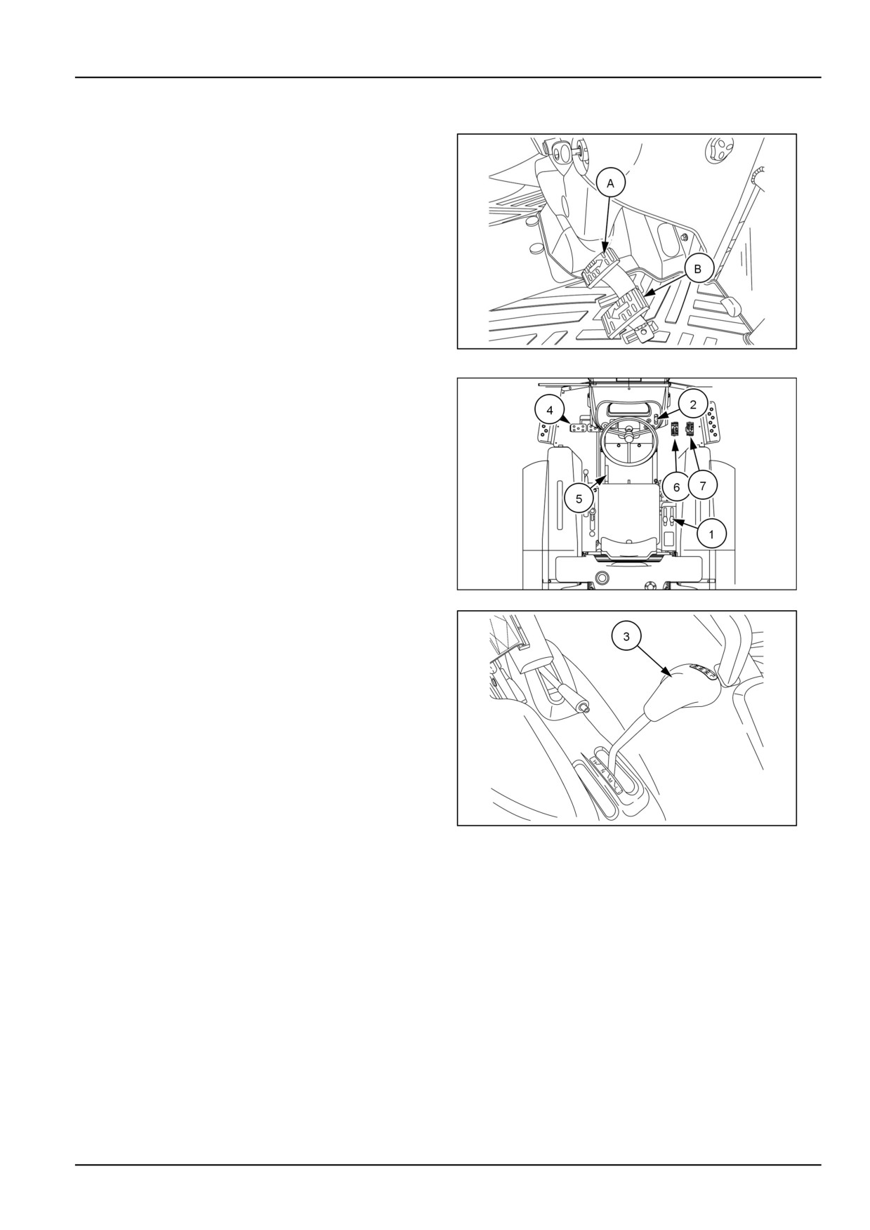
HST forward (A) and reverse (B) pedals located on the
right-hand operators platform.
NHIL13CT01172AA
1
To operate the HST transmission, carry out the following:
1. Start the engine and pull the HPL control lever (1) rear-
ward to lift the implement off the ground .
2. Move the hand throttle lever (2) forward until the en-
gine speed is above 1500 RPM.
3. Place the range gear shift lever (3) in the desired
range.
4. Depress the brake pedals (4) and disengage the park
brake lever (5).
5. For forward travel, depress the forward pedal (6) un-
til the desired ground speed is reached. For reverse
93100853
2
travel, depress the rear pedal (7). Unless the HST
cruise control switch is in the engaged position, the
transmission returns to neutral and the tractor stops
when the pedal is released.
NOTE: Depress the HST pedals slowly, fast move-
ment of the pedals will cause the tractor to move sud-
denly.
NOTE: To change the range speed, release the HST
pedals and bring the tractor to a stop and select the
desired range.
NHIL13CT01174AA
3
4-31
4 - OPERATING INSTRUCTIONS
Cruise control operation
WARNING
Loss of control hazard!
To maintain optimum control of the machine,
do not use the cruise control at high speeds
or when roading.
Failure to comply could result in death or se-
rious injury.
W0978A
When the desired travel speed is reached, depress the
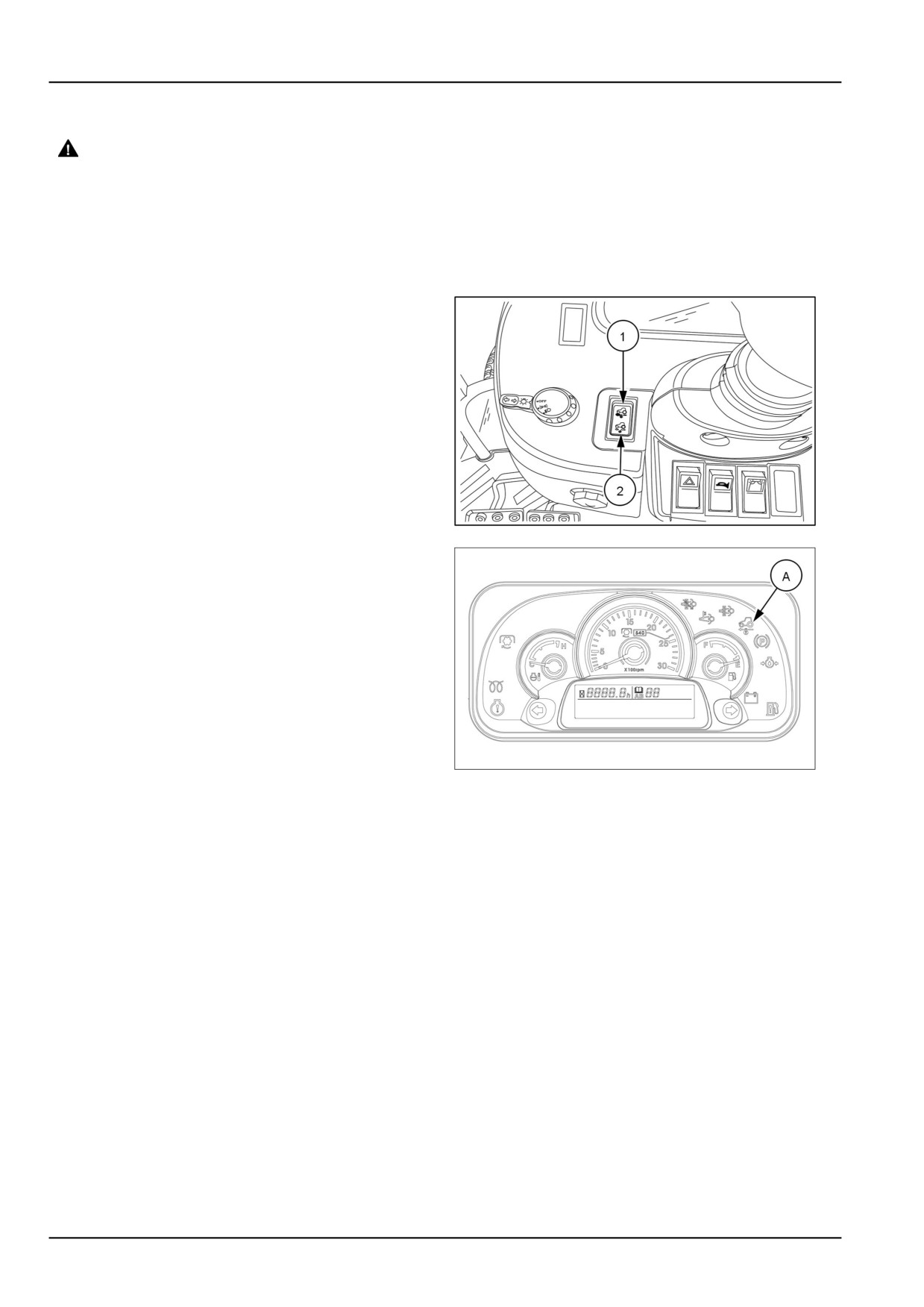
top half of the cruise control switch (1). A amber light (A)
will illuminate on the instrument panel indicating the cruise
control is engaged. To disengage the cruise control, de-
press the bottom half of the switch (2) or depress both
brake pedals. The amber light will extinguish, indicating
the cruise control is off.
NOTE: The rocker switch has three positions, the top half
engages the cruise control, the middle is neutral, and the
bottom half will disengage the cruise control.
NHIL13CT01036AA
4
NHIL14CT00054FA
5
4-32
4 - OPERATING INSTRUCTIONS
16 x 16 Synchronized transmission operation
The 16 x 16 gear transmission operates through the use
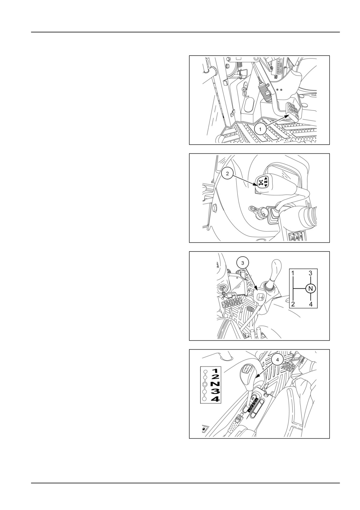
of a clutch pedal (1) a forward/reverse shuttle shift lever
(2) main transmission shift lever (3) and a range selector
lever (4).
The combinations of shuttle shift, main shift, and range
selector lever offer the operator a combination of sixteen
forward and sixteen reverse gears.
The main transmission shift lever (3) operates in a H-pat-
tern. To change gears while in a selected range, depress
the clutch pedal and shift the main gear shift lever into the
desired gear. The tractor does not have to be stopped be-
cause the main speed gears (1-4) are synchronized.
NHIL13CT01146AA
1
The range gear shift lever operates in a straight pattern
(1-2-N-3-4) with a neutral position between second and
third range.
NOTICE: Never attempt to engage or disengage the
range shift lever when the tractor is in motion.
NOTE: The shift patterns are shown as sitting in the op-
erators seat.
NHIL13CT01132AA
2
NHIL13CT01355AA
3
NHIL13CT01354AA
4
4-33