New Holland Boomer 41, Boomer 47 Compact Tractor. OPERATOR’S MANUAL (2014) - page 1
OPERATOR’S MANUAL
Boomer™ 41
Boomer™ 47
Compact Tractor
Part number 47578243
1st edition English
January 2014
Contents
1 GENERAL INFORMATION
Note to the Owner
1-1
Biodiesel fuel
1-2
Tractor intended use
1-3
Electro-magnetic compatibility (EMC)
1-4
Product identification
1-5
Operator's manual storage
1-6
Machine orientation
1-7
Proposition 65
1-8
Exhaust Gas Recirculation (EGR) - Diesel Particulate Filter (DPF) exhaust treatment - Product
overview
1-9
2 SAFETY INFORMATION
Precautionary statements
2-1
Safety rules
2-2
Do not operate tag
2-11
Roll Over Protective Structure (ROPS)
2-12
Ecology and the environment
2-13
Safety signs
2-14
Instructional signs
2-27
International symbols
2-34
3 CONTROLS AND INSTRUMENTS
OPERATOR'S SEAT
Seat belt
3-1
Seat controls
3-2
Roll Over Protective Structure (ROPS)
3-3
FORWARD CONTROLS
Instrument panel
3-5
Engine fault codes display
3-7
Cruise control
3-10
Transmission shuttle shift lever
3-11
Clutch pedal
3-12
Brake pedals
3-13
Foot throttle pedal
3-14
Hand throttle lever
3-15
Horn switch
3-16
Hazard light switch
3-17
Power Take-Off (PTO) switch
3-18
Key switch
3-19
Differential lock pedal
3-20
Hydrostatic transmision (HST) foot pedals
3-21
Tilt steering lever
3-22
Multifunction light switch
3-23
DPF switch
3-24
LEFT-HAND SIDE CONTROLS
Transmission range lever
3-25
Park brake
3-26
Front-wheel drive lever
3-27
Mid Power Take Off (PTO) lever - optional
3-28
RIGHT-HAND SIDE CONTROLS
Hydraulic power lift (HPL)
3-29
Draft control - optional
3-30
Rear remote control valve(s) - optional
3-31
Mid mount two spool control valve
3-32
Transmission main shift lever
3-34
Transmission range lever
3-35
EXTERIOR CONTROLS
Hood release latch
3-36
4 OPERATING INSTRUCTIONS
COMMISSIONING THE UNIT
Engine break-in procedure
4-1
Diesel Particulate Filter (DPF) regeneration
4-2
Power Take-Off (PTO) operation
4-8
Three-point linkage
4-10
Attaching three-point equipment
4-11
Extendible drawbar
4-14
Hydraulic lift rocker
4-15
Hydraulic Power Lift (HPL) drop rate control valve
4-15
STARTING THE UNIT
Key switch
4-16
Cold starting aids
4-17
Starting the engine
4-18
Starting the tractor with jumper cables
4-23
STOPPING THE UNIT
Stopping the engine
4-24
Emergency stopping
4-25
Brakes
4-26
MOVING THE UNIT
Steering wheel adjustment
4-28
Steering operation
4-29
Transmission operation at low ambient temperatures
4-30
Hydrostatic Transmission (HST) operation
4-31
16 x 16 Synchronized transmission operation
4-33
PARKING THE UNIT
Brakes and controls - Park
4-35
5 TRANSPORT OPERATIONS
ROAD TRANSPORT
External lighting - Identification
5-1
Hazard warning light operation
5-2
Turn signal operation
5-3
Road lights operation
5-4
Work lights operation
5-5
Rear work light (optional)
5-6
Driving the vehicle
5-7
SHIPPING TRANSPORT
Carrying the tractor on a transporter
5-8
RECOVERY TRANSPORT
Towing
5-8
6 WORKING OPERATIONS
GENERAL INFORMATION
Tractor ballasting
6-1
Tractor ballasting weights
6-2
Liquid ballast
6-4
7 MAINTENANCE
GENERAL INFORMATION
General information
7-1
Safety rules diesel fuel
7-3
Biodiesel fuel
7-3
Refueling the tractor
7-4
Consumables
7-5
MAINTENANCE CHART
Maintenance Chart
7-6
Every 10 hours or daily
Engine oil level
7-7
Engine cooling system
7-9
After first 50 hours
Engine oil and filter
7-10
Pre-fuel filter
7-12
Fuel filter
7-13
Hydraulic oil filter - Hydraulic system
7-14
Hydrostatic (HST) oil filter
7-15
Roll Over Protective Structure (ROPS)
7-16
Wheels bolt/nut
7-17
Every 50 hours
Grease fittings
7-18
Transmission fluid level
7-19
Clutch pedal free play
7-19
Brake pedal free play
7-20
Hydrostatic transmission (HST) neutral adjustment
7-20
Engine belts
7-21
Tires and wheels
7-22
Front axle differential oil level
7-23
Air cleaner - Primary element
7-24
Every 100 hours
Fuel filter
7-25
Every 300 hours
Engine oil and filter
7-26
Hydraulic filter
7-26
Hydrostatic (HST) oil filter - HST system
7-26
Pre-fuel filter
7-26
Engine belts
7-26
Wheels bolt/nut
7-26
Air cleaner primary element
7-27
Every 500 hours
Fuel filter
7-28
Every 600 hours
Front axle differential fluid
7-29
Transmission fluid
7-30
Every 1000 hours
Air cleaner inner element
7-31
Engine coolant
7-32
General maintenance
Fuel injection system - Bleed
7-33
Hydrostatic transmission (HST) neutral adjustment
7-35
Engine belts
7-36
Roll Over Protective Structure (ROPS) frame - Replace - Possible damage
7-37
Battery
7-37
Alternator
7-38
Fuses
7-39
Maxi-fuse
7-40
Headlight bulb
7-40
Tail/brake light bulb
7-41
Turn signal/hazard light bulb
7-41
Wheels bolt/nut
7-43
Front wheels toe-in
7-43
Brake pedal free play
7-44
Clutch pedal free play
7-45
STORAGE
Storing the tractor
7-46
Removal of tractor from storage
7-47
8 TROUBLESHOOTING
SYMPTOM(S)
Engine - Troubleshooting
8-1
Clutch - Troubleshooting
8-2
Hydraulic service brakes - Troubleshooting
8-2
Hydraulic Lift System - Troubleshooting
8-2
Steering - Troubleshooting
8-3
Hydrostatic transmission - Troubleshooting
8-4
Electrical system - Troubleshooting
8-4
9 SPECIFICATIONS
Wheel tread settings
9-1
Tire inflation pressures
9-2
Liquid ballast
9-3
General specifications
9-4
Tractor dimensions
9-9
10 ACCESSORIES
Optional equipment
10-1
11 FORMS AND DECLARATIONS
Delivery report - owner copy
11-3
Delivery report - dealer copy
11-5
1 - GENERAL INFORMATION
1 - GENERAL INFORMATION###_1_###
Note to the Owner
This manual contains information concerning the adjustment and maintenance of your new equipment. You have
purchased a dependable machine, but only by proper care and operation can you expect to receive the performance
and long service built into this equipment. Please have all operators read this manual carefully and keep it available
for ready reference.
Your NEW HOLLAND dealer will instruct you in the general operation of your new equipment. (Refer to the 'Delivery
Report' at the back of this manual.) Your dealer's staff of factory-trained service technicians will be glad to answer
any questions that may arise regarding the operation of your machine.
Your NEW HOLLAND dealer carries a complete line of genuine NEW HOLLAND service parts. These parts are
manufactured and carefully inspected to insure high quality and accurate fitting of any necessary replacement parts.
Be prepared to give your dealer the model and product identification number of your new equipment when ordering
parts. Locate these numbers now and record them below. Refer to the 'General Information' section of this manual
for the location of the model and product identification numbers of your machine.
PLEASE RECORD THE FOLLOWING INFORMATION
Model
Product Identification Number (PIN)
Date Purchased
Engine Model
Engine PIN
This is the safety alert symbol. It is used with and without signal words to alert you to potential
personal injury hazards. Obey all safety messages that follow this symbol to avoid possible
death or injury.
WARNING
Illustrations in this manual may show protective shielding open or removed to better illustrate a par-
ticular feature or adjustment.
Replace all shields before operating the machine.
Failure to comply could result in death or serious injury.
W0012A
IMPROVEMENTS
CNH America LLC is continually striving to improve its products. We reserve the right to make improvements or
changes when it becomes practical and possible to do so, without incurring any obligation to make changes or addi-
tions to the equipment sold previously.
1-1
1 - GENERAL INFORMATION
Biodiesel fuel
Fatty Acid Methyl Ester Biodiesel (Biodiesel Fuel) con-
With Biodiesel Fuels, it may be necessary to change the
sists of a family of fuels derived from vegetable oils
engine oil, engine oil filter and fuel filter elements more
treated with methyl esters.
frequently than with Diesel Fuels. Biodiesel Fuel can re-
move rust and particles from the inside of on-site fuel
NOTICE: Biodiesel Fuel blends are approved for your en-
storage tanks that would normally adhere to the sides
gine only if they comply with EN14214 Specification Stan-
of the tank. Like particle deposits that commonly occur
dards or ASTM D6751.
with Diesel Fuel, these particles can become trapped by
the machine fuel filters, causing blockage and shortening
NOTICE: It is imperative that you check which blend is ap-
filter life. In cold weather, this is more likely to happen.
proved for your engine with your NEW HOLLAND dealer.
Consult your NEW HOLLAND dealer for information on
Be aware that the use of Biodiesel Fuel that does not
cold weather operation and proper maintenance intervals
comply with the Standards mentioned above could lead
when using any Biodiesel Fuel blend.
to severe damage to the engine and fuel system of your
machine. The use of fuels that are not approved may void
When handling Biodiesel Fuel, care must be taken not to
NEW HOLLAND Warranty coverage.
allow water into the fuel supply. Biodiesel Fuel will actu-
ally attract moisture from the atmosphere.
Biodiesel Fuel Usage Conditions
Fuel tanks must be kept as full as possible to limit the
NOTICE: The Biodiesel Fuel must meet the fuel Specifi-
amount of air and water vapors in them. It may be nec-
cation mentioned above.
essary to drain the fuel filter water tap more frequently.
Biodiesel Fuel must be purchased from a trusted sup-
Potential oxidation and stability could be a problem with
plier that understands the product and maintains good
the fuel stored in the machine.
fuel quality. Biodiesel Fuel must be pre-blended by the
NOTICE: Machines must not be stored for more than
supplier. Mixing Biodiesel Fuels on-site can result incor-
three months with Biodiesel Fuel blends in the fuel sys-
rect mixture that can lead to problems with both engine
tem.
and fuel system.
If long storage periods are necessary, the engine must
Engine performance is affected by the use of Biodiesel
run on Diesel Fuel for 20 hours to flush the Biodiesel Fuel
Fuel. There may be up to 12 % reduction in power or
out of the engine fuel system prior to storage.
torque depending on the blend used.
NOTICE: Biodiesel Fuel must not be stored in on-site stor-
NOTICE: DO NOT modify the engine and/or injection
age tanks for more than three months.
pump settings to recover the reduced performance.
Any spillage of Biodiesel Fuel must be cleaned up imme-
The reduced power must be accepted if using any
diately before it can cause damage to the environment
Biodiesel Fuel blend.
and the paint finish of the machine.
Some modification may be required to allow your engine
Before using Biodiesel Fuel blends you should consult
to run Biodiesel Fuel. Consult you dealer for complete
with your dealer to receive full information about the ap-
information on these modifications.
proved blend for your machine and any detailed condi-
tions of its usage.
Biodiesel Fuel has a higher cloud point than Diesel Fuel.
NOTICE: Be aware that not fulfilling the requirements
NOTICE: The use of high Biodiesel Fuel blends are not
and conditions of Biodiesel Fuel usage will void your ma-
recommended in cold weather conditions.
chine’s NEW HOLLAND Warranty coverage.
1-2
1 - GENERAL INFORMATION
Tractor intended use
This machine was designed to power and propel itself. It is intended for agricultural use to pull or carry tractor attach-
ments or load and move materials when equipped with a front end loader with a variety of buckets.
PROHIBITED USAGE
No parts or attachments should be fitted to this machine, which have not been released by NEW HOLLAND. They
might affect machine operation, safety of the user or other people, stability or wear characteristics of the machine.
NOTICE: Use only approved accessories and attachments designed for your machine. Consult your dealer
on changes, additions or modifications that may be required for your machine. Do not make any unauthorized
modifications to your machine.
NOTICE: DO NOT use this machine for any purpose or in any manner other than as described in the manual, decals,
or other product safety information provided with the machine. These materials define the machine's intended use.
NOTICE: The engine and fuel system on your machine is designed and built to government emissions standards.
Tampering by dealer, customers, operators and users is strictly prohibited by law. Failure to comply could result in
government fines, rework charges, invalid warranty, legal action and possible confiscation of the machine until rework
to original condition is completed. Engine service and/or repairs must be done by a certified technician only!
NOTE: All persons who will be operating this machine shall possess a valid local vehicle operating permit and/or other
applicable local age work permits.
1-3
1 - GENERAL INFORMATION
Electro-magnetic compatibility (EMC)
Interference may arise as a result of add-on equipment that may not necessarily meet the required standards. As
such interference can result in serious malfunction of the unit and/or create unsafe situations, you must observe
the following:
• The maximum power of emission equipment (radio, telephones, etc.) must not exceed the limits imposed by the
national authorities of the country where you use the machine
• The electro-magnetic field generated by the add-on system should not exceed 24 V/m at any time and at any lo-
cation in the proximity of electronic components
• The add-on equipment must not interfere with the functioning of the on board electronics
Failure to comply with these rules will render the NEW HOLLAND warranty null and void.
1-4
1 - GENERAL INFORMATION
Product identification
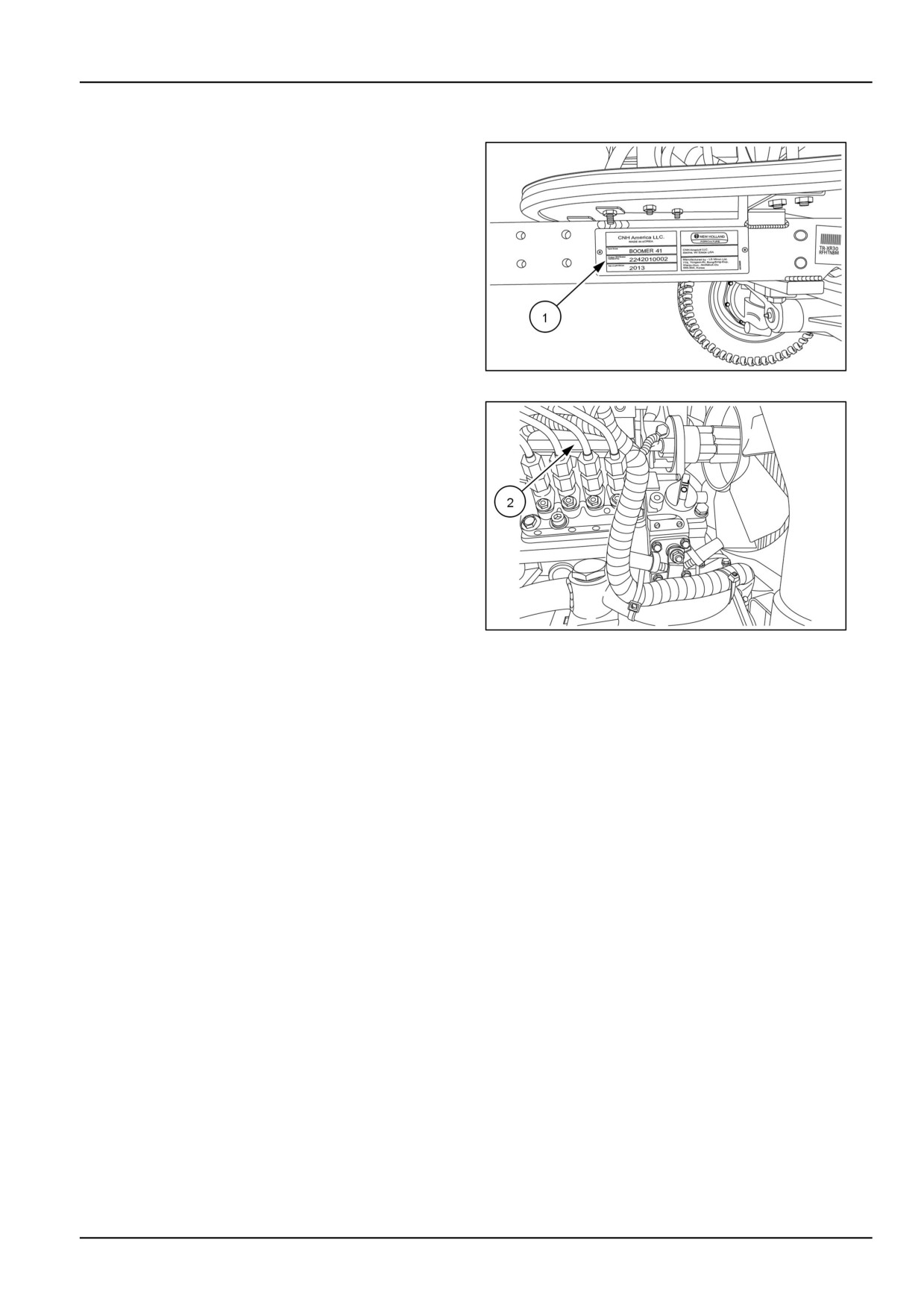
The Product Identification Plate (1) is located on the left-
hand side of the front frame..
The numbers on the plate are important in the event your
tractor should require future service.
NHIL13CT01348AA
1
The engine identification information plate (2) is located
on the right-hand side of the engine block, behind the fuel
injection pump.
NHIL13CT01118AA
2
1-5

1 - GENERAL INFORMATION
Operator's manual storage
The operator’s manual must be stored in a compartment
(1) located in the rear of the operator’s seat back and be
kept available for use by all operators.
NHIL13CT01163AA
1
1-6
1 - GENERAL INFORMATION
Machine orientation
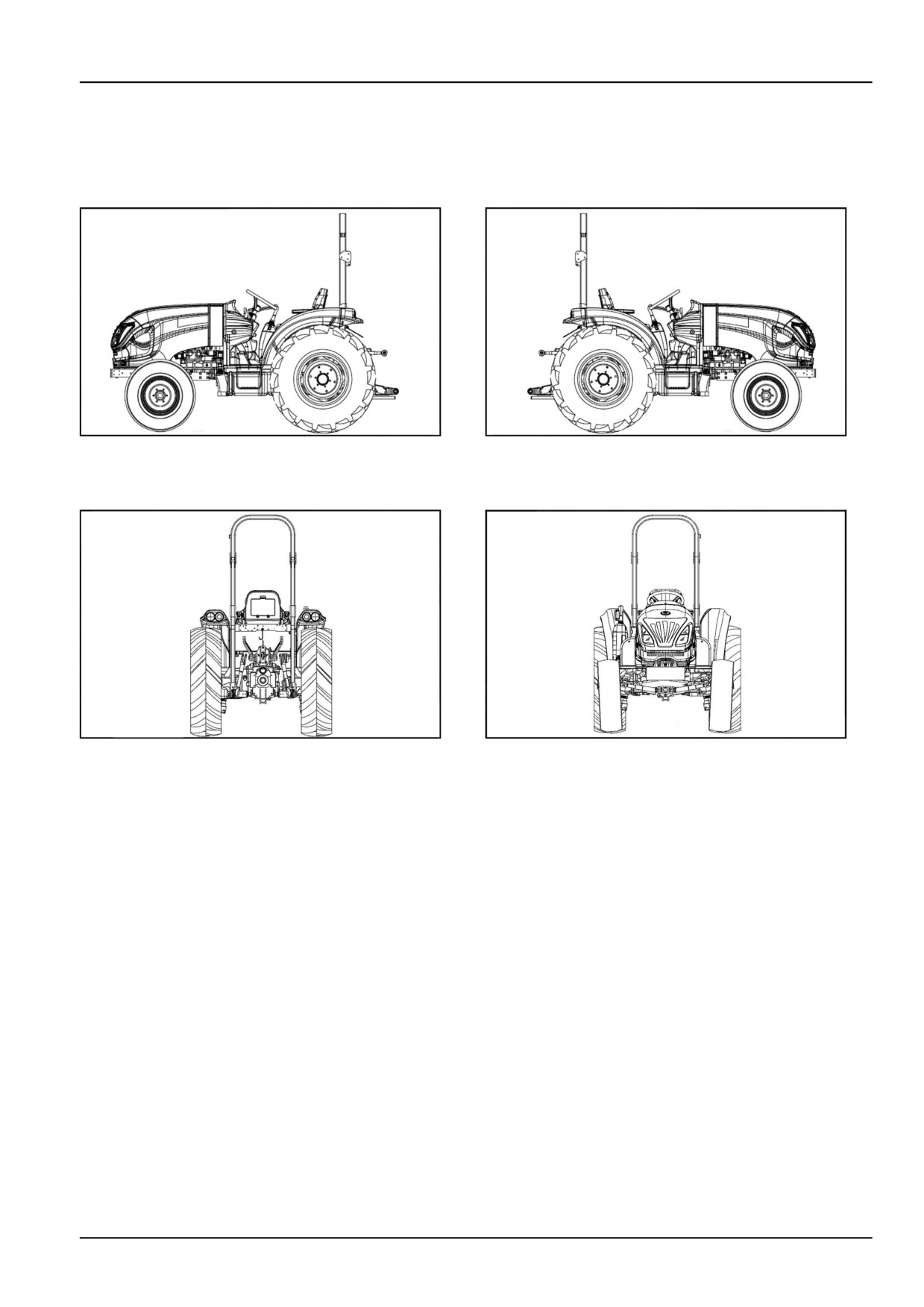
NOTE: On this equipment, left-hand and right-hand are
determined by standing behind the unit, looking in the di-
rection of travel.
NHIL13CT01187AA
1
NHIL13CT01188AA
2
Left-hand view
Right-hand view
NHIL13CT01186AA
3
NHIL13CT01345AA
4
Rear view
Front view
1-7

1 - GENERAL INFORMATION
Proposition 65
BT09A213
1
1-8
1 - GENERAL INFORMATION
Exhaust Gas Recirculation (EGR) - Diesel Particulate Filter (DPF)
exhaust treatment - Product overview
What is Exhaust Gas Recirculation (EGR)?
Your NEW HOLLAND machine is equipped with additional components to comply with national and local exhaust
emissions requirements. EGR works by recirculating a portion of the engine exhaust gasses back into the engine
combustion chamber to lower combustion temperatures.
The main components of the EGR system include:
• EGR valve
• Diesel Particulate Filter (DPF)
• Diesel Oxidation Catalyst (DOC)
• Exhaust gas temperature sensors
• Differential pressure sensor
• Throttle valve actuator
What is a Diesel Particulate Filter (DPF)?
A Diesel Particulate Filter (DPF) is a filter mounted in the exhaust stream. During normal operating conditions, the
exhaust gasses pass through the porous walls of the DPF and trap Particulate Matter (PM) generated by the com-
bustion process of the engine. When channels inside the (DPF) fill up with (PM), the system must be cleaned. The
cleaning process is called regeneration.
How does the regeneration process work?
When the (DPF) becomes restricted, the system will need to be cleaned or regenerated by raising exhaust temper-
atures to burn off the trapped Particulate Matter (PM). This process is usually done automatically. Burned PM will
leave behind traces of ash within the (DPF). The ash must be cleaned out by a NEW HOLLAND dealer outfitted with
machines specifically designed to clean (DPF) systems. See the [**Link to maintenance chart**] for service intervals.
Automatic regeneration
When the DPF enters automatic regeneration mode, the display will indicate “DPF ON”. Several conditions need to
be followed to properly let the machine perform this function.
• During this mode do not idle or shut the machine down.
• Hot exhaust gasses will be generated. Use in a well ventilated area away from combustible materials.
• Use the machine under normal work scenarios until the automatic regeneration process has completed.
Finding a Diesel Particulate Filter (DPF) cleaning facility
To find a NEW HOLLAND dealer that is fully equipped to service your DPF system, please call the number below.
New Holland Top Service: 1-866-639-4563
na.topservice@newholland.com
1-9
1 - GENERAL INFORMATION
FEDERAL EMISSIONS WARRANTY
WARRANTY STATEMENT
ISM warrants that your 2013 and later off-road diesel engine was designed, built and equipped to conform to
applicable U.S. Environmental Protection Agency (EPA) regulations and is free from defects in materials and
workmanship which cause it to fail to conform with such regulations, for the following period of operation:
• For a period of two (2) years or 1,500 hours of operation, whichever occurs first, after the date of delivery to the initial
retail owner of any variable speed off-road diesel engine rated at less than 19 kW (25 Hp) and any constant-speed
off-road diesel engine rated at less than 37 kW (50 Hp) with rated speed greater than or equal to 3,000 RPM.
• For a period of five (5) years or 3,000 hours of operation, whichever occurs first, after the date of delivery to the
initial retail owner for all other off-road diesel engines.
WARRANTY INFORMATION
The model year, class of diesel engine, and emission application for your engine are identified on the emission control
information label affixed to the right hand side of your engine’s front side of timing gear case or head cover.
Any emission control system parts that are proven defective during normal use will be repaired or replaced during
the warranty period. The warranty repairs and service will be performed by any authorized ISM dealer at the dealer’s
place of business, with no charge for parts or labor (including diagnosis).
As the engine owner, you are responsible to perform all the required maintenance listed in your owner’s manual. ISM
will not deny an emission warranty claim solely because you have no record of maintenance; however, a claim may
be denied if your failure to perform maintenance resulted in the failure of a warranted part. Receipts covering regular
maintenance should be retained in the event of questions and these receipts should be passed on to each subsequent
owner of the engine.
It is recommended that replacement parts used for maintenance or repairs be ISM Service Parts to maintain the quality
originally designed into your emission certified engine. The use of non-ISM parts does not invalidate the warranty on
other components unless the use of such parts causes damage to warranted parts.
ISM wishes to assure that the emission control systems warranty is being properly administered. If you believe you
have not received the service to which you are entitled to under this warranty, you should contact the nearest ISM
Branch Office for assistance. The address and phone number of each Branch Office is in your owner’s manual.
EXCEPTIONS
Please note that Emission Warranty does not cover:
5. Parts requiring replacement or inspection or adjust-
ment during scheduled maintenance intervals where
1. Systems and parts that were not first installed on the
the part is not defective.
new equipment or engine as original equipment by
ISM
6. Parts which are not ISM Service Parts.
2. Part malfunctions caused by abuse, misuse, im-
7. Loss of time, inconvenience, loss of use of equip-
proper adjustment, modification, alteration, tam-
ment/engine or commercial loss.
pering, disconnection, improper or inadequate
8. Equipment with an altered or disconnected hourme-
maintenance, or use of nonrecommended fuels and
ter where the hours cannot be determined.
lubricating oils.
9. Equipment normally operated outside the United
3. Damage caused by accident, acts of nature, or other
States
events beyond ISM’s control.
10. Non-defective parts replaced by other than ISM deal-
4. Replacement of expendable items made in connec-
ers.
tion with scheduled maintenance.
PARTS COVERED
This emission control system warranty applies to the
• Intake Manifold
following emission control parts:
• Exhaust Manifold
• Fuel Injection Pump
• Positive Crankcase Ventilation system parts (including
• Fuel Injectors
PCV Valve and Oil Filler Cap)
1-10
1 - GENERAL INFORMATION
• Turbocharger (if equipped)
• Intake throttle valve (if equipped)
• Charge air cooling system (if equipped)
• Exhaust Aftertreatment system (if equipped)
• Smoke puff limiter (if equipped)
• Aftertreatment Regeneration device (if equipped)
• EGR system (including EGR Valve, EGR Pipe and EGR
• Miscellaneous hoses, clamps, connectors and sealing
cooler) (if equipped)
gaskets or devices used in the above systems.
CALIFORNIA EMISSION CONTROL WARRANTY STATEMENT
California Air Resources Board (CARB)
YOUR WARRANTY RIGHTS AND OBLIGATIONS
The California Air Resources Board and ISM (ISM) are pleased to explain the emission control system warranty on
your 2013 and later engine. In California, new engines must be designed, built and equipped to meet the State’s
stringent anti-smog standards. ISM must warrant the emission control system on your engine for the periods of time
listed below provided there has been no abuse, neglect or improper maintenance of your engine. Additional conditions
and responsibilities are further outlined below. Where a warrantable condition exists, ISM will repair your engine at
no cost to you including diagnosis, parts and labor.
MANUFACTURER’S WARRANTY COVERAGE:
ISM warrants to the original owner, and to each subsequent owner, of a new, diesel engine that the emission
control system of your engine:
1. Was designed, built and equipped so as to conform at the time of sale with all applicable regulations of the Cali-
fornia Air Resources Board (CARB).
2. Is free from defects in material and workmanship that will cause such engine to fail to conform with applicable
regulations for the following warranty period:
• for variable speed engines rated under 19 kW (25 Hp): two (2) years or 1,500 hours of operation, whichever
occurs first. In the absence of a device to measure hours of use, the engine shall be warranted for a period of
two years.
• for constant speed engines rated under 37 kW (50 Hp) with peak power rated at 3,000 RPM or greater: two (2)
years or 1,500 hours of operation, whichever occurs first. In the absence of a device to measure hours of use,
the engine shall be warranted for a period of two years.
• for engines rated at or above 19 kW (25 Hp): five (5) years or 3,000 hours of operation, whichever occurs first.
In the absence of a device to measure hours of use, the engine shall be warranted for a period of five years.
• for engines rated at or above 37 kW (50 Hp): five (5) years or 3,000 hours of operation, whichever occurs first.
In the absence of a device to measure hours of use, the engine shall be warranted for a period of five years.
The warranty period shall begin:
• on the date the equipment is first delivered to the first retail purchaser, or;
• if the equipment is placed in service for demonstration purposes prior to sale at retail, on the date the engine is first
placed in service.
The emission control systems of your new ISM engine were designed, built and tested using genuine ISM parts, and
the engine is certified as being in conformity with CARB emission control regulations.
Accordingly, it is recommended that any replacement parts used for maintenance, repair or replacement of emission
control systems be ISM parts. Any replacement part may be used in the performance of any maintenance or repairs,
although ISM recommends that the owner obtain assurance that such parts are warranted by their manufacturer to
be equivalent to genuine ISM parts. Such use shall not reduce the warranty obligations of the engine manufacturer,
provided they are warranted to be equivalent to genuine ISM parts.
Any warranted part that is not scheduled for replacement, as required maintenance shall be warranted for the warranty
period defined above. If any such part fails during the period of warranty coverage, it will be repaired or replaced under
warranty. Any such part repaired or replaced under the warranty shall be warranted for the remaining warranty period.
1-11
1 - GENERAL INFORMATION
Any warranted part that is scheduled only for regular inspection in the written instructions shall be warranted for the
warranty period defined above. A statement in the written instructions to the effect of "repair or replace as neces-
sary" shall not reduce the period of warranty coverage. Any such part repaired or replaced under warranty shall be
warranted for the remaining warranty period.
Any warranted part that is scheduled for replacement, as required maintenance shall be warranted for the period of
time prior to the first scheduled replacement point for that part. If the part fails prior to the first scheduled replacement,
the part shall be repaired or replaced by the engine manufacturer under warranty. Any such part repaired or replaced
under warranty shall be warranted for the remainder of the period prior to the first scheduled replacement point for
the part.
Repair or replacement of any warranted part under warranty shall be performed at no charge to the owner at a war-
ranty station.
ISM provides warranty services or repairs at all manufacturer distribution centers (warranty stations) that are fran-
chised to service the subject engines. Please see the Customer Assistance section of this statement for help in
locating such service centers.
The owner will not be charged for diagnostic labor that leads to the determination that a warranted part is in fact
defective, provided that such diagnostic work is performed at a warranty station.
ISM is liable for damages to other engine components proximately caused by a failure under warranty of any war-
ranted part.
ISM is required by California regulations to maintain a supply of warranted parts sufficient to meet the expected de-
mand for such parts during the warranty period for the engines covered by this warranty.
OWNER’S WARRANTY RESPONSIBILITIES:
This engine is designed to operate on ultra-low sulfur diesel fuel only if rated >19kW, and on low sulfur or ultra-low
sulfur diesel fuel only if rated <19kW. Use of any other fuel may result in this engine no longer operating in compliance
with California’s emissions requirements.
The purchaser is responsible for initiating the warranty process. The California Air Resources Board suggests that
the engine be presented to an ISM dealer as soon as a problem exists. The warranty repairs should be completed by
the dealer as expeditiously as possible.
Add-on or modified parts, as defined in Section 1900(b)(1) and (b)(10), Title 13, that are not exempted by the Air
Resources Board may not be used. The use of any non-exempted add-on or modified parts shall be grounds for
disallowing a warranty claim made in accordance with this article. The engine manufacturer shall not be liable under
this article to warrant failures of warranted parts caused by the use of a non-exempted add-on or modified part.
The emissions control parts covered by this Emission Control System Warranty are listed under “What is Covered
By the Emission Warranty.” As the off-road engine owner, you are responsible for the performance of the required
maintenance listed in your owner's manual. ISM recommends that you retain all receipts covering maintenance on
your off-road engine, but ISM cannot deny warranty solely for the lack of receipts or for your failure to ensure the
performance of all scheduled maintenance.
As the off-road engine owner, you should however be aware that ISM may deny you warranty coverage if your off-road
engine or a part has failed due to abuse, neglect, improper maintenance or unapproved modifications.
Customer Assistance
In the event that you do not receive the warranty service to which you believe you are entitled under the Emission
Control System’s Warranty, you should contact ISM at the address below for assistance. If you need additional
assistance or information concerning the Emission Control System Warranty, contact:
IHI Shibaura Machinery Corporation
Quality department
1-1-1 Ishishiba , Matsumoto , Nagano,
390-8714 , Japan
Telephone: +81-263-25-4589
1-12
1 - GENERAL INFORMATION
What is Not Covered by the Emission Warranty
Please note that Emission Warranty does not cover:
5. Parts requiring replacement, inspection or adjust-
ment during scheduled maintenance intervals where
1. Systems and parts that were not first installed on the
the part is not defective.
new equipment or engine as original equipment by
ISM
6. Parts that are not ISM Service Parts.
2. Part malfunctions caused by abuse, misuse, im-
7. Loss of time, inconvenience, loss of use of equip-
proper adjustment, modification, alteration, tam-
ment/engine or commercial loss.
pering, disconnection, improper or inadequate
8. Equipment with an altered or disconnected hourme-
maintenance, or use of nonrecommended fuels and
ter where the hours cannot be determined. Equip-
lubricating oils.
ment normally operated outside the United States.
3. Damage caused by accident, acts of nature, or other
9. Non-defective parts replaced by other than ISM deal-
events beyond ISM’s control.
ers.
4. Replacement of expendable items made in connec-
tion with scheduled maintenance.
What is Covered by the Emission Warranty
The following is a list of systems and parts that are considered a part of the Emission Control System and are covered
by the Emission Warranty for engines that were built to conform to CARB regulations:
IMPORTANT! This may not include expendable maintenance items. Emission related parts requiring scheduled main-
tenance are warranted until their first scheduled replacement point only.
PARTS COVERED
This emission control system warranty applies to the
• Smoke puff limiter (if equipped)
following emission control parts.
• EGR system (including EGR Valve, EGR Pipe and EGR
• Fuel injection system
cooler) (if equipped)
• Intake manifold
• Intake throttle valve (if equipped)
• Exhaust manifold
• Exhaust aftertreatment system (if equipped)
• Positive crankcase ventilation system parts (including
• Aftertreatment Regeneration Device (if equipped)
PCV Valve and Oil Filler Cap)
• Miscellaneous hoses, clamps, connecters and sealing
• Turbocharger (if equipped)
gaskets or devices used in the above systems.
• Charge air cooling system (if equipped)
1-13
2 - SAFETY INFORMATION
2 - SAFETY INFORMATION###_2_###
Precautionary statements
Personal safety
This is the safety alert symbol. It is used to alert you to potential personal injury hazards. Obey all
safety messages that follow this symbol to avoid possible death or injury.
Throughout this manual and on machine safety signs, you will find the signal words DANGER, WARNING, and CAU-
TION followed by special instructions. These precautions are intended for the personal safety of you and those
working with you.
Read and understand all the safety messages in this manual before you operate or service the machine.
DANGER indicates a hazardous situation that, if not avoided, will result in death or serious injury. The color
associated with DANGER is RED.
WARNING indicates a hazardous situation that, if not avoided, could result in death or serious injury. The color
associated with WARNING is ORANGE.
CAUTION indicates a hazardous situation that, if not avoided, could result in minor or moderate injury. The
color associated with CAUTION is YELLOW.
FAILURE TO FOLLOW DANGER, WARNING, AND CAUTION MESSAGES COULD RESULT
IN DEATH OR SERIOUS INJURY.
Machine safety
NOTICE: Notice indicates a situation that, if not avoided, could result in machine damage or property damage. The
color associated with Notice is BLUE.
Throughout this manual you will find the signal word Notice followed by special instructions to prevent machine dam-
age or property damage. The word Notice is used to address practices not related to personal safety.
Information
NOTE: Note indicates additional information that clarifies steps, procedures, or other information in this manual.
Throughout this manual you will find the word Note followed by additional information about a step, procedure, or
other information in the manual. The word Note is not intended to address personal safety or property damage.
2-1
2 - SAFETY INFORMATION
Safety rules
General safety rules
Read this manual carefully before starting, using carrying
Do not alter the calibration of the pressure relief valves
out maintenance, refueling or performing any other type
in the various hydraulic circuits (steering, hydraulic lift,
of operation on the tractor.
auxiliary distributors, etc.).
Read all the safety decals on the tractor and follow the in-
Keep clear of moving parts. Loose clothing, jewelry,
structions thereon before starting, operating, refueling or
watches, long hair, and other loose or hanging items can
carrying out maintenance on the tractor. Promptly replace
become entangled in moving parts.
any decals that are damaged, lost or illegible. Clean the
decals if they are covered by mud or debris.
Wear protective equipment when appropriate.
The tractor must only be used by responsible personnel,
DO NOT attempt to remove material from any part of the
trained in tractor use and authorized to operate the tractor.
tractor while it is being operated or components are in
motion.
Use caution when operating the tractor on slopes. Raised
equipment, full tanks and other loads will change the cen-
Make sure all guards and shields are in good condition
ter of gravity of the tractor. The tractor can tip or roll
and properly installed before operating the tractor. Never
over when near ditches and embankments or uneven sur-
operate the tractor with shields removed. Always close
faces.
access doors or panels before operating the tractor.
Avoid using the tractor in unsuitable physical conditions,
Enter and leave the tractor using the steps and handles
stop work instead.
provided. Dirty or slippery steps, ladders, walkways, and
platforms can cause falls. Make sure these surfaces re-
Never permit anyone other than the operator to ride on
main clean and clear of debris.
the tractor.
A person or pet within the operating area of a tractor can
Never operate the tractor under the influence of alcohol,
be struck or crushed by the tractor or its equipment. DO
drugs, or while otherwise impaired.
NOT allow anyone to enter the work area.
When digging or using ground engaging attachments be
Raised equipment and/or loads can fall unexpectedly and
aware of buried cables. Contact local utilities to determine
crush persons underneath. Never allow anyone to enter
the locations of services.
the area underneath raised equipment during operation.
Pay attention to overhead power lines and hanging obsta-
Never operate engine in enclosed spaces as harmful ex-
cles. High voltage lines may require significant clearance
haust gases may build up.
for safety.
Before starting the tractor, be sure that all controls are in
Hydraulic oil or diesel fuel leaking under pressure can
neutral or park lock position.
penetrate the skin, causing serious injury or infection.
Before starting the engine, make sure that all attached
• DO NOT use your hand to check for leaks. Use a piece
implements are lowered to the ground.
of cardboard or paper.
Start the engine only from the operator’s seat. If the
• Stop engine, remove key and relieve the pressure be-
fore connecting or disconnecting fluid lines.
safety start switch is bypassed, the engine can start with
the transmission in gear. Do not connect or short across
• Make sure all components are in good condition and
terminals on the starter solenoid. Attach jumper cables
tighten all connections before starting the engine or
as described in the manual. Starting in gear may cause
pressurizing the system.
death or serious injury.
• If hydraulic fluid or diesel fuel penetrates the skin, seek
medical attention immediately.
Always keep windows, mirrors, all lighting, and Slow Mov-
ing Vehicle (SMV) emblem clean to provide the best pos-
• Continuous long term contact with hydraulic fluid may
sible visibility while operating the tractor.
cause skin cancer. Avoid long term contact and wash
the skin promptly with soap and water.
Operate controls only when seated in the operator’s seat,
• Before removing any hydraulic tubing, check that the
except for those controls expressly intended for use from
system is not pressurized.
other locations.
2-2
2 - SAFETY INFORMATION
Before leaving the tractor:
2.
Disengage all drive systems.
1. Park tractor on a firm level surface.
3.
WARNING
2. Put all controls in neutral or park lock position.
Some components may continue to run
down after disengaging drive systems.
3. Engage park brake. Use wheel chocks if required.
Make sure all drive systems are fully disen-
4. Lower all hydraulic equipment — Implements, header,
gaged.
etc.
Failure to comply could result in death or
5. Turn off engine and remove key.
serious injury.
W0113A
When, due to exceptional circumstances, you would
Shift the transmission into neutral.
decide to keep the engine running after leaving the
operator’s station, then the following precautions must
4.
Apply the parking brake.
be followed:
1. Bring the engine to low idle speed.
Using the tractor
1. Select the most suitable wheel setting for the work in
6. When using the brakes, press the pedal down slowly.
hand, i.e.: the setting that provides the best stability.
7. Avoid taking turns at high speeds.
2. Depress the speed control pedal slowly: if engaged
8. Always use the tractor at a speed that will guarantee
too quickly, especially when the tractor is getting out
safe operation on the type of land being worked.
of a hole, ditch or operating on muddy ground or
When working on uneven ground, use maximum
steep slopes, the tractor may overturn.
care to ensure proper stability.
Release the speed control pedal immediately if front
9. If you have to work with the tractor on a gradient,
wheels begin to lift.
for example on hillsides, drive at moderate speed
especially when taking turns.
3. When traveling downhill, keep the tractor in gear.
Never place shuttle shift lever in the neutral position.
10. Proceed with maximum caution when working with
the wheels near the edge of ditches or slopes.
4. When the tractor is moving, the operator must remain
correctly seated in the driving position.
11. When driving on public highways, observe the High-
way Code.
5. Never get on or off the tractor while in movement.
General maintenance safety
Keep area used for servicing the tractor clean and dry.
Jack or lift the tractor only at jack or lift points indicated in
Clean up spilled fluids.
this manual.
Service tractor on a firm level surface.
Incorrect towing procedures can cause accidents. When
towing a disabled tractor follow the procedure in this man-
Install guards and shields after servicing the tractor.
ual. Use only rigid tow bars.
Close all access doors and install all panels after servicing
Stop the engine, remove key and relieve pressure before
the tractor.
disconnecting or connecting fluid lines.
Do not attempt to clean, lubricate, clear obstructions or
Stop the engine and remove key before disconnecting or
make adjustments to the tractor while it is in motion or
connecting electrical connections.
while the engine is running.
Scalding can result from incorrect removal of coolant
Always make sure working area is clear of tools, parts,
caps. Cooling system operates under pressure. Hot
other persons and pets before you start operating the
coolant can spray out if a cap is removed while the
tractor.
system is hot. Allow system to cool before removing cap.
When removing a cap turn it slowly to allow pressure to
Unsupported hydraulic cylinders can lose pressure and
escape before completely removing the cap.
drop the equipment causing a crushing hazard. Do not
leave equipment in a raised position while parked or dur-
ing service, unless securely supported.
2-3
2 - SAFETY INFORMATION
Replace damaged or worn tubes, hoses, electrical wiring,
Always wash your hands after handling battery compo-
etc.
nents.
Engine, transmission, exhaust components, and hy-
Before touching any electrical components, disconnect
draulic lines may become hot during operation. Take
the ground lead from the battery.
care when servicing such components. Allow surfaces to
cool before handling or disconnecting hot components.
Only remove the radiator cap after the engine has been
Wear protective equipment when appropriate.
allowed to cool. With the engine switched off, use a cloth
to slowly unscrew the cap and release the pressure be-
When welding, follow the instructions in the manual. Al-
fore completely removing the cap.
ways disconnect the battery before welding on the tractor.
Wheels and tires
Upon receiving your tractor, check the air pressure in the
When changing or storing tires, make sure they are
tires and check every 50 hours or weekly. Refer to the
stacked correctly and cannot roll or topple over causing
table below for tire pressure for normal operation.
personal injury.
Make sure tires are correctly inflated. Do not exceed rec-
When checking tire pressures, inspect the tires for dam-
ommended load or pressure. Follow instructions in the
aged tread and side walls. Incorrect pressure will lead to
manual for proper tire inflation.
early tire failure.
Tires are heavy. Handling tires without proper equipment
Do not inflate a tire that has been run flat or seriously
could cause death or serious injury.
under-inflated until it has been inspected for damage by
a qualified person.
Never weld on a wheel with a tire installed. Always re-
move tire completely from wheel prior to welding.
Torque wheel bolts to specification after installing the
wheel. Check nut tightness daily until torque stabilizes.
Always have a qualified tire technician service the tires
and wheels. If a tire has lost all pressure, take the tire and
Refer to 'TRACTOR BALLASTING' section, Front
wheel to a tire shop or your dealer for service. Explosive
wheels - Ballast before adding ballast to the tires.
separation of the tire can cause serious injury.
Use jack stands or other suitable blocking to support the
DO NOT weld to a wheel or rim until the tire is completely
tractor while repairing tires. Ensure the jack is placed on a
removed. Ensure the rim is clean and free of rust or dam-
firm, level surface. Ensure the jack has adequate capacity
age. Do not weld, braze, otherwise repair or use a dam-
for lifting your tractor. Do not put any part of your body
aged rim. Inflated tires can generate a gas mixture with
under the tractor or start the engine while the tractor is on
the air that can be ignited by high temperatures from weld-
the jack.
ing procedures performed on the wheel or rim. Removing
the air or loosening the tire on the rim (breaking the bead)
Never hit a tire or rim with a hammer.
will NOT eliminate the hazard. This condition can exist
Do not inflate a tire unless the rim is mounted on the trac-
whether tires are inflated or deflated. The tire MUST be
tor or is secured so that it will not move if the tire or rim
completely removed from the wheel or rim prior to weld-
should suddenly fail.
ing the wheel or rim.
Driving on public roads and general transportation safety
Comply with local laws and regulations.
When transporting equipment or tractor on a transport
trailer, make sure it is properly secured. Be sure the SMV
Use appropriate lighting to meet local regulations.
on the equipment or tractor is covered while being trans-
ported on a trailer.
Make sure SMV emblem is visible.
Be aware of overhead structures or power lines and make
Make sure brake pedal latch is engaged. Brake pedals
sure the tractor and/or attachments can pass safely un-
must be locked together for road travel.
der.
Use safety chains for trailed equipment when provided
Travel speed should be such that complete control and
with tractor or equipment.
tractor stability is maintained at all times.
Lift implements and attachments high enough above
Slow down and signal before turning.
ground to prevent accidental contact with road.
Pull over to allow faster traffic to pass.
2-4
2 - SAFETY INFORMATION
Follow correct towing procedure for equipment with or When driving, do not rest your feet on the brake pedals.
without brakes.
Towing
1. To guarantee tractor stability when moving, adjust the
lower arms or the top link of the three-point linkage.
hitching device according to the trailer or implement to
This may result in tipping or overturning
be used.
5. When towing, do not negotiate turns with the differen-
2. Drive slowly when towing extremely heavy loads.
tial lock engaged as this may prevent you from steer-
ing the tractor.
3. Do not tow trailers that are not fitted with an indepen-
dent braking system.
4. If the tractor is used to tow heavy loads, always use
the hitching device and never hitch loads onto the
2-5
2 - SAFETY INFORMATION
Using implements and agricultural machinery
1. Do not connect implements or machinery that require
lever in the neutral position, apply the hand brake and
more power than can be generated by your tractor
use suitable wheel chocks.
model.
5. Do not operate tractors connected to the power take-
2. Never negotiate sharp turns with the power take-off
off without first ensuring that the operating range of
under a heavy load; this may damage the univer-
the tractor is free of bystanders. Also check that all
sal joints on the transmission shaft connected to the
rotating parts connected to the power take-off shaft
power take-off.
are correctly protected.
3. Never stand between the reversing tractor and the im-
6. Add some type of rear ballast when using lifting equip-
plement when hitching.
ment fitted to the front of the tractor. Rear ballast, such
as, rear wheel weights, fluid in rear tires or three-point
4. When using implements that require the tractor to be
weight box.
stationary with the engine running, keep the shuttle
Fire and explosion prevention
Fuel or oil leaked or spilled on hot surfaces or electrical
belts, gears, cleaning fan, etc. More frequent cleaning
components can cause a fire.
of your tractor may be necessary depending on the
operating environment and conditions.
Crop materials, trash, debris, bird nests, or flammable
material can ignite on hot surfaces.
Inspect the electrical system for loose connections or
frayed insulation. Repair or replace loose or damaged
Always have a fire extinguisher on or near the tractor.
parts.
Make sure the fire extinguisher(s) is maintained and ser-
Do not store oily rags or other flammable material on the
viced according to the manufacturer’s instructions.
tractor.
At least once each day and at the end of the day remove
Do not weld or flame cut any items that contain flammable
all trash and debris from the tractor especially around hot
material. Clean items thoroughly with non-flammable sol-
components such as engine, transmission, exhaust, bat-
vents before welding or flame-cutting.
tery, etc. More frequent cleaning of your tractor may be
necessary depending on the operating environment and
Do not expose the tractor to flames, burning brush, or
conditions.
explosives.
At least once each day, remove debris accumulation
Promptly investigate any unusual smells or odors that
around moving components such as bearings, pulleys,
may occur during operation of the tractor.
General battery safety
Always wear eye protection when working with batteries.
Follow manufacturer’s instructions when storing and han-
dling batteries.
Do not create sparks or have open flame near battery.
Battery post, terminals, and related accessories contain
Ventilate when charging or using in an enclosed area.
lead and lead compounds. Wash hands after handling.
This is a California Proposition 65 warning.
Disconnect negative (-) first and reconnect negative (-)
last.
Battery acid causes burns. Batteries contain sulfuric acid.
Avoid contact with skin, eyes, or clothing. Antidote (exter-
When welding on the tractor, disconnect both terminals of
nal): Flush with water. Antidote (eyes): flush with water
the battery.
for 15 minutes and seek medical attention immediately.
Antidote (internal): Drink large quantities of water or milk.
Do not weld, grind, or smoke near a battery.
Do not induce vomiting. Seek medical attention immedi-
ately.
When using auxiliary batteries or connecting jumper ca-
bles to start the engine, use the procedure shown in the
Keep out of reach of children and other unauthorized per-
operator’s manual. Do not short across terminals.
sons.
Operator presence system
Your tractor is equipped with an operator presence sys-
The operator presence system should never be discon-
tem to prevent the use of some features while the operator
nected or bypassed.
is not in the operator’s seat.
2-6
2 - SAFETY INFORMATION
If the system is inoperable, the system must be repaired.
Power Take-Off (PTO)
PTO-driven machinery can cause death or serious injury.
•
Match the right tractor PTO spline and speed with the
Before working on or near the PTO shaft or servicing or
PTO driveshaft provided with an implement. This will
clearing the driven tractor, put the PTO lever in the disen-
assure proper geometry and operating speed.
gage position, stop the engine, and remove the key.
•
Never operate 540 RPM implements at 1000 RPM.
Whenever a PTO is in operation, a guard must be in place
•
Never operate 1000 RPM implements at 540 RPM.
to prevent death or injury to the operator or bystanders.
•
Use of PTO adapters will void the warranty of the drive
shaft, and the PTO drive train of the machine and im-
When doing stationary PTO work, keep clear of all moving
plement.
parts and make sure appropriate guards are in place.
•
For correct hitch geometry, see the implement opera-
Never use a spline adapter:
tor’s manual.
Reflectors and warning lights
Flashing amber warning lights must be used when oper-
ating on public roads. Location and use of flashing amber
warning lights is shown on Cab controls - Control.
Seat belts
Seat belts must be worn at all times.
•
Check that bolts are tight on the seat bracket or mount-
ing.
Seat belt inspection and maintenance:
•
If belt is attached to seat, make sure seat or seat brack-
• Keep seat belts in good condition.
ets are mounted securely.
• Keep sharp edges and items than can cause damage
•
Keep seat belts clean and dry.
away from the belts.
•
Clean belts only with soap solution and warm water.
• Periodically check belts, buckles, retractors, tethers,
•
Do not use bleach or dye on the belts because this can
slack take-up system, and mounting bolts for damage
make the belts weak.
and wear.
•
For proper seat belt use, see Seat restraints - Oper-
• Replace all parts that have damage or wear.
ating.
• Replace belts that have cuts that can make the belt
weak.
2-7
2 - SAFETY INFORMATION
Operator protective structure
Your tractor is equipped with an operator protective struc-
After an accident, fire, tip or roll over, the following MUST
ture, such as: a Roll Over Protective Structure (ROPS),
be performed by a qualified technician before returning
Falling Object Protective Structure (FOPS), or a cab with
the tractor to field or job-site operations:
ROPS. A ROPS may be a can frame or a two-posted or
• The protective structure MUST BE REPLACED.
four-posted structure used for the protection of the op-
erator to minimize the possibility of serious injury. The
• The mounting or suspension for the protective struc-
mounting structure and fasteners forming the mounting
ture, operator seat and suspension, seat belts and
connection with the tractor are part of the ROPS.
mounting components, and wiring within the operator’s
protective system MUST be carefully inspected for
The protective structure is a special safety component of
damage.
your tractor.
• All damaged parts MUST BE REPLACED.
DO NOT attach any device to the protective structure for
DO NOT WELD, DRILL HOLES, ATTEMPT TO
pulling purposes. DO NOT drill holes to the protective
STRAIGHTEN, OR REPAIR THE PROTECTIVE STRUC-
structure.
TURE. MODIFICATION IN ANY WAY CAN REDUCE
THE STRUCTURAL INTEGRITY OF THE STRUCTURE,
The protective structure and interconnecting components
WHICH COULD CAUSE DEATH OR SERIOUS INJURY
are a certified system. Any damage, fire, corrosion, or
IN THE EVENT OF FIRE, TIP, ROLL OVER, COLLISION,
modification will weaken the structure and reduce your
OR ACCIDENT.
protection. If this occurs, THE PROTECTIVE STRUC-
TURE MUST BE REPLACED so that it will provide the
Seat belts are part of your protective system and must be
same protection as a new protective structure. Contact
worn at all times. The operator must be held to the seat
your dealer for protective structure inspection and re-
inside the frame in order for the protective system to work.
placement.
2-8
2 - SAFETY INFORMATION
Personal Protective Equipment (PPE)
Wear Personal Protective Equipment (PPE) such as hard
hat, eye protection, heavy gloves, hearing protection, pro-
tective clothing, etc.
Do Not Operate tag
Before you start servicing the tractor, attach a ‘Do Not
Operate’ warning tag to the tractor in an area that will be
visible.
Hazardous chemicals
If you are exposed to or come in contact with hazardous
Dispose of all fluids, filters, and containers in an environ-
chemicals you can be seriously injured. The fluids, lu-
mentally safe manner according to local laws and regula-
bricants, paints, adhesives, coolant, etc. required for the
tions. Check with local environmental and recycling cen-
function of your tractor can be hazardous. They may be
ters or your dealer for correct disposal information.
attractive and harmful to domestic animals as well as hu-
mans.
Store fluids and filters in accordance with local laws and
regulations. Use only appropriate containers for the stor-
Material Safety Data Sheets (MSDS) provide information
age of chemicals or petrochemical substances.
about the chemical substances within a product, safe
handling and storage procedures, first aid measures and
Keep out of reach or children or other unauthorized per-
procedures to be taken in the event of a spill or accidental
sons.
release. MSDS are available from your dealer.
Additional precautions are required for applied chemi-
Before you service your tractor check the MSDS for each
cals. Obtain complete information from the manufacturer
lubricant, fluid, etc. used in this tractor. This information
or distributor of the chemicals before using them.
indicates the associated risks and will help you service
the tractor safely. Follow the information in the MSDS, on
manufacturer containers, as well as the information in this
manual when servicing the tractor.
Utility safety
When digging or using ground-engaging equipment, be
power source occur, the following precautions must be
aware of buried cables and other services. Contact your
taken:
local utilities or authorities, as appropriate to determine
• Stop the tractor movement immediately.
the locations of services.
• Apply the park brake, stop the engine, and remove the
Make sure the tractor has sufficient clearance to pass in
key.
all directions. Pay special attention to overhead power
• Check if you can safely leave the cab or your actual
lines and hanging obstacles. High voltage lines may re-
position without contact with electrical wires. If not, stay
quire significant clearance for safety. Contact local au-
in your position and call for help. If you can leave your
thorities or utilities to obtain safe clearance distances from
position without touching lines, jump clear of the tractor
high voltage power lines.
to make sure you do not make contact with the ground
and the tractor at the same time.
Retract raised or extended components, if necessary.
Remove or lower radio antennas or other accessories.
• Do not permit anyone to touch the tractor until power
Should a contact between the tractor and an electric
has been shut off to the power lines.
2-9
2 - SAFETY INFORMATION
Electrical storm safety
Do not operate tractor during an electrical storm.
If an electrical storm should strike during operation, re-
main in the cab. Do not leave the cab or operator’s plat-
If you are on the ground during an electrical storm, stay
form. Do not make contact with the ground or objects
away from machinery and equipment. Seek shelter in a
outside the tractor.
permanent, protected structure.
Mounting and dismounting
Mount and dismount the tractor only at designated loca-
Maintain a three-point contact with steps, ladders, and
tions that have handholds, steps, or ladders.
handholds.
Do not jump off the tractor.
Never mount or dismount from a moving tractor.
Make sure steps, ladders, and platforms remain clean
Do not use the steering wheel or other controls or acces-
and clear of debris and foreign substances. Injury may
sories as handholds when entering or exiting the cab or
result from slippery surfaces.
operator’s platform.
Face the tractor when mounting and dismounting.
Working at heights
When the normal use and maintenance of the tractor
• Do not stand on surfaces which are not designated as
requires working at heights:
steps or platforms.
• Correctly use installed steps, ladders, and railings.
Do not use the tractor as a lift, ladder, or platform for work-
• Never use ladders, steps, or railings while the tractor is
ing at heights.
moving.
Lifting and overhead loads
Never use loader buckets, forks, etc. or other lifting, han-
Loader buckets, forks, etc. or other lifting, handling, or
dling, or digging equipment to lift persons.
digging equipment and its load will change the center of
gravity of the tractor. This can cause the tractor to tip on
Do not use raised equipment as a work platform.
slopes or uneven ground.
Know the full area of movement of the tractor and equip-
Load items can fall off the loader bucket or lifting equip-
ment and do not enter or permit anyone to enter the area
ment and crush the operator. Care must be taken when
of movement while the tractor is in operation.
lifting a load. Use proper lifting equipment.
Never enter or permit anyone to enter the area under-
Do not lift load higher than necessary. Lower loads to
neath raised equipment. Equipment and/or loads can fall
transport. Remember to leave appropriate clearance to
unexpectedly and crush persons underneath it.
the ground and other obstacles.
Do not leave equipment in raised position while parked
Equipment and associated loads can block visibility and
or during service, unless securely supported. Hydraulic
cause an accident. Do not operate with insufficient visi-
cylinders must be mechanically locked or supported if
bility.
they are left in a raised position for service or access.
2-10
2 - SAFETY INFORMATION
Do not operate tag
WARNING
Moving parts!
Disengage the Power Take-Off (PTO), turn off
the engine, and remove the key. Wait for all
movement to stop before leaving the opera-
tor's position. Never adjust, lubricate, clean,
or unplug machine with the engine running.
Failure to comply could result in death or se-
rious injury.
W0112A
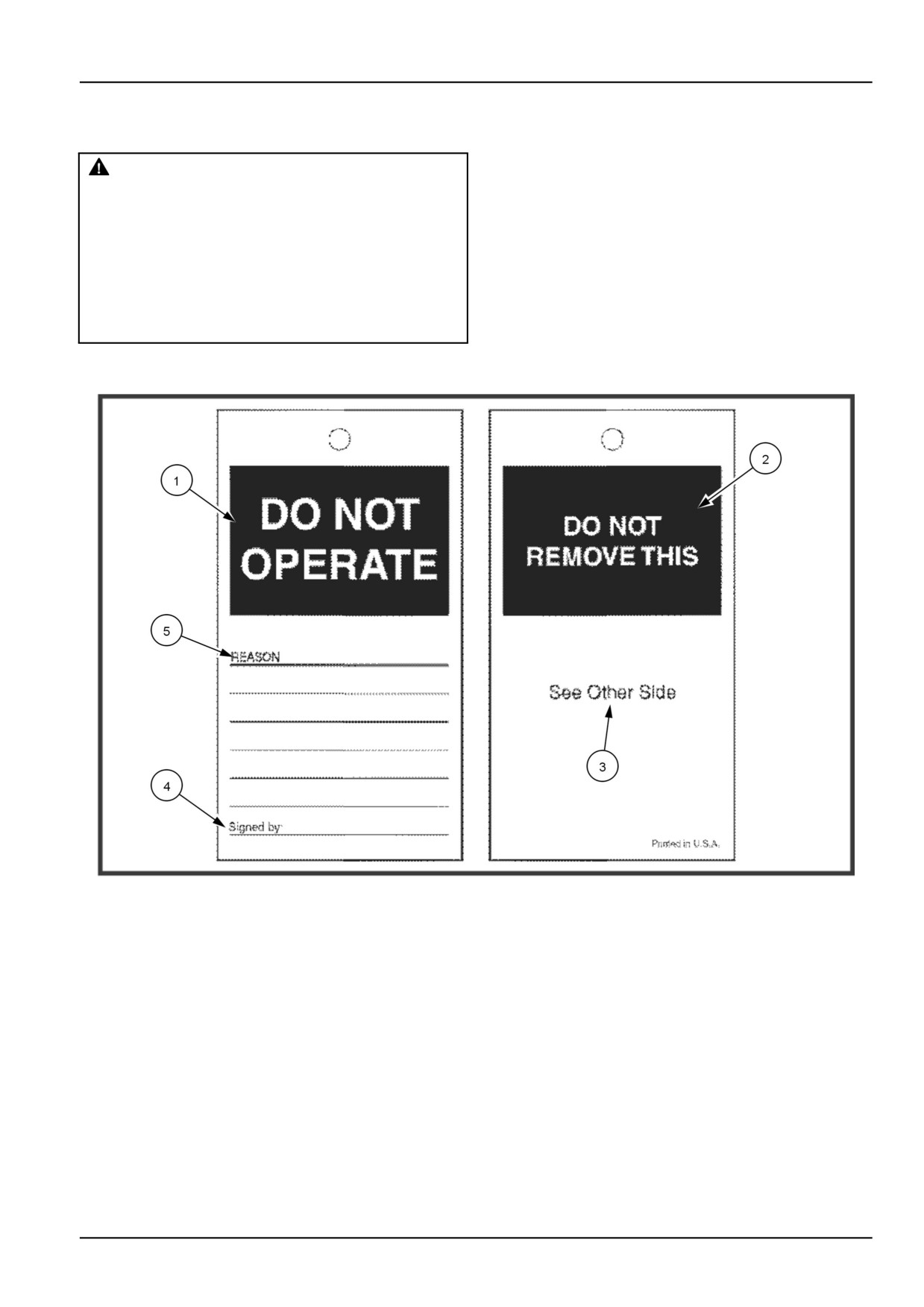
Before you service the machine, put a DO NOT OPERATE tag on the instrument panel.
321_4614
1
DO NOT OPERATE TAG
A.
(1) Do not operate.
B.
(2) Do not remove this.
C. (3) See other side.
D. (4) Signed by.
E.
(5) Reason
The DO NOT OPERATE tag can be obtained from your NEW HOLLAND dealer.
2-11
2 - SAFETY INFORMATION
Roll Over Protective Structure (ROPS)
The protective structure and interconnecting components
are a certified system. Any damage, fire, corrosion,
WARNING
or modification will weaken the structure and reduce
Misuse hazard!
your protection. If this occurs, the PROTECTIVE
Your machine is equipped with an operator
STRUCTURE MUST BE REPLACED so that it will
protective structure. DO NOT weld, drill holes,
provide the same protection as a new protective
attempt to straighten, or repair the protective
structure. Contact your dealer for protective structure
structure. Modification in any way can reduce
inspection and replacement.
the structural integrity of the structure.
Failure to comply could result in death or se-
After an accident, fire, and tip- or roll-over, the following
rious injury.
W0001B
MUST be performed by a qualified technician before
returning the machine to field or job site operation:
Your machine is equipped with an operator protective
structure, such as a Rollover Protective Structure
• The protective structure MUST BE REPLACED.
(ROPS), Falling Object Protective Structure (FOPS), or
• The mounting or suspension for the protective struc-
cab with ROPS. The protective structure is a special
ture, operator seat and suspension, seat belts and
safety component of your machine.
mounting components, and wiring within the operator's
protective system MUST be carefully inspected for
A ROPS may be a cab frame or a two-posted or
damage.
four-posted structure used for the protection of the
operator to minimize the possibility of serious injury. The
• All damaged parts MUST BE REPLACED.
mounting structure and fasteners forming the mounting
DO NOT WELD, DRILL HOLES, ATTEMPT TO
connection with the machine are part of the ROPS. The
STRAIGHTEN, OR REPAIR THE PROTECTIVE STRUC-
seat belt is an integral part of the ROPS.
TURE. MODIFICATION IN ANY WAY CAN REDUCE
THE STRUCTURAL INTEGRITY OF THE STRUCTURE,
DO NOT attach any device to the protective structure for
WHICH COULD CAUSE DEATH OR SERIOUS INJURY
pulling purposes. DO NOT drill holes in the protective
IN THE EVENT OF A FIRE, TIP, ROLLOVER, COLLI-
structure.
SION, OR ACCIDENT.
2-12
2 - SAFETY INFORMATION
Ecology and the environment
Soil, air, and water are vital factors of agriculture and life in general. When legislation does not yet rule the treatment
of some of the substances which are required by advanced technology, common sense should govern the use and
disposal of products of a chemical and petrochemical nature.
NOTICE: The following are recommendations which may
be of assistance:
• Become acquainted with and ensure that you understand the relative legislation applicable to your country.
• Where no legislation exists, obtain information from suppliers of oils, filters, batteries, fuels, antifreeze, cleaning
agents, etc., with regard to their effect on man and nature and how to safely store, use and dispose of these sub-
stances.
• Agricultural consultants will, in many cases, be able to help you as well.
HELPFUL HINTS
• Avoid filling tanks using cans or inappropriate pressurized fuel delivery systems which may cause considerable
spillage.
• In general, avoid skin contact with all fuels, oils, acids, solvents, etc. Most of them contain substances which may
be harmful to your health.
• Modern oils contain additives. Do not burn contaminated fuels and or waste oils in ordinary heating systems.
• Avoid spillage when draining off used engine coolant mixtures, engine, gearbox and hydraulic oils, brake fluids, etc.
Do not mix drained brake fluids or fuels with lubricants. Store them safely until they can be disposed of in a proper
way to comply with local legislation and available resources.
• Modern coolant mixtures, i.e. antifreeze and other additives, should be replaced every two years. They should not
be allowed to get into the soil but should be collected and disposed of properly.
• Do not open the air-conditioning system yourself. It contains gases which should not be released into the atmos-
phere. Your NEW HOLLAND dealer or air conditioning specialist has a special extractor for this purpose and will
have to recharge the system properly.
• Repair any leaks or defects in the engine cooling or hydraulic system immediately.
• Do not increase the pressure in a pressurized circuit as this may lead to a component failure.
• Protect hoses during welding as penetrating weld splatter may burn a hole or weaken them, allowing the loss of
oils, coolant, etc.
2-13
2 - SAFETY INFORMATION
Safety signs
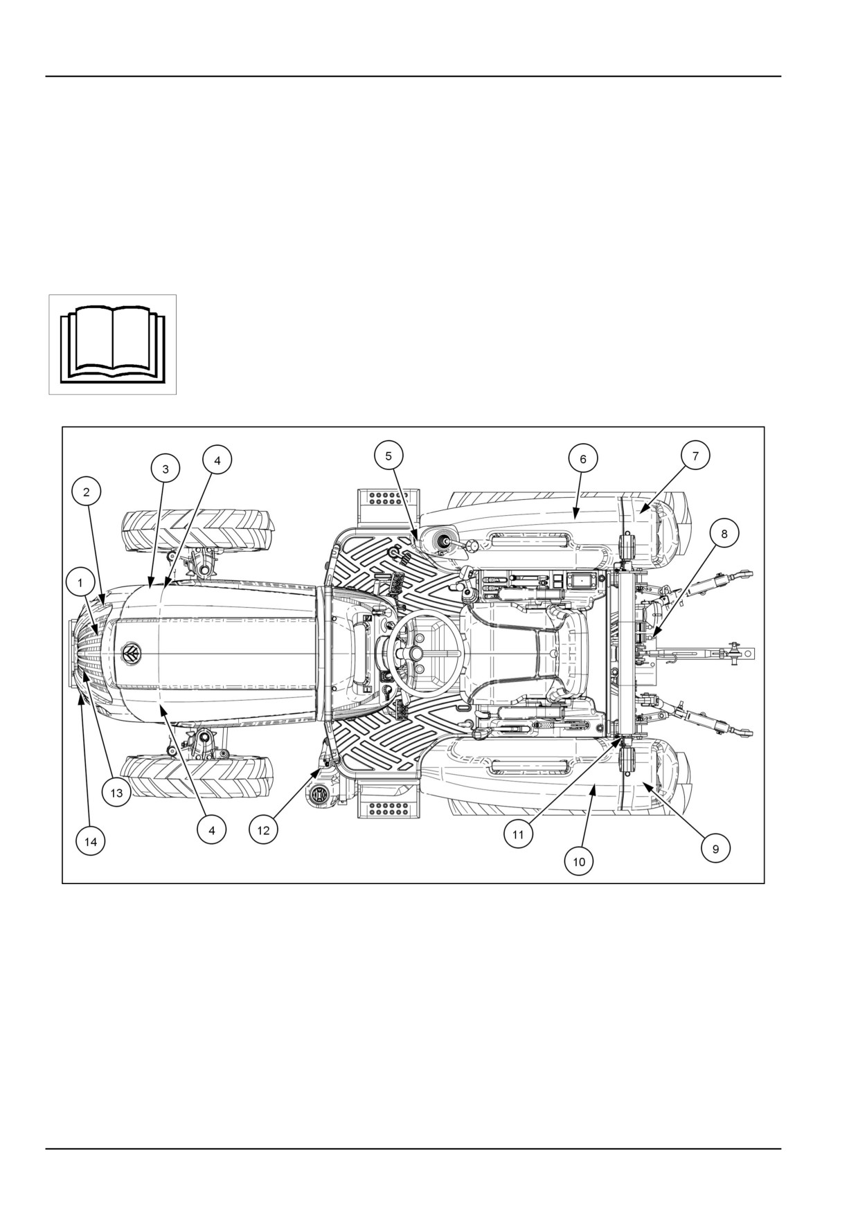
The following safety signs are placed on your machine as a guide for your safety and for those working with you. Walk
around the machine and note the content and location of these safety signs before operating your machine.
Keep safety signs clean and legible. Clean safety signs with a soft cloth, water, and a gentle detergent. Do not use
solvent, gasoline, or other harsh chemicals. Solvents, gasoline, and other harsh chemicals may damage or remove
safety signs.
Replace all safety signs that are damaged, missing, painted over, or illegible. If a safety sign is on a part that is
replaced, make sure the safety sign is installed on the new part. See your dealer for replacement safety signs.
Safety signs that display the “Read Operator’s Manual” symbol are intended to direct
the operator to the operator’s manual for further information regarding maintenance,
adjustments, or procedures for particular areas of the machine. When a safety sign
displays this symbol, refer to the appropriate page of the operator’s manual.
NHIL13CT01199FA
1
2-14
2 - SAFETY INFORMATION
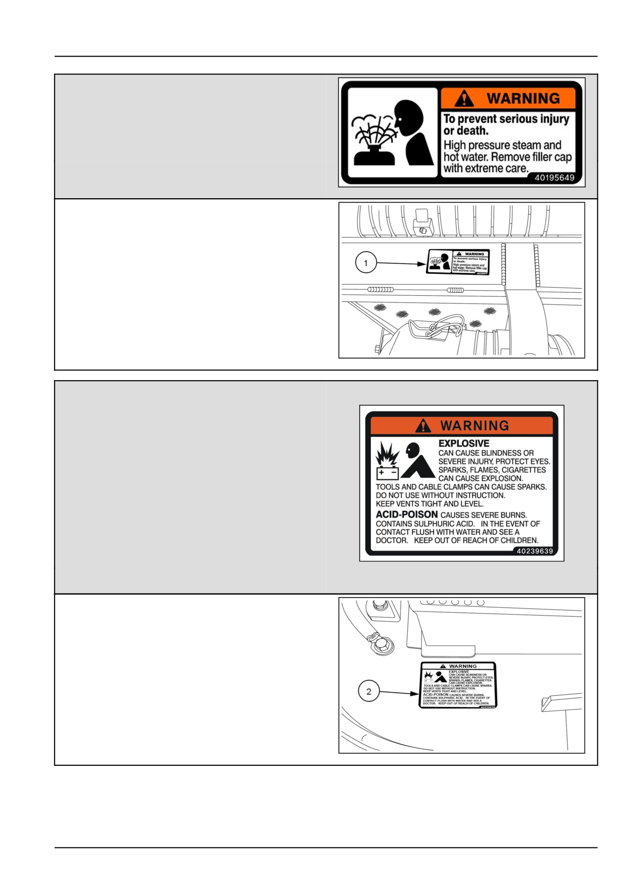
(1)
WARNING
To prevent serious injury or death.
High pressure steam and hot water.
Remove filler cap with extreme care.
Failure to comply could result in death or serious
injury.
Quantity: 1
English Part Number: MT40195649
40195649
2
(1) Location: On top of screen frame.
NHIL13CT00990AA
3
(2)
WARNING
EXPLOSIVE
Can cause blindness or severe injury, protect eyes.
Sparks, flames, cigarettes can cause explosion.
Tools and cable clamps can cause sparks. Do not
use without instruction. Keep vents tight and level.
ACID-POISON causes severe burns. Contains
sulphuric acid. In the event of contact flush with
water and see a doctor. Keep out of reach of children.
Failure to comply could result in death or serious
injury.
•
40239639
4
Quantity: 1
English Part Number: MT40239639
(2) Location: On the right front edge of the battery tray.
NHIL13CT00991AA
5
2-15
2 - SAFETY INFORMATION
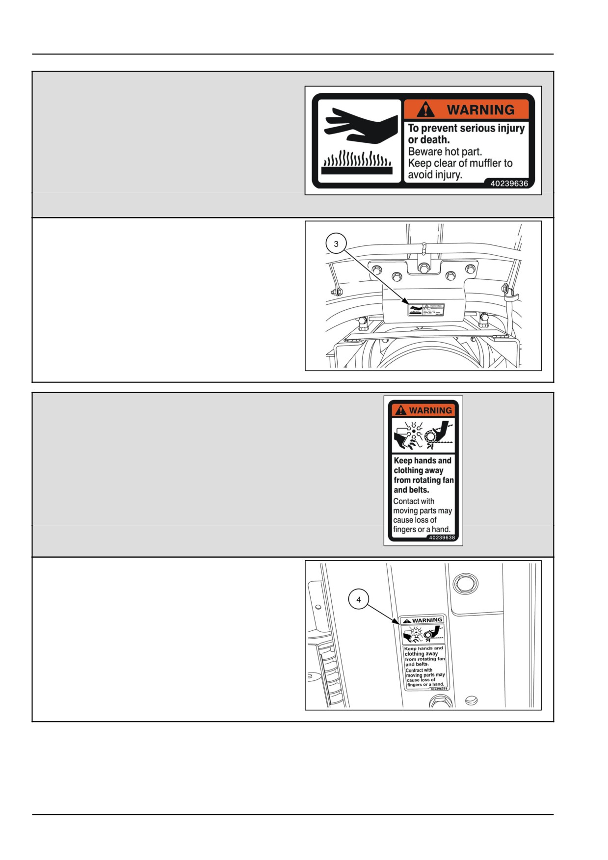
(3)
WARNING
To prevent serious injury or death.
Beware hot part.
Keep clear of muffler to avoid injury.
Failure to comply could result in minor or moderate
injury.
•
Quantity: 1
40239636
6
English Part Number: MT40239636
(3) Location: Under the hood, on top of the differential
pressure sensor.
NHIL13CT01213AA
7
(4)
WARNING
Keep hands and clothing away from the rotating fan
and belts.
Contact with moving parts may cause loss of fingers
or a hand.
Failure to comply could result in death or serious
injury.
•
Quantity: 2
English Part Number: MT40239638
40239638
8
(4) Location : On the left-hand and right-hand sides of
the fan shroud.
NHIL13CT00989AA
9
2-16
2 - SAFETY INFORMATION
(5)
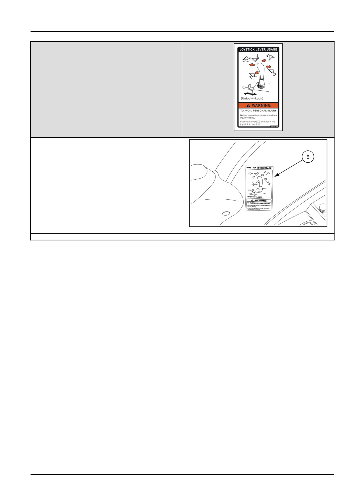
JOYSTICK LEVER USAGE
WARNING
To avoid personal injury:
Wrong operation causes serious injury easily.
Push the lever (1) in to lock the joystick in neutral.
Failure to comply could result in death or serious
injury.
Quantity: 1
English Part Number: MT40194109
40194109
10
(5) Location: On the right-hand fender.
NHIL13CT01035AA
11
2-17
2 - SAFETY INFORMATION
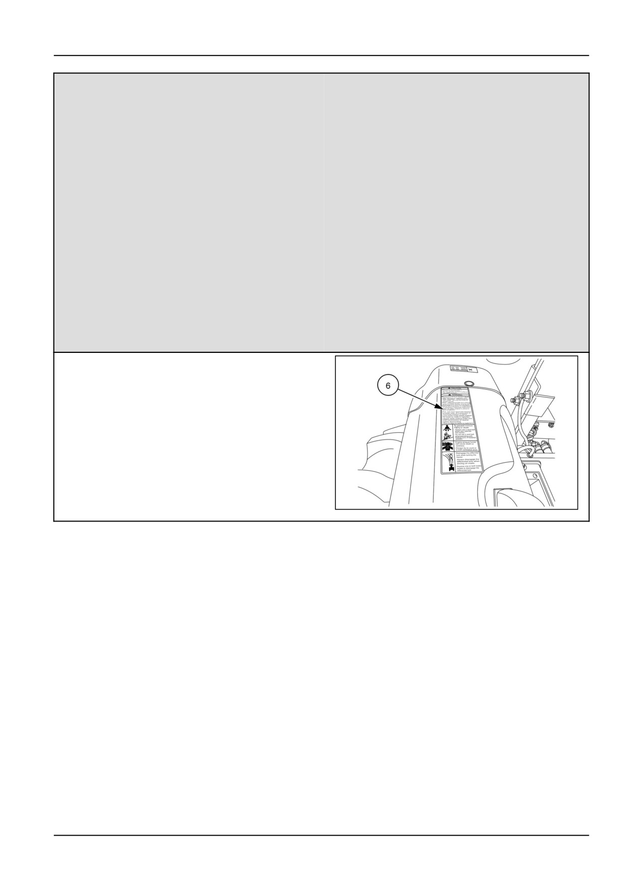
(6)
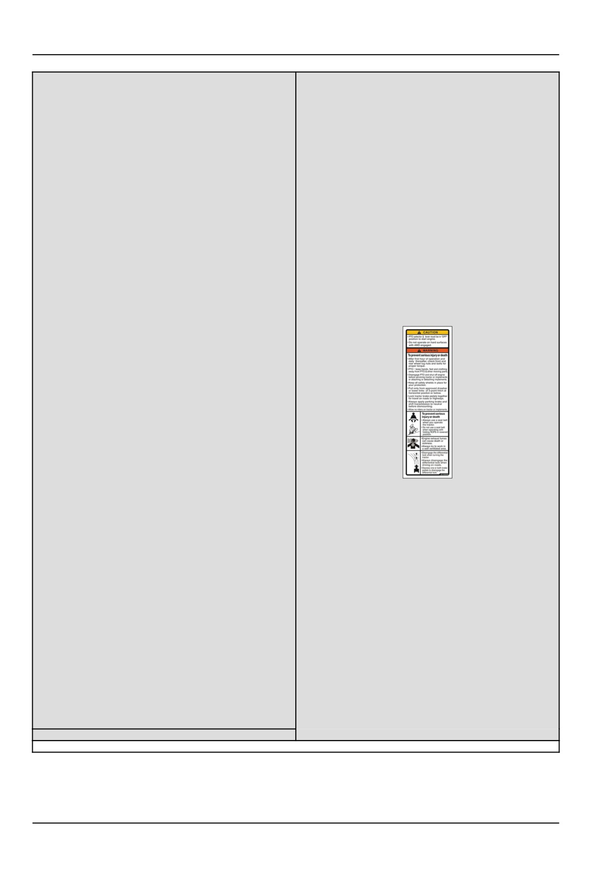
Multiple Safety Cautions and Warnings
CAUTION
•
PTO selector & lever must be in the “OFF” position
to start engine.
•
Do not operate on hard surfaces with 4WD engaged.
WARNING
To prevent serious injury or death:
•
After first hour of operation and daily thereafter,
check front and rear wheel lug nuts and bolts for
proper torque.
•
PTO-keep hands. feet and clothing away from PTO
& other moving parts.
•
Disengage PTO and shut off engine before servic-
ing tractor or implements or attaching or detaching
implements.
•
Keep all safety shields in place for your protection.
•
40195656
12
Pull only from approved drawbar or lower links of
3-point hitch at horizontal position or below.
•
Lock tractor brake pedals together for travel on
roads or highways.
•
Always apply parking brake and shift transmission
to neutral before dismounting.
•
Always use a seat belt when you operate the tractor.
•
Allow no riders on tractor or implements.
•
Always use a seat belt when you operate the tractor.
2-18
2 - SAFETY INFORMATION
•
Do not use a seat belt when operating with folding
ROPS in lowered position.
•
Engine exhaust fumes can cause death or sickness.
Always try to work in a well ventilated area.
•
Disengage the differential lock when turning the
tractor. Always disengage the differential lock when
driving on roads.
•
Depress one or both brake pedals to disengage the
differential lock.
Failure to comply could result in death or serious
injury.
Quantity: 1
English Part Number: MT40195656
(6) Location: On the top of the right-hand fender.
NHIL13CT01200AA
13
2-19
2 - SAFETY INFORMATION
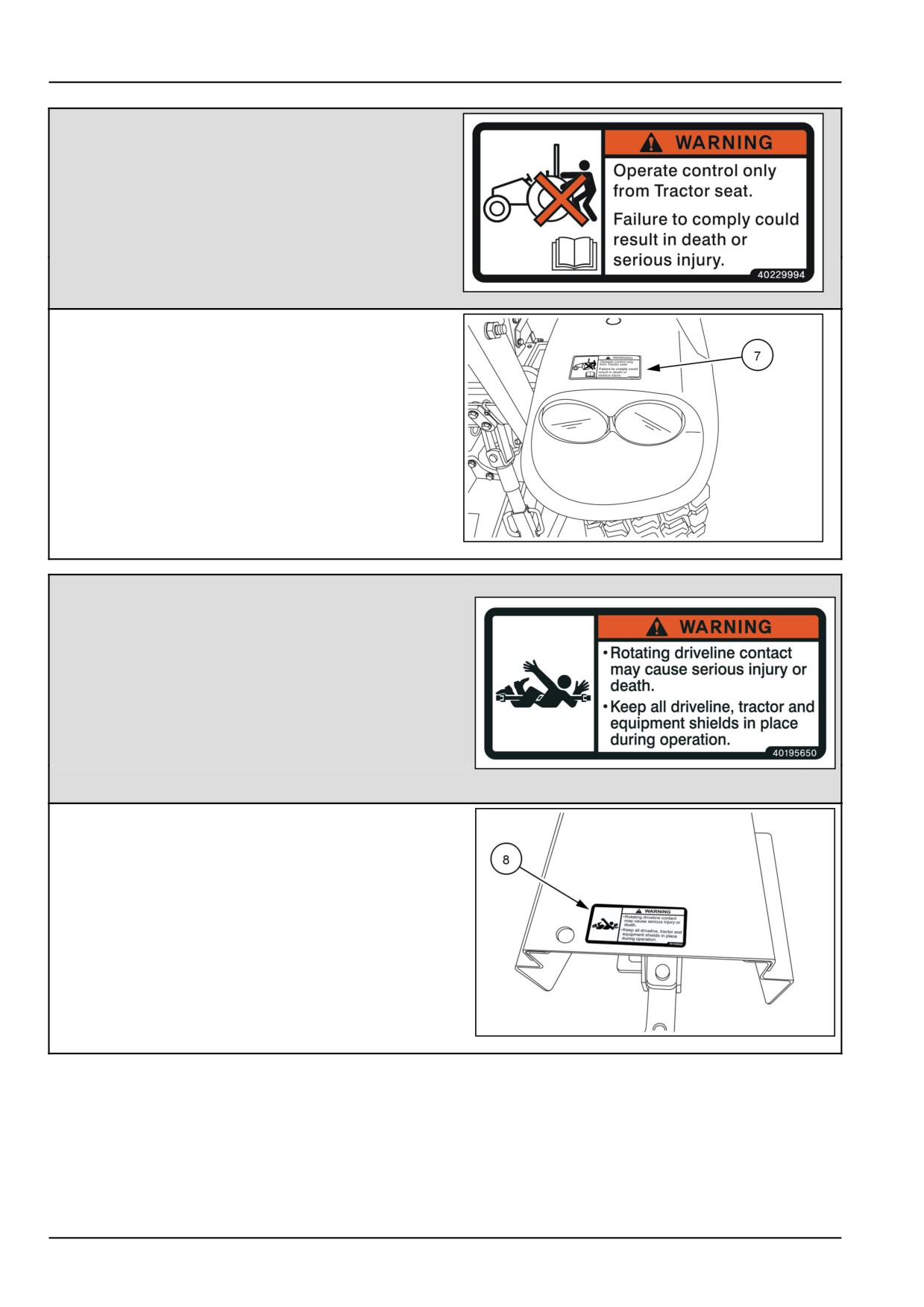
(7)
WARNING
Operate control only from tractor seat.
Failure to comply could result in death or serious
injury.
•
Quantity: 2
English Part Number: MT40229994
40229994
14
(7) Location: On the rear of the left-hand and right-hand
fenders.
NHIL13CT01209AA
15
(8)
WARNING
•
Rotating driveline contact may cause serious injury or
death.
•
Keep all driveline, tractor and equipment shields in
place during operation.
Quantity: 1
40195650
16
English Part Number: MT40195650
(8) Location: On top of the rear PTO Guard
NHIL13CT01010AA
17
2-20
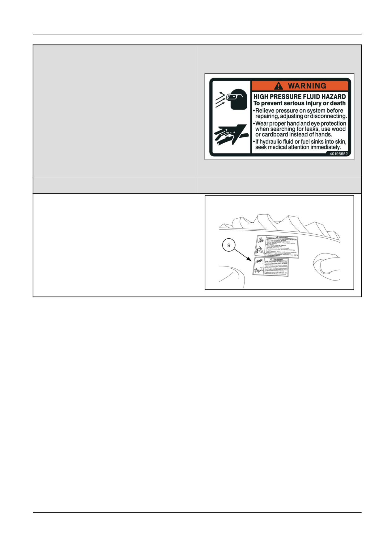
2 - SAFETY INFORMATION
(9)
WARNING
HIGH PRESSURE FLUID HAZARD
To prevent serious injury or death
•
Relieve pressure on system before repairing, ad-
justing or disconnecting.
•
Wear proper hand and eye protection when search-
ing for leaks, use wood or cardboard instead of
hands.
•
40195652
18
If hydraulic fluid or fuel sinks into skin, seek medi-
cal attention immediately.
Quantity: 1
English Part Number: MT40195652
(9) Location: On top of the left-hand fender.
83115222
19
2-21
//////////////////////////////////////////